

Page 1
Operator’s Manual
EWNT7 and EWNT10
End Wheel No Till Drill
Model Serial No.
EWNT7 1237Q to 1522Q
EWNT10 2333U to 4141U
Manufacturing, Inc.
P.O. Box 5060 l Salina, Kansas 67402-5060
Read the operator’s manual entirely. When you see this symbol, the subsequent in-
!
structions and warnings are serious - follow without exception. Your life and the lives of
others depend on it!
© Copyright 1997 Printed
4/17/2001
16685
Cover illustration may show optional equipment not supplied with standard unit.
150-082M
Page 2

General Information
Important Notice
Great Plains Manufacturing, Inc. provides this publication “as is” without warranty of any kind, either expressed or implied. While every precaution has been
taken in the preparation of this manual, Great Plains
Manufacturing, Inc. assumes no responsibility for errors or
omissions. Neither is any liability assumed for damages
resulting from the use of the information contained herein. Great Plains Manufacturing, Inc. reserves the right to
revise and improve its products as it sees fit. This publi-
This Operator’s Manual applies to the
7’ & 10’ End Wheel No-Till
Owner’s Information
Name: _____________________________________
cation describes the state of this product at the time of its
publication, and may not reflect the product in the future.
Printed in the United States of America.
For your convenience, record your Serial Number, Model Number and the Date Purchased in the spaces provided below. Have this information available when
calling your Great Plains Authorized Dealer.
Serial Number ________________
Address ____________________________________
City________________State ____ Zip ___________
Phone_______________________
Name of Dealership ___________________________
Dealer’s Name _______________________________
Address ____________________________________
City________________State ____ Zip ___________
Phone_______________________
Model Number ________________
Date Purchased _______________
EWNT7 and EWNT10 End Wheel No Till Drill 150-082M 4/25/06Great Plains Mfg., Inc.
Page 3

Table of Contents
Using This Manual . . . . . . . . . . . . . . . . . . . . . . . . . . 2
Introduction. . . . . . . . . . . . . . . . . . . . . . . . . . . . . . . . 2
Section 1 Safety Rules . . . . . . . . . . . . . . . . . . . . . . . 3
General Operation & Repair. . . . . . . . . . . . . . . . . 3
Transporting . . . . . . . . . . . . . . . . . . . . . . . . . . . . . 3
Tire Handling & Repair . . . . . . . . . . . . . . . . . . . . . 3
Safety Decals . . . . . . . . . . . . . . . . . . . . . . . . . . . . 3
Section 2 Assembly Instructions & Set-Up . . . . . . 6
Torque Values Chart. . . . . . . . . . . . . . . . . . . . . . . 6
Tire Inflation Chart . . . . . . . . . . . . . . . . . . . . . . . . 6
Pre-Assembly Checklist . . . . . . . . . . . . . . . . . . . . 7
Tractor Requirements . . . . . . . . . . . . . . . . . . . . . . 8
Tractor Drawbar Hook-Up. . . . . . . . . . . . . . . . . . . 8
Hook-Up For Ball Swivel Hitch . . . . . . . . . . . . . . . 8
Tractor Hydraulic Hook-Up . . . . . . . . . . . . . . . . . . 9
Bleeding The Hydraulic Lifting System. . . . . . . . . 9
Section 3 Basic Operation . . . . . . . . . . . . . . . . . . . 10
Operating The Lifting Hydraulics . . . . . . . . . . . . 10
Operating Transport Lock . . . . . . . . . . . . . . . . . . 10
Transporting . . . . . . . . . . . . . . . . . . . . . . . . . . . . 10
Section 4 Adjustments . . . . . . . . . . . . . . . . . . . . . . 11
Drive System Clutch. . . . . . . . . . . . . . . . . . . . . . 11
Drive Train Operation . . . . . . . . . . . . . . . . . . . . . 11
Clutch Shaft & Miter Gear Adjustment . . . . . . . . 12
Seed Rate Adjustments . . . . . . . . . . . . . . . . . . . 12
Fertilizer Drive . . . . . . . . . . . . . . . . . . . . . . . . . . 19
Fertilizer Rate . . . . . . . . . . . . . . . . . . . . . . . . . . . 19
7’ & 10’ Fertilizer Application Chart . . . . . . . . . . 19
Native Grass Drive . . . . . . . . . . . . . . . . . . . . . . . 20
Native Grass Rate . . . . . . . . . . . . . . . . . . . . . . . 20
Native Grass Seeding Adjustments . . . . . . . . . . 20
Sprocket Selection Chart . . . . . . . . . . . . . . . . . . 21
Coulter Adjustments . . . . . . . . . . . . . . . . . . . . . . 22
Coulter Hydraulic Depth Control. . . . . . . . . . . . . 22
Down Pressure Requirements . . . . . . . . . . . . . . 22
Individual Opener & Coulter . . . . . . . . . . . . . . . . 23
Disk Opener Spring Pressure Setting . . . . . . . . 23
Individual Opener Height . . . . . . . . . . . . . . . . . . 23
Opener Press Wheel Depth . . . . . . . . . . . . . . . . 23
Press Wheel Angle. . . . . . . . . . . . . . . . . . . . . . . 24
Section 5 Field Operations. . . . . . . . . . . . . . . . . . . 25
Drill Preparations . . . . . . . . . . . . . . . . . . . . . . . . 25
Operating Checklist . . . . . . . . . . . . . . . . . . . . . . 25
Section 6 Maintenance & Lubrication . . . . . . . . . . 26
Maintenance. . . . . . . . . . . . . . . . . . . . . . . . . . . . 26
Fertilizer Unit . . . . . . . . . . . . . . . . . . . . . . . . . . . 26
Storage. . . . . . . . . . . . . . . . . . . . . . . . . . . . . . . . 26
Lubrication . . . . . . . . . . . . . . . . . . . . . . . . . . . . . 26
Section 7 Troubleshooting. . . . . . . . . . . . . . . . . . . 29
Section 8 Specifications & Warranty. . . . . . . . . . . 31
Warranty. . . . . . . . . . . . . . . . . . . . . . . . . . . . . . . 32
4/17/2001 Great Plains Mfg., Inc. EWNT7 and EWNT10 End Wheel No Till Drill 150-082M
-1
Page 4

Using this Manual
Using this Manual
For your safety and to help in developing a better understanding of your equipment we highly recommend that
you read the operator sections of this manual. Reading
these sections not only provides valuable training but
also familiarizes you with helpful information and its lo-
Introduction
This manual has been prepared to instruct you in the
safe and efficient operation of your End Wheel No-Till.
Read and follow all instructions and safety precautions
carefully.
The parts on your End Wheel No-Till have been specially designed and should only be replaced with genuine
Great Plains parts. Therefore, should your End Wheel
No-Till require replacement parts go to your Great
Plains Dealer.
The right hand and left hand as used throughout this
manual is determined by facing in the direction the machine will travel when in use unless otherwise stated.
Serial Number
The serial number plate is located on the front right side
of the frame. It is suggested that the serial number and
purchase date also be recorded for your convenience in
the space provided on the checklist page at the beginning of this manual.
The serial number provides important information about
your drill and may be required to obtain the correct replacement part. Always use the serial number and model number when sending correspondence or when
ordering parts from your Great Plains. Dealer.
cation. The parts sections are for reference only and
don’t require cover to cover reading. After reviewing your
manual store it in a dry, easily accessible location for future reference.
symbol, be alert and carefully read the message that follows it. In addition to design and configuration of equipment; hazard control and accident prevention are
dependent upon the awareness, concern, prudence and
proper training of personnel involved in the operation,
transport, maintenance and storage of equipment.
Watch for the following safety notations through-out your
Operators Manual:
!
Indicates an imminently hazardous situation which, if not
avoided, will result in death or serious injury. This signal
word is limited to the most extreme situations.
Indicates a potentially hazardous situation which, if not
avoided, could result in death or serious injury.
Indicates a potentially hazardous situation which, if not
avoided, may result in minor or moderate injury. It may
also be used to alert against unsafe practices.
DANGER!
!
WARNING!
!
CAUTION!
!
The SAFETY ALERT SYMBOL indicates that there is a
potential hazard to personal safety involved and extra
safety precautions must be taken. When you see this
2
EWNT7 and EWNT10 End Wheel No Till Drill 150-082M 4/17/2001
NOTE: Indicates a special point of information which
requires your attention.
Great Plains Mfg., Inc.
Page 5

Section 1 Safety Rules
Section 1 Safety Rules
Most accidents are the result of negligence and carelessness, usually caused by failure of the operator to follow simple but necessary safety precautions. The
following safety precautions are suggested to help prevent such accidents. The safe operation of any machinery is a big concern to consumers and
manufacturers.Your End Wheel No-Till has been designed with many built-in safety features. However, no
one should operate this product before carefully reading
this Operators Manual.
!
General Operation & Repair
1. Never allow the drill to be operated by anyone who is unfamiliar with the operation of all functions of the unit. All
operators should read and thoroughly understand the instructions given in this manual prior to moving the unit.
2. Make sure safety rules are understood before operating
machinery or tractor.
3. Never permit any persons other than the operator to ride
on the tractor.
4. Never permit any persons to ride on or stand near the
drill while it is in operation.
5. Regulate your speed to the field conditions, maintaining
complete control at all times.
6. After repairing or adjusting, make sure all tools and
parts are removed from the implement before attempting
to operate it.
7. Do not grease or oil machine while it is in operation.
8. Loose fitting clothing should not be worn as it may catch
in moving parts.
9. Never dismount from a moving tractor.
10. Do not leave the tractor or the implement unattended
with the engine running.
11. Do not stand between the tractor and the implement during hitching.
12. Detach and store implements in an area where children
normally do not play. Stabilize implements by using suitable supports and block wheels.
13. If a hydraulic leak develops, correct it immediately. Escaping hydraulic oil can have extremely high pressure. A
stream of high pressure oil may easily penetrate the skin
as with modern needle-less vaccination equipment - but
with the exception that hydraulic fluid may cause blood
poisoning. It is imperative that the connections are tight
and that all lines and pipes are in good condition. If an
injury is caused by the escaping hydraulic fluid, see doctor at once!
14. Use a piece of cardboard or wood to detect leaks of hydraulic oil under pressure.
15. Be sure to relieve all hydraulic pressure before disconnection any lines or pipes between the implement and the tractor hydraulic system. Keep all guards and shields in place.
Transporting
1. Use good judgement when transporting tractor and implements on the highway. Always maintain complete control of the machine.
2. Limit transport speed to 20 mph. Transport only with a
farm tractor of sufficient size and horse power. See
“Tractor Requirements” Section 2,page 8.
3. Always make sure flashing safety lights, “Slow Moving
Vehicle” emblem, and reflectors are in place and visible
prior to transporting the machine on public roads.
4. Know your state and local laws concerning highway
safety and regulations. Comply with these laws when
transporting machinery.
5. Use warning flags or approved warning lights at night
and during other periods of poor visibility. Do your best
to prevent highway accidents.
Tire Handling & Repair
1. Tire changing can be dangerous and should be preformed by trained personnel using the correct tools and
equipment.
2. Do not re-inflate a tire that has been run flat or seriously
under inflated. Have it checked by qualified personnel.
3. When removing and installing wheels, use wheel handling equipment adequate for the weight involved.
Safety Decals
1. Your End Wheel No-Till comes equipped with all safety
decals in place. They were designed to help you safely
operate your drill. Read and follow their directions.
2. Keep safety decals clean and legible.
3. Replace all damaged or missing safety decals. To order
new safety decals go to your Great Plains Dealer and refer to the parts section for safety decal package part number.
4. Replace these decals whenever they become worn or unreadable. To instal new safety decals:
a. Clean the area the decal is to be placed
b. Peel backing from the decal. Press firmly on to sur-
face being careful not to cause air bubbles under the
decal.
4/17/2001 Great Plains Mfg., Inc.
EWNT7 and EWNT10 End Wheel No Till Drill 150-082M
-3
Page 6

Section 1 Safety Rules
13846
818-188C
Transport Speed Warning
818-229C
Amber Reflectors
13846
13847
818-188C
Transport Speed Warning
818-230C
Red Reflector
13849
4
EWNT7 and EWNT10 End Wheel No Till Drill 150-082M 4/17/2001
Great Plains Mfg., Inc.
Page 7

Section 1 Safety Rules
13848
818-003C
Slow Moving Vehicle Emblem
4/17/2001 Great Plains Mfg., Inc.
EWNT7 and EWNT10 End Wheel No Till Drill 150-082M
-5
Page 8

Section 2 Assembly Instructions & Set-Up
Section 2 Assembly Instructions & Set-Up
Torque Values Chart for Common Bolt Sizes
Bolt Head Identification
Bolt Head Identification
Bolt Size
(Inches)
1
in-tpi
1/4" - 20 7.4 5.6 11 8 16 12 M 5 X 0.8 436597
1/4" - 28 8.5 6 13 10 18 14 M 6 X 1 7 5 11 8 15 11
5/16 - 18 15 11 24 17 33 25 M 8 X 1.25 17 12 26 19 36 27
5/16" - 24 17 13 26 19 37 27 M 8 X 1 18 13 28 21 39 29
3/8" - 16 27 20 42 31 59 44 M10 X 1.5 33 24 52 39 72 53
3/8" - 24 31 22 47 35 67 49 M10 X 0.75 39 29 61 45 85 62
7/16" - 14 43 32 67 49 95 70 M12 X 1.75 58 42 91 67 125 93
7/16" - 20 49 36 75 55 105 78 M12 X 1.5 60 44 95 70 130 97
1/2" - 13 66 49 105 76 145 105 M12 X 1 90 66 105 77 145 105
1/2" - 20 75 55 115 85 165 120 M14 X 2 92 68 145 105 200 150
9/16" - 12 95 70 150 110 210 155 M14 X 1.5 99 73 155 115 215 160
9/16" - 18 105 79 165 120 235 170 M16 X 2 145 105 225 165 315 230
5/8" - 11 130 97 205 150 285 210 M16 X 1.5 155 115 240 180 335 245
5/8" - 18 150 110 230 170 325 240 M18 X 2.5 195 145 310 230 405 300
3/4" - 10 235 170 360 265 510 375 M18 X 1.5 220 165 350 260 485 355
3/4" - 16 260 190 405 295 570 420 M20 X 2.5 280 205 440 325 610 450
7/8" - 9 225 165 585 430 820 605 M20 X 1.5 310 230 650 480 900 665
7/8" - 14 250 185 640 475 905 670 M24 X 3 480 355 760 560 1050 780
1" - 8 340 250 875 645 1230 910 M24 X 2 525 390 830 610 1150 845
1" - 12 370 275 955 705 1350 995 M30 X 3.5 960 705 1510 1120 2100 1550
1-1/8" - 7 480 355 1080 795 1750 1290 M30 X 2 1060 785 1680 1240 2320 1710
1 1/8" - 12 540 395 1210 890 1960 1440 M36 X 3.5 1730 1270 2650 1950 3660 2700
1 1/4" - 7 680 500 1520 1120 2460 1820 M36 X 2 1880 1380 2960 2190 4100 3220
1 1/4" - 12 750 555 1680 1240 2730 2010
1 3/8" - 6 890 655 1990 1470 3230 2380
1 3/8" - 12 1010 745 2270 1670 3680 2710
1 1/2" - 6 1180 870 2640 1950 4290 3160
1 1/2" - 12 1330 980 2970 2190 4820 3560
Grade 2 Grade 5
N · m2ft-lb3N · m ft-lb N · m ft-lb mm x pitch4N · m ft-lb N · m ft-lb N · m ft-lb
Grade 8
Bolt Size
(Metric)
1
in-tpi = nominal thread dia .in inches-threads per inch
2
N· m = newton-meters
3
ft-lb= foot pounds
4
mm x pitch = nominal thread dia. in millimeters x thread pitch
5.8 8.8 10.9
Class 5.8 Class 8.8 Class 10.9
Tire Inflation Chart
Tire Size Inflation PSI
7.50 x 20" 4-Ply Drill Rib 28
9.0 x 22.5 10-Ply Highway Service 70 70
9.0 x 24" 8-Ply Rib Implement 40
9.5L x 15" 6-Ply Rib Implement 32
9.5L x 15" 8-Ply Rib Implement 44
9.5L x 15" 12-Ply Rib Implement 60
6
EWNT7 and EWNT10 End Wheel No Till Drill 150-082M 4/17/2001
Tire Size Inflation PSI
11L x 15" 6-Ply Rib Implement 28
11L x 15" 12-Ply Rib Implement 52
12.5L x 15" 8-Ply Rib Implement 36
12.5L x 15" 10-Ply Rib Implement 44
16.5L x 16.1" 10-Ply Rib Implement 36
41 x 15" x 18 - 22-Ply Rib Implement 44
Great Plains Mfg., Inc.
Page 9
Section 2 Assembly Instructions & Set-Up
Pre-Assembly Checklist
Check
All major components
Fasteners that were shipped with the End Wheel No-Till Drill.
NOTE: Some of the hardware from the factory has been installed in the location where it will be used.
Have a minimum of 2 people at hand while assembling the End Wheel No-Till Drill.
Have a fork lift or loader along with chains and safety stands ready for the assembly task.
If you are unsure where a fastener is used, use the parts section of this manual to identify it. Be sure the part gets
used in the correct location.
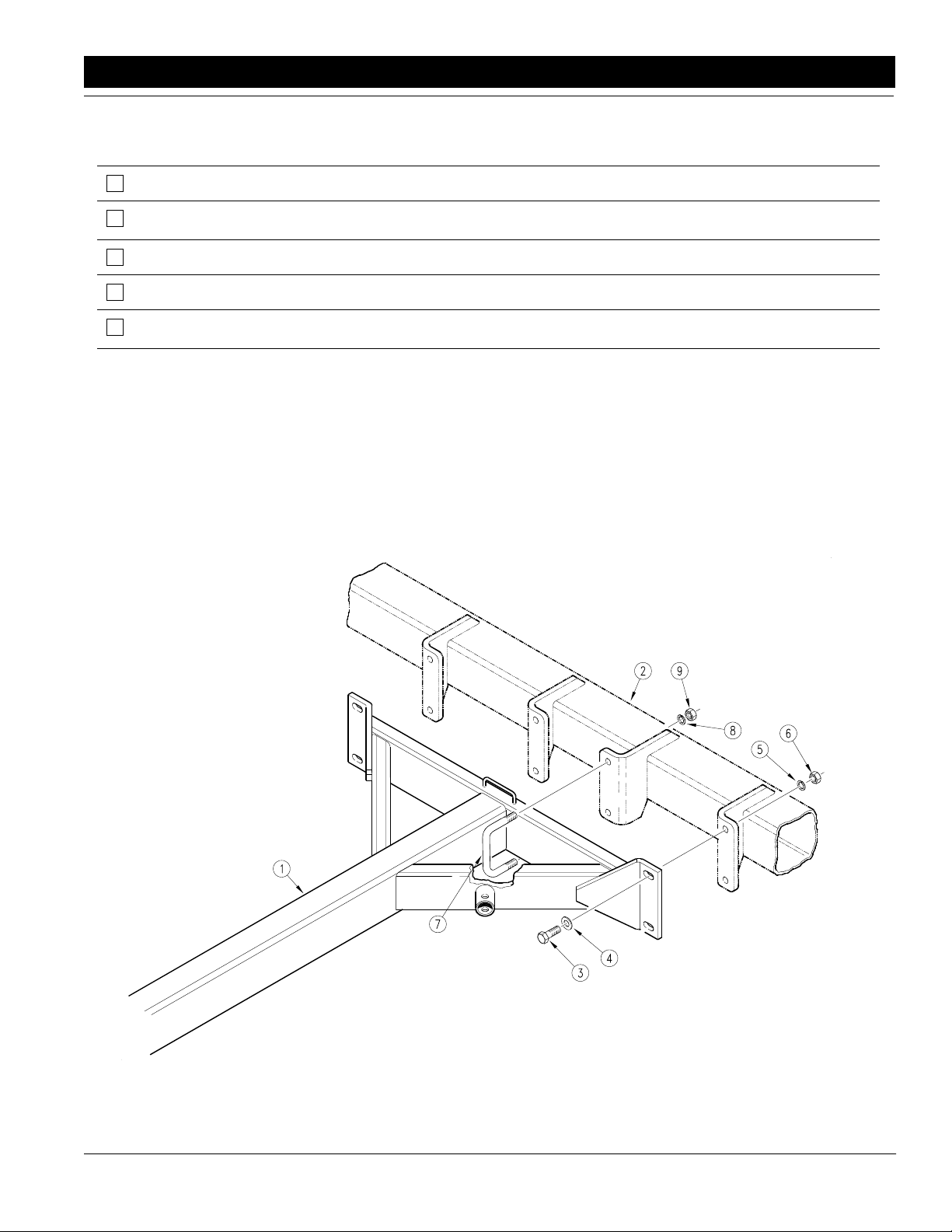
Refer to Figure 2-1:
Before starting the drill assembly, be sure that the drill
frame is safely supported and the end wheel tires are
blocked.
Bolt the outside legs of the tongue weldment (#1) to the
drill frame (#2) using 3/4" x 2 1/4" long bolts (#3), 3/4"
SAE flat washers (#4), 3/4" lock washers (#5), and 3/4"
hex nuts (#6).
Connect the rear tube of the tongue (#1) to the drill
frame (#2) using 3/4" x 6 1/32" x 3 1/4" long u-bolts (#7),
3/4" lock washers (#8), and 3/4" hex nuts (#9).
Tighten all hardware to the torque specification listed in
the "Nut & Bolt Torquing Chart" on page 6.
4/17/2001 Great Plains Mfg., Inc.
Tongue & Pull Bar Assembly
Figure 2-1
EWNT7 and EWNT10 End Wheel No Till Drill 150-082M
10681
-7
Page 10
Section 2 Assembly Instructions & Set-Up
Tractor Requirements
To operate your Great Plains End Wheel No-Till Drill in
most field conditions, a tractor of adequate size should
be used. For 7’ drills, a 55 horsepower tractor is required. For 10’ drills, a 75 horsepower tractor is required.
7’ and 10’ drills require 1-set of remote outlets.
Tractor Drawbar Hook-Up
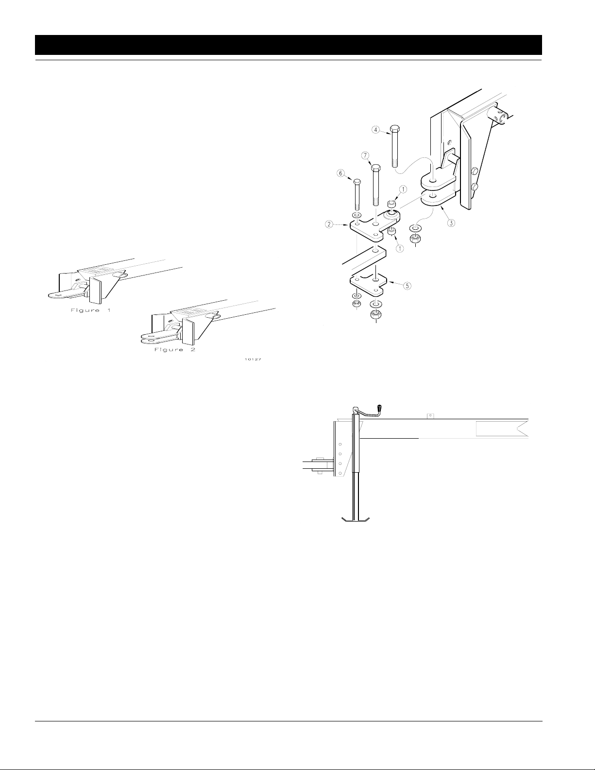
Refer to Figure 2-2 & Figure 2-3:
The Great Plains No-Till Drill is equipped with either a
single strap, Figure 2-2, clevis style hitch, Figure 2-3, or
a ball swivel hitch, Figure 2-5. For proper field operation,
the tongue of the drill should run level, parallel to the
ground in field position.
11549
10127
Single Strap Hitch
Figure 2-2
Clevis Style Hitch
Figure 2-3
Tractor Drawbar
Hook-Up For Ball Swivel Hitch
Refer to Figure 2-4:
Place a spacer tube (#9) above and below the ball swivel. Bolt the ball swivel {top hitch weldment} (#1) and
spacer tubes (#9) to the drill clevis hitch with a 1" x 5"
long bolt (#10), 1" USS flat washer (#11), and 1" nylock
nut (#12).
Back the tractor to the drill hitch. Using the screw jack,
adjust the drill tongue up or down to center the drawbar
below the upper hitch plate (#1). Place hitch weldment
(#1) on top of the tractor drawbar, aligning the rear hole
in the hitch weldment with the large hole in the drawbar.
Place the lower hitch plate (#2) under the drawbar and
attach to the hitch weldment (#1) with {2} 5/8" x 4" long
bolts (#3), 5/8" flat washers (#4), 5/8" nylock nuts (#5).
Bolt the top hitch weldment (#1) through the hole in the
drawbar to the lower hitch plate (#2) with a 1" x 5 1/2"
long bolt (#6), 1" USS flat washer (#7), and 1" nylock nut
(#8).
Ball Swivel Hitch
Figure 2-4
Refer to Figure 2-5:
1. With the drill lowers and in the field position, adjust
the tongue jack to level the tongue.
Jack In Vertical Position
Figure 2-5
2. Back the tractor draw bar up to the drill hitch to determine the amount of adjustment required.
Refer to Figure 2-6:
3. The mounting holes in the hitch have been offset so
the hitch can be turned over and bolted on in three
different hitch positions, giving you six different hitch
heights.
10150
8
EWNT7 and EWNT10 End Wheel No Till Drill 150-082M 4/17/2001
Great Plains Mfg., Inc.
Page 11

Section 2 Assembly Instructions & Set-Up
Bleeding the
Hydraulic Lifting System
The implement lifting system is equipped with rephasing
type hydraulic cylinders that require a special procedure
for bleeding air from the hydraulic circuits. Read and follow the procedure carefully. The rephasing type cylinders will not function properly with air in the hydraulic
circuit. Bleeding the system may have been done during
initial set up of the drill.
10123
Hitch Height Adjustment
Figure 2-6
4. Connect the hitch to the tractor using a pin of adequate strength (minimum 1" diameter).
Refer to Figure 2-7:
5. Unpin the tongue jack, and pin it on top of the
tongue.
Jack In Transport Position
Figure 2-7
NOTE: Make sure the hitch is securely bolted to the
drill tongue.
Your drill comes equipped with a hitch safety chain. The
safety chain should be securely attached to the drill hitch
and the tractor drawbar whenever towing or planting.
11833
Tractor Hydraulic Hook-Up
Route the lift hydraulic hoses along the tongue and
through the hose loop on the front of the tongue. Connect the hoses to the tractor remote outlets.
NOTE: Check the hydraulic fluid in the tractor resevoir and fill to the proper level. Add fluid to the system as needed. A low resevoir level may draw air
back into the system, causing jerky or uneven cylinder movements. The drill system capacity is approximately 1 gallon.
1. Jack up and support the front member of the drill at
a point close to each end wheel. If the end wheel
cylinders have previously been engaged, they may
be used to assist in raising the frame.
2. With the frame blocked and supported, unpin the
cylinders from the drill frame and turn the cylinders
upside down and wire or otherwise safely support
the rod end port higher than the base end port.
3. With the tractor engine at an idle speed, hold the remote lever on to put fluid into the lifting circuit. When
the cylinders have completely extended, hold the remote lever on for one minute.
4. Retract the cylinders. Extend the cylinders again
and hold the remote lever on for one more minute.
Repeat this step two more times to completely bleed
the system.
5. Repin the cylinders to the drill frame, rod end to the
wheel arm. If air is trapped in either cylinder, the affected cylinder will have a spongy, erratic movement
and the drill will not raise evenly. Refill the tractor hydraulic fluid reservoir to its proper level.
NOTE: After the drill is raised, a slight settling will occur due to the action of the rephasing cylinders.
!
Escaping fluid under pressure can have sufficient force to penerate the skin. Check all hydraulic lines and hoses before applying pressure. Fluid escaping from a very small hole can be
almost invisible. Use paper or cardboard, not body parts, to
check for suspected leaks. If injured, seek medical assistance
from a doctor that is familiar with this of injury. Foreign fluids
in the tissue must be surgically removed within a few hours or
gangrene will result.
4/17/2001 Great Plains Mfg., Inc.
CAUTION!
IMPORTANT: When using sealant on pipe threads the
friction between the threads is reduced; therefore, be
certain not to over tighten causing damage to the cylinder port or fitting.
EWNT7 and EWNT10 End Wheel No Till Drill 150-082M
-9
Page 12

Section 3 Basic Operation
Section 3 Basic Operation
Operating the
Lifting Hydraulic System
The lift cylinders may after a period of time get out of
time or phase. The effects of this can be seen when one
side of the drill is running too low or too high because its
lift cylinder is either overextended or overretracted compared to the other lift cylinder. To rephase the cylinders,
raise the drill completely up and hold the tractor hydraulic lever on for a few seconds to give the cylinders time to
rephase. This should be done each time the drill is
raised out of the ground. Momentarily reversing the hydraulic lever immediately after rephasing to allow the cylinders to retract about 1/2" will help in maintaining a level
drill.
Transporting
Operating Transport Lock
Refer to Figure 3-1:
When transporting your drill, you should always lock
your drill in the raised position. Fully extend the lift cylinders to raise the drill for transporting. Remove the lock
pins from the storage position, Figure 3-1. {One on each
side of the drill frame.}
Lock Out Hubs
Before transporting the drill, you should always check
the following items:
1. Make sure that drill is securely attached to the draw
bar of the tractor and that the hitch safety chain has
been securely attached.
2. Check to see that the transport tires have the proper
inflation as noted on page 6.
Refer to Figure 3-3:
3. Make sure the drive lockout hub (left side) is disengaged before transporting, see Figure 3-3. This will
protect from excessive wear on the gauge wheel
drive system.
4. This drill comes equipped with a transport lock pin
located on each side of the drill frame. Make sure
the pin is in its transport position as shown in
Figure 3-2.
5. Comply with all Federal, State and Local Safety
Laws when traveling on public roads.
6. Remember, the drill is wider than the tractor and extreme care must be taken to allow for safe clearance.
10151
11890
10252
Lock Pin In Field - Storage Position
Figure 3-1
Refer to Figure 3-2:
Place the lock pin through the frame channel as shown
in Figure 3-2. Before lowering the drill, you must first extend the lift cylinders completely and move the lock pins
to their storage position.
11838
Lock Pin In Transport Position
Figure 3-2
10
EWNT7 and EWNT10 End Wheel No Till Drill 150-082M 4/17/2001
!
This Drill should never be pulled faster than 20 miles per
hour.
CAUTION!
Drive Lock Out Hub
Figure 3-3
Great Plains Mfg., Inc.
Page 13
Section 4 Adjustments
Section 4 Adjustments
Drive System Clutch
Refer to Figure 4-1:
The main drive clutch (#1) on your drill is a mechanical
release - jaw style design which may require some adjustments before using your drill. Raise the drill to the
transport position. Check between the two cam plates
(#2) which disengage the jaws (#3) & (#4) of the clutch
halves. The clutch jaws (#3) & (#4) should be completely separated at this point.
Adjustments can be made to the cam plate (#6) by loosening the bolts, and nuts (#5) in the clutch tab(#7).
Whenever adjusting the clutch, check to be sure the
clutch jaws (#3) & (#4) are engaged completely when
the drill is lowered to the field position. The clutch jaws
(#3) & (#4) should also be completely disengaged when
the drill is raised for transport.
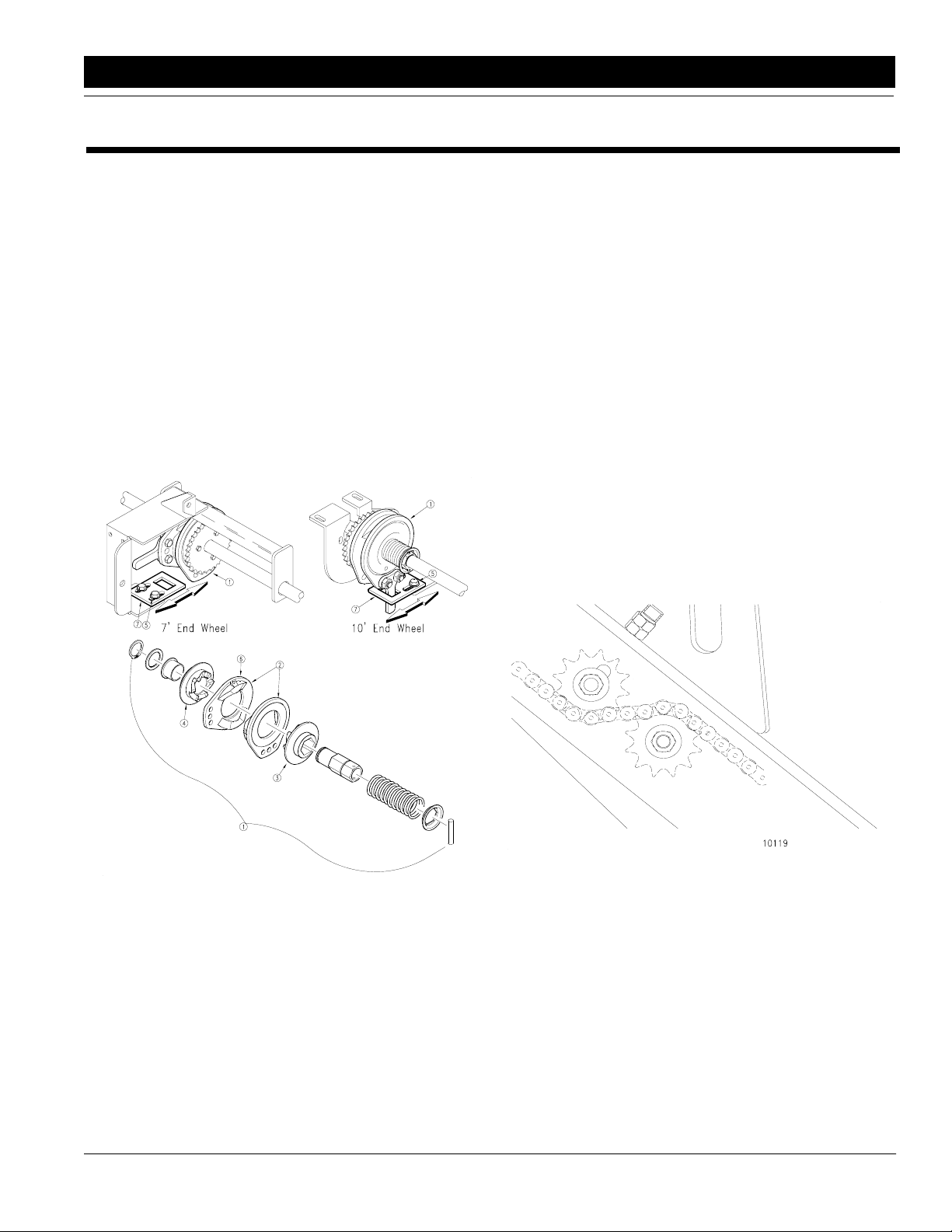
Drive Train Operation
Refer to Figure 4-2:
Your grain drill uses standard no. 40 roller chain through
out its drive system. The drive system is simple and designed for low maintenance. All chain idlers should be
checked at the beginning of each season to insure that
they are adjusted properly.
To do a maintenance inspection, simply check each idler
to insure that it is taking up any excess chain slack. On
fertilizer and native grass drills the inspection cover for
the drive is located on the outside of the left box end panel and this cover must be removed to inspect the fertilizer
and native grass drive chain and idler.
In the left wheel arm are two idler sprockets, Figure 4-2,
which should be readjusted after the first 100 acres of
drill use and then at the beginning of each season. To
adjust, move the front idler sprocket, on the top of the
chain, down, by loosening the jam nut and screwing the
adjustment stud in. Chain idlers should always be kept
snug against the slack side of the chain. Do not over
tighten chains, it will cause excessive wear on idlers and
drive components. Retighten the jam nut to maintain the
idler position.
14018
Jaw Clutch Adjustment
Figure 4-1
4/17/2001 Great Plains Mfg., Inc.
10119
Idler Sprocket Adjustments
Figure 4-2
EWNT7 and EWNT10 End Wheel No Till Drill 150-082M
-11
Page 14
Section 4 Adjustments
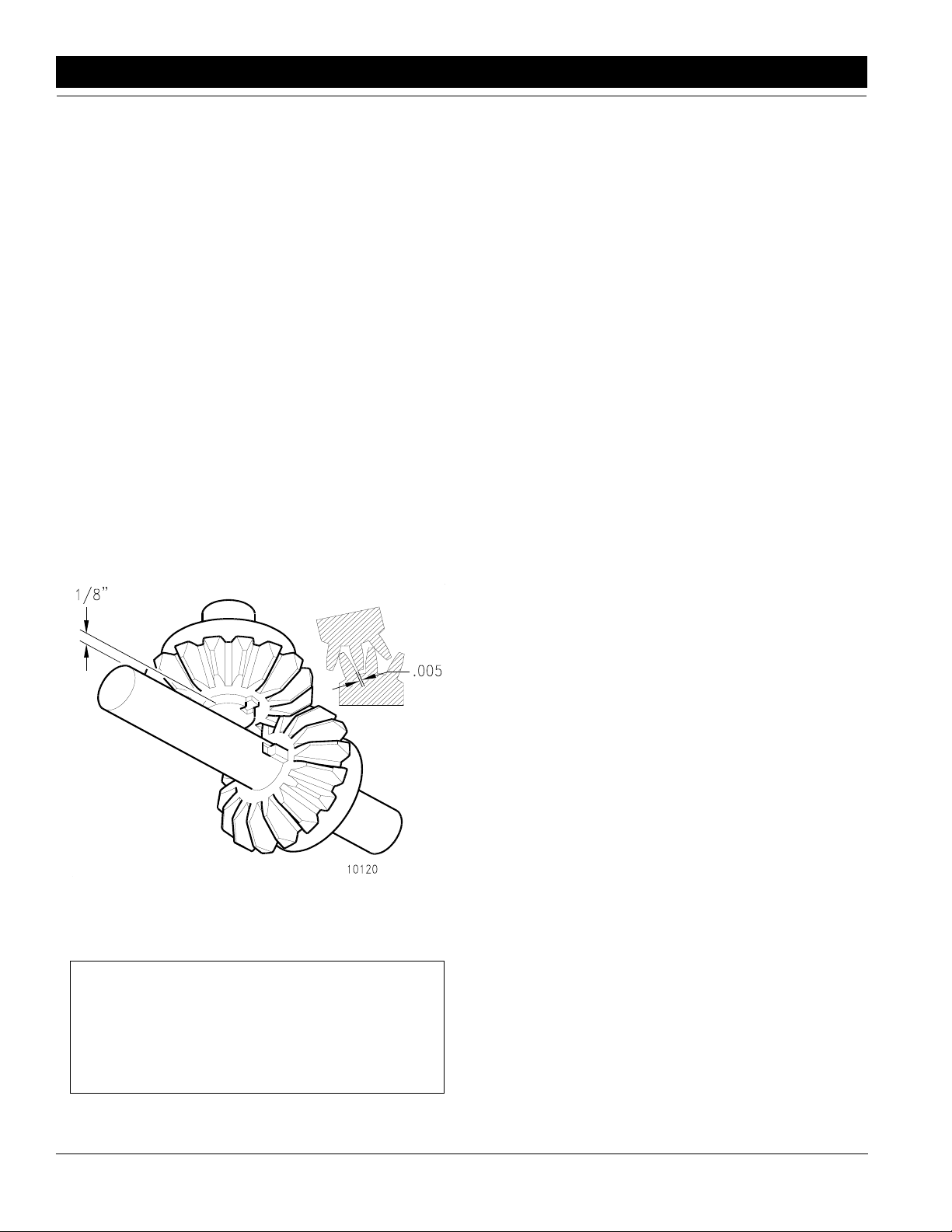
Clutch Shaft & Miter Gear Alignment
Refer to Figure 4-3:
The speed change box is designed to give you a variety
of speeds for different types of seeds and rates. It is a
linear shift pattern design with constant mesh gearing
and totally sealed to keep the dirt out. There should be
no lubrication required unless service is needed. The input shaft is located on the bottom of the box and is driven
with mitered gears. It is recommended that lubrication
not be applied to the gears. If the gears are lubricated
the lubrication will attract dirt and increased wear will result. It is very important that the mitered gears back lash
is set correctly. Using a (.005) wire type feeler gauge or
a piece of wire measuring (.005) in diameter, insert it between the teeth of the two gears where they mesh, Figure 4-3. The adjustment is done by loosening the set
screws in the bearing on the jack shaft nearest the gear.
Loosen the bearing bracket mounting bolts under the
gearbox. Then slide bearing bracket, bearing and gear
over to gear on the gear box input shaft with wire gauge
inserted between the teeth and tighten the bearing set
screws, then tighten the bearing bracket mounting bolts.
After adjustments are made, rotate the jackshaft to see
that no binding occurs within the gears.
10120
Speed Change Miter Gears
Figure 4-3
Seed Rate Adjustments
NOTE: Seeding rates will vary greatly with variations
in sizes of the seeds. Although the seeding rates listed in this manual are based on an average seed
size, we recommend that you test and adjust your
drill using the procedures listed below to help insure
an accurate seeding rate.
Refer to Figure 4-4:
1. To adjust your seeding rate, first you must decide
which drive type you need (see "Seed Rate Charts"
on the following pages). In order to change drive
types, move the lever on the speed change box to
desired setting, Figure 4-4.
2. There are many factors which will affect seeding
rates: seed treatment, weight of seed, size of seed,
surface condition of seed, and tire configuration,
pressure and slippage. Minor adjustments will probably be needed to compensate for the above factors.
3. The pounds-per-acre in the seed charts are based
on drills having 9.00 x 24 rib implement tires with
proper inflation as listed on page 6.
4. The large differences in seed sizeand treatment can
cause a wide variation in actual seeding rates. The
seed rate charts on the following pages are based
on average size seed. This may differ from the seed
you are using. Use the seed rate charts as a guide.
Set the pounds-per-acre desired at the indicator
number for your row spacing and complete the following procedure to calibrate the drill for your specific seed.
a. Lower the drill hydraulically to planting position
in order to activate the clutch.
b. Raise the drive (left) end tire off the ground us-
ing a jack.
c. Rotate the tire to see that the drive system is
working properly and that the feed cups are free
from foreign matter.
d. Place several pounds of seed over three of the
feeder cups at the outboardend of the seed box.
Make sure all feed cup handles are set in the
same position on all the feeder cups.
e. Set the feed cup adjustment lever to the desired
setting.
f. Pull the seed tubes out of these openers.
g. Place a container under the three seed tubes to
gather the seed as it is metered.
h. Rotate the drive gauge wheel until one acre has
been tallied on the acremeter. This will be approximately 422 rotations on a 10’ drill and 592
rotations on a 7’ drill. Be sure to check the three
feeder cups to makesure each cup has plentyof
seed coming into it.
i. Weigh the seed which has been metered. Di-
vide by three. This will give you the ounces/
pounds metered by each feeder cup. Multiply by
the number of openers on your drill to arrive at
the total pounds-per-acre you would meter at
that setting. If this figure is different than desired, set your feed cup adjustment lever accordingly.
12
EWNT7 and EWNT10 End Wheel No Till Drill 150-082M 4/17/2001
Great Plains Mfg., Inc.
Page 15

Section 4 Adjustments
Seed Rate Adjustment
Figure 4-4
5. You may want to repeat the calibration procedure if
the results of you calibration vary greatly from the
suggested settings contained in this manual.
10152
6. Seed cup plugs are available for your drill, which will
enable you to block off specific rows from metering
seed. Order Great Plains Part #109-009H.
NOTE: This will change the amount of seed metered
from the charts.
IMPORTANT: Tire size and field conditions will also affect seeding rates. Be certain that your drill rib tires are
9.00 x 24 and that they have proper inflation. When drill-
ing, check the amount of seed you are using by noting
acres drilled, amount of seed added to drill, and level of
seed in drill box. If you suspect that you are drilling more
or less than desired, and you have accurately calibrated
the drill to your seed, you may need to adjust the seeding rate slightly to compensate for your field conditions.
4/17/2001 Great Plains Mfg., Inc.
EWNT7 and EWNT10 End Wheel No Till Drill 150-082M
-13
Page 16

Section 4 Adjustments
Seed Rate Charts
HARD RED WINTER WHEAT SEED RATE INDICATOR SETTING NUMBER
DRIVE TYPE 1 0 5 10 15 20 25 30 35 40 45 50 55 60 65 70 75 80 85 90 95 100
Row Spacing Pounds Per Acre
7" 0 11 19 27 35 44 52 62 71 81 91 101 110 122 133 145 153 161 166 174 180
7 1/2" 0 10 17 24 32 40 48 56 65 74 83 92 100 112 121 132 140 147 152 159 164
8" 0 9 16 23 30 39 46 54 62 70 79 88 96 100 112 121 132 140 145 152 156
10" 0 7 13 19 24 31 36 43 49 56 63 70 77 85 92 101 106 112 116 121 125
*Based On 60#/Bushel
HARD RED WINTER WHEAT SEED RATE INDICATOR SETTING NUMBER
DRIVE TYPE 2A 0 5 10 15 20 25 30 35 40 45 50 55 60 65 70 75 80 85 90 95 100
Row Spacing Pounds Per Acre
7" 0 7 13 18 23 30 35 41 47 54 61 67 73 81 88 97 102 107 111 116 120
7 1/2" 0 6 11 16 21 27 32 38 43 49 55 61 67 74 81 88 93 98 101 106 109
8" 0 6 10 15 20 26 30 36 41 47 53 58 64 71 77 84 89 93 96 101 104
10" 05 9121621242933374247515762677175778183
*Based On 60#/Bushel
RICE SHORT GRAIN SEED RATE INDICATOR SETTING NUMBER
DRIVE TYPE 1 0 5 10 15 20 25 30 35 40 45 50 55 60 65 70 75 80 85 90 95 100
Row Spacing Pounds Per Acre
7" 0 2 9 15 21 28 35 41 47 54 61 67 76 81 86 92 98 105 107 107 109
7 1/2' 0 2 8 14 19 26 32 38 45 51 57 64 71 76 82 86 93 98 101 101 103
8" 02 7131825303542475459667175818792959596
10" 01 6111520252934384347535761667074767677
RICE SHORT GRAIN SEED RATE INDICATOR SETTING NUMBER
DRIVE TYPE 1A 0 5 10 15 20 25 30 35 40 45 50 55 60 65 70 75 80 85 90 95 100
Row Spacing Pounds Per Acre
7" 0 5 15 28 40 50 66 79 93 107 123 136 157 169 180 194 210 223 228 231 232
7 1/2" 0 4 15 26 37 47 63 75 87 101 116 127 148 159 170 182 197 210 214 217 218
8" 0 4 14 25 35 45 58 70 82 95 108 119 139 149 159 171 186 197 201 204 205
10" 0 3 11 20 28 35 47 56 66 76 86 96 111 120 127 137 148 157 161 163 164
RICE LONG GRAIN SEED RATE INDICATOR SETTING NUMBER
DRIVE TYPE 1 0 5 10 15 20 25 30 35 40 45 50 55 60 65 70 75 80 85 90 95 100
Row Spacing Pounds Per Acre
7" 01 6131927343946525864697478838995959697
7 1/2" 0 1 5 12 17 25 31 36 44 49 55 60 65 70 74 78 84 89 89 90 92
8" 01 5111624293541465156616669737884848586
10" 0 0 4 9 14 19 24 27 33 37 41 46 49 53 56 58 63 67 67 68 69
RICE LONG GRAIN SEED RATE INDICATOR SETTING NUMBER
DRIVE TYPE 1A 0 5 10 15 20 25 30 35 40 45 50 55 60 65 70 75 80 85 90 95 100
Row Spacing Pounds Per Acre
7" 0 2 9 22 36 50 63 78 90 100 116 131 143 152 165 175 187 202 207 210 211
7 1/2" 0 2 8 21 34 46 59 74 85 94 110 123 135 143 156 165 176 190 196 197 198
8" 0 2 8 19 32 44 56 69 80 88 103 116 126 134 146 154 165 178 183 186 187
10" 0 1 6 15 25 35 45 56 64 71 83 93 101 107 116 124 132 143 147 148 149
BARLEY SEED RATE INDICATOR SETTING NUMBER
DRIVE TYPE 1 0 5 10 15 20 25 30 35 40 45 50 55 60 65 70 75 80 85 90 95 100
Row Spacing Pounds Per Acre
7" 00 813192530364248535965717682879398104109
7 1/2" 0 0 7 13 18 23 29 34 39 45 50 55 60 66 71 76 82 87 93 89 102
8" 00 7121722272837424752576267727782879397
10" 0 0 6 9 13 18 22 25 29 34 38 41 45 50 54 57 61 65 70 74 78
OATS SEED RATE INDICATOR SETTING NUMBER
DRIVE TYPE 1 0 5 10 15 20 25 30 35 40 45 50 55 60 65 70 75 80 85 90 95 100
Row Spacing Pounds Per Acre
7" 04 8131824303542485460677279869197101106110
7 1./2" 0 3 7 12 16 22 27 32 38 44 49 55 61 66 72 78 83 88 93 97 100
8" 03 7111521263036424753586369757984889296
10" 0 3 6 9 13 17 21 24 29 34 37 42 47 50 55 60 63 67 71 74 76
*Based On 39#/Bushel
14
EWNT7 and EWNT10 End Wheel No Till Drill 150-082M 4/17/2001
Great Plains Mfg., Inc.
Page 17

Section 4 Adjustments
RYE SEED RATE INDICATOR SETTING NUMBER
DRIVE TYPE 2 0 5 10 15 20 25 30 35 40 45 50 55 60 65 70 75 80 85 90 95 100
Row Spacing Pounds Per Acre
7" 0 0 3 6 9 12 15 17 22 23 25 29 32 35 37 41 45 48 49 52 53
7 1/2" 0 0 3 5 8 11 14 16 21 22 24 28 30 33 35 38 42 46 46 49 49
8" 0 0 3 5 8 10 13 15 19 20 23 26 29 31 33 36 39 43 44 46 47
10’ 00 2 4 6 810141617192123252729 3234353738
MILLET SEED RATE INDICATOR SETTING NUMBER
DRIVE TYPE 2 0 5 10 15 20 25 30 35 40 45 50 55 60 65 70 75 80 85 90 95 100
Row Spacing Pounds Per Acre
7" 0 1 4 6 9 12 14 16 19 22 25 28 32 35 39 42 46 51 53 53 54
7 1/2" 0 1 3 5 8 11 13 15 17 21 24 27 31 33 36 40 44 47 49 50 51
8" 0 1 3 5 8 10 12 14 16 19 22 25 28 30 34 38 41 45 46 47 48
10" 0 0 2 4 6 8 9 11 13 15 18 21 23 25 27 29 33 36 37 38 39
BUCKWHEAT SEED RATE INDICATOR SETTING NUMBER
DRIVE TYPE 1 0 5 10 15 20 25 30 35 40 45 50 55 60 65 70 75 80 85 90 95 100
Row Spacing Pounds Per Acre
7" 0 4 10 18 25 32 40 48 52 63 73 82 86 96 104 117 128 142 151 152 155
7 1/2" 0 3 9 17 23 30 37 46 49 60 68 77 81 90 98 111 121 134 142 146 146
8" 0 3 9 16 21 28 35 43 46 57 63 73 76 85 92 104 113 126 133 134 137
10" 0 3 7 12 18 23 28 34 37 46 52 58 61 68 74 83 91 100 106 107 109
FLAX OR SUDAN SEED RATE INDICATOR SETTING NUMBER
DRIVE TYPE 2 0 5 10 15 20 25 30 35 40 45 50 55 60 65 70 75 80 85 90 95 100
Row Spacing Pounds Per Acre
7" 0 1 4 6 8 12 15 17 21 24 27 31 33 36 38 42 47 50 53 56 57
7 1/2" 0 1 3 5 7 11 14 16 20 22 25 29 31 34 36 40 44 47 50 52 54
8" 0 1 3 5 7 10 13 15 19 21 24 27 29 32 34 37 41 44 47 49 51
10" 00 3 4 6 810121517192223252730 3336383941
SUNFLOWERS SEED RATE INDICATOR SETTING NUMBER
DRIVE TYPE 2 0 5 10 15 20 25 30 35 40 45 50 55 60 65 70 75 80 85 90 95 100
Row Spacing Pounds Per Acre
7" 00 0 3 6 9121517202529323537414446495255
7 1./2" 0 0 0 3 6 8 11 14 16 19 23 27 30 33 35 38 41 44 46 49 52
8" 00 0 3 5 8101315182225283134353841444649
10" 0 0 0 2 4 6 8 10 12 15 17 21 23 25 26 29 31 33 35 37 39
SOYBEANS SEED RATE INDICATOR SETTING NUMBER
DRIVE TYPE 1 0 5 10 15 20 25 30 35 40 45 50 55 60 65 70 75 80 85 90 95 100
Row Spacing Pounds Per Acre
7" 0 0 8 21 34 46 59 70 82 95 107 118 132 144 154 166 174 184 195 201 207
7 1/2" 0 0 7 20 31 42 54 64 75 87 98 108 120 131 141 152 159 168 178 184 189
8" 0 0 7 19 29 40 51 61 71 83 93 103 114 125 134 145 152 160 169 175 180
10" 0 0 6 15 23 32 41 49 57 66 75 82 91 100 107 116 121 128 135 140 144
*Based On 59.1#/Bushel
SOYBEANS SEED RATE INDICATOR SETTING NUMBER
DRIVE TYPE 2 0 5 10 15 20 25 30 35 40 45 50 55 60 65 70 75 80 85 90 95 100
Row Spacing Pounds Per Acre
7" 0 0 2 7 11 15 19 23 27 31 35 38 43 47 50 54 57 60 63 65 67
7 1/2" 0 0 2 6 10 13 17 21 24 28 32 35 39 42 46 49 52 54 58 60 61
8" 0 0 2 6 9 13 17 20 23 27 30 33 37 40 43 47 49 52 55 57 58
10" 0 0 2 5 8 10 13 16 18 21 24 27 30 32 35 37 39 41 44 45 47
*Based On 59.1#/Bushel
SOYBEANS SEED RATE INDICATOR SETTING NUMBER
DRIVE TYPE 2A 0 5 10 15 20 25 30 35 40 45 50 55 60 65 70 75 80 85 90 95 100
Row Spacing Pounds Per Acre
7" 0 0 5 14 22 30 39 49 55 64 72 79 88 96 103 111 116 123 130 134 138
7 1/2" 0 0 5 13 20 28 36 42 50 58 65 72 80 87 94 101 106 112 118 123 126
8" 0 0 4 12 19 26 34 40 47 55 62 68 76 83 89 96 101 107 113 117 120
10" 00 41016212732384450556167707781859109396
*Based On 59.1#/Bushel Setting the feed cup adjustment lever between 50 & 80 allows for optimum seeding of soybeans.
4/17/2001 Great Plains Mfg., Inc.
EWNT7 and EWNT10 End Wheel No Till Drill 150-082M
-15
Page 18

Section 4 Adjustments
PEAS SEED RATE INDICATOR SETTING NUMBER
DRIVE TYPE 1 0 5 10 15 20 25 30 35 40 45 50 55 60 65 70 75 80 85 90 95 100
Row Spacing Pounds Per Acre
7" 0 0 6 20 24 41 52 67 81 96 110 126 140 153 168 183 194 208 209 210 211
7 1/2" 0 0 5 19 22 38 50 63 76 91 103 118 131 144 158 172 182 196 196 197 198
8" 0 0 5 18 21 36 46 59 72 84 97 111 123 135 148 161 171 183 184 184 186
10’ 0 0 4 13 17 29 37 47 57 68 78 89 99 108 119 129 137 147 148 149 150
PINTO BEANS SEED RATE INDICATOR SETTING NUMBER
DRIVE TYPE 2 0 5 10 15 20 25 30 35 40 45 50 55 60 65 70 75 80 85 90 95 100
Row Spacing Pounds Per Acre
7" 0 0 0 0 2 3 6 11 16 22 27 34 38 41 46 52 61 62 64 65 67
7 1/2" 0 0 0 0 1 2 5 10 15 21 26 31 36 39 43 49 57 59 60 61 63
8" 00 0 0 1 2 5 91419253034364146 5355565759
10" 00 0 0 0 2 4 81318202427293337 4344454648
RAPE SEED RATE INDICATOR SETTING NUMBER
DRIVE TYPE 2 0 5 10 15 20 25 30 35 40 45 50 55 60 65 70 75 80 85 90 95 100
Row Spacing Pounds Per Acre
7" 0 3 5 7 10 12 14 16 18 21 24 27 30 33 36 39 43 46 49 50 50
7 1/2" 0 3 4 7 9 11 12 14 17 19 22 25 27 30 33 36 39 42 44 46 46
8" 0 3 4 6 8 10 12 14 16 18 21 23 26 29 31 34 37 40 42 42 43
10" 0 2 3 5 7 8 9 11 13 15 17 19 21 23 25 27 30 32 34 34 34
*Based On 49#/Bushel
ALFALFA SEED RATE INDICATOR SETTING NUMBER
DRIVE TYPE 2 0 5 10 15 20 25 30 35 40 45 50 55 60 65 70 75 80 85 90 95 100
Row Spacing Pounds Per Acre
7" 0 4 5 8 10 14 16 19 22 25 28 30 33 35 37 40 42 44 47 49 50
7 1/2" 0 3 5 7 10 12 15 17 20 22 25 28 30 32 34 37 38 40 43 44 46
8" 0 3 5 7 9 12 14 17 19 21 24 26 29 30 33 35 37 39 41 42 44
10" 02 4 5 7 911131517192123242628 2931333435
*Based On 60.7#/Bushel
MILO SEED RATE INDICATOR SETTING NUMBER
DRIVE TYPE 2 0 5 10 15 20 25 30 35 40 45 50 55 60 65 70 75 80 85 90 95 100
Row Spacing Pounds Per Acre
7" 0 2 4 7 10 13 17 19 23 26 29 32 35 39 42 46 50 54 57 57 57
7 1/2" 0 2 4 6 9 12 15 18 21 24 26 29 32 35 38 42 46 49 52 52 52
8" 0 2 3 6 9 12 14 17 20 22 25 28 31 34 37 40 44 47 49 50 50
10" 02 3 5 7 911141618202224272932 3537394040
*Based On 62.4#/Bushel
WHEAT GRASS SEED RATE INDICATOR SETTING NUMBER
DRIVE TYPE 2 0 5 10 15 20 25 30 35 40 45 50 55 60 65 70 75 80 85 90 95 100
Row Spacing Pounds Per Acre
7" 0001233445667888 8991010
7 1/2" 0 0 0 0 2 3 3 4 4 5 5 6 6 7 7 7 8 8 8 9 10
8" 0000223345566777 77889
10" 000022233444555566788
KENTUCKY BLUE GRASS SEED RATE INDICATOR SETTING NUMBER
DRIVE TYPE 1 0 5 10 15 20 25 30 35 40 45 50 55 60 65 70 75 80 85 90 95 100
Row Spacing Pounds Per Acre
7" 03 7111418212529323639424548525457606365
7 1/2" 0 3 7 10 13 17 20 24 27 30 34 36 40 42 45 48 51 54 57 59 61
8" 0 3 6 9 12 15 18 22 25 28 31 34 37 39 42 45 47 50 53 55 57
10" 0 2 5 7 10 12 14 17 20 22 25 26 29 31 33 36 37 39 41 43 45
KENTUCKY BLUE GRASS SEED RATE INDICATOR SETTING NUMBER
DRIVE TYPE 1A 0 5 10 15 20 25 30 35 40 45 50 55 60 65 70 75 80 85 90 95 100
Row Spacing Pounds Per Acre
7" 0 5 11 17 22 27 33 39 45 49 56 60 65 70 75 80 84 89 93 97 102
7 1 /2" 0 5 10 16 20 26 31 37 42 46 52 56 61 65 70 75 79 83 87 91 95
8" 0 5 10 15 19 24 29 34 39 43 49 52 57 61 65 70 74 78 82 85 89
10" 04 8111519232731343841454851555861646770
16
EWNT7 and EWNT10 End Wheel No Till Drill 150-082M 4/17/2001
Great Plains Mfg., Inc.
Page 19

Section 4 Adjustments
ORCHARD GRASS SEED RATE INDICATOR SETTING NUMBER
DRIVE TYPE 2A 0 5 10 15 20 25 30 35 40 45 50 55 60 65 70 75 80 85 90 95 100
Row Spacing Pounds Per Acre
7" .3 .8 2.1 3.3 4.4 5.6 6.9 8.0 9.2 10.3 11.6 12.8 13.9 15.1 16.4 17.5 18.7 19.8 21.1 22.3 23.4
7 1/2" .3 .8 2.0 3.1 4.1 5.2 6.4 7.5 8.6 9.7 10.9 12.0 13.0 14.1 15.3 16.4 17.5 18.6 19.8 20.9 21.9
8" .3 .7 1.9 2.9 3.9 4.9 6.0 7.0 8.0 9.0 10.2 11.2 12.2 13.2 14.3 15.3 16.3 17.3 18.5 19.5 20.5
10" .2 .6 1.5 2.2 3.0 3.8 4.7 5.5 6.3 7.1 8.0 8.8 9.6 10.3 11.2 12.0 12.8 13.6 14.5 15.3 16.1
ORCHARD GRASS SEED RATE INDICATOR SETTING NUMBER
DRIVE TYPE 2 0 5 10 15 20 25 30 35 40 45 50 55 60 65 70 75 80 85 90 95 100
Row Spacing Pounds Per Acre
7" .2 .4 1.0 1.6 2.1 2.7 3.3 3.9 4.5 5.0 5.7 6.2 6.8 7.3 8.0 8.5 9.1 9.6 10.3 10.8 11.4
7 1/2" .1 .4 1.0 1.5 2.0 2.5 3.1 3.7 4.2 4.7 5.3 5.8 6.3 6.9 7.5 8.0 8.5 9.0 9.6 10.1 10.7
8" .1 .3 .9 1.4 1.9 2.4 2.9 3.4 3.9 4.4 4.9 5.4 5.9 6.4 7.0 7.5 7.9 8.4 9.0 9.5 10.0
10" .1 .3 .7 1.1 1.5 1.9 2.3 2.7 3.1 3.4 3.9 4.3 4.7 5.0 5.5 5.9 6.2 6.6 7.1 7.4 7.8
ORCHARD GRASS SEED RATE INDICATOR SETTING NUMBER
DRIVE TYPE 1A 0 5 10 15 20 25 30 35 40 45 50 55 60 65 70 75 80 85 90 95 100
Row Spacing Pounds Per Acre
7" .8 2.0 5.2 8.0 10.8 13.6 16.8 19.6 22.4 25.2 28.4 31.2 34.0 36.8 40.0 42.8 45.6 48.4 51.6 54.4 57.2
7 1/2" .8 1.9 4.9 7.5 10.1 12.8 15.8 18.4 21.0 23.6 26.6 29.3 31.9 34.5 37.5 40.1 42.8 45.4 48.4 51.0 53.6
8" .7 1.8 4.6 7.0 9.5 11.9 14.7 17.2 19.6 22.1 24.9 27.3 29.8 32.2 35.0 37.5 39.9 42.4 45.2 47.6 50.1
10" .6 1.4 3.6 5.5 7.4 9.4 11.6 13.5 15.4 17.3 19.5 21.5 23.4 25.3 27.5 29.4 31.4 33.3 35.5 37.4 39.3
ORCHARD GRASS SEED RATE INDICATOR SETTING NUMBER
DRIVE TYPE 1 0 5 10 15 20 25 30 35 40 45 50 55 60 65 70 75 80 85 90 95 100
Row Spacing Pounds Per Acre
7" .5 1.2 3.2 4.9 6.6 8.3 10.3 12.0 13.7 15.5 17.4 19.1 20.9 22.6 24.5 26.3 28.0 29.7 31.7 33.4 35.1
7 1/2" .5 1.2 3.0 4.6 6.2 7.8 9.7 11.3 12.9 14.5 16.3 17.9 19.6 21.2 23.0 24.6 26.2 27.8 29.7 31.3 32.9
8" .4 1.1 2.8 4.3 5.8 7.3 9.0 10.5 12.0 13.5 15.2 16.8 18.3 19.8 21.5 23.0 24.5 26.0 27.7 29.2 30.7
10" .3 .8 2.2 3.4 4.6 5.7 7.1 8.3 9.4 10.6 12.0 13.2 14.3 15.5 16.9 18.1 19.2 20.4 21.8 22.9 24.1
BURMUDA GRASS SEED RATE INDICATOR SETTING NUMBER
DRIVE TYPE 1 0 5 10 15 20 25 30 35 40 45 50 55 60 65 70 75 80 85 90 95 100
Row Spacing Pounds Per Acre
7" 0 8 14 22 28 34 40 47 53 59 65 71 77 83 89 96 102 108 114 120 126
7 1/2" 0 8 13 21 26 32 38 44 49 55 61 67 72 78 84 90 95 101 107 113 118
8" 0 7 12 19 25 30 35 41 46 51 57 62 68 73 78 84 89 94 100 105 111
10" 0 6 10 15 19 24 28 32 36 40 45 49 53 57 61 66 70 74 78 83 87
BURMUDA GRASS SEED RATE INDICATOR SETTING NUMBER
DRIVE TYPE 1A 0 5 10 15 20 25 30 35 40 45 50 55 60 65 70 75 80 85 90 95 100
Row Spacing Pounds Per Acre
7" 0 14 23 36 46 56 66 76 86 96 106 116 126 136 146 156 166 176 186 196 206
7 1/2" 0 13 21 34 43 52 62 71 81 91 99 109 118 127 137 146 156 165 174 184 193
8" 0 12 20 31 40 49 57 67 75 84 92 102 110 119 127 137 145 154 162 172 180
10" 0 9 15 25 32 38 45 52 59 66 73 80 87 93 100 107 114 121 128 135 142
BURMUDA GRASS SEED RATE INDICATOR SETTING NUMBER
DRIVE TYPE 2 0 5 10 15 20 25 30 35 40 45 50 55 60 65 70 75 80 85 90 95 100
Row Spacing Pounds Per Acre
7" 0 3 5 7 9 11 13 15 17 19 21 23 25 27 29 31 33 35 37 39 41
7 1/2" 0 3 4 7 9 10 12 14 16 18 20 22 24 25 27 29 31 33 35 37 38
8" 0 2 4 6 8 10 11 13 15 17 18 20 22 24 25 27 29 31 32 34 36
10" 0 2 3 5 6 8 9 10 12 13 15 16 17 19 20 21 23 24 25 27 28
BURMUDA GRASS SEED RATE INDICATOR SETTING NUMBER
DRIVE TYPE 2A 0 5 10 15 20 25 30 35 40 45 50 55 60 65 70 75 80 85 90 95 100
Row Spacing Pounds Per Acre
7" 06 9151923273135394347525660646872768084
7 1/2" 0 5 9 14 18 21 25 29 33 37 41 45 48 52 56 60 64 67 71 75 79
8" 05 8131620242731343842454952565953667074
10" 04 6101316192124273033353841444749525558
4/17/2001 Great Plains Mfg., Inc.
EWNT7 and EWNT10 End Wheel No Till Drill 150-082M
-17
Page 20
Section 4 Adjustments
PERENNIAL RYE GRASS SEED RATE INDICATOR SETTING NUMBER
DRIVE TYPE 1 0 5 10 15 20 25 30 35 40 45 50 55 60 65 70 75 80 85 90 95 100
Row Spacing Pounds Per Acre
7" 0 5 11 16 22 27 33 38 44 49 55 60 66 71 77 83 88 94 99 105 110
7 1/2" 0 5 10 15 20 26 31 36 41 46 51 57 62 67 72 77 82 88 93 98 103
8" 04 9141924293338434843486267727782879196
10" 03 7111519222630343842454953576064687276
PERENNIAL RYE GRASS SEED RATE INDICATOR SETTING NUMBER
DRIVE TYPE 1A 0 5 10 15 20 25 30 35 40 45 50 55 60 65 70 75 80 85 90 95 100
Row Spacing Pounds Per Acre
7" 0 8 17 25 34 43 51 60 69 77 86 95 104 112 121 130 138 147 156 164 173
7 1/2" 0 7 16 24 32 40 48 56 64 72 81 89 97 105 113 121 129 138 146 154 162
8" 0 7 15 22 30 37 45 52 60 67 75 83 91 98 106 113 121 128 136 143 151
10" 0 5 12 17 23 29 35 41 47 53 59 65 71 77 83 89 95 104 107 113 119
K-31 FESCUE SEED RATE INDICATOR SETTING NUMBER
DRIVE TYPE 1 0 5 10 15 20 25 30 35 40 45 50 55 60 65 70 75 80 85 90 95 100
Row Spacing Pounds Per Acre
7" 0 0 3 6 10 14 17 21 23 28 30 34 38 41 44 48 51 54 55 56 57
7 1/2" 0 0 2 6 10 13 16 19 22 26 28 32 36 38 41 45 48 51 51 53 53
8" 0 0 2 5 9 12 15 18 20 24 27 30 33 36 39 42 45 47 48 49 50
10" 0 0 2 4 7 10 12 14 16 19 21 23 26 28 30 33 35 37 38 39 39
K-31 FESCUE SEED RATE INDICATOR SETTING NUMBER
DRIVE TYPE 1A 0 5 10 15 20 25 30 35 40 45 50 55 60 65 70 75 80 85 90 95 100
Row Spacing Pounds Per Acre
7" 00 4101622273236434752596368747983858787
7 1/2" 0 0 4 9 15 21 25 30 34 40 44 49 55 59 64 69 74 78 79 81 82
8" 0 0 3 8 14 19 24 28 31 38 41 46 51 55 60 64 69 73 74 76 77
10" 0 0 3 7 11 15 19 22 25 30 32 36 40 43 47 51 54 57 58 60 60
Refer to Figure 4-5:
NOTE:This drill is equipped with four-position feed
cup door on each feed cup. The highest handle position is for wheat and other small seeds, the second
handle position is for soybeans and other large
seeds. Should excessive cracking occur to the large
seeds, drop the handle to the second position. The
wide open position will allow complete clean out of
the feed cup. Make sure all handles are in the same
position before drilling.
13867
Feed-cup
Figure 4-5
18
EWNT7 and EWNT10 End Wheel No Till Drill 150-082M 4/17/2001
Great Plains Mfg., Inc.
Page 21

Section 4 Adjustments
Fertilizer Drive
The fertilizer feed rate is directly related to your ground
speed so there are no chains or sprockets to adjust in order to change your rate. The rate is controlled by the fertilizer outlet opening size which is controlled by the
adjustment knob on the back of the fertilizer tray. For fertilizer rates below.
Fertilizer Rate
Great Plains End Wheel No-Till Fertilizer Drills have a
partition, Figure 4-6, dividing the seed and fertilizer compartments. In the partitions are removable panels to allow the drill to be used with all seed, Figure 4-6.
If fertilizer is not being used with grain, remove chain
fromfertilizer drive sprocket to eliminate unnecessary
wear on the fertilizer drive system.
If total box capacity is desired for grain, remove seed/
fertilizer partitions and set fertilizer rate adjustment lever
at "0" setting so as not to allow any seed to escape
through the fertilizer outlets.
The application rate of dry granular fertilizer is affected
by many factors: Fertilizer type and density, relative humidity, and the moisture content of the material itself.
Due to these variables, the chart below should be used
only to closely approximate the amount of fertilizer being
applied.
10114
Divided Panel Panel Removed
Figure 4-6
7’ & 10’ FERTILIZER APPLICATION CHART
INDICATOR SETTING NUMBER
Row 10 15 20 25 30 35 40 45 50 55 60 65 70 75 80 85 90 95 100
Spacing Pounds Per Acre
7" 0 11 21 40 57 75 93 111 128 144 163 181 196 217 232 245 252 258 260
7 1/2" 0 10 19 37 51 69 85 100 116 131 148 164 178 198 211 223 230 234 236
8" 0 10 19 37 51 69 85 100 116 131 148 164 178 198 211 223 230 234 236
10" 0 8 16 29 41 55 68 80 93 105 119 132 143 158 169 178 184 187 189
The preceding chart has been computed using fertilizer that has a density of 65 pounds/cubic foot. If you are
applying fertilizer that has a density other than this, use the following table:
Density 45 50 55 60 65 70 75 80
Conversion Factor 1.45 1.30 1.20 1.10 1.00 0.93 0.87 0.81
EXAMPLE: You are using fertilizer with a 75 pound/cubic
foot density and you desire arate of 100 pounds peracre.
Multiply 100 x 0.87 = 87 pounds. Therefore, use the setting closest to 87 pounds.
4/17/2001 Great Plains Mfg., Inc.
EWNT7 and EWNT10 End Wheel No Till Drill 150-082M
-19
Page 22
Section 4 Adjustments
Native Grass Drive
Native grass metering is directly related to the revolutions of the clutch shaft per acre. The different sprocket
combinations are required to give a broad range of planting rates. The sprocket changes are made at the left end
of the drill, inside the double wall end panel. For native
grass seeding rates and sprocket combinations, refer to
page 21.
Native Grass Rate
Great Plains End Wheel No-Till Native Grass Drill has a
partition dividing the seed and native grass compartments. Capacity of the seed box is 1.3 bushels per foot,
and the capacity of the native grass box is 1.2 bushels
per foot.
If the native grass is not being used, remove the chain
from the native grass drive sprocket to eliminate wear on
the native grass drive system.
Native Grass Seeding Adjustments
NOTE: Seeding rates vary greatly with variations in
types of seeds being drilled. The seed rate chart on
the following page is based on a seed mix of 5.7# of
pure live seed per 11.1# of bulk. The pure live seed
mix was Big Blue-1.5#, Little Blue-.8#, Side Oats
Grama-.6#, Western Wheat Grass-1#, Switch
Grass-.3#, and Indian Grass-1.5#. Factors which affect seeding rates are: weight of seed, size of seed,
relative humidity and moisture content of the seed itself, ratio of inert material to seed, different proportions of seed types affecting density, and tire
configuration, pressure and slippage. We recom-
mend that you test and adjust your drill using
the procedures listed below to help insure an accurate seeding rate.
1. Rotate the drive wheel to see that the feed cups and
drive are working properly and are free from foreign
matter
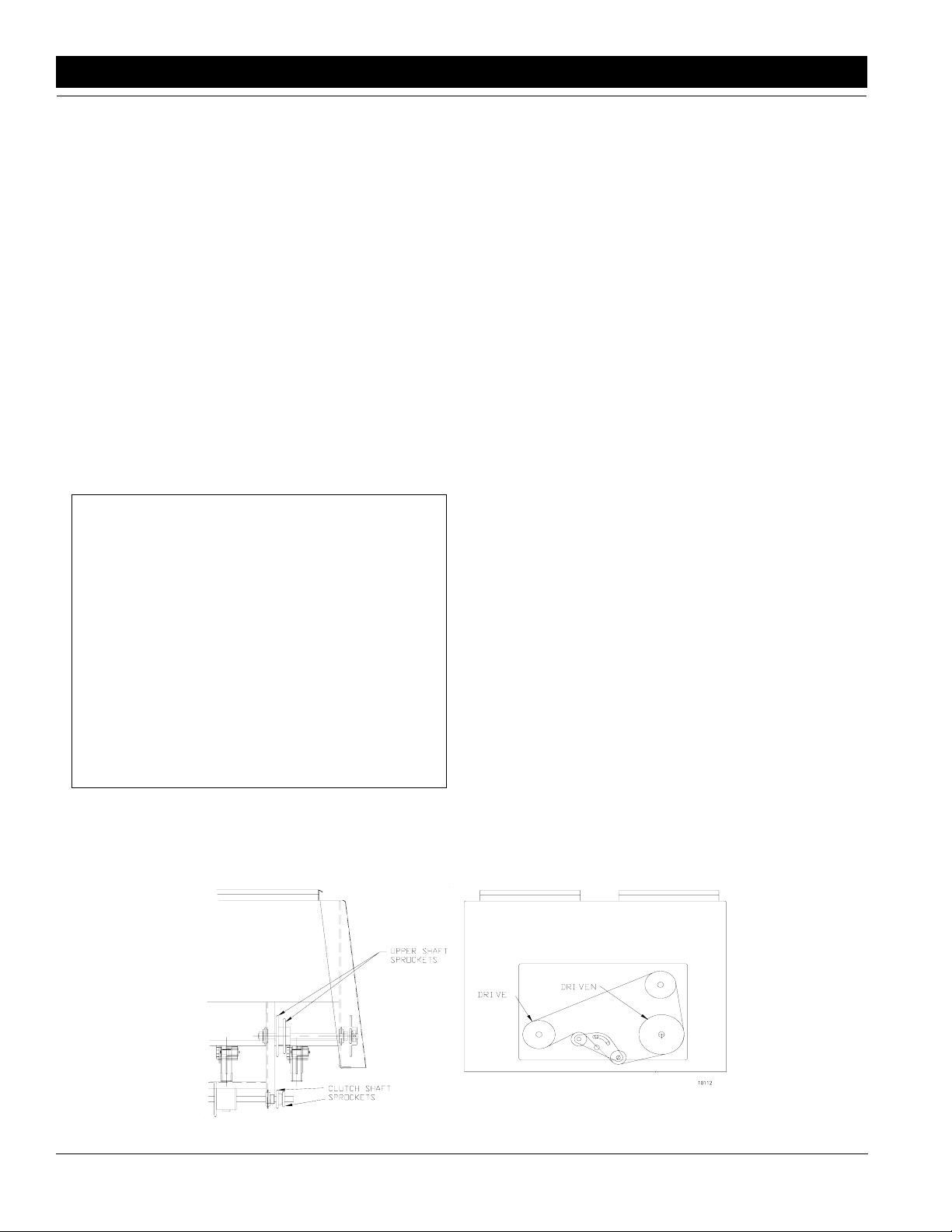
Refer to Figure 4-7:
2. To adjust you seeding rate, first find the row spacing
and the desired pounds/acre on the native grass
seed rate chart {see "Seeding Chart"}. Determine
which sprocket combination is required for the clutch
shaft sprocket and the upper shaft sprocket. This
sprocket combination is designated by the drive
types A, B, D, and D. From the chart, choose the
driver and driven sprocket combination that will deliver the desired native grass seed rate. In order to
change sprockets on the native grass unit, loosen
the idler arm and remove the chain, remove the
lynch pins on the driver and driven sprockets and rearrange the sprockets accordingly.
3. The pounds-per-acre in the seed chart is based on
drills having 9.00 x 24 drill rib tires.
4. After setting up your sprocket arrangement, complete the following procedure to calibrate the drill for
your specific seed type.
a. Fill three or more compartments at least one-
half full of seed at the outboard end of the drill.
b. Pull the seed tubes off the openers under the
compartments.
c. Lower the drill hydraulically to planting position
in order to activate the clutch.
d. Raise the drive (left) end tire off the ground us-
ing jack.
e. Place a container under the seed tubes to gath-
er the seed as it is metered
f. Rotate the tire until one acre has been tallied on
the acremeter. This will be approximately 422
rotations on a 10’ End Wheel No-Till Drill; and
592 rotations on a 7’ End Wheel No-Till Drill. Be
sure to check that the feeder cups have plenty of
seed coming into them.
g. Weigh the seed which has been metered. Di-
vide by the number of cups that were metered.
This will give you the ounces/pounds metered
by each feed cup. Multiply by the number of
openers on your drill to arrive at the total
11837
Sprocket Arrangement Diagram
Figure 4-7
20
EWNT7 and EWNT10 End Wheel No Till Drill 150-082M 4/17/2001
Great Plains Mfg., Inc.
10112
Page 23

Section 4 Adjustments
pounds-per-acre your drill would meter at that
setting. If this figure is different than desired,
change your sprocket arrangement accordingly.
5. You may want to repeat the calibration procedure if
the results of your calibration varies greatly from
what is listed on the seed rate chart.
IMPORTANT: Tire size and field conditions will also affect seeding rates. Be certain that your drill rib tires are
9.00 x 24 and that they have the proper inflation. When
ing acres drilled, amount of seed added to drill, and level
of seed in drill box. If you suspect that you are drilling
more or less than desired, and you have accurately calibrated the drill to your seed, you may need to adjust the
seeding rate slightly to compensate for your field conditions.
NOTE: Pounds per acre listed below are total
pounds of bulk seed {live and inert material}.
drilling, check the amount of seed you are using by not-
Native Grass Seed Rate Charts & Sprocket Selections
7’ END WHEEL NO-TILL DRILL
Clutch Upper
Row Shaft Shaft Drive
Spacing Spkt. Spkt. Type 15 35 15 30 19 35 19 30 24 35 15 19 30 35 19 19 35 30 19 15 35 24 30 19 35 19 30 15 35 15
12 35 A 2.4 2.8 3.1 3.6 3.9 4.4 4.8 5.6 6.6 7.1 8.2 8.9 10.4 11.2 13.1
12 30 B 2.8 3.3 3.6 4.2 4.5 5.2 5.6 6.6 7.7 8.3 9.6 10.4 12.1 13.1 15.3
10" 15 35 C 3.0 3.5 3.8 4.5 4.8 5.6 6.0 7.0 8.2 8.9 10.3 11.1 13.0 14.1 16.4
15 30 D 3.5 4.1 4.5 5.2 5.6 6.5 7.0 8.2 9.6 10.4 12.0 13.0 15.1 16.4 19.1
12 35 A 3.1 3.6 3.9 4.5 4.9 5.7 6.1 7.2 8.4 9.1 10.4 11.3 13.2 14.3 16.7
8" 12 30 B 3.6 4.2 4.5 5.3 5.7 6.6 7.2 8.4 9.7 10.6 12.2 13.2 15.4 16.7 19.5
7 1/2" 15 35 C 3.8 4.5 4.9 5.7 6.1 7.1 7.7 8.9 10.4 11.3 13.0 14.1 16.5 17.2 20.4
15 30 D 4.5 5.2 5.7 6.6 7.2 8.2 8.9 10.4 12.2 13.2 15.2 16.5 19.2 20.9 ----12 35 A 3.5 4.1 4.4 5.2 5.6 6.5 7.0 8.2 9.5 10.4 11.9 12.9 15.1 16.4 19.1
12 30 B 4.1 4.8 5.2 6.0 6.5 7.5 8.2 9.5 11.1 12.1 13.9 15.1 17.6 19.1 22.3
7" 15 35 C 4.4 5.1 5.5 6.5 7.0 8.1 8.8 10.2 11.9 13.0 14.9 16.4 20.5 23.8 -----
15 30 D 5.1 6.0 6.5 7.6 8.2 9.4 10.2 11.9 13.9 15.1 17.4 18.8 22.0 ----- -----
Driver
Driven
Driver
Driven
Driver
Driven
Driver
Driven
Driver
Driven
Driver
Driven
Pounds Per Acre
Driver
Driven
Driver
Driven
Driver
Driven
Driver
Driven
Driver
Driven
Driver
Driven
Driver
Driven
Driver
Driven
Driver
Driven
10’ END WHEEL NO-TILL DRILL
Clutch Upper
Row Shaft Shaft Drive
Spacing Spkt. Spkt. Type 15 35 15 30 19 35 19 30 24 35 15 19 30 35 19 19 35 30 19 15 35 24 30 19 35 19 30 15 35 15
Driver
Driven
Driver
Driven
Driver
Driven
Driver
Driven
Driver
Driven
Driver
Driven
Pounds Per Acre
Driver
Driven
Driver
Driven
Driver
Driven
Driver
Driven
Driver
Driven
Driver
Driven
Driver
Driven
Driver
Driven
Driver
12 35 A 2.4 2.8 3.1 3.6 3.9 4.4 4.8 5.6 6.6 7.1 8.2 8.9 10.4 11.2 13.1
12 30 B 2.8 3.3 3.6 4.2 4.5 5.2 5.6 6.6 7.7 8.3 9.6 10.4 12.1 13.1 15.3
10" 15 35 C 3.0 3.5 3.8 4.5 4.8 5.6 6.0 7.0 8.2 8.9 10.3 11.1 13.0 14.1 16.4
15 30 D 3.5 4.1 4.5 5.2 5.6 6.5 7.0 8.2 9.6 10.4 12.0 13.0 15.1 16.4 19.1
12 35 A 3.1 3.6 3.9 4.5 4.9 5.7 6.1 7.2 8.4 9.1 10.4 11.3 13.2 14.3 16.7
12 30 B 3.6 4.2 4.5 5.3 5.7 6.6 7.2 8.4 9.7 10.6 12.2 13.2 15.4 16.7 19.5
8" 15 35 C 3.8 4.5 4.9 5.7 6.1 7.1 7.7 8.9 10.4 11.3 13.0 14.1 16.5 17.2 20.4
15 30 D 4.5 5.2 5.7 6.6 7.2 8.2 8.9 10.4 12.2 13.2 15.2 16.5 19.2 20.9 ----12 35 A 3.3 3.8 4.2 4.9 5.3 6.1 6.6 7.7 8.9 9.7 11.2 12.1 14.1 15.3 17.9
12 30 B 3.8 4.5 4.9 5.7 6.1 7.1 7.7 8.9 10.4 11.3 13.1 14.1 16.5 17.9 20.9
7 1/2" 15 35 C 4.1 4.8 5.2 6.1 6.6 7.6 8.2 9.6 11.2 12.1 14.0 15.1 17.7 19.2 22.4
15 30 D 4.5 5.6 6.1 7.1 7.7 8.8 9.6 11.2 13.0 14.2 16.3 17.7 20.6 ----- ----12 35 A 3.5 4.1 4.4 5.2 5.6 6.5 7.0 8.2 9.5 10.4 11.9 12.9 15.1 16.4 19.1
12 30 B 4.1 4.8 5.2 6.0 6.5 7.5 8.2 9.5 11.1 12.1 13.9 15.1 17.6 19.1 22.3
7" 15 35 C 4.4 5.1 5.5 6.5 7.0 8.1 8.8 10.2 11.9 13.0 14.9 16.4 20.5 23.8 -----
15 30 D 5.1 6.0 6.5 7.6 8.2 9.4 10.2 11.9 13.9 15.1 17.4 18.8 22.0 ----- -----
4/17/2001 Great Plains Mfg., Inc.
EWNT7 and EWNT10 End Wheel No Till Drill 150-082M
-21
Driven
Page 24
Section 4 Adjustments
Planting Depth Adjustments
A no-till coulter is mounted independently and directly
ahead of each opener on the drill. Each coulter cuts
through heavy trash and/or cuts a groove in the firm soil
often encountered in no-till seeding conditions. The
coulters are mounted directly to the drill box frame. Consequently, the cutting depth of all coulters on the drill
change as the drill is raised and lowered. The cutting
depth of the coulters is controlled by an adjustable hydraulic depth stop on the master cylinder. Refer to "Hy-
draulic Depth Control" for information on how to make
this depth adjustment.) Those coulters which run directly in drill and tractor tire tracks may be individually lowered if desired. See "Individual Coulter Adjustment".
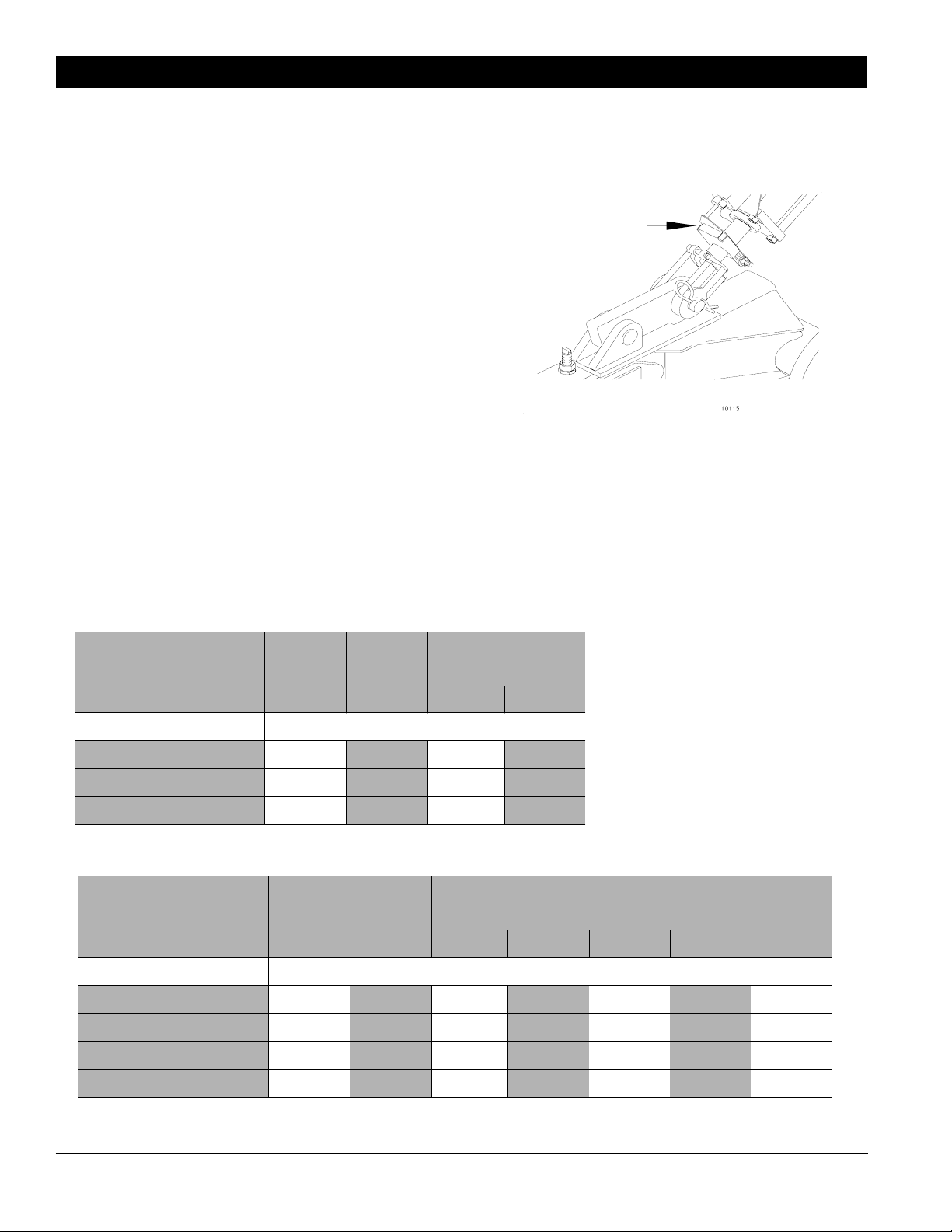
Coulter Hydraulic Depth Control
Refer to Figure 4-8:
The master lift cylinder on your drill is equipped with a
hydraulic depth control stop, Figure 4-8. This allows for
a variable adjustment from zero to maximum stroke
which controls the depth of your coulters. In order to adjust the stroke of the cylinder,retract the cylinder until the
coulters are penetrating at the desired depth required.
Next, loosen the bolt on the depth control actuator plate
and slide it up the cylinder until it stops against the
plunger of the control valve on the head of the cylinder.
You will now need to extend your cylinder slightly and
move the depth control actuator plate up to compensate
for the control valve plunger length.
10115
Master Cylinder With Depth Control Stop
Figure 4-8
Down Pressure Requirements
If more weight is required for your soil conditions, it
should be added to the weight bracket of the drill (optional equipment). Be sure the weights are equal at each
end. Refer to chart below for additional weights.
7’ Drill
Row
Spacing
Drill
Weight
Empty
Drill
Only
Drill With
*Weight
Bracket
Pounds Per Coulter
Great Plains Weight
Bracket & Weight
200# 600#
Required
7" 3800# 345# 375# 393# 421#
7 1/2" & 8" 3650# 365# 398# 418# N/A
10" 3350# 418# N/A N/A N/A
10’ Drill
Row
Spacing
Drill
Weight
Empty
Drill
Only
Drill With
*Weight
Bracket
Great Plains Weight Bracket & Weight Required
200# 600# 1000# 1200# 1400#
Pounds Per Coulter
7" 4500# 281# 302# 314# 340# 365# 377# 390#
7 1/2" 4350# 290# 312# 326# 352# 379# 392# N/A
8" 4200# 300# 324# 338# 367# 395# N/A N/A
10" 3750# 340# 371# 390# N/A N/A N/A N/A
*7’ Weight Bracket Part No. 150-010A
**10’ Weight Bracket Part No. 150-011A
22
EWNT7 and EWNT10 End Wheel No Till Drill 150-082M 4/17/2001
Great Plains Mfg., Inc.
Page 25
Section 4 Adjustments
Individual Opener & Coulter
When coulters and openers follow in tractor tire tracks
and individual coulters do not give satisfactory depth,
the coulter mounting bars can be lowered up to 1 1/2" by
loosening the mountingclamps and adjusting the coulter
and opener to the desired setting. Lowering openers
and coulters will not aid in penetrating hard soil. This is
achieved by adding weight to the drill. Refer to "Coulter
Down Pressure Requirements". To retighten the
clamps, snug the hex head mounting bolts until the ubolts are tight on each side of the spring bar. Tighten
nuts on u-bolts and then tighten hex head mounting
bolts.
NOTE: Transport clearance at these coulters will be
reduced in transport.
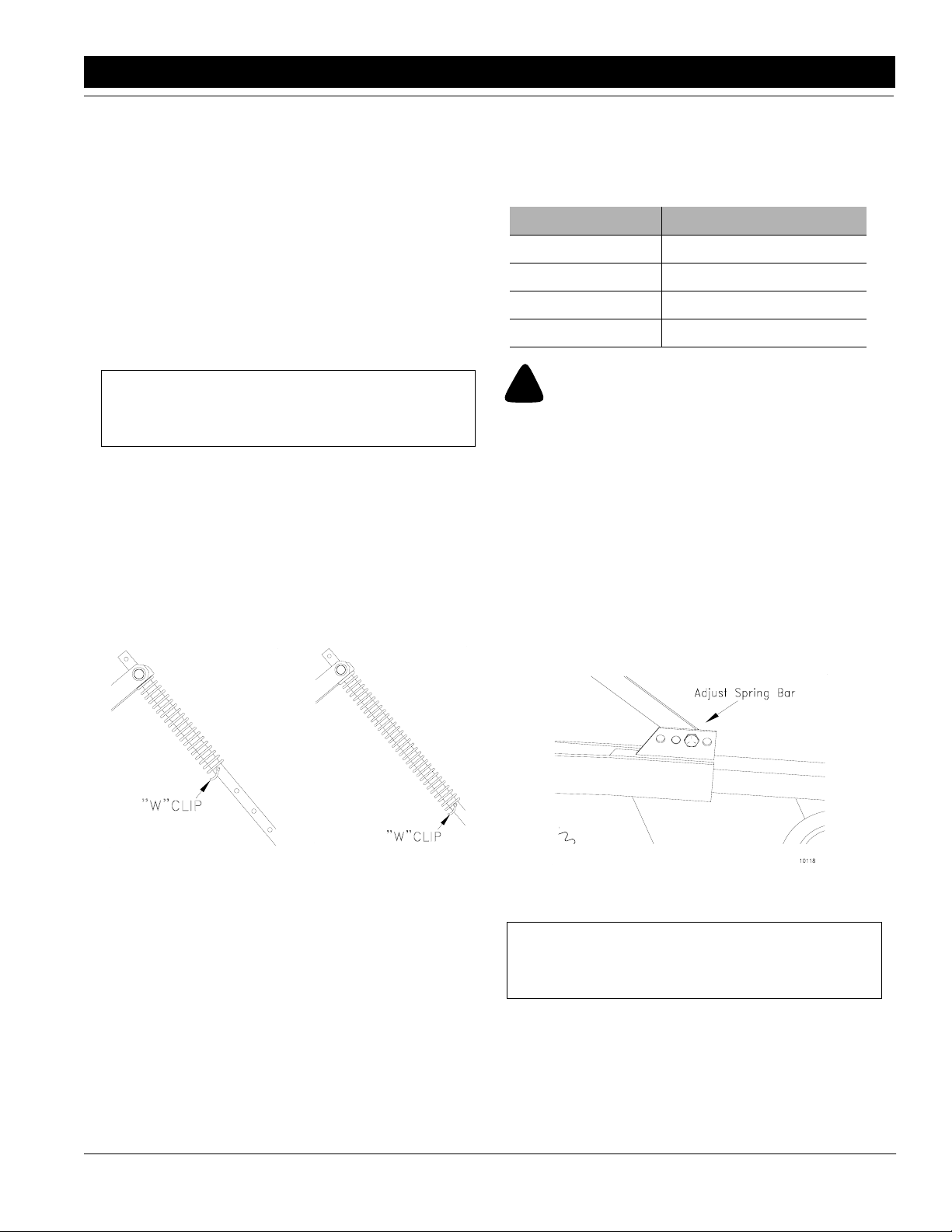
Disk Opener Spring Pressure Setting
Refer to Figure 4-9 & Figure 4-10:
Each opener spring can be individually adjusted for
down pressure. This is useful when penetrating hard
soil and for seeding in tractor tire tracks.
To adjust the pressure, remove the "W" clip at the bottom
of the spring and place it in a higher hole in the spring
rod for more pressure, Figure 4-9, or in a lower hole for
less pressure, Figure 4-10.
sirable to reduce the initial coulter preload to give the
coulters better impact protection. Refer to the following
chart for adjusting the initial coulter force setting.
Spring Length Initial Vertical Coulter Force
10 1/2" 175 lbs.
10 1/4" 300 lbs.
10" 400 lbs.
9 3/4" 525 lbs.
!
Any attempt to reset the coulter spring length shorter than
9 3/4" may contribute to premature failure of parts and warranty shall be voided.
CAUTION!
Individual Opener Height
Refer to Figure 4-11:
The opener depth may be adjusted at each opener.
Openers running in the tractor tire tracks, for example,
may require depth or down pressure adjustments.
The opener depth adjustment is made where the spring
bar connects to the top of the disk opener arm,
Figure 4-11. Connect the spring bar in a higher hole for
deeper opener location, or in a lower hole for a more
shallow opener location.
11836
Maximum Pressure
Figure 4-9
The coulter spring length is preset at the factory to 10",
which gives the coulters an initial operating force of 400
pounds. This setting is adequate for many difficult no-till
planting conditions. For lighter no-till conditions where
rocks or other obstructions are a problem, it may be de-
4/17/2001 Great Plains Mfg., Inc.
10129
Minimum Pressure
Figure 4-10
10118
Spring Bar Adjustment
Figure 4-11
NOTE: Transport clearance at the openers will be
reduced.
EWNT7 and EWNT10 End Wheel No Till Drill 150-082M
-23
Page 26
Section 4 Adjustments
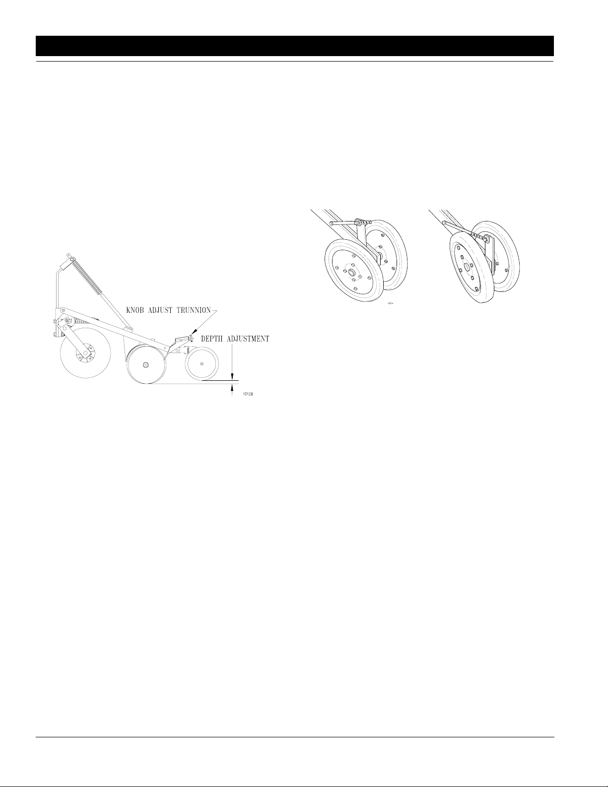
Opener Press Wheel Depth
Refer to Figure 4-12:
The depth of each opener can be adjusted by the position of the press wheel, Figure 4-12. After setting the
coulters to the desired depth by using the depth control
on the end wheel cylinder, see page 22, you can now adjust your press wheels up or down to achieve the correct
seeding depth.
With the drill level and lowered to planting position, adjust the knob and adjustment trunnion located above
each press wheel. This will vary the height of the press
wheel which automaticallychanges the seeding depth of
the opener. Simply rotate the knob until the seeding
depth is correct.
Press Wheel Angle
(2 x 13 Double "V" Press Wheels Only)
Refer to Figure 4-13 & Figure 4-14:
The camber angle of the 2" x 13" double "V" press
wheels may be adjusted by removing the angle bar adjustment pin and moving the angle bar. Moving the angle bar forward will cause the press wheels to pull more
soil over the seed, Figure 4-13. Moving the angle bar
back will cause the press wheel to pull less soil over the
seed, Figure 4-14
.
10074
Forward Position
Figure 4-13
11544
Rear Position
Figure 4-14
Opener Press Wheel Depth Adjustment
Figure 4-12
10128
24
EWNT7 and EWNT10 End Wheel No Till Drill 150-082M 4/17/2001
Great Plains Mfg., Inc.
Page 27

Section 5 Field Operations
Section 5 Field Operations
Drill Preparations
1. Be certain that your rib implement tires are 9.00 x 24
and that they have the proper inflation as listed on
page 6.
2. Load seed box with seed. You should use cleaned
seed to get the best results. You should always have
the drill hitched securely to a tractor and lowered before loading.
3. This drill can be transported with a full box of grain.
It is best not to do this unless necessary because
the increased weight does increase the chances for
problems on the road. Do not exceed 20 miles per
hour.
4. Your drill comes equipped with an acremeter and it
should be mounted on the right end of the jackshaft.
It will accumulate the total acres drilled with the drill.
In order to find out the acres covered, write down the
beginning reading and subtract it from the ending
reading for the total acres planted.
5. Make sure that the feed cup door adjustment handle
on each cup is set the same across the drill.
6. If you notice excessive cracking on large grain
seeds, adjust all feed cup door handles to a wider
setting. Refer to "Speed Change Box" on page 12.
7. Never back up with openers in ground. If you do,
check all openers to be sure none are clogged.
8. This drill is not designed to be turned sharply in the
field. Always lift the drill out of the ground when
turning at ends of field rows and other short-radius
turns.
9. Never allow anyone to ride on the drill.
10. Maximum seeding speed should vary according to
soil conditions.
11. Make sure the drive lockout hub (left end wheel) is
engaged, see Figure 3-3 on page 10, to allow the
gauge wheel drive to work.
!
Escaping fluid under pressure can have sufficient force to penetrate the skin. Check all hydraulic lines and hoses before applying pressure. Fluid escaping from a very small hole can be
almost invisible. Use paper or cardboard, not body parts, to
check for suspected leaks. If injured, seek medical assistance
from a doctor that is familiar with this type of injury. Foreign
fluids in the tissue must be surgically removed within a few
hours or gangrene will result.
CAUTION!
Operating Checklist
Check Reference
“Safety Rules” in this Manual “Section 1
“Hook-Up ” & "Operating" instructions in this
Manual
“Field Operations” in this Manual “Section 5 Field
Tire pressure “Tire Inflation
Feeder Cups for foreign matter
Engage drive hub (left end wheel) “Drive Lock Out
Rotate drive (left) wheel to make sure
the drive system operates smoothly.
Set speed change box for drive type
desired.
Rotate gauge wheels to make sure the
drive system operates smoothly.
Set seed rate. See “Seed Rate
Fertilizer agitator for foreign matter
Set fertilizer rate See “Fertilizer
Disconnect fertilizer drive chain when
fertilizer is not used.
Adjustment of disk opener scrapers for
ease in rotation.
Lubricate the drill as needed. See “Lubrica-
Seed & fertilizer tubes
Drill; innitially and periodically for loose
bolts, pins, and chains.
Safety Rules” on
Operations” on
Adjustment” on
Adjustments” on
Opener Spring
page 3
“Section 2
Assembly
Instructions &
Set-Up” on
page 6
page 25
Chart” on
page 6
Hub” on
page 10
“Drive Train
Operation” on
page 11
“Seed Rate
page 13
page 12.
Rate” on
page 19.
See “Disk
Pressure Set-
ting” on
page 23.
tion” on
page 26.
4/17/2001 Great Plains Mfg., Inc.
EWNT7 and EWNT10 End Wheel No Till Drill 150-082M
-25
Page 28

Section 6 Maintenance & Lubrication
Section 6 Maintenance & Lubrication
Maintenance
Proper servicing and adjustment is the key to the long
life of any farm implement. with careful and systematic
inspection, you can avoid costly maintenance, time and
repair.
1. After using yourdrill for several hours, check all bolts
to be sure they are tight.
2. Adjust idlers to remove excess slack from chains.
Clean and use chain lube on all roller chains as
needed.
3. Feed cup drive sprocket should be oiled in its square
bore. Move feed cup adjustment lever away from the
sprocket as far as possible in order to get the oil back
into the square.
4. Always maintain the proper air pressure in the rib
implement tires.
5. Disk scrapers should be kept properly adjusted.
6. Replace any worn, damaged or illegible safety decals by obtaining new decals from your Great Plains
Dealer.
Fertilizer Unit
It is recommended that the fertilizer unit be thoroughly
cleaned every two or three days during operating season and before putting the drill in storage for an extended period of time.
4. Feed cup drive sprocket hub should be oiled in its
square bore. Squirt oil on to the square feed cup
shaft and move feed cup adjustment lever back and
forth in order to get the oil back into the square. This
is most important before putting the drill in storage.
5. Store the drill inside if possible for longer drill life.
6. When in storage, lower the drill with openers on a
board or hard surface. Apply a light coat of oil to exposed cylinder rods.
Lubrication
Lubrication Symbols
50
Lubrication is required every 50 hours of operation.
10
Lubrication is required every 10 hours of operation.
As
Required
NOTE: Fertilizer build up on the rotor will affect the
fertilizer application rate. Drop fertilizer tray doors
by releasing latches on back of tray. Using a highpressure water system, thoroughly clean the fertilizer tray, gate openings, and rotor. Rotate end sprocket to ensure cleaning the entire fertilizer metering
star at each drop location.
Storage
1. Clean the drill as necessary. Be sure that the seed
boxes are completely cleaned before storing.
2. Lubricate and adjust all roller chains.
3. Lubricate all pivots as indicated in the following Illustrations.
Use a multipurpose spray lube. Use as required.
Do not over lubricate.
Seasonally
Lubrication is required ____.
NOTE: Your speed change box has been lubricated
at the factory and requires no additional service. If
maintenance is required, clean and lubricate your
speed change box with lithium based wheel bearing
grease. (Types - Texaco, MARFAK HD2, Penzoil No.
705 or equivalent.)
26
EWNT7 and EWNT10 End Wheel No Till Drill 150-082M 4/17/2001
Great Plains Mfg., Inc.
Page 29

Section 6 Maintenance & Lubrication
13877
Seasonally
End Wheel Hub Bearings
Type of Lubrication: Multipurpose Grease
8-10
Wheel Arm Pivot Castings
13878
13881
Type of Lubrication: Multipurpose Grease
Seasonally
Coulter Hub Bearings
Type of Lubrication: Multipurpose Grease
Quantity = Coat Generously
Seasonally
Coulter Arm Pivot
13880
4/17/2001 Great Plains Mfg., Inc.
Type of Lubrication: Multipurpose Grease
Quantity = Coat Generously
EWNT7 and EWNT10 End Wheel No Till Drill 150-082M
-27
Page 30
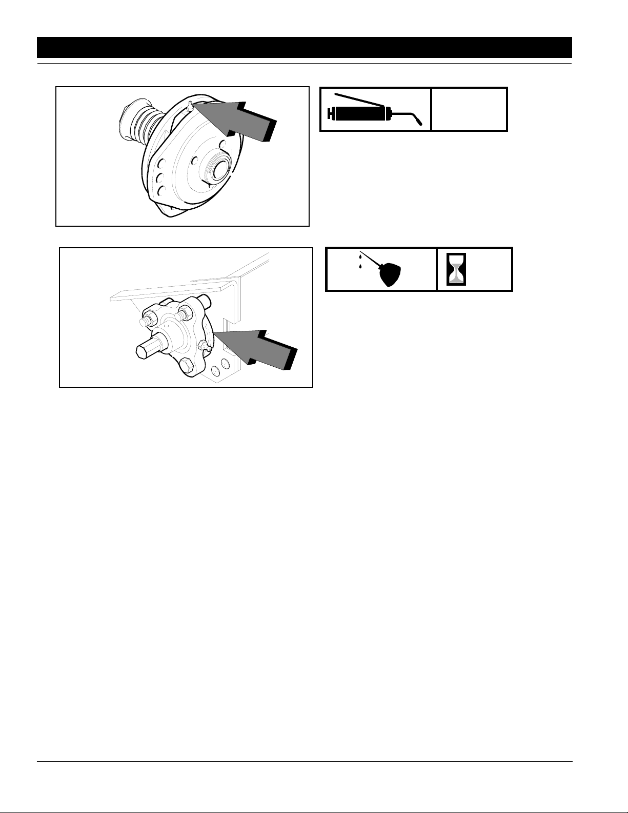
Section 6 Maintenance & Lubrication
Seasonally
Clutch Cam
Type of Lubrication: Multipurpose Grease
13881
24
Fertilizer Felt Seal
Type of Lubrication: Multipurpose Grease
Quantity = Coat Generously
13882
28
EWNT7 and EWNT10 End Wheel No Till Drill 150-082M 4/17/2001
Great Plains Mfg., Inc.
Page 31

Section 7 Troubleshooting
Section 7 Troubleshooting
Problem Solution
Uneven seed spacing or uneven stand
Opener disks not turning freely
Actual seeding rate is different than
desired
Check for plugging in feed cup.
Check to see if seed tubes are plugged.
Reduce ground speed.
Check opener disks to see they turn freely.
Use faster drive type speed and close feed cup flutes to a more narrow position.
Spring pressure on openers could be improperly adjusted causing opener
to not penetrate low spots.
Check for trash or mud build-up on Seed-Lok Wheel.
Check for trash or mud build-up on disk scraper. Readjust scraper.
Check to see if scraper is adjusted too tight and is restricting disk movement.
Check disk bearings.
Check opener frame for possible damage.
If opener disks turn freely by hand but not in field, lessen down pressure on
disk opener.
Check press wheel adjustment for seeding depth.
Check tire pressure. Proper inflation is listed in the “Tire Inflation Chart",
Section 2, page 6.
Check gauge wheel size. Proper size is 9.00L x 24".
Seed treatment will affect seeding rate if the chemicals build up in seed cup.
Unless cleaned regularly, this build-up can cause breakage of the feed shaft.
Excessive seed cracking
Acremeter doesn’t measure accurately
Uneven seeding depth
Press Wheel not compacting the soil
as desired
Check drill box setting.
See Operator’s Manual for instructions on calculating seed rate.
Use slower drive speed and open flutes in feed cup to a wider position.
Position feed cup handles to a lower notch.
Check tire pressure. Proper inflation is listed in the "Tire Inflation Chart".
Section 2, page 6.
Check gauge wheel tire size. Proper size is 9.00L x 24".
Check planting operation for excessive overlap or gaps between passes.
Loose soil conditions and slippage will cause variations in acres registered.
To check accuracy of acremeter, see Section 4, page 12 in "Seed Rate
Adjustments".
Check to be sure your acremeter is for your width of drill.
See section on depth adjustments.
Reset press wheel depth, see seeding and press wheel adjustments sections.
2" x 13" Double "V" press wheel angles may need to be adjusted.
Down pressure on disk openers is not enough.
4/17/2001 Great Plains Mfg., Inc.
EWNT7 and EWNT10 End Wheel No Till Drill 150-082M
-29
Page 32

Section 7 Troubleshooting
Problem Solution
Grain box not emptying evenly
Press wheel or openers plugging
Raising and lowering drill is rough or
uneven
Feed cup sprockets locked up or
twisted feed drive shaft
Certain models do not have the same number of seed cups between each
divider of bulkhead. The section with the larger number of cups will empty
sooner.
Drilling in damp or wet conditions may increase this problem.
Reduce down pressure on openers.
Do not back up drill in the field, or stop and allow drill to roll backwards with
openers in the ground.
If using double "V" press wheels, adjust angle bar.
Check Seed-Lok Wheel.
Lubricate wheel arm pivot casting.
Check hydraulic fittings or leaks.
Rephasing cylinders not properly bled. Refer to "Hydraulic Hook-Up" on
page ??. When raising the drill at the end of the field, the lifting cylinders
should be fully extended to insure that they are always rephased. If drill is
only raised enough to lift openers out of ground, lift cylinders may eventually get out of sequence and cause uneven seeding depth.
Check for foreign matter lodged in one or more feeder cup sprockets.
Liquid insecticide from seed has dried within the feed cups. Remove the
build up by disassembling each feed cup and scrape the foreign substance
from the turning surfaces. NOTE: Liquid insecticide should be applied with
caution and care should be taken to clean the feed system after drilling
treated seeds.
Coulters not going deep enough
Coulters and drill going to deep
Hoses plugging in no-till conditions
Check weight chart on page 22 and add additional weight.
Lower coulter spring bars on tool bar. {Only in tire tracks.}
Check cylinder depth stop, refer to page 22.
Check weight chart on page 22and remove weight if necessary.
Set press wheels to a shallower depth.
Check cylinder depth stop, refer to page 22.
Drill at a slight angle to the rows.
30
EWNT7 and EWNT10 End Wheel No Till Drill 150-082M 4/17/2001
Great Plains Mfg., Inc.
Page 33
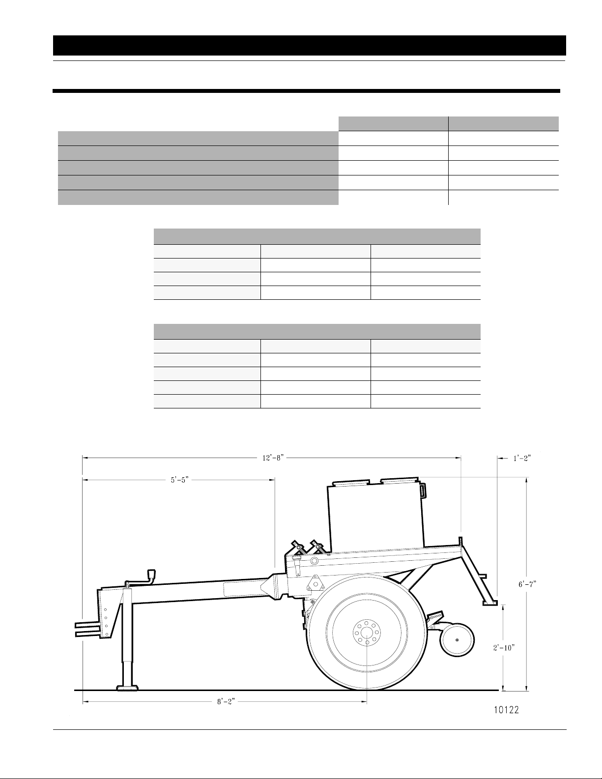
Section 8 Specifications & Warranty
Section 8 Specifications & Warranty
Fertilizer Attachment Capacity:
Seed Capacity of Fertilizer/Native Grass Box:
Drill Row Spacing No. Of Openers Drill Weight
7" 11 *3800
7 1/2" & 8" 10 *3650#
10" 8 *3350#
Transport Width
Tire Size:
Box Capacity:
7’ End Wheel No-Till
7’ End Wheel No-Till 10’ End Wheel No-Till
9’ 8" 12’ 6"
9.00 x 24 9.00 x 24
17.1 Bushels 23.75 Bushels
553 Pounds 741 Pounds
12.7 Bushels 17 Bushels
10’ End Wheel No-Till
Drill Row Spacing No. Of Openers Drill Weight
7" 16 *4500#
7 1/2" 15 *4350#
8" 14 *4200#
10" 11 *3750#
*Approximate weights for machines equipped with double disk openers, 2" x
13" single press wheels, step and hydraulic cylinders.
4/17/2001 Great Plains Mfg., Inc.
EWNT7 and EWNT10 End Wheel No Till Drill 150-082M
10122
-31
Page 34

Section 8 Specifications & Warranty
Great Plains warrants to the original purchaser that this Great
Plains product will be free from defects in material and workmanship for a period of one year, from the date of delivery to the end
user,
when used as intended and under normal service and conditions
for personal use; 90 days for commercial or rental purposes. This
Warranty is limited to the replacement of any defective part by and
the installation by the dealer of any such replacement part. reserves the right to inspect any equipment or parts which are
claimed to have been defective in material or workmanship.
This Warranty does not apply to any part or product which in
Great Plains’s judgement shall have been misused or damaged by
accident or lack of normal maintenance or care, or which has been
repaired or altered in a way which adversely affects its performance or reliability, or which has been used for a purpose for which
the product is not designed.
Warranty
Claims under this Warranty must be made to the dealer which
originally sold the product and all warranty adjustments must be
made through such dealer. Great Plains reserves the right to make
changes in materials or design of the product at any time without
notice.
This Warranty shall not be interpreted to render Great Plains liable for damages of any kind, direct, consequential, or contingent,
to property. Furthermore, Great Plains shall not be liable for damages resulting from any cause beyond its reasonable control. This
Warranty does not extend to loss of crops, losses caused by harvest delays or any expense or loss for labor, supplies, rental machinery or for any other reason.
No other warranty of any kind whatsoever, express or implied, is made with respect to this sale; and all implied warranties of merchantability and fitness for a particular purpose
which exceed the obligations set forth in this written warranty
are hereby disclaimed and excluded from this sale.
This Warranty is not valid unless registered with Great Plains
within 10 days from the date of delivery to the end user.
4/25/06 Great Plains Mfg., Inc.
EWNT7 and EWNT10 End Wheel No Till Drill 150-082M
-32
 Loading...