

Page 1

Update M a n u a l
7’ & 10’ End Wheel No-Till
Clutch Linkage
Manufacturing, Inc.
P.O. Box 218
Assaria, Kansas 67416
Effective 5/3/96 152-156M
Page 2

General Information
General Information
Important Notice
Great Plains Manufacturing, Inc. provides this publication “as is” without warranty of any kind, either express
or implied, while every precaution has been taken in the
preparation of this manual, Great Plains Manufacturing,
Inc. assumes no responsibility for errors or omissions.
Neither is any liability assumed for damages resulting
from the use of the information contained herein. Great
Plains Manufacturing, Inc. reserves the right to revise
This Operator’s Manual applies to No-Till Drill Clutch Linkage Update Kit for:
Description 36’ Drill
7’ Seed Clutch Update 152-151A
7’ Fert. NG Clutch Update 152-152A
10’ Seed Clutch Update 152-154A
10’ Fert. & NG Clutch Update 152-155A
and improve its products as it sees fit. This publication
describes the state of this product at the time of its publication, and may not reflect the product at all times in the
future. Printed in the United States of America.
For your convenience, record your Model Number and
the Date Purchased in the spaces provided below. Have
this information before you when calling Great Plains
Manufacturing, Inc.
Owner’s Information
Name: _____________________________________
Address ____________________________________
City _______________ State_____Zip ___________
Phone _____________________________________
Name of Dealership___________________________
Dealer’s Name ______________________________
Address ____________________________________
City _______________ State_____Zip ___________
7’ & 10’ End Wheel No-Till Clutch Linkage 152-156M 5/3/96Great Plains Mfg., Inc.
Phone _____________________________________
Model Number ______________________________
Date Purchased _____________________________
Page 3
Using this Manual
Table of Contents
Introduction . . . . . . . . . . . . . . . . . . . . . . . . . . . . . . . 1
Using this Manual . . . . . . . . . . . . . . . . . . . . . . . . . . . 1
Section 1 Safety Rules . . . . . . . . . . . . . . . . . . . . . . . 2
Section 2 Assembly & Set-Up . . . . . . . . . . . . . . . . . 2
Torque Values Chart . . . . . . . . . . . . . . . . . . . . . . 2
Before You Start . . . . . . . . . . . . . . . . . . . . . . . . . 3
Old 7’ Clutch Linkage Disassembly . . . . . . . . . . . 3
Introduction
This manual has been prepared to instruct you in the
safe and efficient operation of your Clutch Linkage Up
date Kit. Read and follow all instructions and safety
precautions carefully.
The parts on your Clutch Linkage Update Kit have been
specially designed and should only be replaced with
genuine Great Plains parts. Therefore, should your
Clutch Linkage Update Kit require replacement parts go
to your Great Plains Dealer.
The right hand and left hand as used throughout this
manual is determined by facing in the direction the ma
chine will travel when in use unless otherwise stated.
New 7’ Clutch Linkage Assembly . . . . . . . . . . . . 4
Before You Start . . . . . . . . . . . . . . . . . . . . . . . . . 5
Old 10’ Clutch Linkage Disassembly . . . . . . . . . . 5
New 10’ Clutch Linkage Assembly . . . . . . . . . . . 6
Section 3 Parts Illustrations. . . . . . . . . . . . . . . . . . . 8
7’ Clutch Linkage Update Assembly. . . . . . . . . . . 9
10’ Clutch Linkage Update Assembly. . . . . . . . . 11
Watch for the following safety notations throughout your
Operators Manual:
-
!
DANGER!
Indicates an imminently hazardous situation which, if
not avoided, will result in death or serious injury. This
signal word is limited to the most extreme situations.
!
WARNING!
-
Indicates a potentially hazardous situation which, if not
avoided, could result in death or serious injury.
!
The SAFETY ALERT SYMBOL indicates that there is a
potential hazard to personal safety involved and extra
safety precautions must be taken. When you see this
symbol, be alert and carefully read the message that fol
lows it. In addition to design and configuration of
equipment; hazard control and accident prevention are
dependent upon the awareness, concern, prudence and
proper training of personnel involved in the operation,
transport, maintenance and storage of equipment.
Using this Manual
For your safety and to help in developing a better understanding of your equipment we highly recommend that
you read the operator sections of this manual. Reading
these sections not only provides valuable training but
also familiarizes you with helpful information and its lo
5/3/96
Great Plains Mfg., Inc.
!
CAUTION!
Indicates a potentially hazardous situation which, if not
avoided, may result in minor or moderate injury. It may
also be used to alert against unsafe practices
NOTE: Indicates a special point of information which
requires your attention.
IMPORTANT: Indicates additional information is provided that is necessary to prevent possible damage to the
equipment only.
cation. The parts sections are for reference only and
don’t require cover to cover reading. After reviewing the
manuals store them in a dry, easily accessible location
for your future reference.
-
7’ & 10’ End Wheel No-Till Clutch Linkage 152-156M
.
-2
Page 4
Section 2 Assembly & Set-Up
Section 1 Safety Rules
Most accidents are the result of negligence and carelessness, usually caused by failure of the operator to follow
simple but necessary safety precautions. The following
safety precautions are suggested to help prevent such
accidents. The safe operation of any machinery is a big
concern to consumers and manufacturers. Your Clutch
Linkage Update Kit have been designed with many builtin safety features. However, no one should operate this
product before carefully reading this Operators Manual.
equipment when it is in operation!
3. Before working on, servicing or making adjustments on the drill, ALWAYS disengage power, shut off engine, make sure all moving parts have stopped, and all pres sure in the system is relieved.
4. Escaping fluid under pressure can have sufficient force
to penetrate the skin. Check all hydraulic lines and hoses
before applying pressure. Fluid escaping from a very
small hole can be almost invisible. Use paper or card
board, not body parts, to check for suspected leaks. If in-
General Operation & Repair
1. DO NOT exceed 20 mph transport speed.
2. Areas of this drill can be dangerous and can cause bodily
harm if not properly used or guarded. Stay away from
jured, seek medical assistance from a doctor that is
familiar with this kind of injury. Foreign fluids in the tis
sue must be surgically removed within a few hours or
gangrene will result.
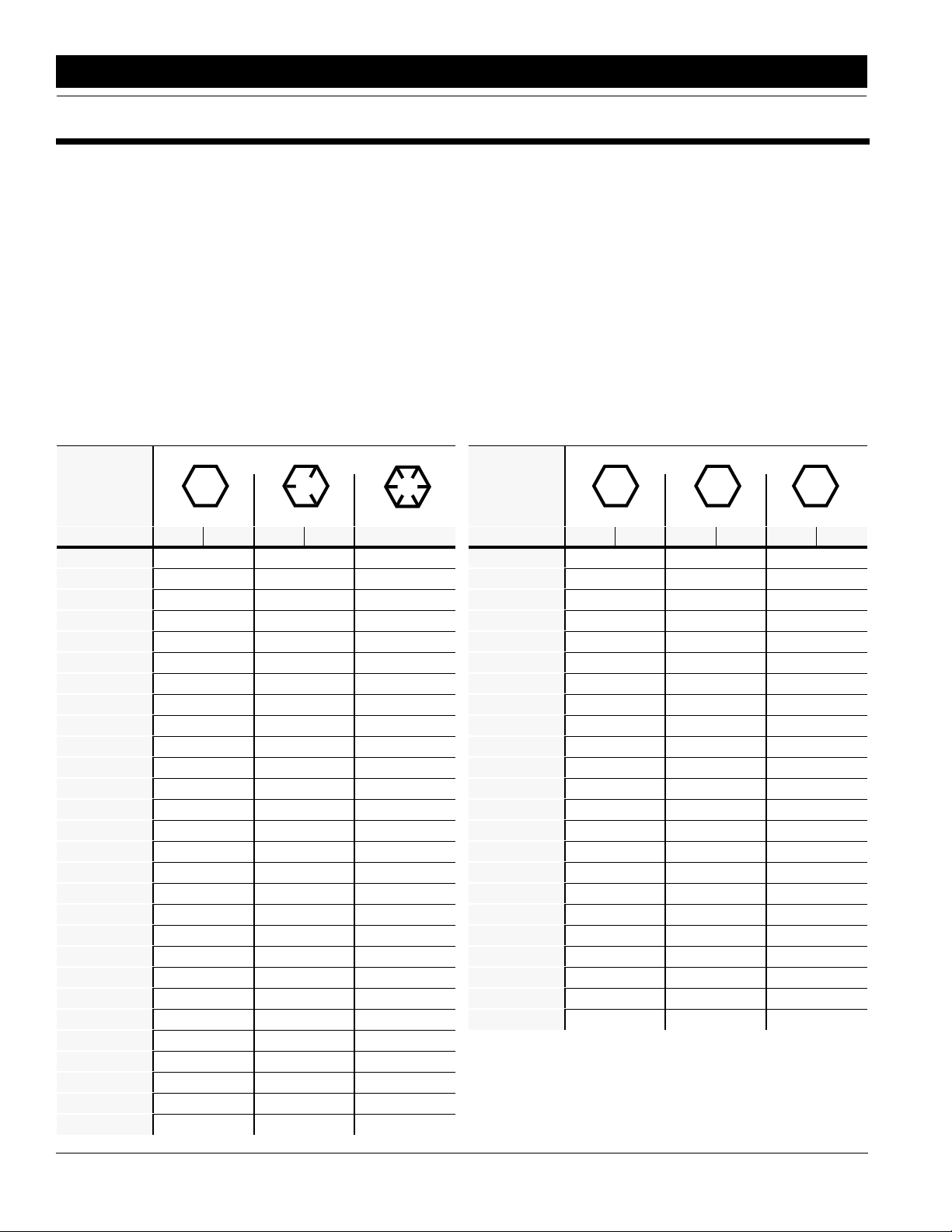
Torque Values Chart for Common Bolt Sizes
Bolt Head Identification
Bolt Size
(Inches)
1
in-tpi
Section 2 Assembly & Set-Up
1/4" - 20 7.4 5.6 11 8 16 12 M 5 X 0.8 4 3 6 5 9 7
1/4" - 28 8.5 6 13 10 18 14 M 6 X 1 7 5 11 8 15 11
5/16 - 18 15 11 24 17 33 25 M 8 X 1.25 17 12 26 19 36 27
5/16" - 24 17 13 26 19 37 27 M 8 X 1 18 13 28 21 39 29
3/8" - 16 27 20 42 31 59 44 M10 X 1.5 33 24 52 39 72 53
3/8" - 24 31 22 47 35 67 49 M10 X 0.75 39 29 61 45 85 62
7/16" - 14 43 32 67 49 95 70 M12 X 1.75 58 42 91 67 125 93
7/16" - 20 49 36 75 55 105 78 M12 X 1.5 60 44 95 70 130 97
1/2" - 13 66 49 105 76 145 105 M12 X 1 90 66 105 77 145 105
1/2" - 20 75 55 115 85 165 120 M14 X 2 92 68 145 105 200 150
9/16" - 12 95 70 150 110 210 155 M14 X 1.5 99 73 155 115 215 160
9/16" - 18 105 79 165 120 235 170 M16 X 2 145 105 225 165 315 230
5/8" - 11 130 97 205 150 285 210 M16 X 1.5 155 115 240 180 335 245
5/8" - 18 150 110 230 170 325 240 M18 X 2.5 195 145 310 230 405 300
3/4" - 10 235 170 360 265 510 375 M18 X 1.5 220 165 350 260 485 355
3/4" - 16 260 190 405 295 570 420 M20 X 2.5 280 205 440 325 610 450
7/8" - 9 225 165 585 430 820 605 M20 X 1.5 310 230 650 480 900 665
7/8" - 14 250 185 640 475 905 670 M24 X 3 480 355 760 560 1050 780
1" - 8 340 250 875 645 1230 910 M24 X 2 525 390 830 610 1150 845
1" - 12 370 275 955 705 1350 995 M30 X 3.5 960 705 1510 1120 2100 1550
1-1/8" - 7 480 355 1080 795 1750 1290 M30 X 2 1060 785 1680 1240 2320 1710
1 1/8" - 12 540 395 1210 890 1960 1440 M36 X 3.5 1730 1270 2650 1950 3660 2700
1 1/4" - 7 680 500 1520 1120 2460 1820 M36 X 2 1880 1380 2960 2190 4100 3220
1 1/4" - 12 750 555 1680 1240 2730 2010
1 3/8" - 6 890 655 1990 1470 3230 2380
1 3/8" - 12 1010 745 2270 1670 3680 2710
1 1/2" - 6 1180 870 2640 1950 4290 3160
1 1/2" - 12 1330 980 2970 2190 4820 3560
Grade 2 Grade 5
N · m2ft-lb3N · m ft-lb N · m ft-lb mm x pitch
Grade 8
Bolt Size
(Metric)
4
N · m ft-lb N · m ft-lb N · m ft-lb
1
in-tpi = nominal thread dia. in inches-threads per inch
2
N· m = newton-meters
3
ft-lb= foot pounds
4
mm x pitch = nominal thread dia. in millimeters x thread pitch
Bolt Head Identification
5.8 8.8 10.9
Class 5.8 Class 8.8 Class 10.9
-
-
-
-1
7’ & 10’ End Wheel No-Till Clutch Linkage 152-156M 5/3/96
Great Plains Mfg., Inc.
Page 5
Assembly
Before You Start
Read and understand the owners manual for your
Clutch Linkage Update Kit. A basic understanding of
how the kit works will aid in the assembly, setup and op
eration of your drill.
Before attempting to assemble the Clutch Linkage Update Kit, use the following as a checklist. Having all the
needed parts and equipment readily at hand will speed
up your assembly task and will make the job as safe as
possible.
❑ Check for all kit components and hardware.
❑ If a bolt, pin or other component has been removed,
or if you are unsure about where it is used, refer to
the parts section of this manual to identify it.
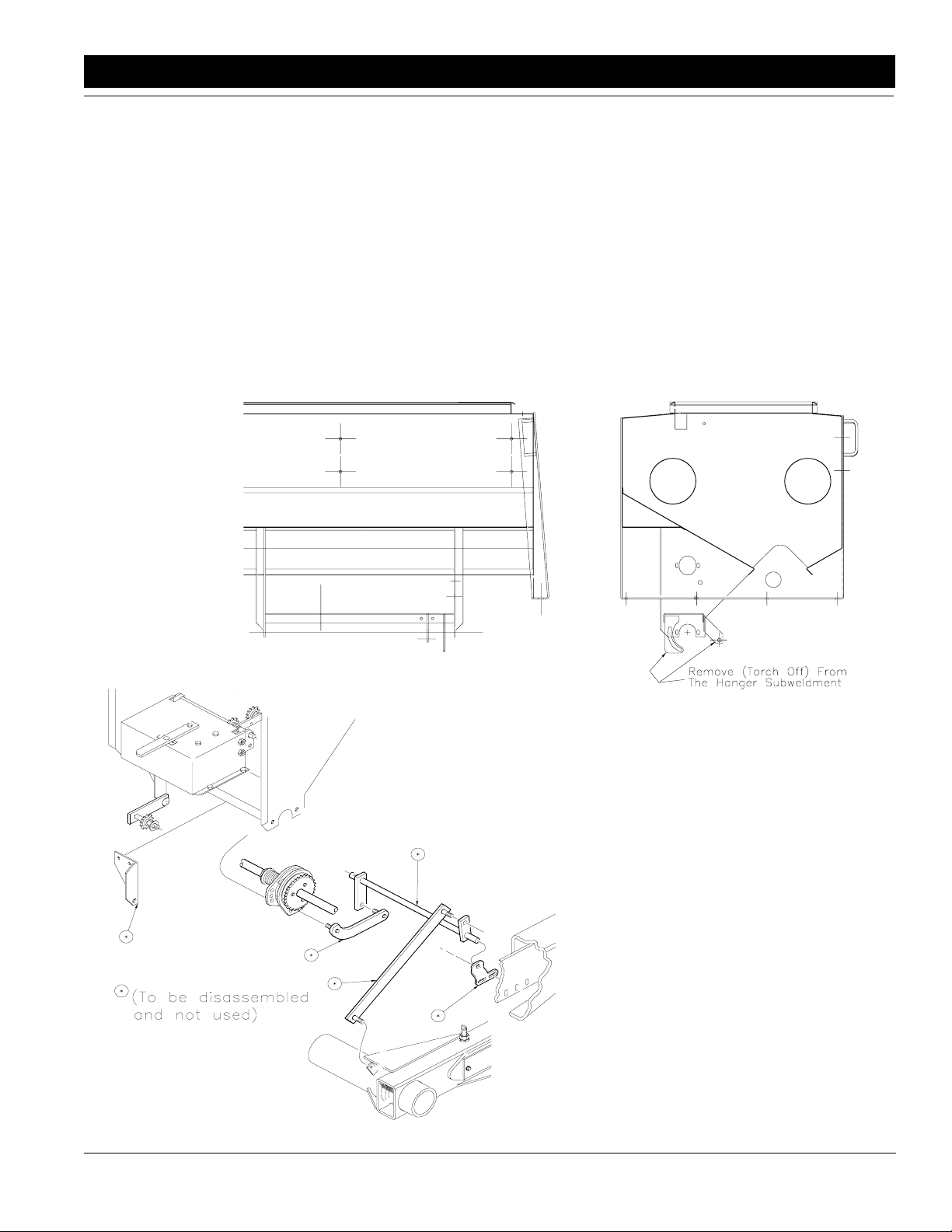
Old 7’ End Wheel No-Till Clutch Linkage Disassembly
Refer to Figure 2-1:
Start by disassembling the clutch linkage. Unbolt the
clutch shaft from the shaft supports, but leave the clutch
assembly together. Refer to
be used. After all the linkage is disassembled, torch off
the clutch mounting tab and the clutch lever bracket from
the hanger sub-weldment.
Figure 2-1 for what will not
13803
Old 7’ End Wheel No-Till Disassembly
Figure 2-1
Parts Not Used
Figure 2-2
5/3/96
Great Plains Mfg., Inc.
13802
7’ & 10’ End Wheel No-Till Clutch Linkage 152-156M
0
Page 6

Assembly
New 7’ End Wheel No-Till Clutch Linkage Assembly
Refer to Figure 2-1:
Sliding the inside retaining washers
(#22) and the pivot bushing (#8)
onto the clutch rod weldment (#21).
Then insert this assembly into the
clutch rod support (#3) and add the
pivot tube (#9), push arm (#5), out
side retaining washers (#22) and
cotter pins (#23) as shown. Fasten
the clutch rod support (#3) to the
hanger using 5/16"-18 x 1" bolts
(#13), 5/16’ washers & nuts,
(#14,18,19) and a 3/8" x 1 1/4" bolt
(#12) and 3/8" hardware (#16,21).
NOTE: The push arm (#5)
must be in line with the arm
on the clutch rod (#2).
-
Attach the clutch arm (#6) to the
mount tab on the gauge wheel and
the clutch rod push arm (#5) using
3/8-16 lock nuts (#15).
Fasten the clutch tab (#10) to the
clutch slide plate using 3/8"-16 x 1"
bolts (#11) with 3/8-16 Nylock nuts
(#17).
NOTE: Assemble the clutch tab adjustment (#7)
with the ear of the clutch tab (#10) in the adjustment
slot.
Add the clutch tab adjustment (#7) to the clutch rod support (#3) using 3/8"-16 x 1 1/4" bolts (#12) and 3/8"
hardware (#16,20,21) but do not fully tighten.
Attach the link pull arm (#4) to the clutch and to the
clutch rod (#2) with a 3/8"-16 Nylock nut (#15). Adjust
the tab plate (#7) to correctly engage/disengage the
clutch assembly during normal field operations. This can
be done by raising and lowering the hydraulics and care
fully watching the engaging/disengaging of the clutch.
After it is adjusted, tighten the adjustment plate (#7) in
place.
13804
New 7’ End Wheel No-Till Clutch Linkage Assembly
Figure 2-3
-
1
7’ & 10’ End Wheel No-Till Clutch Linkage 152-156M 5/3/96
Great Plains Mfg., Inc.
Page 7

Assembly
Before You Start
Read and understand the owners manual for your
Clutch Linkage Update Kit. A basic understanding of
how the kit works will aid in the assembly, setup and op
eration of your drill.
Before attempting to assemble the Clutch Linkage Update Kit, use the following as a checklist. Having all the
needed parts and equipment readily at hand will speed
up your assembly task and will make the job as safe as
possible.
❑ Check for all kit components and hardware.
❑ If a bolt, pin or other component has been removed,
or if you are unsure about where it is used, refer to
the parts section of this manual to identify it.
Old 10’ End Wheel No-Till Clutch Linkage Disassembly
Refer to Figure 2-4:
Start by disassembling the clutch linkage. Unbolt the
clutch shaft from the shaft supports, but leave the clutch
assembly together. Refer to
be used. After all the linkage is disassembled, torch off
the clutch mounting tab and the clutch lever bracket from
the hanger sub-weldment.
Figure 2-5 for what will not
13805
Old 10’ End Wheel No-Till Disassembly
Figure 2-4
5/3/96
Great Plains Mfg., Inc.
Parts Not Used
Figure 2-5
13806
7’ & 10’ End Wheel No-Till Clutch Linkage 152-156M
2
Page 8
Assembly
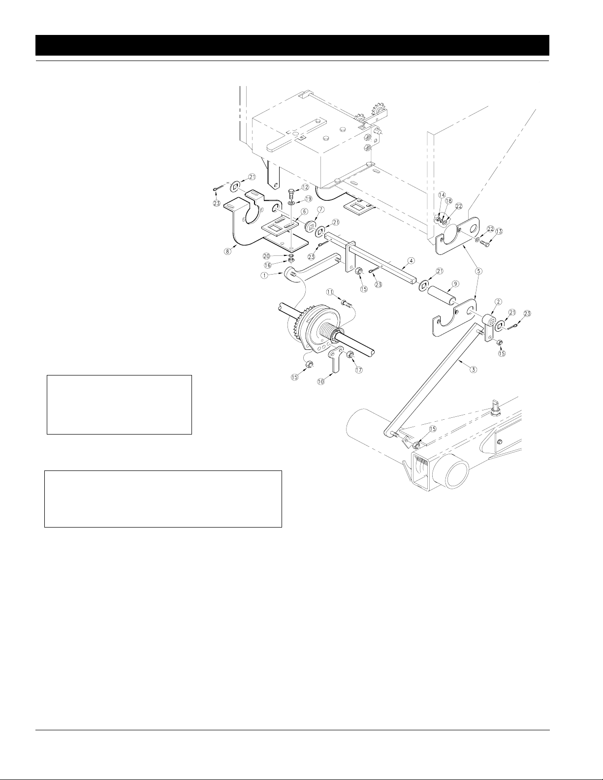
New 10’ End Wheel No-Till Clutch Linkage Assembly
Refer to Figure 2-6:
Attach the clutch mounting plate
(#8) to the bottom of the hanger
sub-weldment using the existing
hardware that fastens the gearbox
on. Then fasten the clutch rod sup
port (#5) to the hanger using
5/16"-18 x 1" bolts (#13), 5/16"
washers, & nuts.(#14,18,22). Preassemble the clutch rod weldment
(#4), and inside cotter pin (#23).
Slide the inside retaining washers
(#21) & pivot bushing (#7) onto the
clutch rod. Insert this assembly into
the hole of the mounting plate (#8)
and rod supports (#5). Hold this in
place with a retaining washer (#21)
and cotter pin (#23). Slip the clutch
rod spacer (#9) over the outside end
of the clutch rod and through the
support plate. Retain it in place with
the rod push arm, (#2) retaining
washer (#21) and cotter pin (#23).
-
NOTE: The push arm (#2)
must be in line with the arm on
the clutch rod (#4).
Fasten the clutch tab (#10) to the clutch slide plate using
3/8"-16 x 1" bolts (#11) with 3/8"-16 Nylock nuts (#17).
NOTE: Assemble the clutch tab adjustment (#6)
with the ear of the clutch tab (#10) in the adjustment
slot.
Add the clutch tab adjustment (#6) to the clutch mounting plate (#8) using 3/8"-16 x 1 1/4" bolts (#12) and 3/8"
hardware (#16,19,20) but do not fully tighten.
Attach the link pull arm (#1) to the clutch and to the
clutch rod (#4) with a 3/8"-16 Nylock nut (#17). Adjust
the tab plate (#6) to correctly engage/disengage the
clutch assembly during normal field operations. This can
be done by raising and lowering the hydraulics and care
fully watching the engaging/disengaging of the clutch.
After it is adjusted, tighten the adjustment plate (#6) in
place.
13807
New 10’ End Wheel No-Till Clutch Linkage Assembly
Figure 2-6
-
3
7’ & 10’ End Wheel No-Till Clutch Linkage 152-156M 5/3/96
Great Plains Mfg., Inc.
Page 9

Notes:
5/3/96
Great Plains Mfg., Inc.
7’ & 10’ End Wheel No-Till Clutch Linkage 152-156M
4
Page 10
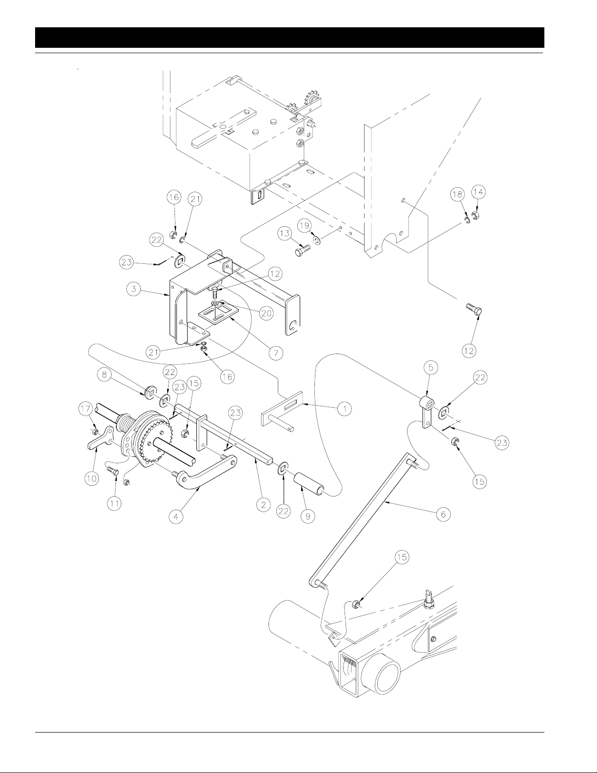
Section 3 7’ EWNT Clutch Linkage Update Assembly
13804
5
7’ & 10’ End Wheel No-Till Clutch Linkage 152-156M 5/3/96
Great Plains Mfg., Inc.
Page 11

Section 3 7’ EWNT Clutch Linkage Update Assembly
Ref. Part No. Part Description
1. 123-832H Slotted Idler Arm 1/2" x 2 13/16"
2. 152-143H 7' Clutch Rod
3. 152-144H 7' Clutch Rod Support
4. 152-145H 7' Clutch Link Pull Arm
5. 152-147H 7' & 10' Clutch Rod Push Arm
6. 152-149H 7' & 10' Clutch Arm Seed Only
152-148H 7' & 10' Clutch Arm Fertilizer, NG
7. 152-305D 7' & 10' Clutch Tab Adjust
8. 152-306D Clutch Rod Pivot Bushing
9. 152-308D Clutch Rod Spacer
10. 152-262D Clutch Engage Arm
11. 802-017C Bolt, Hex Head 3/8"-16 x 1" Long
12. 802-079C Bolt, Hex Head 3/8"-16 x 1 1/4" Long
13. 802-159C Bolt, Hex Head 5/16"-18 x 1" Long
14. 803-008C Nut, Hex 5/16"-18
15. 803-013C Nut, Lock 3/8"-16
16. 803-014C Nut, Hex 3/8"-16
17. 803-078C Nut, Lock 3/8"-16 Nylon Insert
18. 804-009C Washer, Lock Spring 5/16"
19. 804-010C Washer, Flat 5/16" USS
20. 804-012C Washer, Flat 3/8" SAE
21. 804-013C Washer, Lock Spring 3/8"
22. 804-031C Washer, Retaining
23. 805-019C Pin, Cotter 5/32" x 1" Long
5/3/96
Great Plains Mfg., Inc.
7’ & 10’ End Wheel No-Till Clutch Linkage 152-156M
6
Page 12
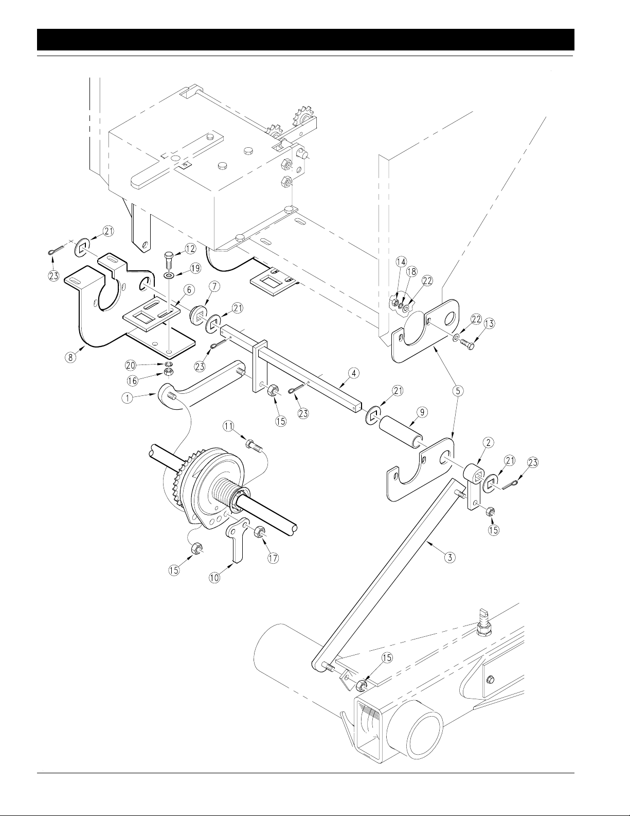
Section 3 10’ EWNT Clutch Linkage Update Assembly
13807
7
7’ & 10’ End Wheel No-Till Clutch Linkage 152-156M 5/3/96
Great Plains Mfg., Inc.
Page 13

Section 3 10’ EWNT Clutch Linkage Update Assembly
Ref. Part No. Part Description
1. 152-146H 10' Clutch Link Pull Arm
2. 152-147H 7' & 10' Clutch Rod Push Arm
3. 152-149H 7' & 10' Clutch Arm Seed Only
152-148H 7' & 10' Clutch Arm Fertilizer & Native Grass
4. 152-150H 10' Clutch Rod
5. 152-297D 10' Clutch Rod Support Mount
6. 152-305D 7' & 10' Clutch Tab Adjust
7. 152-306D Clutch Rod Pivot Bushing
8. 152-307D 10' Clutch Tab Adj Mount
9. 152-308D Clutch Rod Spacer
10. 152-262D Clutch Engage Arm
11. 802-017C Bolt, Hex Head 3/8"-16 x 1" Long
12. 802-079C Bolt, Hex Head 3/8"-16 x 1 1/4" Long
13. 802-159C Bolt, Hex Head 5/16"-18 x 1" Long
14. 803-008C Nut, Hex 5/16"-18
15. 803-013C Nut,Lock 3/8"-16
16. 803-014C Nut, Hex 3/8"-16
17. 803-078C Nut, Lock 3/8"-16 Nylon Insert
18. 804-009C Washer, Lock Spring 5/16"
19. 804-012C Washer, Flat 3/8" SAE
20. 804-013C Washer, Lock Spring 3/8"
21. 804-031C Washer, Retaining
22. 804-036C Washer, Flat 5/16" SAE
23. 805-019C Pin, Cotter 5/32" x 1" Long
5/3/96
Great Plains Mfg., Inc.
7’ & 10’ End Wheel No-Till Clutch Linkage 152-156M
8
Page 14

Great Plains Manufacturing, Inc.
Corporate Offices: PO. Box 218
Assaria, Kansas 67416 USA
Phone (913) 667-4755
FAX (913) 667-2055
 Loading...