

Page 1
Great Plains Mfg., Inc.
Update Instructions
EWD13 and EWF13
Sprocket Box Update
Used with:
13-Foot, End-Wheel Drills
•
When you see this symbol, the subsequent instructions and
warnings are serious - follow without exception. Your life and
!
the lives of others depend on it!
General Information
These instructions explain how to install and adjust the sprocketbox update. The sprocket box replaces the original gearbox on
Great Plains end-wheel drills. This modification improves the
performance and reliability of the original equipment.
Assembly Instructions
Disassembling the Gearbox
1. Remove end-wheel-output and gearbox-output chains.
2. If your drill has 7-, 8- or 10-inch row spacings, you must install a new opener-lift arm and remove the existing arm. If
your drill has 6- or 7.5-inch row spacings, proceed to step
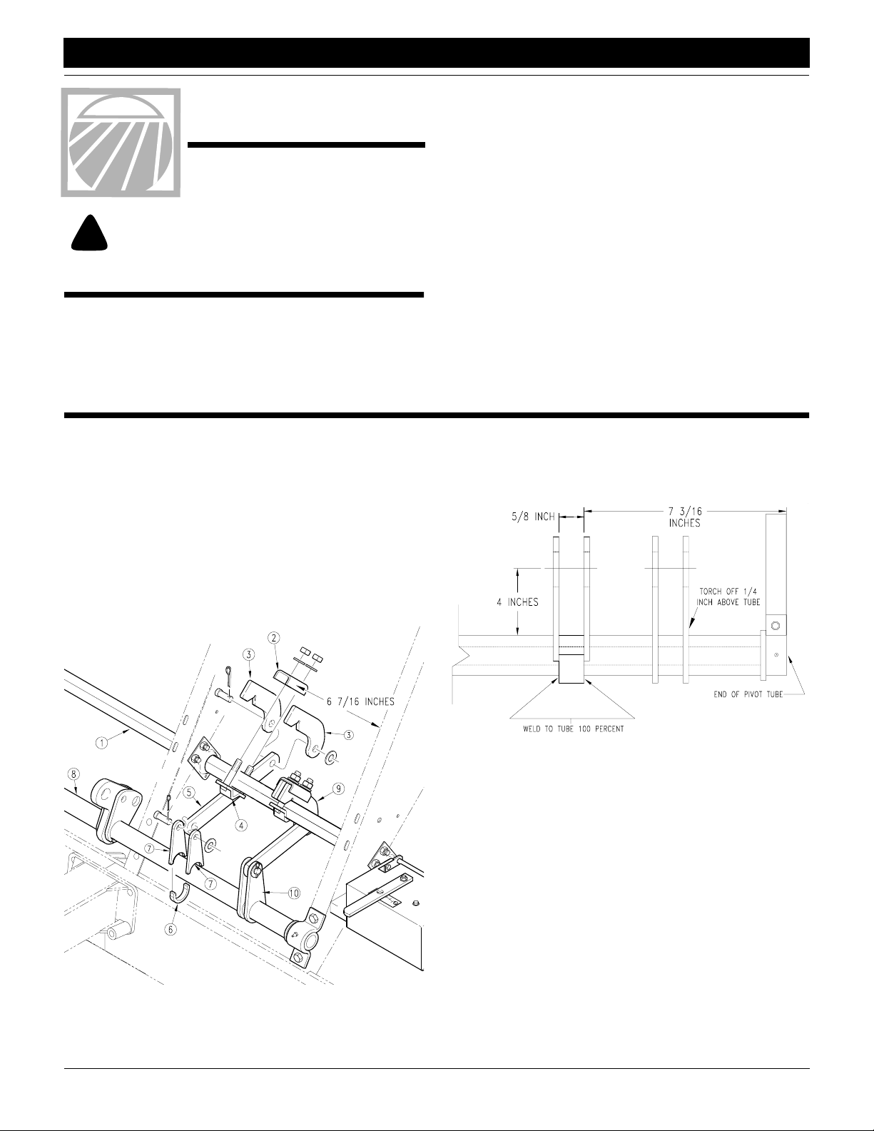
To reposition the opener-lift arm, refer to Figure 1-1.
a. Assemble the clamp on the square opener shaft (1).
Place the channel bracket (2) over the link arms (3). Position the clamp 6 7/16 inches from the frame plate. Secure to shaft with the mounting strap (4), 5/8-inch
washers and bolts.
b. Using a 3/4-inch clevis and cotter pin, pin the link arm
(5) to the newly installed clamp.
These instructions apply to
152-207A 13-Foot EW Sprocket Box Update Kit
Manual Update
Pages 4 and 5 of these instructions cover how to adjust the seeding rate with the new sprocket box. These instructions replace
the "Clutch Shaft and Miter Gear Alignment" and "Seed Calibration" sections in the operator’s manual originally provided with
your drill. As reference, save pages 3 and 4 of these instructions
with your operator’s manual. A copy of the updated parts manual
is available through your Great Plains dealer.
Refer to the drill operator’s manual for detailed information on
safely operating, adjusting, troubleshooting and maintaining the
drill. Refer to the drill parts manual for part identification.
• 13-Foot End Wheel Drill Operator’s Manual . . . . . . . . . . . . . . . . . . . 175-083M
• 13-Foot End Wheel Drill Parts Manual . . . . . . . . . . . . . . . . . . . . . . . 175-083P
Before You Start
Page 6 is a detailed listing of parts included in the sprocket-boxupdate kit. Use this list to inventory parts received.
c. Weld the mount collar (6) and double ears (7) on the
pivot tube (8) so you can pin the link arm to the ears.
Use the link arm as a guide to properly position the collar and ears on the tube. Refer to Figure 1-2 for general
dimensions.
3.
Figure 1-1
Opener Lift Arm
© Copyright 1998 Printed 2/24/98
16597
16598
Figure 1-2
Weld and Torch Diagram
d. Pin the link arm to the double ears using the 3/4-inch
clevis and cotter pins.
e. Remove existing opener-lift arm (9) by torching off the
double ears (10). Cut the ears 1/4 inch above the pivot
tube. Disassemble the existing opener-shaft clamp.
Discard all disassembled parts.
f. Spray paint the pivot tube with the paint provided. Thor-
oughly cover the welds and any paint damage.
152-208M
1
Page 2
Assembly Instructions
Great Plains Mfg., Inc.
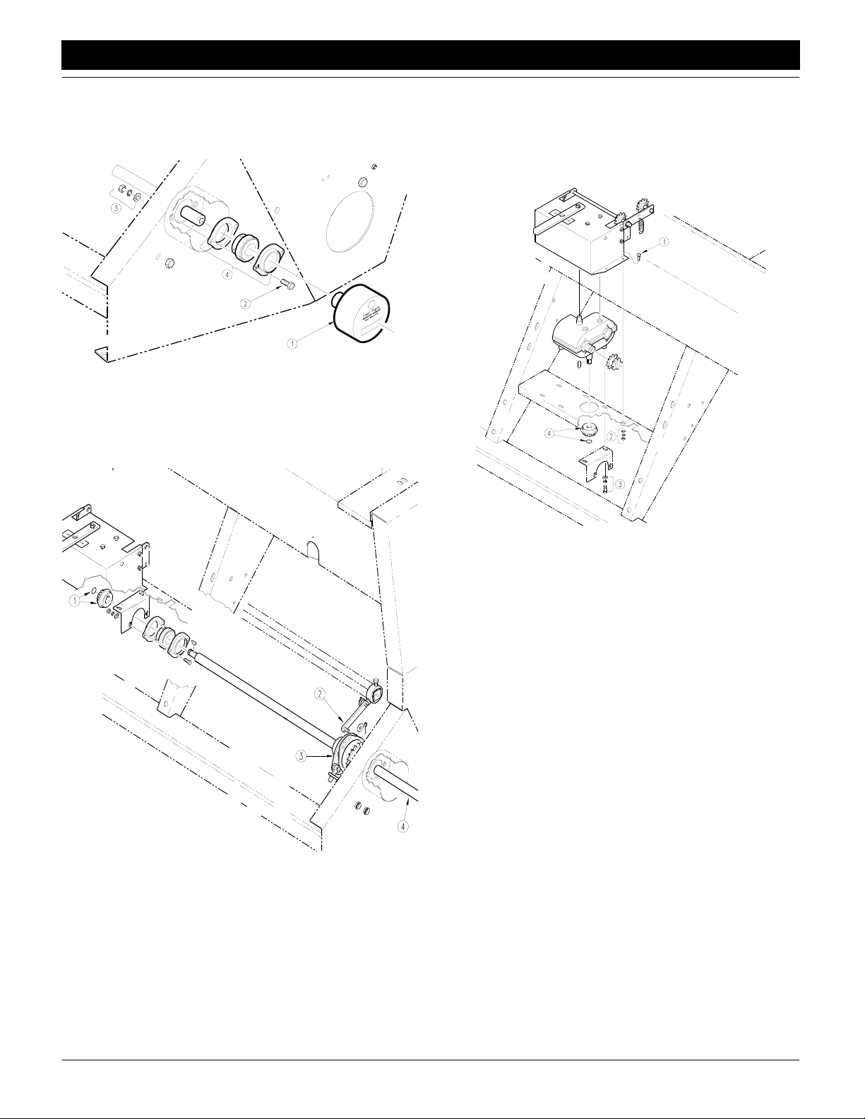
Refer to Figure 1-3.
3. Disassemble acremeter. Unscrew acremeter (1) off shaft.
Remove the 5/16-inch bolts (2), washers and nuts (3). Re
move bearings (4). Save acremeter, bolts, washers, nuts
and bearings for later reinstallation.
16507
Figure 1-3
Acremeter Disassembly
Refer to Figure 1-4.
4. Remove jackshaft. Remove snap ring and miter gear (1)
from gearbox end of shaft. Disconnect clutch link arm (2)
from clutch (3). Slide shaft (4) out of bearings, clutch and
side wall. Save clutch for later reinstallation.
Refer to Figure 1-5.
5. Remove gearbox. Remove 1/4-inch bolts (1), washers and
-
nuts (2) that hold the gearbox cover on mounting plate. Re
move the bolts and washers (3) that hold the bearing bracket
to the mounting plate and gearbox transmission. Remove
the snap ring and miter gear (4). Lift the gearbox off the
mounting plate.
-
16508
16509
Figure 1-5
Gearbox Removal
Figure 1-4
Jackshaft Removal
EWD13 and EWF13 Sprocket Box Update 152-208M 5/2/06
2
Page 3

Great Plains Mfg., Inc.
Assembly Instructions
Installing the Sprocket Box
Refer to Figure 1-6.
1. Drill two 13/32-inch holes for idler bracket. First, bolt the idler
bracket (1) to the mounting plate (2) using a 1/4-inch bolt (3),
washer, lock washer and nut (4) at the location shown. The
idler bracket will wrap around the right-hand side of the
frame plate (5). Use the two bolt holes (6) in the bracket as
a guide for where to drill. When finished drilling, unbolt the
idler bracket from the mounting plate.
2. Assemble bearings (7) on the idler bracket using 5/16-inch
bolts (8), washers, lock washers and nuts (9).
3. Assemble idlers (10) on idler bracket. Bolt the idlers to the
bracket in the order shown (sprocket, 5/8-inch nut, flat wash
er, bracket, flat washer, lock washer, nut).
4. Mount the idler bracket on the mounting plate and through
the frame-plate holes drilled in step
et to the frame plate using 3/8-inch bolts (11), washers, lock
washers and nuts (12).
5. Install sprocket box. Bolt the box (13) to the mounting plate
through four holes using 5/16-inch bolts (14), washers, lock
washers and nuts (15).
6. Install new jackshaft. Slide jackshaft (16) through side wall
and clutch, under mounting plate and through idler bracket.
Install the 12-tooth sprocket (17) on the end of the shaft and
secure with the 1/4-inch key (18).
7. Route 119-pitch chain (19) over sprocket-box input and
idlers as shown. Route 83-pitch chain (20) over gearbox out
-
put, idler and seed-cup-shaft input as shown.
8. Reconnect clutch-link arm and reinstall gauge-wheel-tojackshaft chain. Reassemble acremeter.
1. Mount the idler brack-
-
5/2/06
Figure 1-6
Idler Plate and Gearbox Installation
16514
EWD13 and EWF13 Sprocket Box Update 152-208M
3
Page 4

Seed Calibration
Great Plains Mfg., Inc.
Seeding Adjustment
Calibrating the seeding rate requires four steps: arranging the
drive sprockets, setting the seed-rate handle, positioning the
seed-cup doors, and checking the seeding rate.
Refer to the seed-rate charts. These charts list the proper
sprocket sizes and seed-rate-handle settings for various seeds
and seeding rates.
The seed-rate charts are based on cleaned, untreated seed of
average size and test weight. The charts are based on 9.5 x 20
rib implement tires. Many factors will affect seeding rates including foreign material, seed treatment, seed size, field conditions,
tire pressure and test weight. You likely will need to make minor
adjustments. Set and check the seeding rate using the procedures below, then re-adjust the rate as necessary.
NOTE: A pea-drive adaptor kit is available for the 13-foot endwheel drill. Different seed-rate charts are included in the peadrive kit.
Change Drive Sprockets
The seed-rate charts in your operator’s manual and in your drill
box list drive types as 1, 1A, 2 or 2A. Refer to the seed-rate
charts for the correct drive type.
Figure 1-7 shows sprocket sizes for each drive type.
Type 2
Type 2A
To change the drive types:
1. Refer to Figure 1-8. Loosen the nut (1) holding the idler arm
(2) and turn arm so chain is slack. Remove chain from
sprockets.
2
1
16473
Figure 1-8
Loosen Idler Spacer
2. Refer to Figure 1-9. Rearrange sprocket (1) and plastic
spacers (2) on front shaft so the proper front and rear
sprockets are aligned according to drive type.
3. Slide idlers on idler arms so they are aligned with correct
sprockets. Reinstall chain.
4. Turn idler arm as indicated by drive type to remove slack
from chain. Retighten nut that holds idler arm.
Type 1
Figure 1-7
Sprocket-Box Drive Types
Type 1A
Drive Types
Type 2 is Slowest
Type 2A is Two Times Faster than Type 2
Type 1 is Three Times Faster Than Type 2
Type 1A is Five Times Faster than Type 2
1
Figure 1-9
Rearrange Sprockets on Front Shaft
2
16475
EWD13 and EWF13 Sprocket Box Update 152-208M 5/2/06
4
Page 5

Great Plains Mfg., Inc.
Seed Calibration
Set Seed-Rate Handle
The position the handle shown in Figure 1-10 to the setting indicated on the chart. To adjust the handle, loosen the wing nut under the handle and slide until the indicator lines up with the
correct setting.
12927
Figure 1-10
Seed-Rate Handle
Position Seed-Cup Doors
For wheat and other small seeds, move the seed-cup-door handles to the highest position. For soybeans and other large seeds,
lower the handles to the second position. If excessive seed
cracking occurs, lower the handles to the third position. Move the
handles to the fourth, wide-open position for seed-cup clean out.
Make sure all handles are in the same position before drilling.
Check Seeding Rate
1. Hydraulically lower the drill to planting position to activate
clutch.
2. Check that your gauge-wheel tires are 9.5 x 20 rib implement and properly inflated. Refer to Tire Inflation Chart in
your operator’s manual.
3. Jack the drive (left) end wheel off the ground. Rotate the
wheel to see that the drive system is working properly and
seed cups are free from foreign material.
4. Record the weight of an empty container large enough to
hold the seed metered for one acre.
5. Place several pounds of seed over three seed cups on an
outside end of the drill box. Pull the seed tubes off of these
three openers.
6. Turn the drive wheel several times to fill the seed cups. Turn
wheel until seed drops to the ground from each seed cup.
7. Place a container under the three tubes to gather metered
seed.
8. Rotate the drive wheel until one acre has been tallied on the
acremeter. This will be 348 rotations on a 13-foot drill. Check
that the three seed cups have plenty of seed coming into
them.
9. Weigh the metered seed. Subtract the initial weight of the
container. Divide by three. Multiply by the number of open
ers on your drill to determine total pounds-per-acre seeded.
If this figure is different than desired, reset sprockets accord
ingly.
NOTE: You may want to repeat the calibration procedure if your
results vary greatly from the seed-rate chart.
10. When drilling, check the rate by noting acres drilled, amount
of seed added to drill and seed level in drill box. If you are
seeding more or less than desired, adjust the rate slightly to
compensate for field conditions.
-
-
5/2/06
Figure 1-11
Seed-Cup-Door Handle
13867
EWD13 and EWF13 Sprocket Box Update 152-208M
5
Page 6

Listing of Parts
152-207A 13-Foot End-Wheel Sprocket Box Update Kit
Your Kit Includes:
Qty. Part No. Part Description
1 123-004D KEY 1/4 X 1
1 136-055D CHAIN RL #40 119 PITCHES
1 152-196K 13' SPROCKET BOX ASSEMBLY
1 152-208M MANUAL 13 EW SPKT BOX UPDT
1 152-402D 13' IDLER SUPPORT PLATE
1 152-405D 13' EW LOWER JACK SHAFT
2 152-409D 13' LIFT LUG UPDATE
1 152-410D 13' LIFT LUG SPACER UPDATE
1 175-041H MOUNTING STRAP WELDMENT
1 175-053D OPENER LIFT LINK
1 175-054D PIVOT ARM CHANNEL
1 802-004C HHCS 1/4-20X3/4 GR5
2 802-017C HHCS 3/8-16X1 GR5
3 802-055C HHCS 5/8-11X2 GR5
4 802-159C HHCS 5/16-18X1 GR5
2 802-282C RHSNB 5/16-18X1 GR5
1 803-006C NUT HEX 1/4-20 PLT
6 803-008C NUT HEX 5/16-18 PLT
2 803-014C NUT HEX 3/8-16 PLT
2 803-021C NUT HEX 5/8-11 PLT
6 803-023C NUT HEX JAM 5/8-11 PLT
1 804-006C WASHER LOCK SPRING 1/4 PLT
6 804-009C WASHER LOCK SPRING 5/16 PLT
6 804-010C WASHER FLAT 5/16 USS PLT
2 804-011C WASHER FLAT 3/8 USS PLT
2 804-013C WASHER LOCK SPRING 3/8 PLT
6 804-021C WASHER FLAT 5/8 SAE PLT
5 804-022C WASHER LOCK SPRING 5/8 PLT
2 804-025C WASHER FLAT 3/4 SAE PLT
1 804-075C WASHER FLAT 1/4 USS PLT
2 805-045C PIN COTTER 5/32 X 1 1/4 LG
2 805-083C PIN CLEVIS 3/4 X 1 1/2
1 808-024C SPKT 40B12 X 1 BORE
3 808-046C SPKT 40A17 IDLER
1 809-096C #40 CONNECTOR LINK-PLATED
1 809-135C CHAIN RL #40 X 111 PITCH W/CON
1 818-811C DECAL DRILLS SPROCKET CHANGE
1 821-002C PAINT GP BLACK SPRAY CAN
2 822-032C FLANGETTE 52 MST
1 822-060C BEARING 1 BORE W/LOCK COLLAR
Great Plains Mfg., Inc.
EWD13 and EWF13 Sprocket Box Update 152-208M 5/2/06
6
 Loading...