

Page 1
Operator’s Manual
13-Foot End Wheel Drill
Model Serial No.
EWD13 4109R+
Manufacturing, Inc.
P.O. Box 5060 ● Salina, Kansas 67402-5060
Read the operator’s manual entirely. When you see this symbol, the subsequent in-
!
structions and warnings are serious -follow without exception. Your life andthelives of
others depend on it!
EWD13
© Copyright 1997 Printed
9/5/97
16500
Cover illustration may show optional equipment not supplied with standard unit.
175-083M-A
Page 2

4/3/95
DEALER PREPARATION CHECK LIST
PREDELIVERY
Before delivering machine the following check list should be completed. Use this Owner’s Manual as a guide.
1. ❑ Assembly completed.
2. ❑ Fluids added & checked.
3. ❑ All grease fittings lubricated. Refer to "Maintenance & Lubrication" section.
4. ❑ Check & tighten all hardware. Refer to "Nut & Bolt Torquing Chart".
5. ❑ All decals are in place & readable. See "Decal Placement" section.
6. ❑ All safety shields or guards are in place.
7. ❑ Overall conditions good {i.e. paint, welds}.
This check list is to remain in Owner’s Manual.
0-1
It is the responsibility of the dealer to complete the procedures listed above BEFORE delivery of this
machine to the customer.
DELIVERY
Review this Owner’s Manual with the customer. Explain the following & check off as completed.
1. ❑ Safety procedures for operation & service.
2. ❑ Basic operating & adjustments.
3. ❑ Daily & periodic maintenance & lubrication. Refer to "Maintenance & Lubrication" section.
4. ❑ Correct lubricants & usage.
5. ❑ Great Plains parts & service.
6. ❑ Record serial number. See "Introduction" on next page.
7. ❑ Remind customer that alldecals should remain in place & readable. See "Decal Placement" section& con-
tact dealership for replacements when needed.
8. ❑ Remind customer that ALL safety shields & guards are not to be removed.
9. ❑ Give customer this Owner’s Manual & encourage them to read it.
175-083M-A
Effective 4/8/99
175-083M-A
Page 3

0-2
Your Great Plains End Wheel Drill is designed to give you many years of dependable service. This
manual has been prepared to instruct you in the safe and efficient operation of this machine. Read
and study it thoroughly. Follow all instructions and service procedures carefully.
The parts on your End Wheel Drill have been specially designed and should only be replaced with
genuine Great Plains parts. Therefore; should your drill require replacements parts, purchase them
from your Great Plains Dealer.
Spacehas beenprovided below for you torecord yourmodel numberand serialnumber of your drill.
Be sure to bring this information with you to your dealer when ordering parts or attachments for your
drill.
The following signal symbol and words should be clearly understood! Whenseen in this manual or
on your equipment, this symbol and words will alert you to the seriousness of a situation. They
should not be ignored or taken lightly.
INTRODUCTION
4/8/99
!
The SAFETY ALERT SYMBOL indicates that there is a potential hazard to personal safety
involved and extra safety precautions must be taken. When you see this symbol, be alert and carefully read the message that follows it. In addition to design and configuration of equipment; hazard
control and accident prevention are dependent upon the awareness, concern, prudence and proper
training of personnel involved in the operation, transport, maintenance and storage of equipment.
DANGER:Indicates an imminently hazardous situation which, if not avoided, will result in death
or serious injury. This signal word is limited to the most extreme situations.
WARNING: Indicates a potentially hazardous situation which, if not avoided, could result in
death or serious injury.
CAUTION: Indicatesa potentially hazardous situation which, if not avoided, may result in minor
or moderate injury. It may also be used to alert against unsafe practices.
Thank you for buying a Great Plains End Wheel Drill.
SERIAL NUMBER ___________________
MODEL NUMBER ___________________
DATE PURCHASED _________________
175-083M-A
Page 4

4/3/95
TABLE OF CONTENTS
Delivery Check Lists---------------------------------------------------------------------0-1
Introduction --------------------------------------------------------------------------------0-2
Table of Contents ------------------------------------------------------------------------0-3
Safety Rules ------------------------------------------------------------------------------1-1
Safety Decals -----------------------------------------------------------------------------1-2
Safety Decal Placement ----------------------------------------------------------------1-3
Nut & Bolt Torquing Chart -------------------------------------------------------------1-4
Tire Inflation Chart -----------------------------------------------------------------------1-4
Tongue & Pull Bar Assembly ----------------------------------------------------------2-1
Step Assembly ----------------------------------------------------------------------------2-2
Tractor Requirements--------------------------------------------------------------------2-3
Tractor Draw Bar Hook-Up-------------------------------------------------------------2-3
Tractor Hydraulic Hook-Up-------------------------------------------------------------2-3
Bleeding Opener Lift Hydraulics------------------------------------------------------2-4
Transport Lock-----------------------------------------------------------------------------3-1
Hydraulic Depth Control ----------------------------------------------------------------3-1
Transporting--------------------------------------------------------------------------------3-2
0-3
Drive Train
Clutch -------------------------------------------------------------------------------------4-1
Chain Drive ------------------------------------------------------------------------------4-1
Seed Calibration -------------------------------------------------------------------------5-1
Changing Drive Sprockets-----------------------------------------------------------5-1
Setting Seed-Rate Handle-----------------------------------------------------------5-2
Positioning Seed-Cup Doors--------------------------------------------------------5-2
Checking Seeding Rate --------------------------------------------------------------5-2
Seed Rate Charts ------------------------------------------------------------------------5-3
Granular Fertilizer Operating Instructions------------------------------------------6-1
Fertilizer Application Chart-------------------------------------------------------------6-1
Fertilizer Drive-----------------------------------------------------------------------------6-2
Press Wheel Depth Adjustments-----------------------------------------------------7-1
Press Wheel Angle Adjustment {2" x 13" Double "V"} --------------------------7-1
Individual Opener Spring Pressure Setting----------------------------------------7-2
Seeding In Tractor Tire Tracks---------------------------------------------------------7-2
Drill Preparation---------------------------------------------------------------------------8-1
Operating Check List -------------------------------------------------------------------8-1
Maintenance & Lubrication ------------------------------------------------------------9-1
Storage -------------------------------------------------------------------------------------9-1
Trouble Shooting ----------------------------------------------------------------------- 10-1
Specifications --------------------------------------------------------------------------- 10-3
175-083M-A
Page 5

0-4
4/8/99
175-083M-A
Page 6

4/3/95
0-5
175-083M-A
Page 7

4/3/95
SAFETY RULES
! !
The safe operation of machinery is a big concern to farmers and manufacturers. Wehave designed
our End Wheel Drill with many built-in safety features. However, no one should operate this drill
before carefully reading this Owner’s Manual.
1. NEVER permit anyone to ride on or walk beside the drill when moving.
2. NEVER permit anyone to ride on tractor when the drill is being moved.
3. NEVER allow anyone to be near the drill when performing operating functions with the drill or
tractor.
4. DO NOT allow anyone to operate the Drill who has not been properly trained in its safe operation.
5. ALWAYS fasten the drill hitch securely to the tractor drawbar with a safety lock type pin & fasten safety chain securely to tractor.
6. NEVER load the drill without being hooked up to a tractor
7. NEVER exceed 20 MPH when transporting.
8. Extra care should be taken when transporting with seed in the boxes.
1-1
9. Reduce speed of the tractor when transporting over uneven or rough terrain. Avoid all chuck
holes and washboard areas in roads.
10. Reduce speed of the tractor when transporting over hills or steep slopes.
11. When in transport, use accessory lights and devices for adequate warning to operators of other
vehicles and use safety hitch chain. Comply with all Federal, State and Local laws when traveling on public roads.
12. Use "Slow Moving Vehicle" emblem for warning vehicles approaching from the rear.
13. When transporting, remember the drill is wider than your tractor and extreme care must be taken to allow for safe clearance.
14. NEVER back up when openers are in the ground.
15. ALWAYS set the drill in field position BEFORE lubrication, making adjustments, or servicing.
16. DO NOT lubricate, adjust or repair the drill while it is in operation.
17. DO NOT permit smoking, sparks, or an open flame where combustible lubricants or liquids are
being used.
18. When using treated seed, avoid direct contact with the seed.
19. When using compressed air to clean the drill, wear safety glasses.
20. NEVER unhook drill from tractor when negative tongue weight is present.
!
CAUTION! Escaping fluid under pressure can have sufficient force to penetrate the
skin. Check all hydraulic lines and hoses BEFORE applying pressure. Fluid escaping from
a very small hole can be almost invisible. Use paper or cardboard, NOT BODY PARTS, to
check for suspected leaks. If injured, seek medical assistance from a doctor that is familiar
with this type of injury. Foreign fluids in the tissue must be surgically removed within a few
hours or gangrene will result.
175-083M-A
Page 8
1-2
SAFETY DECALS
! !
Slow Moving Vehicle
Emblem
818-055C
4/8/99
!
WARNING
20 MPH MAX.
TRANSPORT SPEED
EXCEEDING 20 MPH MAY RESULT IN LOSS OF VEHICLE
CONTROL AND / OR IMPLEMENT DAMAGE
818-188C
--IMPORTANT--
* Your End Wheel Drill comes equipped with all safety decals in place.
* Always keep safety decals clean and legible.
* Replace all damaged or missing safety decals. To order new safety decals go to your Great
Plains Dealer and reference part numbers as shown on page 1-3.
Reflector - Red Reflector - Amber
818-229C818-230C
* To install new safety decals:
A) Clean the area the decal is to be placed. (Refer to page 1-3.)
B) Peel backing from decal and press firmly onto clean surface.
175-083M-A
Page 9
4/3/95
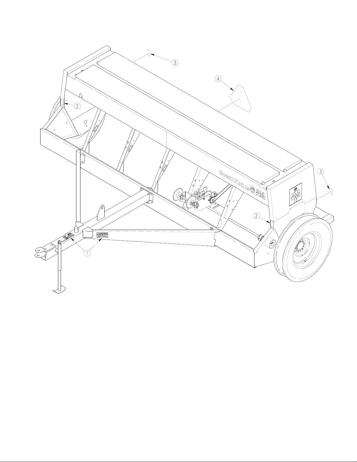
SAFETY DECAL PLACEMENT {175-087A}
Includes ALL SAFETY Decals As Shown Below.
1-3
Ref. Part No. Description
1. 818-188C Warning Transport Speed
2. 818-229C Amber Reflectors
3. 818-230C Red Reflectors
4. 818-055C Slow Moving Vehicle
16503
175-083M-A
Page 10

1-4
NUT & BOLT TORQUING CHART
This chart is based on torque requirements in foot pounds for grade 5 bolts.
BOLT MINIMUM MAXIMUM BOLT MINIMUM MAXIMUM
DIAMETER TORQUE TORQUE DIAMETER TORQUE TORQUE
1/4” 9 11 3/4” 270 324
5/16” 17 20 7/8” 400 480
3/8” 35 42 1" 580 696
7/16” 54 64 1 1/8” 800 880
1/2” 80 96 1 1/4” 1120 1240
9/16” 110 132 1 3/8” 1460 1680
5/8” 150 180 1 1/2” 1940 2200
NOTE: Torque requirements listed above do not apply to self-locking nuts. For self-locking nuts increase the torque
requirements listed above by 15%.
4/8/99
TIRE INFLATION CHART
TIRE SIZE INFLATION PSI
5.90 x 15" 4 Ply Rib Implement 32
7.50 x 20" 4 Ply Rib Implement 28
9.0 x 22.5 10 Ply Highway Service 70 70
9.0 x 24" 8 Ply Rib Implement 40
9.5L x 15" 6 Ply Rib Implement 32
9.5L x 15" 8 Ply Rib Implement 44
9.5L x 15" 12 Ply Rib Implement 60
11L x 15" 6 Ply Rib Implement 28
11L x 15" 12 Ply Rib Implement 52
12.5L x 15" 8 Ply Rib Implement 36
12.5L x 15" 10 Ply Rib Implement 44
16.5L x 16.1" 10 Ply Rib Implement 36
41 x 15" x 18 22 Ply Rib Implement 44
175-083M-A
Page 11

4/3/95
1-5
175-083M-A
Page 12

1-6
4/8/99
175-083M-A
Page 13

4/8/99
END WHEEL TONGUE & PULL BARS ASSEMBLY INSTRUCTIONS
For the following assembly instructions, refer to Fig. 1 below.
2-1
1. Remove the 5/8" x 3 1/2" x 5" long u-bolts (#17), 5/8"
lockwashers (#19), and 5/8" nuts(#18) that hold theopener channel to the drill frame for shipping. Remove 1/2"nut
(#8) and 1/2" lockwasher (#7) from the front of the opener
channel leaving the 1/2" x 3 1/2" x 4 3/4" long u-bolt (#6)
in place.
2. Assemble the rear of right and left pull bars (#1), {left
hand shown} to the drill. First use 1/2" x 1" long carriage
bolt(#2) and whiz nut (#3) to boltthe bottom leg of pull bar
to the bottom leg of the opener channel.
3. Lift pull bar (#1) up and bolt top leg using 1/2" x 1 1/4"
long whiz bolt (#4) and whiz nut (#5).
4. Attach insideleg of pull bar with 1/2" x3 1/2" x 4 3/4" long
u-bolt (#6), 1/2" lock washers (#7), and 1/2" hex nut (#8).
5. Attach outside leg of pull bar with 1/2" x 1 1/2" whiz
bolts (#9), and whiz nuts (#10).
NOTE: DO NOT tighten hardware until final assembly.
6. Lay the tongue (#11) between the pull bars (#1) and
bolt to the drill with 5/8" x 3 17/32" x uneven leg u-bolts
(#12), 5/8" lock washers (#13), and 5/8" hex nuts (#14).
7. Assemble the front end of pull bars to the tongue
(#11) with 1/2" x 1 1/4" long whiz bolts (#15), and whiz
nuts (#16).
8. Tighten ALL mounting hardware when assembly is
completed.
10251
Tongue & Pull Bar Assembly Drawing
Fig. 1
175-083M-A
Page 14

2-2
END WHEEL STEP ASSEMBLY INSTRUCTIONS
For the following assembly instructions, refer to Fig. 2 below.
4/3/95
1. Start the bolts on each end of the step weldment (#1)
to the drill (#2) using 3/4" x 2" long bolts (#3), 3/4" lock
washers (#4), and 3/4" SAE flat washers (#5).
NOTE: DO NOT tighten hardware until final assembly.
2. Bolt the step hanger weldment (#6) to the center
mount(#7)onthedrillbox(#2)using1/2"x11/4"longhex
bolts(#8),1/2"lockwashers (#9), and 1/2"hexnuts(#10).
Bolt the lower part of thestep hanger to the front leg of the
step using the same 1/2" hardware.
3. Tighten ALL hardware when assembly is complete.
4. Mount the Slow Moving Decal (#11) to the step
hanger using 1/4" x 5/8" long round head screws (#12),
1/4" lock washers (#13), and 1/4" hex nuts (#14).
10239
175-083M-A
Step Assembly Instructions Drawing
Fig. 2
Page 15

4/8/99
TRACTOR REQUIREMENTS
2-3
A minimum 65 H.P. tractor is required to operate your 13’
End Wheel Drill in most field conditions.
1. One remote outlet is required to operate the drill.
TRACTOR DRAW BAR HOOKUP
When hitching the drill to the tractor drawbar, it is important to level the drill by adjusting the tongue jack so that
the drill box is parallel with the ground.
The hitch clevis straps can now be adjusted to match the
tractor drawbar height, Fig. 3.
Your drill comes equipped with a hitch safety chain. The
safety chain should be securely attached to the drill hitch
and the tractor drawbar whenever towing or planting.
Pin the drill hitch to tractor drawbar and lower the tongue
using the screw jack. Unpin the tongue jack and move it
to its horizontal transport position on top of tongue.
NOTE: Make sure the hitch is securely bolted to the drill
tongue.
ALWAYS use a pin that contains a safety locking device
to prevent it from falling out.
ALWAYS Attach safety chain from the drill hitch to the
tractorand lock the hook securely onthe chain. Adjust the
chainlength to allow just enough slackto permit turning of
the drill and tractor.
2. Two remote outlets are required if your drill is
equipped with markers.
11189
Clevis Hitch
Fig. 3
HYDRAULIC HOOK-UP
Attach the female swivel end of the hydraulic hoses to the
fittings on the cylinder.
You are now ready to hook-up your hydraulic hoses. Apply pipe sealant to the male pipe end of the hydraulic fitting and screw the two hydraulic fittings into your cylinder
ports. Then insert hydraulic hoses throughthe spring type
hose loop on the tongue and attach hydraulic male coupler tip to hoses. Plug the male coupler into tractor outlets
as instructed in your tractor operators manual.
When using sealant on pipe threads the friction between
!
CAUTION! Escaping fluid under pressure can have sufficient force to penetrate the
the threads is reduced, therefore be certain not to over
tighten causing damage to the cylinder port or fitting.
NOTE: JIC fittings DO NOT require high torque. JIC
and O-Ring fitting do not require sealant. ALWAYS use
liquid pipe sealant when adding or replacing pipe thread
fittings. To avoid possible danger of cracking hydraulic
fittings from over tightening, DO NOT use plastic sealant tape.
skin. Check all hydraulic lines and hoses BEFORE applying pressure. Fluid escaping from
a very small hole can be almost invisible. Use paper or cardboard, NOT BODY PARTS, to
check for suspected leaks. If injured, seek medical assistance from a doctor that is familiar
with this type of injury. Foreign fluids in the tissue must be surgically removed within a few
hours or gangrene will result.
175-083M-A
Page 16

2-4
BLEEDING OPENER LIFT HYDRAULICS
4/3/95
This End Wheel Drill requires the use of a 3 1/2" bore x 8"
stroke cylinder with a 20 1/4" {pin to pin} retracted length.
NOTE: Check the hydraulic fluid level in the tractor reservoirandfilltotheproperlevel. If the bleeding isperformed
with a low tractor reservoir supply, there is a chance of
drawing air into the system. The system capacity is approximately 1/2 gallon and requires 1 pair of remote outlets.
1. With the transport lock in thetransportposition,referto
"Operating Transport Lock" on page 3-1. Loosen the
connection between the hose end and the cylinder base
end fitting.
2. With the tractor at idle, slowly retract the lift cylinder.
When the air is expelled and oil starts flowing out, tighten the base end hose connection.
3. Repeat this procedure with the rod end hose connection while extending the cylinder.
4. Recheck the tractor reservoir level and add cleanfluid as necessary.
5. It is advisable to extend and retract the lift cylinder
several times. The majority of air should now be expelled from the system. Any remaining airwill gradually
be pushed to the tractor during day to day operations.
175-083M-A
Page 17

4/3/95
TRANSPORT LOCK
3-1
To prepare your drill for field operation, you first must fully
extendthecylinder,removethetransportlockpinfromthe
lower hole in the rod end cylinder lug Fig. 4 and replace in
the upper hole Fig. 5.
11183
Lock Pin In Transport Position
Fig. 4
When transporting long distances, or transporting without
a cylinder, the transport lock pin should be placed in the
lock position as shown in Fig. 4.
11755
Lock Pin In Field Position
Fig. 5
NOTE: If your drill is equipped with markers the marker
bodymust be pinned up for transport. SeeMarker Manual
located in Optional Equipment Section.
HYDRAULIC DEPTH CONTROL
The optional cylinder package purchased with your drill
contains a hydraulic cylinder with depth control stop, Fig.
6. This cylinder allows for a variable adjustment from zero
to maximum stroke which controls the down pressure applied to your disk openers. In order to adjust the stroke of
the cylinder, retract cylinder until the openers are set at
the desired down pressure required. Next, loosen the bolt
on the depth control actuator plate and slide it down the
cylinder until it stops against the plunger of the control
valve on the head of the cylinder. You will now need to extend the cylinder slightly and move the depth control actuator plate down to compensate for the control valve
plunger length.
11187
Hydraulic Depth Control
Fig. 6
175-083M-A
Page 18

3-2
CAUTION! THIS DRILL SHOULD NEVER BE PULLED FASTER THAN 20 MILES PER
!
TRANSPORTING
HOUR!
Before transporting the drill, you should always check the
following items:
1. Make sure that drill is securely attached to the draw
bar of the tractor and that the hitch safety chain has been
securely attached.
2. To prevent possible damage in case of hydraulic failure during transport, always insert your transport lock pin
in the lock position as shown on page 3-1 in Fig. 4.
4/8/99
3. Check to see that the end wheel tires have the proper
inflation as noted on the "Tire Inflation Chart."
4. Comply with all Federal, State and Local Safety Laws
when traveling on public roads.
5. Remember, the drill is wider than the tractor and extreme care must be taken to allow for safe clearance.
6. Make sure the drive lock-out hub {left side} is disengaged before transporting, refer to Fig. 7. This will protect
from excessive wear on the gauge wheel drive system.
Disengaged
For Transport
Engaged
For Field
10238
Lock-Out Hub
Fig. 7
175-083M-A
Page 19

4/3/95
DRIVE TRAIN OPERATIONS
CLUTCH
4-1
The main drive clutch (#1) on your drill is a mechanical release - jaw style design, which may require some adjustmentsbeforeusingyourdrill.Raisethedrillopenerstothe
transport position. Check between the two cam plates
which disengage the jaws of the clutch halves (#2) & (#3).
The clutch jaws (#4) & (#5) should be completely separated at this point. Adjustments can be made to the cam
plate (#2) that is bolted to the slot (#6) in the box frame.
By loosening the cam plate (#2) and rotating it, the clutch
may be adjusted to engage quicker or slower as the drill
openers are being lowered. Whenever adjusting the
clutch, check to be sure the clutch jaws (#4) & (#5) are engaged completely when the openers are in the field position. The clutch jaws should also be completely
disengaged when the openers are raised for transport.
11550
Clutch Actuator
CHAIN DRIVE
This grain drill uses standard no. 40 roller chain through
out its drive system. The drive system is simple and designedforlowmaintenance.Atthespeedchangeboxand
insidethedoublewallendpanelontheleftendofyourdrill
are spring loaded chain idlers that should be checked at
the beginning of each season to insure that chain wear
has not exceeded the travel of the idler arm and spring.
Todoamaintenancecheck,simplyremove the inspection
Fig. 8
cover from the inside of the box end panel and move idler
arms back and forth to insure that they have not seized to
their pivot bolt.
On fertilizer drills the inspection cover for the fertilizer
drive is located on the outside of the left box end panel.
This cover must be removed to inspect the fertilizer drive
chain and idler.
175-083M-A
Page 20

4-2
4/8/99
175-083M-A
Page 21

4/3/95
SEED CALIBRATION
5-1
Settingthe seeding rate requires four steps: arranging the
drive sprockets, setting the seed-rate adjustment handle,
positioningtheseed-cup doors, and checking the seeding
rate.
Refer to the seed-rate charts starting on page 5-3. These
chartslist the proper sprocket sizesand seed-rate-handle
settings for various seeds and seeding rates. The seedrate charts are based on cleaned, untreated seed of average size and test weight. The rates are based on 7.5 x 20
rib implement tires. Many factors will affect seeding rates
CHANGING DRIVE SPROCKETS
Refer to the seed-rate charts for the correct drive type–1,
1A, 2 or 2A. Fig. 9 shows the sprocket arrangement for
each drive type.
Type 2
Type 1 Type 1A
Type 2A
includingforeignmaterial, seed treatment, seed size, field
conditions, tire pressure and test weight. Minor adjustments likely will be needed. Set and check the seeding
rate using the procedures below, then re-adjust the rate
as necessary.
NOTE: Your drill can beequipped with a special peadrive
(Great Plains part number 152-204A). This drive will include different seed-rate charts.
b. Slidesprockets as necessary and place plastic di-
viders back on shaft between sprockets as necessary.
3. Slide idlers on idler arms so they are aligned with correct sprockets. Reinstall chain.
4. Turn idler arm as indicated by drive type to remove
slack from chain. Retighten nut that holds idler arm.
2
16472
Drive Types
Fig. 9
Drive-Type Ratios
Type 2 is Slowest
Type 2A is Two Times Faster Than Type 2
Type 1 is Three Times Faster Than Type 2
Type 1A is Five Times Faster Than Type 2
To change the drive types:
1. Refer to Fig. 10. Loosen the nut (1) holding the idler
arm (2). Turn arm so chain is slack. Remove chain from
sprockets.
2. Refer to Fig. 11. Rearrange sprocket (1) and plastic
spacers (2) on front shaft so the correct front and rear
sprockets are aligned according to the drive type.
a. Pull spacers off shaft.
16473
1
Loosen Idler Spacer
Fig. 10
1
2
Rearrange Sprockets on Front Shaft
Fig. 11
16475
175-083M-A
Page 22

5-2
SEED CALIBRATION (CON’T)
SETTING SEED RATE HANDLE
Position the handle shown in Fig. 12 to the setting indicated on the seed-rate chart. To adjust the handle, loosen
the wing nut under the handle and slide until the indicator
lines up with the correct setting.
POSITIONING SEED-CUP DOORS
For wheat and other small seeds, move the seed-cupdoor handles to the highest position. For soybeans and
other large seeds, lower the handles to the second position. If excessive seed cracking occurs, lower thehandles
to the third position. Move the handles to the fourth, wideopen position for seed-cup clean out. Make sure all handles are in the same position before drilling.
4/8/99
12927
Seed-Rate Handle
Fig. 12
CHECKING SEEDING RATE
1. Hydraulically lower the drill to planting position to activate clutch.
2. Check that your tires are 7.5 x 20 rib implement and
properly inflated. Refer to
3. Weigh an empty container large enough to hold the
seed metered for one acre.
4. Jack the drive (left) end wheel off the ground. Rotate
the wheel to see that the drive system is working properly
and seed cups are free from foreign material.
5. Place several pounds of seed over three seed cups on
an outside end of the drill box. Pull the seed tubes off of
these three openers.
6. Turn thedrivewheelseveraltimestofilltheseedcups.
Turn the wheel until seed drops to the ground from all
three cups.
7. Place a container under the three tubes to gather metered seed.
Tire Inflation Chart
, page 1-5.
13867
Seed-Cup-Door Handle
Fig. 13
8. Rotate the drive wheel until one acre has been tallied
on the acremeter. This will be about 348 rotations. Check
that the three seed cups have plenty of seed coming into
them.
9. Weigh the metered seed. Subtract the initial weight of
the container. Divide by three. Multiply by the number of
openers on your drill to determine total pounds-per-acre
seeded. If this figure is different than desired, reset
sprockets accordingly.
NOTE: You may want to repeat the calibration procedure
if your results vary greatly from the seed-rate chart.
10. When drilling, check the rate by noting acres drilled,
amount of seed added to drill and seed level in drill box.
If you are seeding more or less than desired, adjust the
rate slightly to compensate for field conditions.
175-083M-A
Page 23

4/3/95
HARD RED WINTER WHEAT SEED RATE INDICATOR SETTING NUMBER
DRIVE TYPE 1 0 5 10 15 20 25 30 35 40 45 50 55 60 65 70 75 80 85 90 95 100
Row Spacing Pounds Per Acre
6" 0 12 21 30 39 50 59 70 80 91 103 114 124 138 150 164 173 182 188 197 203
7" 0 11 19 27 35 44 52 62 71 81 91 101 110 122 133 145 153 161 166 174 180
7 1/2" 0 10 17 24 32 40 48 56 65 74 83 92 100 112 121 132 140 147 152 159 164
8" 0 9 16 23 30 39 46 54 62 70 79 88 96 106 115 126 133 140 145 152 156
10" 0 7 13 19 24 31 36 43 49 56 63 70 77 85 92 101 106 112 116 121 125
*Based On 60#/Bushel
HARD RED WINTER WHEAT SEED RATE INDICATOR SETTING NUMBER
DRIVE TYPE 2A 0 5 10 15 20 25 30 35 40 45 50 55 60 65 70 75 80 85 90 95 100
Row Spacing Pounds Per Acre
6" 0 8 14 20 26 33 39 47 54 61 69 76 83 92 100 109 115 121 125 131 136
7" 0 7 13 18 23 30 35 41 47 54 61 67 73 81 88 97 102 107 111 116 120
7 1/2" 0 6 11 16 21 27 32 38 43 49 55 61 67 74 81 88 93 98 101 106 109
8" 0 6 10 15 20 26 30 36 41 47 53 58 64 71 77 84 89 93 96 101 104
10" 0 5 9121621242933374247515762677175778183
*Based On 60#/Bushel
RICE SHORT GRAIN SEED RATE INDICATOR SETTING NUMBER
DRIVE TYPE 1 0 5 10 15 20 25 30 35 40 45 50 55 60 65 70 75 80 85 90 95 100
Row Spacing Pounds Per Acre
6" 0 3 11 17 25 33 40 48 56 64 71 79 88 95 102 108 116 123 126 126 128
7" 0 2 91521283541475461677681869298105107107109
7 1/2" 0 2 8 14 19 26 32 38 45 51 57 64 71 76 82 86 93 98 101 101 103
8" 0 2 7131825303542475459667175818792959596
10" 0 1 6111520252934384347535761667074767677
END WHEEL DRILL SEED RATE CHART
5-3
RICE SHORT GRAIN SEED RATE INDICATOR SETTING NUMBER
DRIVE TYPE 1A 0 5 10 15 20 25 30 35 40 45 50 55 60 65 70 75 80 85 90 95 100
Row Spacing Pounds Per Acre
6" 0 5 18 33 47 59 78 94 109 126 144 159 185 199 212 228 248 262 268 271 273
7" 0 5 15 28 40 50 66 79 93 107 123 136 157 169 180 194 210 223 228 231 232
7 1/2" 0 4 15 26 37 47 63 75 87 101 116 127 148 159 170 182 197 210 214 217 218
8" 0 4 14 25 35 45 58 70 82 95 108 119 139 149 159 171 186 197 201 204 205
10" 0 3 11 20 28 35 47 56 66 76 86 96 111 120 127 137 148 157 161 163 164
RICE LONG GRAIN SEED RATE INDICATOR SETTING NUMBER
DRIVE TYPE 1 0 5 10 15 20 25 30 35 40 45 50 55 60 65 70 75 80 85 90 95 100
Row Spacing Pounds Per Acre
6" 0 1 7 15 22 32 39 46 55 62 68 76 81 87 93 97 105 112 112 113 115
7" 0 1 6131927343946525864697478838995959697
7 1/2" 0 1 5 12 17 25 31 36 44 49 55 60 65 70 74 78 84 89 89 90 92
8" 0 1 5111624293541465156616669737884848586
10" 0 0 4 9 14 19 24 27 33 37 41 46 49 53 56 58 63 67 67 68 69
RICE LONG GRAIN SEED RATE INDICATOR SETTING NUMBER
DRIVE TYPE 1A 0 5 10 15 20 25 30 35 40 45 50 55 60 65 70 75 80 85 90 95 100
Row Spacing Pounds Per Acre
6" 0 3 11 25 43 58 74 92 106 117 137 154 168 178 194 206 220 238 244 248 248
7" 0 2 9 22 36 50 63 78 90 100 116 131 143 152 165 175 187 202 207 210 211
7 1/2" 0 2 8 21 34 46 59 74 85 94 110 123 135 143 156 165 176 190 196 197 197
8" 0 2 8 19 32 44 56 69 80 88 103 116 126 134 146 154 165 178 183 186 187
10" 0 1 6 15 25 35 45 56 64 71 83 93 101 107 116 124 132 143 147 148 149
BARLEY SEED RATE INDICATOR SETTING NUMBER
DRIVE TYPE 1 0 5 10 15 20 25 30 35 40 45 50 55 60 65 70 75 80 85 90 95 100
Row Spacing Pounds Per Acre
6" 0 0 9 16 23 29 36 43 49 55 62 69 76 82 89 96 102 108 115 122 127
7" 0 0 813192530364248535965717682879398104109
7 1/2" 0 0 7 13 18 23 29 34 39 45 50 55 60 66 71 76 82 87 93 98 102
8" 0 0 7121722272837424752576267727782879397
10" 0 0 6 9 13 18 22 25 29 34 38 41 45 50 54 57 61 65 70 74 78
175-083M-A
Page 24

5-4
OATS SEED RATE INDICATOR SETTING NUMBER
DRIVE TYPE 1 0 5 10 15 20 25 30 35 40 45 50 55 60 65 70 75 80 85 90 95 100
Row Spacing Pounds Per Acre
6" 0 4 9 15 20 27 33 39 47 55 61 68 76 82 90 97 103 109 115 120 124
7" 0 4 8131824303542485460677279869197101106110
7 1/2" 0 3 7 12 16 22 27 32 38 44 49 55 61 66 72 78 83 88 93 97 100
8" 0 3 7111521263036424753586369757984889296
10" 0 3 6 9 13 17 21 24 29 34 37 42 47 50 55 60 63 67 71 74 76
*Based On 39#/Bushel
RYE SEED RATE INDICATOR SETTING NUMBER
DRIVE TYPE 2 0 5 10 15 20 25 30 35 40 45 50 55 60 65 70 75 80 85 90 95 100
Row Spacing Pounds Per Acre
6" 0 0 4 7 11 14 16 19 25 27 30 35 37 41 44 48 53 56 57 62 63
7" 0 0 3 6 912151722232529323537414548495353
7 1/2" 0 0 3 5 8 11 14 16 21 22 24 28 30 33 35 38 42 46 46 49 49
8" 0 0 3 5 810131519202326293133363943444647
10" 0 0 2 4 6 8 10 14 16 17 19 21 23 25 27 29 32 34 35 37 38
MILLET SEED RATE INDICATOR SETTING NUMBER
DRIVE TYPE 2 0 5 10 15 20 25 30 35 40 45 50 55 60 65 70 75 80 85 90 95 100
Row Spacing Pounds Per Acre
6" 0 2 5 8 11 13 16 20 21 25 29 34 38 41 45 49 54 60 61 62 63
7" 0 1 4 6 912141619222528323539424651535354
7 1/2" 0 1 3 5 8 11 13 15 17 21 24 27 31 33 36 40 44 47 49 50 51
8" 0 1 3 5 810121416192225283034384145464748
10" 0 0 2 4 6 8 91113151821232527293336373839
END WHEEL DRILL SEED RATE CHART (CON’T.)
4/8/99
BUCKWHEAT SEED RATE INDICATOR SETTING NUMBER
DRIVE TYPE 1 0 5 10 15 20 25 30 35 40 45 50 55 60 65 70 75 80 85 90 95 100
Row Spacing Pounds Per Acre
6" 0 4 12 20 28 37 47 56 62 76 86 96 102 113 123 138 151 167 177 178 182
7" 0 4 10 18 25 32 40 48 52 63 73 82 86 96 104 117 128 142 151 152 155
7 1/2" 0 3 9 17 23 30 37 46 49 60 68 77 81 90 98 111 121 134 142 146 146
8" 0 3 9 16 21 28 35 43 46 57 63 73 76 85 92 104 113 126 133 134 137
10" 0 3 7 12 18 23 28 34 37 46 52 58 61 68 74 83 91 100 106 107 109
FLAX OR SUDAN SEED RATE INDICATOR SETTING NUMBER
DRIVE TYPE 2 0 5 10 15 20 25 30 35 40 45 50 55 60 65 70 75 80 85 90 95 100
Row Spacing Pounds Per Acre
6" 0 2 4 7 10 14 17 20 25 28 32 36 39 42 45 50 55 59 63 65 68
7" 0 1 4 6 8 12 15 17 21 24 27 31 33 36 8 42 47 50 53 56 57
7 1/2" 0 1 3 5 7 11 14 16 20 22 25 29 31 34 36 40 44 47 50 52 54
8" 0 1 3 5 710131519212427293234374144474951
10" 0 0 3 4 6 8 10 12 15 17 19 22 23 25 27 30 33 36 38 39 41
SUNFLOWERS SEED RATE INDICATOR SETTING NUMBER
DRIVE TYPE 2 0 5 10 15 20 25 30 35 40 45 50 55 60 65 70 75 80 85 90 95 100
Row Spacing Pounds Per Acre
6" 0 0 0 3 710141721242935374145485155586266
7" 0 0 0 3 6 9 12 15 17 20 25 29 32 35 37 41 44 46 49 52 55
7 1/2" 0 0 0 3 6 8 11 14 16 19 23 27 30 33 5 38 41 44 46 49 52
8" 0 0 0 3 5 8 10 13 15 18 22 25 28 31 34 35 38 41 44 46 49
10" 0 0 0 2 4 6 81012151721232526293133353739
SOYBEANS SEED RATE INDICATOR SETTING NUMBER
DRIVE TYPE 1 0 5 10 15 20 25 30 35 40 45 50 55 60 65 70 75 80 85 90 95 100
Row Spacing Pounds Per Acre
6" 0 0 9 24 37 51 67 79 93 108 121 134 149 162 174 188 197 208 220 228 234
7" 0 0 8 21 34 46 59 70 82 95 107 118 132 144 154 166 174 184 195 201 207
7 1/2" 0 0 7 20 31 42 54 64 75 87 98 108 120 131 141 152 159 168 178 184 189
8" 0 0 7 19 29 40 51 61 71 83 93 103 114 125 134 145 152 160 169 175 180
10" 0 0 6 15 23 32 41 49 57 66 75 82 91 100 107 116 121 128 135 140 144
*Based On 59.1#/Bushel
175-083M-A
Page 25

4/3/95
SOYBEANS SEED RATE INDICATOR SETTING NUMBER
DRIVE TYPE 2 0 5 10 15 20 25 30 35 40 45 50 55 60 65 70 75 80 85 90 95 100
Row Spacing Pounds Per Acre
6" 0 0 3 8 12 17 22 26 30 35 39 43 48 53 57 61 64 67 71 74 76
7" 0 0 2 7 11 15 19 23 27 31 35 38 43 47 50 54 57 60 63 65 67
7 1/2" 0 0 2 6 10 13 17 21 24 28 32 35 39 42 46 49 52 54 58 60 61
8" 0 0 2 6 913172023273033374043474952555758
10" 0 0 2 5 810131618212427303235373941444547
*Based On 59.1#/Bushel
SOYBEANS SEED RATE INDICATOR SETTING NUMBER
DRIVE TYPE 2A 0 5 10 15 20 25 30 35 40 45 50 55 60 65 70 75 80 85 90 95 100
Row Spacing Pounds Per Acre
6" 0 0 6 16 25 34 44 53 62 72 81 89 99 108 116 125 131 19 147 152 156
7" 0 0 5 14 22 30 39 47 55 64 72 79 88 96 103 111 116 123 130 134 138
7 1/2" 0 0 5 13 20 28 36 42 50 58 65 72 80 87 94 101 106 112 118 123 126
8" 0 0 4 12 19 26 34 40 47 55 62 68 76 83 89 96 101 107 113 117 120
10" 0 0 4101621273238445055616772778185909396
*Based On 59.1#/Bushel. Setting the feed cup adjustment handle between 50 & 60 allows for optimum seeding of soybeans.
PEAS SEED RATE INDICATOR SETTING NUMBER
DRIVE TYPE 1A 0 5 10 15 20 25 30 35 40 45 50 55 60 65 70 75 80 85 90 95 100
Row Spacing Pounds Per Acre
6" 0 0 7 23 28 48 61 78 95 113 129 148 164 180 198 215 228 244 245 246 247
7" 0 0 6 20 24 41 52 67 81 96 110 126 140 153 168 183 194 208 209 210 211
7 1/2" 0 0 5 19 22 38 50 63 76 90 103 118 131 144 158 172 182 196 196 197 198
8" 0 0 5 18 21 36 46 59 72 84 97 111 123 135 148 161 171 183 184 185 186
10" 0 0 4 13 17 29 37 47 57 68 78 89 99 108 119 129 137 147 148 149 150
END WHEEL DRILL SEED RATE CHART (CON’T.)
5-5
PINTO BEANS SEED RATE INDICATOR SETTING NUMBER
DRIVE TYPE 2 0 5 10 15 20 25 30 35 40 45 50 55 60 65 70 75 80 85 90 95 100
Row Spacing Pounds Per Acre
6" 0 0 0 0 2 3 71217242940454854617173757680
7" 0 0 0 0 2 3 61116222734384146526162646567
7 1/2" 0 0 0 0 1 2 5 10 15 21 26 31 36 39 43 49 57 59 60 61 63
8" 0 0 0 0 1 2 5 9 14 19 25 30 34 36 41 46 53 55 56 57 59
10" 0 0 0 0 0 2 4 8 13 18 20 24 27 29 33 37 43 44 45 46 48
RAPE SEED RATE INDICATOR SETTING NUMBER
DRIVE TYPE 2 0 5 10 15 20 25 30 35 40 45 50 55 60 65 70 75 80 85 90 95 100
Row Spacing Pounds Per Acre
6" 0 4 5 8 11 13 15 18 21 24 27 30 34 37 41 44 48 52 55 57 57
7" 0 3 5 7 10 12 14 16 18 21 24 27 30 33 36 39 43 4 49 50 50
7 1/2" 0 3 4 7 9 11 12 14 17 19 22 25 27 30 33 36 39 42 44 46 46
8" 0 3 4 6 810121416182123262931343740424243
10" 0 2 3 5 7 8 91113151719212325273032343434
Based On 49#/Bushel
ALFALFA SEED RATE INDICATOR SETTING NUMBER
DRIVE TYPE 2 0 5 10 15 20 25 30 35 40 45 50 55 60 65 70 75 80 85 90 95 100
Row Spacing Pounds Per Acre
6" 0 4 6 9 12 15 19 22 25 28 31 34 37 40 42 45 48 50 53 55 57
7" 0 4 5 8 10 14 16 19 22 25 28 30 33 35 37 40 42 44 47 49 50
7 1/2" 0 3 5 7 10 12 15 17 20 22 25 28 30 32 34 37 38 40 43 44 46
8" 0 3 5 7 912141719212426293033353739414244
10" 0 2 4 5 7 9 11 13 15 17 19 21 23 24 26 28 29 31 33 34 35
Based On 60.7#/Bushel
MILO SEED RATE INDICATOR SETTING NUMBER
DRIVE TYPE 2 0 5 10 15 20 25 30 35 40 45 50 55 60 65 70 75 80 85 90 95 100
Row Spacing Pounds Per Acre
6" 0 3 5 8 12 15 19 22 26 29 32 36 40 44 48 52 57 61 64 65 65
7" 0 2 4 7 10 13 17 19 23 26 29 32 35 39 42 46 50 54 57 57 57
7 1/2" 0 2 4 6 9 12 15 18 21 24 26 29 32 35 38 42 46 49 52 52 52
8" 0 2 3 6 912141720222528313437404447495050
10" 0 2 3 5 7 9 11 14 16 18 20 22 24 27 29 32 35 37 39 40 40
*Based On 62.4#/Bushel
175-083M-A
Page 26

5-6
WHEAT GRASS SEED RATE INDICATOR SETTING NUMBER
DRIVE TYPE 2 0 5 10 15 20 25 30 35 40 45 50 55 60 65 70 75 80 85 90 95 100
Row Spacing Pounds Per Acre
6" 0 0 0 1 3 3 4 5 5 7 7 8 8 9 9 9 10 10 11 12 12
7" 00012334456678888991010
7 1/2" 0 0 0 0 2 3 3 4 4 5 5 6 6 7 7 7 8 8 8 9 10
8" 000022334556677777889
10" 000022233444555566788
*Based On 60#/Bushel
END WHEEL DRILL SEED RATE CHART (CON’T.)
OPTIONAL EQUIPMENT
FEED CUP PLUGS
When you desire to block off certain rows to create wider row spacings, you should use Great Plains feed cup plugs
which are available to cover feed cups not being used. To install, center plug over opening and push in. When ordering,
specify Part No.109-009H.
4/8/99
175-083M-A
Page 27

4/3/95
5-7
175-083M-A
Page 28

5-8
4/8/99
175-083M-A
Page 29

4/3/95
GRANULAR FERTILIZER OPERATING INSTRUCTIONS
6-1
Great Plains fertilizer drills have a center seed/fertilizer
partition.This allows approximately the same seedcapacity as fertilizer, Fig. 14. The partitions are removable panels to allow the drill to be used with all seed, Fig. 15.
If fertilizer is not being used with grain, remove the chain
from fertilizer drive sprocket to eliminate unnecessary
wear on the fertilizer drive system. If total box capacity is
desired for grain, remove seed/fertilizer doors, Fig. 15.
Setfertilizerrateadjustmentleverat“0”to avoid seed loss
through the fertilizer outlets.
The fertilizer rate is set by the adjustment handle located
on the fertilizer tray. The setting that the handle is set on
corresponds to the fertilizer application chart setting number.
The application rate of dry granular fertilizer is affected by
many factors: type, density, relative humidity, and the
moisture content of the material itself. Due to these variables, the chart below should be used only to closely approximate the amount of fertilizer being applied.
11180
Fertilizer Divider Panel In Place
Fig. 14
11756
Seed Planting Only - Panel Out
Fig. 15
FERTILIZER APPLICATION CHART
This chart has been computed using fertilizer that has a density of 65 lbs/cubic foot.
ADJUSTMENT HANDLE SETTING
Row 10 15 20 25 30 35 40 45 50 55 60 65 70 75 80 85 90 95 100
Spacing
6" 23 34 46 59 72 84 97 111 125 139 153 166 179 193 206 221 235 248 262
7" 21 31 41 52 63 75 86 99 111 124 136 147 157 170 182 194 207 220 223
7 1/2' 18 28 38 48 58 68 79 90 100 111 123 133 144 155 166 177 189 200 212
8" 17 26 35 45 55 64 74 85 95 105 116 126 136 147 157 168 178 189 200
10" 14 21 29 36 44 51 59 67 76 85 95 102 109 118 127 136 145 154 162
Pounds Per Acre
If you are applying fertilizer that has a density other than this, use the following table:
Density 45 50 55 60 65 70 75 80
Conversion Factor 1.45 1.30 1.20 1.10 1.00 0.93 0.87 0.81
EXAMPLE: You’re using fertilizer with a 75 lb/cubic foot density and you desire a rate of 100 lbs/acre. Multiply 100 x
0.87 = 87 lbs. Therefore, use the setting closest to 87 lbs.
175-083M-A
Page 30

6-2
FERTILIZER DRIVE
4/8/99
The fertilizer feed speed is directly related to your ground
speed so there are no chains or sprockets to adjust in order to change your rate. The rate is controlled by fertilizer
outlet opening size. For fertilizer rates see that section of
your manual.
175-083M-A
Page 31

4/3/95
PRESS WHEEL DEPTH ADJUSTMENT
The depth of each opener can be adjusted by the position
of the press wheel, Fig. 16. You can adjust your press
wheels up or down to achieve the correct seeding depth.
With the drill level and openers lowered to planting position, adjust the knob and adjustment trunnion located
above each press wheel. This will vary the height of the
press wheel which automatically changes the seeding
depth of the opener. Simply rotate the knob until the seeding depth is correct.
7-1
11190
Opener Press Wheel Depth Adjustment
Fig. 16
PRESS WHEEL ANGLE ADJUSTMENT {2 x 13 DOUBLE “V” PRESS WHEELS ONLY}
The camber angle of the 2" x13" double "V" press wheels
may be adjusted by removing the angle bar adjustment
pin and moving the angle bar. Moving the angle bar for-
wardwill cause the press wheelstopull more soil over the
seed, Fig. 17. Moving the angle bar back will cause the
press wheel to pull less soil over the seed, Fig. 18.
10074
Forward Position
Fig. 17
11544
Rear Position
Fig. 18
175-083M-A
Page 32

7-2
INDIVIDUAL OPENER SPRING PRESSURE SETTING
4/8/99
Each openerspring can be individually adjusted for down
pressure. This is useful when penetrating hard soil and
for seeding in tractor tire tracks. To adjust the pressure,
11199
"W" Clip In Lower Position - Less Down Pressure
Fig. 19
remove the "w" clip at the bottom of the spring and place
it in a higher hole in the spring rod for more pressure or in
a lower hole for less pressure.
11199
"W" Clip In Higher Position - More Down Pressure
Fig. 20
SEEDING IN TRACTOR TIRE TRACKS
When openers follow in tractor tire tracks and adjusting
the spring pressure on the openers does notgive satisfactory depth, Fig. 21, the opener lift arms at the top of the
spring rods can be turned over and bolted on the underside of the square lift shaft, Fig. 22. Be sure to adjust
spring pressure after making this change.
10296
WARNING: Ground clearance of these openers will be
reduced in transport.
11760
175-083M-A
Opener Lift Arm In Normal Position
Fig. 21
Opener Lift Arm In Lowered Position
Fig. 22
Page 33

4/3/95
1. Be certain that your drill tires are 7.50 x 20 and that they are inflated to 28 PSI.
2. Load seed box with seed. Cleaned seed is recommended to get the best results.
3. This machine can be transported with a full box of seed. It is best NOT to do this unless necessary because the
increased weight does increase the chances for problems on the road. DO NOT EXCEED 20 MILES PER HOUR.
4. Your drill comes equipped with an acremeter and it should be mounted on the left end of the jackshaft. It will accumulate the total acres drilled with the machine. In order to find out the acres covered, write down the beginning reading
and subtract it from the end reading for the total acres planted.
5. Make sure that the seed-cup-door handle on each cup is set the same across the drill.
6. If you notice excessive cracking on large grain seeds, adjust all seed-cup-door handles to a more open setting.
7. NEVER back up with the openers in the ground. If you do, check all openers to be sure none are plugged.
8. ALWAYS raise the openers at the end of field rows and other sharp turns.
DRILL PREPARATIONS
8-1
OPERATING CHECK LIST
BEFORE operating your drill for the first time, make sure you have checked the following items:
1. Read and follow the "Safety Rules" carefully.
2. Read all "Hook-Up" and "Operating Instructions".
3. Set drive sprockets for drive type desired.
4. Inspect the feeder cups for foreign matter.
5. Rotate drive (left) wheel to make sure the drive system operates smoothly.
6. Set seed rate.
7. Disconnect fertilizer drive chain when fertilizer is not used.
8. Inspect the fertilizer agitator for foreign matter
9. Set fertilizer rate.
10. Check disk opener scrapers for proper adjustment.
11. Lubricate the drill as needed.
12. Read and follow the "Drill Preparation" section.
13. See that the tires have the proper air pressure as listed on page 1-4.
14. Inspect seed and fertilizer tubes.
15. Check the drill initially and periodically for loose bolts, pins, and chains.
16. Check for leaks in the hydraulic system.
!
CAUTION! ESCAPING FLUID UNDER PRESSURE CAN HAVE SUFFICIENT FORCE
TO PENETRATE THE SKIN. CHECK ALL HYDRAULIC LINES AND HOSES BEFORE
APPLYING PRESSURE. FLUID ESCAPING FROM A VERY SMALL HOLE CAN BE ALMOST
INVISIBLE. USE PAPER OR CARDBOARD,
NOT BODY PARTS, TO CHECK FOR SUSPECTED
LEAKS. IF INJURED, SEEK MEDICAL ASSISTANCE FROM A DOCTOR THAT IS FAMILIAR
WITH THIS TYPE OF INJURY. FOREIGN FLUIDS IN THE TISSUE MUST BE SURGICALLY
REMOVED WITHIN A FEW HOURS OR GANGRENE WILL RESULT.
175-083M-A
Page 34

8-2
4/8/99
175-083M-A
Page 35

4/3/95
MAINTENANCE AND LUBRICATION
PROPER SERVICING AND ADJUSTMENT IS THE KEY TO THE LONG LIFE OF ANY FARM IMPLEMENT. WITH
CAREFUL AND SYSTEMATIC INSPECTION, YOU CAN AVOID COSTLY MAINTENANCE, TIME AND REPAIR.
1. After using your drill for several hours, check all bolts
to be sure they are tight.
4. Disk scrapers should be kept properly adjusted.
9-1
2. Lubrication -- listed below are the items you need to lubricate every 8 - 10 hours of operation:
a. Each opener lift tube, half clamp.
b. Clutch assembly.
3. Lubrication -- listed below is the item you need to lubricate once a season:
a. End wheel hub bearings.
5. Always maintain the proper air pressure in the rib implement tires.
STORAGE
1. Clean the drill as necessary. BE SURE that the seed
box, fertilizer box and all feed systems are completely
cleaned before storing.
2. Oil and adjust all roller chains.
3. Feed cup drive sprocket hub should be oiled in its
square bore. Squirt oil on to the square feed cup shaft
and move feed cup adjustment lever back and forth in order to get the oil back into the square. This is most important before putting the drill in storage.
4. Lubricate all fittings as indicated in “Maintenance and
Lubrication” on page 21.
5. When in storage, lower the drill with openers on a
board or hard surface. Apply a light coat of oil to exposed
cylinder rods.
6. Store the drill inside if possible for longer drill life.
175-083M-A
Page 36

9-2
4/8/99
175-083M-A
Page 37

4/3/95
TROUBLE SHOOTING
PROBLEM SOLUTION
1. Uneven seed spacing or uneven a. Check for plugging in seed cup.
stand b. Check to see if seed tubes are plugged.
c. Reduce ground speed.
d. Check opener disks to see they turn freely.
e. Use faster drive type and close feed cup flutes to a more narrow
position.
f. Spring pressure on openerscould be improperly adjusted causing
opener to not penetrate low spots.
g. Check for trash or mud build-up on Seed-Lok Wheel, refer to op-
tional equipment section.
h. Check to see if the drive clutch is fully engaged when openers are
lowered.
2. Opener disks not turning freely a. Check for trash or mud build-up on disk scraper. Readjust
scraper.
b. Check to see if scraper is adjusted too tight and is restricting disk
movement.
c. Check disk bearings.
d. Check opener frame for possible damage.
e. If opener disks turn freely by hand but not in field, lessen down
pressure on disk opener.
f. Check press wheel adjustment for seeding depth.
10-1
3. Actual seeding rate is different a. Check tire pressure. Proper inflation is listed on page 1-4
than desired in "Tire Inflation Chart".
b. Check tire size. Proper size is 7.50" x 20".
c. Seed treatment will affect seeding rate if the chemicals build up in
seed cup. Unless cleaned regularly, this build up can cause break-
age of the feed shaft.
d. Check sprocket drive type.
e. See Operator’s Manual for instructions on calculating seed
rate.
4. Excessive seed cracking a. Use slower drive type and open flutes in feed cup to a wider position.
b. Position feed cup handles to a lower notch.
5. Acremeter doesn’t measure a. Check tire pressure. Proper inflation is listed on page 1-4 in
accurately "Tire Inflation Chart".
b. Check tire size. Proper size is 7.50" x 20".
c. Check planting operation for excessive overlap or gaps between
passes.
d. Loose soil conditions and slippage will cause variations in acres
registered.
e. To check accuracy of acremeter, see page 5-1 on "Seeding Ad-
justments".
f. Check to be sure your acremeter is for your width of drill.
6. Uneven seeding depth a. See section on depth adjustments.
7. Press Wheel not compacting the a. Reset press wheel height, see seeding and press wheel
soil as desired adjustments sections.
b. 2" x 13" Double "V" press wheel angles may need to be adjusted.
c. Downpressureon disk openers is not enough(Refer to section on
"Hydraulic Depth Control".
8. Grain box not emptying evenly a. Certain models do not have the same number of seed cups between each divider of bulkhead. The section with the larger number of cups will empty sooner.
175-083M-A
Page 38

10-2
TROUBLE SHOOTING (CON’T)
PROBLEM SOLUTION
9. Press wheel or openers plugging a. Drilling in damp or wet conditions may increase this problem
b. Reduce down pressure on openers.
c. Do not back up drill in the field, or stop and allow drill to roll back-
wards with openers in the ground.
d. If using double "V" press wheels, adjust angle bar.
e. Check Seed-Lok Wheel, refer to Optional Equipment manual.
11. Feeder cup sprockets locked up or a. Check for foreign matter lodged in one or more feeder cup
twisted feeder drive shaft sprockets.
b. Liquid insecticide from seed has dried within the feed cup. Re-
move the build up by disassembling each feed cup andscrape the
foreign substance from the turning surfaces.
NOTE: Liquid inoculant should be applied with caution and care
should be taken to clean the feeder system after drilling treated
seeds.
4/8/99
175-083M-A
Page 39

4/3/95
SPECIFICATIONS
10-3
11181
Box Length: 13’
Drill Width: 15’ 2"
Tire Size: 7.50" x 20"
Box Capacity: 36 Bu. {All Seed}
Box Capacity: 19 Bu./1308 lbs. {Seed/Fertilizer}
Drill Row Opener No. Of Drill
Spacing Spacing Openers Weight*
6" 6" 26 3390#
7" 6 13/16" 23 3240#
7 1/2" 7 1/2" 21 3140#
8" 7 7/8" 20 3090#
10" 10 16 2890#
*Approximate weights for machines equipped with double disk
openers, 2" x 13" single press wheels, step and hydraulic cylinder package.
175-083M-A
Page 40

10-4
4/8/99
Warranty
Great Plains Manufacturing, Incorporated warrants to the original purchaser that this seeding equipment will be free from defects in material
and workmanship for a period of one year from the date of original purchasewhen used as intended and undernormal service and conditions
for personal use; 90 days for commercial or rental purposes. This Warranty is limited to the replacement of any defective part by Great Plains
Manufacturing, Incorporated and the installation by the dealer of any
such replacement part. Great Plains reserves the right to inspect any
equipment or part which are claimed to have been defective in material
or workmanship.
This Warranty does not apply to any part or product which in Great
Plains’ judgement shall have been misused or damaged by accident or
lack of normal maintenance or care, or which has been repaired or altered in a way which adversely affects its performance or reliability, or
which has been used for a purpose for which the product is not designed. This Warranty shall not apply if the product is towed at a speed
in excess of 20 miles per hour.
Claims under this Warranty must bemade to the dealer whichoriginally
sold the product and all warranty adjustments must by made through
such dealer. Great Plains reserves the right to make changes in materials or design of the product at any time without notice.
This Warranty shall not be interpreted to render Great Plains liable for
damages of any kind, direct, consequential, or contingent, to property.
Furthermore,GreatPlainsshallnotbeliablefordamagesresultingfrom
any cause beyond its reasonable control. This Warranty does not extend to loss of crops, losses caused by harvest delays or any expense
or loss for labor, supplies, rental machinery or for any other reason.
No other warranty of any kind whatsoever, express or implied, is
made with respect to this sale; and all implied warranties of merchantability and fitness for a particular purpose which exceed
the obligations set forth in this written warranty are herby disclaimed and excluded from this sale.
This Warranty is not valid unless registered with Great Plains Manufacturing, Incorporated with 10 days from the date of original purchase.
175-083M-A
 Loading...