

Page 1
Great Plains Mfg., Inc.
Electronic Acremeter
Great Plains Drills
Used with most Great Plains Drillsa (this includes all fertilizer and heavy duty models of drills listed)
• 2S-2600, 3S-3000, 3S-4000, 3S-5000
• 2N-2410, 2N-3010, 2N-2420, 2N-3020
• 605NT, 606NT, 706NT, 1006NT, 1205NT
• 3P605NT, 3P606NT, 3P806NT, 3P1006NT
• 3P500, 3P500V, 3P600
• 3P1200, 1210, 1220, 1500, 1510, 1520, 2000, 2010, 2020 (fluted feed drills only)
• 3P2400 (fluted feed drills only)
• 800, 1300
General Information
These instructions include both operation and installation
of an Electronic Acremeter.
Installation
• If installation is necessary, order the appropriate kit
(see “Acremeter Kits”, page 29 through page 33).
• Consult your Great Plains dealer for specific ordering
information.
• Each acremeter upgrades one drill.
• Installation instructions start at “Acremeter Installa-
tion” on page 13.
Installation Instructions 1
Kit Product Description
118-260A 3P LOUP ACREMETER
152-326A NO-TILL LOUP ACREMETER
152-327A 3P LOUP ACREMETER
152-328A NO-TILL DUAL SEED/NG ACREMETER
152-329A 3P DUAL SEED/NG ACREMETER
175-311A EW LOUP ACREMETER
194-073A MIN-TILL ELECTRONIC ACRE METER
197-187A 2SNT LOUP ACREMETER
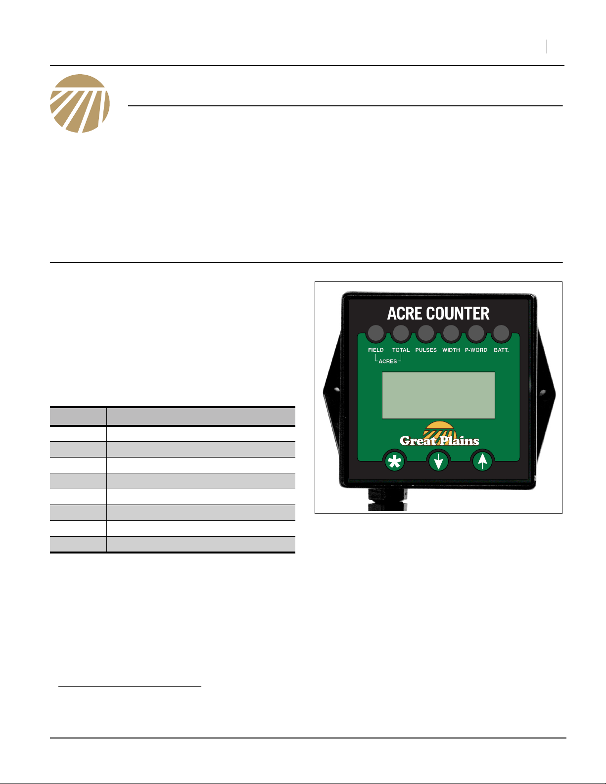
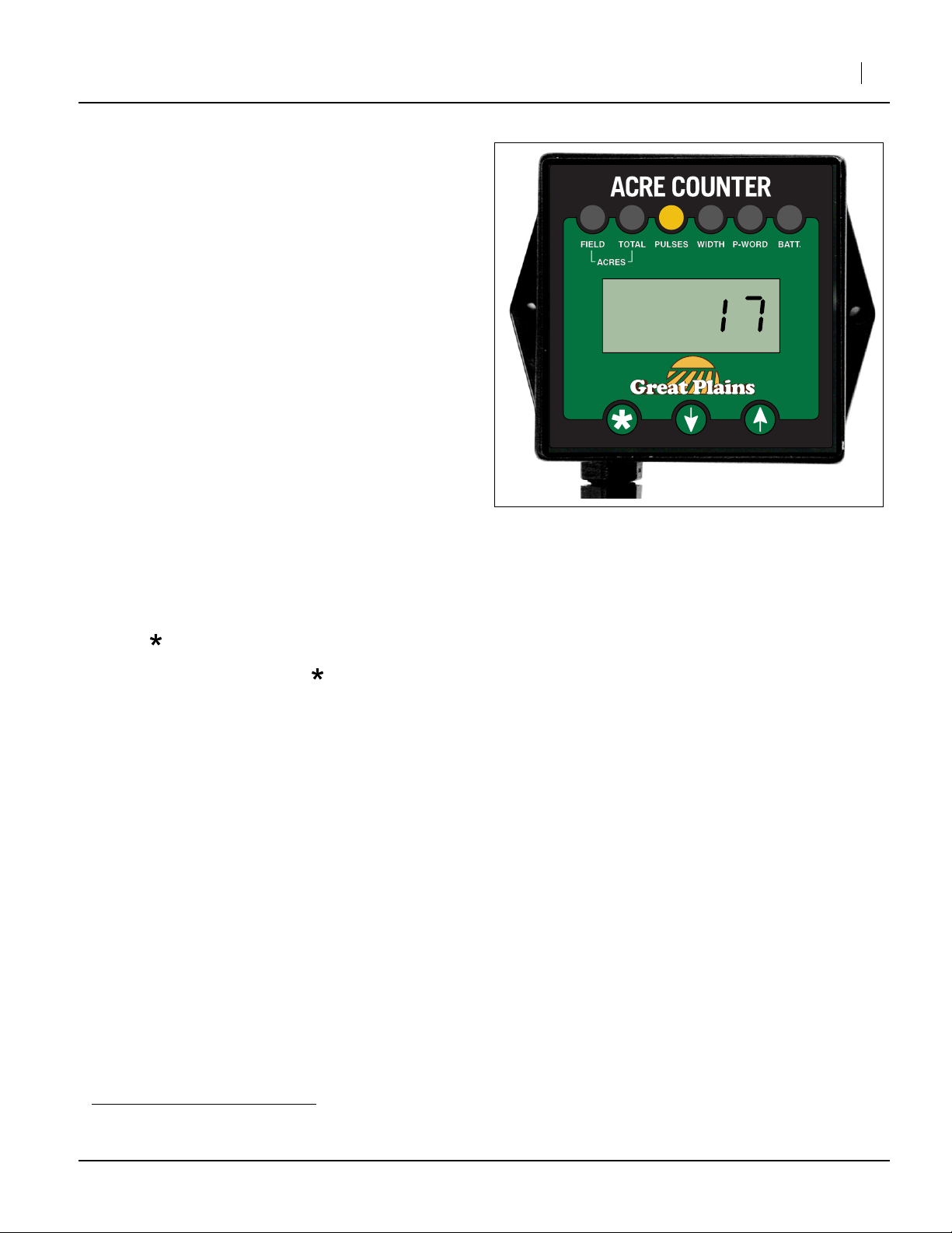
Figure 1
Electronic Acremeter
Programming the Acremeter
• If your drill was equipped with this acremeter from
production, it will have been supplied already programmed.
• If you ordered your acremeter and install it yourself, it
will need to be programmed.
• If your new Great Plains acremeter is not preprogrammed to your drill, see “Acremeter Operations”
on page 2 of this manual.
a. The electronic acremeter is compatible with all drills having a main or transfer 7/8 hex drive shaft on any section of the drill. The shaft must
be before any Drive Type, gearbox, lower, range, transmission or upper variable sprockets, and have only fixed sprockets and chains
between the drive wheel and the shaft.
Reference Information
• Find “Calibration For All Drill Models”on page 4.
• FInd “Drill Width Charts” on pages 7 and 8.
Tools Required
• basic hand tools.
34776
©Copyright 2014 Printed 2014/07/23 194-074M
Page 2
2 Electronic Acremeter
Acremeter Operations
A battery-operated electronic acre counter is supplied
with the drill. The display module for the system is
normally on the front face of the main toolbar near the
left gauge wheel.
The acremeter calculates and displays the field acres
and total acres accumulated.
The meter counts rotations of the main ground drive
shaft before the clutch. The meter tallies all movements
with the drill unfolded, whether planting or not.
The counter operates in one of two modes
•Insleep mode, the display is blank, and the counter
is accumulating acres. Sleep mode is entered if a
button is not pressed for 20 seconds. If a passcode is
set, it must be re-entered to change protected function
values.
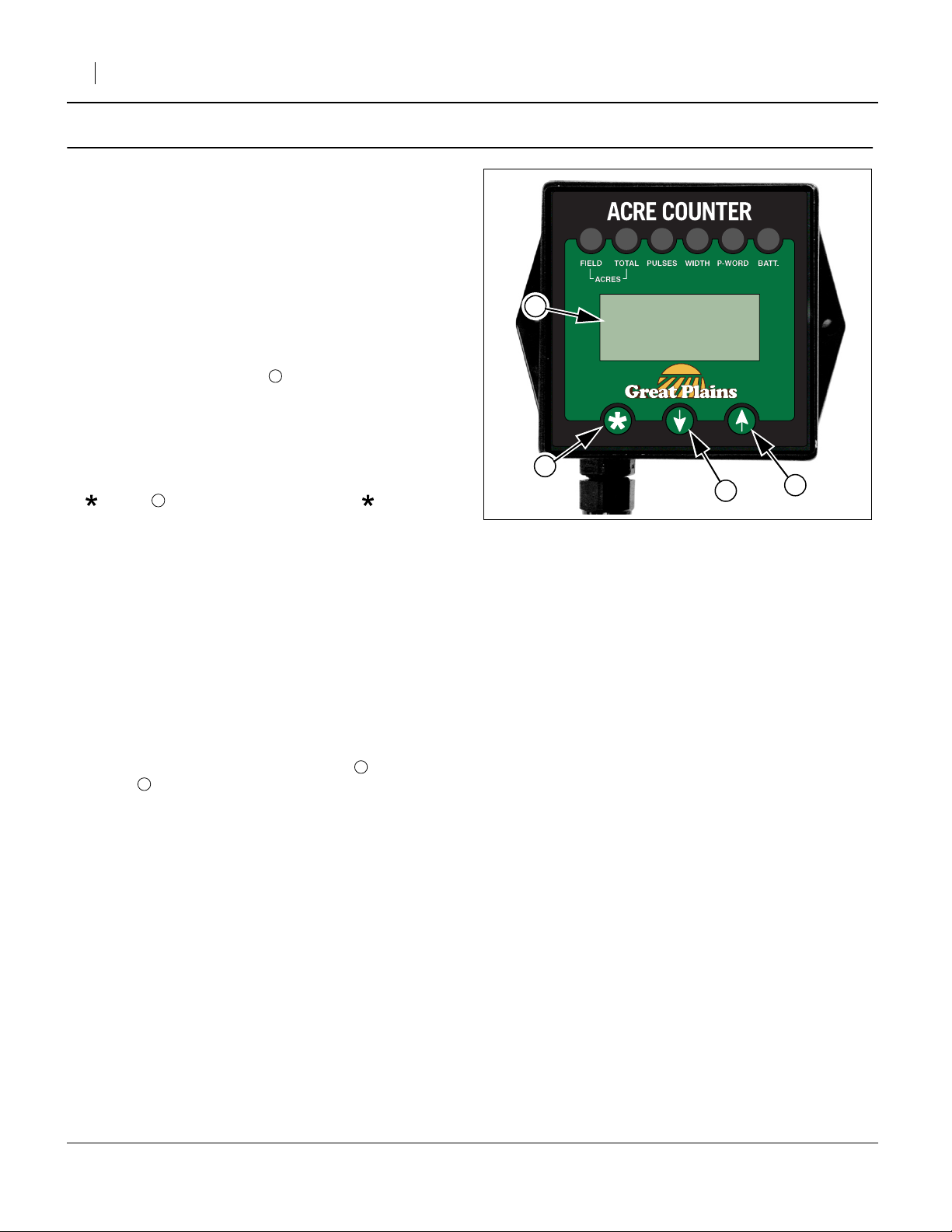
•Inentry mode, the display is on, and the operator can
enter values. To access entry mode, press the
button . If you continue to press the button, the
acre counter cycles through the available functions.
The LED light above the functions indicates which
function is selected.
The functions are:
2
1
Great Plains Mfg., Inc.
1
2
4
Figure 2
Acremeter Console
3
34776
FIELD Field Acres (always unprotected)
TOTAL Total Acres (passcode protectable)
PULSES Pulses per Mile (passcode protectable)
WIDTH Swath Width (passcode protectable)
P-WORD Password (enable/set/change/clear)
Note: U = USA units or acres
E = European units or hectares
Values are entered by pressing the UP and
DOWN arrow buttons. Holding a button
automatically increments that value. Long holds
increment faster than short holds. Pressing both
buttons simultaneously is used to reset some values
to 0.
•Tochange modes press and hold all 3 switches at
the same time. When pressed, the current mode will
scroll across the screen. “U” is for USA units, “E” is for
European (metric) units. When you have held all
3 switches for 5 seconds the mode will change.
This means you can check the mode at any time by
pressing the 3 keys and releasing them before
5 seconds has passed without changing anything.
Note: When you change modes, all the defaults are
4
reset to factory values so these will need to be set
properly for the machine. Also area accumulated
in one mode is not converted. It is reset to 0.
3
194-074M 2014/07/23
Page 3
Great Plains Mfg., Inc.
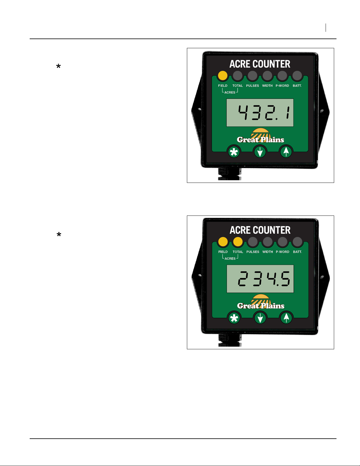
Field Acres
Refer to Figure 3
Press the button until the “FIELD” LED is lit. The digits
indicate the acres covered since the field acre counter
was last cleared to zero.
To clear the field acre count, depress the UP and DOWN
buttons for 2 seconds.
Note: If a passcode is set, it must be entered to clear the
total acre count.
Field acres count in tenths of an acre up to 9999.9 acres.
Installation Instructions 3
Total Acres
Refer to Figure 4
Press the button until both the “FIELD” and “TOTAL”
LEDs are lit. The digits indicate the acres covered since
the total acre counter was last cleared to zero.
To clear the total acre count, press and hold the UP and
DOWN buttons for 2 seconds.
Note: If a passcode is set, it must be entered to clear the
total acre count.
Total acres count from .1 to 99999 acres.
Figure 3
Field Acres Display
Figure 4
Total Acres Display
34813
34775
2014/07/23 194-074M
Page 4
4 Electronic Acremeter
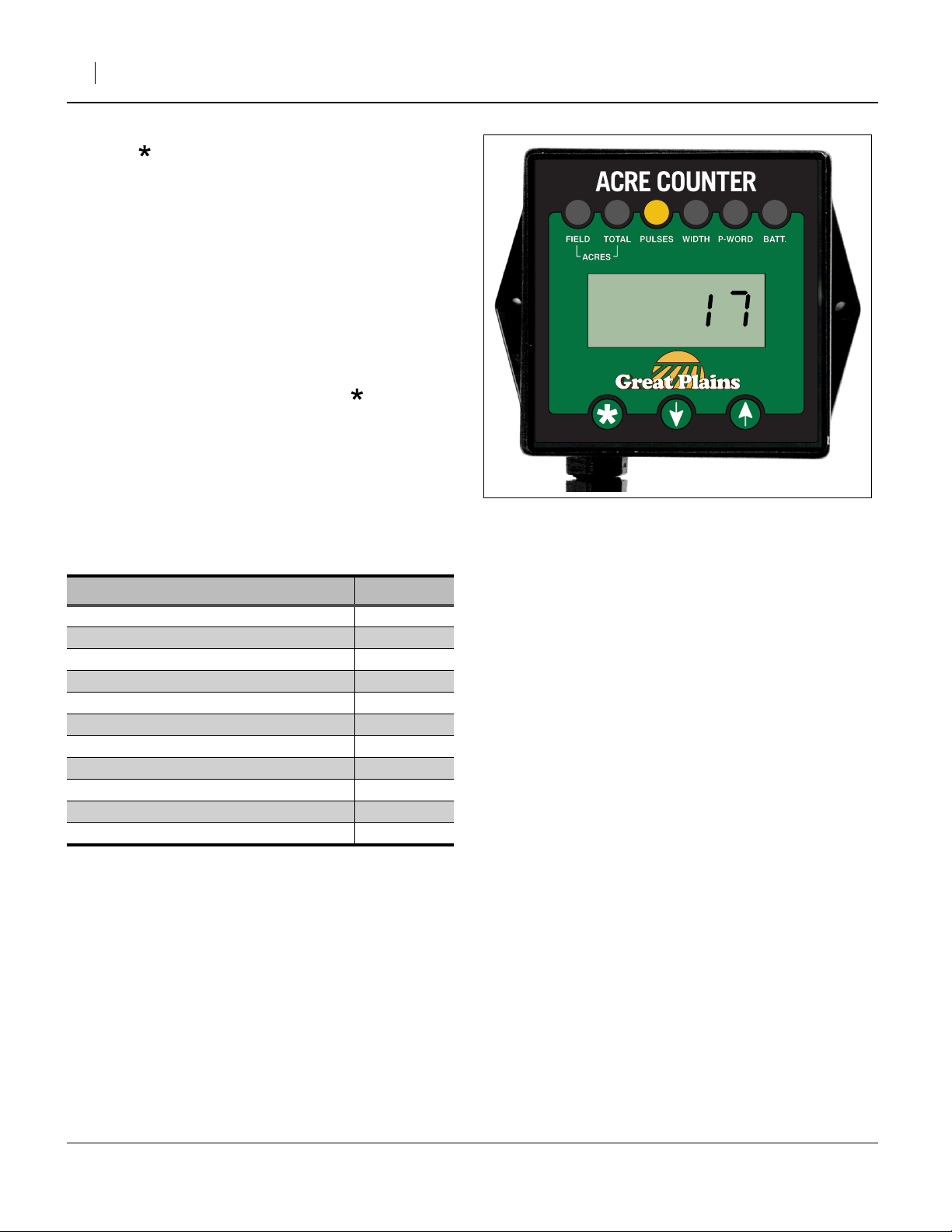
Pulses per 400 Feet of Travel
Press the button until the “PULSES” LED is lit. The
number in the display indicates how many pulses are
generated for every 400 feet (122 meters in “E” mode)
driven.
Note: If a passcode is set, it must be entered to adjust
the pulses per 400 feet (122 meters) of travel.
There are two methods to enter the pulses: known pulse
value and calibrating pulses per 400 feet (122 meters) of
travel.
Known Pulses Values
Refer to Figure 5
1. If you know the number, select it using the UP and
DOWN buttons. When you press the button, the
controller accepts the number in the display as the
new pulses per 400 feet (122 meters).
EXAMPLE:
Approximate pulses per 400 feet (122 meters) for
2S-2600, 3S-3000, 3S-4000 and 3S-5000: 17.
Calibration For All Drill Models
Great Plains Mfg., Inc.
Figure 5
Example:Pulses Per 400 Feet Entry
for 2S-2600/3000/4000/5000
34778
Model Calibration
2S-2600, 3S-3000, 3S-4000, 3S-5000 17
2N-2410, 2N-3010, 2N-2420, 2N-3020 31
706NT, 1006NT 36
1205NT 38
606NT 52
3P606NT, 3P806NT, 3P1006NT 46
3P500, 3P500V, 3P600 46
800EWD 52
1300EWD 16
3PT 1200, 1500 51
3PT 2000, 2400 49
194-074M 2014/07/23
Page 5
Great Plains Mfg., Inc.
Calibrating Pulses per 400 Feet of Travel
Note: Calibration is not recommended for the 2S-2600,
3S-3000, 3S-4000, or 3S-5000. Any value other
than 17 pulses per 400 feet results in reduced
accuracy of area measurement.
Refer to Figure 6
The acremeter can count pulses, and if the distance
driven is known, the pulses per 400 feet of travelbmay be
entered. Run the test with the drill unfolded, and the
openers raised.
Pulses Per Mile
Note: If you have documentation yet from a past design
of acremeter listing the pulse value stated as
pulses per mile, divide that value by 13.2 to arrive
at a new number. (5280 feet per mile/400 ft =
13.2). If you get a fraction round up to the next full
digit for the best accuracy.
PulsesCounted PerMile
Pulses Per 400 ft of Travel
-------------------------------------------------------
=
13.2
Installation Instructions 5
Pulses Per 400 Feet
To calibrate the pulses per 400 feet of travel, press and
hold the UP and DOWN buttons until “0” appears in the
PULSES display. The acre counter is now ready to count
shaft rotations.
Enter the tractor cab and drive 400 feet.
Press the button to wake up the acre counter. The
“PULSES” LED will again blink. The number displayed is
the pulses per 400 feet. Press the button to accept the
setting. The “PULSES” LED will stop blinking and remain
on.
Figure 6
Count Pulses Per 400 feet of Travel
34778
b. For more accurate calibration, operate for some multiple of 400 feet (say 1600 ft) divide the count by that multiple and round off.
2014/07/23 194-074M
Page 6
6 Electronic Acremeter
Width
To correctly calculate acres planted, the acremeter
needs the swath width of the drill.
Note: If a passcode has been set, it must be entered to
adjust WIDTH.
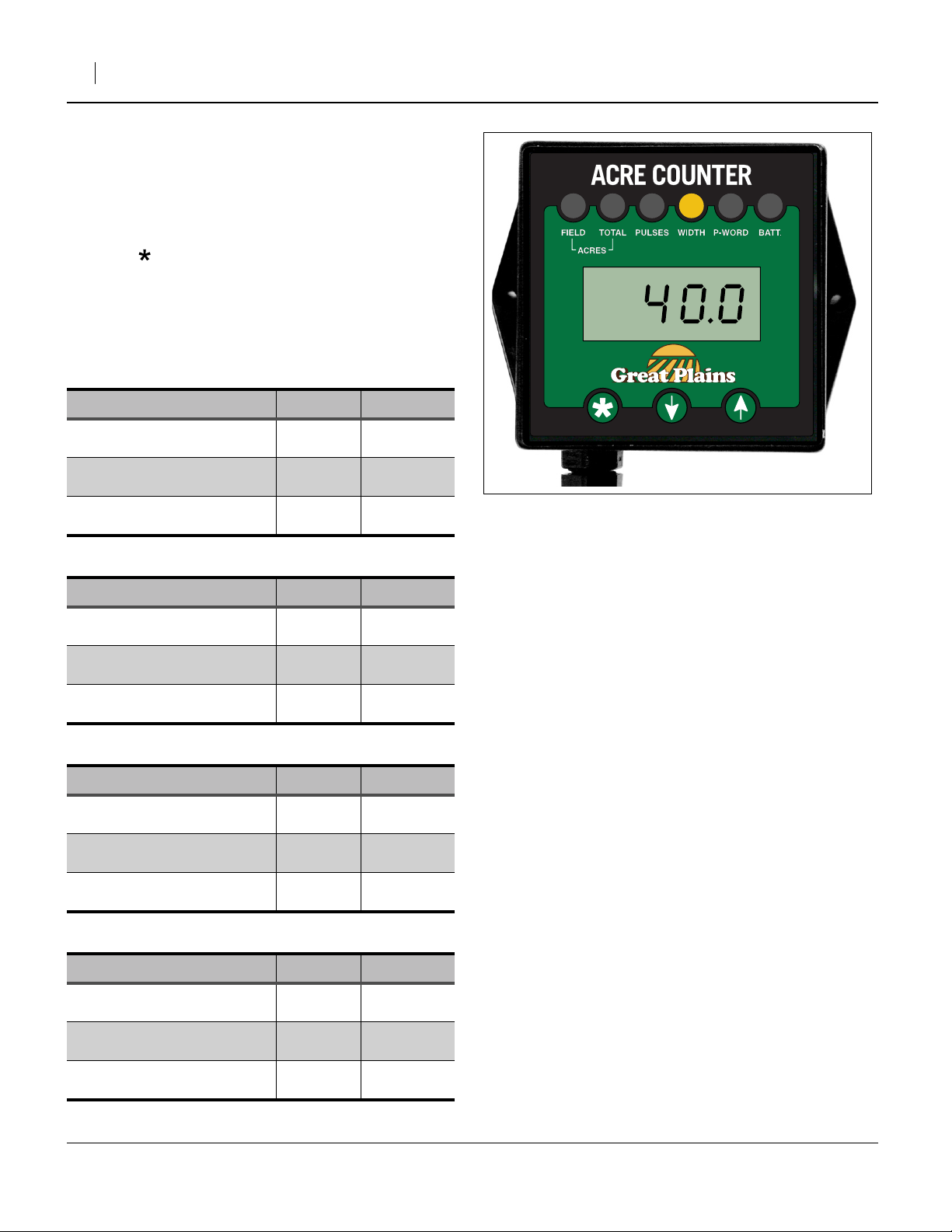
Refer to Figure 7
Press the button until the “WIDTH” LED is lit. The
number displayed is the swath width of your implement in
feet (the span between end row units, plus one row unit
spacing).
To adjust the width, press the UP and DOWN buttons.
The width can be adjusted from .1 to 99.9 feet, in tenths
of a foot.
Model Spacing Width
2S-2600/F/HD/HDF-3210 10 in.
2S-2600/F/HD/HDF-4275 7.5 in.
2S-2600/F/HD/HDF-5206 6 in.
26.7 feet
8.1 meters
26.3 feet
8.0 meters
26.0 feet
7.9 meters
Figure 7
Drill Width (Swath)
Great Plains Mfg., Inc.
34779
Model Spacing Width
3S-3000/F/HD/HDF-3610 10 in.
3S-3000/F/HD/HDF-4875 7.5 in.
3S-3000/F/HD/HDF-6006 6 in.
Model Spacing Width
3S-4000/F/HD/HDF-4810 10 in.
3S-4000/F/HD/HDF-6375 7.5 in.
3S-4000/F/HD/HDF-7806 6 in.
Model Spacing Width
3S-5000/F/HD/HDF-6010 10 in.
3S-5000/F/HD/HDF-8075 7.5 in.
3S-5000/F/HD/HDF-1006 6 in.
30.0 feet
9.1 meters
30.0 feet
9.1 meters
30.0 feet
9.1 meters
40.0 feet
12.2 meters
39.4 feet
12.0 meters
39.0 feet
11.9 meters
50.0 feet
15.2 meters
50.0 feet
15.2 meters
50.0 feet
15.2 meters
Note: Implement width in “U” mode is USA feet to one
decimal place.
Implement width in “E” mode is in meters to one
decimal place.
194-074M 2014/07/23
Page 7
Great Plains Mfg., Inc.
Installation Instructions 7
Drill Width Charts
Model Spacing Width
2N-2410-2810 10 in. 23.3 feet (7.1 meters)
2N-2410-3875 7.5 in. 23.8 feet (7.9 meters)
2N-3010-3610 10 in. 30.0 feet (9.1 meters)
2N-3010-4875 7.5 in. 30.0 feet (9.1 meters)
Model Spacing Width
2N-2420-2810 10 in. 23.3 feet (7.1 meters)
2N-2420-3875 7.5 in. 23.8 feet (7.9 meters)
2N-3020-3610 10 in. 30.0 feet (9.1 meters)
2N-3020-4875 7.5 in. 30.0 feet (9.1 meters)
Model Spacing Width
606NT-0975 7.5 in 5.6 feet (1.7 meters)
706NT-1075 7.5 in 6.3 feet (1.9 meters)
1006NT-1575 7.5 in 9.4 feet (2.9 meters)
1205NT-1975 7.5 in. 11.9 feet (3.6 meters)
3P606NT-0975 7.5 in 5.6 feet (1.7 meters)
3P806NT-1375 7.5 in 8.1 feet (2.5 meters)
3P1006NT-1575 7.5 in 9.4 feet (2.9 meters)
Model Spacing Width
3P600-0975 7.5 in 5.6 feet (1.7 meters)
3P600-1106 6 in 5.5 feet (1.7 meters)
3P500-0775 7.5 in 4.4 feet (1.3 meters)
3P500-0906 6 in 4.5 feet (1.4 meters)
3P500-0775 (V) 7.5 in 4.4 feet (1.3 meters)
3P500-0872 (V) 7.25 in 4.8 feet (1.5 meters)
3P500-0906 (V) 6 in 4.5 feet (1.4 meters)
Model Spacing Width
800-1275 7.5 in 8.1 feet (2.5 meters)
800-1506 6 in 7.5 feet (2.3 meters)
1300-1610 10 in 13.3 feet (4.1 meters)
1300-2175 7.5 in 13.1 feet (4.0 meters)
1300-2506 6 in 13.0 feet (4.0 meters)
2014/07/23 194-074M
Page 8
8 Electronic Acremeter
Model 1200/1210/1220 Spacing Width
1200-1410 (3PT) 10 in 11.7 feet (3.6 meters)
1200-1808 (3PT) 8 in 12.0 feet (3.6 meters)
1200-1975 (3PT) 7.5 in 11.9 feet (3.6 meters)
1200-2007 (3PT) 7 in 11.7 feet (3.6 meters)
1200-2406 (3PT) 6 in 12.0 feet (3.6 meters)
Model 1500/1510/1520 Spacing Width
1500-1810 (3PT) 10 in 15.0 feet (4.6 meters)
1500-2208 (3PT) 8 in 14.7 feet (4.5 meters)
1500-2475 (3PT) 7.5 in 15.0 feet (4.6 meters)
1500-2607 (3PT) 7 in 15.2 feet (4.6 meters)
1500-3006 (3PT) 6 in 15.0 feet (4.6 meters)
Great Plains Mfg., Inc.
Drill Width Charts (continued)
Model 2000/2010/2020 Spacing Width
2000-2410 (3PT) 10 in 20.0 feet (6.1 meters)
2000-3008 (3PT) 8 in 20.0 feet (6.1 meters)
2000-3275 (3PT) 7.5 in 20.0 feet (6.1 meters)
2000-3407 (3PT) 7 in 19.8 feet (6.0 meters)
2000-4006 (3PT) 6 in 20.0 feet (6.1 meters)
Model Spacing Width
2400-2810 (3PT) 10 in 23.3 feet (7.1 meters)
2400-3608 (3PT) 8 in 24.0 feet (7.3 meters)
2400-3875 (3PT) 7.5 in 23.8 feet (7.3 meters)
2400-4007 (3PT) 7 in 23.3 feet (7.1 meters)
2400-4806 (3PT) 6 in 24.0 feet (7.3 meters)
194-074M 2014/07/23
Page 9

Great Plains Mfg., Inc.
Passcode
The “P-WORD” function allows you to protect:
- the total acre count,
- pulses per 400 feet and
- width
settings with a 4-digit passcode. This prevents accidental
and malicious changes to those settings. As provided by
the factory, the passcode feature is disabled, and you
can modify those function values at any time.
Press the button until the “P-WORD” LED is lit. The
display reads either:
“Ent” (enter passcode) or
“dIS” (passcode disabled)
Enable and Set Passcode
The P-WORD display must show “dIS” in order to enable
and set a passcode on a unit which presently has no
passcode (see below for changing an existing
passcode).
Refer to Figure 8
Use the UP and DOWN buttons to select a passcode in
the range 0001 through 9999 (0000 disables).
Press button to accept the passcode. If the module
enters sleep mode before you press the button, the
passcode is not set.
Note: The protected function values remain unprotected
until the next time the module enters sleep mode.
Installation Instructions 9
Figure 8
Password Presently Disabled
34777
Using a Passcode
If the P-WORD display shows “Ent”, a passcode must be
entered, or the protected function values cannot be
changed.
Refer to Figure 9
Enter the passcode using the UP and DOWN buttons.
When your passcode is displayed, press the button to
test the passcode.
If the passcode is correct, you can change the protected
settings.
The protected settings are unprotected, and the
password remains viewable in the P-WORD display
function, until the module next enters sleep mode. When
button is next pressed, the passcode is again required
to change protected settings.
If the entered passcode is not correct, the protected
settings cannot be changed. When the “P-WORD”
function is selected again, “Ent” appears in the display.
Figure 9
Password Prompt “ENT”
34780
2014/07/23 194-074M
Page 10
10 Electronic Acremeter
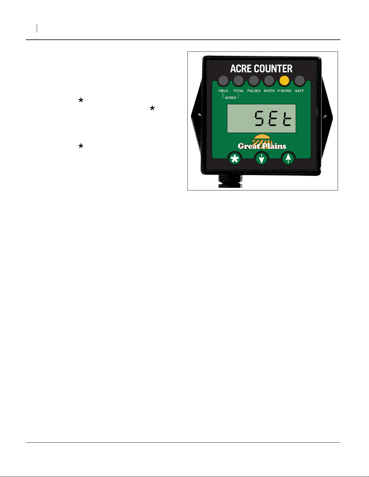
Changing the Passcode
To change an existing passcode, first enter the existing
password as described in ““Using a Passcode””.
Refer to Figure 10
While still in the P-WORD function display, select a new
passcode using the UP and DOWN buttons.
Press and hold the button until the “SEt” (setting
password) appears in the display. Release the button.
The number in the display is your new password. Be sure
to record it.
To disable the passcode, set the new password to 0000
(press and hold both UP and DOWN to do this quickly).
Press and hold the button until “dIS” (passcode
disabled) appears in the display.
If the passcode is forgotten, it can be disabled by
removing the batteries. In rental or managed commercial
operations, it is recommended that a tamper-evident seal
be affixed to the rear plate of the acre counter (securing
the battery compartment).
Great Plains Mfg., Inc.
Figure 10
Password Change Prompt
34810
194-074M 2014/07/23
Page 11
Great Plains Mfg., Inc.
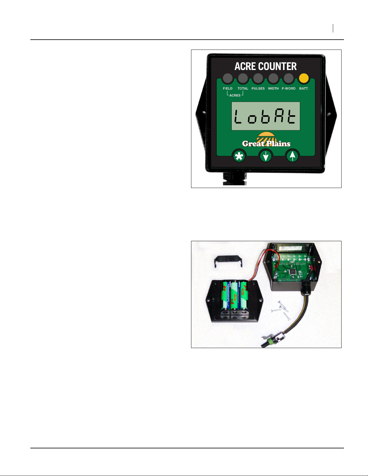
Battery Replacement
The battery operated acre counter uses 3 AA-size
alkaline batteries. Although the batteries typically last
between 5 and 10 years, they should be inspected
annually, as low batteries can leak corrosive chemicals,
and damage the electronic acremeter.
If battery replacement is needed, the acre counter
displays “LobAt” (low battery).
For battery inspection or replacement, dismount the acre
counter from the implement and remove the 4 screws on
the back of the case. This will separate the housing from
the rear plate. Replace the batteries with 3 high quality
AA alkaline batteries.
Note: The module is dust and splash resistant, but under
no circumstance should it be submerged in any
conductive, corrosive or flammable liquid.
Installation Instructions 11
Figure 11
Replacing Batteries
Figure 12
Replacing Batteries
34812
34761
2014/07/23 194-074M
Page 12

12 Electronic Acremeter
Reference Information
Accuracy Considerations
Many factors can affect the accuracy of your electronic
acremeter:
• Tire Size and Tire Pressure
• Seeding Overlap
The area reported by the meter will be higher than
the actual field area if passes overlap.
• Soil Conditions
The meter configuration was programmed for nominal
tire slippage. Extreme conditions, wet or muddy
conditions, min-till/no-till conditions and some native
grass conditions may change wheel slippage,
resulting in slightly inaccurate area tallies.
Display
Liquid Crystal Displays (LCDs) do not function optimally
in extremely cold conditions (conditions colder than you
are likely to be planting in). If the display is blank, hard to
read, or sluggish, and the weather is near freezing, the
LCD is likely responding to the temperature.
The battery, rotational sensor and computer electronics
are still operating, however, and read-out will be possible
once the meter warms up. Do not use direct application
of hot air, fluids or metal to warm up the meter, or you
may damage it.
Great Plains Mfg., Inc.
194-074M 2014/07/23
Page 13

Great Plains Mfg., Inc.
Acremeter Installation
Prepare Drill
Note: The following examples and instructions are for
the 2S-2600. Use the instructions as a guide while
referring to the illustration for your specific drill’s
acremeter placement starting at “Acremeter
Diagrams” on page 16 through page 28.
The following installation instructions for installing
the sensor, actuator and meter also use the
2S-2600 for the example and assembly steps. Use
these instructions as a guide making sure to
consult the kit contents for your particular drill
starting at “Acremeter Kits” on page 29 through
page 33.
Refer to Figure 13
1. The work may be performed with the drill raised or
lowered. If lowered, a wrench may not be needed, as
the drive shaft cannot rotate.
Installation Instructions 13
2
1
Identify the Mounting Location
2. SENSOR: If the drill does not presently have a
shaft-mounted acremeter, look for a7⁄8inch
hexagonal drive shaft with the drive clutch
connected (this is usually the main jack shaft).
Mount the sensor on the two-hole bearing flangette
at one end of this shaft.
3. METER: Mount the acremeter console on the front
face of the main frame toolbar in a location close
to the sensor.
Note: For 2S-2600 model: Mount meter on the right
hand box frame.
For 3S-3000/4000/5000 models: Mount meter on
the center box frame and the meter will remote
mount on the left hand box frame.
1
2
Figure 13
Shaft and Meter
(3S-3000/4000/5000)
34817
2014/07/23 194-074M
Page 14

14 Electronic Acremeter
Install Sensor
Refer to Figure 14 (this example depicts the 2S-2600)
4. Select one each new:
13
168-491D ACREMETER SWITCH MOUNT
28
221398 SWITCH
and two sets new:
22
804-036C WASHER FLAT 5/16 SAE PLT
16
801-067C SCREW RD HD 8-32 X 1 1/2LG PLT
23
804-043C WASHER LOCK #8
20
803-064C NUT HEX 8-32
and four new:
25
804-088C WASHER FLAT #8 SAE PLT
5. Mount the u-shaped face of the switch mount to
the face of the bearing flangette using the existing
flange bolts , new flat washers and existing
flange nuts .
6. Attach the flat face of the switch mount (part
facing the sensor) using the screws , flat
washers , lock washers and hex nuts .
7. Attach the pickup sensor to the sensor bracket.
Secure the ground wire to one of the mounting
screws. Slide the sensor so it is no more than1⁄8inch
from the magnet actuator. Do not allow the sensor to
touch the magnet actuator. Leave screws finger tight
until Step 9.
50 22
51
16
25 23 20
13
13
Great Plains Mfg., Inc.
16
25
13
28
51
22
25
23
20
3
50
Figure 14
Install Sensor (2S-2600)
Note: The individual wire on the sensor is a frame
ground wire that is designed to protect the acre
counter from any static discharge that it may
encounter. It should be attached to the metal on
the drill somewhere.
3
34818
194-074M 2014/07/23
Page 15

Great Plains Mfg., Inc.
Install Actuator
Refer to Figure 15 (this example depicts the 2S-2600)
8. Orient the actuator so that the snap tabs cannot
entangle debris during rotation (which is top-of-shaftforward for the enumerated drill models on page 1).
Note: The acremeter counts rotations of the ground
drive shaft, this is field travelled acres not field
planted acres.
9. Select one new:
30
540002-1 7/8 HEX SNAP-ON ACTUATOR
30
Installation Instructions 15
Install the two halves of the magnet actuator
3
around the shaft and slide the actuator together.
Position the magnet actuator next to the bearing
mount.
Note: Take care when sliding the actuator together to
avoid breaking one of the tabs.
Note: The pulse counter is not rotation direction
sensitive but the position of the sensor to the
spinning magnet actuator is. The sensor should
have the end opposite from the connection
harness towards the shaft and the wide dimension
of the switch housing centered on the plastic
wheel width,1⁄8inch gap is recommended.
Install Meter
Refer to Figure 16
When mounting the acremeter console to the drill frame,
select a location close to the pickup sensor which
allows easy access for reading or adjustments. Pick a
location which allows the console to be mounted in a
vertical position.
Refer to Figure 16 (this example depicts the 2S-2600)
10. Select a ground driven shaft with easy access.
Select one each new:
27
823-423C ELECTRONIC ACRE METER
14
168-492D ACREMETER MOUNT
26
806-051C U-BOLT 3/8-16 X 6 1/32 X 7
29
221399 CONSOLE
and two sets new:
21
804-013C WASHER LOCK SPRING 3/8 PLT
19
803-014C NUT HEX 3/8-16 PLT
17
802-826C HHCS #10-24X1 1/4 PLT GR5
24
804-054C WASHER LOCK #10
18
803-001C NUT HEX 10-24 PLT
1
30
Figure 15
Attach Actuator (2S-2600)
1
2
27
24
34820
18
26
On the front face of the main toolbar, attach
mount with U-bolt using lock washer
springs and hex nuts . Attach acremeter to
14 26
21 19 27
mount using screws , lock washers and hex
18
nuts .
2
17 24
11. Connect the cable from the sensor pickup to the acre
counter console. Through the hole in the mount,
17
27
19
Figure 16
Mount Meter (2S-2600)
14
21
34820
windup and tie out of the way any extra cable.
2014/07/23 194-074M
Page 16

16 Electronic Acremeter
Acremeter Diagrams
Acre Meter Location 2N-2410, 2N-3010, 2N-2420, 2N-3020
Great Plains Mfg., Inc.
Figure 17
2N-2410, 2N3010, 2N-2420, 2N-3020
Kit: 197-187A
194-074M 2014/07/23
36324
Page 17

Great Plains Mfg., Inc.
Acre Meter Location 606NT
Installation Instructions 17
Figure 18
36325
606NT
Kit: 152-327A
2014/07/23 194-074M
Page 18

18 Electronic Acremeter
Acre Meter Location 706NT (LH)
Great Plains Mfg., Inc.
Figure 19
36330
706NT
Kit: 152-326A
194-074M 2014/07/23
Page 19

Great Plains Mfg., Inc.
Acre Meter Location 706NT(RH) Dual Seed/Native Grass
Installation Instructions 19
Figure 20
36331
706NT
Kit: 152-328A
2014/07/23 194-074M
Page 20

20 Electronic Acremeter
Acre Meter Location 1006NT (LH) or 1205NT
Great Plains Mfg., Inc.
Figure 21
36332
1006NT (LH) or 1205NT
Kit: 152-326A
194-074M 2014/07/23
Page 21

Great Plains Mfg., Inc.
Acre Meter Location 1006NT (RH)
Installation Instructions 21
Figure 22
36333
1006NT (RH)
Kit: 152-326A
2014/07/23 194-074M
Page 22

22 Electronic Acremeter
Acre Meter Location 3P500, 3P500 (V), 3P600, 3P606NT
Great Plains Mfg., Inc.
Figure 23
36326
3P500, 3P500 (V), 3P600, 3P606NT
Kit: 152-327A
194-074M 2014/07/23
Page 23

Great Plains Mfg., Inc.
Acre Meter Location 3P806NT
Installation Instructions 23
Figure 24
36327
3P806NT
Kit: 152-327A
2014/07/23 194-074M
Page 24

24 Electronic Acremeter
Acre Meter Location 3P1006NT (RH) Dual Seed or Native Grass
also for older drills with two independent drive shafts
Great Plains Mfg., Inc.
Figure 25
3P1006NT (right hand)
Kit: 152-329A
194-074M 2014/07/23
36328
Page 25

Great Plains Mfg., Inc.
Acre Meter Location 3P1006NT (LH)
Installation Instructions 25
Figure 26
36329
3P1006NT (left hand)
Kit: 152-327A
2014/07/23 194-074M
Page 26

26 Electronic Acremeter
Acre Meter Location 800 and 1300
Great Plains Mfg., Inc.
Figure 27
36334
800 and 1300
Kit: 175-311A
194-074M 2014/07/23
Page 27

Great Plains Mfg., Inc.
Acre Meter Location 3PT 1200, 1500, 2000, 2400
Installation Instructions 27
Figure 28
36348
3PT 1200, 1500, 2000, 2400
Kit: 118-260A
2014/07/23 194-074M
Page 28

28 Electronic Acremeter
Acre Meter Location 3PT 1200, 1500, 2000 Optional
Great Plains Mfg., Inc.
Figure 29
36349
3PT 1200, 1500, 2000
Kit: 118-260A
194-074M 2014/07/23
Page 29

Great Plains Mfg., Inc.
Installation Instructions 29
Acremeter Kits
Part Lists
The part call-out numbers in this list match all Figures in
these installation instructions. Part descriptions match
those in your updated Parts Manual.
Kit: 194-073A Models: 2S-2600, 3S-3000, 3S-4000, 3S-5000 ELECTRONIC ACREMETER
Callout Part Number Part Description
Quantities are units (“ea”).
11
12
13
14
15
16
17
18
19
20
21
22
23
24
25
26
27
194-073A MIN-TILL ELECTRONIC ACRE METER
194-074M MANUAL ELECTRONIC ACRE METER
168-491D ACREMETER SWITCH MOUNT
168-492D ACREMETER MOUNT
800-269C CABLE TIE 33LG
801-067C SCREW RD HD 8-32 X 1 1/2LG PLT
802-826C HHCS #10-24X1 1/4 PLT GR5
803-001C NUT HEX 10-24 PLT
803-014C NUT HEX 3/8-16 PLT
803-064C NUT HEX 8-32
804-013C WASHER LOCK SPRING 3/8 PLT
804-036C WASHER FLAT 5/16 SAE PLT
804-043C WASHER LOCK #8
804-054C WASHER LOCK #10
804-088C WASHER FLAT #8 SAE PLT
806-051C U-BOLT 3/8-16 X 6 1/32 X 7
823-423C ELECTRONIC ACRE METER
28
29
30
2014/07/23 194-074M
221398 SWITCH
221399 CONSOLE
540002-1 7/8 HEX SNAP-ON ACTUATOR
Page 30

Great Plains Mfg., Inc.
30 Electronic Acremeter
Kit: 197-187A Models: 2N-2410, 2N-3010, 2N-2420, 2N-3020 ELECTRONIC ACREMETER
Callout Part Number Part Description
31
13
14
12
15
16
19
20
21
22
23
25
32
27
540003-1 1" RD SNAP-ON ACTUATOR
168-491D ACREMETER SWITCH MOUNT
168-492D ACREMETER MOUNT
194-074M MANUAL ELECTRONIC ACRE METER
800-269C CABLE TIE 33LG
801-067C SCREW RD HD 8-32 X 1 1/2LG
803-014C NUT HEX 3/8-16 PLT
803-064C NUT HEX 8-32
804-013C WASHER LOCK SPRING 3/8 PLT
804-036C WASHER FLAT 5/16 SAE PLT
804-043C WASHER LOCK #8
804-088C WASHER FLAT #8 SAE PLT
806-266C U-BOLT 3/8-16 X 8 1/32 X 7
823-423C ELECTRONIC ACRE METER
Kit: 152-326A Models: 706NT, 1006NT, 1205NT ELECTRONIC ACREMETER
Callout Part Number Part Description
34
33
14
12
35
16
36
37
20
21
38
22
23
25
39
27
540005-1 3/4 HEX SNAP-ON ACTUATOR
152-599D ACREMETER SENSOR MOUNT 2.81
168-492D ACREMETER MOUNT
194-074M MANUAL ELECTRONIC ACRE METER
800-377C HOSE CLIP 13/16 ID 1/2 MOUNT
801-067C SCREW RD HD 8-32 X 1 1/2LG
803-014C NUT HEX 3/8-16 PLT
803-020C NUT HEX 1/2-13 PLT
803-064C NUT HEX 8-32
804-013C WASHER LOCK SPRING 3/8 PLT
804-015C WASHER LOCK SPRING 1/2 PLT
804-036C WASHER FLAT 5/16 SAE PLT
804-043C WASHER LOCK #8
804-088C WASHER FLAT #8 SAE PLT
806-263C U-BOLT 3/8-16 X 4 1/32 X 5
823-423C ELECTRONIC ACRE METER
194-074M 2014/07/23
Page 31

Great Plains Mfg., Inc.
Installation Instructions 31
Kit: 152-327A Models: 606NT, 3P606NT, 3P806NT, 3P1006NT, 3P500, 3P500V, 3P600
Callout Part Number Part Description
43
44
14
12
15
16
19
20
21
22
23
25
45
27
540002-1 7/8 HEX SNAP-ON ACTUATOR
152-601D 7/8 HEX SENSOR MOUNT
168-492D ACREMETER MOUNT
194-074M MANUAL ELECTRONIC ACRE METER
800-269C CABLE TIE 33LG
801-067C SCREW RD HD 8-32 X 1 1/2LG PLT
803-014C NUT HEX 3/8-16 PLT
803-064C NUT HEX 8-32
804-013C WASHER LOCK SPRING 3/8 PLT
804-036C WASHER FLAT 5/16 SAE PLT
804-043C WASHER LOCK #8
804-088C WASHER FLAT #8 SAE PLT
806-265C U-BOLT 3/8-16 X 3 1/32 X 5
823-423C 3P LOUP ACREMETER
Kit: 152-329A Models: 3P1006NT DUAL SEED OR NATIVE GRASS ELECTRONIC ACREMETER
(also earlier model drills with two independent drive shafts)
Callout Part Number Part Description
28
43
63
44
12
15
16
20
22
23
25
27
62
221398 SWITCH
540002-1 7/8 HEX SNAP-ON ACTUATOR
152-329A 3P DUAL SEED/NG ACREMETER
152-601D 7/8 HEX SENSOR MOUNT
194-074M MANUAL ELECTRONIC ACRE METER
800-269C CABLE TIE 33LG
801-067C SCREW RD HD 8-32 X 1 1/2LG
803-064C NUT HEX 8-32
804-036C WASHER FLAT 5/16 SAE PLT
804-043C WASHER LOCK #8
804-088C WASHER FLAT #8 SAE PLT
823-423C 3P LOUP ACREMETER
823-434C HARNESS EXT. 10’ 2 PIN WP
2014/07/23 194-074M
Page 32

32 Electronic Acremeter
Kit: 175-311A Models: 800 and 1300 ELECTRONIC ACREMETER
Callout Part Number Part Description
Great Plains Mfg., Inc.
43
14
46
12
15
16
19
20
21
22
23
25
47
27
540002-1 7/8 HEX SNAP-ON ACTUATOR
168-492D ACREMETER MOUNT
175-489D EW SENSOR MOUNT
194-074M MANUAL ELECTRONIC ACRE METER
800-269C CABLE TIE 33LG
801-067C SCREW RD HD 8-32 X 1 1/2LG PLT
803-014C NUT HEX 3/8-16 PLT
803-064C NUT HEX 8-32
804-013C WASHER LOCK SPRING 3/8 PLT
804-036C WASHER FLAT 5/16 SAE PLT
804-043C WASHER LOCK #8
804-088C WASHER FLAT #8 SAE PLT
806-264C U-BOLT 3/8-16 X 5 1/32 X 5
823-423C 3P LOUP ACREMETER
Kit: 118-260A Models: 3PT 1200,1210,1220/3-PT 1500,1510,1520/3-PT 2000,2010,2020/3PT 2400
Callout Part Number Part Description
41
40
14
12
16
42
19
20
21
22
23
25
26
27
540005-1 3/4 HEX SNAP-ON ACTUATOR
118-071D 3PT ACREMETER SWITCH MOUNT
168-492D ACREMETER MOUNT
194-074M MANUAL ELECTRONIC ACRE METER
801-067C SCREW RD HD 8-32 X 1 1/2LG PLT
802-128C HHCS 1/2-13X2 GR5
803-014C NUT HEX 3/8-16 PLT
803-064C NUT HEX 8-32
804-013C WASHER LOCK SPRING 3/8 PLT
804-036C WASHER FLAT 5/16 SAE PLT
804-043C WASHER LOCK #8
804-088C WASHER FLAT #8 SAE PLT
806-051C U-BOLT 3/8-16 X 6 1/32 X 7
823-423C ELECTRONIC ACRE METER
194-074M 2014/07/23
Page 33

Great Plains Mfg., Inc.
Installation Instructions 33
Kit: 152-328A Models: 706NT, 1006NT DUAL SEED OR NATIVE GRASS ELECTRONIC ACREMETER
Callout Part Number Part Description
50
51
61
48
12
49
52
15
53
16
54
55
19
56
20
57
21
221398 SWITCH
540004-1 1 1/4 RD SNAP-ON ACTUATOR
152-328A NO-TILL DUAL SEED/NG ACREME
152-600D NG/DUAL SENSOR MOUNT
194-074M MANUAL ELECTRONIC ACRE METER
197-164H ACREMETER HUB WELDMENT
800-141C SNAP RING EXT F/PEERLESS G.
800-269C CABLE TIE 33LG
800-377C HOSE CLIP 13/16 ID 1/2 MOUNT
801-067C SCREW RD HD 8-32 X 1 1/2LG
802-078C HHCS 1/4-20X5/8 GR5
802-258C HHCS 1/2-13X1 GR5
803-014C NUT HEX 3/8-16 PLT
803-020C NUT HEX 1/2-13 PLT
803-064C NUT HEX 8-32
804-007C WASHER FLAT 1/4 SAE PLT
804-013C WASHER LOCK SPRING 3/8 PLT
58
23
25
39
27
59
60
804-015C WASHER LOCK SPRING 1/2 PLT
804-043C WASHER LOCK #8
804-088C WASHER FLAT #8 SAE PLT
806-263C U-BOLT 3/8-16 X 4 1/32 X 5
823-423C 3P LOUP ACREMETER
823-434C HARNESS EXT. 10’ 2 PIN WP
890-849C SPLINED ACREMETER MOUNT
Abbreviations
EA Each LG Long
GR Grade 5 MIN-TILL Minimum Tillage
HD Head PLT Plated
HHCS Hex Head Cap Screw RD Round
LCD Liquid Crystal Display SAE Society of Automotive Engineers (standard)
LED Light-Emitting Diode
2014/07/23 194-074M
Page 34

34 Electronic Acremeter
Great Plains Mfg., Inc.
Great Plains Manufacturing, Inc.
Corporate Office P.O. Box 5060
Salina, Kansas 67402-5060 USA
194-074M 2014/07/23
 Loading...