

Page 1

Installation, Operation and
Maintenance
195-075A, 195-076A, 195-077A, 195-078A
Electric Clutch Package
2- and 3-Section Drills
Manufacturing, Inc.
www.greatplainsmfg.com
Read this manual entirely. When you see this alert symbol, the subsequent
instructions and warnings are serious - follow without exception. Your life and
!
the lives of others depend on it!
28072
Cover illustration may not show specific package ordered.
© Copyright 2008 Printed 03/24/2009 195-073M
Page 2

Page 3

Great Plains Manufacturing, Inc.
Table of Contents
Important Safety Information ....................................1
General Information ...................................................3
Notations and Conventions ..........................................3
Call-Outs ..................................................................3
Pre-Assembly Preparation ........................................4
Before You Start...........................................................4
Tools Required .............................................................4
Work Location ..............................................................4
Prepare Drill .................................................................4
Install Kit.......................................................................4
2S-2600 Main Box Only Installation..........................5
Update 2S-2600 Left Hand Drive .................................5
Remove 2S-2600 LH Linkage ..................................5
Remove 2S-2600 LH Shaft and Clutch ....................5
Disassemble 2S-2600 LH Clutch..............................6
Pre-Assemble 2S-2600 LH Clutch............................7
Prepare New 2S-2600 LH Power Shaft....................7
Install New 2S-2600 LH Power Shaft .......................8
Install 2S-2600 LH Clutch.........................................9
2S-2600 LH Closeout .............................................10
Update 2S-2600 Right Hand Drive.............................11
Remove 2S-2600 RH Linkage................................11
Release 2S-2600 RH Drive Shaft...........................11
Disassemble 2S-2600 RH Clutch...........................12
Pre-Assemble 2S-2600 RH Clutch.........................12
Install 2S-2600 RH Clutch ......................................13
2S-2600 RH Closeout.............................................14
Install 2S-2600 Electronics.........................................14
2S-2600F & 2S-2600 Small Seeds Installation .......15
Update 2S-2600F/SGS Left Hand Drive ....................15
Remove 2S-2600F/SGS LH Linkage......................15
Remove 2S-2600F/SGS LH Shaft and Clutch........16
Remove 2S-2600F/SGS LH Power Shaft...............16
Disassemble 2S-2600F/SGS LH Clutch.................17
Pre-Assemble 2S-2600F/SGS LH Clutch...............17
Prepare New 2S-2600F/SGS LH Power Shaft.......17
Install New 2S-2600F/SGS LH Power Shaft ..........18
Install 2S-2600F/SGS LH Clutch............................19
2S-2600F/SGS LH Closeout ..................................20
Update 2S-2600F/SGS Right Hand Drive ..................21
Remove 2S-2600F/SGS RH Linkage.....................21
Release 2S-2600F/SGS RH Drive Shaft................ 21
Disassemble 2S-2600F/SGS RH Clutch................ 22
Pre-Assemble 2S-2600F/SGS RH Clutch.............. 22
Install 2S-2600F/SGS RH Clutch ........................... 23
2S-2600F/SGS RH Closeout .................................24
Install 2S-2600F/SGS Electronics.............................. 24
2S Electrical Installation............................................. 25
Install 2S Height Switch .........................................25
Install 2S Drill Cables ............................................. 26
3S-3000 Main Box Only Installation ....................... 27
Update 3S-3000 Left Hand Drive............................... 27
Remove 3S-3000 LH Linkage ................................ 27
Remove 3S-3000 LH Shaft and Clutch .................. 27
Disassemble 3S-3000 LH Clutch ........................... 28
Pre-Assemble 3S-3000 LH Clutch ......................... 28
Prepare New 3S-3000 LH Power Shaft .................29
Install New 3S-3000 LH Power Shaft..................... 29
Install 3S-3000 LH Clutch ......................................30
3S-3000 LH Closeout............................................. 31
Update 3S-3000 Center Drive.................................... 32
Remove 3S-3000 Center Components .................. 32
Install 3S-3000 CTR Clutch Bearing ...................... 33
Install 3S-3000 CTR Driven Shaft .......................... 33
Prepare 3S-3000 CTR Driving Shaft...................... 34
Pre-Assemble 3S-3000 CTR Clutch ......................34
Install 3S-3000 CTR Clutch.................................... 35
3S-3000 Center Closeout....................................... 36
Update 3S-3000 Right Hand Drive ............................ 36
Remove 3S-3000 RH Linkage ...............................36
Replace 3S-3000 RH Drive Shafts......................... 37
Disassemble 3S-3000 RH Clutch........................... 38
Pre-Assemble 3S-3000 RH Clutch......................... 38
Install 3S-3000 RH Clutch...................................... 39
3S-3000 RH Closeout ............................................ 41
Install 3S-3000 Electronics ........................................ 41
3S-3000F & 3S-3000 Small Seeds Installation....... 42
Update 3S-3000F/SGS Left Hand Drive .................... 42
Remove 3S-3000F/SGS LH Linkage ..................... 42
Remove 3S-3000F/SGS LH Shaft and Clutch ....... 43
Disassemble 3S-3000F/SGS LH Clutch ................44
Pre-Assemble 3S-3000F/SGS LH Clutch ..............44
© Copyright 2008. All rights Reserved.
Great Plains Manufacturing, Inc. providesthis publication “as is” without warranty of any kind, either expressed or implied. While every precaution has been taken in the preparation
of this manual, Great Plains Manufacturing, Inc. assumes no responsibility for errors or omissions. Neither is any liability assumed for damages resulting from the use of the information contained herein. Great Plains Manufacturing, Inc. reserves the right to revise and improve its products as it sees fit. This publication describes the state of this product at
the time of its publication, and may not reflect the product in the future.
The following are trademarks of Great Plains Mfg., Inc.: Application Systems, Ausherman, Land Pride, Great Plains
All other brands and product names are trademarks or registered trademarks of their respective holders.
03/24/2009 195-073M
Great Plains Manufacturing, Incorporated Trademarks
Printed in the United States of America.
Page 4

Electric Clutch Package Great Plains Manufacturing, Inc.
Prepare New 3S-3000F/SGS LH Power Shaft....... 44
Install New 3S-3000F/SGS LH Power Shaft.......... 45
Install 3S-3000F/SGS LH Clutch ........................... 46
3S-3000F/SGS LH Closeout.................................. 47
Update 3S-3000F/SGS Center Drive......................... 48
Remove 3S-3000F/SGS Center Components ....... 48
Install 3S-3000F/SGS CTR Driven Shaft ............... 49
Prepare 3S-3000F/SGS CTR Driving Shaft........... 50
Pre-Assemble 3S-3000F/SGS CTR Clutch............ 50
Install 3S-3000F/SGS CTR Clutch......................... 51
3S-3000F/SGS Center Closeout............................ 52
Update 3S-3000F/SGS Right Hand Drive.................. 52
Remove 3S-3000F/SGS RH Linkage..................... 52
Replace 3S-3000F/SGS RH Drive Shafts.............. 53
Disassemble 3S-3000F/SGS RH Clutch................ 54
Pre-Assemble 3S-3000F/SGS RH Clutch.............. 55
Install 3S-3000F/SGS RH Clutch........................... 56
3S-3000F/SGS RH Closeout .................................58
Install 3S-3000F/SGS Electronics.............................. 58
3S-3000/F/SGS Electrical Installation........................ 59
Install 3S-3000 Height Switch ................................ 59
Install 3S-3000/F/SGS Drill Cables........................ 60
3S-4000 Installation ................................................. 61
Update 3S-4000 Left Hand Drive............................... 61
Remove 3S-4000 LH Linkage................................ 61
Remove 3S-4000 LH Shaft and Clutch.................. 61
Disassemble 3S-4000 LH Clutch ........................... 62
Pre-Assemble 3S-4000 LH Clutch ......................... 63
Prepare New 3S-4000 LH Power Shaft .................63
Install New 3S-4000 LH Power Shaft..................... 63
Install 3S-4000 LH Clutch ......................................64
3S-4000 LH Closeout............................................. 65
Update 3S-4000 Center Drive.................................... 66
Remove 3S-4000 CTR Linkage ............................. 66
Remove 3S-4000 CTR Mechanical Clutch ............66
Disassemble 3S-4000 CTR Clutch ........................67
Pre-Assemble 3S-4000 CTR Clutch ......................67
Install 3S-4000 CTR Clutch ................................... 68
3S-4000 Center Closeout ...................................... 69
Update 3S-4000 Right Hand Drive ............................ 69
Remove 3S-4000 RH Linkage ...............................69
Release 3S-4000 RH Input Shaft........................... 70
Disassemble 3S-4000 RH Clutch........................... 71
Pre-Assemble 3S-4000 RH Clutch......................... 71
Install 3S-4000 RH Clutch...................................... 72
3S-4000 RH Closeout ............................................ 73
Install 3S-4000 Electronics ........................................ 73
3S-4000F & SGS Installation................................... 74
Update 3S-4000F/SGS Left Hand Drive.................... 74
Remove 3S-4000F/SGS LH Linkage..................... 74
Remove 3S-4000F/SGS LH Shaft and Clutch....... 75
Disassemble 3S-4000F/SGS LH Clutch ................ 76
Pre-Assemble 3S-4000F/SGS LH Clutch .............. 76
Prepare New 3S-4000F/SGS LH Power Shaft ...... 76
Install New 3S-4000F/SGS LH Power Shaft.......... 77
Install 3S-4000F/SGS LH Clutch ........................... 78
3S-4000F/SGS LH Closeout.................................. 79
Update 3S-4000F/SGS Center Drive ........................ 80
Remove 3S-4000F/SGS CTR Linkage .................. 80
Remove 3S-4000F/SGS CTR Mechanical Clutch . 80
Disassemble 3S-4000F/SGS CTR Clutch ............. 81
Pre-Assemble 3S-4000F/SGS CTR Clutch ........... 81
Install 3S-4000F/SGS CTR Clutch ........................ 82
3S-4000F/SGS Center Closeout ........................... 83
Update 3S-4000F/SGS Right Hand Drive ................. 83
Remove 3S-4000F/SGS RH Linkage .................... 83
Release 3S-4000F/SGS RH Drive Shaft ............... 84
Disassemble 3S-4000F/SGS RH Clutch ............... 85
Pre-Assemble 3S-4000F/SGS RH Clutch ............. 85
Install 3S-4000F/SGS RH Clutch........................... 86
3S-4000F/SGS RH Closeout ................................. 87
Install 3S-4000 Electronics ........................................ 87
3S-4000 Electrical Installation ................................... 88
Install 3S-4000 Height Switch................................ 88
Install 3S Drill Cables............................................. 89
Close-Out ................................................................. 90
Install Switch Module in Cab ..................................... 90
Adjust Height Switch.................................................. 90
Operations................................................................ 91
Normal Full Pass ....................................................... 91
Point Row .................................................................. 91
Troubleshooting......................................................... 91
Maintenance............................................................. 92
Electric Clutch Lockup ............................................... 92
Appendix .................................................................. 93
Torque Chart ............................................................. 93
New Parts .................................................................. 94
Kit Contents ............................................................... 94
Existing Parts Affected .............................................. 97
Abbreviations............................................................. 98
Index ......................................................................... 99
195-073M 03/24/2009
Page 5
Great Plains Manufacturing, Inc. 1
Important Safety Information
Look for Safety Symbol
The SAFETY ALERT SYMBOL indicates there is a
potential hazard to personal safety involved and extra
safety precaution must be taken. When you see this
symbol, be alert and carefully read the message that follows it. In addition to design and configuration of equipment, hazard control and accident prevention are
dependent upon the awareness, concern, prudence and
proper training of personnel involved in the operation,
transport, maintenance and storage of equipment.
Be Aware of Signal Words
Signal words designate a degree or level of hazard seriousness.
DANGER indicates an imminently hazardous situation
which, if not avoided, will result in death or serious injury.
This signal word is limited to the most extreme situations,
typically for machine components that, for functional purposes, cannot be guarded.
WARNING indicates a potentially hazardous situation
which, if not avoided, could result in death or serious
injury, and includes hazards that are exposed when
guards are removed. It may also be used to alert against
unsafe practices.
CAUTION indicates a potentially hazardous situation
which, if not avoided, may result in minor or moderate
injury. It may also be used to alert against unsafe practices.
!
!
!
!
DANGER
WARNING
CAUTION
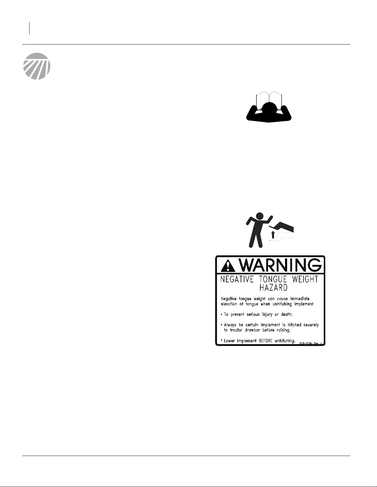
Be Familiar with Safety Decals
▲ Read and understand “Safety Reflectors and Decals”in
your Operator manual.
▲ Read all instructions noted on the decals.
03/24/2009 195-073M
Page 6
2 Electric Clutch Package Great Plains Manufacturing, Inc.
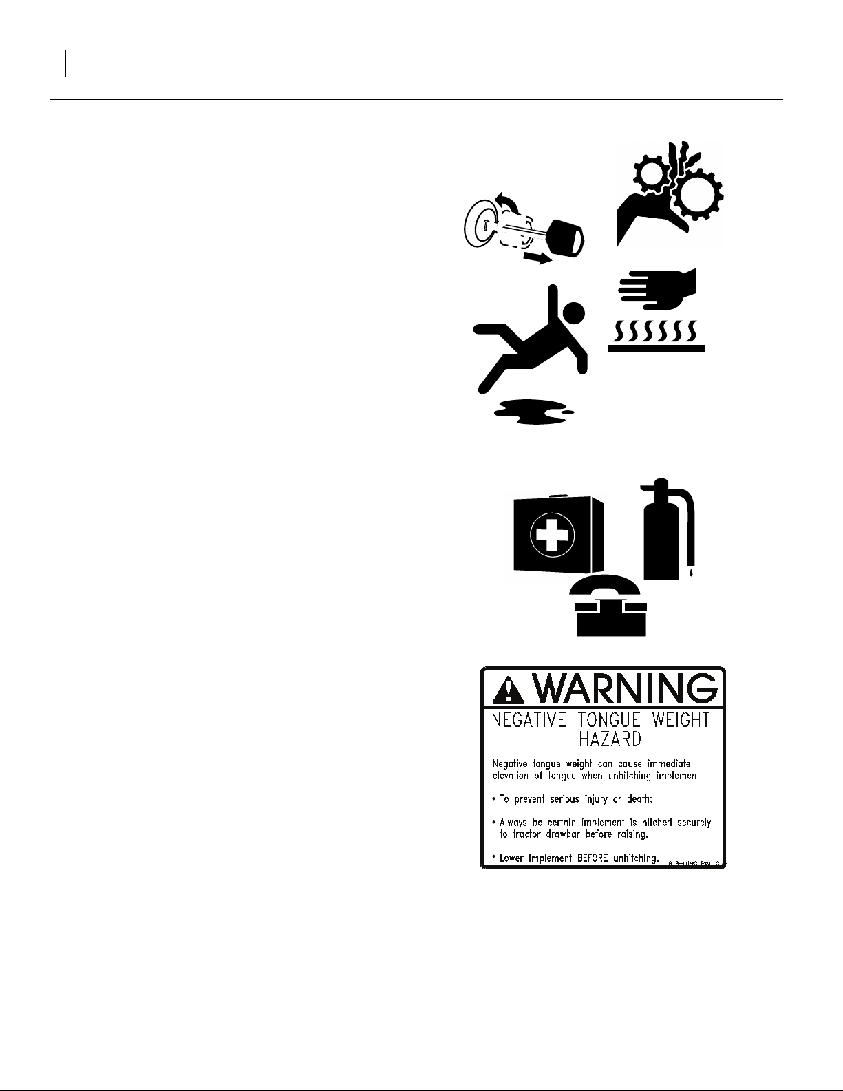
Practice Safe Maintenance
▲ Understand procedure before doing work. Use proper tools
and equipment. Refer to this manual for additional information.
▲ Work in a clean, dry area.
▲ Make sure all moving parts have stopped and all system
pressure is relieved.
▲ Inspect all parts. Make sure parts are in good condition and
installed properly.
▲ Remove buildup of grease, oil or debris.
▲ Remove all tools and unused parts from implement before
operation.
OFF
Prepare for Emergencies
▲ Be prepared if a fire starts.
▲ Keep a first aid kit and fire extinguisher handy.
▲ Keep emergency numbers for doctor, ambulance, hospital
and fire department near phone.
Safety At All Times
▲ Thoroughly read and understand the instructions in this
manual before operation. Read all instructions noted on the
safety decals.
▲ Be familiar with all implement functions.
▲ Operate machinery from the driver’s seat only.
▲ Do not leave implement unattended with tractor engine
running.
▲ Wear snug-fitting clothing to avoid entanglement with mov-
ing parts.
911
195-073M 03/24/2009
Page 7
Great Plains Manufacturing, Inc. 3
General Information
These packages replace the standard lift-actuated
mechanical clutches on each section with electric
clutches control both by a single drill lift switch and by
cab module section switches. This is an alternative way
to provide point row capability, where point row operations do not require raising the non-planting sections
These instructions explain how to install an Electric
Clutch Package, provided as one of four kits:
Kit Kit Description
195-075A 3S-40 ELEC CL PKG SML SDS-FERT
195-076A 2S-2600 ELEC CLUTCH PKG
195-077A 2S-26 ELEC CL PKG SML SDS-FERT
195-078A 3S-3000 ELECTRIC CLUTCH PKG
Note: These instructions do not cover the case of adding
electric clutches to a drill which has previously had
the Point Row option installed. In such an unlikely
case, please have the Great Plains dealer contact
the factory for further instructions.
Notations and Conventions
“Left” and “Right” are facing in the direction of machine travel. An orientation rose
in many figures shows the directions of
Left, Right, Front, Back, Up, Down.
Note: Many figures show fully exploded views. Remove
only specified parts.
A crucial point of information related to the preceding
topic. Read and follow the directions provided before
continuing, to ensure safety, avoidance of machine
damage, and to achieve desired field results.
Note: Useful information related to the preceding topic.
A glossary of abbreviations used in part descriptions is
available on page 98.
U
F
L
R
B
D
Each kit updates one drill. Kits are specific to the number
of drill sections, and on 2S-2600, whether or not the
Small Seeds and/or Fertilizer Options are also present:
Drill
Drill Model
2S-2600 s/n DD1152+
2S-2600HD
2S-2600 s/n DD1152+
2S-2600HD
2S-2600F s/n DD1152+
2S-2600HDF
3S-3000
3S-3000F
3S-3000HD
3S-3000HDF
4S-4000
4S-4000F
4S-4000HD
4S-4000HDF
Vintage
any
any
any
1996+, s/n S1563+
any
s/n YY1152+
any
Small
Seeds
No 195-076A
Ye s
n/a
any 195-078A
any 195-075A
Uses
Kit
195-077A
Call-Outs
1 9
-,
a z
-
11 61
to
101 138
to
Single-digit/letter callouts identify components in the currently referenced Figure or
Figures. These references are reused for different items from section to section.
Two-digit callouts in the range 11 to 61 reference new parts from the new parts lists
beginning on page 94. The descriptions
match those on the parts, bags or cartons,
and in your updated Parts Manual.
Three-digit callouts in the range 101 to 138
reference affected existing parts from the
table on page 97. The descriptions match
those in your Parts Manual. The narrative
and table indicate any re-use of the parts.
03/24/2009 195-073M
Page 8
4 Electric Clutch Package Great Plains Manufacturing, Inc.
Pre-Assembly Preparation
Before You Start
• If the drill is not an “HD” model, check (against the
table on page 3) the drill serial number and production
date to ensure it has existing parts compatible with the
kit. Electric clutch kits are not available for earlier drills.
• Inventory: make sure all parts are present. A complete
material list begins on page 94.
• Comprehension: review this manual make sure the
installers understand where each part or assembly is
installed, and what tools are required for the task.
Tools Required
• updated drill parts manual,
• tractor (installing cab control module requires access
to the tractor used in field operations with this drill),
• 23 foot or longer cable snake,
• scrap wire for tying springs in compression,
• basic hand tools, including:
- punch for driving out
5
-
⁄
in long-arm hex wrench.
32
1
⁄
in roll pins
4
Work Location
1. Move the drill to a location with:
• room to unfold it, and;
• adequate illumination.
Prepare Drill
Consult Operator Manual if any steps are unfamiliar.
2. Unfold the drill:
• Fully unfold a 2S drill.
• Partially unfold a 3S drill. Stop unfolding before
the right transfer drive jaws come into line with
the center section jaws, so that center shaft can
be removed, and the right hand shaft moved left.
3. Remove transport locks and lower the drill.
Lower the row units.
4. Put tractor in Park, and shut down.
Install Kit
Installation is described separately for each kit:
2-Section, main box only, 195-076A kitpage 5
2-Section, w/Option box(es), 195-077A kitpage 15
3S-3000, main box only, 195-078A kitpage 27
3S-3000, w/option box(es), 195-078A kitpage 42
3S-4000, main box only, 195-075A kitpage 61
3S-4000, w/option box(es), 195-075A kitpage 74
Note: This manual has you update one drill section at a
time, to prevent part confusion. Parts are different
for each drill section (bolt lengths in particular).
If you dismantle all removed hardware at once,
there is risk of re-installing incorrect parts from
another drill section.
195-073M 03/24/2009
Page 9
Great Plains Manufacturing, Inc. Update 2S-2600 Left Hand Drive 5
2S-2600 Main Box Only Installation
This section describes installation of kit 195-076A for:
• 2S-2600 s/n DD1152+ drills with only a main seed
box, and no Small Seeds or Fertilizer options, or;
• 2S-2600HD drills with only a main seed box, and
no Small Seeds or Fertilizer options.
Update 2S-2600 Left Hand Drive
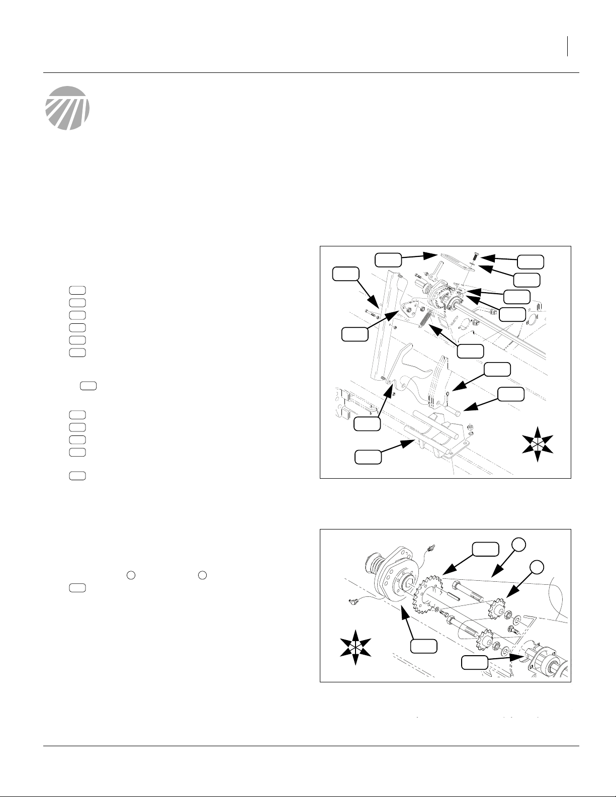
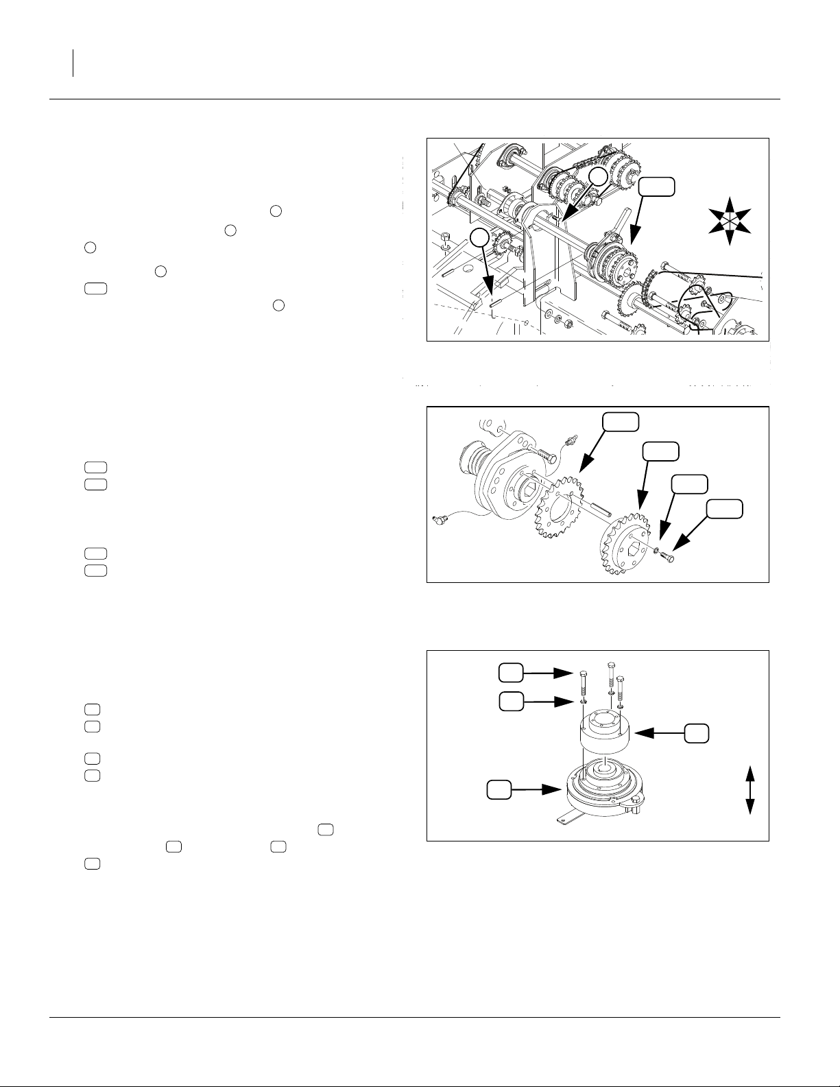
Remove 2S-2600 LH Linkage
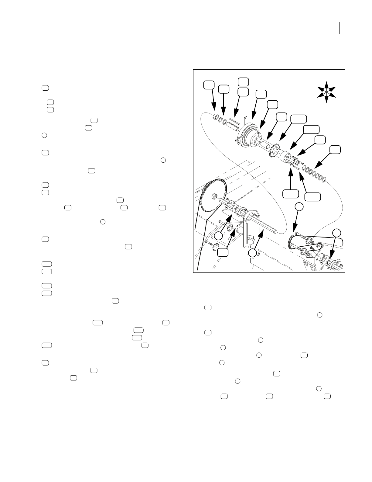
Refer to Figure 1
5. Remove individually or as an assembly:
106
195-130H CLUTCH SHUTOFF LINK, 00 SERIES
108
195-144D CLUTCH SHUTOFF CAM, 00 SERIES
118
195-254D CLUTCH PULL TAB
132
805-083C PIN CLEVIS 3/4 X 1 1/2
133
805-109C PIN COTTER 1/8 X 1 1/4 PLT
134
807-072C SPRING EXT 1 1/16 ODX.120WX5.5
These parts are not re-used.
Note: This part may be removed or left in place:
107
195-131H SUBFRM CLUTCH BRKT,SOLID STAND
6. Remove two sets:
124
802-079C HHCS 3/8-16X1 1/4 GR5
129
804-011C WASHER FLAT 3/8 USS PLT
130
804-013C WASHER LOCK SPRING 3/8 PLT
127
803-014C NUT HEX 3/8-16 PLT
and remove the:
101
152-263D CLUTCH ENGAGE TAB
These parts are not re-used.
For other kits, see:
2S-2600, w/option box(es), 195-077A kitpage 15
3S-3000, main box only, 195-078A kitpage 27
3S-3000, w/option box(es), 195-078A kitpage 42
3S-4000, main box only, 195-075A kitpage 61
3S-4000, w/option box(es), 195-075A kitpage 74
101
106
124
129
130
127
118
134
133
132
108
R
107
Figure 1: 2S-2600:
Remove LH Linkage
F
U
B
L
D
17253
Remove 2S-2600 LH Shaft and Clutch
Dismount Clutch Output Chain
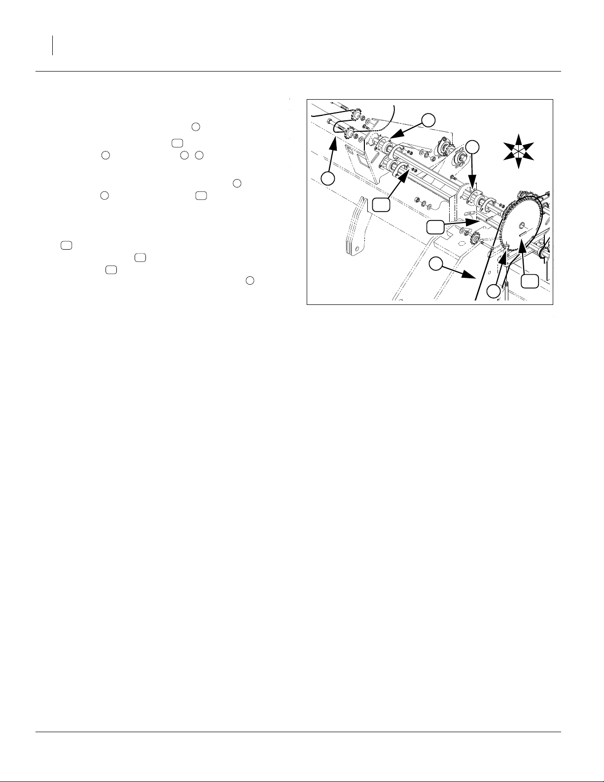
Refer to Figure 2
7. Loosen idler and lift chain off of sprocket:
136
808-240C SPKT 40A23X1.813-1.818 BR/6HOL
Do not completely remove the chain.
i n
136
n
i
U
R
B
102
F
L
115
D
Figure 2: 2S-2600:
Dismount LH Clutch Chain
03/24/2009 195-073M
21627
Page 10
6 Electric Clutch Package Great Plains Manufacturing, Inc.
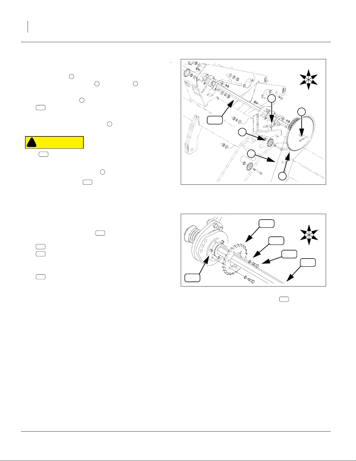
Dismount Ground Drive Chain & Sprocket
R
F
U
B
L
D
e
Refer to Figure 3
8. Loosen idler in gauge wheel assembly.
Lift ground drive chain off sprocket .
Do not completely remove the chain.
9. Drive the roll pin out of the left end of shaft:
115
195-189D POWER SHAFT 7/8 HEX LH
This pin is not re-used.
10. Remove and save sprocket .
Remove Drive Shaft
CAUTION
!
115
Shaft moves, under spring tension, about
the right as the next pin is removed.
a
c k
e
k
1
⁄
in (13mm) to
2
f
115
a
c
11. Drive out the mid roll pin . Pin is not re-used.
12. Remove the shaft from the drill (slide out to
right, with the clutch still mounted).
115
f
Disassemble 2S-2600 LH Clutch
Refer to Figure 4
13. At the clutch assembly , remove and save three
sets:
123
802-004C HHCS 1/4-20X3/4 GR5
128
804-006C WASHER LOCK SPRING 1/4 PLT
14. The sprocket may still be held by pins. Remove and
save the sprocket:
136
808-240C SPKT 40A23X1.813-1.818 BR/6HOL
Any roll pins present, the shaft, and the balance of
the clutch assembly are not re-used.
102
102
Figure 3: 2S-2600:
Release LH Power Shaft
136
128
Figure 4: 2S-2600:
Disassemble LH Clutch
k
123
102
R
F
21627
U
B
L
D
115
28106
195-073M 03/24/2009
Page 11
Great Plains Manufacturing, Inc. Update 2S-2600 Left Hand Drive 7
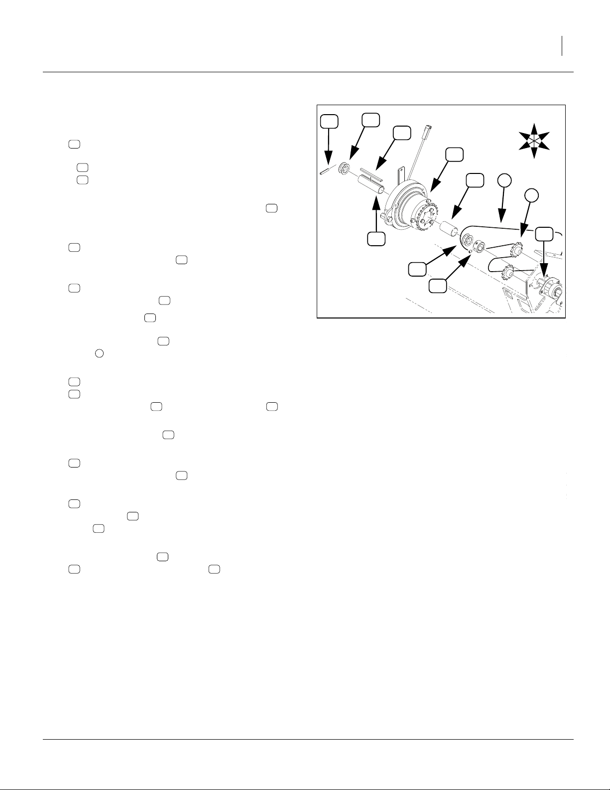
Pre-Assemble 2S-2600 LH Clutch
Refer to Figure 5
15. Select one each new:
54
823-231C OGURA CLUTCH
22
195-347D ELECTRIC CLUTCH ADAPTOR
and three sets new:
34
802-684C HHCS M8X1.25X55 GR8.8
48
804-157C WASHER SPRING LOCK M8 PLT
Place the tab end of down on a work surface.
16. Secure the large end of the 195-347D adaptor to
the Ogura clutch with the bolts and lock wash-
48
ers . Torque to specifications (see page 93).
Note: Note that the 195-347D adaptor has alternating
smooth and tapped (threaded)
54
54 34
22
1
⁄
4
22
in holes.
17. Select the saved:
136
808-240C SPKT 40A23X1.813-1.818 BR/6HOL
and three sets saved:
123
802-004C HHCS 1/4-20X3/4 GR5
128
804-006C WASHER LOCK SPRING 1/4 PLT
and three new
49
805-026C PIN ROLL 1/4 X 3/4 PLT
18. Place the sprocket on the clutch and align
136
the holes. Loosely insert the bolts and washers
128
in the threaded holes. Drive the roll pins into
22
123
49
the smooth holes. Tighten bolts to specification.
123
128
34
48
54
Figure 5: 2S-2600
Assemble LH Clutch
49
136
22
U
D
28107
Prepare New 2S-2600 LH Power Shaft
Refer to Figure 6
19. Select one each new:
21
195-346D SHAFT 7/8 HEX 32.44 LG
50
805-180C PIN ROLL 1/4 X 1 1/2 LG PLT
20. Drive pin into the inner hole of the shaft .
50 21
21
Figure 6: 2S-2600:
Pin New LH Shaft
50
28094
03/24/2009 195-073M
Page 12
8 Electric Clutch Package Great Plains Manufacturing, Inc.
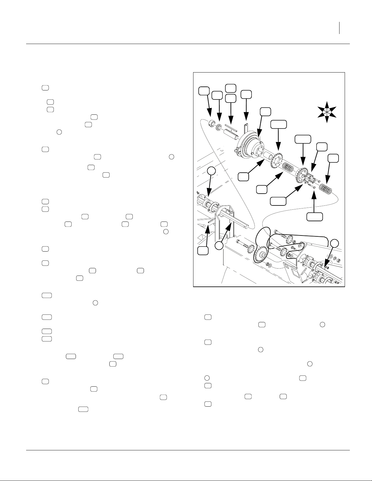
Install New 2S-2600 LH Power Shaft
Refer to Figure 7 (which, for clarity, is a fully exploded view)
21. From drill left, insert shaft into the existing flanged
bearings .
22. Select the saved ground drive sprocket . Place the
sprocket onto the new shaft , with the raised
hub of the sprocket to drill right (towards bearings).
23. Select one new:
50
805-180C PIN ROLL 1/4 X 1 1/2 LG PLT
24. Drive the roll pin into the hole at the left end of
new shaft , securing the sprocket.
Note: Do not remount the ground drive chain at this
time.
b
k21
50
21
21
k
c
b
21
50
c
Figure 7: 2S-2600:
Install LH Power Shaft
U
R
B
b
F
L
D
50
k
28056
195-073M 03/24/2009
Page 13
Great Plains Manufacturing, Inc. Update 2S-2600 Left Hand Drive 9
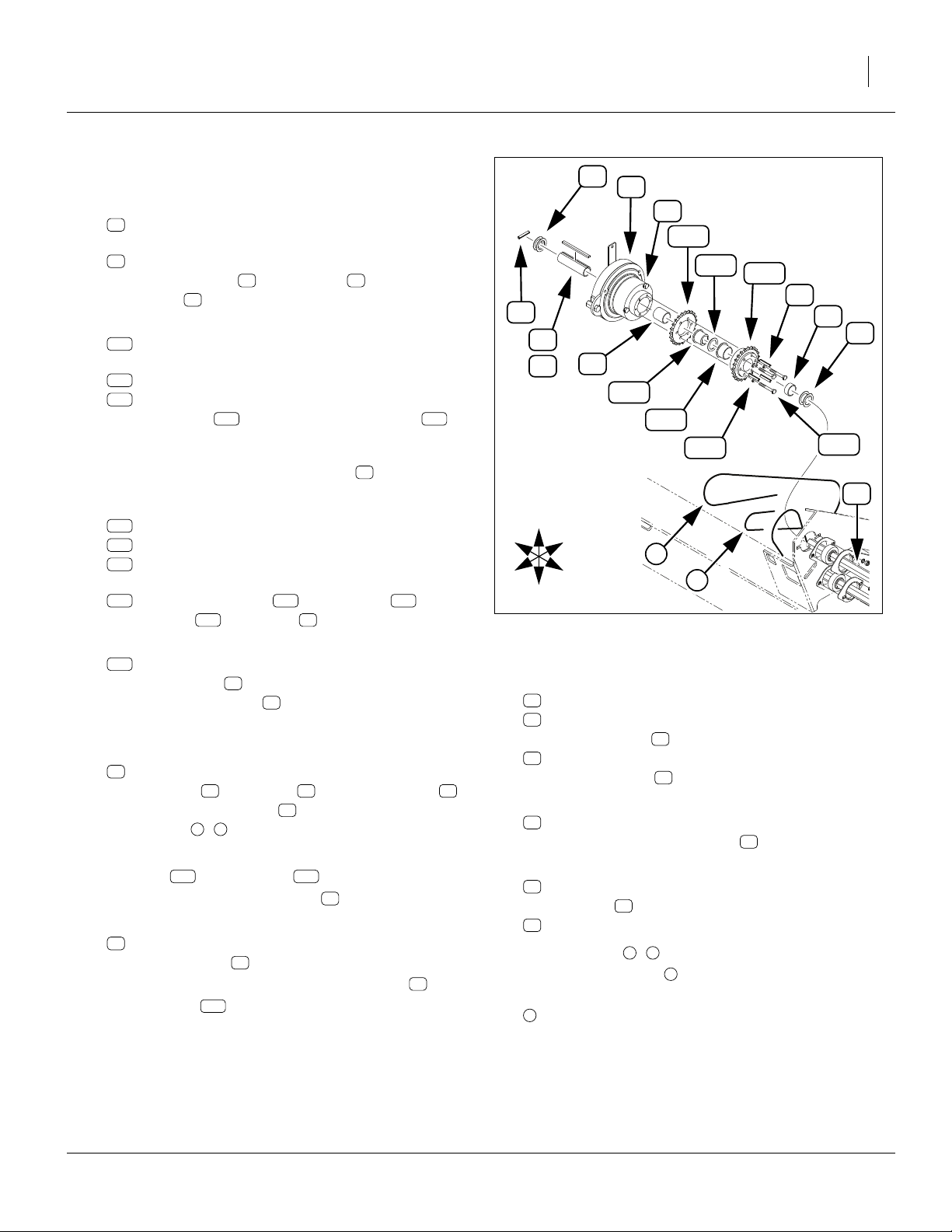
Install 2S-2600 LH Clutch
Refer to Figure 8
25. Select one new:
27
402-025S LOCK COLLAR, 7/8 HEX W/ SET SC
which, if not pre-assembled, consists of:
60
1 402-058D COLLAR LOCK 7/8 HEX and
61
2 801-035C SCREW SET 5/16-18 SKT KP X 3/8
26. Adjust the set screws to clear the collar hex hole,
and place the collar onto the new drive shaft .
Do not tighten the set screws at this time.
27. Select two new:
46
804-061C WASHER MACH 1.50 X 1.00 X 18GA
Place them on the shaft .
28. Select one new:
23
195-348D CLUTCH SPACER TUBE
Place it on the shaft .
29. Select the clutch assembled at step 18. With the
sprocketed end toward the left (toward bearings),
place it on the shaft , and into the Drive Type
n
chain .
30. Select one each new:
26
196-877D BUSHING 1 1/8 ODX7/8 HEX BORE
58
839-956C KEY 1/4 X 3/16 X 3.80
Insert the bushing in the clutch assembly .
31. Align the keyways of the bushing and the Ogura
clutch. Insert the key .
32. Select two new:
46
804-061C WASHER MACH 1.50 X 1.00 X 18GA
Place them on the shaft .
33. Select one new:
50
805-180C PIN ROLL 1/4 X 1 1/2 LG PLT
Drive the pin into the hole at the right end of the
21
shaft , to secure all the components just installed
on the shaft.
34. Slide the lock collar right until it and the washers
46 54
contact the clutch assembly . Secure the set
screws.
54
50
21
21
21
26 54
58
21
27
21
50
46
58
54
23
26
46
27
Figure 8: 2S-2600
Install LH Clutch
U
R
F
B
L
D
n
i
21
28056
03/24/2009 195-073M
Page 14
10 Electric Clutch Package Great Plains Manufacturing, Inc.
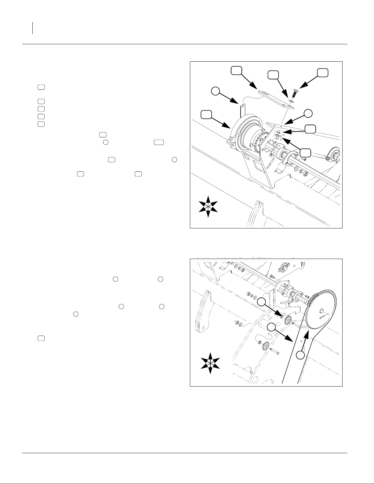
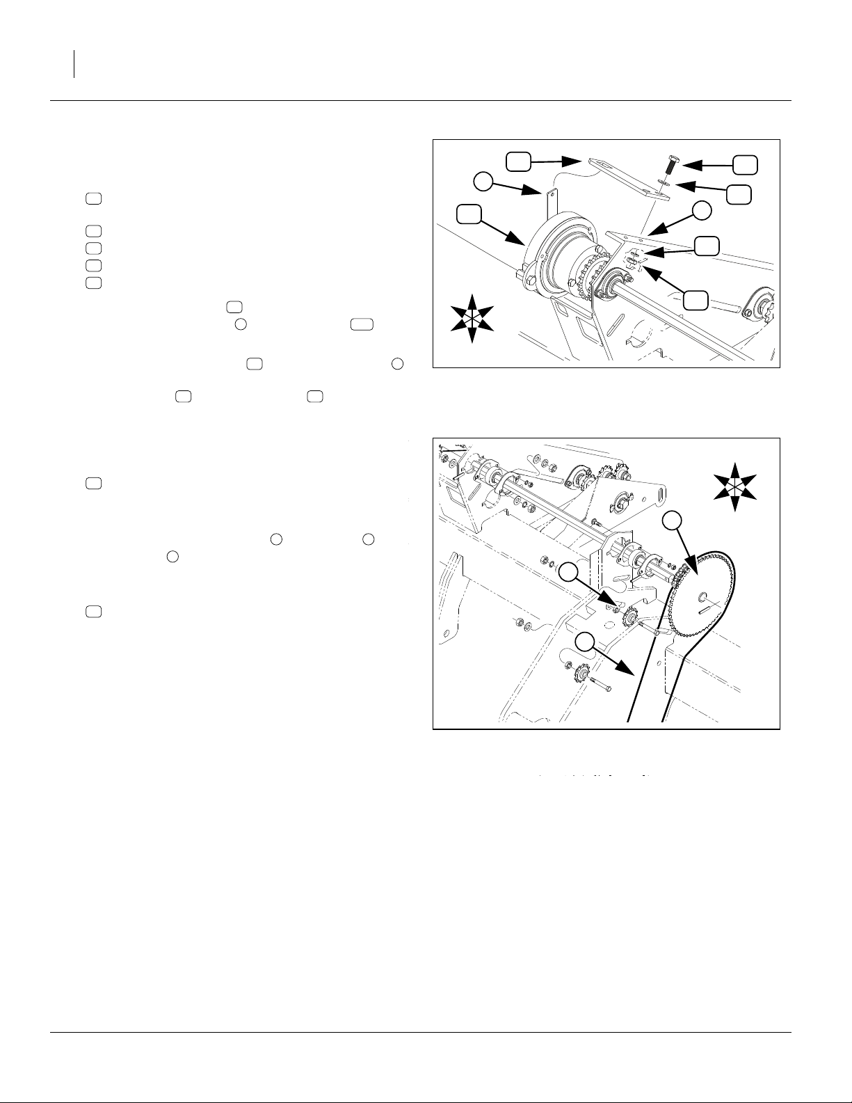
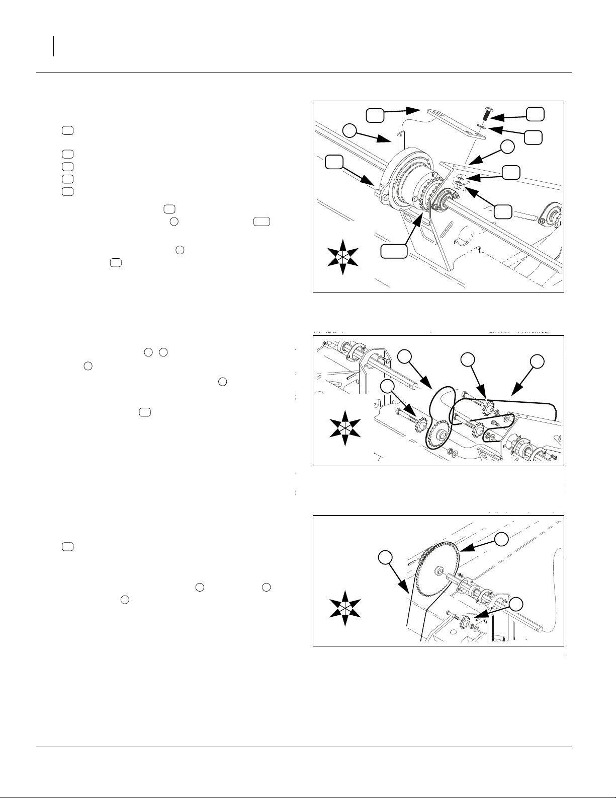
Install 2S-2600 LH Torque Tab
Refer to Figure 9
35. Select one new:
20
195-345D CLUTCH TORQUE ARM TAB
and two sets new:
30
802-079C HHCS 3/8-16X1 1/4 GR5
41
804-011C WASHER FLAT 3/8 USS PLT
42
804-013C WASHER LOCK SPRING 3/8 PLT
36
803-014C NUT HEX 3/8-16 PLT
36. Loosely mount the tab at the same Drive Type
bracket weldment holes used by the tab
removed at step 6.
37. Rotate the clutch housing until the torque arm
is nearly vertical. Route it through the large hole in
the torque tab . Tighten the bolts to torque
specifications.
20
20
h
54 t
30
101
54
20
41
30
t
h
42
36
U
R
B
2S-2600 LH Closeout
Refer to Figure 8 on page 9
38. Re-mount Drive Type chain . Engage idler for
1
⁄
in (13mm) slack in longest chain span.
2
Refer to Figure 10
39. Re-mount gauge wheel chain on sprocket .
Engage idler for 1in (2.7cm) slack in longest chain
span.
40. Select one new (not shown):
55
833-088C OGURA CLUTCH JUMPER HARNESS
Connect the jumper to the clutch cable.
a
n i
c k
F
L
D
Figure 9: 2S-2600:
Install Torque Arm Tab
28082
a
c
U
R
F
B
L
k
D
Figure 10: 2S-2600:
Re-Install LH Gauge Wheel Chain
28056
195-073M 03/24/2009
Page 15
Great Plains Manufacturing, Inc. Update 2S-2600 Right Hand Drive 11
Update 2S-2600 Right Hand Drive
Remove 2S-2600 RH Linkage
Refer to Figure 11 (which depicts the LH linkage, but the
parts to be removed, and their general arrangement, are
identical on the RH side)
41. Remove individually or as an assembly:
106
195-130H
108
195-144D CLUTCH SHUTOFF CAM, 00 SERIES
118
195-254D CLUTCH PULL TAB
132
805-083C PIN CLEVIS 3/4 X 1 1/2
133
805-109C PIN COTTER 1/8 X 1 1/4 PLT
134
807-072C
These parts are not re-used.
Note: This part may be removed or left in place:
107
195-131H SUBFRM CLUTCH BRKT,SOLID STAND
42. Remove two sets:
124
802-079C HHCS 3/8-16X1 1/4 GR5
129
804-011C WASHER FLAT 3/8 USS PLT
130
804-013C WASHER LOCK SPRING 3/8 PLT
127
803-014C NUT HEX 3/8-16 PLT
and remove the:
101
152-263D CLUTCH ENGAGE TAB
These parts are not re-used.
CLUTCH SHUTOFF LINK, 00 SERIES
SPRING EXT 1 1/16 ODX.120WX5.5
101
106
118
134
133
108
107
Figure 11: 2S-2600:
Remove RH Linkage
129
130
127
132
R
F
124
U
B
L
D
17253
Release 2S-2600 RH Drive Shaft
Remove 2S-2600 RH Chains and Input Sprocket
Refer to Figure 12
43. At the Drive Type bracket, loosen idler and lift
Drive Type drive chain off clutch output sprocket
136
. Do not completely remove the chain.
44. Loosen ground drive idler and lift ground drive
c k
chain off sprocket . Do not completely remove
the chain.
45. Drive right end roll pin out of input shaft . Pin is
not re-used.
46. Remove and save the sprocket .
n
a
r d
k
i
R
U
B
k
r
F
L
D
d
n
i
a
c
RH Chains and Input Sprocket
136
Figure 12: 2S-2600:
21629
03/24/2009 195-073M
Page 16
12 Electric Clutch Package Great Plains Manufacturing, Inc.
Remove 2S-2600 RH Clutch
Refer to Figure 13
CAUTION
!
d
Shaft may move, under spring tension, about
to drill right as the next pin is removed.
1
⁄
in (13mm)
2
d
102
R
F
U
B
L
D
47. Drive out the mid roll pin . This pin is not re-used.
48. Move the shaft to the right. Remove the:
102
176-042S JAW CLUTCH CW EXT 7/8 HEX
from the shaft . Leave the shaft in the drill.
d
d
f
Disassemble 2S-2600 RH Clutch
Refer to Figure 14
49. From the clutch assembly , remove and save
three sets:
126
802-551C HHCS 1/4-20X2 1/4 GR5
128
804-006C WASHER LOCK SPRING 1/4 PLT
50. The adaptor and sprocket may still be held
on by roll pins. Remove and save the adaptor and
sprocket:
111
195-170D CLUTCH ADAPTOR 7/8 HEX BORE
136
808-240C SPKT 40A23X1.813-1.818 BR/6HOL
Any roll pins present, and the balance of the clutch
assembly , are not re-used.
111 136
102
102
102
f
Figure 13: 2S-2600:
RH Clutch Dismount
136
Figure 14: 2S-2600:
Disassemble RH Clutch
21629
111
128
126
28108
102
Pre-Assemble 2S-2600 RH Clutch
Refer to Figure 15
51. Select one each new:
54
823-231C OGURA CLUTCH
22
195-347D ELECTRIC CLUTCH ADAPTOR
and three sets new:
34
802-684C HHCS M8X1.25X55 GR8.8
48
804-157C WASHER SPRING LOCK M8 PLT
Place the clutch on a work surface, tab end down.
52. Secure the large end of the 195-347D to the
Ogura clutch with the bolts and lock washers
48
. Torque to specifications (see page 93).
195-073M 03/24/2009
54 34
22
34
48
54
Figure 15: 2S-2600:
Pre-assemble RH Clutch
22
U
D
28144
Page 17
Great Plains Manufacturing, Inc. Update 2S-2600 Right Hand Drive 13
Install 2S-2600 RH Clutch
Refer to Figure 16
53. Select one new:
27
402-025S LOCK COLLAR, 7/8 HEX W/ SET SC
which, if not pre-assembled, consists of:
60
1 402-058D COLLAR LOCK 7/8 HEX and
61
2 801-035C SCREW SET 5/16-18 SKT KP X 3/8
54. Adjust set screws to clear the collar hex hole.
Place the collar on the left end of the input shaft
d
. Do not tighten the set screws at this time.
61
27
55. Select two new:
46
804-061C WASHER MACH 1.50 X 1.00 X 18GA
Place them on the left end of the input shaft .
56. Select the clutch assembled at step 52, and one
54
d
each new:
26
196-877D BUSHING 1 1/8 ODX7/8 HEX BORE
58
839-956C KEY 1/4 X 3/16 X 3.80
Place bushing inside clutch . Align keyways of
bushing and Ogura clutch . Insert key . With
26 54 58
54
tab end to drill right, place the clutch assembly on left
end of the input shaft .
d
57. Select one new:
23
195-348D CLUTCH SPACER TUBE
Insert it in the clutch assembly .
22
58. Select one each saved:
136
808-240C SPKT 40A23X1.813-1.818 BR/6HOL
111
195-170D CLUTCH ADAPTOR 7/8 HEX BORE
three sets saved:
126
802-551C HHCS 1/4-20X2 1/4 GR5
128
804-006C WASHER LOCK SPRING 1/4 PLT
Note: Note that the 195-347D has alternating smooth
and tapped (threaded)
59. Place the sprocket on the clutch adaptor and
136
align the holes. Place the adaptor on the
sprocket. Loosely insert the bolts and washers
128
in the threaded holes of adaptor .
22
1
⁄
in holes.
4
22
111
126
22
60. Select three new:
50
805-180C PIN ROLL 1/4 X 1 1/2 LG PLT
Drive the roll pins into the smooth holes of the
195-347D . Tighten bolts to specification. Re-seat
22
49
roll pins as required.
27
46
58
26
54
22
23
136
111
128
n
b
50
61. Select seven (7) new:
46
804-061C WASHER MACH 1.50 X 1.00 X 18GA
Place them on the driven acremeter shaft .
62. Select one new:
50
805-180C PIN ROLL 1/4 X 1 1/2 LG PLT
Shift the input shaft to drill left, into Drive Type
n
chain , until the mid roll pin hole appears to the left
of the right bearing . Drive the pin into the input
d
shaft mid hole.
63. Shift the clutch assembly to drill left, into Drive
Type chain , until the left end of clutch has captured the right end of the acremeter shaft . Slide
27 46 54
collar and washers left against clutch .
Secure set screws.
d
Figure 16: 2S-2600:
Install RH Clutch
d
b50
54
n
R
F
126
U
B
L
D
50
46
s
28147
s
s
03/24/2009 195-073M
Page 18
14 Electric Clutch Package Great Plains Manufacturing, Inc.
Install 2S-2600 RH Torque Tab
h
42
30
41
Refer to Figure 17
64. Select one new:
20
195-345D CLUTCH TORQUE ARM TAB
and two sets new:
30
802-079C HHCS 3/8-16X1 1/4 GR5
41
804-011C WASHER FLAT 3/8 USS PLT
42
804-013C WASHER LOCK SPRING 3/8 PLT
36
803-014C NUT HEX 3/8-16 PLT
20
t
54
36
65. Loosely mount the tab at the same Drive Type
bracket weldment holes used by the tab
removed at step 42.
66. Rotate the clutch until the torque arm is in the
large hole in the torque tab .
67. Tighten tab bolts to torque specifications.
20
h
54 t
20
30
101
R
F
U
D
B
136
L
Figure 17: 2S-2600:
Install RH Torque Arm Tab
28148
2S-2600 RH Closeout
Refer to Figure 17 and Figure 18
68. Re-mount Drive Type chain .
69. Select one new (not shown):
55
833-088C OGURA CLUTCH JUMPER HARNESS
Connect the jumper to the clutch cable.
70. Engage chain idler for
est chain span.
Refer to Figure 19
71. Re-mount gauge wheel chain on sprocket .
Engage idler for 1in (2.7cm) slack in longest chain
span.
i
a
n
1
⁄
in (13mm) slack in long-
2
c k
Install 2S-2600 Electronics
Continue at “2S Electrical Installation” on page 25.
These steps are common to both 2S-2600 and 2S2600F/SGS models.
R
F
R
F
n
U
B
L
D
Figure 18: 2S-2600:
Remount RH Drive Type Chain
c
U
B
L
D
i
28057
k
a
Figure 19: 2S-2600:
Remount RH Ground Drive Chain
195-073M 03/24/2009
28057
Page 19
Great Plains Manufacturing, Inc. Update 2S-2600F/SGS Left Hand Drive 15
2S-2600F & 2S-2600 Small Seeds Installation
This section describes installation of kit 195-077A for:
• 2S-2600 s/n DD1152+ drills with Small Seeds,
• 2S-2600F s/n DD1152+ drills,
• 2S-2600HD drills with Small Seeds, or;
• 2S-2600HDF drills,
…referred to as “2S-2600F/SGS” in this section.
Update 2S-2600F/SGS Left Hand Drive
Remove 2S-2600F/SGS LH Linkage
Steps 1-4 are on page 4.
Refer to Figure 20 (which depicts a standard 2S-2600 linkages, but the parts removed for 2600F and SGS are the same)
5. Remove individually or as an assembly:
106
195-130H CLUTCH SHUTOFF LINK, 00 SERIES
108
195-144D CLUTCH SHUTOFF CAM, 00 SERIES
118
195-254D CLUTCH PULL TAB
132
805-083C PIN CLEVIS 3/4 X 1 1/2
133
805-109C PIN COTTER 1/8 X 1 1/4 PLT
134
807-072C SPRING EXT 1 1/16 ODX.120WX5.5
These parts are not re-used.
Note: This part may be removed or left in place:
107
195-131H SUBFRM CLUTCH BRKT,SOLID STAND
6. Remove two sets:
124
802-079C HHCS 3/8-16X1 1/4 GR5
129
804-011C WASHER FLAT 3/8 USS PLT
130
804-013C WASHER LOCK SPRING 3/8 PLT
127
803-014C NUT HEX 3/8-16 PLT
and remove the:
101
152-263D CLUTCH ENGAGE TAB
These parts are not re-used.
For other kits, see:
2S-2600, main box only, 195-076A kitpage 5
3S-3000, main box only, 195-078A kitpage 27
3S-3000, w/option box(es), 195-078A kitpage 42
3S-4000, main box only, 195-075A kitpage 61
3S-4000, w/option box(es), 195-075A kitpage 74
101
106
124
129
130
127
118
134
133
132
108
R
107
Figure 20: 2S-2600F/SGS:
Remove LH Linkage
F
U
B
L
D
17253
03/24/2009 195-073M
Page 20

16 Electric Clutch Package Great Plains Manufacturing, Inc.
Remove 2S-2600F/SGS LH Shaft and Clutch
Dismount Clutch Output Chains
Refer to Figure 21
7. Loosen Drive Type idler and Fertilizer/SGS jackshaft idler . Lift Drive Type chain and Fertilizer/
SGS jackshaft chain off the sprockets on:
113
195-187K 3S-3000F LH WING CLUTCH ASSY
Do not completely remove the chains.
v n
i
u
n
113
U
i
R
F
B
L
D
v
u
r
Release 2S-2600F/SGS LH Power Shaft
Refer to Figure 22
8. Loosen idler in gauge wheel assembly.
Lift ground drive chain off sprocket .
Do not completely remove the chain.
9. Drive the roll pin out of the left end of shaft:
115
195-189D POWER SHAFT 7/8 HEX LH
This pin is not re-used.
10. Remove and save sprocket .
a
c k
e
k
Remove 2S-2600F/SGS LH Power Shaft
CAUTION
!
113
1
⁄
in (13mm) to
2
115
Shaft moves, under spring tension, about
the right as the next pin is removed.
11. Drive out the middle roll pin . Pin is not re-used.
12. Slide the shaft (with clutch still mounted)
out of the drill, to the right.
13. Remove the clutch for disassembly:
113
195-187K 3S-3000F LH WING CLUTCH ASSY
The shaft is not re-used.
115
f
Figure 21: 2S-2600F/SGS:
Remove LH Clutch Chains
f
115
a
c
Figure 22: 2S-2600F/SGS:
Release LH Power Shaft
21628
U
R
F
B
L
D
e
k
21628
195-073M 03/24/2009
Page 21
Great Plains Manufacturing, Inc. Update 2S-2600F/SGS Left Hand Drive 17
Disassemble 2S-2600F/SGS LH Clutch
Refer to Figure 23
14. Remove and save three sets:
125
802-152C HHCS 1/4-20X2 GR5
128
804-006C WASHER LOCK SPRING 1/4 PLT
The assembly is usually still held together by roll
pins.
15. Pry both sprockets off. Remove and save:
109
195-160H SPKT CLUTCH 40B23T RND BORE
136
808-240C SPKT 40A23X1.813-1.818 BR/6HOL
The following parts usually remain in the adaptor-
sprocket and do not need to be removed.
138
103
116
The remaining parts are not re-used.
136
817-111C BSHG FLG 1.26IDX1.41ODX.87L
176-065D CLUTCH FRICTION WASHER
195-222D BRG 7/8 HEX ID X 1.254 OD
136
116
113
103
138
Figure 23: 2S-2600F/SGS:
Disassemble LH Clutch
113
109
128
125
16465
Pre-Assemble 2S-2600F/SGS LH Clutch
Refer to Figure 24
16. Select one each new:
54
823-231C OGURA CLUTCH
22
195-347D ELECTRIC CLUTCH ADAPTOR
and three sets new:
34
802-684C HHCS M8X1.25X55 GR8.8
48
804-157C WASHER SPRING LOCK M8 PLT
Set the clutch assembly on a work surface, with the
torque arm end of the Ogura clutch down.
17. Secure the large end of the 195-347D adaptor to
the Ogura clutch with the bolts and lock wash-
48
ers . Torque to specifications (see page 93).
54 34
22
34
48
54
Figure 24: 2S-2600F/SGS:
Pre-assemble LH Clutch
22
U
D
28144
Prepare New 2S-2600F/SGS LH Power Shaft
Refer to Figure 25
18. Select one each new:
21
195-346D SHAFT 7/8 HEX 32.44 LG
50
805-180C PIN ROLL 1/4 X 1 1/2 LG PLT
19. Drive the pin into the inner hole of the shaft .
03/24/2009 195-073M
50 21
21
Figure 25: 2S-2600F/SGS:
Pin New Shaft
50
28094
Page 22
18 Electric Clutch Package Great Plains Manufacturing, Inc.
Install New 2S-2600F/SGS LH Power Shaft
Refer to Figure 26 (which, for clarity, is a fully exploded
view, but omits the option box chain )
20. From drill left, insert shaft into the existing flanged
bearings and the chains , in the Drive Type
bracket.
21. Select the saved ground drive sprocket . Place
sprocket onto the new shaft , with the raised
hub of the sprocket to drill right (towards the bearings).
22. Select one new:
50
805-180C PIN ROLL 1/4 X 1 1/2 LG PLT
Drive the roll pin into the hole at the left end of
new shaft , securing the sprocket.
Note: Do not re-mount the gauge wheel chain until
step 38. This leaves the new shaft free to spin for
ease of installing additional components.
b n u
k21
50
21
u
21
k
c
n
21
Figure 26: 2S-2600F/SGS:
Install LH Power Shaft
b
50
c
U
R
b
F
B
L
D
50
k
28073
195-073M 03/24/2009
Page 23
Great Plains Manufacturing, Inc. Update 2S-2600F/SGS Left Hand Drive 19
Install 2S-2600F/SGS LH Clutch
Refer to Figure 27
23. Select two new:
46
804-061C WASHER MACH 1.50 X 1.00 X 18GA
and one new:
24
195-349D WING FERT CLUTCH OUTER SPCR TB
Place the washers on the shaft , followed by
the spacer .
24
46 21
24. Select one saved:
109
195-160H SPKT CLUTCH 40B23T RND BORE
and three sets saved:
125
802-152C HHCS 1/4-20X2 GR5
128
804-006C WASHER LOCK SPRING 1/4 PLT
Insert the bolts through the lock washers
125 128
and into every other hole in the sprocket. Insert from
the side with the smaller raised hub. Place the
sprocket, bolt face to left, onto shaft .
21
If the following parts are not present, re-insert them:
138
817-111C BSHG FLG 1.26IDX1.41ODX.87L
103
176-065D CLUTCH FRICTION WASHER
116
195-222D BRG 7/8 HEX ID X 1.254 OD
With any flanged ends to right, place the bushing
138 103 116
, the friction washer , the bearing and
the sprocket onto shaft .
136
21
25. Select one each saved:
136
808-240C
26. Select the clutch assembled at step 17. Note that
the 195-347D adaptor has alternating smooth
and tapped (threaded)
SPKT 40A23X1.813-1.818 BR/6HOL
54
22
1
⁄
in holes.
4
27. Select one new:
25
195-350D WING FERT CLUTCH INNER SPCR TB
Place spacer onto shaft . Place the clutch
over the spacer, adaptor end to left, and inside
both chains , .
25 21 54
22
n u
28. Loosely secure the two sprockets to the clutch using
22
1
⁄
in threaded
4
the bolts and washers at the
125 128
holes of the 195-347D adaptor .
29. Select three sets new:
50
805-180C PIN ROLL 1/4 X 1 1/2 LG PLT
Drive the roll pins into the sprockets and the
smooth
1
⁄
in holes of the 195-347D adaptor .
4
Tighten bolts to specification. Re-seat roll pins
50
22
125
as needed.
50
58
26
U
R
F
D
30. Select one each new:
26
58
Insert the bushing into the right end of the clutch
54
then insert the key .
31. Select two new:
46
Place the washers on the shaft .
32. Select one new:
50
Drive the pin into the right end hole of the shaft
21
33. Route chains ( , ) over the sprockets. Adjust idler
for Drive Type chain to
est chain span. Adjust idler for option jackshaft chain
u
46
54
22
136
103
109
50
24
46
25
116
138
128
125
21
B
n
L
Figure 27: 2S-2600F/SGS:
Install LH Clutch
196-877D BUSHING 1 1/8 ODX7/8 HEX BORE
839-956C KEY 1/4 X 3/16 X 3.80
. Align the keyways of the bushing and clutch,
804-061C WASHER MACH 1.50 X 1.00 X 18GA
805-180C PIN ROLL 1/4 X 1 1/2 LG PLT
50
, outside the washers.
n u
1
to
⁄
in (6mm) slack in longest chain span.
4
26
58
u
28101
21
1
n
⁄
in (13mm) slack in long-
2
03/24/2009 195-073M
Page 24
20 Electric Clutch Package Great Plains Manufacturing, Inc.
Install 2S-2600F/SGS LH Torque Tab
Refer to Figure 28
34. Select one new:
20
195-345D CLUTCH TORQUE ARM TAB
and two sets new:
30
802-079C HHCS 3/8-16X1 1/4 GR5
41
804-011C WASHER FLAT 3/8 USS PLT
42
804-013C WASHER LOCK SPRING 3/8 PLT
36
803-014C NUT HEX 3/8-16 PLT
35. Loosely mount the tab at the same Drive Type
bracket weldment holes used by the tab
removed at step 6.
36. Rotate the clutch housing until the torque arm
is nearly vertical. Route it through the large hole in
the torque tab . Tighten the bolts to torque
specifications.
20
20
h
54 t
30
101
54
U
R
F
D
20
30
t
41
h
42
B
36
L
Figure 28: 2S-2600F/SGS:
Install LH Torque Arm Tab
28100
2S-2600F/SGS LH Closeout
37. Select one new (not shown):
55
833-088C OGURA CLUTCH JUMPER HARNESS
Connect the jumper to the clutch cable.
Refer to Figure 29
38. Re-mount gauge wheel chain on sprocket .
Engage idler for 1in (2.7cm) slack in longest chain
span.
39. Select one new (not shown):
55
833-088C OGURA CLUTCH JUMPER HARNESS
Connect the jumper to the clutch cable.
a
c k
R
F
k
a
c
Figure 29: 2S-2600F/SGS:
Re-Install LH Gauge Wheel Chain
U
B
L
D
28056
195-073M 03/24/2009
Page 25
Great Plains Manufacturing, Inc. Update 2S-2600F/SGS Right Hand Drive 21
Update 2S-2600F/SGS Right Hand
130
127
132
R
F
124
129
U
B
L
D
17253
Drive
Remove 2S-2600F/SGS RH Linkage
Refer to Figure 30 (which depicts the standard LH linkage,
but the parts to be removed, and their general arrangement,
are identical for Option box drills on the RH side)
40. Remove individually or as an assembly:
106
195-130H CLUTCH SHUTOFF LINK, 00 SERIES
108
195-144D CLUTCH SHUTOFF CAM, 00 SERIES
118
195-254D CLUTCH PULL TAB
132
805-083C PIN CLEVIS 3/4 X 1 1/2
133
805-109C PIN COTTER 1/8 X 1 1/4 PLT
134
807-072C SPRING EXT 1 1/16 ODX.120WX5.5
These parts are not re-used.
Note: This part may be removed or left in place:
107
195-131H SUBFRM CLUTCH BRKT,SOLID STAND
41. Remove two sets:
124
802-079C HHCS 3/8-16X1 1/4 GR5
129
804-011C WASHER FLAT 3/8 USS PLT
130
804-013C WASHER LOCK SPRING 3/8 PLT
127
803-014C NUT HEX 3/8-16 PLT
and remove the:
101
152-263D CLUTCH ENGAGE TAB
These parts are not re-used.
101
106
118
134
133
108
107
Figure 30: 2S-2600F/SGS:
Remove RH Linkage
Release 2S-2600F/SGS RH Drive Shaft
Remove 2S-2600F/SGS RH Chains and Input
Sprocket
Refer to Figure 31 (which, for clarity, is a fully exploded view
- remove only specified parts)
42. At the Drive Type bracket, loosen Drive Type and
Fertilizer/SGS jackshaft idlers .
43. Lift the Drive Type and Fertilizer/SGS chains off
clutch output sprockets . Do not completely
remove the chains.
44. At the gauge wheel, loosen idler and lift ground
drive chain off of sprocket .
Do not completely remove the chain.
45. At the right end of the clutch input shaft , drive out
the right end roll pin . The pin is not re-used.
46. Remove and save sprocket . Do not completely
remove chain .
n u
11
c k
r
c
v
a
k
i
d
r
k
c
a
d
v
Figure 31: 2S-2600F/SGS:
RH Chains and Input Sprocket
u
112
R
F
n
U
B
L
D
i
21630
03/24/2009 195-073M
Page 26
22 Electric Clutch Package Great Plains Manufacturing, Inc.
Remove 2S-2600F/SGS RH Clutch for Disassembly
Refer to Figure 32 (which, for clarity, is a fully exploded view
- remove only specified parts)
47. Caution: Shaft moves, under spring tension, about
1
⁄
in (13mm) to the right as pin is removed. On the
2
clutch drive input shaft , drive out the mid roll pin
f
. This pin is not re-used.
48. Move shaft to drill right. Remove:
112
195-186K 3S-3000F RH WING CLUTCH ASSY
from the shaft. Leave the shaft in the drill.
d
d
f
d
f
d
113
R
F
U
B
L
D
Disassemble 2S-2600F/SGS RH Clutch
Refer to Figure 33
49. Remove and save three sets:
126
802-551C HHCS 1/4-20X2 1/4 GR5
128
804-006C WASHER LOCK SPRING 1/4 PLT
The assembly is usually still held together by roll
pins.
50. Pry both sprockets off. Remove and save:
110
195-161H SPKT CLUTCH 40B23T HEX BORE
136
808-240C SPKT 40A23X1.813-1.818 BR/6HOL
The remaining parts are not re-used.
Pre-Assemble 2S-2600F/SGS RH Clutch
Refer to Figure 34
51. Select one each new:
54
823-231C OGURA CLUTCH
22
195-347D ELECTRIC CLUTCH ADAPTOR
and three sets new:
34
802-684C HHCS M8X1.25X55 GR8.8
48
804-157C WASHER SPRING LOCK M8 PLT
Set the clutch assembly on a work surface, with the
torque arm end of the Ogura clutch down.
52. Secure the large end of the 195-347D to the
Ogura clutch with the bolts and lock washers
48
. Torque to specifications (see page 93).
54 34
22
Figure 32: 2S-2600F/SGS:
Remove RH Clutch
136
Figure 33: 2S-2600F/SGS:
Disassemble RH Clutch
34
48
54
Figure 34: 2S-2600F/SGS:
Pre-assemble RH Clutch
21630
110
128
126
16452
22
U
D
28144
195-073M 03/24/2009
Page 27
Great Plains Manufacturing, Inc. Update 2S-2600F/SGS Right Hand Drive 23
Install 2S-2600F/SGS RH Clutch
Refer to Figure 35
53. Select one new:
27
402-025S LOCK COLLAR, 7/8 HEX W/ SET SC
which, if not pre-assembled, each consist of:
60
1 402-058D COLLAR LOCK 7/8 HEX and
61
2 801-035C SCREW SET 5/16-18 SKT KP X 3/8
Adjust set screws to clear the collar hex hole.
Place the collar on the left end of the clutch input
d
shaft . Do not tighten the set screws at this time.
61
27
54. Select two new:
46
804-061C WASHER MACH 1.50 X 1.00 X 18GA
Place two washers on the clutch input shaft .
55. Select the clutch assembled at step 52. Note that
the 195-347D adaptor has alternating smooth
and tapped (threaded)
46 d
54
22
1
⁄
in holes.
4
56. Select one each new:
26
196-877D BUSHING 1 1/8 ODX7/8 HEX BORE
58
839-956C KEY 1/4 X 3/16 X 3.80
Place bushing inside clutch . Align keyways of
bushing and Ogura clutch . Insert key .
Place the tab end of the clutch on input shaft .
26 54
26 54 58
d
57. Select one new:
23
195-348D CLUTCH SPACER TUBE
and six (6) new:
46
804-061C WASHER MACH 1.50 X 1.00 X 18GA
Insert the spacer in the adaptor , followed by
the washers .
25 22
46
58. Select one saved:
136
808-240C SPKT 40A23X1.813-1.818 BR/6HOL
d
Place it on the
shaft .
59. Select one saved:
110
195-161H SPKT CLUTCH 40B23T HEX BORE
and three sets saved:
126
802-551C HHCS 1/4-20X2 1/4 GR5
128
804-006C WASHER LOCK SPRING 1/4 PLT
60. Loosely secure the two sprockets to the clutch using
the bolts and washers at the threaded holes
of the 195-347D adaptor .
126 128
22
61. Select three new:
50
805-180C PIN ROLL 1/4 X 1 1/2 LG PLT
Drive the roll pins into the sprockets and the
smooth
1
⁄
in holes of the 195-347D adaptor .
4
62. Tighten bolts to specification. Re-seat roll pins
50
22
126
as necessary.
27
50
63. Select seven (7) new:
46
Place all 7 washers on acremeter shaft .
64. Select one new:
50
Shift the drive shaft and clutch assembly to drill
left (and into both chains), until the mid roll pin hole
appears to the left of the right bearing . The hex
bore sprocket needs to capture the acremeter shaft
s50
21
65. Shift the collar , washers and clutch assembly
54
58
26
54
U
46
R
22
F
136
D
110
50
46
b
23
46
128
126
d
Figure 35: 2S-2600F/SGS:
Install RH Clutch
804-061C WASHER MACH 1.50 X 1.00 X 18GA
46 s
805-180C PIN ROLL 1/4 X 1 1/2 LG PLT
d
b
before that occurs. Drive the pin into the shaft
mid hole.
27 46
to drill left. Secure set screws in collar.
s
28109
B
L
03/24/2009 195-073M
Page 28
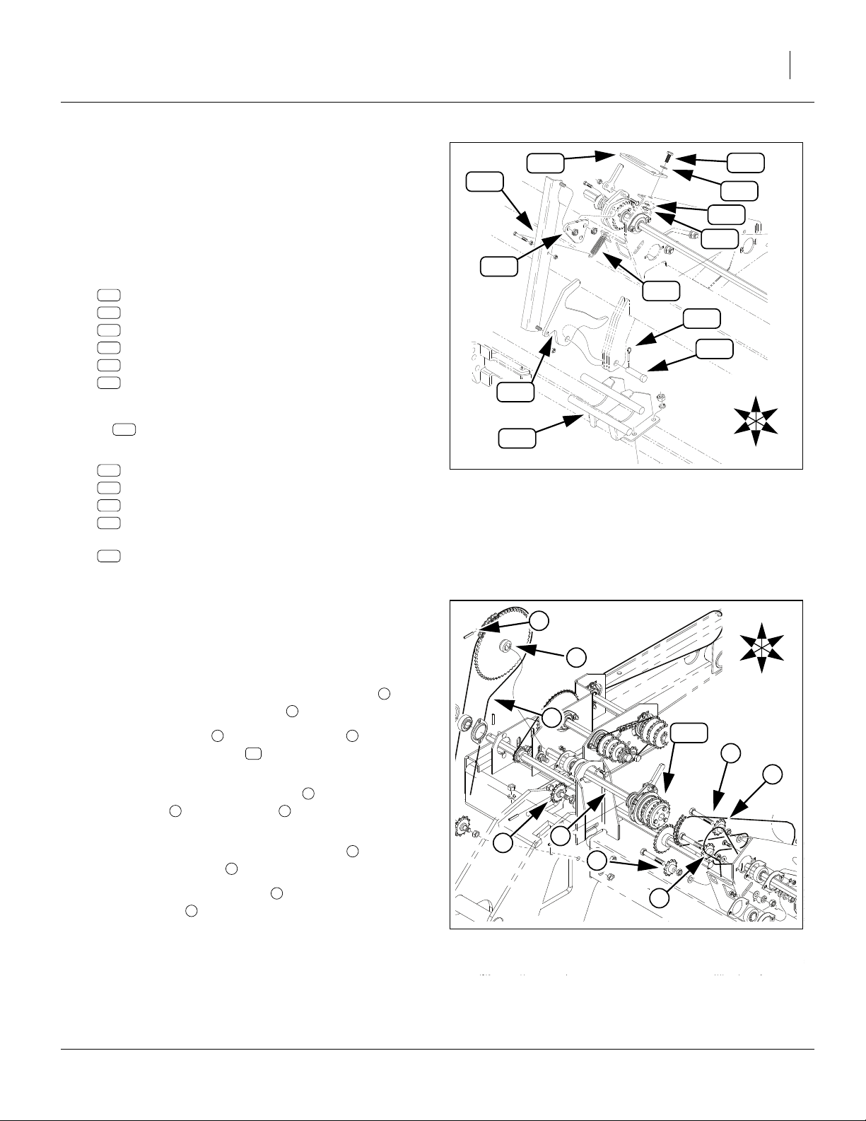
24 Electric Clutch Package Great Plains Manufacturing, Inc.
Refer to Figure 36
66. Select one new:
20
195-345D CLUTCH TORQUE ARM TAB
and two sets new:
30
802-079C HHCS 3/8-16X1 1/4 GR5
41
804-011C WASHER FLAT 3/8 USS PLT
42
804-013C WASHER LOCK SPRING 3/8 PLT
36
803-014C NUT HEX 3/8-16 PLT
67. Loosely mount the tab at the same Drive Type
bracket weldment holes used by the tab
removed at step 41.
68. Center clutch torque arm in the large hole in the
torque tab .
20
20
h
t
101
R
F
54
U
20
t
36
B
136
L
30
41
h
42
D
Refer to Figure 36 and Figure 37
69. Re-mount chains ( , ). Engage Drive Type chain
idler for
Engage option jackshaft chain idler for
slack in longest chain span.
70. Tighten tab bolts to torque specifications.
1
i
⁄
2
n u
in (13mm) slack in longest chain span.
1
v
⁄
in (6mm)
4
30
2S-2600F/SGS RH Closeout
71. Select one new (not shown):
55
833-088C OGURA CLUTCH JUMPER HARNESS
Connect the jumper to the clutch cable.
Refer to Figure 38
72. Re-mount gauge wheel chain on sprocket .
Engage idler for 1in (2.7cm) slack in longest chain
span.
a
c k
Install 2S-2600F/SGS Electronics
Continue at “2S Electrical Installation” on page 25.
These steps are common to both 2S-2600 and 2S2600F/SGS models.
R
F
R
F
Figure 36: 2S-2600F/SGS:
Install RH Torque Arm Tab
u
v
U
B
L
D
Figure 37: 2S-2600F/SGS:
Remount RH Drive Type Chain
c
U
B
L
D
Figure 38: 2S-2600F/SGS:
Remount RH Ground Drive Chain
28146
i
n
28057
k
a
28057
195-073M 03/24/2009
Page 29
Great Plains Manufacturing, Inc. 2S Electrical Installation 25
2S Electrical Installation
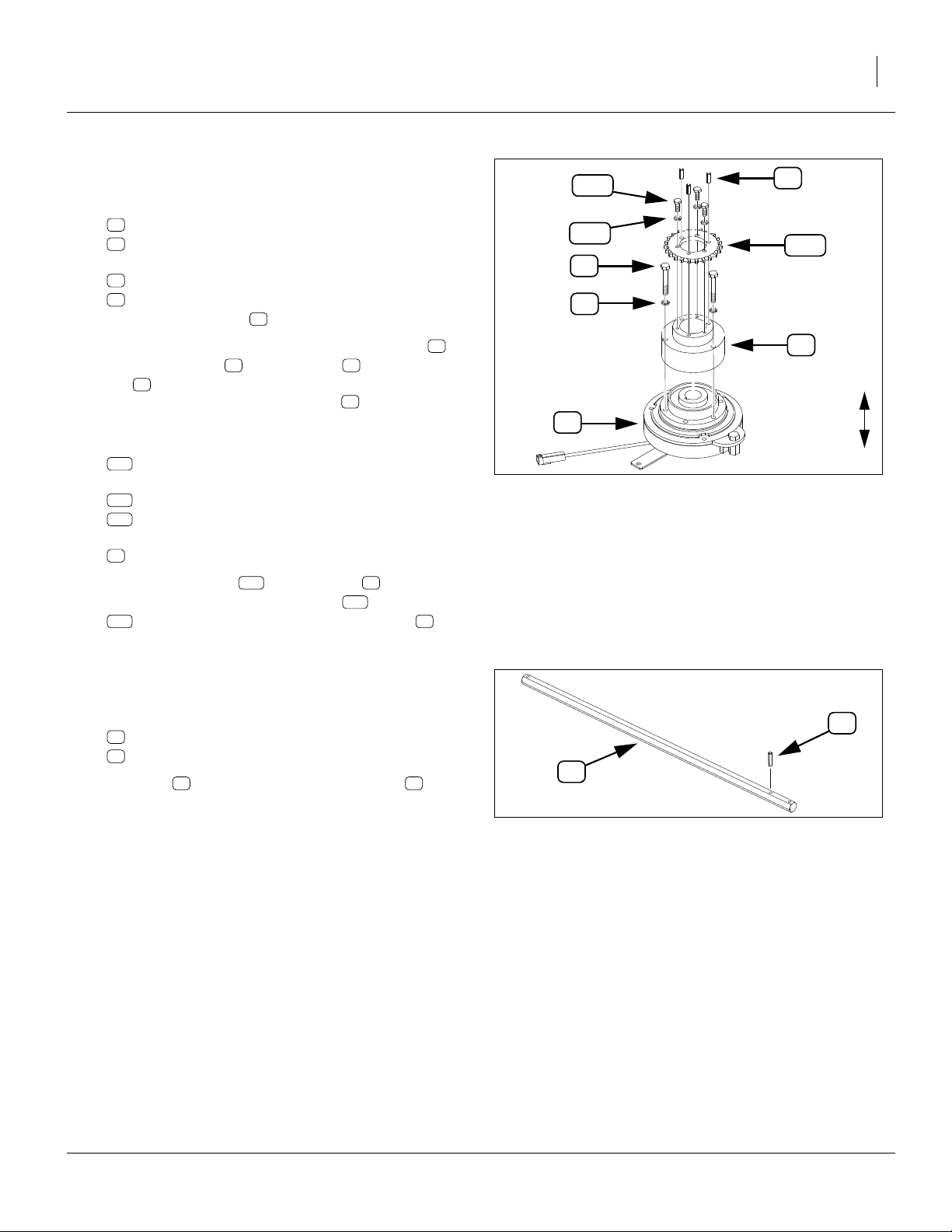
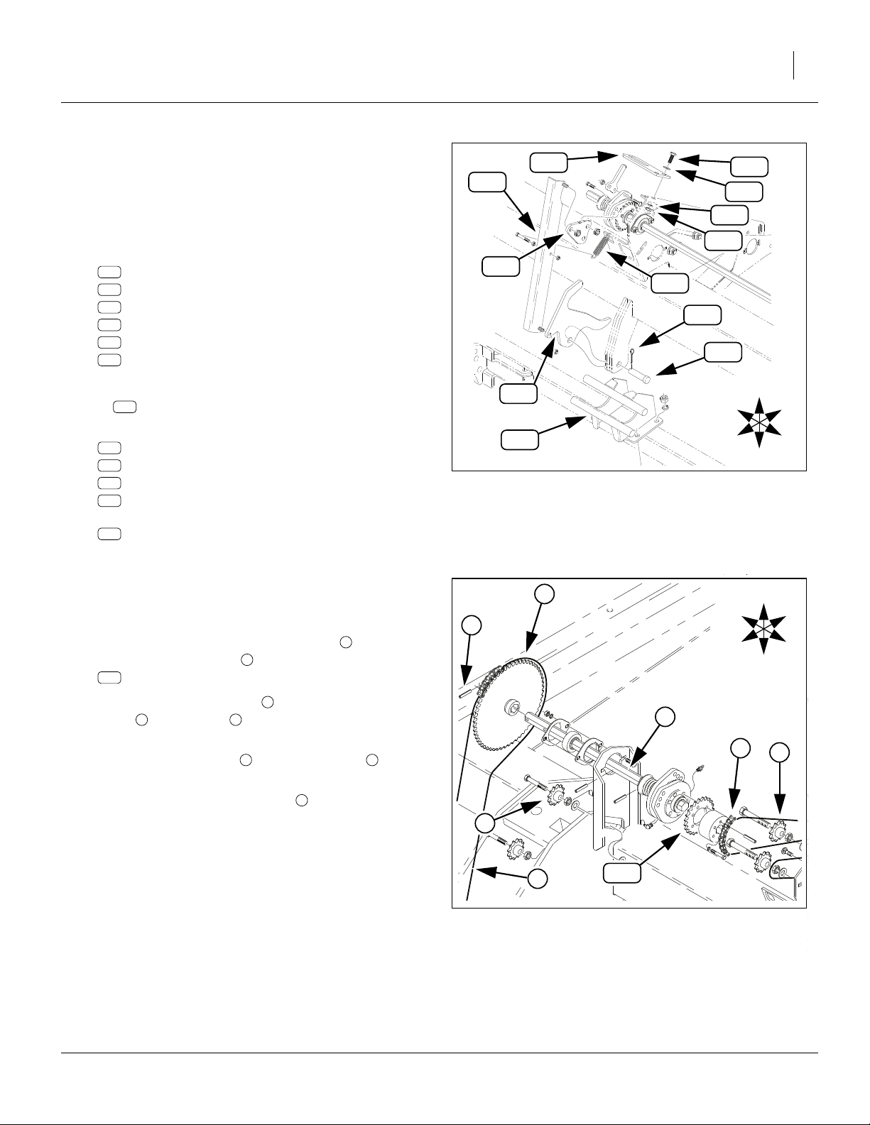
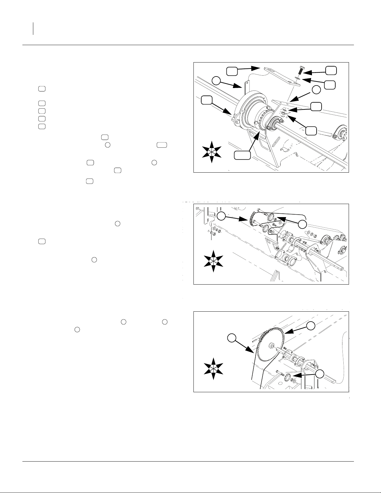
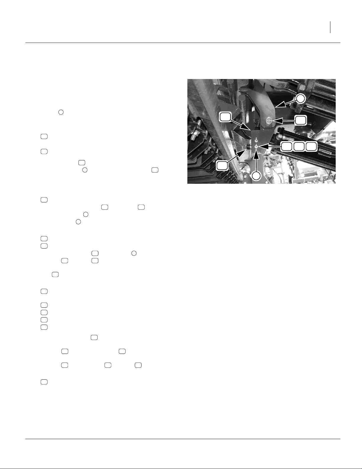
Install 2S Height Switch
Refer to Figure 39 (which depicts a 3S center section - installation on the 2S left section is identical)
The electric clutch system is activated by cab switches
and by a single height switch at the right hand shutoff
pivot plate (where a mechanical linkage was
x
removed).
1. Select one each new:
32
802-212C HHCS 3/4-10X2 1/2 GR5
and three:
44
804-024C WASHER FLAT 3/4 USS PLT
19
47
32
45
x
38
2. Insert the bolt part way into the right side of the
right pivot plate . Add three flat washers (not
32
x44
shown) in between the plates. Continue inserting the
bolt to retain the washers.
3. Select one each new:
19
195-344D LIMIT SWITCH BRACKET
Add the switch bracket to the bolt at the left
side of the plate . Orient the bracket extension with
the #10 slots toward drill rear.
z
19 32
x
4. Select one each new:
43
804-023C WASHER LOCK SPRING 3/4 PLT
37
803-027C NUT HEX 3/4-10 PLT
Secure the bracket to the plate with a lock
washer and nut , finger tight. Orient the rear
43 37
19 x
edge of the bracket to approximately vertical. Tighten
32
bolt to torque specification.
5. Select one new:
59
VER-28383 VERIS SPEED SNSR SWITCH HRNESS
and two sets new:
29
801-067C SCREW RD HD 8-32 X 1 1/2LG PLT
47
804-088C WASHER FLAT #8 SAE PLT
45
804-043C WASHER LOCK #8
38
803-064C NUT HEX 8-32
6. Position the switch , with the actuator arm to the
59
rear, and the cable up, against the left side of the
bracket . Insert a #8 screw (not shown)
19 29
through the switch body and bracket. Secure with flat
washer , lock washer and nut .
47 45 38
7. Select one new (not shown):
57
833-489C 2-WIRE AMP - WEATHERPACK ADAPT
Connect the adaptor to the switch lead.
The final position of the switch is adjusted at “Adjust
Height Switch” on page 90.
59
z
Figure 39: 2S:
Height Switch Installation
28096
03/24/2009 195-073M
Page 30
26 Electric Clutch Package Great Plains Manufacturing, Inc.
Install 2S Drill Cables
S
R
L
n/c
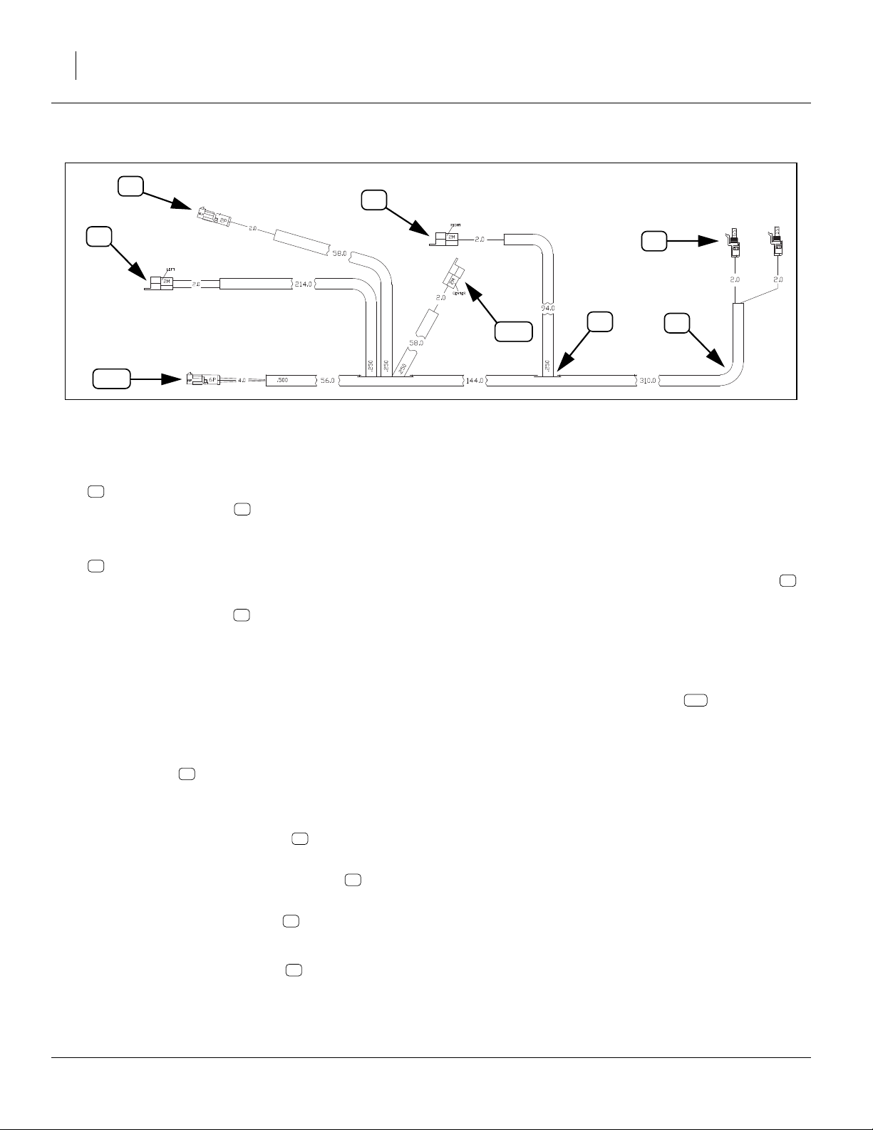
Figure 40
2-Section Drill Cabling
Refer to Figure 40 (dimensions are inches)
8. From the bundle:
56
833-294C 40P PNT RW CLTCH CNTRL & HRNSS
select the drill harness . which is a long cable
assembly with 7 connectors.
9. Select all of:
28
800-082C CABLE TIE .31X21.5 6DIA 120LB
10. Fish the cable snake through the tongue tube.
11. Wrap hitch connectors of the harness so that
they cannot snag, and secure that end of the harness to the rear end of the snake.
Route Cables
12. Pull the cable forward until it appears at the hitch end
of the tongue tube. Continue pulling until:
there is ample slack for making tractor connections
at the hitch, but not so much that the cable can touch
the ground in operations, and do not pull the first
cable junction into the tube.
13. Route the rear end of the cable, following hydraulic
hoses, to the right clutch.
J
H
H
T
n/c
Dress and Secure Cables
17. Dress cables to prevent entanglement with or chafing by drill moving parts. Leave ample slack at drill
center for folding (ideally, route the wing cables
directly above wing pivot center lines). Coil any
excess cable at drill center.
18. At the hitch end of the harness, use one cable tie
to secure the harness to clamped hydraulic hoses.
19. Use 1 tie to secure the switch lead and harness
switch leg.
20. Use 3 ties on each wing to secure the wing runs.
21. Near the right clutch, coil the unused “CENTER” and
“PUMP” (or unlabeled) cable legs and any any
excess cable. Use one tie to secure them.
J
H
28096
28
n/c
14. Mate harness connector “Right” to the jumper
cable on the right clutch.
15. Route harness cable leg “Height Switch” down to
the switch, and mate the connectors.
16. Route harness cable leg “Left” back to drill center, and out to the left clutch. Route across the rear
of the tongue, and not across the gap between the
wing tool bars. Mate connector to the left clutch
jumper cable.
195-073M 03/24/2009
R
S
L
L
Page 31

Great Plains Manufacturing, Inc. Update 3S-3000 Left Hand Drive 27
3S-3000 Main Box Only Installation
This section describes installation of kit 195-078A for:
• 3S-3000 s/n S1563+ (1996+) drills with only main
seed box, and no Small Seeds/Fertilizer options or;
• 3S-3000HD drills with only a main seed box, and no
Small Seeds or Fertilizer options.
Update 3S-3000 Left Hand Drive
Remove 3S-3000 LH Linkage
Steps 1-4 are on page 4.
Refer to Figure 41 (which depicts a 2S-2600 linkage, but the
parts removed for 3S-3000 are the same)
5. Remove individually or as an assembly:
106
195-130H CLUTCH SHUTOFF LINK, 00 SERIES
108
195-144D CLUTCH SHUTOFF CAM, 00 SERIES
118
195-254D CLUTCH PULL TAB
132
805-083C PIN CLEVIS 3/4 X 1 1/2
133
805-109C PIN COTTER 1/8 X 1 1/4 PLT
134
807-072C SPRING EXT 1 1/16 ODX.120WX5.5
These parts are not re-used.
Note: This part may be removed or left in place:
107
195-131H SUBFRM CLUTCH BRKT,SOLID STAND
6. Remove two sets:
124
802-079C HHCS 3/8-16X1 1/4 GR5
129
804-011C WASHER FLAT 3/8 USS PLT
130
804-013C WASHER LOCK SPRING 3/8 PLT
127
803-014C NUT HEX 3/8-16 PLT
and remove the:
101
152-263D CLUTCH ENGAGE TAB
These parts are not re-used.
For other kits, see:
2S-2600, main box only, 195-076A kitpage 5
2S-2600, w/option box(es), 195-077A kitpage 15
3S-3000, w/option box(es), 195-078A kitpage 42
3S-4000, main box only, 195-075A kitpage 61
3S-4000, w/option box(es), 195-075A kitpage 74
101
106
124
129
130
127
118
134
133
132
108
R
107
Figure 41: 3S-3000:
Remove LH Linkage
F
U
B
L
D
17253
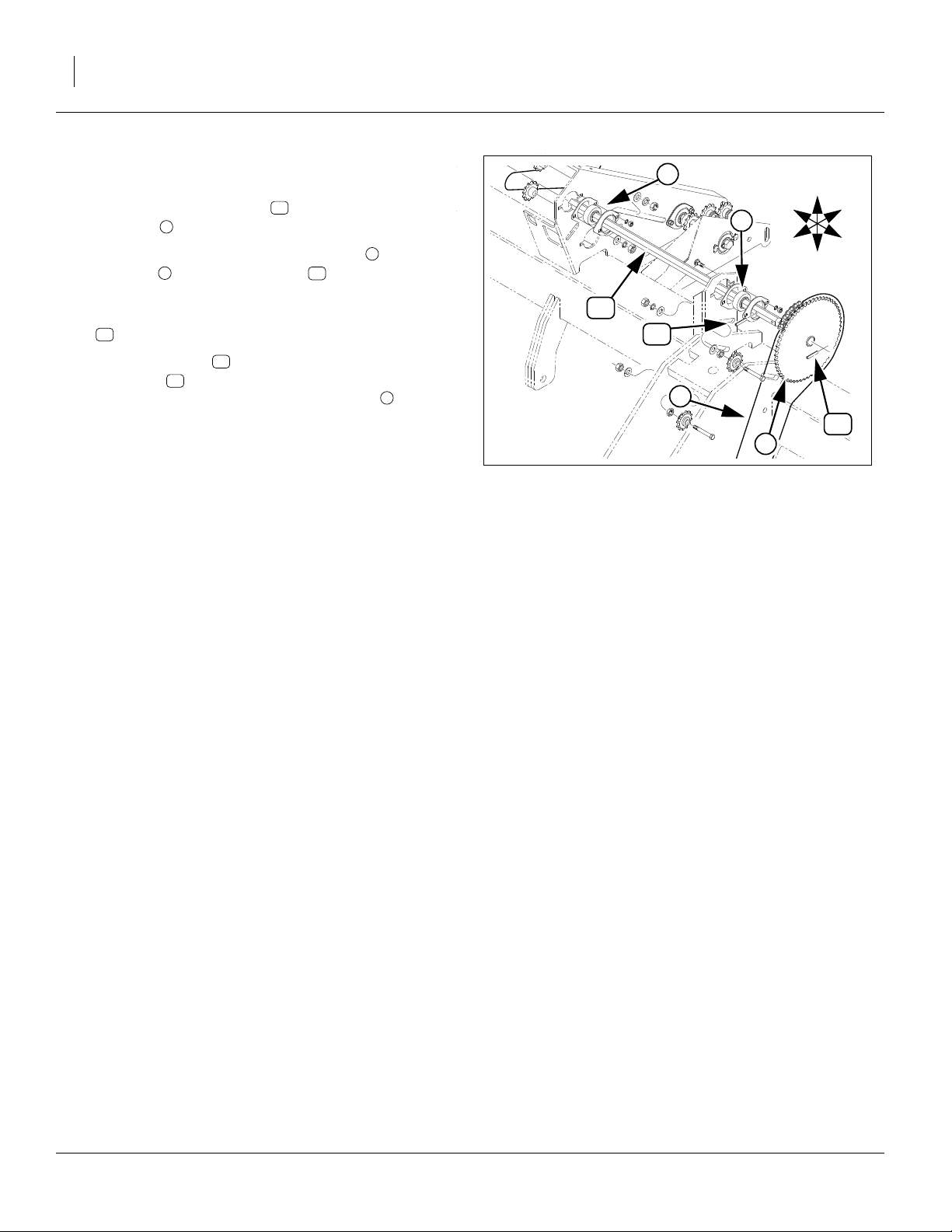
Remove 3S-3000 LH Shaft and Clutch
Dismount Clutch Output Chain
Refer to Figure 42
7. Loosen idler and lift chain off of sprocket:
136
808-240C SPKT 40A23X1.813-1.818 BR/6HOL
Do not completely remove the chain.
i n
136
n
i
U
R
B
102
F
L
115
D
Figure 42: 3S-3000:
Dismount LH Clutch Chain
03/24/2009 195-073M
21627
Page 32

28 Electric Clutch Package Great Plains Manufacturing, Inc.
Dismount Ground Drive Chain & Sprocket
R
F
U
B
L
D
e
Refer to Figure 43
8. Loosen idler in gauge wheel assembly.
Lift ground drive chain off sprocket .
Do not completely remove the chain.
9. Drive the roll pin out of the left end of shaft:
115
195-189D POWER SHAFT 7/8 HEX LH
This pin is not re-used.
10. Remove and save sprocket .
Remove 3S-3000 LH Drive Shaft
CAUTION
!
115
Shaft moves, under spring tension, about
the right as the next pin is removed.
a
c k
e
k
1
⁄
in (13mm) to
2
f
115
a
c
11. Drive out the mid roll pin . Pin is not re-used.
12. Remove the shaft from the drill (slide out to
right, with the clutch still mounted).
115
f
Disassemble 3S-3000 LH Clutch
Refer to Figure 44
13. At the clutch assembly , remove and save three
sets:
123
802-004C HHCS 1/4-20X3/4 GR5
128
804-006C WASHER LOCK SPRING 1/4 PLT
14. The sprocket may still be held by pins. Remove and
save the sprocket:
136
808-240C SPKT 40A23X1.813-1.818 BR/6HOL
Any roll pins present, the shaft, and the balance of
the clutch assembly are not re-used.
102
Pre-Assemble 3S-3000 LH Clutch
Refer to Figure 45
15. Select one each new:
54
823-231C OGURA CLUTCH
22
195-347D ELECTRIC CLUTCH ADAPTOR
and three sets new:
34
802-684C HHCS M8X1.25X55 GR8.8
48
804-157C WASHER SPRING LOCK M8 PLT
Place the tab end of down on a work surface.
Note that the 195-347D adaptor has alternating
smooth and tapped (threaded)
16. Secure the large end of the 195-347D adaptor to
the Ogura clutch with the bolts and lock wash-
48
ers . Torque to specifications (see page 93).
54
22
1
⁄
in holes.
4
54 34
22
102
Figure 43: 3S-3000:
Release LH Power Shaft
Figure 44: 3S-3000:
Disassemble LH Clutch
34
48
54
Figure 45: 3S-3000
Pre-assemble LH Clutch
136
128
k
123
102
22
R
F
21627
U
B
L
D
115
28106
U
D
28144
195-073M 03/24/2009
Page 33

Great Plains Manufacturing, Inc. Update 3S-3000 Left Hand Drive 29
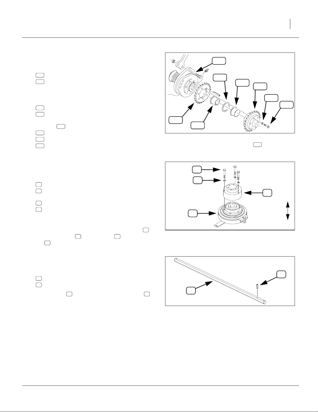
Prepare New 3S-3000 LH Power Shaft
Refer to Figure 46
17. Select one each new:
21
195-346D SHAFT 7/8 HEX 32.44 LG
50
805-180C PIN ROLL 1/4 X 1 1/2 LG PLT
18. Drive pin into the inner hole of the shaft .
50 21
21
50
Install New 3S-3000 LH Power Shaft
Refer to Figure 47 (which, for clarity, is a fully exploded
view)
19. From drill left, insert shaft into the existing flanged
bearings .
20. Select the saved ground drive sprocket . Place the
sprocket onto the new shaft , with the raised
hub of the sprocket to drill right (towards bearings).
21. Select one new:
50
805-180C PIN ROLL 1/4 X 1 1/2 LG PLT
22. Drive the roll pin into the hole at the left end of
new shaft , securing the sprocket.
Note: Do not remount the ground drive chain at this
time.
b
k21
50
21
21
k
c
R
28094
U
B
Figure 46: 3S-3000:
Pin New LH Shaft
b
b
F
n
L
D
21
50
c
50
k
Figure 47: 3S-3000:
Install LH Power Shaft
28056
03/24/2009 195-073M
Page 34

30 Electric Clutch Package Great Plains Manufacturing, Inc.
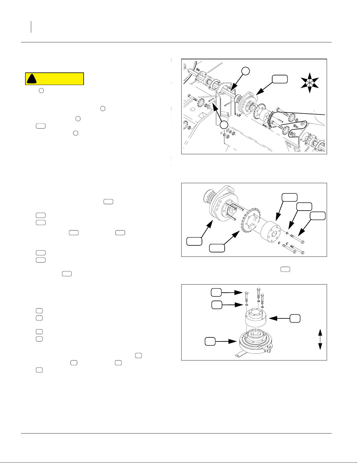
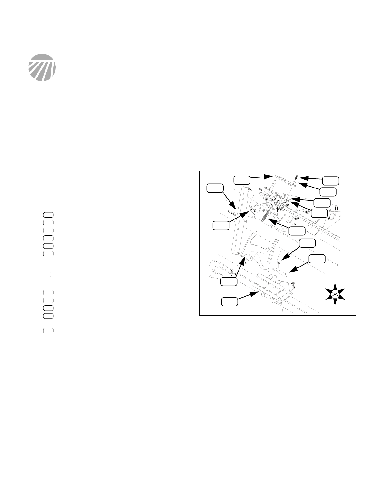
Install 3S-3000 LH Clutch
Refer to Figure 48
23. Select two new:
46
804-061C WASHER MACH 1.50 X 1.00 X 18GA
and one new:
24
195-349D WING FERT CLUTCH OUTER SPCR TB
Place the washers , followed by the spacer , on
the shaft .
24. Select one each new:
13
195-160H
51
817-111C BSHG FLG 1.26IDX1.41ODX.87L
12
176-065D CLUTCH FRICTION WASHER
15
195-222D BRG 7/8 HEX ID X 1.254 OD
With any flanged ends to the right, place the bushing
51 12 15
, the friction washer and the bearing inside
the sprocket .
25.
Select three sets new:
31
802-152C HHCS 1/4-20X2 GR5
39
804-006C WASHER LOCK SPRING 1/4 PLT
Orient the sprocket with the larger raised hub to
drill right. Place the bolts through the lock washers and into every other hole of the left face.
Place sprocket , bolt face left, on the shaft .
26. Select the saved:
136
and one new:
25
195-350D WING FERT CLUTCH INNER SPCR TB
Place them on the shaft .
27. Select the clutch assembled at step 16 and one
each new:
26
196-877D BUSHING 1 1/8 ODX7/8 HEX BORE
58
839-956C KEY 1/4 X 3/16 X 3.80
Insert the bushing in the clutch assembly .
Align the keyways of the bushing and the Ogura
clutch. Insert the key
28. With the tab end to drill right, place the clutch
assembly on shaft . Align the threaded holes
of the adaptor with the bolts . Screw in the
bolts, finger-tight.
29. Select three new
50
805-180C PIN ROLL 1/4 X 1 1/2 LG PLT
Drive the roll pins into the smooth holes. Tighten
bolts to specification. Re-seat roll pins as required.
21
39
808-240C SPKT 40A23X1.813-1.818 BR/6HOL
54 21
46 24
SPKT CLUTCH 40B23T RND BORE
18
18
31
18 21
21
54
26 54
58
22 31
50
50
46
54
30. Move the clutch assembly to drill left.and into the
Drive Type chain
31. Select two new:
46
804-061C WASHER MACH 1.50 X 1.00 X 18GA
Place them on the shaft .
32. Select one new:
50
805-180C PIN ROLL 1/4 X 1 1/2 LG PLT
Drive the pin into the hole at the right end of the
shaft , to secure all the components just installed
on the shaft.
Note: One of the sprockets attached to the clutch is
unused on the standard 3S-3000. The second
sprocket is provided to ease any future upgrade to
Fertilizer and/or Small Seeds capability.
21
58
26
22
25
15
12
n
Figure 48: 3S-3000
Install LH Clutch
54
n
50
51
21
136
39
13
50
31
R
F
U
B
L
D
24
46
21
28154
195-073M 03/24/2009
Page 35

Great Plains Manufacturing, Inc. Update 3S-3000 Left Hand Drive 31
Install 3S-3000 LH Torque Tab
Refer to Figure 49
33. Select one new:
20
195-345D CLUTCH TORQUE ARM TAB
and two sets new:
30
802-079C HHCS 3/8-16X1 1/4 GR5
41
804-011C WASHER FLAT 3/8 USS PLT
42
804-013C WASHER LOCK SPRING 3/8 PLT
36
803-014C NUT HEX 3/8-16 PLT
34. Loosely mount the tab at the same Drive Type
bracket weldment holes used by the tab
removed at step 6.
35. Rotate the clutch housing until the torque arm
is nearly vertical. Route it through the large hole in
the torque tab . Tighten the bolts to torque
specifications.
20
20
h
54 t
30
101
54
20
41
30
t
h
42
36
U
R
B
3S-3000 LH Closeout
Refer to Figure 44 on page 28
36. Re-mount Drive Type chain . Engage idler for
1
⁄
in (13mm) slack in longest chain span.
2
Refer to Figure 50
37. Re-mount gauge wheel chain on sprocket .
Engage idler for 1in (2.7cm) slack in longest chain
span.
a
n i
c k
F
L
D
Figure 49: 3S-3000:
Install Torque Arm Tab
28146
a
c
U
R
F
B
L
k
D
Figure 50: 3S-3000:
Re-Install LH Gauge Wheel Chain
28056
03/24/2009 195-073M
Page 36

32 Electric Clutch Package Great Plains Manufacturing, Inc.
Update 3S-3000 Center Drive
For the center section to be under independent clutch
control, the existing solid drive shaft is replaced by two
smaller shafts, coupled at the new clutch.
Remove 3S-3000 Center Components
Refer to Figure 51
38. Remove and save the acremeter at the left end of
the center shaft . Remove this instrument before
driving out any pins.
39. Loosen Drive Type idler and lift chain (not shown)
off shaft output sprocket . Do not completely
remove chain.
40. Drive roll pin out of the left end of the shaft .
41. Remove and save one:
137
808-259C SPKT 40B14 X 7/8 HEX BORE
42. To the left of bearing , drive roll pin out of shaft
114
. Remove the shaft from the drill.
114
i
137
1
b 2
o
105
134
104
131
114
114
R
F
U
B
L
D
4
i
3
b
2
CAUTION
!
Washer moves, under spring tension, about
to the left as the next pin is removed.
131
1
⁄
in (13mm)
2
137
43. To the left of washer , drive roll pin out of shaft
114
. Removal of the last pin is optional.
44. Remove from the shaft and save one each:
105
195-109D BRKAWAY CLUTCH 7/8 HX LONG BR
134
807-097C SPRING COMP 2 1/16 OD X 4 LG
104
176-066D CLUTCH SPRING RETAINER
131
804-061C WASHER MACH 1.50 X 1.00 X 18GA
the removed shaft
114
195-188D POWER SHAFT 7/8 HEX CENTER
is not re-used.
131
4
:
3
1
Figure 51: 3S-3000:
Dismantle Center Shaft
o
21634
195-073M 03/24/2009
Page 37

Great Plains Manufacturing, Inc. Update 3S-3000 Center Drive 33
Install 3S-3000 CTR Clutch Bearing
Refer to Figure 52
45. Select one:
53
822-119C BRG 7/8HEXX2.05OD SPH
and two:
52
822-032C FLANGETTE 52 MST
and two sets:
33
802-282C RHSNB 5/16-18X1 GR5
40
804-009C WASHER LOCK SPRING 5/16 PLT
35
803-008C NUT HEX 5/16-18 PLT
46. Assemble the bearing between the flangettes .
Mount the bearing from the left side of the option
drive bracket . Insert the bolts from the right
side, and loosely secure with lock washers and
35
nuts (some adjustment may be necessary).
133
53 52
40
R
F
33
1
U
B
L
52
53
52
40
35
D
Install 3S-3000 CTR Driven Shaft
Refer to Figure 53
47. Select one each new:
14
195-168D POWER SHAFT 7/8 HEX CTR CLUTCH
50
805-180C PIN ROLL 1/4 X 1 1/2 LG PLT
Drive the pin into the hole at the solid end of the
shaft (the end that is not tapped with 1/2-20 threads)
48. Insert the shaft, from the right, into the new bearing
53 b
, and the existing bearing at the Drive Type
assembly.
49. Select one saved:
137
808-259C SPKT 40B14 X 7/8 HEX BORE
and one new:
50
805-180C PIN ROLL 1/4 X 1 1/2 LG PLT
with the raised hub side to the right, place the
sprocket on the shaft . Drive the roll pin into
the hole at the left end of the shaft.
50. Select the saved acremeter . Screw, hand-tightonly, it into the 1/2-20 hole at the end of the shaft.
Note: The fasteners at the new bearing are not tight-
ened at this time. The shaft may need to be aligned
with the new driving shaft.
137
14
o
53
50
R
F
53
U
D
Figure 52: 3S-3000:
Install Clutch Bearing
B
b
L
Figure 53: 3S-3000:
Install Driven Shaft
28110
14
137
o
50
28150
03/24/2009 195-073M
Page 38

34 Electric Clutch Package Great Plains Manufacturing, Inc.
Prepare 3S-3000 CTR Driving Shaft
Refer to Figure 54
51. Select one each new:
16
195-231D SHAFT 7/8 HEX,POINT ROW-CENTER
50
805-180C PIN ROLL 1/4 X 1 1/2 LG PLT
Note that the right end of the shaft is the end with
3 holes. Drive the roll pin into the hole nearest the
right end of the shaft .
52. Select one each saved:
105
195-109D BRKAWAY CLUTCH 7/8 HX LONG BR
134
807-097C SPRING COMP 2 1/16 OD X 4 LG
104
176-066D CLUTCH SPRING RETAINER
131
804-061C
and one new:
50
805-180C PIN ROLL 1/4 X 1 1/2 LG PLT
53. Compress the spring and secure it in compression with some wire.
54. With the clutch jaws toward the pinned (right)
end of the shaft , place the clutch on the shaft.
Place the compressed spring on the shaft.
55. With the larger flared end of the retainer to the
left (away from the spring), place the retainer on the
shaft against the spring, followed by the washer .
56. Drive the roll pin into the hole second from the
right end of the shaft. Release the wire securing the
spring.
57. Insert the left end of the shaft through the right side
of the bearing . Do not pin the shaft in place at this
time.
WASHER MACH 1.50 X 1.00 X 18GA
16
50
b
50
16
134
105
16
134
104
131
105
134
104
131
b
50
50
Figure 54: 3S-3000:
Prepare Driving Shaft
R
F
U
B
L
D
28113
Pre-Assemble 3S-3000 CTR Clutch
Refer to Figure 55
58. Select one each new:
54
823-231C OGURA CLUTCH
22
195-347D ELECTRIC CLUTCH ADAPTOR
and three sets new:
34
802-684C HHCS M8X1.25X55 GR8.8
48
804-157C WASHER SPRING LOCK M8 PLT
Set the clutch assembly on a work surface, with the
torque arm end of the Ogura clutch down.
59. Secure the large end of the 195-347D adaptor to
the Ogura clutch with the bolts and lock wash-
48
ers . Torque to specifications.
195-073M 03/24/2009
54 34
22
34
48
54
Figure 55: 3S-3000:
Pre-assemble LH Clutch
22
U
D
28144
Page 39

Great Plains Manufacturing, Inc. Update 3S-3000 Center Drive 35
Install 3S-3000 CTR Clutch
Refer to Figure 56
60. Select one new:
27
402-025S LOCK COLLAR, 7/8 HEX W/ SET SC
which, if not pre-assembled, consists of:
60
1 402-058D COLLAR LOCK 7/8 HEX and
61
2 801-035C SCREW SET 5/16-18 SKT KP X 3/8
Adjust set screws to clear the collar hex hole.
Place the collar on the left end of the clutch input
16
shaft . Do not tighten the set screws at this time.
61
27
61. Select two new:
46
804-061C WASHER MACH 1.50 X 1.00 X 18GA
Place them on the input drive shaft .
62. Select the clutch assembled at step 59. Note that
the 195-347D adaptor has alternating smooth
and tapped (threaded)
54
22
1
⁄
in holes.
4
16
63. Select one each new:
26
196-877D BUSHING 1 1/8 ODX7/8 HEX BORE
58
839-956C KEY 1/4 X 3/16 X 3.80
Place bushing inside clutch . Align keyways of
bushing and Ogura clutch . Insert key .
26 54 58
Place the clutch, tab end to right, on input shaft .
54
16
64. Select one new:
23
195-348D CLUTCH SPACER TUBE
Insert it in the left end of the adaptor .
22
27
b
50
26
46
58
61
16
Figure 56: 3S-3000:
Install CTR Clutch
54
22
23
18
39
31
R
F
U
B
L
D
50
46
35
14
28113
Note: The 23T sprocket on adaptor/sprocket is not
18
connected to a chain on the standard 3S-3000.
This sprocket is included to ease a future upgrade
to Fertilizer and/or Small Seeds capability.
65. Select one new:
18
195-280H SPKT CLUTCH 40B23T 7/8HEX BORE
and three sets new:
31
802-152C HHCS 1/4-20X2 GR5
39
804-006C WASHER LOCK SPRING 1/4 PLT
Place the hex bore sprocket on the clutch adaptor
22 31
and align the holes. Loosely secure the bolts
and washers in the threaded holes (every other
hole) of the adaptor .
39
22
18
66. Select three new:
50
805-180C PIN ROLL 1/4 X 1 1/2 LG PLT
Drive the roll pins into the smooth holes of the
195-347D adaptor . Tighten bolts to specification.
49
22
Re-seat roll pins as necessary.
67. Select seven (7) new:
46
804-061C WASHER MACH 1.50 X 1.00 X 18GA
Place them on the driven shaft .
14
68. Select one new:
50
805-180C PIN ROLL 1/4 X 1 1/2 LG PLT
Shift the driving shaft to drill left, until the second
16
of the two left roll pin holes appears to the left of the
right bearing (one hole is inside the clutch). Drive
the pin into the drive shaft mid hole.
69. Shift the clutch assembly to drill left, until the left
b
50 16
54
end of clutch has captured the right end of driven
14 27 46
shaft . Slide collar and washers left against
clutch . Secure set screws.
70. Rotate the driven shaft a few turns to ensure it is
aligned with the driving shaft . Tighten the nuts
54
14
16 35
at the clutch bearing.
03/24/2009 195-073M
Page 40

36 Electric Clutch Package Great Plains Manufacturing, Inc.
Install 3S-3000 CTR Torque Tab
Refer to Figure 57
71. Select one new:
20
195-345D CLUTCH TORQUE ARM TAB
and two sets new:
30
802-079C HHCS 3/8-16X1 1/4 GR5
41
804-011C WASHER FLAT 3/8 USS PLT
42
804-013C WASHER LOCK SPRING 3/8 PLT
36
803-014C NUT HEX 3/8-16 PLT
72. Loosely mount the tab at the middle bracket.
73. Rotate the clutch until the torque arm is in the
large hole in the torque tab .
74. Tighten tab bolts to torque specifications.
20
54 t
20
30
3S-3000 Center Closeout
75. Re-mount the Drive Type chain (not shown). Engage
idler (not shown) and adjust for slack of
76. Select one new (not shown):
55
833-088C OGURA CLUTCH JUMPER HARNESS
Connect the jumper to the clutch cable.
1
⁄
in (13cm).
2
R
F
20
t
54
36
U
B
L
D
Figure 57: 3S-3000:
Install CTR Torque Arm Tab
30
41
h
42
28148
Update 3S-3000 Right Hand Drive
On this section, two coupled shafts are replaced by a single solid shaft.
Remove 3S-3000 RH Linkage
Refer to Figure 58 (which depicts the LH linkage, but the
parts to be removed, and their general arrangement, are
identical on the RH side)
77. Remove individually or as an assembly:
106
195-130H CLUTCH SHUTOFF LINK, 00 SERIES
108
195-144D CLUTCH SHUTOFF CAM, 00 SERIES
118
195-254D CLUTCH PULL TAB
132
805-083C PIN CLEVIS 3/4 X 1 1/2
133
805-109C PIN COTTER 1/8 X 1 1/4 PLT
134
807-072C SPRING EXT 1 1/16 ODX.120WX5.5
These parts are not re-used.
Note: This part may be removed or left in place:
107
195-131H SUBFRM CLUTCH BRKT,SOLID STAND
78. Remove two sets:
124
802-079C HHCS 3/8-16X1 1/4 GR5
129
804-011C WASHER FLAT 3/8 USS PLT
130
804-013C WASHER LOCK SPRING 3/8 PLT
127
803-014C NUT HEX 3/8-16 PLT
and remove the:
101
152-263D CLUTCH ENGAGE TAB
These parts are not re-used.
106
118
108
107
101
Figure 58: 3S-3000:
Remove RH Linkage
134
133
132
129
130
127
R
F
124
U
B
L
D
17253
195-073M 03/24/2009
Page 41

Great Plains Manufacturing, Inc. Update 3S-3000 Right Hand Drive 37
Replace 3S-3000 RH Drive Shafts
Remove 3S-3000 RH Chains and Input Sprocket
Refer to Figure 59
79. At the Drive Type bracket, loosen idler and lift
Drive Type drive chain off clutch output sprocket
136
. Do not completely remove the chain.
80. Loosen ground drive idler (not shown) and lift ground
drive chain (not shown) off sprocket . Do not com-
pletely remove the chain.
81. Drive right end roll pin out of input shaft . Pin is
not re-used.
82. Remove and save the sprocket .
CAUTION
!
The pin removed in the next step is under lateral spring tension
from the clutch assembly. Parts of the clutch assembly will
jump to the right about
withdrawn.
n
r d
k
1
⁄
in (13mm) as the pin or punch is
2
i
k
k
r
d
136
f
102
F
R
i
U
B
L
D
s
n
83. Drive out mid pin . It is not re-used.
Remove 3S-3000 RH Input Shaft and Clutch
84. Move the shaft to the left. Remove the:
102
176-042S JAW CLUTCH CW EXT 7/8 HEX
from the shafts and .
85. Remove the shaft from in the drill. It is not reused.
f
d
d s
d
Figure 59: 3S-3000:
RH Chains and Input Sprocket
21631
Remove 3S-3000 RH U-Joint Shaft
Refer to Figure 60
86. At the left end of driven shaft , drive out roll pin .
The pin is not re-used.
87. Slide the right end of the U-joint off the shaft .
88. As needed, drive the mid pin from shaft .
Remove shaft @ from the drill. The shaft and pin are
not re-used.
Install 3S-3000 Solid Shaft
89. Select one new:
17
195-232D SHAFT 7/8 HEX, POINT ROW-RH
Note that the shaft has 3 pin holes. Only end holes
are used on 3S-3000, but there is a left and right
end. At the left end of the shaft, the hole is 1/2in
(12.7mm) from the end of the shaft. At the right end,
the hole is 3/8in (9.5mm) from shaft end.
Insert the right end of the shaft through the left
bearing and about 6in (15cm) through the mid
bearing . Insert no pins at this time.
2
3
s e
1 s
f s
17
3
R
F
s
B
L
D
f
e
1
2
U
Figure 60: 3S-3000:
Remove Driven Shaft
28156
03/24/2009 195-073M
Page 42

38 Electric Clutch Package Great Plains Manufacturing, Inc.
Disassemble 3S-3000 RH Clutch
Refer to Figure 61
90. From the clutch assembly , remove and save
102
three sets:
126
802-551C HHCS 1/4-20X2 1/4 GR5
128
804-006C WASHER LOCK SPRING 1/4 PLT
The adaptor and sprocket and may still be
held together, and on the clutch , by roll pins.
111 136
102
91. Remove and save:
136
808-240C SPKT 40A23X1.813-1.818 BR/6HOL
Any roll pins present, the adaptor , and the balance of the clutch assembly , are not re-used.
111
113
102
136
Figure 61: 3S-3000:
Disassemble RH Clutch
111
128
126
28108
102
Pre-Assemble 3S-3000 RH Clutch
Refer to Figure 62
92. Select one each new:
54
823-231C OGURA CLUTCH
22
195-347D ELECTRIC CLUTCH ADAPTOR
and three sets new:
34
802-684C HHCS M8X1.25X55 GR8.8
48
804-157C WASHER SPRING LOCK M8 PLT
Place the clutch on a work surface, tab end down.
Note that the 195-347D has alternating smooth
and tapped (threaded)
93. Secure the large end of the 195-347D to the
Ogura clutch with the bolts and lock washers
48
. Torque to specifications (see page 93).
54 34
22
1
⁄
in holes.
4
22
34
48
54
Figure 62: 3S-3000:
Pre-assemble RH Clutch
22
U
D
28144
195-073M 03/24/2009
Page 43

Great Plains Manufacturing, Inc. Update 3S-3000 Right Hand Drive 39
Install 3S-3000 RH Clutch
Refer to Figure 63
94. Select one new:
24
195-349D WING FERT CLUTCH OUTER SPCR TB
Place the spacer on the right end of the drive
17
shaft .
95. Select one each new:
13
195-160H SPKT CLUTCH 40B23T RND BORE
51
817-111C BSHG FLG 1.26IDX1.41ODX.87L
12
176-065D CLUTCH FRICTION WASHER
15
195-222D BRG 7/8 HEX ID X 1.254 OD
With the thicker side of hub to the right, place the
sprocket on the right end of the drive shaft .
With any flanged ends to the right, place the bushing
51 12 15
drive shaft , inside the sprocket .
96. Select the saved:
136
and three sets saved:
126
128
Place the sprocket on the shaft , and loosely
combine it with the earlier sprocket by inserting
bolts through lock washers at every other
hole in the left face of sprocket .
97. Select one:
25
Insert the spacer inside the sprocket assembly .
98. Select the clutch assembled at step 72. Place it
on the shaft , over the spacer . Rotate the
clutch until the threaded holes of the adaptor
align with the bolts . Loosely screw in the bolts.
99. Select one each new:
26
58
Place bushing inside clutch . Align keyways of
bushing and Ogura clutch . Insert key
100.Select two new:
46
and one new:
27
which, if not pre-assembled, consists of:
60
1 402-058D COLLAR LOCK 7/8 HEX and
61
2 801-035C SCREW SET 5/16-18 SKT KP X 3/8
13 17
, the friction washer and the bearing on the
808-240C SPKT 40A23X1.813-1.818 BR/6HOL
802-551C HHCS 1/4-20X2 1/4 GR5
804-006C WASHER LOCK SPRING 1/4 PLT
126 128
195-350D WING FERT CLUTCH INNER SPCR TB
196-877D BUSHING 1 1/8 ODX7/8 HEX BORE
839-956C KEY 1/4 X 3/16 X 3.80
26 54 58
804-061C WASHER MACH 1.50 X 1.00 X 18GA
402-025S LOCK COLLAR, 7/8 HEX W/ SET SC
24
17 13
25 17
13
13
136
54
17 25
22
126
54
27
58
26
54
25
136
12
13
46
22
15
51
128
b
17
n
Figure 63: 3S-3000:
Install RH Clutch
101.Adjust set screws to clear the collar hex hole.
Place the collar on the left end of the shaft . Do
not tighten the set screws at this time. To prevent
part loss, slide input shaft to the right, just into
right support bearing .
102.Select three new:
50
805-180C PIN ROLL 1/4 X 1 1/2 LG PLT
Drive the roll pins into the empty holes of
sprocket . Tighten bolts to specification and
re-seat roll pins.
13
61
27 d
17
b
49
126
50
126
R
F
U
B
L
D
24
28158
03/24/2009 195-073M
Page 44

40 Electric Clutch Package Great Plains Manufacturing, Inc.
Install 3S-3000 RH Torque Tab
Refer to Figure 64
103.Select one new:
20
195-345D CLUTCH TORQUE ARM TAB
and two sets new:
30
802-079C HHCS 3/8-16X1 1/4 GR5
41
804-011C WASHER FLAT 3/8 USS PLT
42
804-013C WASHER LOCK SPRING 3/8 PLT
36
803-014C NUT HEX 3/8-16 PLT
104.Loosely mount the tab at the same Drive Type
bracket weldment holes used by the tab
removed at step 78.
105.Rotate the clutch until the torque arm is in the
large hole in the torque tab . Tighten tab bolts
to torque specifications.
Re-install 3S-3000 RH U-Joint
Refer to Figure 65
106.At left end of new shaft , align pin holes of shaft
and U-Joint . Slide U-Joint onto shaft.
107.Select one new:
50
805-180C PIN ROLL 1/4 X 1 1/2 LG PLT
Drive pin into U-Joint and shaft .
Slide shaft fully to drill right.
Refer to Figure 66
108.Select one new:
50
805-180C PIN ROLL 1/4 X 1 1/2 LG PLT
and the saved ground drive sprocket (removed at
step 82, not shown here). With raised hub side
toward the bearing , place sprocket on shaft ,
and secure with roll pin .
Refer to Figure 63 on page 39
109.Shift the collar and clutch assembly to drill
left, into Drive Type chain . Secure set screws.
1
50 117
17
27 54
20
h
54 t
20
17
b k17
50
n
101
30
k
R
F
54
R
F
U
D
20
t
B
L
109
Figure 64: 3S-3000:
Install RH Torque Arm Tab
36
17
50
U
B
L
D
Figure 65: 3S-3000:
Re-connect U-Joint
30
41
h
42
28146
1
28157
195-073M 03/24/2009
Page 45

Great Plains Manufacturing, Inc. Install 3S-3000 Electronics 41
3S-3000 RH Closeout
Refer to Figure 59 on page 37
110.Re-mount Drive Type chain . Make final clutch
positioning by placing clutch output sprocket in
alignment with the Drive Type sprocket (not shown).
111.Select one new (not shown):
55
833-088C OGURA CLUTCH JUMPER HARNESS
Connect the jumper to the clutch cable.
112.Engage chain idler for
est chain span.
Refer to Figure 66
113.Re-mount gauge wheel chain on sprocket .
Engage idler for 1in (2.7cm) slack in longest chain
span.
i
a
n
136
1
⁄
in (13mm) slack in long-
2
c k
R
F
50
c
U
B
L
D
Figure 66: 3S-3000:
Remount RH Ground Drive Chain
k
b
a
28057
Install 3S-3000 Electronics
Continue at “3S-3000/F/SGS Electrical Installation”on
page 59.
These steps are common to both 3S-3000 and 3S3000F/SGS.
03/24/2009 195-073M
Page 46

42 Electric Clutch Package Great Plains Manufacturing, Inc.
3S-3000F & 3S-3000 Small Seeds Installation
This section describes installation of kit 195-078A for:
• 3S-3000 s/n S1563+ (1996+) drills w/Small Seeds,
• 3S-3000F s/n S1563+ (1996+) drills,
• 3S-3000HD drills with Small Seeds, or;
• 3S-3000HDF drills,
…referred to as “3S-3000F/SGS” in this section.
Update 3S-3000F/SGS Left Hand Drive
Remove 3S-3000F/SGS LH Linkage
Steps 1-4 are on page 4.
Refer to Figure 67 (which depicts a 2S-2600 linkage, but the
parts removed for 3S-3000 are the same)
5. Remove individually or as an assembly:
106
195-130H CLUTCH SHUTOFF LINK, 00 SERIES
108
195-144D CLUTCH SHUTOFF CAM, 00 SERIES
118
195-254D CLUTCH PULL TAB
132
805-083C PIN CLEVIS 3/4 X 1 1/2
133
805-109C PIN COTTER 1/8 X 1 1/4 PLT
134
807-072C SPRING EXT 1 1/16 ODX.120WX5.5
These parts are not re-used.
Note: This part may be removed or left in place:
107
195-131H SUBFRM CLUTCH BRKT,SOLID STAND
6. Remove two sets:
124
802-079C HHCS 3/8-16X1 1/4 GR5
129
804-011C WASHER FLAT 3/8 USS PLT
130
804-013C WASHER LOCK SPRING 3/8 PLT
127
803-014C NUT HEX 3/8-16 PLT
and remove the:
101
152-263D CLUTCH ENGAGE TAB
These parts are not re-used.
For other kits, see:
2S-2600, main box only, 195-076A kitpage 5
2S-2600, w/option box(es), 195-077A kitpage 15
3S-3000, main box only, 195-078A kitpage 27
3S-4000, main box only, 195-075A kitpage 61
3S-4000, w/Option box(es), 195-075A kitpage 74
101
106
124
129
130
127
118
134
133
132
108
R
107
Figure 67: 3S-3000F/SGS:
Remove LH Linkage
F
U
B
L
D
17253
195-073M 03/24/2009
Page 47

Great Plains Manufacturing, Inc. Update 3S-3000F/SGS Left Hand Drive 43
Remove 3S-3000F/SGS LH Shaft and Clutch
R
F
U
B
L
D
Dismount Clutch Output Chains
Refer to Figure 68
7. Loosen Drive Type idler and Fertilizer/SGS jackshaft idler . Lift Drive Type chain and Fertilizer/
SGS jackshaft chain off the sprockets on:
113
195-187K 3S-3000F LH WING CLUTCH ASSY
Do not completely remove the chains.
v n
i
u
113
i
n
v
u
r
Release 3S-3000F/SGS LH Power Shaft
Refer to Figure 69
8. Loosen idler in gauge wheel assembly.
Lift ground drive chain off sprocket .
Do not completely remove the chain.
9. Drive the roll pin out of the left end of shaft:
115
195-189D POWER SHAFT 7/8 HEX LH
This pin is not re-used.
10. Remove and save sprocket .
Remove 3S-3000F/SGS LH Power Shaft
CAUTION
!
115
Shaft moves, under spring tension, about
the right as the next pin is removed.
11. Drive out the middle roll pin . Pin is not re-used.
12. Slide the shaft (with clutch still mounted)
out of the drill, to the right.
13. Remove the clutch for disassembly:
113
195-187K 3S-3000F LH WING CLUTCH ASSY
The shaft is not re-used.
a
c k
e
k
1
⁄
in (13mm) to
2
f
115
113
Figure 68: 3S-3000F/SGS:
Remove LH Clutch Chains
f
115
a
c
Figure 69: 3S-3000F/SGS:
Release LH Power Shaft
21628
U
R
F
B
L
D
e
k
21628
03/24/2009 195-073M
Page 48

44 Electric Clutch Package Great Plains Manufacturing, Inc.
Disassemble 3S-3000F/SGS LH Clutch
Refer to Figure 70
14. Remove and save three sets:
125
802-152C HHCS 1/4-20X2 GR5
128
804-006C WASHER LOCK SPRING 1/4 PLT
The assembly is usually still held together by roll
pins.
15. Pry both sprockets off. Remove and save:
109
195-160H SPKT CLUTCH 40B23T RND BORE
136
808-240C SPKT 40A23X1.813-1.818 BR/6HOL
136
116
103
138
109
128
125
The following normally remain inside sprocket
and do not need to be removed:
138
817-111C BSHG FLG 1.26IDX1.41ODX.87L
103
176-065D CLUTCH FRICTION WASHER
116
195-222D BRG 7/8 HEX ID X 1.254 OD
The remaining parts are not re-used.
109
Pre-Assemble 3S-3000F/SGS LH Clutch
Refer to Figure 71
16. Select one each new:
54
823-231C OGURA CLUTCH
22
195-347D ELECTRIC CLUTCH ADAPTOR
and three sets new:
34
802-684C HHCS M8X1.25X55 GR8.8
48
804-157C WASHER SPRING LOCK M8 PLT
Set the clutch assembly on a work surface, with the
torque arm end of the Ogura clutch down.
17. Secure the large end of the 195-347D adaptor to
the Ogura clutch with the bolts and lock wash-
48
ers . Torque to specifications (see page 93).
54 34
22
Prepare New 3S-3000F/SGS LH Power Shaft
Refer to Figure 72
18. Select one each new:
21
195-346D SHAFT 7/8 HEX 32.44 LG
50
805-180C PIN ROLL 1/4 X 1 1/2 LG PLT
19. Drive pin into the inner hole of the shaft .
50 21
Figure 70: 3S-3000F/SGS:
Disassemble LH Clutch
34
48
54
Figure 71: 3S-3000F/SGS:
Pre-assemble LH Clutch
21
16465
22
U
D
28144
50
Figure 72: 3S-3000F/SGS:
Pin New LH Shaft
195-073M 03/24/2009
28094
Page 49

Great Plains Manufacturing, Inc. Update 3S-3000F/SGS Left Hand Drive 45
Install New 3S-3000F/SGS LH Power Shaft
Refer to Figure 73 (which, for clarity, is a fully exploded
view)
20. From drill left, insert shaft into the existing flanged
bearings , and into the Drive Type and option jackshaft chains and (not shown).
21. Select the saved ground drive sprocket . Place the
sprocket onto the new shaft , with the raised
hub of the sprocket to drill right (towards bearings).
22. Select one new:
50
805-180C PIN ROLL 1/4 X 1 1/2 LG PLT
23. Drive the roll pin into the hole at the left end of
new shaft , securing the sprocket.
Note: Do not remount the ground drive chain at this
time.
b
n u
k21
50
21
21
k
c
b
R
U
B
b
F
n
L
D
21
50
c
50
k
Figure 73: 3S-3000F/SGS:
Install LH Power Shaft
28056
03/24/2009 195-073M
Page 50

46 Electric Clutch Package Great Plains Manufacturing, Inc.
Install 3S-3000F/SGS LH Clutch
Refer to Figure 74
24. Select two new:
46
804-061C WASHER MACH 1.50 X 1.00 X 18GA
Place them on the right end of shaft .
21
25. Select one new:
24
195-349D WING FERT CLUTCH OUTER SPCR TB
Place it on the shaft .
21
26. Select one saved:
109
195-160H SPKT CLUTCH 40B23T RND BORE
Place the sprocket, smaller raised hub side to drill
left, onto shaft . If the following are not still inside
sprocket , re-insert them:
138
817-111C BSHG FLG 1.26IDX1.41ODX.87L
103
176-065D CLUTCH FRICTION WASHER
116
195-222D BRG 7/8 HEX ID X 1.254 OD
21
109
With any flanged ends to right, place the bushing
138 103 116
, the friction washer , the bearing and
the sprocket onto shaft .
136
21
27. Select one saved:
136
808-240C SPKT 40A23X1.813-1.818 BR/6HOL
and three sets saved:
125
802-152C HHCS 1/4-20X2 GR5
128
804-006C WASHER LOCK SPRING 1/4 PLT
22
1
⁄
in holes.
4
21
109
Place sprocket on shaft . From drill left, insert
the bolts through the lock washers and into
136
125 128
every other hole in sprocket .
28. Select the clutch assembled at step 17. Note that
54
the 195-347D adaptor has alternating smooth
and tapped (threaded)
29. Select one new:
25
195-350D WING FERT CLUTCH INNER SPCR TB
Place spacer onto shaft . Place the clutch
over the spacer, adaptor end to left, and inside
both chains , .
25 21 54
22
n u
30. Loosely secure the two sprockets to the clutch using
22
1
⁄
in threaded
4
the bolts and washers at the
125 128
holes of the 195-347D adaptor .
31. Select three sets new:
50
805-180C PIN ROLL 1/4 X 1 1/2 LG PLT
Drive the roll pins into the sprockets and the
smooth
1
⁄
in holes of the 195-347D adaptor .
4
Tighten bolts to specification. Re-seat roll pins
50
22
125
as needed.
50
R
F
32. Select one each new:
26
58
Insert the bushing into the right end of the clutch
54
then insert the key .
33. Select two new:
46
Place them on the shaft .
34. Select one new:
50
Drive the pin into the right end hole of the shaft
21
35. Route chains ( , ) over the sprockets. Adjust idler
for Drive Type chain to
est chain span. Adjust idler for option jackshaft chain
u
46
54
22
136
103
109
50
24
58
26
25
116
138
128
125
U
B
n
L
u
D
Figure 74: 3S-3000F/SGS:
Install LH Clutch
196-877D BUSHING 1 1/8 ODX7/8 HEX BORE
839-956C KEY 1/4 X 3/16 X 3.80
26
. Align the keyways of the bushing and clutch,
58
804-061C WASHER MACH 1.50 X 1.00 X 18GA
21
805-180C PIN ROLL 1/4 X 1 1/2 LG PLT
50
, outside the washers.
n u
1
n
⁄
in (13mm) slack in long-
2
1
to
⁄
in (6mm) slack in longest chain span.
4
28112
46
21
195-073M 03/24/2009
Page 51

Great Plains Manufacturing, Inc. Update 3S-3000F/SGS Left Hand Drive 47
Install 3S-3000F/SGS LH Torque Tab
Refer to Figure 75
36. Select one new:
20
195-345D CLUTCH TORQUE ARM TAB
and two sets new:
30
802-079C HHCS 3/8-16X1 1/4 GR5
41
804-011C WASHER FLAT 3/8 USS PLT
42
804-013C WASHER LOCK SPRING 3/8 PLT
36
803-014C NUT HEX 3/8-16 PLT
37. Loosely mount the tab at the same Drive Type
bracket weldment holes used by the tab
removed at step 6.
38. Rotate the clutch housing until the torque arm
is nearly vertical. Route it through the large hole in
the torque tab . Tighten the bolts to torque
specifications.
20
20
h
54 t
30
101
54
U
R
F
D
20
30
t
41
h
42
B
36
L
Figure 75: 3S-3000F/SGS:
Install LH Torque Arm Tab
28100
3S-3000F/SGS LH Closeout
39. Select one new (not shown):
55
833-088C OGURA CLUTCH JUMPER HARNESS
Connect the jumper to the clutch cable.
Refer to Figure 76
40. Re-mount gauge wheel chain on sprocket .
Engage idler for 1in (2.7cm) slack in longest chain
span.
a
c k
R
F
k
a
c
Figure 76: 3S-3000F/SGS:
Re-Install LH Gauge Wheel Chain
U
B
L
D
28056
03/24/2009 195-073M
Page 52

48 Electric Clutch Package Great Plains Manufacturing, Inc.
Update 3S-3000F/SGS Center Drive
For the center section to be under independent clutch
control, the existing solid drive shaft is replace by two
smaller shafts, coupled at the new clutch.
Note: Because a single kit updates 3S-3000 drills with
and without option boxes, parts for one bearing are
unused on drills with fertilizer and/or small seeds.
Remove 3S-3000F/SGS Center Components
Refer to Figure 77
41. Remove and save the acremeter at the left end of
the center shaft . Remove this instrument before
driving out any pins.
42. Loosen Drive Type idler and lift chain (not shown)
off left end shaft output sprocket . Loosen option
box jackshaft idler and lift chain off mid-shaft
output sprocket . Do not completely remove
chains.
43. Drive roll pin out of the left end of the shaft .
44. Remove and save the left end sprocket:
137
808-259C SPKT 40B14 X 7/8 HEX BORE
45. To the left of bearing , drive roll pin out of shaft
114
. Remove the shaft to drill right. As it pass the
option box jackshaft bracket, remove another:
137
808-259C SPKT 40B14 X 7/8 HEX BORE
This second sprocket is not re-used.
46. Remove the shaft from the drill for further disassembly.
CAUTION
!
Washer moves, under spring tension, about
to the left as the next pin is removed.
131
114
i
v u
137
1
b 2
137
114
o
137
1
⁄
in (13mm)
2
114
105
4
3
134
104
131
b
2
v
Figure 77: 3S-3000F/SGS:
Dismantle Center Shaft
u
137
137
1
R
F
114
o
U
B
L
D
i
21635
47. To the left of washer , drive roll pin out of shaft
114
. Removal of the last pin is optional.
48. Remove from the shaft and save one each:
105
195-109D BRKAWAY CLUTCH 7/8 HX LONG BR
134
807-097C SPRING COMP 2 1/16 OD X 4 LG
104
176-066D CLUTCH SPRING RETAINER
131
804-061C WASHER MACH 1.50 X 1.00 X 18GA
The removed shaft:
114
195-188D POWER SHAFT 7/8 HEX CENTER
is not re-used.
195-073M 03/24/2009
131
4
3
Page 53

Great Plains Manufacturing, Inc. Update 3S-3000F/SGS Center Drive 49
Install 3S-3000F/SGS CTR Driven Shaft
Refer to Figure 78
49. Select one each new:
14
195-168D POWER SHAFT 7/8 HEX CTR CLUTCH
50
805-180C PIN ROLL 1/4 X 1 1/2 LG PLT
Drive the pin into the hole at the solid end of the
shaft (the end that is not tapped with 1/2-20 threads)
50. Insert the shaft, from the right, into the center and
137
b
14
o
left bearings .
51. Select one saved:
137
808-259C SPKT 40B14 X 7/8 HEX BORE
and one new:
50
805-180C PIN ROLL 1/4 X 1 1/2 LG PLT
with the raised hub side to the right, place the
sprocket on the shaft . Drive the roll pin into
the hole at the left end of the shaft.
52. Select the saved acremeter . Screw, hand-tightonly, it into the 1/2-20 hole at the end of the shaft.
50
R
F
14
137
o
b
U
B
L
b
50
D
Figure 78: 3S-3000F/SGS:
Install CTR Driven Shaft
28150
03/24/2009 195-073M
Page 54

50 Electric Clutch Package Great Plains Manufacturing, Inc.
Prepare 3S-3000F/SGS CTR Driving Shaft
Refer to Figure 79
53. Select one each new:
16
195-231D SHAFT 7/8 HEX,POINT ROW-CENTER
50
805-180C PIN ROLL 1/4 X 1 1/2 LG PLT
Note that the right end of the shaft is the end with
3 holes. Drive the roll pin into the hole nearest the
right end of the shaft .
54. Select one each saved:
105
195-109D BRKAWAY CLUTCH 7/8 HX LONG BR
134
807-097C SPRING COMP 2 1/16 OD X 4 LG
104
176-066D CLUTCH SPRING RETAINER
131
804-061C
and one new:
50
805-180C PIN ROLL 1/4 X 1 1/2 LG PLT
55. Compress the spring and secure it in compression with some wire.
56. With the clutch jaws toward the pinned (right)
end of the shaft , place the clutch on the shaft.
Place the compressed spring on the shaft.
57. With the larger flared end of the retainer to the
left (away from the spring), place the retainer on the
shaft against the spring, followed by the washer .
58. Drive the roll pin into the hole second from the
right end of the shaft. Release the wire securing the
spring.
59. Insert the left end of the shaft through the right side
of the bearing . Do not pin the shaft in place at this
time.
WASHER MACH 1.50 X 1.00 X 18GA
16
50
b
50
16
134
105
16
134
104
131
105
134
104
131
b
50
50
Figure 79: 3S-3000F/SGS:
Prepare Driving Shaft
R
F
U
B
L
D
28113
Pre-Assemble 3S-3000F/SGS CTR Clutch
Refer to Figure 80
60. Select one each new:
54
823-231C OGURA CLUTCH
22
195-347D ELECTRIC CLUTCH ADAPTOR
and three sets new:
34
802-684C HHCS M8X1.25X55 GR8.8
48
804-157C WASHER SPRING LOCK M8 PLT
Set the clutch assembly on a work surface, with the
torque arm end of the Ogura clutch down.
61. Secure the large end of the 195-347D adaptor to
the Ogura clutch with the bolts and lock wash-
48
ers . Torque to specifications.
195-073M 03/24/2009
54 34
22
34
48
54
Figure 80: 3S-3000F/SGS:
Pre-assemble LH Clutch
22
U
D
28144
Page 55

Great Plains Manufacturing, Inc. Update 3S-3000F/SGS Center Drive 51
Install 3S-3000F/SGS CTR Clutch
Refer to Figure 81
62. Select one new:
27
402-025S LOCK COLLAR, 7/8 HEX W/ SET SC
which, if not pre-assembled, consists of:
60
1 402-058D COLLAR LOCK 7/8 HEX and
61
2 801-035C SCREW SET 5/16-18 SKT KP X 3/8
Adjust set screws to clear the collar hex hole.
Place the collar on the left end of the clutch input
16
shaft . Do not tighten the set screws at this time.
61
27
63. Select two new:
46
804-061C WASHER MACH 1.50 X 1.00 X 18GA
Place them on the input drive shaft .
64. Select the clutch assembled at step 59. Note that
the 195-347D adaptor has alternating smooth
and tapped (threaded)
54
22
1
⁄
in holes.
4
16
65. Select one each new:
26
196-877D BUSHING 1 1/8 ODX7/8 HEX BORE
58
839-956C KEY 1/4 X 3/16 X 3.80
Place bushing inside clutch . Align keyways of
bushing and Ogura clutch . Insert key .
26 54 58
Place the clutch, tab end to right, on input shaft .
54
16
66. Select one new:
23
195-348D CLUTCH SPACER TUBE
Insert it in the left end of the adaptor .
22
27
b
26
46
58
54
61
39
50
16
Figure 81: 3S-3000F/SGS:
Install CTR Clutch
22
23
18
31
R
F
35
U
B
L
D
50
46
14
28113
67. Select one new:
18
195-280H SPKT CLUTCH 40B23T 7/8HEX BORE
and three sets new:
31
802-152C HHCS 1/4-20X2 GR5
39
804-006C WASHER LOCK SPRING 1/4 PLT
Place the hex bore sprocket on the clutch adaptor
22 31
and align the holes. Loosely secure the bolts
and washers in the threaded holes (every other
hole) of the adaptor .
39
22
18
68. Select three new:
50
805-180C PIN ROLL 1/4 X 1 1/2 LG PLT
Drive the roll pins into the smooth holes of the
195-347D adaptor . Tighten bolts to specification.
49
22
Re-seat roll pins as necessary.
69. Select seven (7) new:
46
804-061C WASHER MACH 1.50 X 1.00 X 18GA
Place them on the driven shaft .
14
70. Select one new:
50
805-180C PIN ROLL 1/4 X 1 1/2 LG PLT
Shift the driving shaft to drill left, into the option
16
box jackshaft chain (not shown), until the left end of
clutch has captured the right end of driven shaft .
14
When the second of the two left roll pin holes
appears to the left of the right bearing (one hole is
inside the clutch), drive the pin into the drive shaft
16
mid hole.
71. Shift the clutch assembly to drill left. Slide collar
27 46 54
and washers left against clutch . Secure
50
54
b
set screws.
72. Rotate the driven shaft a few turns to ensure it is
aligned with the driving shaft , and turns without
14
16
binding. As needed, adjust position of center bracket
bearing.
03/24/2009 195-073M
Page 56

52 Electric Clutch Package Great Plains Manufacturing, Inc.
Install 3S-3000F/SGS CTR Torque Tab
Refer to Figure 82
73. Select one new:
20
195-345D CLUTCH TORQUE ARM TAB
and two sets new:
30
802-079C HHCS 3/8-16X1 1/4 GR5
41
804-011C WASHER FLAT 3/8 USS PLT
42
804-013C WASHER LOCK SPRING 3/8 PLT
36
803-014C NUT HEX 3/8-16 PLT
74. Loosely mount the tab at the middle bracket.
75. Rotate the clutch until the torque arm is in the
large hole in the torque tab .
76. Tighten tab bolts to torque specifications.
20
54 t
20
30
3S-3000F/SGS Center Closeout
77. Re-mount the Drive Type chain (not shown). Engage
idler (not shown) for slack of
78. Re-mount option box jackshaft chain (not shown).
Engage idler (not shown) for slack of
79. Select one new (not shown):
55
833-088C OGURA CLUTCH JUMPER HARNESS
Connect the jumper to the clutch cable.
1
⁄
in (13mm).
2
1
⁄
in (6mm).
4
R
F
20
t
54
36
U
B
L
D
Figure 82: 3S-3000F/SGS:
Install CTR Torque Arm Tab
30
41
h
42
28148
Update 3S-3000F/SGS Right Hand Drive
On this section, two coupled shafts are replaced by a single solid shaft.
Remove 3S-3000F/SGS RH Linkage
Refer to Figure 83 (which depicts the LH linkage, but the
parts to be removed, and their general arrangement, are
identical on the RH side)
80. Remove individually or as an assembly:
106
195-130H CLUTCH SHUTOFF LINK, 00 SERIES
108
195-144D CLUTCH SHUTOFF CAM, 00 SERIES
118
195-254D CLUTCH PULL TAB
132
805-083C PIN CLEVIS 3/4 X 1 1/2
133
805-109C PIN COTTER 1/8 X 1 1/4 PLT
134
807-072C SPRING EXT 1 1/16 ODX.120WX5.5
These parts are not re-used.
Note: This part may be removed or left in place:
107
195-131H SUBFRM CLUTCH BRKT,SOLID STAND
81. Remove two sets:
124
802-079C HHCS 3/8-16X1 1/4 GR5
129
804-011C WASHER FLAT 3/8 USS PLT
130
804-013C WASHER LOCK SPRING 3/8 PLT
127
803-014C NUT HEX 3/8-16 PLT
and remove the:
106
118
101
108
107
Figure 83: 3S-3000F/SGS:
Remove RH Linkage
134
133
132
129
130
127
R
F
124
U
B
L
D
17253
195-073M 03/24/2009
Page 57

Great Plains Manufacturing, Inc. Update 3S-3000F/SGS Right Hand Drive 53
101
152-263D CLUTCH ENGAGE TAB
These parts are not re-used.
Replace 3S-3000F/SGS RH Drive Shafts
Remove 3S-3000F/SGS RH Chains and Input
Sprocket
Refer to Figure 84
82. At the Drive Type bracket, loosen idler and lift
Drive Type drive chain off clutch output sprocket
136
. Do not completely remove the chain.
83. Loosen the idler (not shown) for the fertilizer/small
seeds jackshaft chain, and lift the chain (not shown)
off the driving sprocket. Do not completely remove
the chain.
84. Loosen ground drive idler and lift ground drive
c k
chain off sprocket . Do not completely remove
the chain.
85. Drive right end roll pin out of input shaft . Pin is
not re-used.
86. Remove and save the sprocket .
n
a
r d
k
i
r
k
d
f
i
n
a
136
c
R
F
U
B
L
D
CAUTION
!
The pin removed in the next step is under lateral spring tension
from the clutch assembly. Parts of the clutch assembly will
jump to the right about
withdrawn.
87. Drive out mid pin . It is not re-used.
Remove 3S-3000F/SGS RH Clutch
Refer to Figure 85
88. Move the shaft to the left. Remove the:
113
195-187K 3S-3000F LH WING CLUTCH ASSY
from the shaft .
89. Remove shaft from the drill. It is not re-used.
1
⁄
in (13mm) as the pin or punch is
2
f
d
d
d
Figure 84: 3S-3000F/SGS:
RH Chains and Input Sprocket
113
Figure 85: 3S-3000F/SGS:
RH Clutch Dismount
R
F
27474
U
B
L
D
d
28143
03/24/2009 195-073M
Page 58

54 Electric Clutch Package Great Plains Manufacturing, Inc.
Remove 3S-3000F/SGS RH U-Joint Shaft
Refer to Figure 86
90. At the left end of driven shaft , drive out roll pin .
The pin is not re-used.
91. Slide the right end of the U-joint off the shaft .
92. As needed, drive the mid pin from shaft .
Remove shaft @ from the drill. The shaft and pin are
not re-used.
Install 3S-3000F/SGS Solid Shaft
93. Select one new:
17
195-232D SHAFT 7/8 HEX, POINT ROW-RH
Note that the shaft has 3 pin holes. Only end holes
are used on 3S-3000, but there is a left and right
end. At the left end of the shaft, the hole is 1/2in
(12.7mm) from the end of the shaft. At the right end,
the hole is 3/8in (9.5mm) from shaft end.
Insert the right end of the shaft through the left
bearing and about 6in (15cm) through the mid
bearing . Insert no pins at this time.
2
3
s e
1 s
f s
17
Disassemble 3S-3000F/SGS RH Clutch
Refer to Figure 87
94. From the clutch assembly , remove and save
three sets:
125
802-152C HHCS 1/4-20X2 GR5
128
804-006C WASHER LOCK SPRING 1/4 PLT
The sprockets and may still be held
together, and on the clutch , by roll pins.
95. Remove and sprockets:
136
808-240C SPKT 40A23X1.813-1.818 BR/6HOL
Any roll pins present, the hex bore sprocket , and
the balance of the clutch assembly , are not re-
used.
110 136
113
113
110
113
3
113
s
f
e
2
Figure 86: 3S-3000F/SGS:
Remove Driven Shaft
136
110
R
F
1
128
U
B
L
D
28156
125
Figure 87: 3S-3000F/SGS:
Disassemble RH Clutch
195-073M 03/24/2009
16452
Page 59

Great Plains Manufacturing, Inc. Update 3S-3000F/SGS Right Hand Drive 55
Pre-Assemble 3S-3000F/SGS RH Clutch
Refer to Figure 88
96. Select one each new:
54
823-231C OGURA CLUTCH
22
195-347D ELECTRIC CLUTCH ADAPTOR
and three sets new:
34
802-684C HHCS M8X1.25X55 GR8.8
48
804-157C WASHER SPRING LOCK M8 PLT
Place the clutch on a work surface, tab end down.
Note that the 195-347D has alternating smooth
and tapped (threaded)
97. Secure the large end of the 195-347D to the
Ogura clutch with the bolts and lock washers
48
. Torque to specifications (see page 93).
54 34
22
1
⁄
in holes.
4
22
34
48
54
Figure 88: 3S-3000F/SGS:
Assemble RH Clutch
22
U
D
28144
03/24/2009 195-073M
Page 60

56 Electric Clutch Package Great Plains Manufacturing, Inc.
Install 3S-3000F/SGS RH Clutch
Refer to Figure 89
98. Select one new:
24
195-349D WING FERT CLUTCH OUTER SPCR TB
Place the spacer on the right end of the drive
d
shaft .
99. Select one each new:
13
195-160H SPKT CLUTCH 40B23T RND BORE
51
817-111C BSHG FLG 1.26IDX1.41ODX.87L
12
176-065D CLUTCH FRICTION WASHER
15
195-222D BRG 7/8 HEX ID X 1.254 OD
With the thicker side of hub to the right, place the
sprocket on the right end of the drive shaft .
With any flanged ends to the right, place the bushing
51 12 15
drive shaft , inside the sprocket .
100.Select the saved:
136
and three sets saved:
126
128
Place the sprocket on the shaft , and loosely
combine it with the earlier sprocket by inserting
bolts through lock washers at every other
hole in the left face of sprocket .
101.Select one:
25
Insert the spacer inside the sprocket assembly .
102.Select the clutch assembled at step 72. Place it
on the shaft , over the spacer . Rotate the
clutch until the threaded holes of the adaptor
align with the bolts . Loosely screw in the bolts.
103.Select one each new:
26
58
Place bushing inside clutch . Align keyways of
bushing and Ogura clutch . Insert key
104.Select two new:
46
and one new:
27
which, if not pre-assembled, consists of:
60
1 402-058D COLLAR LOCK 7/8 HEX and
61
2 801-035C SCREW SET 5/16-18 SKT KP X 3/8
13 17
, the friction washer and the bearing on the
808-240C SPKT 40A23X1.813-1.818 BR/6HOL
802-551C HHCS 1/4-20X2 1/4 GR5
804-006C WASHER LOCK SPRING 1/4 PLT
126 128
195-350D WING FERT CLUTCH INNER SPCR TB
196-877D BUSHING 1 1/8 ODX7/8 HEX BORE
839-956C KEY 1/4 X 3/16 X 3.80
26 54 58
804-061C WASHER MACH 1.50 X 1.00 X 18GA
402-025S LOCK COLLAR, 7/8 HEX W/ SET SC
24
17 13
25 17
13
13
136
54
17 25
22
126
54
27
105.Adjust set screws to clear the collar hex hole.
106.Select three new:
58
26
54
U
R
25
136
12
13
F
D
50
46
22
15
24
51
128
125
b
d
n
Figure 89: 3S-3000F/SGS:
Install RH Clutch
61
Place the collar on the left end of the shaft . Do
not tighten the set screws at this time. To prevent
part loss, slide input shaft to the right, just into
right support bearing .
50
805-180C PIN ROLL 1/4 X 1 1/2 LG PLT
Drive the roll pins into the empty holes of
sprocket . Tighten bolts to specification. Re-
seat roll pins as required.
109 126
27 17
17
b
49
28158
B
L
195-073M 03/24/2009
Page 61

Great Plains Manufacturing, Inc. Update 3S-3000F/SGS Right Hand Drive 57
Install 3S-3000F/SGS RH Torque Tab
k
h
42
30
41
28146
1
28157
a
28057
Refer to Figure 90
107.Select one new:
20
195-345D CLUTCH TORQUE ARM TAB
and two sets new:
30
802-079C HHCS 3/8-16X1 1/4 GR5
41
804-011C WASHER FLAT 3/8 USS PLT
42
804-013C WASHER LOCK SPRING 3/8 PLT
36
803-014C NUT HEX 3/8-16 PLT
108.Loosely mount the tab at the same Drive Type
bracket weldment holes used by the tab
removed at step 81.
109.Rotate the clutch until the torque arm is in the
large hole in the torque tab .
110.Tighten tab bolts to torque specifications.
Re-install 3S-3000F/SGS RH U-Joint
Refer to Figure 91
111.At left end of new shaft , align pin holes of shaft
and U-Joint . Slide U-Joint onto shaft.
112.Select one new:
50
805-180C PIN ROLL 1/4 X 1 1/2 LG PLT
Drive pin into U-Joint and shaft .
Slide shaft fully to drill right.
Refer to Figure 92
113.Select one new:
50
805-180C PIN ROLL 1/4 X 1 1/2 LG PLT
and the saved ground drive sprocket (removed at
step 82, not shown here). With raised hub side
toward the bearing , place sprocket on shaft ,
and secure with roll pin .
Refer to Figure 84 on page 53
114.Shift the collar and clutch assembly to drill
left, into Drive Type chain . Secure set screws.
115.Select one new:
50
805-180C PIN ROLL 1/4 X 1 1/2 LG PLT
and the saved ground drive sprocket (removed at
step 86, not shown here). With raised hub side
toward the bearing , place sprocket on shaft ,
and secure with roll pin .
116.Shift the collar and clutch assembly fully to
drill left, into Drive Type chain . Secure set screws.
1
50 117
17
27 54
27 54
20
h
54 t
20
30
17
b k17
50
n
b k d
50
n
101
k
k
R
F
R
F
54
R
F
20
t
U
B
L
D
109
Figure 90: 3S-3000F/SGS:
Install RH Torque Arm Tab
17
U
B
L
D
Figure 91: 3S-3000F/SGS:
Re-connect U-Joint
c
U
B
L
D
Figure 92: 3S-3000F/SGS:
Remount RH Ground Drive Chain
36
50
03/24/2009 195-073M
Page 62

58 Electric Clutch Package Great Plains Manufacturing, Inc.
3S-3000F/SGS RH Closeout
Refer to Figure 92 on page 57
117.Re-mount Drive Type chain . Make final clutch
positioning by placing clutch output sprocket in
n
136
alignment with the Drive Type sprocket (not shown).
118.Select one new (not shown):
55
833-088C OGURA CLUTCH JUMPER HARNESS
Connect the jumper to the clutch cable.
1
119.Engage chain idler for
i
⁄
in (13mm) slack in long-
2
est chain span.
Refer to Figure 92
120.Re-mount gauge wheel chain on sprocket .
Engage idler for 1in (2.7cm) slack in longest chain
a
c k
span.
Install 3S-3000F/SGS Electronics
Continue at “3S-3000/F/SGS Electrical Installation”on
page 59.
These steps are common to 3S-3000 and 3S-3000F/
SGS.
195-073M 03/24/2009
Page 63

Great Plains Manufacturing, Inc. 3S-3000/F/SGS Electrical Installation 59
3S-3000/F/SGS Electrical Installation
Install 3S-3000 Height Switch
Refer to Figure 93 (which depicts openers raised)
The electric clutch system is activated by cab switches
and by a single height switch at the center section shutoff
pivot plate (where a mechanical linkage was
x
removed).
1. Select one each new:
32
802-212C HHCS 3/4-10X2 1/2 GR5
and three:
44
804-024C WASHER FLAT 3/4 USS PLT
2. Insert the bolt part way into the right side of the
right pivot plate . Add three flat washers (not
32
x44
shown) in between the plates. Continue inserting the
bolt to retain the washers.
3. Select one each new:
19
195-344D LIMIT SWITCH BRACKET
Add the switch bracket to the bolt at the left
side of the plate . Orient the bracket extension with
the #10 slots toward drill rear.
z
19 32
x
4. Select one each new:
43
804-023C WASHER LOCK SPRING 3/4 PLT
37
803-027C NUT HEX 3/4-10 PLT
Secure the bracket to the plate with a lock
washer and nut , finger tight. Orient the rear
43 37
19 x
edge of the bracket to approximately vertical.
5. Select one new:
59
VER-28383 VERIS SPEED SNSR SWITCH HRNESS
and two sets new:
29
801-067C SCREW RD HD 8-32 X 1 1/2LG PLT
47
804-088C WASHER FLAT #8 SAE PLT
45
804-043C WASHER LOCK #8
38
803-064C NUT HEX 8-32
6. Position the switch , with the actuator arm to the
59
rear, and the cable up, against the left side of the
bracket . Insert a #8 screw (not shown)
19 29
through the switch body and bracket. Secure with flat
washer , lock washer and nut .
47 45 38
7. Select one new (not shown):
57
833-489C 2-WIRE AMP - WEATHERPACK ADAPT
Connect the adaptor to the switch lead.
The final position of the switch is adjusted at “Adjust
Height Switch” on page 90.
19
59
z
Figure 93: 3S-3000/F/SGS:
Height Switch Installation
47
32
45
x
38
28096
03/24/2009 195-073M
Page 64

60 Electric Clutch Package Great Plains Manufacturing, Inc.
Install 3S-3000/F/SGS Drill Cables
S
R
L
n/c
Figure 94
3S-3000/F/SGS Drill Cabling
Refer to Figure 94 (dimensions are inches)
8. From the bundle:
56
833-294C 40P PNT RW CLTCH CNTRL & HRNSS
select the drill harness . which is a long cable
assembly with 7 connectors.
9. Select all of:
28
800-082C CABLE TIE .31X21.5 6DIA 120LB
10. Fish your cable snake through the tongue tube.
Wrap hitch connectors of the harness so that
they cannot snag, and secure that end of the harness to the rear end of the snake.
Route Cables
11. Pull the cable forward until it appears at the hitch end
of the tongue tube. Continue pulling until:
there is ample slack for making tractor connections
at the hitch, but not so much that the cable can touch
the ground in operations, and do not pull the first
cable junction into the tube.
12. Route the rear end of the cable, following hydraulic
hoses, to the right clutch.
J
H
H
T
C
Dress and Secure Cables
17. Dress cables to prevent entanglement with or chafing by drill moving parts. Leave ample slack at drill
center for folding (ideally, route the wing cables
directly above wing pivot center lines). Coil any
excess cable at drill center.
18. At the hitch end of the harness, use one cable tie
to secure the harness to clamped hydraulic hoses.
19. Use 1 tie to secure the switch lead and harness
switch leg.
20. Use 4 ties on each wing to secure the wing runs.
21. Near the right wing pivot, coil the unused “PUMP” (or
unlabeled) cable leg and any excess cable. Use
one tie to secure them.
J
n/c
H
28096
28
13. Mate harness connector “Right” to the jumper
cable on the right clutch.
14. Route the “Center” cable leg to the center section
clutch. Mate the connectors.
15. Route harness cable leg “Height Switch” down to
the switch mounted under the center section, and
mate the connectors.
16. Route harness cable leg “Left” back to drill center, and out to the left clutch. Route across the rear
of the tongue, and not across the gap between the
wing tool bars. Mate connector to the left clutch
jumper cable.
195-073M 03/24/2009
R
C
S
L
L
Page 65

Great Plains Manufacturing, Inc. Update 3S-4000 Left Hand Drive 61
3S-4000 Installation
This section describes installation of kit 195-075A for:
• 3S-4000 s/n YY1152+ drills with only a main seed box,
and no Small Seeds or Fertilizer options, or;
• 3S-4000HD drills with only a main seed box, and no
Small Seeds or Fertilizer options.
Update 3S-4000 Left Hand Drive
Remove 3S-4000 LH Linkage
Steps 1-4 are on page 4.
Refer to Figure 95 (which depicts a 2S-2600 linkage, but the
parts removed for 3S-4000 are the same)
5. Remove individually or as an assembly:
106
195-130H CLUTCH SHUTOFF LINK, 00 SERIES
108
195-144D CLUTCH SHUTOFF CAM, 00 SERIES
118
195-254D CLUTCH PULL TAB
132
805-083C PIN CLEVIS 3/4 X 1 1/2
133
805-109C PIN COTTER 1/8 X 1 1/4 PLT
134
807-072C SPRING EXT 1 1/16 ODX.120WX5.5
These parts are not re-used.
Note: This part may be removed or left in place:
107
195-131H SUBFRM CLUTCH BRKT,SOLID STAND
6. Remove two sets:
124
802-079C HHCS 3/8-16X1 1/4 GR5
129
804-011C WASHER FLAT 3/8 USS PLT
130
804-013C WASHER LOCK SPRING 3/8 PLT
127
803-014C NUT HEX 3/8-16 PLT
and remove the:
101
152-263D CLUTCH ENGAGE TAB
These parts are not re-used.
For other kits, see:
2S-2600, main box only, 195-076A kitpage 5
2S-2600, w/option box(es), 195-077A kitpage 15
3S-3000, main box only, 195-078A kitpage 27
3S-3000, w/option box(es), 195-078A kitpage 42
3S-4000, w/option box(es), 195-075A kitpage 74
101
106
124
129
130
127
118
134
133
132
108
R
107
Figure 95: 3S-4000:
Remove LH Linkage
F
U
B
L
D
17253
Remove 3S-4000 LH Shaft and Clutch
Dismount Clutch Output Chain
Refer to Figure 96
7. Loosen idler and lift chain off of sprocket:
136
808-240C SPKT 40A23X1.813-1.818 BR/6HOL
Do not completely remove the chain.
i n
136
n
i
U
R
B
102
F
L
115
D
Figure 96: 3S-4000:
Dismount LH Clutch Chain
03/24/2009 195-073M
21627
Page 66

62 Electric Clutch Package Great Plains Manufacturing, Inc.
Dismount Ground Drive Chain & Sprocket
R
F
U
B
L
D
e
Refer to Figure 97
8. Loosen idler in gauge wheel assembly.
Lift ground drive chain off sprocket .
Do not completely remove the chain.
9. Drive the roll pin out of the left end of shaft:
115
195-189D POWER SHAFT 7/8 HEX LH
This pin is not re-used.
10. Remove and save sprocket .
Remove 3S-4000 LH Drive Shaft
a
c k
e
k
f
115
a
a
CAUTION
!
115
Shaft moves, under spring tension, about
the right as the next pin is removed.
1
⁄
in (13mm) to
2
c
11. Drive out the mid roll pin . Pin is not re-used.
12. Remove the shaft from the drill (slide out to
right, with the clutch still mounted).
115
f
Disassemble 3S-4000 LH Clutch
Refer to Figure 98
13. Remove and save three sets:
125
802-152C HHCS 1/4-20X2 GR5
128
804-006C WASHER LOCK SPRING 1/4 PLT
The assembly is usually still held together by roll
pins.
14. Pry both sprockets off. Remove and save:
109
195-160H SPKT CLUTCH 40B23T RND BORE
136
808-240C SPKT 40A23X1.813-1.818 BR/6HOL
The following parts usually remain in the adaptor-
sprocket and do not need to be removed.
138
103
116
The remaining parts are not re-used.
136
817-111C BSHG FLG 1.26IDX1.41ODX.87L
176-065D CLUTCH FRICTION WASHER
195-222D BRG 7/8 HEX ID X 1.254 OD
136
Figure 97: 3S-4000:
Release LH Power Shaft
103
116
Figure 98: 3S-4000:
Disassemble LH Clutch
138
k
21627
109
128
125
16465
195-073M 03/24/2009
Page 67

Great Plains Manufacturing, Inc. Update 3S-4000 Left Hand Drive 63
Pre-Assemble 3S-4000 LH Clutch
Refer to Figure 99
15. Select one each new:
54
823-231C OGURA CLUTCH
22
195-347D ELECTRIC CLUTCH ADAPTOR
and three sets new:
34
802-684C HHCS M8X1.25X55 GR8.8
48
804-157C WASHER SPRING LOCK M8 PLT
Place the tab end of down on a work surface.
Secure the large end of the 195-347D adaptor to
the Ogura clutch with the bolts and lock wash-
48
ers . Torque to specifications.
54
54 34
22
34
48
54
Figure 99: 3S-4000:
Pre-assemble LH Clutch
22
U
D
28144
Prepare New 3S-4000 LH Power Shaft
Refer to Figure 100
16. Select one each new:
21
195-346D SHAFT 7/8 HEX 32.44 LG
50
805-180C PIN ROLL 1/4 X 1 1/2 LG PLT
17. Drive pin into the inner hole of the shaft .
50 21
21
50
Install New 3S-4000 LH Power Shaft
Refer to Figure 101 (which, for clarity, is a fully exploded
view)
18. From drill left, insert shaft into the existing flanged
bearings , and into the Drive Type chain .
19. Select the saved ground drive sprocket . Place the
sprocket onto the new shaft , with the raised
hub of the sprocket to drill right (towards bearings).
20. Select one new:
50
805-180C PIN ROLL 1/4 X 1 1/2 LG PLT
21. Drive the roll pin into the hole at the left end of
new shaft , securing the sprocket.
Note: Do not remount the ground drive chain at this
time.
b n
k21
50
21
21
k
c
R
28094
U
B
Figure 100: 3S-4000:
Pin New LH Shaft
b
b
F
n
L
D
21
50
c
50
k
Figure 101: 3S-4000:
Install LH Power Shaft
28056
03/24/2009 195-073M
Page 68

64 Electric Clutch Package Great Plains Manufacturing, Inc.
Install 3S-4000 LH Clutch
Refer to Figure 102
22. Select two new:
46
804-061C WASHER MACH 1.50 X 1.00 X 18GA
and one new:
24
195-349D WING FERT CLUTCH OUTER SPCR TB
Place the washer on the shaft , followed by the
spacer .
23. Select one saved:
109
If the following parts are not still in the adaptorsprocket , insert them:
138
103
116
Orient flanged ends to drill right.
24. Orient sprocket with the larger raised hub side to
drill right. Select three sets saved:
125
128
Insert the bolts through the lock washers
and then through every other hole in the left face of
sprocket . Place the sprocket on shaft .
25. Select one saved:
136
and one new:
25
Place them on the shaft .
26. Select one each new:
26
58
Insert the bushing in the clutch assembly .
27. Select the clutch assembled at step 18. Align the
keyways of the bushing and the Ogura clutch. Insert
the key . With the adaptor end of the clutch to
drill left (toward bearings), place clutch on the
shaft .
28. Thread bolts into the threaded holes of clutch
adaptor . Do not fully tighten.
24
195-160H SPKT CLUTCH 40B23T RND BORE
109
817-111C BSHG FLG 1.26IDX1.41ODX.87L
176-065D CLUTCH FRICTION WASHER
195-222D BRG 7/8 HEX ID X 1.254 OD
802-152C HHCS 1/4-20X2 GR5
804-006C WASHER LOCK SPRING 1/4 PLT
109
808-240C
195-350D WING FERT CLUTCH INNER SPCR TB
196-877D BUSHING 1 1/8 ODX7/8 HEX BORE
839-956C KEY 1/4 X 3/16 X 3.80
58 22
21
22
46 21
109
125 128
21
SPKT 40A23X1.813-1.818 BR/6HOL
21
26 54
54
58
125
58
46
26
25
136
103
50
50
54
22
116
138
109
128
n
Figure 102: 3S-4000
Install LH Clutch
29. Select three new:
50
805-180C PIN ROLL 1/4 X 1 1/2 LG PLT
Drive the pins through the remaining holes in
sprocket into the non-threaded holes of adaptor
22
. Tighten bolts to torque specification. Re-
seat roll pins as needed.
30. Move clutch assembly left into Drive Type chain .
31. Select two new:
46
804-061C WASHER MACH 1.50 X 1.00 X 18GA
Place them on the shaft .
32. Select one new:
50
805-180C PIN ROLL 1/4 X 1 1/2 LG PLT
Drive the pin into the hole at the right end of the
shaft , to secure all the components just installed
on the shaft.
109
125
50
21
50
21
R
F
U
B
L
D
24
46
125
21
28154
n
195-073M 03/24/2009
Page 69

Great Plains Manufacturing, Inc. Update 3S-4000 Left Hand Drive 65
Install 3S-4000 LH Torque Tab
Refer to Figure 103
33. Select one new:
20
195-345D CLUTCH TORQUE ARM TAB
and two sets new:
30
802-079C HHCS 3/8-16X1 1/4 GR5
41
804-011C WASHER FLAT 3/8 USS PLT
42
804-013C WASHER LOCK SPRING 3/8 PLT
36
803-014C NUT HEX 3/8-16 PLT
34. Loosely mount the tab at the same Drive Type
bracket weldment holes used by the tab
removed at step 6.
35. Rotate the clutch housing until the torque arm
is nearly vertical. Route it through the large hole in
the torque tab . Tighten the bolts to torque
specifications.
20
20
h
54 t
30
101
54
20
41
30
t
h
42
36
U
R
B
3S-4000 LH Closeout
Refer to Figure 96 on page 61
36. Re-mount Drive Type chain . Engage idler for
1
⁄
in (13mm) slack in longest chain span.
2
Refer to Figure 104
37. Re-mount gauge wheel chain on sprocket .
Engage idler for 1in (2.7cm) slack in longest chain
span.
a
n i
c k
F
L
D
Figure 103: 3S-4000:
Install Torque Arm Tab
28100
a
c
U
R
F
B
L
k
D
Figure 104: 3S-4000:
Re-Install LH Gauge Wheel Chain
28056
03/24/2009 195-073M
Page 70

66 Electric Clutch Package Great Plains Manufacturing, Inc.
Update 3S-4000 Center Drive
Remove 3S-4000 CTR Linkage
Refer to Figure 105 (which depicts a 2S-2600 linkage, but the
parts removed for 3S-4000 are the same)
38. Remove individually or as an assembly:
106
195-130H CLUTCH SHUTOFF LINK, 00 SERIES
108
195-144D CLUTCH SHUTOFF CAM, 00 SERIES
118
195-254D CLUTCH PULL TAB
132
805-083C PIN CLEVIS 3/4 X 1 1/2
133
805-109C PIN COTTER 1/8 X 1 1/4 PLT
134
807-072C SPRING EXT 1 1/16 ODX.120WX5.5
These parts are not re-used.
Note: This part may be removed or left in place:
107
195-131H SUBFRM CLUTCH BRKT,SOLID STAND
39. Remove two sets:
124
802-079C HHCS 3/8-16X1 1/4 GR5
129
804-011C WASHER FLAT 3/8 USS PLT
130
804-013C WASHER LOCK SPRING 3/8 PLT
127
803-014C NUT HEX 3/8-16 PLT
and remove the:
101
152-263D CLUTCH ENGAGE TAB
These parts are not re-used.
106
118
101
134
133
108
107
Figure 105: 3S-4000:
Remove CTR Linkage
130
127
132
R
F
124
129
U
B
L
D
17253
Remove 3S-4000 CTR Mechanical Clutch
Refer to Figure 106
CAUTION
!
Shaft moves, under spring tension, about
right as next pin is removed.
40. At left of the bearing near the center section jaw
clutch , drive out the 3rd-from-right pin in
clutch input shaft . This pin is not re-used.
41. Slide the shaft to the right to free the clutch
assembly . Remove the clutch.
102
119
b
d
d
1
⁄
in (13mm) to the
2
f
b
R
B
119
U
F
L
D
f
d
Figure 106: 3S-4000:
Remove CTR Clutch
28149
195-073M 03/24/2009
Page 71

Great Plains Manufacturing, Inc. Update 3S-4000 Center Drive 67
Disassemble 3S-4000 CTR Clutch
Refer to Figure 107
42. From the clutch assembly , remove and save
three sets:
125
802-152C HHCS 1/4-20X2 GR5
128
804-006C WASHER LOCK SPRING 1/4 PLT
43. The sprocket may still be held on by roll pins.
Remove and save the sprocket:
122
195-280H SPKT CLUTCH 40B23T 7/8HEX BORE
Any roll pins present, and the balance of the clutch
assembly , are not re-used.
Note: Sprocket is used as a spacer and an adaptor.
The 23T sprocket was factory-installed to ease any
future update to fertilizer or small seeds. The
sprocket teeth are not driving a chain on your existing drill, nor after the clutch update.
122
119
122
119
119
122
128
Figure 107: 3S-4000:
Disassemble CTR Clutch
R
F
125
U
B
L
D
28111
Pre-Assemble 3S-4000 CTR Clutch
Refer to Figure 108
44. Select one each new:
54
823-231C OGURA CLUTCH
22
195-347D ELECTRIC CLUTCH ADAPTOR
and three sets new:
34
802-684C HHCS M8X1.25X55 GR8.8
48
804-157C WASHER SPRING LOCK M8 PLT
Place the clutch on a work surface, tab end down.
45. Secure the large end of the 195-347D to the
Ogura clutch with the bolts and lock washers
48
. Torque to specifications (see page 93).
54 34
22
22
54
Figure 108: 3S-4000:
Pre-assemble CTR Clutch
34
48
U
D
28144
03/24/2009 195-073M
Page 72

68 Electric Clutch Package Great Plains Manufacturing, Inc.
Install 3S-4000 CTR Clutch
Refer to Figure 109
46. Select one new:
27
402-025S LOCK COLLAR, 7/8 HEX W/ SET SC
which, if not pre-assembled, consists of:
60
1 402-058D COLLAR LOCK 7/8 HEX and
61
2 801-035C SCREW SET 5/16-18 SKT KP X 3/8
Adjust set screws to clear the collar hex hole.
Place the collar on the left end of the clutch input
d
shaft . Do not tighten the set screws at this time.
61
27
47. Select two new:
46
804-061C WASHER MACH 1.50 X 1.00 X 18GA
Place them on the input drive shaft .
48. Select the clutch assembled at step 45. Note that
the 195-347D adaptor has alternating smooth
and tapped (threaded)
54
22
1
⁄
in holes.
4
d
49. Select one each new:
26
196-877D BUSHING 1 1/8 ODX7/8 HEX BORE
58
839-956C KEY 1/4 X 3/16 X 3.80
Place bushing inside clutch . Align keyways of
bushing and Ogura clutch . Insert key .
26 54 58
Place the clutch, tab end to right, on input shaft .
54
d
50. Select one new:
23
195-348D CLUTCH SPACER TUBE
Insert it in the left end of the adaptor .
22
51. Select one saved:
122
195-280H SPKT CLUTCH 40B23T 7/8HEX BORE
and three sets saved:
125
802-152C HHCS 1/4-20X2 GR5
128
804-006C WASHER LOCK SPRING 1/4 PLT
Place the hex bore sprocket on the clutch adap-
22
tor and align the holes. Loosely secure the bolts
12
and washers in the threaded holes (every
128
other hole) of the adaptor .
122
22
52. Select three new:
50
805-180C PIN ROLL 1/4 X 1 1/2 LG PLT
Drive the roll pins into the smooth holes of the
195-347D adaptor . Tighten bolts to specification.
49
22
Re-seat roll pins as necessary.
26
27
46
58
54
22
23
122
61
128
125
50
53. Select seven (7) new:
46
804-061C WASHER MACH 1.50 X 1.00 X 18GA
Place two on the driven shaft .
54. Select one new:
50
805-180C PIN ROLL 1/4 X 1 1/2 LG PLT
Shift the drive shaft to drill left, until the second of
the two left roll pin holes appears to the left of the
right bearing (one is inside the clutch). Drive the pin
50 d
into the drive shaft mid hole.
55. Shift the clutch assembly to drill left, until the left
end of clutch has captured the right end of driven
s27 46
shaft . Slide collar and washers left against
clutch . Secure set screws.
54
d
Figure 109: 3S-4000:
Install CTR Clutch
s
d
54
R
F
U
B
L
D
50
46
s
28113
195-073M 03/24/2009
Page 73

Great Plains Manufacturing, Inc. Update 3S-4000 Right Hand Drive 69
Install 3S-4000 CTR Torque Tab
Refer to Figure 110
56. Select one new:
20
195-345D CLUTCH TORQUE ARM TAB
and two sets new:
30
802-079C HHCS 3/8-16X1 1/4 GR5
41
804-011C WASHER FLAT 3/8 USS PLT
42
804-013C WASHER LOCK SPRING 3/8 PLT
36
803-014C NUT HEX 3/8-16 PLT
20
t
54
30
41
h
42
36
57. Loosely mount the tab at the same bracket weldment holes used by the tab removed at step
39.
58. Rotate the clutch until the torque arm is in the
large hole in the torque tab .
59. Tighten tab bolts to torque specifications.
h
20
101
54 t
20
30
3S-4000 Center Closeout
60. Select one new (not shown):
55
833-088C OGURA CLUTCH JUMPER HARNESS
Connect the jumper to the clutch cable.
R
F
U
D
B
L
Figure 110: 3S-4000:
Install CTR Torque Arm Tab
28148
Update 3S-4000 Right Hand Drive
Remove 3S-4000 RH Linkage
Refer to Figure 111 (which depicts the LH linkage, but the
parts to be removed, and their general arrangement, are
identical on the RH side)
61. Remove individually or as an assembly:
106
195-130H CLUTCH SHUTOFF LINK, 00 SERIES
108
195-144D CLUTCH SHUTOFF CAM, 00 SERIES
118
195-254D CLUTCH PULL TAB
132
805-083C PIN CLEVIS 3/4 X 1 1/2
133
805-109C PIN COTTER 1/8 X 1 1/4 PLT
134
807-072C SPRING EXT 1 1/16 ODX.120WX5.5
These parts are not re-used.
Note: This part may be removed or left in place:
107
195-131H SUBFRM CLUTCH BRKT,SOLID STAND
62. Remove two sets:
124
802-079C HHCS 3/8-16X1 1/4 GR5
129
804-011C WASHER FLAT 3/8 USS PLT
130
804-013C WASHER LOCK SPRING 3/8 PLT
127
803-014C NUT HEX 3/8-16 PLT
and remove the:
101
152-263D CLUTCH ENGAGE TAB
These parts are not re-used.
106
118
108
107
101
Figure 111: 3S-4000:
Remove RH Linkage
134
133
129
130
127
132
R
F
124
U
B
L
D
17253
03/24/2009 195-073M
Page 74

70 Electric Clutch Package Great Plains Manufacturing, Inc.
Release 3S-4000 RH Input Shaft
Remove 3S-4000 RH Chains and Input Sprocket
Refer to Figure 112
63. At the Drive Type bracket, loosen idler and lift
Drive Type drive chain off clutch output sprocket
136
. Do not completely remove the chain.
64. Loosen ground drive idler and lift ground drive
c k
chain off sprocket . Do not completely remove
the chain.
65. Drive right end roll pin out of input shaft . Pin is
not re-used.
66. Remove and save the sprocket .
CAUTION
!
The pin removed in the next step is under lateral spring tension
from the clutch assembly. Parts of the clutch assembly will
jump to the right about
withdrawn.
67. Drive out mid pin . It is not re-used.
Remove 3S-4000 RH Clutch
Refer to Figure 113
68. Move the shaft to the left. Remove the:
113
195-187K 3S-3000F LH WING CLUTCH ASSY
from the shaft . Leave the shaft in the drill.
d
d
n
a
r d
k
1
⁄
in (13mm) as the pin or punch is
2
f
i
r
k
f
d
R
F
i
B
L
D
n
a
136
c
U
Figure 112: 3S-4000:
RH Chains and Input Sprocket
27474
U
R
B
113
F
L
D
Figure 113: 3S-4000:
RH Clutch Dismount
d
28143
195-073M 03/24/2009
Page 75

Great Plains Manufacturing, Inc. Update 3S-4000 Right Hand Drive 71
Disassemble 3S-4000 RH Clutch
Refer to Figure 114
69. From the clutch assembly , remove and save
three sets:
125
802-152C HHCS 1/4-20X2 GR5
128
804-006C WASHER LOCK SPRING 1/4 PLT
The sprockets and may still be held
together, and on the clutch , by roll pins.
70. Remove and save sprockets:
136
808-240C SPKT 40A23X1.813-1.818 BR/6HOL
109
195-160H SPKT CLUTCH 40B23T RND BORE
The following components normally remain inside
sprocket , and do not need to be removed:
116
195-222D BRG 7/8 HEX ID X 1.254 OD
103
176-065D CLUTCH FRICTION WASHER
138
817-111C BSHG FLG 1.26IDX1.41ODX.87L
Any roll pins present, and the balance of the clutch
assembly , are not re-used.
109 136
109
113
113
113
113
136
116
103
138
109
Figure 114: 3S-4000:
Disassemble RH Clutch
128
125
16465
Pre-Assemble 3S-4000 RH Clutch
Refer to Figure 115
71. Select one each new:
54
823-231C OGURA CLUTCH
22
195-347D ELECTRIC CLUTCH ADAPTOR
and three sets new:
34
802-684C HHCS M8X1.25X55 GR8.8
48
804-157C WASHER SPRING LOCK M8 PLT
Place the clutch on a work surface, tab end down.
Note that the 195-347D has alternating smooth
and tapped (threaded)
72. Secure the large end of the 195-347D to the
Ogura clutch with the bolts and lock washers
48
. Torque to specifications (see page 93).
54 34
22
1
⁄
in holes.
4
22
34
48
54
Figure 115: 3S-4000:
Pre-assemble RH Clutch
22
U
D
28144
03/24/2009 195-073M
Page 76

72 Electric Clutch Package Great Plains Manufacturing, Inc.
Install 3S-4000 RH Clutch
Refer to Figure 116
73. Select two new:
46
804-061C WASHER MACH 1.50 X 1.00 X 18GA
and one new:
24
195-349D WING FERT CLUTCH OUTER SPCR TB
Place the washers , then the spacer on the
right end of the drive shaft .
46 24
d
27
58
26
54
25
136
R
F
U
B
L
D
74. Select one saved:
109
195-160H SPKT CLUTCH 40B23T RND BORE
With the thicker side of hub to the right, place the
sprocket on the right end of the drive shaft .
109
d
46
109
24
46
If the following components are not still inside the
sprocket, insert them:
138
817-111C BSHG FLG 1.26IDX1.41ODX.87L
103
176-065D CLUTCH FRICTION WASHER
116
195-222D BRG 7/8 HEX ID X 1.254 OD
With any flanged ends to the right, place the bushing
138 103 116
, the friction washer and the bearing on
the drive shaft , inside the sprocket .
d
109
75. Select the saved:
136
808-240C
SPKT 40A23X1.813-1.818 BR/6HOL
and three sets saved:
126
802-551C HHCS 1/4-20X2 1/4 GR5
128
804-006C WASHER LOCK SPRING 1/4 PLT
Place the sprocket on the shaft , and loosely
combine it with the earlier sprocket by inserting
126 128
bolts through lock washers at every other
hole in the left face of sprocket .
25 d
109
109
76. Select one:
25
195-350D WING FERT CLUTCH INNER SPCR TB
Insert the spacer inside the sprocket assembly .
77. Select the clutch assembled at step 72. Place it
on the shaft , over the spacer . Rotate the clutch
until the threaded holes of the adaptor align with
the bolts . Loosely screw in the bolts.
126
54
d25
22
136
78. Select one each new:
26
196-877D BUSHING 1 1/8 ODX7/8 HEX BORE
58
839-956C KEY 1/4 X 3/16 X 3.80
Place bushing inside clutch . Align keyways of
bushing and Ogura clutch . Insert key
26 54 58
54
79. Select two new:
46
804-061C WASHER MACH 1.50 X 1.00 X 18GA
and one new:
27
402-025S LOCK COLLAR, 7/8 HEX W/ SET SC
which, if not pre-assembled, consists of:
60
1 402-058D COLLAR LOCK 7/8 HEX and
61
2 801-035C SCREW SET 5/16-18 SKT KP X 3/8
22
116
103
b
d
138
n
Figure 116: 3S-4000:
Install RH Clutch
80. Adjust set screws to clear the collar hex hole.
Place the collar on the left end of the shaft . Do
61
27 d
not tighten the set screws at this time. To prevent
part loss, slide input shaft fully to the right, into
right support bearing .
d
b
81. Select three new:
50
805-180C PIN ROLL 1/4 X 1 1/2 LG PLT
Drive the roll pins into the empty holes of
sprocket . Tighten bolts to specification and
109 126
49
re-seat roll pins.
82. Select one new:
50
805-180C PIN ROLL 1/4 X 1 1/2 LG PLT
and the saved ground drive sprocket (removed at
k
step 66, not shown here). With raised hub side
toward the bearing , place sprocket on shaft ,
and secure with roll pin .
83. Shift the collar and clutch assembly fully to
drill left, into Drive Type chain . Secure set screws.
b k d
50
27 54
n
28145
195-073M 03/24/2009
Page 77

Great Plains Manufacturing, Inc. Install 3S-4000 Electronics 73
Install 3S-4000 RH Torque Tab
h
42
30
41
Refer to Figure 117
84. Select one new:
20
195-345D CLUTCH TORQUE ARM TAB
and two sets new:
30
802-079C HHCS 3/8-16X1 1/4 GR5
41
804-011C WASHER FLAT 3/8 USS PLT
42
804-013C WASHER LOCK SPRING 3/8 PLT
36
803-014C NUT HEX 3/8-16 PLT
20
t
54
36
85. Loosely mount the tab at the same Drive Type
bracket weldment holes used by the tab
removed at step 62.
86. Rotate the clutch until the torque arm is in the
large hole in the torque tab .
87. Tighten tab bolts to torque specifications.
20
h10
54 t
20
30
R
F
U
D
B
109
L
Figure 117: 3S-4000:
Install RH Torque Arm Tab
28146
3S-4000 RH Closeout
Refer to Figure 113 on page 70
88. Re-mount Drive Type chain . Make final clutch
positioning by placing clutch output sprocket in
alignment with the Drive Type sprocket (not shown).
89. Select one new (not shown):
55
833-088C OGURA CLUTCH JUMPER HARNESS
Connect the jumper to the clutch cable.
90. Engage chain idler for
est chain span.
Refer to Figure 118
91. Re-mount gauge wheel chain on sprocket .
Engage idler for 1in (2.7cm) slack in longest chain
span.
i
a
n
136
1
⁄
in (13mm) slack in long-
2
c k
Install 3S-4000 Electronics
Continue at “3S-4000 Electrical Installation” on
page 88.
These steps are common to 3S-4000 and 3S-4000F/
SGS.
R
F
c
U
B
L
D
Figure 118: 3S-4000:
Remount RH Ground Drive Chain
k
a
28057
03/24/2009 195-073M
Page 78

74 Electric Clutch Package Great Plains Manufacturing, Inc.
3S-4000F & SGS Installation
This section describes installation of kit 195-075A for:
• 3S-4000F s/n YY1152+ drills,
• 3S-4000 s/n YY1152+ drills with Small Seeds,
• 3S-4000HD drills with Small Seeds, or;
• 3S-4000HDF drills,
• …referred to as “3S-4000F/SGS” in this section.
Update 3S-4000F/SGS Left Hand Drive
Remove 3S-4000F/SGS LH Linkage
Steps 1-4 are on page 4.
Refer to Figure 119 (which depicts a 2S-2600 linkage, but the
parts removed for 3S-4000 are the same)
5. Remove individually or as an assembly:
106
195-130H CLUTCH SHUTOFF LINK, 00 SERIES
108
195-144D CLUTCH SHUTOFF CAM, 00 SERIES
118
195-254D CLUTCH PULL TAB
132
805-083C PIN CLEVIS 3/4 X 1 1/2
133
805-109C PIN COTTER 1/8 X 1 1/4 PLT
134
807-072C SPRING EXT 1 1/16 ODX.120WX5.5
These parts are not re-used.
Note: This part may be removed or left in place:
107
195-131H SUBFRM CLUTCH BRKT,SOLID STAND
6. Remove two sets:
124
802-079C HHCS 3/8-16X1 1/4 GR5
129
804-011C WASHER FLAT 3/8 USS PLT
130
804-013C WASHER LOCK SPRING 3/8 PLT
127
803-014C NUT HEX 3/8-16 PLT
and remove the:
101
152-263D CLUTCH ENGAGE TAB
These parts are not re-used.
For other kits, see:
2S-2600, main box only, 195-076A kitpage 5
2S-2600, w/option box(es), 195-077A kitpage 15
3S-3000, main box only, 195-078A kitpage 27
3S-3000, w/option box(es), 195-078A kitpage 42
3S-4000, main box only, 195-075A kitpage 61
101
106
124
129
130
127
118
134
133
132
108
R
107
Figure 119: 3S-4000F/SGS:
Remove LH Linkage
F
U
B
L
D
17253
195-073M 03/24/2009
Page 79

Great Plains Manufacturing, Inc. Update 3S-4000F/SGS Left Hand Drive 75
Remove 3S-4000F/SGS LH Shaft and Clutch
R
F
U
B
L
D
Dismount Clutch Output Chains
Refer to Figure 120
7. Loosen Drive Type idler and Fertilizer/SGS jackshaft idler . Lift Drive Type chain and Fertilizer/
SGS jackshaft chain off the sprockets on:
113
195-187K 3S-3000F LH WING CLUTCH ASSY
Do not completely remove the chains.
v n
i
u
113
i
n
v
u
r
Release 3S-4000F/SGS LH Power Shaft
Refer to Figure 121
8. Loosen idler in gauge wheel assembly.
Lift ground drive chain off sprocket .
Do not completely remove the chain.
9. Drive the roll pin out of the left end of shaft:
115
195-189D POWER SHAFT 7/8 HEX LH
This pin is not re-used.
10. Remove and save sprocket .
Remove 3S-4000F/SGS LH Power Shaft
CAUTION
!
115
Shaft moves, under spring tension, about
the right as the next pin is removed.
11. Drive out the middle roll pin . Pin is not re-used.
12. Slide the shaft (with clutch still mounted)
out of the drill, to the right.
13. Remove the clutch for disassembly:
113
195-187K 3S-3000F LH WING CLUTCH ASSY
The shaft is not re-used.
a
c k
e
k
1
⁄
in (13mm) to
2
f
115
113
Figure 120: 3S-4000F/SGS:
Remove LH Clutch Chains
f
115
a
c
Figure 121: 3S-4000F/SGS:
Release LH Power Shaft
21628
U
R
F
B
L
D
e
k
21628
03/24/2009 195-073M
Page 80

76 Electric Clutch Package Great Plains Manufacturing, Inc.
Disassemble 3S-4000F/SGS LH Clutch
Refer to Figure 122
14. Remove and save three sets:
125
802-152C HHCS 1/4-20X2 GR5
128
804-006C WASHER LOCK SPRING 1/4 PLT
The assembly is usually still held together by roll
pins.
15. Pry both sprockets off. Remove and save:
109
195-160H SPKT CLUTCH 40B23T RND BORE
138
817-111C BSHG FLG 1.26IDX1.41ODX.87L
103
176-065D CLUTCH FRICTION WASHER
116
195-222D BRG 7/8 HEX ID X 1.254 OD
136
808-240C SPKT 40A23X1.813-1.818 BR/6HOL
The remaining parts are not re-used.
136
116
Figure 122: 3S-4000F/SGS:
103
138
Disassemble LH Clutch
109
128
125
16465
Pre-Assemble 3S-4000F/SGS LH Clutch
Refer to Figure 123
16. Select one each new:
54
823-231C OGURA CLUTCH
22
195-347D ELECTRIC CLUTCH ADAPTOR
and three sets new:
34
802-684C HHCS M8X1.25X55 GR8.8
48
804-157C WASHER SPRING LOCK M8 PLT
Set the clutch assembly on a work surface, with the
torque arm end of the Ogura clutch down.
17. Secure the large end of the 195-347D adaptor to
the Ogura clutch with the bolts and lock wash-
48
ers . Torque to specifications (see page 93).
54 34
22
34
48
54
Figure 123: 3S-4000F/SGS:
Pre-assemble LH Clutch
22
U
D
28144
Prepare New 3S-4000F/SGS LH Power Shaft
Refer to Figure 124
18. Select one each new:
21
195-346D SHAFT 7/8 HEX 32.44 LG
50
805-180C PIN ROLL 1/4 X 1 1/2 LG PLT
19. Drive pin into the inner hole of the shaft .
195-073M 03/24/2009
50 21
21
Figure 124: 3S-4000F/SGS:
Pin New LH Shaft
50
28094
Page 81

Great Plains Manufacturing, Inc. Update 3S-4000F/SGS Left Hand Drive 77
Install New 3S-4000F/SGS LH Power Shaft
Refer to Figure 125 (which, for clarity, is a fully exploded
view)
20. From drill left, insert shaft into the existing flanged
bearings , and into the Drive Type and option jackshaft chains and (not shown).
21. Select the saved ground drive sprocket . Place the
sprocket onto the new shaft , with the raised
hub of the sprocket to drill right (towards bearings).
22. Select one new:
50
805-180C PIN ROLL 1/4 X 1 1/2 LG PLT
23. Drive the roll pin into the hole at the left end of
new shaft , securing the sprocket.
Note: Do not remount the ground drive chain at this
time.
b
n u
k21
50
21
21
k
c
b
R
U
B
b
F
n
L
D
21
50
c
50
k
Figure 125: 3S-4000F/SGS:
Install LH Power Shaft
28056
03/24/2009 195-073M
Page 82

78 Electric Clutch Package Great Plains Manufacturing, Inc.
Install 3S-4000F/SGS LH Clutch
Refer to Figure 126
24. Select two new:
46
804-061C WASHER MACH 1.50 X 1.00 X 18GA
Place them on the right end of shaft .
21
25. Select one new:
24
195-349D WING FERT CLUTCH OUTER SPCR TB
Place it on the shaft .
21
26. Select one saved:
109
195-160H SPKT CLUTCH 40B23T RND BORE
Place the sprocket, smaller raised hub to left, onto
21
shaft .
If the following are not still inside sprocket , re-
109
insert them:
138
817-111C BSHG FLG 1.26IDX1.41ODX.87L
103
176-065D CLUTCH FRICTION WASHER
116
195-222D BRG 7/8 HEX ID X 1.254 OD
With any flanged ends to right, place the bushing
138 103 116
, the friction washer and the bearing
into sprocket .
109
27. Select one saved:
136
808-240C SPKT 40A23X1.813-1.818 BR/6HOL
and three sets saved:
125
802-152C HHCS 1/4-20X2 GR5
128
804-006C WASHER LOCK SPRING 1/4 PLT
From drill left, insert the bolts through the lock
washers and into every other hole of sprocket
109
128
.
125
28. Select one each saved:
21
54
136
22
1
⁄
in holes.
4
and the sprocket onto shaft .
29. Select the clutch assembled at step 17. Note that
the 195-347D adaptor has alternating smooth
and tapped (threaded)
30. Select one new:
25
195-350D WING FERT CLUTCH INNER SPCR TB
Place spacer onto shaft . Place the clutch
over the spacer, adaptor end to left, and inside
both chains , .
25 21 54
22
n u
31. Loosely secure the two sprockets to the clutch using
22
1
⁄
in threaded
4
the bolts and washers at the
125 128
holes of the 195-347D adaptor .
50
R
F
32. Select three sets new:
50
Drive the roll pins into the sprockets and the
smooth
Tighten bolts to specification. Re-seat roll pins
as needed.
33. Select one each new:
26
58
Insert the bushing into the right end of the clutch
54
then insert the key .
34. Select two new:
46
Place them on the shaft .
35. Select one new:
50
Drive the pin into the right end hole of the shaft
21
46
54
22
136
103
109
50
24
58
26
25
116
138
128
125
21
U
B
L
n
u
D
Figure 126: 3S-4000F/SGS:
Install LH Clutch
805-180C PIN ROLL 1/4 X 1 1/2 LG PLT
50
1
⁄
in holes of the 195-347D adaptor .
4
125
196-877D BUSHING 1 1/8 ODX7/8 HEX BORE
839-956C KEY 1/4 X 3/16 X 3.80
26
. Align the keyways of the bushing and clutch,
58
804-061C WASHER MACH 1.50 X 1.00 X 18GA
21
805-180C PIN ROLL 1/4 X 1 1/2 LG PLT
50
, outside the washers.
28112
22
46
195-073M 03/24/2009
Page 83

Great Plains Manufacturing, Inc. Update 3S-4000F/SGS Left Hand Drive 79
Install 3S-4000F/SGS LH Torque Tab
Refer to Figure 127
36. Select one new:
20
195-345D CLUTCH TORQUE ARM TAB
and two sets new:
30
802-079C HHCS 3/8-16X1 1/4 GR5
41
804-011C WASHER FLAT 3/8 USS PLT
42
804-013C WASHER LOCK SPRING 3/8 PLT
36
803-014C NUT HEX 3/8-16 PLT
37. Loosely mount the tab at the same Drive Type
bracket weldment holes used by the tab
removed at step 6.
38. Rotate the clutch housing until the torque arm
is nearly vertical. Route it through the large hole in
the torque tab . Tighten the bolts to torque
specifications.
20
20
h
54 t
30
101
54
U
R
F
D
20
t
B
L
Figure 127: 3S-4000F/SGS:
Install LH Torque Arm Tab
30
41
h
42
36
28100
3S-4000F/SGS LH Closeout
Refer to Figure 120 on page 75
a
n u
1
n
⁄
in (13mm) slack in long-
2
c k
39. Route chains ( , ) over the sprockets. Adjust idler
for Drive Type chain to
est chain span. Adjust idler for option jackshaft chain
1
u
to
⁄
in (6mm) slack in longest chain span.
4
40. Select one new (not shown):
55
833-088C OGURA CLUTCH JUMPER HARNESS
Connect the jumper to the clutch cable.
Refer to Figure 128
41. Re-mount gauge wheel chain on sprocket .
Engage idler for 1in (2.7cm) slack in longest chain
span.
R
F
k
a
c
Figure 128: 3S-4000F/SGS:
Re-Install LH Gauge Wheel Chain
U
B
L
D
28056
03/24/2009 195-073M
Page 84

80 Electric Clutch Package Great Plains Manufacturing, Inc.
Update 3S-4000F/SGS Center Drive
Remove 3S-4000F/SGS CTR Linkage
Refer to Figure 129 (which depicts a 2S-2600 linkage, but the
parts removed for 3S-4000 are the same)
42. Remove individually or as an assembly:
106
195-130H CLUTCH SHUTOFF LINK, 00 SERIES
108
195-144D CLUTCH SHUTOFF CAM, 00 SERIES
118
195-254D CLUTCH PULL TAB
132
805-083C PIN CLEVIS 3/4 X 1 1/2
133
805-109C PIN COTTER 1/8 X 1 1/4 PLT
134
807-072C SPRING EXT 1 1/16 ODX.120WX5.5
These parts are not re-used.
Note: This part may be removed or left in place:
107
195-131H
43. Remove two sets:
124
802-079C HHCS 3/8-16X1 1/4 GR5
129
804-011C WASHER FLAT 3/8 USS PLT
130
804-013C WASHER LOCK SPRING 3/8 PLT
127
803-014C NUT HEX 3/8-16 PLT
and remove the:
101
152-263D CLUTCH ENGAGE TAB
These parts are not re-used.
SUBFRM CLUTCH BRKT,SOLID STAND
101
106
118
134
133
108
107
Figure 129: 3S-4000F/SGS:
Remove CTR Linkage
130
127
132
R
F
124
129
U
B
L
D
17253
Remove 3S-4000F/SGS CTR Mechanical Clutch
Refer to Figure 130
CAUTION
!
Shaft moves, under spring tension, about
right as next pin is removed.
44. Loosen idler (not shown) to fertilizer/small seed jackshaft. Lift chain (not shown) off clutch output
sprocket .
45. At left of the bearing near the center section jaw
clutch , drive out the 3rd-from-right pin in
clutch input shaft . This pin is not re-used.
46. Slide the shaft to the right to free the clutch
assembly . Remove the clutch.
121
b
121
d
d
121
1
⁄
in (13mm) to the
2
f
b
R
B
121
U
F
L
D
f
d
Figure 130: 3S-4000F/SGS:
Remove CTR Clutch
121
28149
195-073M 03/24/2009
Page 85

Great Plains Manufacturing, Inc. Update 3S-4000F/SGS Center Drive 81
Disassemble 3S-4000F/SGS CTR Clutch
Refer to Figure 131
47. From the clutch assembly , remove and save
three sets:
125
802-152C HHCS 1/4-20X2 GR5
128
804-006C WASHER LOCK SPRING 1/4 PLT
48. The sprocket may still be held on by roll pins.
Remove and save the sprocket:
122
195-280H SPKT CLUTCH 40B23T 7/8HEX BORE
Any roll pins present, and the balance of the clutch
assembly , are not re-used.
122
121
121
Pre-Assemble 3S-4000F/SGS CTR Clutch
Refer to Figure 132
49. Select one each new:
54
823-231C OGURA CLUTCH
22
195-347D ELECTRIC CLUTCH ADAPTOR
and three sets new:
34
802-684C HHCS M8X1.25X55 GR8.8
48
804-157C WASHER SPRING LOCK M8 PLT
Place the clutch on a work surface, tab end down.
50. Secure the large end of the 195-347D to the
Ogura clutch with the bolts and lock washers
48
. Torque to specifications.
54 34
22
121
122
Figure 131: 3S-4000F/SGS:
Disassemble CTR Clutch
22
54
Figure 132: 3S-4000F/SGS:
Pre-assemble CTR Clutch
128
125
121
34
48
R
F
U
B
L
D
28111
U
D
28144
03/24/2009 195-073M
Page 86

82 Electric Clutch Package Great Plains Manufacturing, Inc.
Install 3S-4000F/SGS CTR Clutch
Refer to Figure 133
51. Select one new:
27
402-025S LOCK COLLAR, 7/8 HEX W/ SET SC
which, if not pre-assembled, consists of:
60
1 402-058D COLLAR LOCK 7/8 HEX and
61
2 801-035C SCREW SET 5/16-18 SKT KP X 3/8
Adjust set screws to clear the collar hex hole.
Place the collar on the left end of the clutch input
d
shaft . Do not tighten the set screws at this time.
61
27
52. Select two new:
46
804-061C WASHER MACH 1.50 X 1.00 X 18GA
Place them on the input drive shaft .
53. Select the clutch assembled at step 45. Note that
the 195-347D adaptor has alternating smooth
and tapped (threaded)
54
22
1
⁄
in holes.
4
d
54. Select one each new:
26
196-877D BUSHING 1 1/8 ODX7/8 HEX BORE
58
839-956C KEY 1/4 X 3/16 X 3.80
Place bushing inside clutch . Align keyways of
bushing and Ogura clutch . Insert key .
26 54 58
Place the clutch, tab end to right, on input shaft .
54
d
55. Select one new:
23
195-348D CLUTCH SPACER TUBE
Insert it in the left end of the adaptor .
22
56. Select one saved:
122
195-280H SPKT CLUTCH 40B23T 7/8HEX BORE
and three sets saved:
125
802-152C HHCS 1/4-20X2 GR5
128
804-006C WASHER LOCK SPRING 1/4 PLT
Place the hex bore sprocket on the clutch adap-
22
tor and align the holes. Loosely secure the bolts
125 128
and washers in the threaded holes (every
other hole) of the adaptor .
122
22
57. Select three new:
50
805-180C PIN ROLL 1/4 X 1 1/2 LG PLT
Drive the roll pins into the smooth holes of the
195-347D adaptor . Tighten bolts to specification.
49
22
Re-seat roll pins as necessary.
26
27
46
58
54
22
23
122
61
128
125
50
58. Select seven (7) new:
46
804-061C WASHER MACH 1.50 X 1.00 X 18GA
Place two on the driven shaft .
59. Select one new:
50
805-180C PIN ROLL 1/4 X 1 1/2 LG PLT
Shift the drive shaft to drill left, until the second of
the two left roll pin holes appears to the left of the
right bearing (one is inside the clutch). Drive the pin
50 d
into the drive shaft mid hole.
60. Shift the clutch assembly to drill left, into Fertilizer/Small Seeds chain (not shown), until the left end
of clutch has captured the right end of driven shaft
s27 46
. Slide collar and washers left against clutch
54
. Secure set screws.
d
Figure 133: 3S-4000F/SGS:
Install CTR Clutch
s
d
54
R
F
U
B
L
D
50
46
s
28113
195-073M 03/24/2009
Page 87

Great Plains Manufacturing, Inc. Update 3S-4000F/SGS Right Hand Drive 83
Install 3S-4000F/SGS CTR Torque Tab
Refer to Figure 134
61. Select one new:
20
195-345D CLUTCH TORQUE ARM TAB
and two sets new:
30
802-079C HHCS 3/8-16X1 1/4 GR5
41
804-011C WASHER FLAT 3/8 USS PLT
42
804-013C WASHER LOCK SPRING 3/8 PLT
36
803-014C NUT HEX 3/8-16 PLT
20
t
54
30
41
h
42
36
62. Loosely mount the tab at the same bracket weldment holes used by the tab removed at step
6.
63. Rotate the clutch until the torque arm is in the
large hole in the torque tab .
64. Tighten tab bolts to torque specifications.
h
20
101
54 t
20
30
3S-4000F/SGS Center Closeout
65. Select one new (not shown):
55
833-088C OGURA CLUTCH JUMPER HARNESS
Connect the jumper to the clutch cable.
R
F
U
D
B
L
Figure 134: 3S-4000F/SGS:
Install CTR Torque Arm Tab
28148
Update 3S-4000F/SGS Right Hand Drive
Remove 3S-4000F/SGS RH Linkage
Refer to Figure 135 (which depicts the LH linkage, but the
parts to be removed, and their general arrangement, are
identical on the RH side)
66. Remove individually or as an assembly:
106
195-130H CLUTCH SHUTOFF LINK, 00 SERIES
108
195-144D CLUTCH SHUTOFF CAM, 00 SERIES
118
195-254D CLUTCH PULL TAB
132
805-083C PIN CLEVIS 3/4 X 1 1/2
133
805-109C PIN COTTER 1/8 X 1 1/4 PLT
134
807-072C SPRING EXT 1 1/16 ODX.120WX5.5
These parts are not re-used.
Note: This part may be removed or left in place:
107
195-131H SUBFRM CLUTCH BRKT,SOLID STAND
67. Remove two sets:
124
802-079C HHCS 3/8-16X1 1/4 GR5
129
804-011C WASHER FLAT 3/8 USS PLT
130
804-013C WASHER LOCK SPRING 3/8 PLT
127
803-014C NUT HEX 3/8-16 PLT
and remove the:
101
152-263D CLUTCH ENGAGE TAB
These parts are not re-used.
106
118
101
108
107
Figure 135: 3S-4000F/SGS:
Remove RH Linkage
134
133
129
130
127
132
R
F
124
U
B
L
D
17253
03/24/2009 195-073M
Page 88

84 Electric Clutch Package Great Plains Manufacturing, Inc.
Release 3S-4000F/SGS RH Drive Shaft
Remove 3S-4000F/SGS RH Chains and Input
Sprocket
Refer to Figure 136
68. At the Drive Type bracket, loosen idler and lift
Drive Type drive chain off clutch output sprocket
136
. Do not completely remove the chain.
69. Loosen the idler (not shown) for the fertilizer/small
seeds jackshaft chain, and lift the chain (not shown)
off the driving sprocket. Do not completely remove
the chain.
70. Loosen ground drive idler and lift ground drive
c k
chain off sprocket . Do not completely remove
the chain.
71. Drive right end roll pin out of input shaft . Pin is
not re-used.
72. Remove and save the sprocket .
n
a
r d
k
i
r
k
d
f
i
n
a
136
c
R
F
U
B
L
D
CAUTION
!
The pin removed in the next step is under lateral spring tension
from the clutch assembly. Parts of the clutch assembly will
jump to the right about
withdrawn.
73. Drive out mid pin . It is not re-used.
Remove 3S-4000F/SGS RH Clutch
Refer to Figure 137
74. Move the shaft to the left. Remove the:
113
195-187K 3S-3000F LH WING CLUTCH ASSY
from the shaft . Leave the shaft in the drill.
1
⁄
in (13mm) as the pin or punch is
2
f
d
d
Figure 136: 3S-4000F/SGS:
RH Chains and Input Sprocket
113
Figure 137: 3S-4000F/SGS:
RH Clutch Dismount
R
F
27474
U
B
L
D
d
28143
195-073M 03/24/2009
Page 89

Great Plains Manufacturing, Inc. Update 3S-4000F/SGS Right Hand Drive 85
Disassemble 3S-4000F/SGS RH Clutch
Refer to Figure 138
75. From the clutch assembly , remove and save
three sets:
125
802-152C HHCS 1/4-20X2 GR5
128
804-006C WASHER LOCK SPRING 1/4 PLT
The sprockets and may still be held
together, and on the clutch , by roll pins.
76. Remove and save sprockets and bore components:
136
808-240C SPKT 40A23X1.813-1.818 BR/6HOL
109
195-160H SPKT CLUTCH 40B23T RND BORE
The following normally remain in sprocket , and
do not need to be removed:
138
817-111C BSHG FLG 1.26IDX1.41ODX.87L
116
195-222D BRG 7/8 HEX ID X 1.254 OD
103
176-065D CLUTCH FRICTION WASHER
Any roll pins present, and the balance of the clutch
assembly , are not re-used.
111 136
113
113
113
109
113
116
136
Figure 138: 3S-4000F/SGS:
109
Disassemble RH Clutch
103
138
128
125
16465
Pre-Assemble 3S-4000F/SGS RH Clutch
Refer to Figure 139
77. Select one each new:
54
823-231C OGURA CLUTCH
22
195-347D ELECTRIC CLUTCH ADAPTOR
and three sets new:
34
802-684C HHCS M8X1.25X55 GR8.8
48
804-157C WASHER SPRING LOCK M8 PLT
Place the clutch on a work surface, tab end down.
Note that the 195-347D has alternating smooth
and tapped (threaded)
78. Secure the large end of the 195-347D to the
Ogura clutch with the bolts and lock washers
48
. Torque to specifications (see page 93).
54 34
22
1
⁄
in holes.
4
22
34
48
54
Figure 139: 3S-4000F/SGS:
Assemble RH Clutch
22
U
D
28144
03/24/2009 195-073M
Page 90

86 Electric Clutch Package Great Plains Manufacturing, Inc.
Install 3S-4000F/SGS RH Clutch
Refer to Figure 140
79. Select two new:
46
804-061C WASHER MACH 1.50 X 1.00 X 18GA
and one new:
24
195-349D WING FERT CLUTCH OUTER SPCR TB
Place the washers , then the spacer on the
right end of the drive shaft .
46 24
d
27
58
26
54
25
136
R
F
U
B
L
D
80. Select one saved:
109
195-160H SPKT CLUTCH 40B23T RND BORE
With the thicker side of hub to the right, place the
sprocket on the right end of the drive shaft .
109
d
46
109
24
46
109
109
109
22
136
22
116
103
b
d
138
n
Figure 140: 3S-4000F/SGS:
Install RH Clutch
86. Adjust set screws to clear the collar hex hole.
Place the collar on the left end of the shaft . Do
61
27 d
not tighten the set screws at this time. To prevent
part loss, slide input shaft fully to the right, into
right support bearing .
d
b
87. Select three new:
50
805-180C PIN ROLL 1/4 X 1 1/2 LG PLT
Drive the roll pins into the empty holes of
sprocket . Tighten bolts to specification and
109 126
49
re-seat roll pins.
88. Select one new:
50
805-180C PIN ROLL 1/4 X 1 1/2 LG PLT
and the saved ground drive sprocket (removed at
k
step 62, not shown here). With raised hub side
toward the bearing , place sprocket on shaft ,
and secure with roll pin .
89. Shift the collar and clutch assembly fully to
drill left, into Drive Type chain . Secure set screws.
b k d
50
27 54
n
28145
If the following are not still in sprocket , insert
them now:
138
817-111C BSHG FLG 1.26IDX1.41ODX.87L
103
176-065D CLUTCH FRICTION WASHER
116
195-222D BRG 7/8 HEX ID X 1.254 OD
With any flanged ends to the right, place the bushing
138 103 116
, the friction washer and the bearing on
the drive shaft , inside the sprocket .
d
81. Select the saved:
136
808-240C
SPKT 40A23X1.813-1.818 BR/6HOL
and three sets saved:
126
802-551C HHCS 1/4-20X2 1/4 GR5
128
804-006C WASHER LOCK SPRING 1/4 PLT
Place the sprocket on the shaft , and loosely
25 d
combine it with the earlier sprocket by inserting
126 128
bolts through lock washers at every other
hole in the left face of sprocket .
109
82. Select one:
25
195-350D WING FERT CLUTCH INNER SPCR TB
Insert the spacer inside the sprocket assembly .
83. Select the clutch assembled at step 72. Place it
on the shaft , over the spacer . Rotate the clutch
54
d25
until the threaded holes of the adaptor align with
the bolts . Loosely screw in the bolts.
126
84. Select one each new:
26
196-877D BUSHING 1 1/8 ODX7/8 HEX BORE
58
839-956C KEY 1/4 X 3/16 X 3.80
Place bushing inside clutch . Align keyways of
bushing and Ogura clutch . Insert key
26 54 58
54
85. Select two new:
46
804-061C WASHER MACH 1.50 X 1.00 X 18GA
and one new:
27
402-025S LOCK COLLAR, 7/8 HEX W/ SET SC
which, if not pre-assembled, consists of:
60
1 402-058D COLLAR LOCK 7/8 HEX and
61
2 801-035C SCREW SET 5/16-18 SKT KP X 3/8
195-073M 03/24/2009
Page 91

Great Plains Manufacturing, Inc. Install 3S-4000 Electronics 87
Install 3S-4000F/SGS RH Torque Tab
h
42
30
41
Refer to Figure 141
90. Select one new:
20
195-345D CLUTCH TORQUE ARM TAB
and two sets new:
30
802-079C HHCS 3/8-16X1 1/4 GR5
41
804-011C WASHER FLAT 3/8 USS PLT
42
804-013C WASHER LOCK SPRING 3/8 PLT
36
803-014C NUT HEX 3/8-16 PLT
20
t
54
36
91. Loosely mount the tab at the same Drive Type
bracket weldment holes used by the tab
removed at step 62.
92. Rotate the clutch until the torque arm is in the
large hole in the torque tab .
93. Tighten tab bolts to torque specifications.
20
h10
54 t
20
30
R
F
U
D
B
109
L
Figure 141: 3S-4000F/SGS:
Install RH Torque Arm Tab
28146
3S-4000F/SGS RH Closeout
Refer to Figure 136 on page 84
94. Re-mount Drive Type chain . Make final clutch
positioning by placing clutch output sprocket in
alignment with the Drive Type sprocket (not shown).
95. Select one new (not shown):
55
833-088C OGURA CLUTCH JUMPER HARNESS
Connect the jumper to the clutch cable.
96. Engage chain idler for
est chain span.
Refer to Figure 142
97. Re-mount gauge wheel chain on sprocket .
Engage idler for 1in (2.7cm) slack in longest chain
span.
i
a
n
136
1
⁄
in (13mm) slack in long-
2
c k
Install 3S-4000 Electronics
Continue at “3S-4000 Electrical Installation” on
page 88.
These steps are common to 3S-4000 and 3S-4000F/SGS.
R
F
c
U
B
L
D
Figure 142: 3S-4000F/SGS:
Remount RH Ground Drive Chain
k
a
28057
03/24/2009 195-073M
Page 92

88 Electric Clutch Package Great Plains Manufacturing, Inc.
3S-4000 Electrical Installation
Install 3S-4000 Height Switch
Refer to Figure 143 (which depicts openers raised)
The electric clutch system is activated by cab switches
and by a single height switch at the center section shutoff
pivot plate (where a mechanical linkage was
x
removed).
1. Select one each new:
32
802-212C HHCS 3/4-10X2 1/2 GR5
and three:
44
804-024C WASHER FLAT 3/4 USS PLT
2. Insert the bolt part way into the right side of the
right pivot plate . Add three flat washers (not
32
x44
shown) in between the plates. Continue inserting the
bolt to retain the washers.
3. Select one each new:
19
195-344D LIMIT SWITCH BRACKET
Add the switch bracket to the bolt at the left
side of the plate . Orient the bracket extension with
the #10 slots toward drill rear.
z
19 32
x
4. Select one each new:
43
804-023C WASHER LOCK SPRING 3/4 PLT
37
803-027C NUT HEX 3/4-10 PLT
Secure the bracket to the plate with a lock
washer and nut , finger tight. Orient the rear
43 37
19 x
edge of the bracket to approximately vertical.
5. Select one new:
59
VER-28383 VERIS SPEED SNSR SWITCH HRNESS
and two sets new:
29
801-067C SCREW RD HD 8-32 X 1 1/2LG PLT
47
804-088C WASHER FLAT #8 SAE PLT
45
804-043C WASHER LOCK #8
38
803-064C NUT HEX 8-32
6. Position the switch , with the actuator arm to the
59
rear, and the cable up, against the left side of the
bracket . Insert a #8 screw (not shown)
19 29
through the switch body and bracket. Secure with flat
washer , lock washer and nut .
47 45 38
7. Select one new (not shown):
57
833-489C 2-WIRE AMP - WEATHERPACK ADAPT
Connect the adaptor to the switch lead.
The final position of the switch is adjusted at “Adjust
Height Switch” on page 90.
19
59
z
Figure 143: 3S:
Height Switch Installation
47
32
45
x
38
28096
195-073M 03/24/2009
Page 93

Great Plains Manufacturing, Inc. 3S-4000 Electrical Installation 89
Install 3S Drill Cables
S
R
L
n/c
Figure 144
3-Section Drill Cabling
Refer to Figure 144 (dimensions are inches)
8. From the bundle:
56
833-294C 40P PNT RW CLTCH CNTRL & HRNSS
select the drill harness . which is a long cable
assembly with 7 connectors.
9. Select all of:
28
800-082C CABLE TIE .31X21.5 6DIA 120LB
10. Fish your cable snake through the tongue tube.
Wrap hitch connectors of the harness so that
they cannot snag, and secure that end of the harness to the rear end of the snake.
Route Cables
11. Pull the cable forward until it appears at the hitch end
of the tongue tube. Continue pulling until:
there is ample slack for making tractor connections
at the hitch, but not so much that the cable can touch
the ground in operations, and do not pull the first
cable junction into the tube.
12. Route the rear end of the cable, following hydraulic
hoses, to the right clutch.
J
H
H
T
C
Dress and Secure Cables
17. Dress cables to prevent entanglement with or chafing by drill moving parts. Leave ample slack at drill
center for folding (ideally, route the wing cables
directly above wing pivot center lines). Coil any
excess cable at drill center.
18. At the hitch end of the harness, use one cable tie
to secure the harness to clamped hydraulic hoses.
19. Use 1 tie to secure the switch lead and harness
switch leg.
20. Use 4 ties on each wing to secure the wing runs.
21. Near the right wing pivot, coil the unused “PUMP” (or
unlabeled) cable leg and any excess cable. Use
one tie to secure them.
J
n/c
H
28096
28
13. Mate harness connector “Right” to the jumper
cable on the right clutch.
14. Route the “Center” cable leg to the center section
clutch. Mate the connectors.
15. Route harness cable leg “Height Switch” down to
the switch mounted under the center section, and
mate the connectors.
16. Route harness cable leg “Left” back to drill center, and out to the left clutch. Route across the rear
of the tongue, and not across the gap between the
wing tool bars. Mate connector to the left clutch
jumper cable.
03/24/2009 195-073M
R
C
S
L
L
Page 94

90 Electric Clutch Package Great Plains Manufacturing, Inc.
Close-Out
Install Switch Module in Cab
P
H
Figure 145
Cab Switch Module Cabling
Refer to Figure 145 (dimensions are inches)
22. From the bundle:
56
833-294C 40P PNT RW CLTCH CNTRL & HRNSS
select the cab control module.
23. Choose a tractor cab location where the module
does not obstruct vision, and the switches can be
safely operated during planting passes.
24. Route the power leads to a source of +12 Vdc
power capable of supplying 12.6A (3S) or 8.4A (2S).
Color code is red+, black-. Direct battery connection
is acceptable; the controller module has its own master switch and fuse.
25. Use 1 tie to secure the power lead.
26. Route the controller harness to the tractor hitch.
Use 2 ties to secure the hitch lead.
28
28
P
H
Adjust Height Switch
Refer to Figure 146
27. Hitch the drill to the tractor. With drill still lowered,
raise the row units until opener disks are above 1in
(2.5cm) above ground level.
28. Adjust switch in bracket slots until actuator
2 3
arm touches the subframe tool bar . Continue
adjusting until the actuator clicks the switch. Tighten
the #8 nuts at that point (to Grade 2 spec.).
29. Lower row units. Lift switch actuator by hand until it
clicks (to ensure operating point is not too low).
59 19 1
38
28096
19
2
38
3
59
Height Switch Adjustment
1
Figure 146
28096
195-073M 03/24/2009
Page 95

Great Plains Manufacturing, Inc. Adjust Height Switch 91
Operations
Refer to Figure 145
Switch
or
Indicator
MASTER
M
Switch
MASTER
m
S
L
C
R
P
F
CAL
Lamp
Section
Lamps
LEFT
CENTER
RIGHT
PUMP
Fuse
CAL Lamp
a. However, the section’s meters may still be coupled to
the drive system, if lock-up bolts are installed in the
clutch.
b. Center switch/indicator have no function on 2S-2600/
HD. Great Plains recommends leaving OFF at all
times on 2S-2600/HD.
m M
c. If lamp fails to illuminate with set ON, check the
F
fuse . If open, check for damaged cable / failed
clutch.
Up: System enabled
Center: System OFF
Down: Height Switch Bypassed ON
On: System enabled
Off: System OFF
On: Clutch energized for that section.
Off: Clutch not energized
Up: section enabled
b
Down: section disabled
No function on 2S/3S drills.
Protects switch box, clutches and
c
battery.
Height switch overridden to ON
Function
a
C
L
{
S
F
Figure 147
Cab Switch Box
m
M
RC
P
CAL
28097
Normal Full Pass
1. Set Master switch ON (up), and Pump OFF.
Set all sections ON (up).
Check that corresponding lamps are on.
2. Height switch automatically energizes clutches when
row units are lowered.
M P
L C R
Point Row
3. Turn desired sections off as non-planting regions are
reached.
4. Turn them back on before commencing next fullwidth pass.
03/24/2009 195-073M
Troubleshooting
Problem Cause Solution
no seed
metering, all
rows
no metering,
one section
seed rate low
or uneven
meters
always on
fuse blown Check fuse. Correct
underlying fault before
replacing fuse.
height switch
not tripping
clutch failure Lock-up clutch until
shearing Replace 1/4-20 bolts and
lubricant in
clutch
CAL modeonMove Master switch han-
height switch
always on
Check adjustment of
height switch.
repaired or replaced.
1/4in roll pins in clutch asy.
Disassemble and
degrease clutches.
dle from CAL to ON.
Check adjustment of
height switch.
Page 96

92 Electric Clutch Package Great Plains Manufacturing, Inc.
Maintenance
Electric Clutch Lockup
Refer to Figure 148
In case of electric clutch failure, electric clutches can be
bolted together.
1. Align cutouts at bolt holes .
2. Insert three M8-1.25x14mm long metric bolts .
3. These bolts are not part of the update kit. They
are separately available from Great Plains. Order
quantity 6 (for 2S) or 9 (for 3S) of part:
802-782C HHCS M8X1.25X14 GR8.8
Note: Use only 14mm length bolts or machine damage
will occur. Longer bolts will damage the clutch.
Shorter bolts may not effect a lock-up.
4. Unbolt torque tab of field coil housing and make
sure it is allowed to move freely.
If you observe half the hole obstructed by a metal disc
4
, you are not at a cutout.
If the entire hole is obstructed by a metal disc , you are
not at a cutout.
When at a cutout, the bolt will screw in with minimal
resistance until the bolt head reaches the clutch face.
When lubricating the drill, do not allow lubricant to
enter the clutch, or clutch slippage, and low seed
metering, will result.
2
1
2
3
4
1
Figure 148
Electric Clutch Lockup
4
3
2
22906
1
Figure 149
Clutch Plate Nearly at Cutout
195-073M 03/24/2009
26168
Page 97

Great Plains Manufacturing, Inc. Torque Chart 93
Appendix
Torque Chart
Bolt
Size
in-tpi
1
⁄4-20
1
⁄4-28
5
⁄16-18
5
⁄16-24
3
⁄8-16
3
⁄8-24
7
⁄16-14
7
⁄16-20
1
⁄2-13
1
⁄2-20
9
⁄16-12
9
⁄16-18
5
⁄8-11
5
⁄8-18
3
⁄4-10
3
⁄4-16
7
⁄8-9
7
⁄8-14
1-8
1-12
11⁄8-7
11⁄8-12
11⁄4-7
11⁄4-12
13⁄8-6
13⁄8-12
11⁄2-6
11⁄2-12
Bolt Head Identification
Bolt Head Identification
Bolt
Size
Grade 2 Grade 5 Grade 8 Class 5.8 Class 8.8 Class 10.9
1
N-m2ft-lb
7.4 5.6 11 8 16 12
8.5 6 13 10 18 14
15 11 24 17 33 25
17 13 26 19 37 27
27 20 42 31 59 44
31 22 47 35 67 49
43 32 67 49 95 70
49 36 75 55 105 78
66 49 105 76 145 105
75 55 115 85 165 120
95 70 150 110 210 155
105 79 165 120 235 170
130 97 205 150 285 210
150 110 230 170 325 240
235 170 360 265 510 375
260 190 405 295 570 420
225 165 585 430 820 605
250 185 640 475 905 670
340 250 875 645 1230 910
370 275 955 705 1350 995
480 355 1080 795 1750 1290
540 395 1210 890 1960 1440
680 500 1520 1120 2460 1820
750 555 1680 1240 2730 2010
890 655 1990 1470 3230 2380
1010 745 2270 1670 3680 2710
1180 870 2640 1950 4290 3160
1330 980 2970 2190 4820 3560
Torque tolerance + 0%, -15% of torquing values. Unless otherwise specified use torque values listed above.
3
N-m ft-lb N-m ft-lb
mm x pitch
M 5 X 0.8
M 6 X 1
M 8 X 1.25
M 8 X 1
M10 X 1.5
M10 X 0.75
M12 X 1.75
M12 X 1.5
M12 X 1
M14 X 2
M14 X 1.5
M16 X 2
M16 X 1.5
M18 X 2.5
M18 X 1.5
M20 X 2.5
M20 X 1.5
M24 X 3
M24 X 2
M30 X 3.5
M30 X 2
M36 X 3.5
M36 X 2
1. in-tpi = nominal thread diameter in inches-threads per inch
2. N· m = newton-meters
3. ft-lb = foot pounds
4. mm x pitch = nominal thread diameter in millimeters x thread
pitch
4
5.8 8.8 10.9
N-m ft-lb N-m ft-lb N-m ft-lb
43659 7
7 5 11 8 15 11
17 12 26 19 36 27
18 13 28 21 39 29
33 24 52 39 72 53
39 29 61 45 85 62
58 42 91 67 125 93
60 44 95 70 130 97
90 66 105 77 145 105
92 68 145 105 200 150
99 73 155 115 215 160
145 105 225 165 315 230
155 115 240 180 335 245
195 145 310 230 405 300
220 165 350 260 485 355
280 205 440 325 610 450
310 230 650 480 900 665
480 355 760 560 1050 780
525 390 830 610 1150 845
960 705 1510 1120 2100 1550
1060 785 1680 1240 2320 1710
1730 1270 2650 1950 3660 2700
1880 1380 2960 2190 4100 3220
03/24/2009 195-073M
Page 98

94 Electric Clutch Package Great Plains Manufacturing, Inc.
New Parts
Quantities are units (“ea”).
Not all parts are in all kits.
The part call-out numbers in this list match all Figures in
these installation instructions.
Kit Contents
New Parts
Quantity in Kit
Part
Callout
11
12
(3S-4000)
195-075A
1111195-073M MANUAL ELECTRIC CLUTCH PKG 28092
(2S-2600)
195-076A
195-077A
(3S-3000)
195-078A
(2S-2600F)
Number
Part Description Part Image
2 176-065D CLUTCH FRICTION WASHER
13
14
15
16
17
18
19
20
21
22
2 195-160H SPKT CLUTCH 40B23T RND BORE
1 195-168D POWER SHAFT 7/8 HEX CTR CLUTCH
2 195-222D BRG 7/8 HEX ID X 1.254 OD
1 195-231D SHAFT 7/8 HEX,POINT ROW-CENTER
1 195-232D SHAFT 7/8 HEX, POINT ROW-RH
1 195-280H SPKT CLUTCH 40B23T 7/8HEX BORE
1111195-344D LIMIT SWITCH BRACKET
3 2 2 3 195-345D CLUTCH TORQUE ARM TAB
1111195-346D SHAFT 7/8 HEX 32.44 LG
3 2 2 3 195-347D ELECTRIC CLUTCH ADAPTOR
23
24
25
26
27
195-073M 03/24/2009
1211195-348D CLUTCH SPACER TUBE
2 1 2 195-349D WING FERT CLUTCH OUTER SPCR TB
2 1 2 195-350D WING FERT CLUTCH INNER SPCR TB
3 2 2 3 196-877D BUSHING 1 1/8 ODX7/8 HEX BORE
2212402-025S LOCK COLLAR, 7/8 HEX W/ SET SC
Page 99

Great Plains Manufacturing, Inc. Kit Contents 95
New Parts
Quantity in Kit
Part
Callout
28
(3S-4000)
195-075A
18 12 12 18 800-082C CABLE TIE .31X21.5 6DIA 120LB
(2S-2600)
195-076A
195-077A
(3S-3000)
195-078A
(2S-2600F)
Number
Part Description Part Image
29
30
31
32
33
34
35
36
37
38
39
40
41
42
43
44
45
46
47
48
2222801-067C SCREW RD HD 8-32 X 1 1/2LG PLT
6 4 4 6 802-079C HHCS 3/8-16X1 1/4 GR5
9 802-152C HHCS 1/4-20X2 GR5
1 1 1 1 802-212C HHCS 3/4-10X2 1/2 GR5
2 802-282C RHSNB 5/16-18X1 GR5
9 6 6 9 802-684C HHCS M8X1.25X55 GR8.8
2 803-008C NUT HEX 5/16-18 PLT
6 4 4 6 803-014C NUT HEX 3/8-16 PLT
1111803-027C NUT HEX 3/4-10 PLT
2 2 2 2 803-064C NUT HEX 8-32
9 804-006C WASHER LOCK SPRING 1/4 PLT
2 804-009C WASHER LOCK SPRING 5/16 PLT
6446804-011C WASHER FLAT 3/8 USS PLT
6 4 4 6 804-013C WASHER LOCK SPRING 3/8 PLT
1111804-023C WASHER LOCK SPRING 3/4 PLT
3 3 3 3 804-024C WASHER FLAT 3/4 USS PLT
2222804-043C WASHER LOCK #8
12 13 19 16 804-061C WASHER MACH 1.50 X 1.00 X 18GA
2222804-088C WASHER FLAT #8 SAE PLT
9 6 6 9 804-157C WASHER SPRING LOCK M8 PLT
49
50
17 8 11 19 805-180C PIN ROLL 1/4 X 1 1/2 LG PLT
51
52
53
03/24/2009 195-073M
3 805-026C PIN ROLL 1/4 X 3/4 PLT
2 817-111C BSHG FLG 1.26IDX1.41ODX.87L
2 822-032C FLANGETTE 52 MST
1 822-119C BRG 7/8HEXX2.05OD SPH
Page 100

96 Electric Clutch Package Great Plains Manufacturing, Inc.
New Parts
Quantity in Kit
Part
Callout
195-075A
(3S-4000)
(2S-2600)
195-076A
195-077A
(3S-3000)
195-078A
(2S-2600F)
Number
Part Description Part Image
54
55
56
57
58
59
3 2 2 3 823-231C OGURA CLUTCH
3223833-088C OGURA CLUTCH JUMPER HARNESS
1 1 1 1 833-294C 40P PNT RW CLTCH CNTRL & HRNSS
1111833-489C 2-WIRE AMP - WEATHERPACK ADAPT
3 2 2 3 839-956C KEY 1/4 X 3/16 X 3.80
1111VER-28383 VERIS SPEED SNSR SWITCH HRNESS
27
402-025S Sub-Assembly (quantities are per parent kit, not per 402-025S)
60
61
195-073M 03/24/2009
2212402-058D COLLAR LOCK 7/8 HEX
4 4 2 4 801-035C SCREW SET 5/16-18 SKT KP X 3/8
 Loading...