

Page 1
Great Plains Mfg., Inc.
Calibration Procedure 1
EHPR Valve Calibration
3PYP Planter Reverse Steering
Used with:
• 3PYP s/n A1025+
• Field-upgraded lower 3PYP s/n
General Information
These instructions explain how to calibrate the ElectroHydraulic Proportional Reducing (EHPR) valve which
controls reverse steering on new, upgraded or repaired
3PYP planters.
Kit Description
401-615A HAND HELD CALIBRATION TOOL KIT
Background: EHPR valves control the direction of rotation
and rate of movement of the caster wheels. The valves
require an Imin (input minimum) value to be stored into
the ECU (electronic control unit) during the first setup of
the steering system. The Imin value determines the minimum threshold of movement of the caster wheels left and
right. The Imin values need to be calibrated properly for
the system to respond correctly with the tractor wheel
rotation. Failure to calibrate or calibrating incorrectly may
make the system have unintended movements or have a
sluggish response to the tractor wheel movement.
The calibration of the Imin value needs to be done only
once for each EHPR valve. New planters are shipped
from the factory with EHPR valves calibrated. Fieldinstalled steering systems are not factory calibrated.
EHPR calibration is required upon any of these events:
• Steering system installation
• EHPR valve cartridge (not coil) replacement
• ECU replacement
• ECU firmware upgrade
When you see this symbol, the subsequent instructions
and warnings are serious - follow without exception.
!
Your life and the lives of others depend on it!
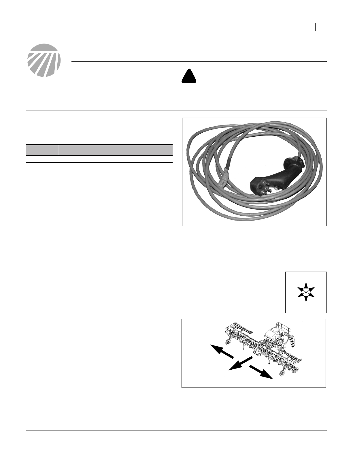
Figure 1
833-510C HHCT
Notations and Conventions
“Left” and “Right” are facing in the
direction of machine travel. An orientation rose in the line art illustrations
shows the directions of Up, Back, Left,
Down, Front, and Right.
R
F
29197
U
B
L
D
Tools Required
• 833-510C HHCT (Hand-Held Calibration Tool)
• 401-312M 3PYP Planter Operator Manual
• 401-312Q 3PYP Planter Pre-Delivery Manual
• The tractor to be used with the planter, having:
300-608 steering console installed, and;
tractor steering sensor installed
R
L
Figure 2
Right / Left
©Copyright 2008 Printed 12/10/2008 401-565M
25050
Page 2

2 EHPR Valve Calibration
Before You Start
Review these instructions, with the following objectives at
each step:
• Need:
EHPR calibration is not a routine task. The normal
Steering Calibration done at post-delivery does not
require the HHCT or these instructions.
Great Plains Mfg., Inc.
Avoid High Pressure Fluids
• Pre-requisites:
ECU must be loaded with valid working firmware. If any
update is needed, perform it prior to EHPR calibration.
• Safety:
Hydraulic Lines may be under pressure even with tractor circuits in Float.
Frame-mountedcoulters have sharp disk blades under
the work area.
• Comprehension:
Make sure the operator understands where involved
components are located, how to use the tools, the
steps involved, and what to expect.
Pre-Calibration Preparation
Work Location
1. If the planter must be moved prior to calibration, plan
the method and route so that only forward moves are
necessary. It is not safe to make reverse moves on
the planter’s caster wheels when either EHPR or
normal Steering Calibration need to be done.
Prepare Planter
2. If a seed hopper or box is mounted, close the slide
gate to prevent seed flow.
3. Fully hitch to suitable tractor or hydraulic source.
Operate the hydraulic source until the oil is warmed
to normal operating temperature.
4. Set tractor steering wheels straight ahead.
5. Hoist, lift or jack up the seed cart so that caster
wheels are off ground.
6. Adjust fan/steering system hydraulic circuit to normal
operating flow.
Escaping fluid under pressure can penetrate the skin,
causing serious injury.
▲ Reduce the hazard by relieving pressure before disconnect-
ing hydraulic lines.
▲ Wear protective gloves and safety glasses or goggles when
working with hydraulic systems.
▲ Assume lines are pressurized until bled. Slowly open
(“crack”) fittings.
▲ Use a piece of paper or cardboard, NOT BODY PARTS, to
check for suspected leaks.
▲ If an accident occurs, seek immediate medical attention
from a physician familiar with this type of injury.
Note: The cart can be lifted off the ground using its own
lift-assist cylinders if the following conditions are
met:
The hitched tractor must have sufficient weight.
The shipping stand is installed on the planter.
The lower 1in pins must be installed in the floating
lug at each lift-assist cylinder rod end. The shear
bolts must be removed. The top link must be left
disconnected at the 3-point hitch.
Calibrate Sensors
7. Perform the Steering Calibration (see Operator Man-
ual 401-312M) at this time. This calibrates the ECU
for the tractor and cart linear displacement sensors.
Sensor calibration must be done before EHPR valve
calibration.
401-565M 12/10/2008
Page 3

Great Plains Mfg., Inc.
EHPR Valve Calibration
Power-Up Steering System
Refer to Figure 3
1. Set the CALIBRATION switch to
center/Off.
3
Calibration Procedure 3
4
5
7
2. Set the STEERING OVERRIDE switch to
down/OFF
3. Set the REVERSE STEER (Power) switch to
Up/ON
4. Confirm that only the power indicator is illumi-
nated.
5. Engage the hydraulic circuit for Fan/Steering.
6. Briefly toggle the STEERING OVERRIDE switch
to Up/ON to confirm:
circuit active
flow direction correct (fan rotation direction)
2
1
4
Connect HHCT
Refer to Figure 4
7. Before connecting the HHCT, set the
Valve Select switch to
Center/OFF.
1
6
3
2
1
Figure 3
Steering Console
2
25242
1
Figure 4
833-510C HHCT Off
Refer to Figure 5
8. At the planter hitch, locate the calibration lead
from the ECU - it is a short (~18in) cable terminated
in a 12-pin plug.
9. Plug the HHCT cable receptacle into the calibration
cable plug.
IMPORTANT !
The calibration system is now live. Do not operate any
HHCT switches or buttons until instructed.
12/10/2008 401-565M
2
2
Figure 5
Calibration Harness at ECU
29197
29212
Page 4

4 EHPR Valve Calibration
Great Plains Mfg., Inc.
Steer-Right EHPR Valve
Refer to Figure 6
10. Activate steer-right calibration by moving the Valve
Select switch to the RIGHT.
11. Momentarily move the Imin Adjust toggle switch
1
2
upwards (increase) direction.
12. Wait a few seconds to detect caster rotation.
You are looking for very slight [slow] movement.
13. If no movement is detected, repeat step 11 until
caster movement is detected. This may require a
considerable number of increases.
14. When movement is detected, and just once, momen-
tarily move the Imin Adjust toggle switch down-
2
ward (decrease) direction.
15. Check for caster movement. If caster continues to
move repeat step 14 until movement stops.
16. Press and release the Learn Button once.
The Learn Acknowledge light should flash.
17. Move the Valve Select switch to the center (off)
3
4
1
position.
Steer-Left EHPR Valve
18. Activate steer-left calibration by moving the Valve
Select switch to the LEFT.
19. Momentarily move the Imin Adjust toggle switch
upwards (increase) direction.
20. Wait a few seconds to detect caster rotation.
You are looking for very slight (slow) movement.
21. If no movement is detected, repeat step 19 until
caster movement is detected. This may require a
considerable number of increases.
22. When movement is detected, and just once, momen-
tarily move the Imin Adjust toggle switch downward (decrease) direction.
23. Check for caster movement. If caster continues to
move repeat step 22 until movement stops.
1
2
2
1
Valve Select:
Left: Steer-Left Valve
Center: Off
Right: Steer-Right Valve
2
Imin Adjust:
Up: Increase Current to Valve
Center: Off
Down: Decrease Current to Valve
3
Learn Button:
Press and release to store Imin
4
Learn Acknowledge:
Light flashes when Imin value stored
5
Rear Wheel Sensor:
Up: Enabled
Down: Disabled
6
Rear Wheel Sensor Light:
If switch is On, light flashes when sensor
5 6
disk rotates
5
2
3
4
6
1
24. Press and release the Learn Button once.
The Learn Acknowledge light should flash.
25. Move the Valve Select switch to the center (off)
3
4
1
position.
Figure 6
29197
833-510C HHCT Controls
401-565M 12/10/2008
Page 5

Great Plains Mfg., Inc.
Confirm System Operation
Leave the fan/steering circuit active for these steps.
26. Disconnect the HHCT from the ECU.
!
CAUTION
Injury Risk:
Be directly ahead or behind, and outside a caster wheel for
step 27 through step 29. At one or more steps the caster wheels
are likely to pivot under hydraulic power to match the current
tractor steering direction. This movement is sudden and forceful, and could knock you down or crush you if you get between
the wheel and nearby planter components.
27. Spin the left caster wheel forward. The fan should
engage, and manual pivoting of the casters should
be possible.
28. Stop the wheel. This may stop the fan. It may or may
not be possible to manually pivot the caster.
29. Spin the left caster wheel backwards. The fan should
stop/not engage. The casters may pivot to match
tractor steering - this could be a small or a large
movement. It should not be possible to manually
pivot the casters, as it they are now under active
hydraulic control.
Calibration Procedure 5
Closeout
30. Set the fan/steering hydraulic circuit control to Float.
31. At the steering console, set the REVERSE STEER
switch OFF (down).
32. Lower the seed cart to the ground.
33. Perform Parking checklist from Operator Manual.
Steering System Operation
See Operator Manual 401-312M.
12/10/2008 401-565M
Page 6

6 EHPR Valve Calibration
Great Plains Mfg., Inc.
Great Plains Manufacturing, Inc.
Corporate Office P.O. Box 5060
Salina, Kansas 67402-5060 USA
401-565M 12/10/2008
 Loading...