

Page 1
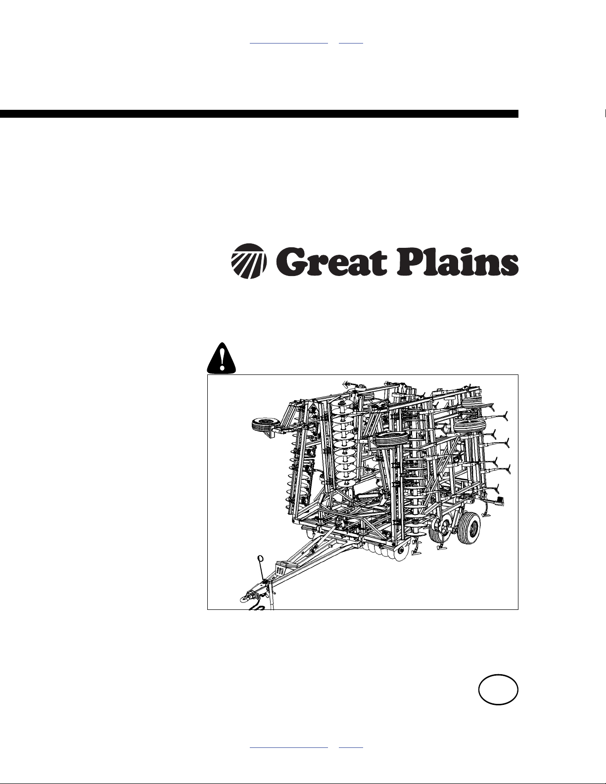
Table of Contents Index
Assembly Manual
Series VIII 8321, 8324, 8326, 8328,
8333, 8537, 8544, 8548 & 8552
Discovator (Disc & Coulter)
Manufacturing, Inc.
www.greatplainsmfg.com
Read the operator’s manual entirely. When you see this symbol, the
subsequent instructions and warnings are serious - follow without
exception. Your life and the lives of others depend on it!
Illustrations may show optional equipment not supplied with standard unit.
41419
ORIGINAL INSTRUCTIONS
© Copyright 2014 Printed 02/12/2014 550-353Q-ENG
Table of Contents Index
EN
Page 2

Table of Contents Index
Table of Contents Index
Page 3

Great Plains Manufacturing, Inc. iii
Table of Contents
Important Safety Information ...................................... 1
Introduction ..................................................................4
Description of Unit ..........................................................4
Models Covered ............................................................. 4
Document Family ...........................................................4
Tools Required ...............................................................4
Pre-assembly Checklist..................................................4
Using This Manual..........................................................5
Definitions................................................................... 5
Shipping Inventory..........................................................6
Unloading ....................................................................... 7
Unpacking Components .............................................7
Unload Smaller Items First .........................................7
Unpacking Boxes .......................................................7
Assembly and Setup Assistance ................................7
Assembly ......................................................................8
Center Brace Bar & Torque Tube............................... 8
Truss & Level Bar.....................................................10
8321-8328, 8537-8544 Center Fold .........................12
8333, 8548-8552 Center Fold ..................................14
Connect Hitch...........................................................16
Install 8321-8324 Wings...........................................18
Install 8321-8324 Wing Fold..................................... 19
Install 8326-8333 Wings...........................................20
Install 8537-8552 Inside Wings ................................22
Install 8537-8552 Wing Fold..................................... 24
Install 8537-8552 Outside Wings..............................26
Install 8537-8552 Outside Wing Fold .......................27
Walking Beam Assembly..............................................27
Install Bearings and Seals........................................27
Install Spindle Sleeves .............................................28
Install Walking Beam................................................28
Install K-Flex............................................................. 29
Install Magnum Shank..............................................29
Gang Hangers ..............................................................30
Install Gang Hangers................................................ 30
Gang Hanger Spring Adjustment..............................30
Install 8321-8537 Gauge Wheel...............................30
Install 8544-8552 Hydraulic Gauge Wheel...............31
Hydraulic Gauge Wheel Spring Adjustment .............31
Install Hydraulic Valves ............................................32
Install Rebound Valve and O-Ring Fittings...............33
Install Depth Control Valve.......................................33
Install Hose Handles.................................................34
Install JIC Fittings.....................................................34
Attach Hose Clamps and Hose wraps ..................... 35
Hydraulic Hose Hookup ........................................... 35
Hose Handles........................................................... 36
Purging Hydraulic System........................................36
Install Gang Assembly ............................................. 38
Straight Gang Depth Indicator Installation ............... 38
Angled Gang Depth Indicator Installation................. 39
Install Depth Guide Decal ........................................ 39
Lights and SMV Assembly ....................................... 40
Rear Hitch Assembly (optional)................................ 42
Completing Setup..................................................... 42
Appendix..................................................................... 43
Torque Values Chart.................................................... 43
Tire Inflation and Warranty........................................... 44
Hydraulic Connectors and Torque ............................... 45
8321-8333 Lift & Gang Layout ..................................... 46
8321-8333 Fold Layout ................................................ 47
8537 Lift & Gang Layout .............................................. 48
8537 Lift & Gang Layout .............................................. 49
8544-8552 Lift & Gang Layout ..................................... 50
8544-8552 Lift & Gang Layout ..................................... 51
8537-8552 Fold Layout ................................................ 52
8537-8552 Fold Layout ................................................ 53
8321D Machine Layout, Disc ....................................... 54
8321C Machine Layout, Coulter .................................. 55
8324D Machine Layout, Disc ....................................... 56
8324C Machine Layout, Coulter .................................. 57
8326D Machine Layout, Disc ....................................... 58
8326C Machine Layout, Coulter .................................. 59
8328D Machine Layout, Disc ....................................... 60
8328C Machine Layout, Coulter .................................. 61
8333D Machine Layout, Disc ....................................... 62
8333C Machine Layout, Coulter .................................. 63
8537D Machine Layout, Disc ....................................... 64
8537D Machine Layout, Disc ....................................... 65
8537C Machine Layout, Coulter .................................. 66
8537C Machine Layout, Coulter .................................. 67
8544D Machine Layout, Disc ....................................... 68
8544D Machine Layout, Disc ....................................... 69
8544C Machine Layout, Coulter .................................. 70
8544C Machine Layout, Coulter .................................. 71
8548D Machine Layout, Disc ....................................... 72
8548D Machine Layout, Disc ....................................... 73
© Copyright 2006, 2007, 2008, 2009, 2010, 2011, 2012, 2013, 2014 All rights Reserved
Great Plains Manufacturing, Inc. provides this publication “as is” without warranty of any kind, either expressed or implied. While every precaution has been
taken in the preparation of this manual, Great Plains Manufacturing, Inc. assumes no responsibility for errors or omissions. Neither is any liability assumed for
damages resulting from the use of the information contained herein. Great Plains Manufacturing, Inc. reserves the right to revise and improve its products as
it sees fit. This publication describes the state of this product at the time of its publication, and may not reflect the product in the future.
02/12/2014 550-353Q-ENG
Trademarks of Great Plains Manufacturing, Inc. include: Singulator Plus, Swath Command, Terra-Tine.
Registered Trademarks of Great Plains Manufacturing, Inc. include:
Air-Pro, Clear-Shot, Discovator, Great Plains, Land Pride, MeterCone, Nutri-Pro, Seed-Lok, Solid Stand,
Terra-Guard, Turbo-Chisel, Turbo-Chopper, Turbo Max, Turbo-Till, Ultra-Till, Verti-Till, Whirlfilter, Yield-Pro.
Brand and Product Names that appear and are owned by others are trademarks of their respective owners.
Printed in the United States of America
Page 4

iv8321-8552DV Great Plains Manufacturing, Inc.
8548C Machine Layout, Coulter .................................. 74
8548C Machine Layout, Coulter .................................. 75
8552D Machine Layout, Disc ....................................... 76
8552D Machine Layout, Disc ....................................... 77
8552C Machine Layout, Coulter .................................. 78
8552C Machine Layout, Coulter .................................. 79
8321DV HD 3 Bar Spike W/Reel ................................. 80
8321DV S7T Spike Drag.............................................. 81
8321DV S5T HR Spike Drag ....................................... 82
8321DV CH4B Coil Tine .............................................. 83
8324DV HD 3 Bar Spike W/Reel ................................. 84
8324DV S7T Spike Drag.............................................. 85
8324DV S5T HR Spike Drag ....................................... 86
8324DV CH4B Coil Tine .............................................. 87
8326DV HD 3 Bar Spike W/Reel ................................. 88
8326DV S7T Spike Drag.............................................. 89
8326DV S5T HR Spike Drag ....................................... 90
8326DV CH4B Coil Tine .............................................. 91
8328DV HD 3 Bar Spike W/Reel ................................. 92
8328DV S7T Spike Drag.............................................. 93
8328DV S5T HR Spike Drag ....................................... 94
8328DV CH4B Coil Tine .............................................. 95
8333DV HD 3 Bar Spike W/Reel ................................. 96
8333DV S7T Spike Drag.............................................. 97
8333DV S5T HR Spike Drag ....................................... 98
8333DV CH4B Coil Tine .............................................. 99
8537DV HD 3 Bar Spike W/Reel ............................... 100
8537DV HD 3 Bar Spike W/Reel ............................... 101
8537DV S7T Spike Drag............................................ 102
8537DV S7T Spike Drag............................................ 103
8537DV S5T HR Spike Drag ......................................104
8537DV S5T HR Spike Drag ......................................105
8537DV CH4B Coil Tine.............................................106
8537DV CH4B Coil Tine.............................................107
8544DV HD 3 Bar Spike W/Reel ................................108
8544DV HD 3 Bar Spike W/Reel ................................109
8544DV S7T Spike Drag ............................................110
8544DV S7T Spike Drag ............................................111
8544DV S5T HR Spike Drag ......................................112
8544DV S5T HR Spike Drag ......................................113
8544DV CH4B Coil Tine.............................................114
8544DV CH4B Coil Tine.............................................115
8548DV HD 3 Bar Spike W/Reel ................................116
8548DV HD 3 Bar Spike W/Reel ................................117
8548DV S7T Spike Drag ............................................118
8548DV S7T Spike Drag ............................................119
8548DV S5T HR Spike Drag ......................................120
8548DV S5T HR Spike Drag ......................................121
8548DV CH4B Coil Tine.............................................122
8548DV CH4B Coil Tine.............................................123
8552DV HD 3 Bar Spike W/Reel ................................124
8552DV HD 3 Bar Spike W/Reel ................................125
8552DV S7T Spike Drag ............................................126
8552DV S7T Spike Drag ............................................127
8552DV S5T HR Spike Drag ......................................128
8552DV S5T HR Spike Drag ......................................129
8552DV CH4B Coil Tine.............................................130
8552DV CH4B Coil Tine.............................................131
Index ..........................................................................133
550-353Q-ENG 02/12/2014
Page 5
Great Plains Manufacturing, Inc. 1
Important Safety Information
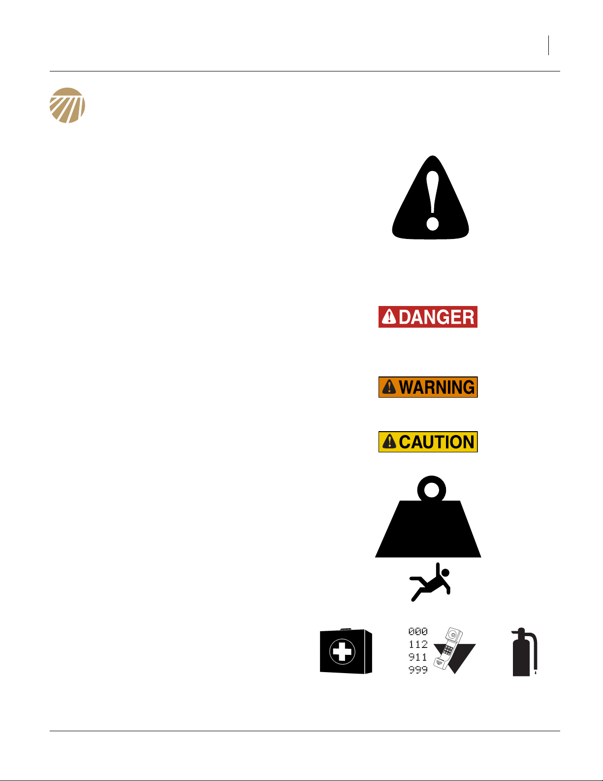
Look for Safety Symbol
The SAFETY ALERT SYMBOL indicates there is a
potential hazard to personal safety involved and extra
safety precaution must be taken. When you see this
symbol, be alert and carefully read the message that follows it. In addition to design and configuration of equipment, hazard control and accident prevention are
dependent upon the awareness, concern, prudence and
proper training of personnel involved in the operation,
transport, maintenance and storage of equipment.
Be Aware of Signal Words
Signal words designate a degree or level of hazard seriousness.
DANGER indicates an imminently hazardous situation
which, if not avoided, will result in death or serious injury.
This signal word is limited to the most extreme situations,
typically for machine components that, for functional purposes, cannot be guarded.
WARNING indicates a potentially hazardous situation
which, if not avoided, could result in death or serious
injury, and includes hazards that are exposed when
guards are removed. It may also be used to alert against
unsafe practices.
CAUTION indicates a potentially hazardous situation
which, if not avoided, may result in minor or moderate
injury. It may also be used to alert against unsafe practices.
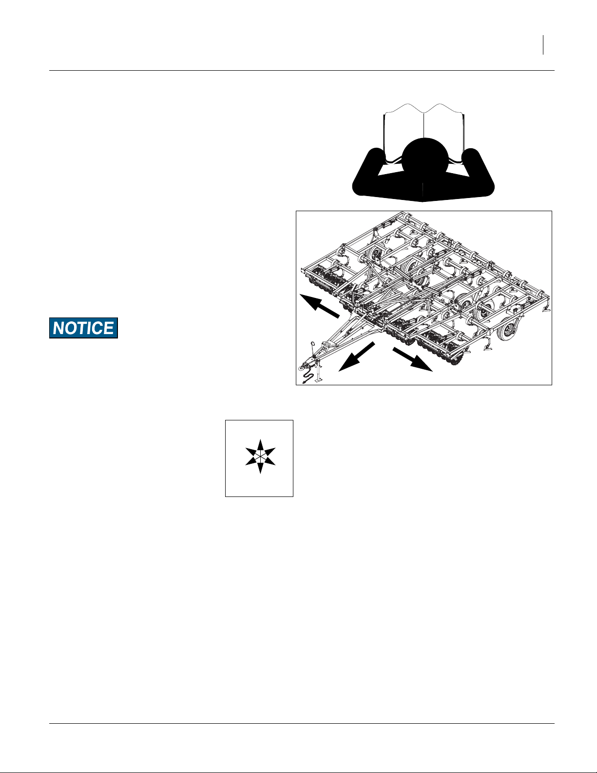
Use Adequate Lifting Means
The frame sections and gangs of this machine are
extremely heavy. If using multiple lifters, make sure each
is rated for at least its share of the load.
> 14,000
POUNDS
Prepare for Emergencies
▲ Be prepared if a fire starts
▲ Keep a first aid kit and fire extinguisher handy.
▲ Keep emergency numbers for doctor, ambulance, hospital
and fire department near phone.
02/12/2014 550-353Q-ENG
Page 6
2 8321-8552DV Great Plains Manufacturing, Inc.
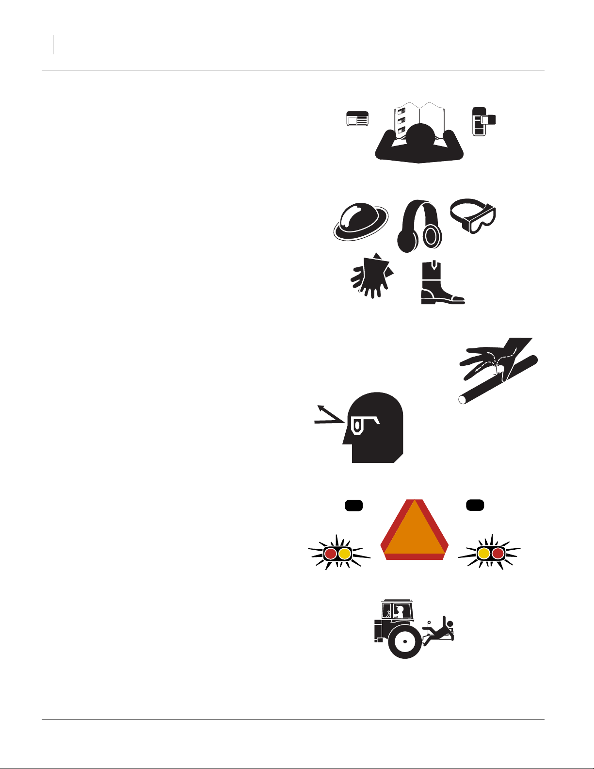
Be Familiar with Safety Decals
▲ Read and understand the “Safety Decals” section of the
Operators Manual.
▲ Read all instructions noted on the decals.
▲ Keep decals clean. Replace damaged, faded and illegible
decals.
Wear Protective Equipment
▲ Wear protective clothing and equipment.
▲ Wear clothing and equipment appropriate for the job. Avoid
loose-fitting clothing.
▲ Because prolonged exposure to loud noise can cause hear-
ing impairment or hearing loss, wear suitable hearing protection such as earmuffs or earplugs.
▲ Because operating equipment safely requires your full
attention, avoid wearing entertainment headphones while
operating machinery.
Avoid High Pressure Fluids
Escaping fluid under pressure can penetrate the skin,
causing serious injury.
▲ Avoid the hazard by relieving pressure before disconnecting
hydraulic lines.
▲ Use a piece of paper or cardboard, NOT BODY PARTS, to
check for suspected leaks.
▲ Wear protective gloves and safety glasses or goggles when
working with hydraulic systems.
▲ If an accident occurs, seek immediate medical assistance
from a physician familiar with this type of injury.
Use Safety Lights and Devices
Slow-moving tractors and towed implements can create
a hazard when driven on public roads. They are difficult
to see, especially at night.
▲ Use flashing warning lights and turn signals whenever driv-
ing on public roads.
Use lights and devices provided with implement
Keep Riders Off Machinery
Riders obstruct the operator’s view. Riders could be
struck by foreign objects or thrown from the machine.
▲ Never allow children to operate equipment.
▲ Keep all bystanders away from machine during operation.
550-353Q-ENG 02/12/2014
Page 7
Great Plains Manufacturing, Inc. Important Safety Information 3
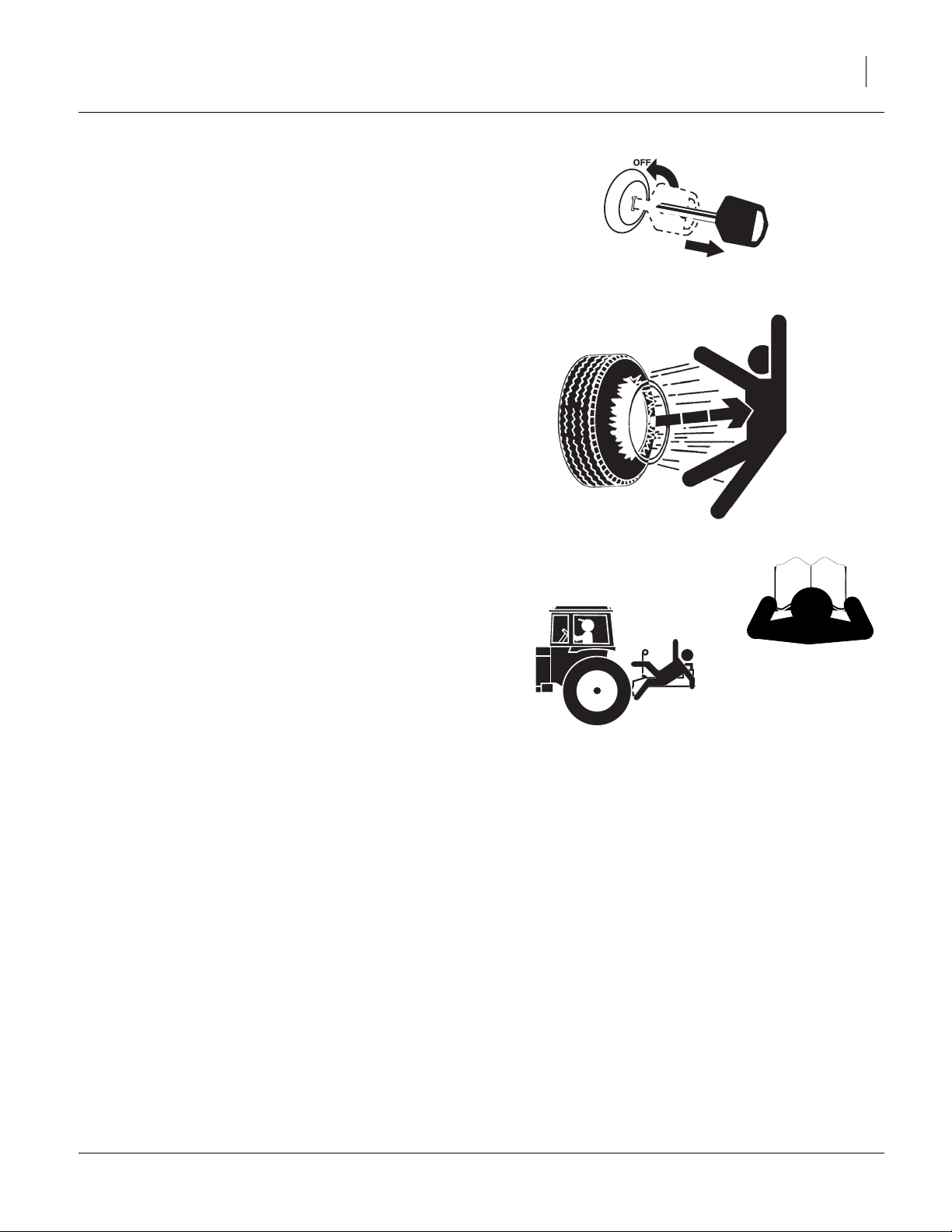
Shutdown and Storage
▲ Lower implement, put tractor in park, turn off engine, and
remove the key.
▲ Secure Discovator using blocks and supports provided.
▲ Detach and store Discovator in an area where children nor-
mally do not play.
Tire Safety
Tire changing can be dangerous and should be performed by trained personnel using correct tools and
equipment.
▲ When inflating tires, use a clip-on chuck and extension hose
long enough for you to stand to one side–not in front of or
over tire assembly. Use a safety cage if available.
▲ When removing and installing wheels, use wheel-handling
equipment adequate for weight involved.
Safety At All Times
Thoroughly read and understand the instructions in this
manual before operation. Read all instructions noted on
the safety decals.
▲ Be familiar with all machine functions.
▲ Operate machinery from the driver’s seat only.
▲ Do not leave machine unattended with tractor engine run-
ning.
▲ Do not stand between the tractor and machine during
hitching.
▲ Keep hands, feet and clothing away from power-driven
parts.
▲ Wear snug-fitting clothing to avoid entanglement with mov-
ing parts.
▲ Watch out for wires, trees, etc., when folding and raising
machine. Make sure all persons are clear of working area.
02/12/2014 550-353Q-ENG
Page 8

4 8321-8552DV Great Plains Manufacturing, Inc.
Introduction
The Discovator has been designed with care and built by
skilled workers using quality materials. Proper setup,
maintenance, and safe operating practices will help the
customer get years of satisfactory use from the machine.
Description of Unit
The Series VIII, 8321-8552DV Discovator is a three or
five-section field finishing, one-pass tillage tool. Working
width ranges from 21 to 52 feet. The implement is
designed to combine discing/slicing, cultivating, harrowing and herbicide incorporation in a single pass. Various
finishing attachments are available to customize your tillage and residue requirements for your operation
Models Covered
8321DV 21-Foot 3-section
8324DV 24-Foot 3-section
8326DV 26-Foot 3-section
8328DV 28-Foot 3-section
8333DV 33-Foot 3-section
8537DV 37-Foot 5-section
8544DV 44-Foot 5-section
8548DV 48-Foot 5-section
8552DV 52-Foot 5-section
Document Family
550-353Q-ENG Assembly Manual (this document)
550-353Q Pre-Delivery Manual
550-353M Operator Manual
550-353P Parts Manual
Tools Required
• Basic Hand Tools
• Torque Wrench
• Fork Truck, Overhead Hoist or Loader
Figure 1
Discovator
41645
Pre-assembly Checklist
1. Before assembling, read and understand “Important
Safety Information” in front part of this manual.
2. Have at least two people on hand while assembling.
550-353Q-ENG 02/12/2014
3. Make sure area is level and free of obstructions
(preferably an open concrete area).
4. Have all major components
5. Have all fasteners and pins shipped with Discovator.
Page 9
Great Plains Manufacturing, Inc. Introduction 5
Using This Manual
This manual was written to help you assemble and prepare the new machine for the customer. The manual
includes instructions for assembly and setup. Read this
manual and follow the recommendations for safe, efficient and proper assembly and setup.
An operator’s and parts manual is also provided with the
new machine. Read and understand “Important Safety
Information” and “Operating Instructions” in the operator’s manual before assembling the machine. Refer to
the parts manual for proper part’s identification. As a reference, keep the operator’s and part’s manual on hand
while assembling.
The information in this manual is current at printing.
Some parts may change to assure top performance.
Definitions
The following terms are used throughout this manual.
A crucial point of information related to the preceding topic.
Read and follow the directions to remain safe, avoid serious
damage to equipment and ensure desired field results.
Note: Useful information related to the preceding topic.
Right-hand and left-hand as used in
this manual are determined by facing
the direction the machine will travel
while in use unless otherwise stated.
An orientation rose in some line art
illustrations shows the directions of: Up,
Back, Left, Down, Front, Right
R
F
U
B
L
D
R
L
Figure 2
Right / Left
41542
02/12/2014 550-353Q-ENG
Page 10
6 8321-8552DV Great Plains Manufacturing, Inc.
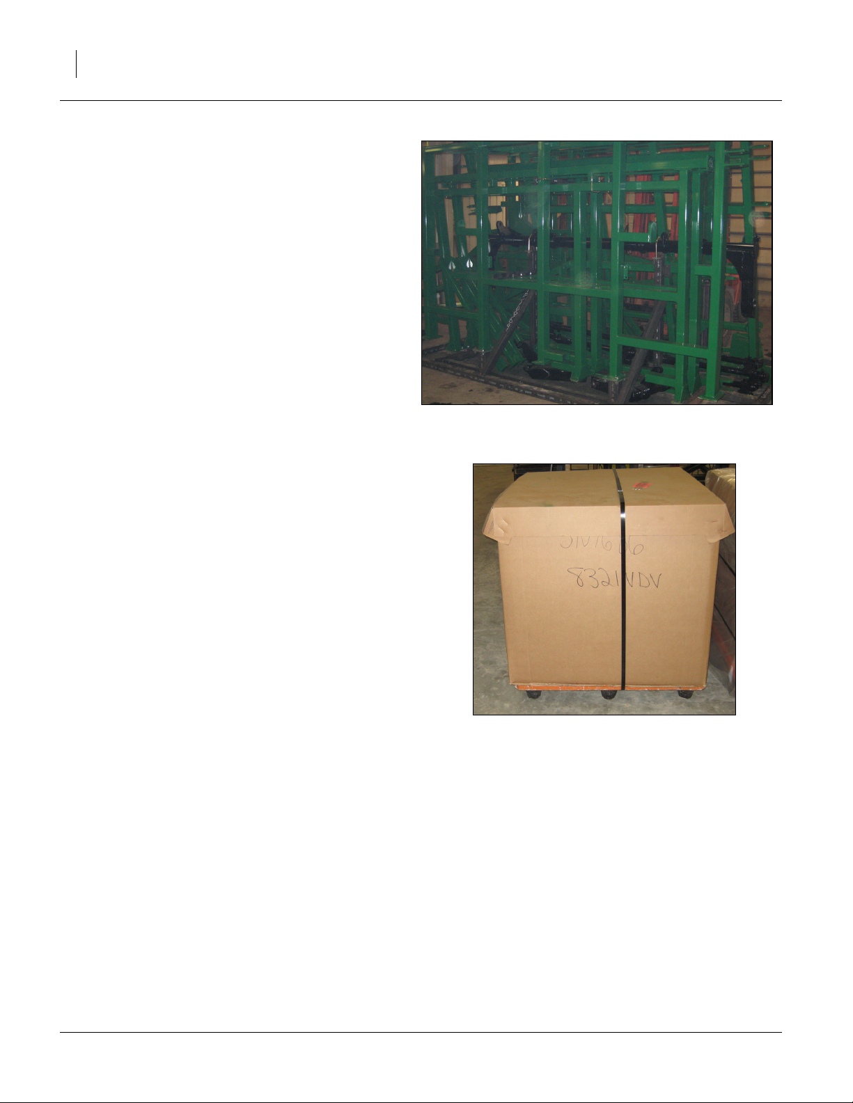
Shipping Inventory
The discovator will be shipped unassembled as shown
in a big shipping rack and shipping boxes on pallets.
The only parts that will be assembled are the disc or
coulter gang assemblies and reel attachment assemblies. The reel attachments (if equipped) will be banded
together with the gang assemblies on pallet.
Refer to Figure 3
• All frame sections, hitch and torque tubes will be
shipped in shipping container.
Refer to Figure 4
• Shank parts, small parts and bolts will be shipped in
boxes. Rear attachment big parts will be banded to
attachment smaller parts box.
Shipping containers do not need to be returned to Great
Plains.
Figure 3
Shipping Rack
Figure 4
Shipping Boxes
41647
41621
550-353Q-ENG 02/12/2014
Page 11

Great Plains Manufacturing, Inc. Introduction 7
Unloading
Once everything is unloaded from “storage pod” you may
proceed with taking parts out of shipping containers.
Carefully move everything to level site and prepare to un
pack items.
Unpacking Components
Be sure you have read and understood the Important
Safety Information, starting on page 1 of this manual,
before you start unpacking componets.
Centering componets:
Be sure and center fork truck or chains (overhead hoist)
on componets so they won’t slide and cause injury.
Carefully un-band componets.
Now unload individual componets one at a time using a
fork truck or overhead hoist.
Move each component out of the way so you have plenty
of room to remove the next one.
Unload Smaller Items First
Unloading the frames is a potentially dangerous operation.
Reduce risk and complication by first unloading
1. the tire wheel assemblies,
2. the smaller items
Place these components well out of the maneuvering
area needed for unloading the gang assemblies and
frames.
3. Carefully unload the Frames and hitch out of shipping rack
Unpacking Boxes
1. Carefully remove banding and lids from boxes.
2. Locate and identify all componets before assembling.
Assembly and Setup Assistance
To order additional copies of pre-delivery instructions or
operator’s and parts manuals, write to the following
address. Include model numbers in all correspondence.
If you do not understand any part of this manual or have
the assembly or setup questions, assistance is available.
Contact:
Product Support
Great Plains Mfg. Inc., Service Department
PO Box 5060
Salina, KS 67402-5060
(800)255-9215
02/12/2014 550-353Q-ENG
Page 12

8 8321-8552DV Great Plains Manufacturing, Inc.
Assembly
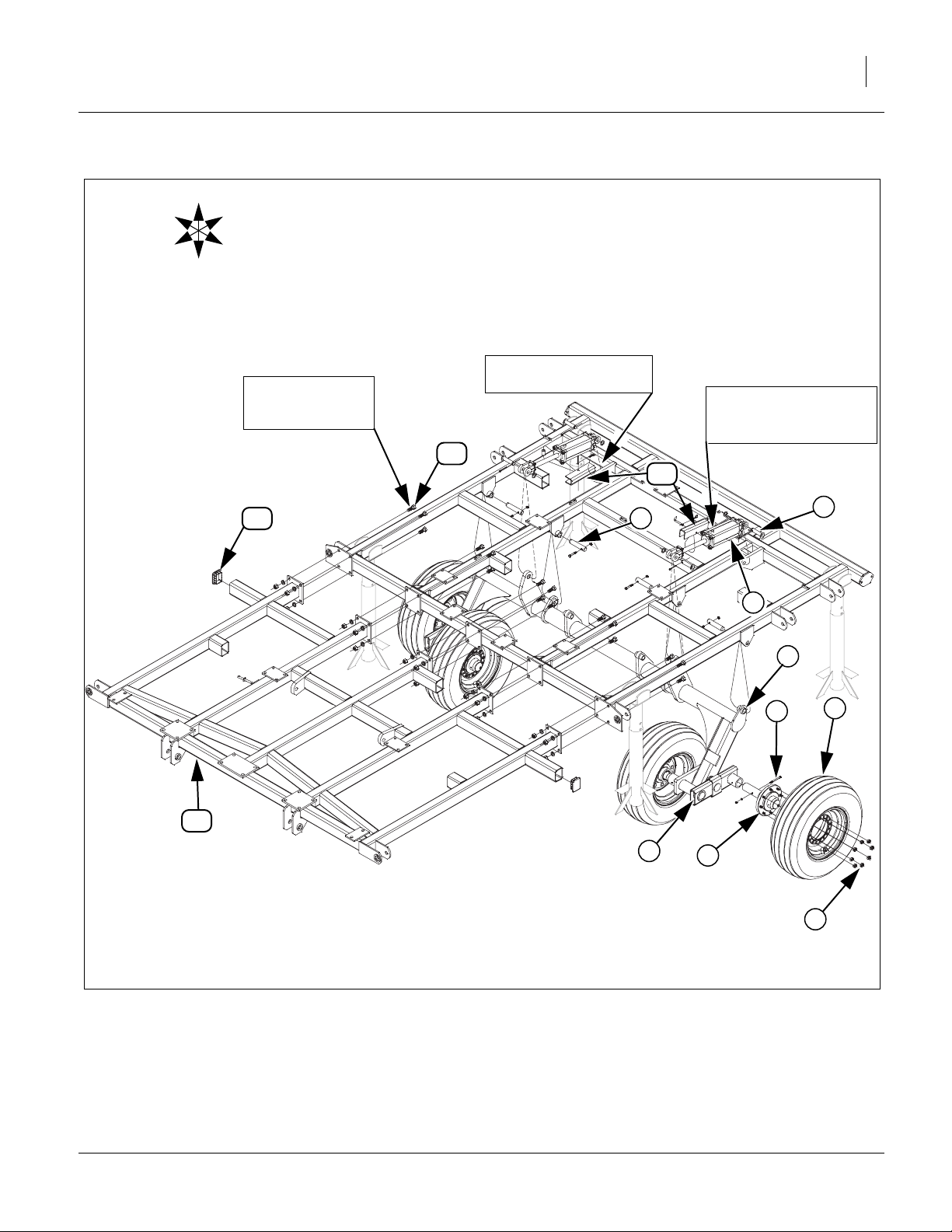
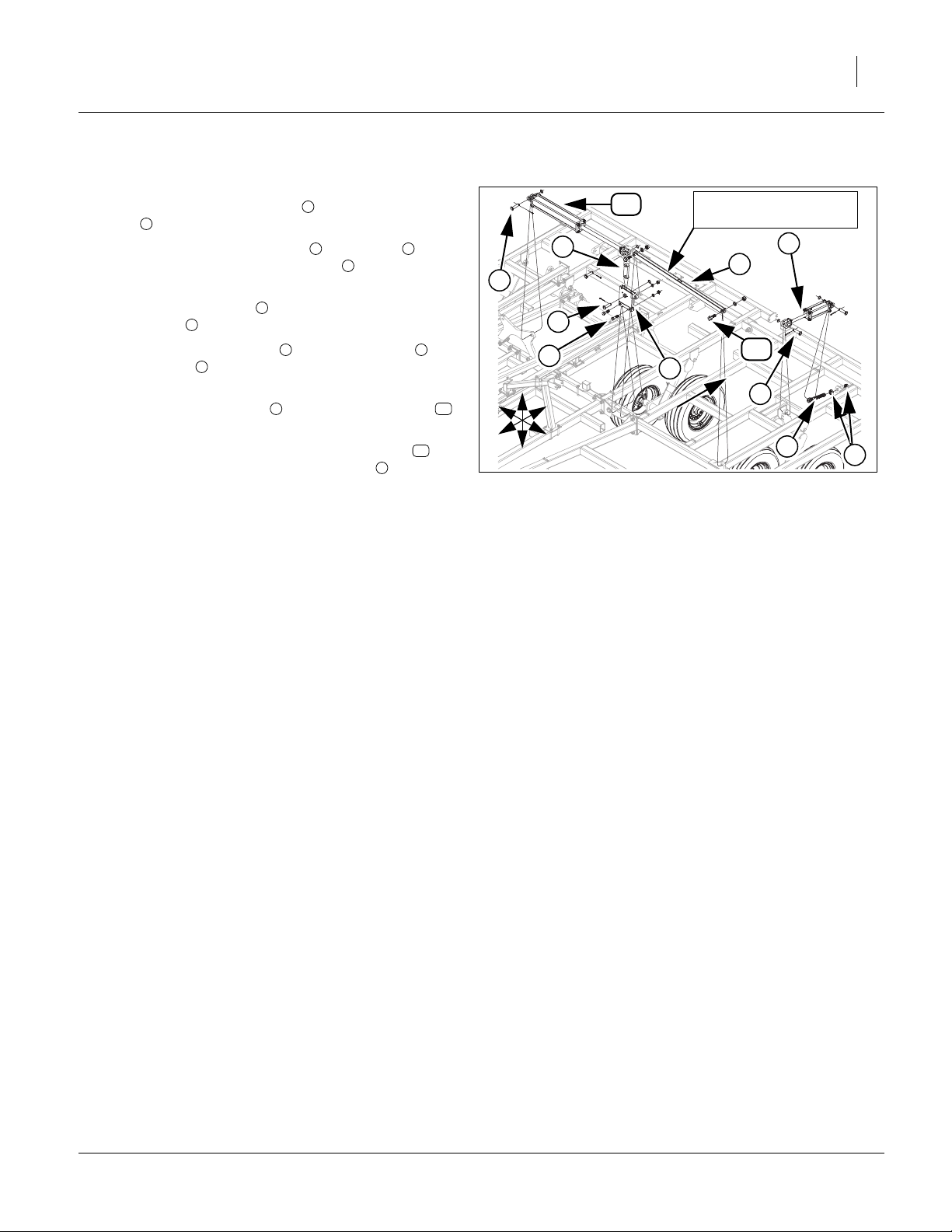
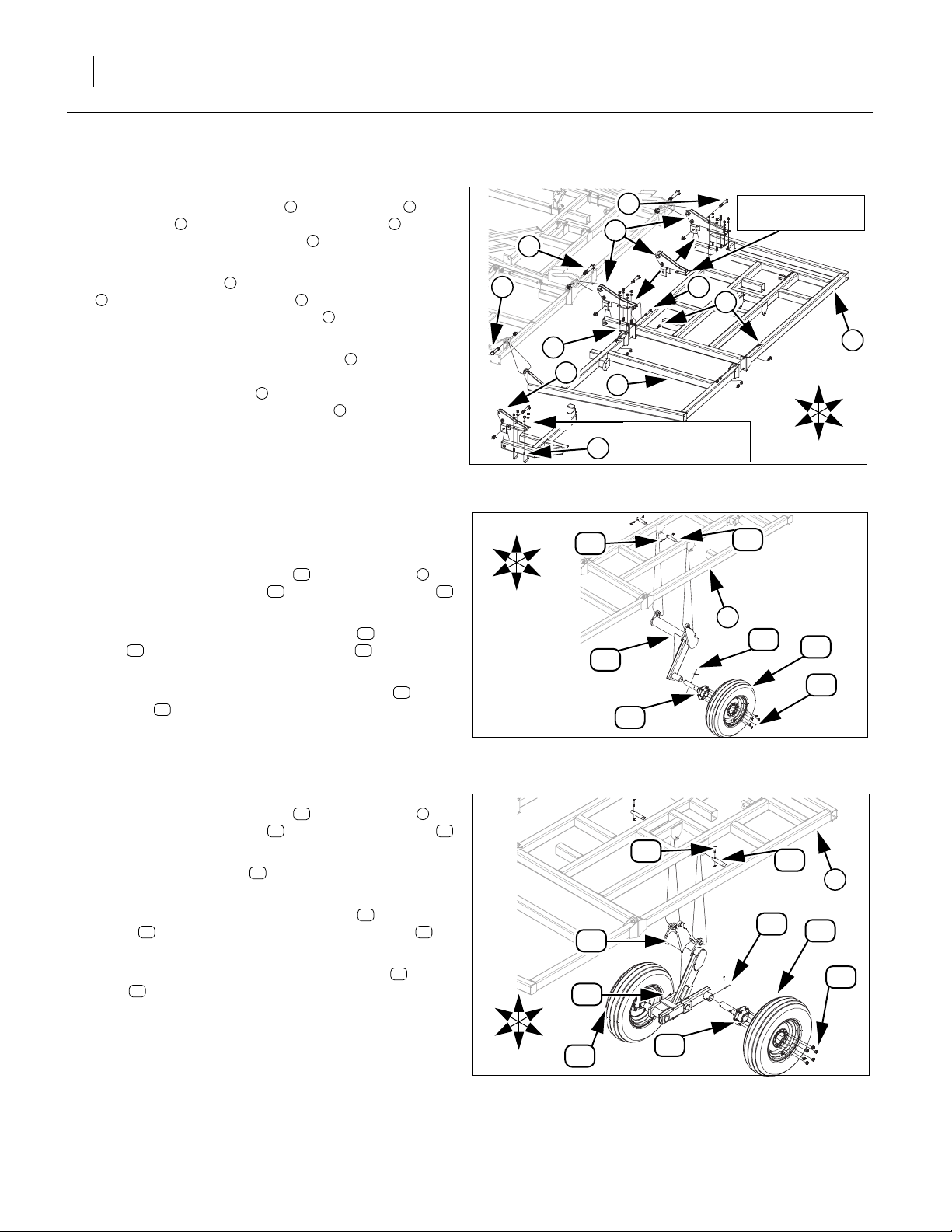
Center Brace Bar & Torque Tube
Refer to Figure 5
1. Once the center Frame has been uncrated and put
on stands, the torque tube maybe installed.
2. Carefully raise the torque tube with an overhead
hoist and secure with 1 1/4 x 6 pins , 3/8 x 2 1/4 Gr.
1
2
8 hex bolts and 3/8 top lock nut.
3. Install walking beams , See “Walking Beam
3
Assembly” on page 27
4. Install pre-assembled hub assembly using 5/16 x
4
4 bolts (models 8321-8537) or 1/2 x 4 1/2 bolts
(models 8544-8552) , secure with 1/2 lock washer
5
and 1/2 nut.
5. Attach the tire/wheel assemblies to hub assembly
and secure with lug nuts .
4 7
6
6. Now install the appropriate cylinders , see hydrau-
8
lics section of “Parts Manual” for correct size, using 1
x 3 11/16 pins , 1.5 x 1.0 x.075 machine washers
9
and 3/16 x 2 cotter pins.
7. Install cylinder transport locks to cylinders
10 8
using the 3/8 x 3 pins and clip pin.
Note: Install 3/4 x 2 Gr. 5 hex bolts , back to front as
12
shown.
8. Carefully move center brace bar into position with
11
fork truck or overhead hoist. Secure with 3/4 x 2 Gr.
5 hex bolts , 3/4 lock washers and 3/4 hex nuts.
12
9. All bolts may be tightened to specs, See “Torque
Values Chart” on page 43. Attach plastic end caps
to all open ends of 4 x 3 tube.
13
550-353Q-ENG 02/12/2014
Page 13
Great Plains Manufacturing, Inc. Assembly 9
U
R
B
F
L
D
Cylinder Transport Lock
Install Bolts from
Back to Front
as Shown
Shown in Field Position
Cylinder Transport Lock
Shown in Transport
Position
12
10
13
2
9
8
1
11
Figure 5
Center Brace Bar & Torque Tube
5
3
4
6
7
41648
02/12/2014 550-353Q-ENG
Page 14

10 8321-8552DV Great Plains Manufacturing, Inc.
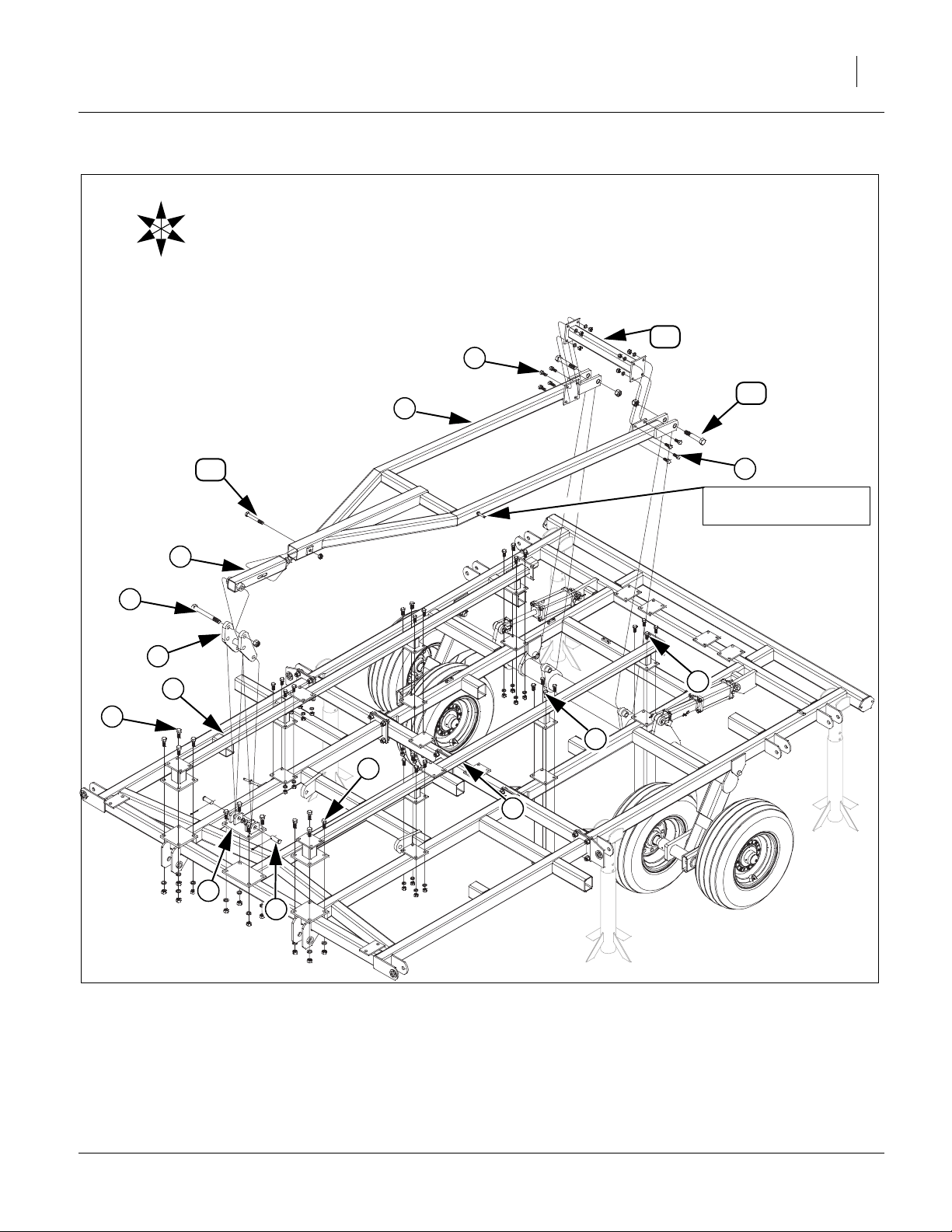
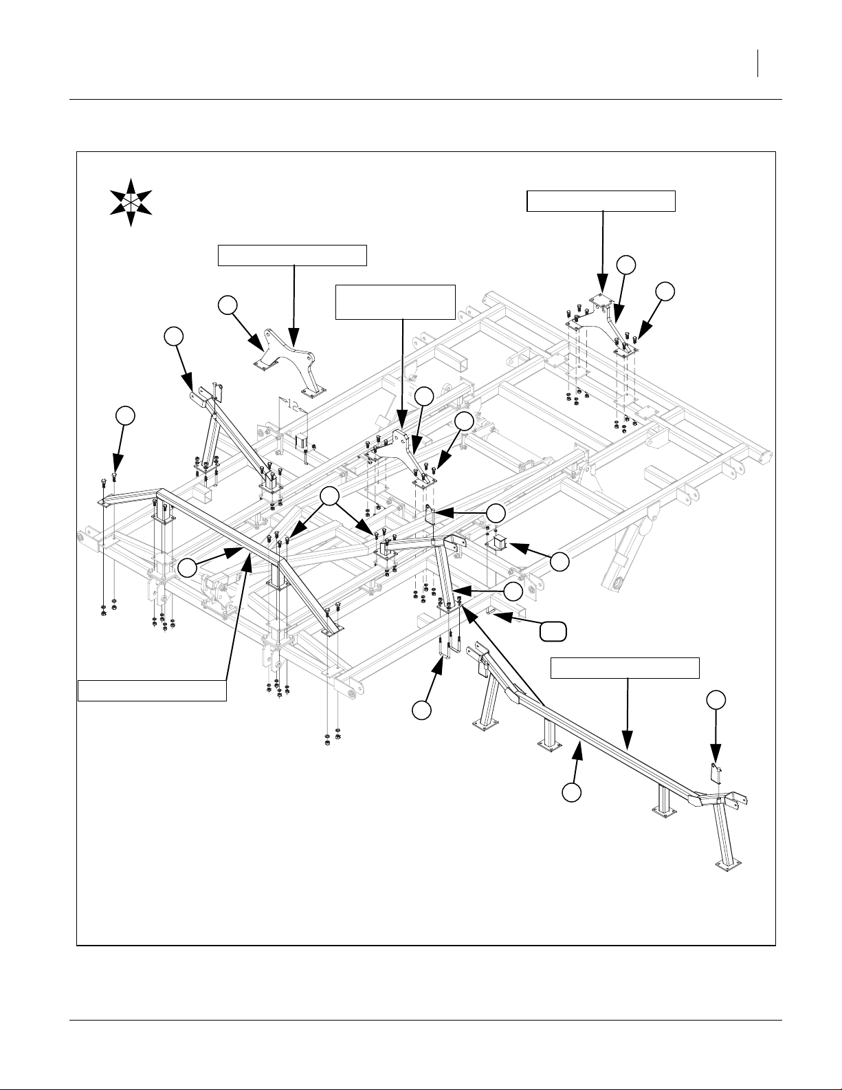
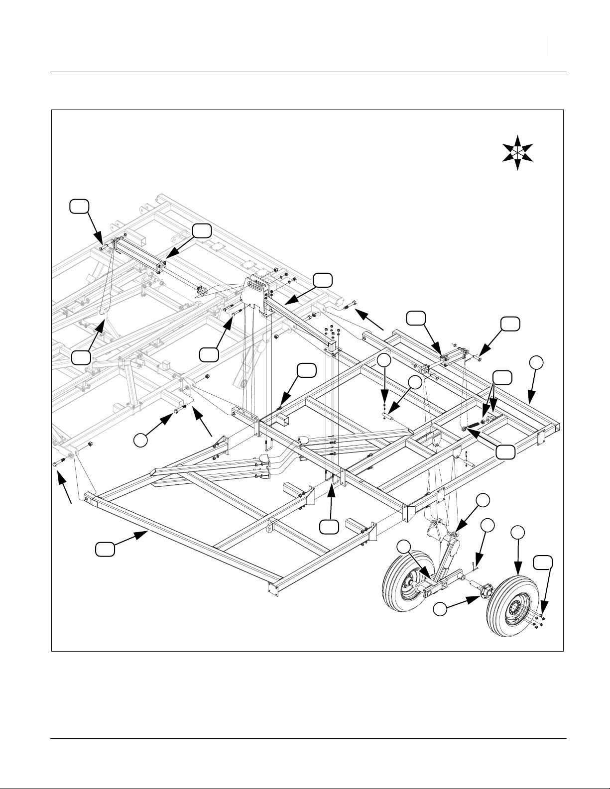
Truss & Level Bar
Refer to Figure 6
10. Now the center frame trusses may be installed
using 5/8 x 1 1/2 Gr. 5 hex bolts , secure with 5/8
1
2
lock washers, 5/8 hex nuts and 3/4 x 2 Gr. 5 hex
bolts , secure with 3/4 lock washers and lock nuts.
3
11. Attach the h-bracket mounting plate with 3/4 x 2
Gr. 5 hex bolts , secure with 3/4 lock washers and
3
4
lock nuts
12. Mount the bottom side of the h-bracket using the 1
x 2 29/64 pins , 1.5 x 1.0 x.075 machine washers
6
5
and 3/16 x 2 cotter pins.
13. Attach the level bar slide tube assembly into the
top side of the h-bracket , secure with 1 x 9 Gr. 8
hex bolt and 1 nylon lock nut.
8
5
7
Note: Install level bar with depth stop tube pin to left
9
side of machine.
14. Now slide the front of the level bar over the back
side of the level bar slide tube assembly , secure
with a 3/4 x 5 1/2 Gr. 5 hex bolt and 3/4 nylock
9
7
10
nut.
15. Attach rear of level bar to the torque tube with the
1 x 6 Gr. 8 special hex bolt and 1 nylon lock nut.
16. Mount the level bar cross tube to the level bar
side plates with 5/8 x 1 1/2 Gr. 5 hex bolts , secure
9
11
12 9
2
with 5/8 lock washers and 5/8 nuts.
17. All bolts may be tightened to specs, See “Torque
Values Chart” on page 43.
550-353Q-ENG 02/12/2014
Page 15
Great Plains Manufacturing, Inc. Assembly 11
U
R
B
F
L
D
12
2
11
9
10
2
Be Sure to Install Depth
Stop Mount on Left Side
7
8
5
1
2
3
2
2
1
4
6
Figure 6
Truss & Level Bar Assembly
02/12/2014 550-353Q-ENG
41649
Page 16

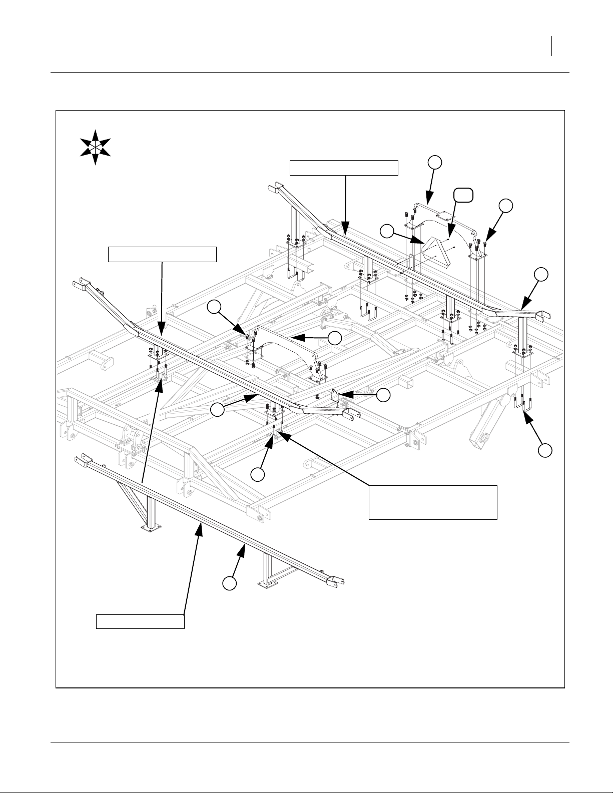
12 8321-8552DV Great Plains Manufacturing, Inc.
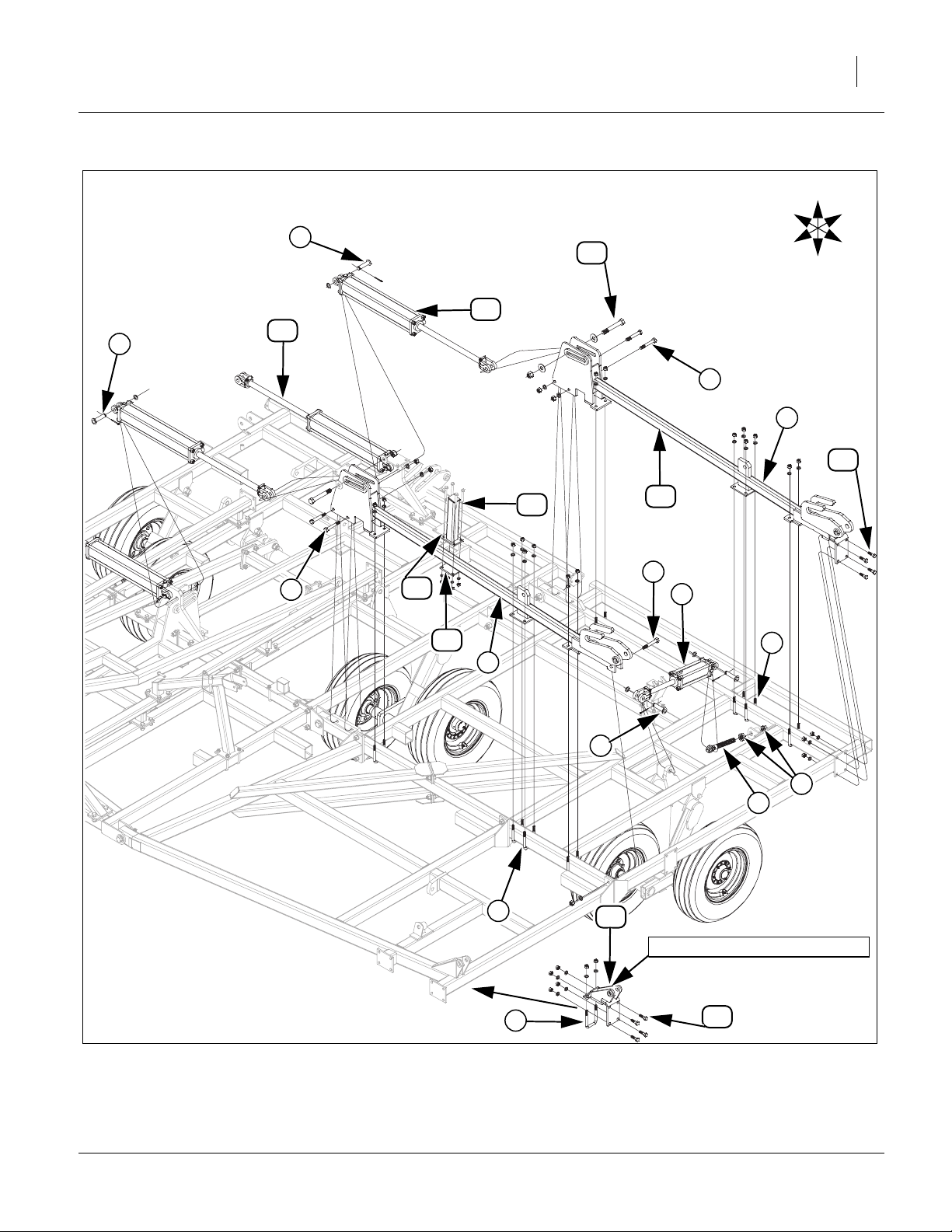
8321-8328, 8537-8544 Center Fold
Refer to Figure 7
18. Attach brace bar truss (models 8537 & 8544) to
1
front of center brace bar, outside plates with 3/4 x 2
, 3/4 lock washers and 3/4 nuts, inside plates with
2
5/8 x 1 1/2 bolts , 5/8 lock washers and nuts.
19. Mount front and rear fold brackets to center
frame with 5/8 x 1 1/2 bolts , 5/8 lock washers and
5
3 4
5
nuts.
20. Attach inside plate of center wing stop , using 5/8 x
1 1/2 bolts , 5/8 lock washers and nuts.
5
21. Attach outside plate of center wing stop , with 5/8 x
3 1/32 x 5 1/2 u-bolts , 5/8 lock washers and nuts.
7
6
6
22. Insert the 1/2 x 4 1/2 pin w/keepers into round
tubes on rear of wing stop .
23. Mount cylinder rest pads , (Models 8321-8324
6
9
8
only) to center frame, with 1/2 x 3 1/32 x 5 u-bolts ,
1/2 lock washers and 1/2 nuts.
Note: Position cylinder rest pad 12” from inside of
9
outer tube to plate on pad as shown.
24. All bolts may be tightened to specs, See “Torque
Values Chart” on page 43.
10
550-353Q-ENG 02/12/2014
Page 17
Great Plains Manufacturing, Inc. Assembly 13
U
R
F
B
Models 8537-8544 Only
L
D
Models 8321-8324 Only
4
6
2
1
Models 8537-8544 Only
3
Models 8326-8328,
8537-8544 Only
5
3
5
5
8
9
6
10
Models 8323-8328 Only
7
8
6
Figure 7
8321-8328, 8537-8544 Center Fold
02/12/2014 550-353Q-ENG
41650
Page 18

14 8321-8552DV Great Plains Manufacturing, Inc.
8333, 8548-8552 Center Fold
Refer to Figure 8
25. Mount front and rear fold brackets to center
frame with 5/8 x 1 1/2 bolts , 5/8 lock washers and
1 2
3
nuts.
26. Attach plates of front wing stop , with 5/8 x 3 1/32 x
4 1/2 u-bolts , 5/8 lock washers and nuts. Position
5
4
plates of wing stop over truss mounting tube as
shown.
27. Insert the 1/2 x 4 1/2 pin w/keepers into round
tubes on rear of wing stop .
4
6
28. Attach rear wing stop on center frame tubes as
shown, with 5/8 x 3 1/32 x 5 1/2 u-bolts , 5/8 lock
7
8
washers and nuts.
29. Mount the SMV sign to wing stop, with 1/4 x 3/4
pan head screws , 1/4 lock washers and 1/4 nuts.
9
10
30. All bolts may be tightened to specs, See “Torque
Values Chart” on page 43.
550-353Q-ENG 02/12/2014
Page 19
Great Plains Manufacturing, Inc. Assembly 15
U
R
B
F
D
L
Models 8548-8552 Only
2
10
3
9
Models 8548-8552 Only
7
3
1
6
4
Models 8333 Only
5
4
Figure 8
8333, 8548-8552 Center Fold
8
Position Wing Stop with One
U-Bolt on each Side of Truss
Mounting Tube
42327
02/12/2014 550-353Q-ENG
Page 20

16 8321-8552DV Great Plains Manufacturing, Inc.
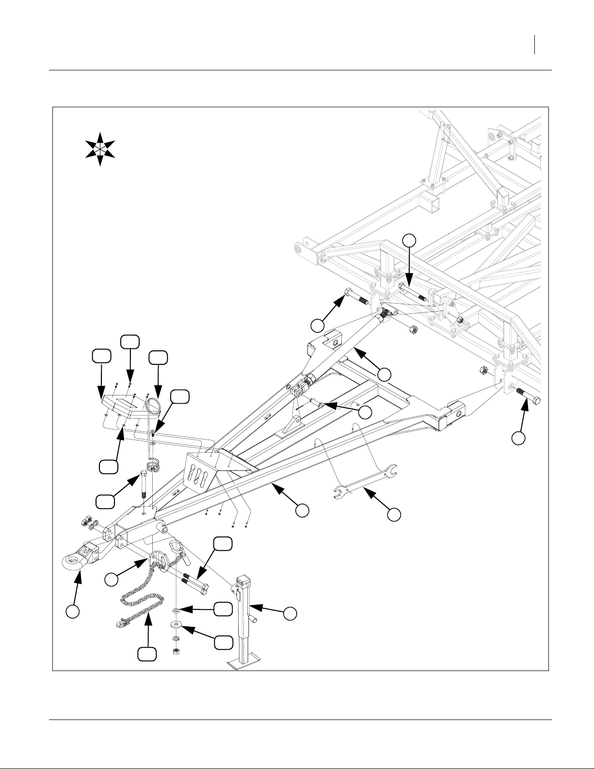
Connect Hitch
Refer to Figure 9
31. Attach hitch to center brace bar using 1 1/4 x 7 Gr.
8 hex bolt and top lock nut.
32. Mount square jack to front mount on hitch with
1
2
3 1
pin provided with jack.
• Use jack to help support front of hitch for rest of hitch
assembly.
33. Attach rear of turnbuckle assembly to h-bracket
with 1 x 9 Gr. 8 hex bolt and 1 nylon lock nut.
5
34. Attach front of turnbuckle assembly to hitch
using 1 x 3 3/8 pin , 1.5 x 1.0 x.075 machine
6
4
4 1
washer and 3/16 x 2 cotter pin.
35. Slip holes in turnbuckle wrench over pegs on
inside (left) side of hitch .
36. Align holes in hitch base with holes in front of hitch
.
1
1
8
7
37. Align holes in safety chain support with holes on
left side of hitch , secure with 1 x 8 Gr. 8 special
hex bolts , 1 lock washers and 1 nut.
10
38. Install safety chain on bottom side of hitch ,
1
12 1
secure with 1 x 7 Gr. 8 hex bolt , 1 3/4od x 1 1/32
id x 1/2 round tube , fold roller , 1 lock washer
13 14
9
11
and 1 nut.
39. Route safety chain through safety chain support
.
9
40. Mount spring hose loop to top side of hitch ,
with 1/2 x 1 1/2 bolt , 1/2 flat washer, 1/2 lock
12
15 1
16
washer and 1/2 nut.
41. Mount the manual pack to hitch with 1/4 x 3/4
pan screws , rubber spacers , 1/4 lock washers
18 19
17 1
and 1/4 nuts.
42. All bolts may be tightened to specs, See “Torque
Values Chart” on page 43.
550-353Q-ENG 02/12/2014
Page 21
Great Plains Manufacturing, Inc. Assembly 17
U
R
B
F
L
D
5
2
18
17
15
4
16
6
2
19
11
1
7
10
9
8
13
3
14
12
Figure 9
Hitch Assembly
02/12/2014 550-353Q-ENG
41651
Page 22
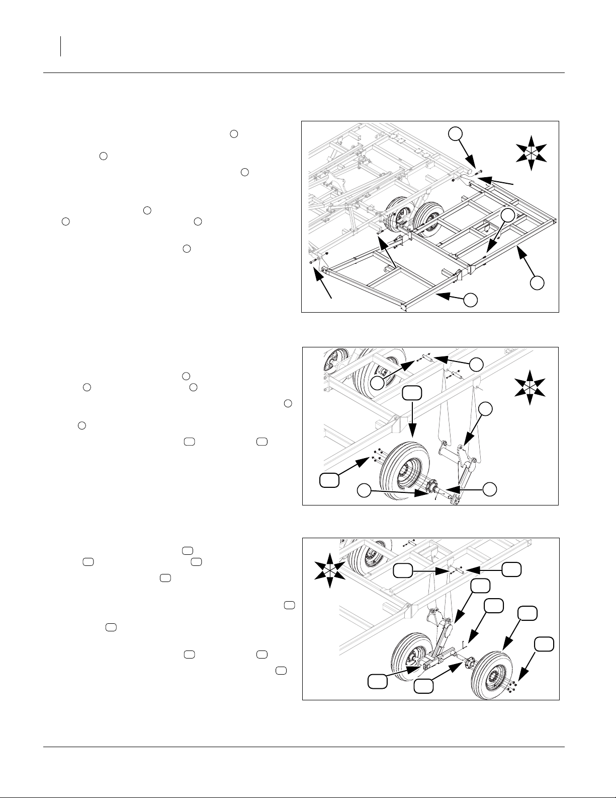
18 8321-8552DV Great Plains Manufacturing, Inc.
Install 8321-8324 Wings
Refer to Figure 10
43. Carefully align holes in wing frame LH with holes in
center frame. Secure with 1 x 7 Gr. 8 special thread
hex bolt and 1 nylon lock nut.
Note: Be sure and install the 1 x 6 hex bolts as shown
44. Attach wing brace to the front of the wing frame LH
with 3/4 x 2 Gr. 5 hex bolts , 3/4 lock washers
1 4
and 3/4 hex nuts.
45. Install 1 x 6 Gr. 5 hex bolts and 1 nylon lock nuts
through hinge in center wing brace.
2
with arrows with head against plate on side of
hinge.
3
2
1
2
2
R
F
4
U
B
L
D
1
3
Refer to Figure 11
Note: If you have a model 8324, go to Refer to Figure 12.
46. Align holes in wheel arm L , secure with 1 1/4 x 6
pins , 3/8 x 2 1/4 hex bolts and 3/8 top lock nuts.
6 7
47. Model 8321, align hole in 6-bolt spindle assembly
with wheel arm tube, secure with 5/16 x 2 13/16 clevis
pin and 1/8 x 1 cotter pin, bend over to secure.
9
48. Attach tire/wheel assembly with lug nuts .
49. Repeat same procedure for right wing.
Refer to Figure 12
50. Align holes in wheel arm L , secure with 1 1/4 x 6
pins , 3/8 x 2 1/4 hex bolts and 3/8 top lock nuts.
13 14
51. Install walking beams , See “Walking Beam
Assembly” on page 27.
52. Model 8324, align hole in 6-bolt spindle assembly
with tube of walking beam, secure with 5/16 x 2 13/16
clevis pin and 1/8 x 1 cotter pin, bend over to
secure.
53. Attach tire/wheel assembly with lug nuts .
54. Install hub/wheel on other side of walking beam .
55. Repeat same procedure for right wing.
56. Tighten all bolts to specs, See “Torque Values
Chart” on page 43.
16
5
8
10 11
12
19
15
17 18
19
R
F
11
U
D
B
L
R
F
13
42330
U
B
L
D
42330
Figure 10
8321-8324 Wing
6
7
10
5
9
Figure 11
8321 Hub/Wheel
8
14
12
16
17
18
19
15
Figure 12
8324 Hub/Wheel
42330
550-353Q-ENG 02/12/2014
Page 23
Great Plains Manufacturing, Inc. Assembly 19
Install 8321-8324 Wing Fold
Refer to Figure 13
57. Attach 1 1/4 x 9 1/2 eye bolt , secure with 1 1/4 jam
nuts (one on each side of plate).
2
58. Mount 3.5 x 8 x 1.25 cylinder to eye bolt and
wheel arm L with 1 x 3 11/16 pins , 1.5 x 1.0 x.075
machine washers and 3/16 x 2 cotter pins.
59. Mount rocker bracket to wing plate with 3/4 x 3 Gr.
5 hex bolts , 3/4 lock washers and 3/4 hex nuts.
60. Attach one end of rocker to rocker bracket using
1 x 3 3/8 pin , 1.5 x 1.0 x.075 machine washer and
3/16 x 2 cotter pin.
61. Bolt the connecting link , with 1 x 3 Gr. 5 bolts , 1
lock washers and 1 nuts.
62. Attach base end of 3.5 x 24 x 1.25 cylinders to
center fold bracket with 1 x 3 11/16 pin , 1.5 x 1.0
x.075 machine washer and 3/16 x 2 cotter pin.
Note: Do not attach rod end of fold cylinders until fold sys-
tem has been purged, See “Purging Hydraulic
System” on page 36.
63. Repeat same procedure for right wing.
64. Tighten all bolts to specs, See “Torque Values
Chart” on page 43.
6
8
5
1
3 1
4
7 5
910
11
4
R
F
11
7
4
8
6
U
B
L
D
Figure 13
8321-8324 Wing Fold
Model8321Does Not
Use Connecting Link.
9
10
5
4
3
1
2
41665
02/12/2014 550-353Q-ENG
Page 24

20 8321-8552DV Great Plains Manufacturing, Inc.
Install 8326-8333 Wings
Refer to Figure 14
65. Carefully align holes in wing frame LH with holes
1
in center frame. Secure with 1 x 7 Gr. 8 special
thread hex bolt and 1 nylon lock nut.
Note: Be sure and install the1x6hexbolts as shown
2
2
with arrows with head against plate on side of
hinge.
66. Align holes in wheel arm L , secure with 1 1/4 x 6
pin , 3/8 x 2 1/4 hex bolts and 3/8 top lock nuts.
4 5
67. install walking beams , See “Walking Beam
3
6
Assembly” on page 27.
68. Align hole in 6-bolt spindle assembly , secure with
5/16 x 2 13/16 clevis pin and 1/8 x 1 cotter pin,
8
7
bend over to secure.
69. Attach tire/wheel assembly with lug nuts .
70. Attach wing brace to the front of the wing frame
LH with 3/4 x 2 Gr. 5 hex bolts , 3/4 lock wash-
112
11
910
ers and 3/4 hex nuts.
71. Install 1 x 6 Gr. 5 hex bolt and 1 nylon lock nut
2
through hinge in center wing brace.
72. Attach 1 1/4 x 9 1/2 eye bolt , secure with 1 1/4
jam nut (one on each side plate).
14
13
73. Mount 3.25 x 8 x 1.25 cylinder (models 8326-8328)
or 3.75 x 8 x 1.38 (models 8333) to eye bolt
and wheel arm L with 1 x 3 11/16 pins , 1.5 x
3
15 13
16
1.0 x.075 machine washers and 3/16 x 2 cotter pins.
74. Mount wing fold bracket to wing with 3/4x5Gr.5
hex bolts , 3/4 lock washers and 3/4 hex nuts, 5/8
18
x 3 1/32 x 5 1/2 u-bolts , 5/8 lock washers and 5/8
17
19
hex nuts.
75. Attach base end of4x30x1.5cylinders to center
fold bracket with 1 x 3 11/16 pin , 1.5 x 1.0
21
20
16
x.075 machine washer and 3/16 x 2 cotter pin.
Note: Do not attach rod end of fold cylinders until fold
system has been purged, See “Purging Hydrau-
lic System” on page 36.
76. Repeat same procedure for right wing.
77. Tighten all bolts to specs, See “Torque Values
Chart” on page 43.
550-353Q-ENG 02/12/2014
Page 25
Great Plains Manufacturing, Inc. Assembly 21
U
R
B
16
21
F
L
D
20
17
18
15
5
12
4
16
1
14
2
13
3
8
9
11
19
6
10
7
Figure 14
8326-8333 Wing
02/12/2014 550-353Q-ENG
41653
Page 26

22 8321-8552DV Great Plains Manufacturing, Inc.
Install 8537-8552 Inside Wings
Refer to Figure 15
78. Carefully align holes in wing frame LH with holes
1
in center frame. Secure with 1 x 7 Gr. 8 special
thread hex bolt and 1 nylon lock nut.
Note: Be sure and install the1x6hexbolts as shown
2
2
with arrows with head against plate on side of
hinge.
79. Attach wheel arm L , to wing frame secure with 1
1/4 x 6 pin , 3/8 x 2 1/4 hex bolts and 3/8 top lock
4 5
3 1
nuts.
80. Install walking beams , See “Walking Beam
6
Assembly” on page 27.
81. Align hole in 6-bolt spindle assembly , secure with
5/16 x 2 13/16 clevis pin and 1/8 x 1 cotter pin,
8
7
bend over to secure.
82. Attach tire/wheel assembly with lug nuts .
910
83. Attach wing brace to the front of the wing frame
LH with 3/4 x 2 Gr. 5 hex bolts , 3/4 lock wash-
112
11
ers and 3/4 hex nuts.
84. Attach wing lock mount with 1/2 x 3 1/32 x 5 ubolts , 1/2 lock washers and 1/2 nuts.
14
13
Note: See layout section for proper placement of lock
mount .
85. Mount automatic wing latch , using 3/4 x 4 1/2 hex
bolt and 3/4 lock nut.
86. Attach bolt-on stub , to wing frame plate, using 5/8
x 1 1/2 hex bolts , 5/8 lock washers and 5/8 nuts.
13
15
16
17
18
87. Repeat same procedure for right wing.
88. Tighten all bolts to specs, See “Torque Values
Chart” on page 43.
550-353Q-ENG 02/12/2014
Page 27
Great Plains Manufacturing, Inc. Assembly 23
U
R
B
F
L
D
2
Model8548&8552 Only.
13
15
12
13
5
16
1
14
4
2
17
18
3
11
8
9
10
9
7
6
Figure 15
8537-8552 Wing
02/12/2014 550-353Q-ENG
41655
Page 28

24 8321-8552DV Great Plains Manufacturing, Inc.
Install 8537-8552 Wing Fold
Refer to Figure 16
89. Attach 1 1/4 x 9 1/2 eye bolt , secure with 1 1/4 jam
nuts (one on each side of plate).
2
90. Mount cylinder to eye bolt and wheel arm L with
1 x 3 11/16 pins , 1.5 x 1.0 x.075 machine washers
3 1
4
1
and 3/16 x 2 cotter pins.
Note: See hydraulic section of “Part’s Manual” for proper
cylinders.
91. Mount front fold bracket to wing plate with 3/4 x 3
Gr. 5 hex bolts , 3/4 x 5 1/2 hex bolt ,3/4 lock
6 7
5
washers and 3/4 hex nuts, 5/8 x 3 1/32 x 5 1/2 ubolts , 5/8 lock washers and 5/8 nuts.
8
92. Mount rear fold bracket to wing plate with 3/4 x 3
Gr. 5 hex bolts , 3/4 lock washers and 3/4 hex nuts,
6
5/8 x 3 1/32 x 5 1/2 u-bolts , 5/8 x 2 hex bolts , 5/
9
810
8 lock washers and 5/8 nuts.
93. Attach wing rest , on top of front fold bracket ,
wing rest plate , bottom of fold bracket, with 1/2 x 4
1/2 hex bolts , 1/2 lock washers and nuts.
11 5
12
13
Note: See layout section for proper placement of wing
rest pad .
94. Bolt the 180-degree fold bracket , with 5/8 x 2 hex
bolts , 5/8 x 3 1/32 x 5 1/2 u-bolts , 5/8 lock
11
14
10 8
washers and 5/8 nuts.
95. Attach base end of4x30x1.5cylinders to center
fold bracket with 1 x 3 11/16 pin , 1.5 x 1.0 x.075
4
15
machine washer and 3/16 x 2 cotter pin.
96. Do not attach rod end of fold cylinders until fold system has been purged, See “Purging Hydraulic Sys-
tem” on page 36.
97. Repeat same procedure for right wing.
98. Tighten all bolts to specs, See “Torque Values
Chart” on page 43.
550-353Q-ENG 02/12/2014
Page 29
Great Plains Manufacturing, Inc. Assembly 25
U
R
B
4
16
F
L
D
15
15
4
6
9
10
13
14
7
6
11
12
3
8
5
4
2
1
8
8
Figure 16
8537-8552 Wing Fold
02/12/2014 550-353Q-ENG
14
Models8537-8552Coulter Only.
10
41654
Page 30
26 8321-8552DV Great Plains Manufacturing, Inc.
Install 8537-8552 Outside Wings
Refer to Figure 17
99. Attach outside wing hinges , to wing frame and
wing brace , with 1 x 5 1/2 Gr. 5 hex bolt , 1 nylon
lock, 5/8 3 1/32 x 5 1/2 u-bolts , 5/8 lock washers
and 5/8 nuts.
100.Attach wing brace to the front of the wing frame LH
with 3/4 x 2 Gr. 5 hex bolts , 3/4 lock washers, 3/4
2 6
hex nuts and 1 x 6 Gr. 8 hex bolt and 1 nylon lock
nut.
101.Carefully align holes in wing hinges with holes in
inside wing fold brackets. Secure rear two hinges with
1 1/4 x 8 Gr. 8 hex bolt and 1 1/4 nylon lock nut,
front hinge with 1 x 6 Gr. 8 hex bolt and 1 nylon lock
nut.
102.Repeat same procedure for right wing.
Refer to Figure 18
Note: For Models 8548-8552, See “8548-8552 Outside
Wing Transport” on page 26
103.Attach holes in wheel arm L , to wing frame ,
secure with 1 1/4 x 6 pin , 3/8 x 2 1/4 hex bolts
and 3/8 top lock nuts.
104. Align hole in 6-bolt spindle assembly , to wheel
arm , secure with 5/16 x 2 1/16 pin and 1/8 x 1
10 14
cotter pin.
105.Attach pre-assembled tire/wheel assembly with
lug nuts .
106.Repeat same procedure for right wing.
3 5
3
16
1 2
4
7
1
8
9
10 2
11 12
13
15
R
F
5
1
8
9
7
4
1
3
Models8537-8552
Coulter Only.
4
Figure 17
8537-8552 Outside Wing
U
B
12
L
D
10
13
Figure 18
8537-8544 Outside Wing Transport
Models8537-8552
Coulter Only.
6
U
R
F
D
11
2
14
15
16
2
B
L
41666
42331
Refer to Figure 19
107.Attach holes in wheel arm L , to wing frame ,
secure with 1 1/4 x 6 pin , 3/8 x 2 1/4 hex bolts
and 3/8 top lock nuts.
108.Install walking beams , See “Walking Beam
Assembly” on page 27.
109. Align hole in 6-bolt spindle assembly , to walking
beam , secure with 5/16 x 2 13/16 clevis pin and
19 20
1/8 x 1 cotter pin, bend over to secure.
110.Attach pre-assembled tire/wheel assembly with lug
nuts .
16
111.Repeat same procedure for right wing.
112.Tighten all bolts to specs, See “Torque Values Chart”
on page 43.
550-353Q-ENG 02/12/2014
17 2
11 12
19
18
15
R
F
12
17
U
D
19
B
L
15
8548-8552 Outside Wing Transport
18
Figure 19
20
11
2
15
16
42332
Page 31

Great Plains Manufacturing, Inc. Assembly 27
Install 8537-8552 Outside Wing Fold
Refer to Figure 20
113.IAttach 1 1/4 x 9 1/2 eye bolt , secure with 1 1/4 jam
nut (one on each side plate).
2
114.Mount 3.5 x 8 x 1.25 cylinder (models 8537-8544) or
4 x 8 x 1.38 (models 8548-8552) to eye bolt and
wheel arm L with 1 x 3 11/16 pins , 1.5 x 1.0 x.075
machine washers and 3/16 x 2 cotter pins.
115.Mount bottom of rocker to wing hinge with1x33/8
clevis pin ,1.5 x 1.0 x.075 machine washer and 3/16
x 2 cotter pin, bend cotter pin over to secure.
116.Attach base end of 3.5 x 24 x 1.25 cylinders to fold
bracket with 1 x 3 11/16 pin , 1.5 x 1.0 x.075
machine washer and 3/16 x 2 cotter pin.
117.Do not attach rod end of fold cylinders until fold system has been purged, See “Purging Hydraulic Sys-
tem” on page 36.
118.When fold system is purged, attach rod end of cylinders , to top of rockers , with 1 x 7 hinge pin , 1
flat washers, 1 3/4 od rollers and 3/8 x 2 roll pins in
order shown.
119.Mount wing lock T brackets , with 1/2 x 3 1/32 x 5 ubolts , 1/2 lock washers and 1/2 nuts.
Note: See layout section for proper placement of wing lock
T brackets .
120.Repeat same procedure for right wing.
121.Tighten all bolts to specs, See “Torque Values
Chart” on page 43.
6
7 5 8
10
9
1
3 1
4
5
7
4
9
R
F
5
U
D
B
4
L
7
5
6
1
Figure 20
8537-8552 Outside Wing Fold
10
7
8
3
4
9
2
41656
Walking Beam Assembly
Note: The center and wing walking beams install the same way as shown below.
Install Bearings and Seals
Refer to Figure 21
122.Pack bearings with grease and put one on each
side of torque tube ,
123.Carefully drive grease seals (metal part of seal to
outside) into torque tube until it flush with the outside of torque tube.
2
1
3
1
1
2
3
3
2
Figure 21
Bearing & Seal
02/12/2014 550-353Q-ENG
41673
Page 32

28 8321-8552DV Great Plains Manufacturing, Inc.
Install Spindle Sleeves
Refer to Figure 22
124.Slide one spindle sleeve through the back side of
torque tube seal until it goes against bearing .
The rubber part of seal will hold it in place until the
walking beam is installed.
125.Slide the other spindle sleeve as far on to the pivot
spindle as it will go.
Note: Be sure spindle sleeve stay in position when in-
5
stalling walking beam , if not installed properly it
will not pivot correctly or will cause excessive wear.
3 2
4
4
1
4
4
6
5
4
Install Walking Beam
Refer to Figure 23
Note: Be sure spindle sleeves stay in correct positions.
126.Now align holes in walking beam with holes in
grease seals .
127.Secure with center pivot spindle , two, machine
washers , and slotted nut .
Note: Tighten slotted nut snug until all the end play is
out of bearings. If necessary to align slot with hole in
spindle, then back off nut a 1/2 slot (maximum) and
install cotter pin, bend over to secure.
Refer to Figure 24
Note: Orientate the 8544-8552 walking beam as shown.
Be sure spindle sleeves stay in correct positions.
128.Now align holes in walking beam with holes in
grease seals .
129.Secure with center pivot spindle , two, machine
washers , and slotted nut .
Note: Tighten slotted nut snug until all the end play is
out of bearings. If necessary to align slot with hole in
spindle, then back off nut a 1/2 slot (maximum) and
install cotter pin, bend over to secure.
3
7 8
3
7 8
4
6
5
8
4
6
5
8
Spindle Sleeve Assembly
Be Sure Spindle
Sleeve is installed.
8
7
6
8321-8537 Walking Beam
Be Sure Spindle
Sleeve is installed.
8
7
6
Figure 22
Figure 23
41674
1
Be Sure Spindle
Sleeve is installed.
5
41675
1
Mount Spindle Tubes
Offset Towards Top.
Be Sure Spindle
Sleeve is installed.
5
Figure 24
8544-8552 Walking Beam
550-353Q-ENG 02/12/2014
42333
Page 33

Great Plains Manufacturing, Inc. Assembly 29
Install K-Flex
Note: See layout section for proper shank placement. If
machine is equipped with magnum shanks,
Refer to Figure 25
130.Slide k-flex shank mount through slot in k-flex
clamp . Slide these two parts over frame tube in
proper location.
131.Align top hole in k-flex clip with top hole in k-flex
clamp , secure with 1/2 x 1 1/2 Gr. 5 hex bolt , 1/
2 lock washer and 1/2 nut. Install 1/2 x 5 Gr. 5 hex
bolts , 1/2 lock washers and 1/2 nuts.
132.Slide shank through slotted hole in k-flex shank
mount , secure with 5/8 x 2 Gr. 5 hex bolt and 5/
8 top lock nut. Attach sweep with 7/16 x 1 3/4 Gr. 5
plow bolts , one, 7/16 flat washer (top slotted
hole) and 7/16 nylock nuts.
133.Tighten all bolts to specs, See “Torque Values
Chart” on page 43.
2
2 4
5
6
1 7
910
1
3
8
4
1
2
9
8
Figure 25
K-Flex Assembly
7
5
3
10
6
41667
Install Magnum Shank
Note: See layout section for proper shank placement.
Refer to Figure 26
134.Loosen 1/2 x 1 1/2 hex bolt clear up to get 5/8 x 2
Gr. 5 hex bolt installed.
135.Position pre-assembled shank mount assembly
over front of frame tube in proper location. Secure
with 5/8 x 4 1/32 x 4 3/4 u-bolt and 5/8 top lock
nut.
136.Be sure the 3/4 nylock jam nut is loose enough for
shank cradle to pivot.
137.Slide shank into shank cradle until holes are
aligned, secure with 5/8 x 2 Gr. 5 hex bolt and 5/8
top lock nut.
138.Align sweep with holes on shank , secure with
7/16 x 1 3/4 plow bolts , one, 7/16 flat washer
(top slotted hole) and 7/16 nylock nuts.
139.Re-tighten 1/2 x 1 1/2 hex bolt until threads bottom out.
Note: IIMPORANT(!) Be sure and tighten 3/4 nylock
jam nut until threads bottom out to insure
that hole doesn’t wear excessively.
140.Tighten rest of bolts to specs, See “Torque Values
Chart” on page 43.
6
5
7 5
3
4
1
2
3
6
8 9
4
4
1
3
8
7
Figure 26
Magnum Shank Assembly
2
6
5
9
41668
02/12/2014 550-353Q-ENG
Page 34

30 8321-8552DV Great Plains Manufacturing, Inc.
Gang Hangers
Install Gang Hangers
Refer to Figure 27
Note: See layout section for proper gang hanger placement
of wing .
141.Install gang hanger to proper frame tube with 5/8 x 3
1/32 x 5 1/2 u-bolts , 5/8 lock washers and 5/8 nuts.
142.Slide cupped washer and spring over gang spring
bolt .Slide gang spring bolt through gang hanger
tube, secure with 1 flat washer , 1 hex nut and 1
jam nut .
143.Install gang lift cylinders , as shown, with 1 x 3 11/16
pins , 1.5 x 1.0 x.075 machine washer and 3/16 x 2
cotter pin.
144.Tighten rest of bolts to specs, See “Torque Values
Chart” on page 43.
1
1
2
4 5
3 3 1
6 7
8
9
10
10
9
2
8
7
5
4
6
1
3
Gang Hanger Spring Adjustment
Refer to Figure 28
145.Tighten 1 hex nut to preload of 8 3/4 (22.23cm)
146.Tighten down 1 jam nut , See “Refer to Figure 27”
on page 30.
147.Tighten rest of bolts to specs and bend cotter pins.
7
8
Install 8321-8537 Gauge Wheel
Refer to Figure 29
Note: Standard on model 8537 and optional on models
8321-8333, 8544-8552.
148.Install gauge wheel bracket , using 5/8 x 4 1/32 x 4
1/4 u-bolts or 5/8 x 1 1/2 hex bolt , secure with 5/8
lock washers and 5/8 nuts.
149.Attach optional angle stub extension between
gauge wheel bracket and outside wing frame with
same bolts and u-bolts.
150.Slide gauge wheel arm assembly into gauge wheel
bracket , secure with 3/4 x 4 3/8 hitch pin and
keeper. Attach the 1/2 x 1 hex bolts into gauge
wheel bracket .
151.Attach wheel/tire assembly , gauge wheel arm
assembly , secure with 1/2 x 1 wheel bolts .
152.Tighten rest of bolts to specs, See “Torque Values
Chart” on page 43.
2 3
1
1 5
1
4
1
9
4
6
7
8
Figure 27
Gang Hanger Assembly
Figure 28
Gang Hanger Spring Adjustment
41664
41575
2
1
5
6
9
3
7
4
8
Figure 29
Gauge Wheel Assembly
41662
550-353Q-ENG 02/12/2014
Page 35

Great Plains Manufacturing, Inc. Assembly 31
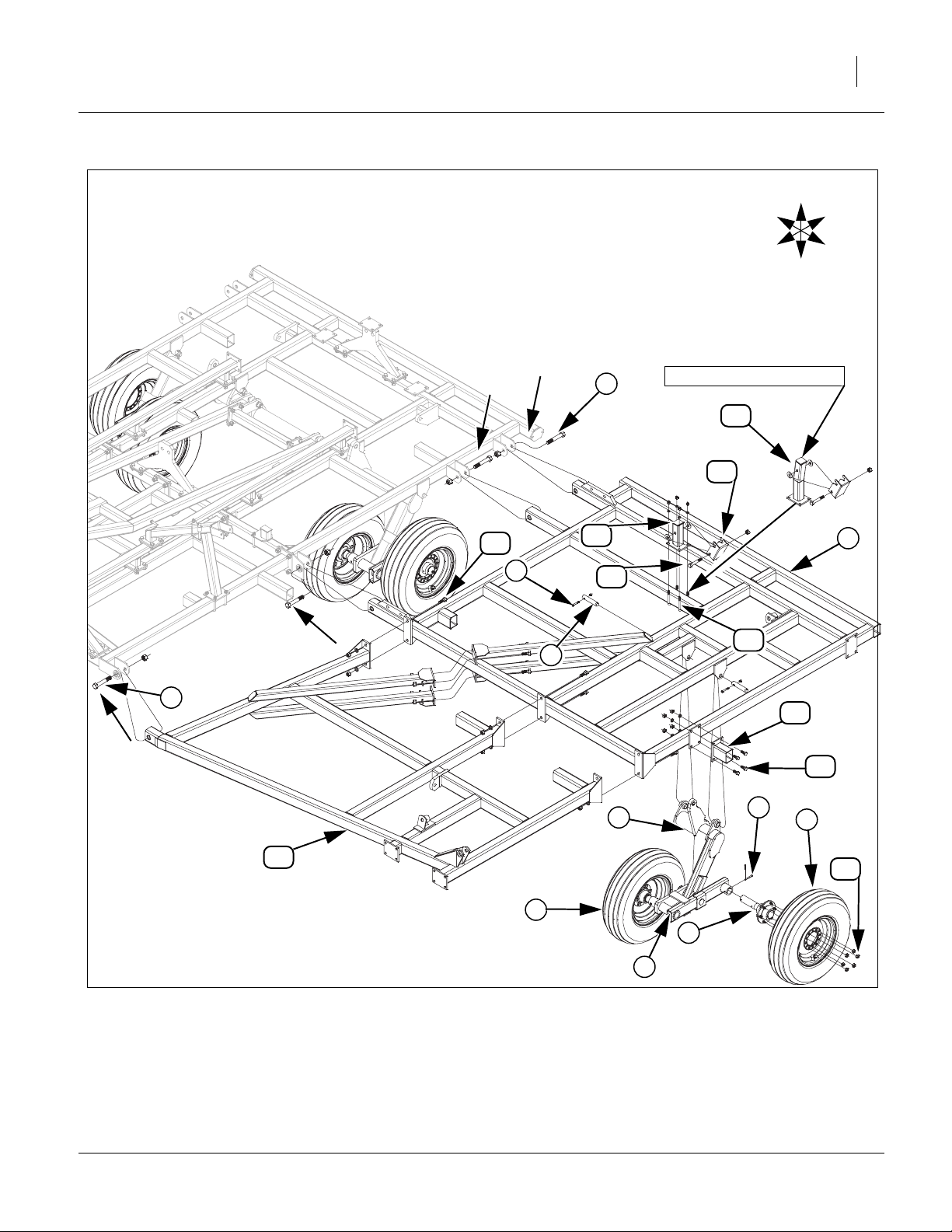
Install 8544-8552 Hydraulic Gauge Wheel
Refer to Figure 30
153.Install gauge wheel arm mounts , to plates on front
of wing brace, using 5/8 x 1 1/2 hex bolt , secure with
5/8 lock washers and 5/8 nuts.
154.Align holes in gauge wheel arm LH , with top holes
of gauge wheel arm mounts , secure with 1 x 6 hex
bolts and 1 nylon lock nuts.
4
155.Align holes in gauge wheel arm w/lever LH with top
holes of gauge wheel arm mounts , secure with1x6
hex bolts and 1 nylon lock nuts.
156.Attach 1 x 8 1/2 eye bolt , secure with 1 jam nut
(one on each side plate).
157.Mount 3.25 x 8 x 1.25 (model 8544) or 3.75 x 8 x 1.38
(models 8548-8552) cylinder to gauge wheel arm w/
lever LH , with 1 x 3 11/16 pins , 1.5 x 1.0 x.075
machine washers and 3/16 x 2 cotter pins.
158.Align holes in pivot bracket to holes in gauge wheel
arm LH and gauge wheel arm w/lever LH , secure
with 3/4 x 4 1/2 hex bolts , 3/4 lock washers and 3/4
nuts.
159.Slide gauge wheel arm spindle LH assembly up
through pivot bracket , slide friction cap , spring
, spring cover , secure with 3/4 hex nut and 3/4
14 15
jam nut.
160.Attach wheel/tire assembly to gauge wheel arm
spindle LH assembly , secure with 1/2 x 1 1/4 wheel
bolts gauge wheel arm spindle LH assembly .
161.Tighten rest of bolts to specs, See “Torque Values
Chart” on page 43.
4
6 7
5 9
3 5
11
10 13
12
1
2
3
1
5
1
8
10
12
16
13
13
10
8
15
9
14
11
12
Figure 30
Hydraulic Gauge Wheel Assembly
5
16
3
17
6
7
1
4
2
41663
Hydraulic Gauge Wheel Spring Adjustment
Refer to Figure 31
162.Adjust spring cover with 3/4 hex nut until there is a
1/4” gap between friction cap and spring cover .
163.Tighten 3/4 jam nut down against 3/4 hex nut to
secure.
02/12/2014 550-353Q-ENG
15
13 15
14
13
Figure 31
Spring Adjustment
15
41676
Page 36

32 8321-8552DV Great Plains Manufacturing, Inc.
Install Hydraulic Valves
Refer to Figure 32
164.Attach depth stop valve mounting bracket with 5/8 x
3 1/32 x 5 1/2 u-bolts , 5/8 lock washers and 5/8 nuts.
165.Align holes in depth control valve to top of depth stop
valve mounting bracket using 5/16 x 2 Gr. 5 hex bolts
and 5/16 lock washers.
4
166.Slide one end of depth stop tube (with 2 holes)
through slotted hole in depth stop valve mounting
bracket . Slide other end of depth stop tube over
peg on left side of level bar, secure with 1/2 flat washer
6 7
167.Bolt depth stop screw assembly to front of depth stop
tube with 1/2 x 2 1/2 Gr. 5 hex bolts , 1/2 lock washers and 1/2 nuts.
168.Align holes of rebound bracket on front side of center frame tube (to right of level bar mount assembly.
Align holes in rebound mount plate with holes on
rebound bracket (back side of side of center frame
tube, secure with 1/2 x 4 1/2 Gr. 5 hex bolts , 1/2 lock
washers and 1/2 nuts.
169.Mount rebound valve in position shown, with 5/16 x
4 Gr. 5 hex bolts , 5/16 lock washers and 5/16 nuts.
170.Tighten rest of bolts to specs, See “Torque Values
Chart” on page 43 and bend cotter pin.
171.Install all hydraulic fittings as shown in steps below.
1 5
and 1/8 x 1 cotter pin .
5 9
2
3
1
5
8
10
11
10
13
14
1
12
13
14
11
12
8
10
4
Figure 32
Hydraulic Valves
4
5
3
1
6
7
U
R
2
F
B
L
D
41659
550-353Q-ENG 02/12/2014
Page 37

Great Plains Manufacturing, Inc. Assembly 33
Install Rebound Valve and O-Ring Fittings
Refer to Figure 33
172.Thread straight (non- adjustable stud) fittings into
ports V1, V2 and C2 of rebound valve .
Note: Tighten as shown below. Do not over tighten as this
could cause damage to valves.
a. Inspect all components for damage or contamination
during shipping.
b. Lubricate o-ring and threads on fitting.
c. Turn fitting into port until finger tight, See “Hydraulic
Connectors and Torque” on page 45 or proper torque
value.
173.Thread elbow (adjustable stud) fitting2 into port C1 of
rebound valve .
a. Follow steps a and b from the foregoing instructions,
then proceed with the following steps below.
b.Looking from fitting from end with nut/washer/o-ring
assembly, turn nut clockwise as far as possible.
c.Using wrench, turn fitting into port until the washer
touches the port spot face. Continue turning fitting until
washer touches thread nearest wrench pad.
d.Back off fitting counterclockwise not exceeding one
revolution until it is oriented in the correct position.
e.Place wrench on the wrench pad of fitting to prevent fit-
ting from turning, and See “Hydraulic Connectors
and Torque” on page 45 for proper torque value.
1
1
3
R
F
U
2
B
3
L
D
1
3
2
Figure 33
Rebound Valve Fittings
42193
Install Depth Control Valve
Refer to Figure 34
174.Thread elbow (adjustable stud) fitting into rear port of
depth stop valve . Thread straight (non- adjustable
stud) fittings into right port of depth control valve .
175.Tighten ORB fittings as shown in, See “Rebound Valve
Fittings” on page 33.
1
3 1
2
2
3
Figure 34
Depth Control Valve Fittings
R
F
U
B
L
D
1
42099
02/12/2014 550-353Q-ENG
Page 38

34 8321-8552DV Great Plains Manufacturing, Inc.
Install Hose Handles
Refer to Figure 35
Note: Hose handles are color coded. See “Hydraulic Hose
Hookup” on page 35 for proper placement on hoses.
176.Install fittings to end of hoses running to front of
hitch. Attach poppet fittings to fittings .
177.Tighten ORB fittings as shown in, See “Rebound Valve
Fittings” on page 33.
178.Align the grooves in the front of the hose handles to
the back two ribs of fittings as shown and install the
self threading screws through holes.
179.Route hoses as shown in layout section.
2 1
3 2
4
2
5
Install JIC Fittings
Refer to Figure 36
180.Install JIC female hose to male fitting.
181.When the JIC hoses are routed, follow the following procedure for hooking up and tightening.
a.Inspect for possible contamination or damage from
shipping or handling. Sealing surface should be
smooth. Annular tool marks of (100uin) concentric with
thread permissible.
b.Lubricate the threads and the entire surface of the cone
with hydraulic fluid or a light lubricant.
c.Align mating componets for hand connection and turn
flare nut until sealing surfaces make full contact.
d.Torque nut to the values shown in, See “Hydraulic
Connectors and Torque” on page 45. If a wrench pad
is provided next to nut, place a second wrench on pad
to prevent flare from rotating while being torqued.
e.When torquing nut onto a straight flared fitting, it may be
necessary to also place a wrench on the flared fitting
wrench pad to prevent it from turning during assembly.
1
R
F
R
F
U
D
U
D
B
5
L
2
3
4
Figure 35
Hose Handle Assembly
1
41672
2
B
L
1
Figure 36
JIC Fittings Assembly
41678
550-353Q-ENG 02/12/2014
Page 39
Great Plains Manufacturing, Inc. Assembly 35
u
e
.
182.Alternate Assembly Method for JIC.
a.If torqued method not possible, follow steps a-c
(step 166), then proceed to the steps below.
b.Lightly wrench tighten the nut until there is firm
resistance.
c. Place a wrench on wrench pad next to nut as
near the 6 0’clock position as possible.
d.Place second wrench on nut as near the 3
o’clock position as possible.
e.Turn nut clockwise to no less than the 4 o’clock
position and no more than the 6 o’clock position.
Required rotation generally decreases as size
increases.
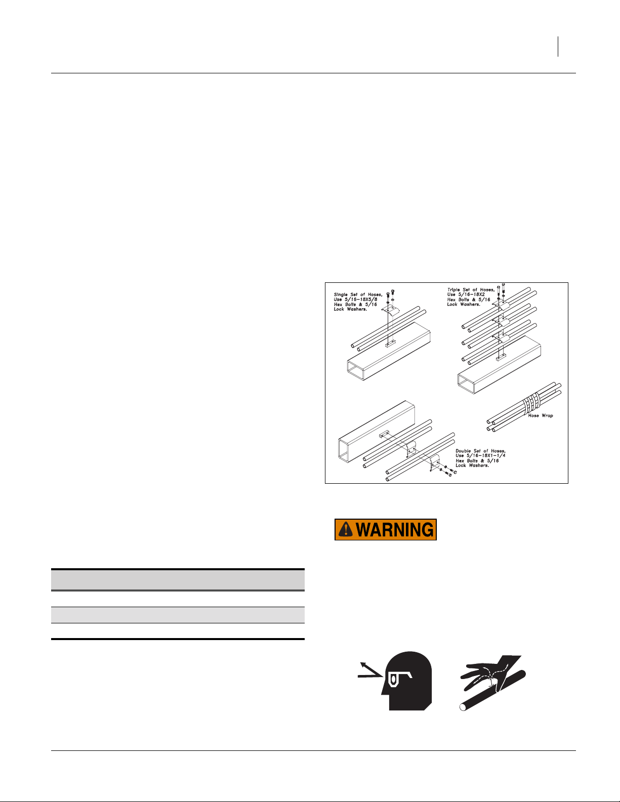
Attach Hose Clamps and Hose wraps
Refer to Figure 37
183.When all the hoses are hooked up and tightened properly, put hose clamps on hoses as shown.
184.Install hose wraps on hoses as needed.
Note: Be sure and get hoses and light wiring harness fas-
tened properly so they do not drag. Check to be sure
there is enough slack in hinge area when folding machine the first time.
Figure 37
Hose Clamp Assembly
41583
Hydraulic Hose Hookup
185.Great Plains hydraulic hoses are color coded to help you
hookup hoses to your tractor outlets. Hoses that go to
the same remote valve are marked with the same color.
Color Hydraulic Function
Black Lift (2 hoses)
Green Fold (2 hoses)
Red Gang (2 hoses)
02/12/2014 550-353Q-ENG
High Pressure Fluid Hazard:
Relieve pressure before disconnecting hydraulic lines. Use
paper or cardboard, NOT BODY PARTS, to check for leaks.
Wear protective gloves and safety glasses or goggles when
working with hydraulic systems. Escaping fluid under press
can have sufficient pressure to penetrate the skin causing s
ous injury. If an accident occurs, seek immediate medical
assistance from a physician familiar with this type of injury
Only trained personnel should work on system hydraulics.
Page 40

36 8321-8552DV Great Plains Manufacturing, Inc.
Hose Handles
Refer to Figure 38
186.To distinguish hoses on the same hydraulic circuit,
refer to hose handles. The hose under an extendedcylinder symbol feeds a cylinder base end. The hose
under a retracted-cylinder symbol feeds a cylinder rod
end.
187.Once all hoses are tightened, hook hoses to tractor
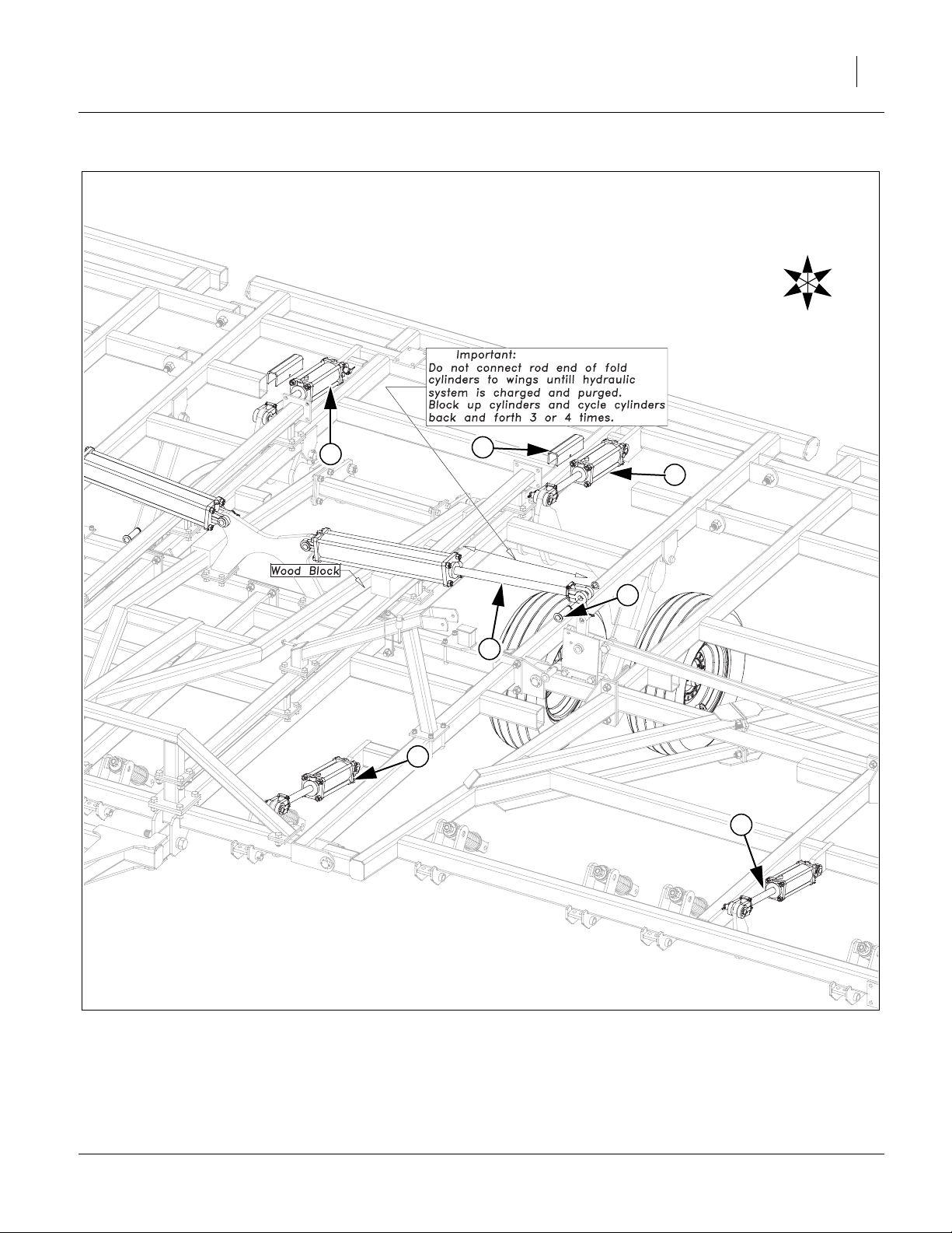
Purging Hydraulic System
Refer to Figure 39
188.Charge the lift system first. Extend the lift cylinders
(black handles) until the center section is fully
1
raise. Remove the cylinder transport locks . The
wings will not start to rise until the center cylinders
are fully extended and the master cylinders begin to
bypass oil through the rephasing ports, to the wing
cylinders. Watch for leaks and retighten fittings if
necessary. Continue to pump oil to the lift system
until the wing cylinders are also fully extended. At
this point, reverse the flow and lower the unit to the
ground, retracting all cylinders. Raise and lower the
unit several times to purge air from the system.
189.You may now charge the fold system. Before charging the fold cylinders , make sure the rod end of the
3
2
Figure 38
41552
Hose Handles
cylinders are un pinned and block is under cylinder
as shown, so that when the rod is extended, it will
clear the wing fold brackets. Extend the fold cylinders
(green ends) completely and then close them.
3
Extend and retract the cylinders several times to
purge air from the system. Now the cylinders may be
extended far enough to be connected to the wing fold
brackets. Remove wood block and install1x311/16
pin , 1.5 x 1.0 x.075 machine washer and 3/16 x 2
4
cotter pin.
190. The gang lift system (red handles), will need
5
purged like the lift system. Raise and lower the gang
system several times to purge air from system.
550-353Q-ENG 02/12/2014
Page 41
Great Plains Manufacturing, Inc. Assembly 37
U
R
B
F
L
D
1
2
1
4
3
5
5
Figure 39
Hydraulic Purging
02/12/2014 550-353Q-ENG
41660
Page 42

38 8321-8552DV Great Plains Manufacturing, Inc.
Install Gang Assembly
Note: See layout section for proper gang assembly
placement.
Refer to Figure 40
Note: The disc or coulter gang assemblies will be shipped
1
banded together. Carefully un-band the assemblies.
The L bundle number will be written on a blade of
each gang assembly.
191.Carefully slide gang assembly under gang hanger
1
and slowly lower machine down until front holes line up,
secure with 1 x 5 1/2 pin , 3/8 x 2 1/4 Gr. 8 hex bolt
2 3
and 3/8 top lock nut. Slide clevis end of gang spring bolt
over rear hole of gang frame, secure with 3/4 x 2 1/2
4
pin , 3/4 flat washer and 5/32 x 1 1/2 cotter pin.
5
192.Tighten rest of bolts to specs, See “Torque Values
Chart” on page 43.
1
4
3
2
5
Straight Gang Depth Indicator Installation
Note: See layout section for proper depth indicator tower
placement.
Refer to Figure 41
193.Attach depth indicator tower (models 8321D-8552D)
to angled tube or (models 8321C-8328C) to straight
front tube of center wing brace as shown, secure with
1/2 x 3 1/32 x 5 u-bolts , 1/2 lock washers and 1/2
nuts.
194.Align holes on one end of the depth indicator links
(one on each side) of the lever on the gang hanger,
secure with a 1/2 x 1 1/2 Gr. 5 hex bolt and 1/2 top
lock nut. Slide bent end of depth indicator pointer
through slot in depth indicator tower . Slide other end
of depth indicator pointer over peg on center wing
brace, secure with 1/2 flat washer and 1/8 x 1 1/2
cotter pin. Slide other end of depth indicator links
over depth indicator pointer , secure with two, 1/2 flat
washers , 1/2 x 1/2 Gr. 5 hex bolt and 1/2 top lock
6 5
nut.
195.Torque u-bolts to specs, See “Torque Values Chart”
2
on page 43. Tighten 1/2 x 1 1/2 Gr. 5 hex bolts down
snug but leave loose enough to pivot. Bend 1/8 x 1 1/2
cotter pin over.
7
196.See “Depth Guide Decal Placement” on page 39 for
placement of Depth Guide Decal .
1
2
3
5
4
1
4
6
3
4
5
8
1
Figure 40
1
Gang to Gang Hanger
1
4
41661
4
6
5
1
3
2
Figure 41
Straight Gang Depth Indicator
41669
550-353Q-ENG 02/12/2014
Page 43

Great Plains Manufacturing, Inc. Assembly 39
Angled Gang Depth Indicator Installation
Note: See layout section for proper depth indicator tower
placement.
8
Refer to Figure 42
197.Attach depth indicator tower (models 8333C-8552C)
8
to tube of center wing brace as shown, secure with 1/2
x 3 1/32 x 3 u-bolts , 1/2 lock washers and 1/2 nuts.
9
8
198.The rest of the parts install like, See “Straight Gang
Depth Indicator” on page 38.
9
Install Depth Guide Decal
Refer to Figure 43
199.Be sure the spring preload is set at dimension shown.
Move the top of the gang blades to the dimension
shown. Clean the front of the plate on the tower and
place the decal with the pointer at “O”.
200.See Operating Section in “Operator’s Manual” for
proper depth in field operation.
Figure 42
Angled Gang Depth Indicator
Figure 43
Depth Guide Decal Placement
41677
41577
02/12/2014 550-353Q-ENG
Page 44

40 8321-8552DV Great Plains Manufacturing, Inc.
Lights and SMV Assembly
Refer to Figure 44
201.Fasten light bracket LH to stub plate of center
frame with 1/2 x 1 1/2 Gr. 5 hex bolts , 1/2 lock
1
3
washers and 1/2 huts. Repeat same procedure for
light bracket RH .
202.Attach light mounting brackets to rear side tube as
2
4
shown, of center frame, with 1/2 x 4 1/32 x 4 u-bolts
, 1/2 lock washers and 1/2 huts.
5
203.Attach smv post (models 8321-8333) to back side
of same tube as light mounting brackets , as close
6
4
to center as possible. Secure with 1/2 x 4 1/32 x 4 ubolts , 1/2 lock washers and 1/2 huts. Attach smv
5
sign to back side of smv post , secure with 1/4 x
7 6
3/4 pan head screws , 1/4 lock washers and 1/4
8
nuts.
204.Route light harness 30’ lead from front of hitch
9
(tractor plug to front), along same route as hydraulic
hose (fasten in same clamps and hose wraps as
hoses). Plug one end of enhance light harness to
small end of light harness 30’ lead . Plug bigger
end of wishbone light harness into other end of
enhance light module . Route other ends over
10
9
11
10
towards (marked left and right) the light mounting
brackets as shown.
205.Mount red lamp lights to top of light mounting
brackets , with 1/4 x 1 Gr. 5 hex bolts and 1/4
414
12
lock nuts.
206.Mount amber lamp lights to top of light brackets
and , with 1/4 x 1 Gr. 5 hex bolts and 1/4 lock
1 214
13
nuts.
207.Tighten all bolts to specs. Be sure and get all wiring
harnesses fastened up securely with hose wraps or
clamps (if routed close to hydraulic hoses) or use
cable ties .
15
550-353Q-ENG 02/12/2014
Page 45

Great Plains Manufacturing, Inc. Assembly 41
U
R
B
13
F
L
D
12
7
8
11
2
12
6
9
15
14
5
10
13
5
4
3
1
Figure 44
Lights & SMV
02/12/2014 550-353Q-ENG
41659
Page 46

42 8321-8552DV Great Plains Manufacturing, Inc.
Rear Hitch Assembly (optional)
Refer to Figure 45
Note: The rear tow hitch will be shipped with big compo-
nents banded together and bolts will be in a box.
Carefully un-band the components.
208.Attach left and right rear hitch arms, rear hitch
truss , rear truss support to center frame using
5/8 x 1 1/2 bolts , 5/8 x 3 1/32 x 5 1/2 u-bolts ,
secure with 5/8 lock washers and 5/8 nuts.
Note: Do not tighten any bolts until every thing is in-
stalled.
209.Now install the rear hitch frame using 5/8 x 1 1/2
bolts , 5/8 x 4 1/32 x 4 1/4 u-bolts , secure with
5/8 lock washers and 5/8 nuts.
210.The bolt on sleeve assembly with rigid or flex slide
may be fastened using 5/8 x 3 1/32 x 4 1/2 u-bolt
9
10
, secure with 5/8 lock washers and 5/8 nuts.
211. Tighten all bolts to specs, See “Torque Values
Chart” on page 43.
212.If machine is equipped with optional rear hitch
accessory kit may be installed as shown in “Parts
Manual”.
213.Route hoses and light harness along hitch and
frame with hose clamps and hose wraps, provided.
Note: Be sure hoses and light harness is fastened se-
curely so they don’t drag or get pinched.
2 1
4 5
6 7
3
6 8
6
5
46
6
6
1
6
3
10
7
7
2
8
9
Figure 45
Rear Hitch
9
41423
Completing Setup
214.If the Discovator is equipped with an optional finishing attachment, refer to “Parts Manual” for parts
breakdown.
215.Once the options are installed, fold the Discovator
to check for clearance and interferences. Slowly fold
Discovator while watching that hoses and wiring
harnesses do not become pinched or kinked while
watching for interferences.
Note: Double check that all bolts are tightened to specs,
See “Torque Values Chart” on page 43.Consult
the operating instructions, “Operator’s Manual”,
for the first time field adjustments before going to
the field.
550-353Q-ENG 02/12/2014
Page 47

Great Plains Manufacturing, Inc. 43
Appendix
Torque Values Chart
Bolt
Size
in-tpi
1
⁄4-20
1
⁄4-28
5
⁄16-18
5
⁄16-24
3
⁄8-16
3
⁄8-24
7
⁄16-14
7
⁄16-20
1
⁄2-13
1
⁄2-20
9
⁄16-12
9
⁄16-18
5
⁄8-11
5
⁄8-18
3
⁄4-10
3
⁄4-16
7
⁄8-9
7
⁄8-14
1-8
1-12
1
1
⁄8-7
1
1
⁄8-12
1
⁄4-7
1
1
⁄4-12
1
3
⁄8-6
1
3
1
⁄8-12
1
1
⁄2-6
1
1
⁄2-12
Bolt Head Identification
Grade 2 Grade 5 Grade 8 Class 5.8 Class 8.8 Class 10.9
a
b
d
N-m
ft-lb
7.4 11 16
8.5 13 18
15 24 33
17 26 37
27 42 59
31 47 67
43 67 95
49 75 105
66 105 145
75 115 165
95 150 210
105 165 235
130 205 285
150 230 325
235 360 510
260 405 570
225 585 820
250 640 905
340 875 1230
370 955 1350
480 1080 1750
540 1210 1960
680 1520 2460
750 1680 2730
890 1990 3230
1010 2270 3680
1180 2640 4290
1330 2970 4820
N-m N-m
5.6 8 12
61014 5 811
11 17 25 12 19 27
13 19 27 13 21 29
20 31 44 24 39 53
22 35 49 29 45 62
32 49 70 42 67 93
36 55 78 44 70 97
49 76 105 66 77 105
55 85 120 68 105 150
70 110 155 73 115 160
79 120 170 105 165 230
97 150 210 115 180 245
110 170 240 145 230 300
170 265 375 165 260 355
190 295 420 205 325 450
165 430 605 230 480 665
185 475 670 355 560 780
250 645 910 390 610 845
275 705 995 705 1120 1550
355 795 1290 785 1240 1710
395 890 1440 1270 1950 2700
500 1120 1820 1380 2190 3220
555 1240 2010
655 1470 2380
745 1670 2710
870 1950 3160
980 2190 3560
Bolt Head Identification
Bolt
Size
ft-lb ft-lb ft-lb ft-lb ft-lb
mm x pitch
M 5 X 0.8
M 6 X 1
M 8 X 1.25
M 8 X 1
M10 X 1.5
M10 X 0.75
M12 X 1.75
M12 X 1.5
M12 X 1
M14 X 2
M14 X 1.5
M16 X 2
M16 X 1.5
M18 X 2.5
M18 X 1.5
M20 X 2.5
M20 X 1.5
M24 X 3
M24 X 2
M30 X 3.5
M30 X 2
M36 X 3.5
M36 X 2
a. in-tpi = nominal thread diameter in inches-threads per inch
b. N· m = newton-meters
c. mm x pitch = nominal thread diameter in mm x thread pitch
d. ft-lb = foot pounds
c
5.8 8.8 10.9
N-m N-m N-m
357
71115
17 26 36
18 28 39
33 52 72
39 61 85
58 91 125
60 95 130
90 105 145
92 145 200
99 155 215
145 225 315
155 240 335
195 310 405
220 350 485
280 440 610
310 650 900
480 760 1050
525 830 1150
960 1510 2100
1060 1680 2320
1730 2650 3660
1880 2960 4100
946
Torque tolerance + 0%, -15% of torquing values. Unless otherwise specified use torque values listed above.
25199m
25199
Disc or Coulter Gang Bolt Torque 1 1/2”-6 650-750 Foot-pounds (175 lbs on 4’ cheater).
02/12/2014 550-353Q-ENG
Page 48

44 8321-8552DV Great Plains Manufacturing, Inc.
Tire Inflation and Warranty
Tire Inflation Chart
Wheel Tire Size Inflation
Gauge
Wheel
Gauge
Wheel
Transport/
Wings
Transport/
Center
Transport/
Center
Transport/
Center
Transport/
Center
6.70L-15” 4-ply
7.50x10” 10-ply
9.5L-15” 8-Ply
11L x 15SL 12-Ply
11L x 15” Load F
12.5L x Load F
12.5L x 16.5” Load
G Galaxy
32psi
(221 kPa)
80 psi
(552 kPa)
44psi
(303 kPa)
52 psi
(359 kPa)
90psi
(621 kPa)
90 psi
(621 kPa)
105 psi
(724 kPa)
Tire Warranty Information
All tires are warranted by the original manufacturer of the tire.
Tire warranty information is found in the brochures included with
your Operator’s and Parts Manuals or online at the manufacturer’s web sites listed below. For assistance or information, contact your nearest Authorized Farm Tire Retailer.
Manufacturer Web site
Firestone www.firestoneag.com
Gleason www.gleasonwheel.com
Titan www.titan-intl.com
550-353Q-ENG 02/12/2014
Page 49

Great Plains Manufacturing, Inc. Appendix 45
Hydraulic Connectors and Torque
Refer to Figure 46 (a hypothetical fitting)
Leave any protective caps in place until immediately prior
to making a connection.
1
NPT - National Pipe Thread
Note tapered threads, no cone/flare, and no O-ring.
Apply liquid pipe sealant for hydraulic applications.
Do not use tape sealant, which can clog a filter and/or
plug an orifice.
2
JIC - Joint Industry Conference (SAE J514)
Note straight threads and the 37° cone on
“M” fittings (or 37° flare on “F” fittings).
Use no sealants (tape or liquid) on JIC fittings.
3
ORB - O-Ring Boss (SAE J514)
Note straight threads and elastomer O-Ring .
Prior to installation, to prevent abrasion during tightening, lubricate O-Ring with clean hydraulic fluid.
Use no sealants (tape or liquid) on ORB fittings.
ORB fittings that need orientation, such as the ell
depicted, also have a washer and jam nut
(“adjustable thread port stud”). Back jam nut away
from washer. Thread fitting into receptacle until
O-Ring contacts seat. Unscrew fitting to desired
orientation. Tighten jam nut to torque specification.
4 5
5 7
8 9
5
Dash
Size
-4
-5
-5
-5
-6
-6
-6
-8
-8
-8
1
9
8
4
2
Figure 46
Hydraulic Connector ID
Fittings Torque Values
Fitting N-m Ft-Lbs
1
⁄4-18 NPT 1.5-3.0 turns past finger
tight
1
⁄2-20 JIC 19-20 14-15
1
⁄2-20 ORB w/jam nut 12-16 9-12
1
⁄2 -20 ORB straight 19-26 14-19
5
⁄16-18 JIC 24-27 18-20
5
⁄16-18 ORB w/jam nut 16-22 12-16
5
⁄16-18 ORB straight 24-33 18-24
3
⁄4 -16 JIC 37-53 27-39
3
⁄4 -16 ORB w/jam nut 27-41 20-30
3
⁄4-16 ORB straight 37-58 27-43
7
5
3
31282
02/12/2014 550-353Q-ENG
Page 50

46 8321-8552DV Great Plains Manufacturing, Inc.
8321-8333 Lift & Gang Layout
41679
550-353Q-ENG 02/12/2014
Page 51

Great Plains Manufacturing, Inc. Appendix 47
8321-8333 Fold Layout
41680
02/12/2014 550-353Q-ENG
Page 52

48 8321-8552DV Great Plains Manufacturing, Inc.
8537 Lift & Gang Layout
41681
550-353Q-ENG 02/12/2014
Page 53

Great Plains Manufacturing, Inc. Appendix 49
8537 Lift & Gang Layout
41684
02/12/2014 550-353Q-ENG
Page 54

50 8321-8552DV Great Plains Manufacturing, Inc.
8544-8552 Lift & Gang Layout
41682
550-353Q-ENG 02/12/2014
Page 55

Great Plains Manufacturing, Inc. Appendix 51
8544-8552 Lift & Gang Layout
41685
02/12/2014 550-353Q-ENG
Page 56

52 8321-8552DV Great Plains Manufacturing, Inc.
8537-8552 Fold Layout
41683
550-353Q-ENG 02/12/2014
Page 57

Great Plains Manufacturing, Inc. Appendix 53
8537-8552 Fold Layout
41686
02/12/2014 550-353Q-ENG
Page 58

54 8321-8552DV Great Plains Manufacturing, Inc.
8321D Machine Layout, Disc
41465
550-353Q-ENG 02/12/2014
Page 59

Great Plains Manufacturing, Inc. Appendix 55
8321C Machine Layout, Coulter
41466
02/12/2014 550-353Q-ENG
Page 60

56 8321-8552DV Great Plains Manufacturing, Inc.
8324D Machine Layout, Disc
41467
550-353Q-ENG 02/12/2014
Page 61

Great Plains Manufacturing, Inc. Appendix 57
8324C Machine Layout, Coulter
41468
02/12/2014 550-353Q-ENG
Page 62

58 8321-8552DV Great Plains Manufacturing, Inc.
8326D Machine Layout, Disc
40886
550-353Q-ENG 02/12/2014
Page 63

Great Plains Manufacturing, Inc. Appendix 59
8326C Machine Layout, Coulter
40887
02/12/2014 550-353Q-ENG
Page 64
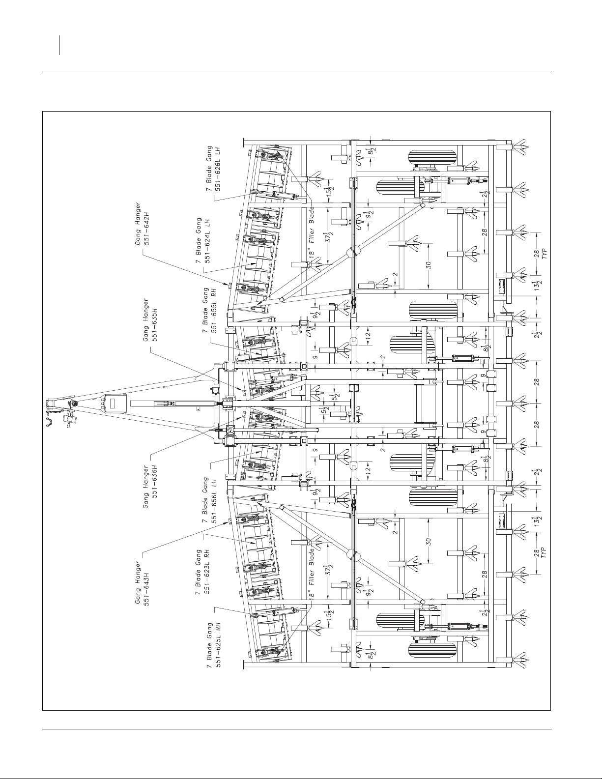
60 8321-8552DV Great Plains Manufacturing, Inc.
8328D Machine Layout, Disc
40888
550-353Q-ENG 02/12/2014
Page 65

Great Plains Manufacturing, Inc. Appendix 61
8328C Machine Layout, Coulter
40889
02/12/2014 550-353Q-ENG
Page 66

62 8321-8552DV Great Plains Manufacturing, Inc.
8333D Machine Layout, Disc
40942
550-353Q-ENG 02/12/2014
Page 67

Great Plains Manufacturing, Inc. Appendix 63
8333C Machine Layout, Coulter
40943
02/12/2014 550-353Q-ENG
Page 68

64 8321-8552DV Great Plains Manufacturing, Inc.
8537D Machine Layout, Disc
40944
550-353Q-ENG 02/12/2014
Page 69

Great Plains Manufacturing, Inc. Appendix 65
8537D Machine Layout, Disc
40945
02/12/2014 550-353Q-ENG
Page 70

66 8321-8552DV Great Plains Manufacturing, Inc.
8537C Machine Layout, Coulter
40946
550-353Q-ENG 02/12/2014
Page 71

Great Plains Manufacturing, Inc. Appendix 67
8537C Machine Layout, Coulter
40947
02/12/2014 550-353Q-ENG
Page 72

68 8321-8552DV Great Plains Manufacturing, Inc.
8544D Machine Layout, Disc
40890
550-353Q-ENG 02/12/2014
Page 73

Great Plains Manufacturing, Inc. Appendix 69
8544D Machine Layout, Disc
40891
02/12/2014 550-353Q-ENG
Page 74

70 8321-8552DV Great Plains Manufacturing, Inc.
8544C Machine Layout, Coulter
40892
550-353Q-ENG 02/12/2014
Page 75

Great Plains Manufacturing, Inc. Appendix 71
8544C Machine Layout, Coulter
40893
02/12/2014 550-353Q-ENG
Page 76

72 8321-8552DV Great Plains Manufacturing, Inc.
8548D Machine Layout, Disc
40948
550-353Q-ENG 02/12/2014
Page 77

Great Plains Manufacturing, Inc. Appendix 73
8548D Machine Layout, Disc
40949
02/12/2014 550-353Q-ENG
Page 78

74 8321-8552DV Great Plains Manufacturing, Inc.
8548C Machine Layout, Coulter
40950
550-353Q-ENG 02/12/2014
Page 79

Great Plains Manufacturing, Inc. Appendix 75
8548C Machine Layout, Coulter
40951
02/12/2014 550-353Q-ENG
Page 80

76 8321-8552DV Great Plains Manufacturing, Inc.
8552D Machine Layout, Disc
43206
550-353Q-ENG 02/12/2014
Page 81

Great Plains Manufacturing, Inc. Appendix 77
8552D Machine Layout, Disc
43211
02/12/2014 550-353Q-ENG
Page 82

78 8321-8552DV Great Plains Manufacturing, Inc.
8552C Machine Layout, Coulter
43265
550-353Q-ENG 02/12/2014
Page 83

Great Plains Manufacturing, Inc. Appendix 79
8552C Machine Layout, Coulter
43266
02/12/2014 550-353Q-ENG
Page 84

80 8321-8552DV Great Plains Manufacturing, Inc.
8321DV HD 3 Bar Spike W/Reel
42890
550-353Q-ENG 02/12/2014
Page 85

Great Plains Manufacturing, Inc. Appendix 81
8321DV S7T Spike Drag
42891
02/12/2014 550-353Q-ENG
Page 86

82 8321-8552DV Great Plains Manufacturing, Inc.
8321DV S5T HR Spike Drag
42892
550-353Q-ENG 02/12/2014
Page 87

Great Plains Manufacturing, Inc. Appendix 83
8321DV CH4B Coil Tine
42893
02/12/2014 550-353Q-ENG
Page 88

84 8321-8552DV Great Plains Manufacturing, Inc.
8324DV HD 3 Bar Spike W/Reel
42894
550-353Q-ENG 02/12/2014
Page 89

Great Plains Manufacturing, Inc. Appendix 85
8324DV S7T Spike Drag
42895
02/12/2014 550-353Q-ENG
Page 90

86 8321-8552DV Great Plains Manufacturing, Inc.
8324DV S5T HR Spike Drag
42896
550-353Q-ENG 02/12/2014
Page 91

Great Plains Manufacturing, Inc. Appendix 87
8324DV CH4B Coil Tine
42897
02/12/2014 550-353Q-ENG
Page 92

88 8321-8552DV Great Plains Manufacturing, Inc.
8326DV HD 3 Bar Spike W/Reel
42898
550-353Q-ENG 02/12/2014
Page 93

Great Plains Manufacturing, Inc. Appendix 89
8326DV S7T Spike Drag
42899
02/12/2014 550-353Q-ENG
Page 94

90 8321-8552DV Great Plains Manufacturing, Inc.
8326DV S5T HR Spike Drag
42900
550-353Q-ENG 02/12/2014
Page 95

Great Plains Manufacturing, Inc. Appendix 91
8326DV CH4B Coil Tine
42901
02/12/2014 550-353Q-ENG
Page 96

92 8321-8552DV Great Plains Manufacturing, Inc.
8328DV HD 3 Bar Spike W/Reel
42902
550-353Q-ENG 02/12/2014
Page 97

Great Plains Manufacturing, Inc. Appendix 93
8328DV S7T Spike Drag
42903
02/12/2014 550-353Q-ENG
Page 98

94 8321-8552DV Great Plains Manufacturing, Inc.
8328DV S5T HR Spike Drag
42904
550-353Q-ENG 02/12/2014
Page 99

Great Plains Manufacturing, Inc. Appendix 95
8328DV CH4B Coil Tine
42905
02/12/2014 550-353Q-ENG
Page 100

96 8321-8552DV Great Plains Manufacturing, Inc.
8333DV HD 3 Bar Spike W/Reel
42906
550-353Q-ENG 02/12/2014
 Loading...