

Table of Contents Index
Pre-Delivery Manual
8315-8324DVN
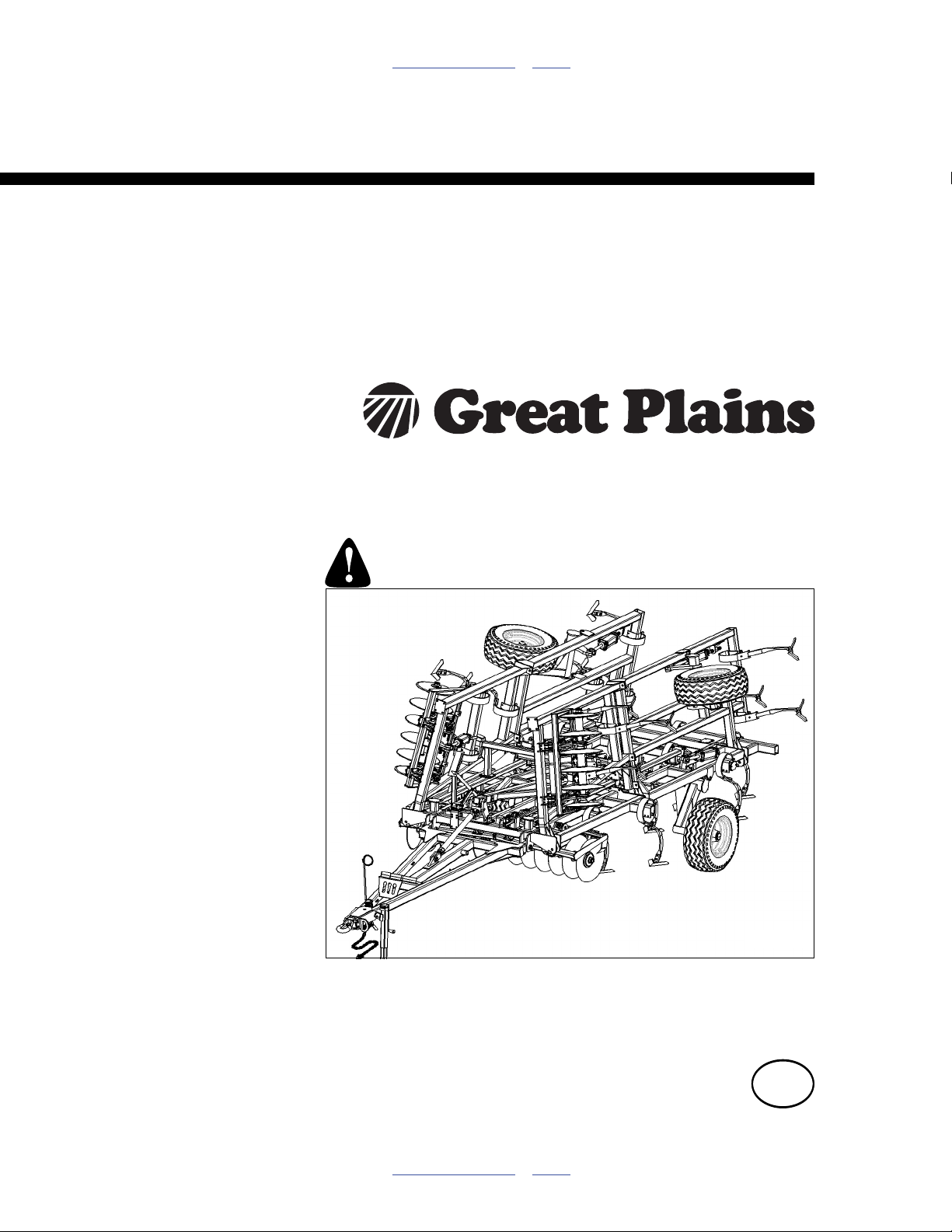
Series VIII Discovator, DVN (Disc & Coulter)
Manufacturing, Inc.
www.greatplainsmfg.com
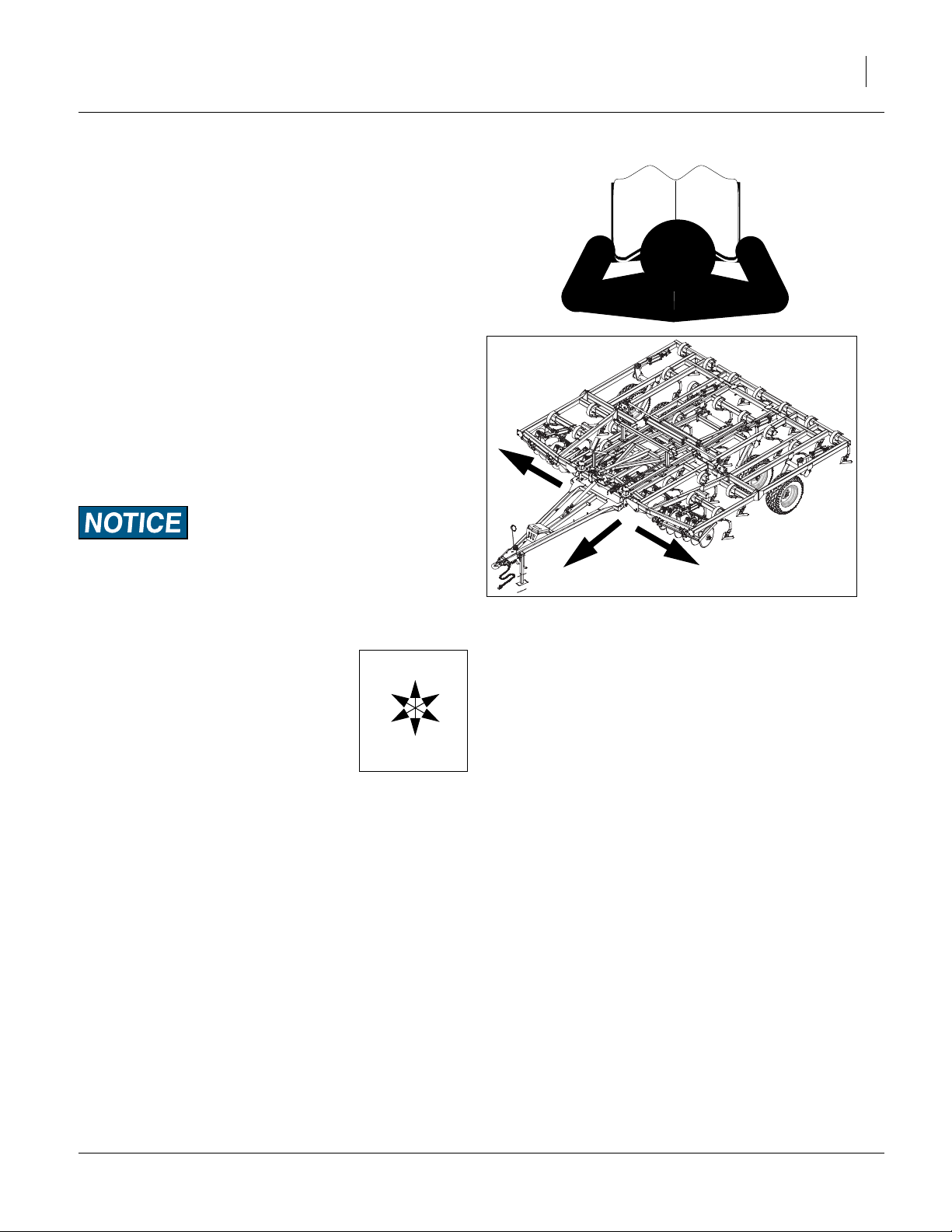
Read the operator’s manual entirely. When you see this symbol, the
subsequent instructions and warnings are serious - follow without
exception. Your life and the lives of others depend on it!
Illustrations may show optional equipment not supplied with standard unit.
41541
ORIGINAL INSTRUCTIONS
© Copyright 2013 Printed 2013-11-25 550-466Q
Table of Contents Index
EN

Table of Contents Index
Table of Contents Index

Great Plains Manufacturing, Inc. iii
Table of Contents
Important Safety Information ...................................... 1
Introduction ..................................................................4
Description of Unit ..........................................................4
Models Covered ............................................................. 4
Document Family ...........................................................4
Tools Required ...............................................................4
Pre-assembly Checklist..................................................4
Using This Manual..........................................................5
Definitions................................................................... 5
Shipping ........................................................................6
Unloading......................................................................7
Unload Smaller Items First .........................................7
Unload Discovator ......................................................7
Unpacking Boxes .......................................................7
Assembly and Setup Assistance ................................7
Assembly ......................................................................8
Install Center Hub/Wheel............................................8
Install K-Flex Shanks.................................................. 8
Install Magnum Shanks ..............................................9
Attach Disc or Coulter Gangs.....................................9
Install Lights and SMV.............................................. 10
Install Rear Hitch (optional) ......................................11
Completing Setup.........................................................12
Appendix - Reference Information............................13
Torque Values Chart .................................................... 13
Tire Inflation Chart........................................................14
Hydraulic Connectors and Torque................................14
Lift and Gang Hydraulic Layout ....................................15
Fold Hydraulic Layout ................................................. 16
Retract Layout ............................................................. 17
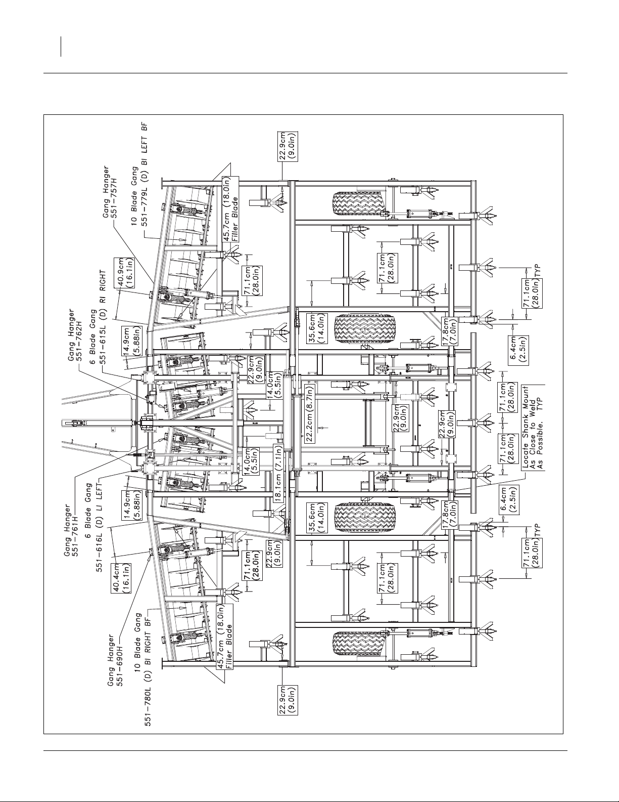
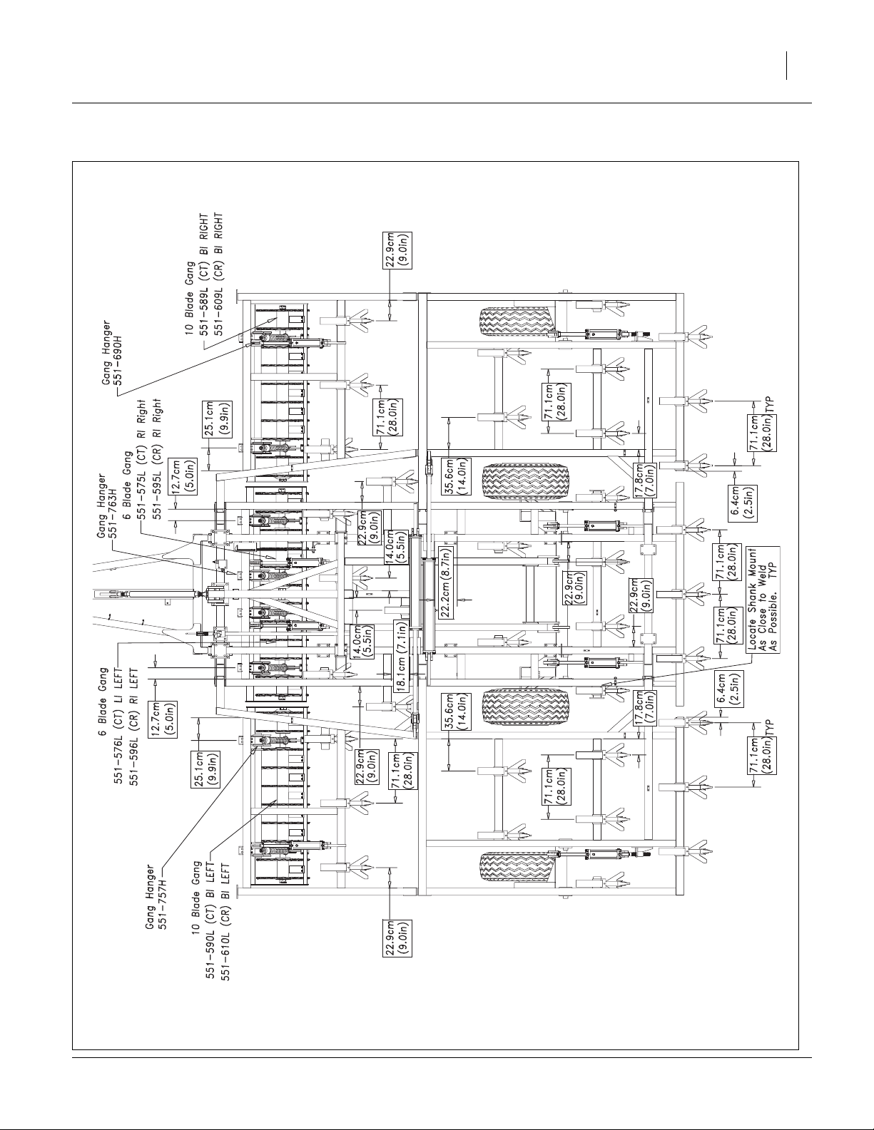
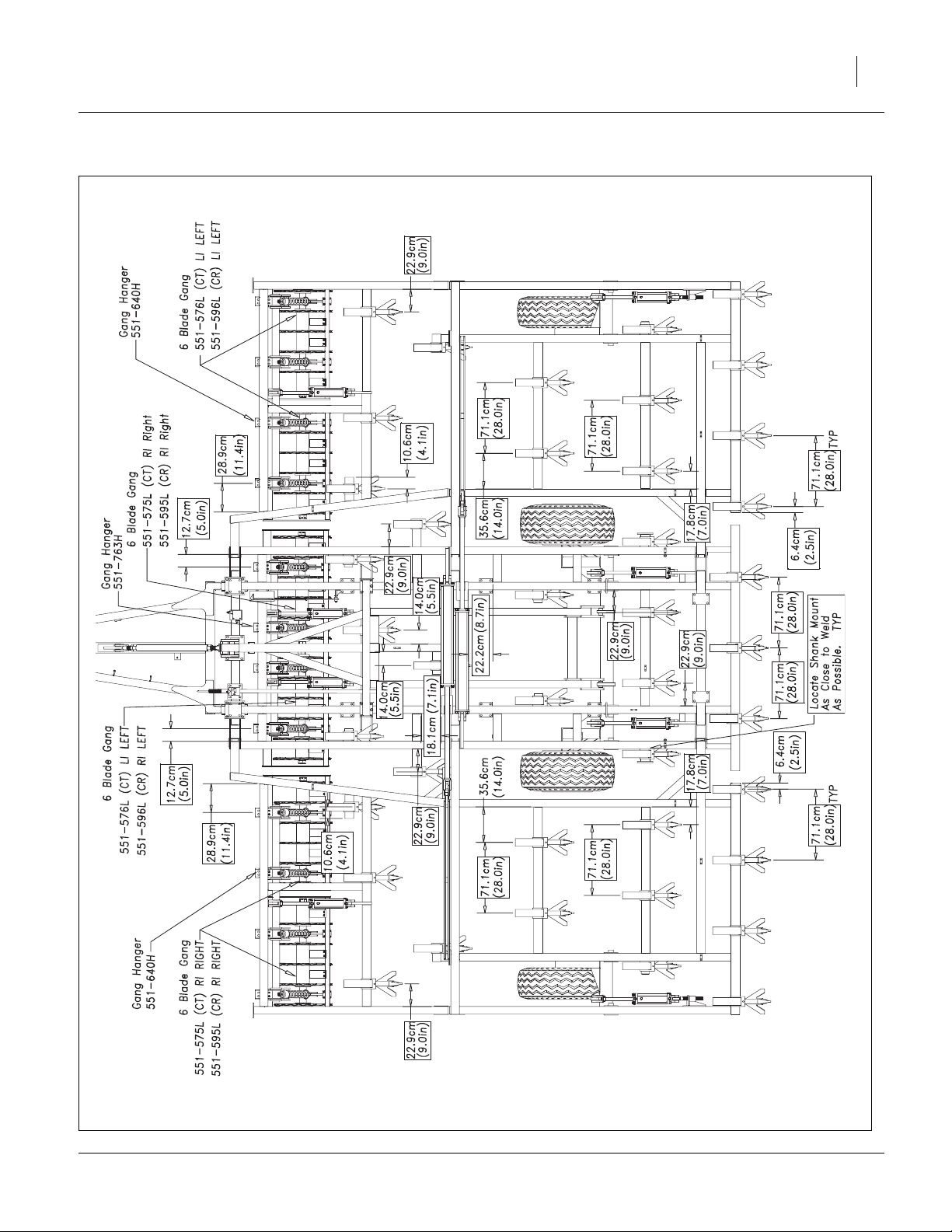
8315D Machine Layout, Disc ....................................... 18
8315C Machine Layout, Coulter .................................. 19
8318D Machine Layout, Disc ....................................... 20
8318C Machine Layout, Coulter .................................. 21
8321D Machine Layout, Disc ....................................... 22
8321C Machine Layout, Coulter .................................. 23
8324D Machine Layout, Disc ....................................... 24
8324C Machine Layout, Coulter .................................. 25
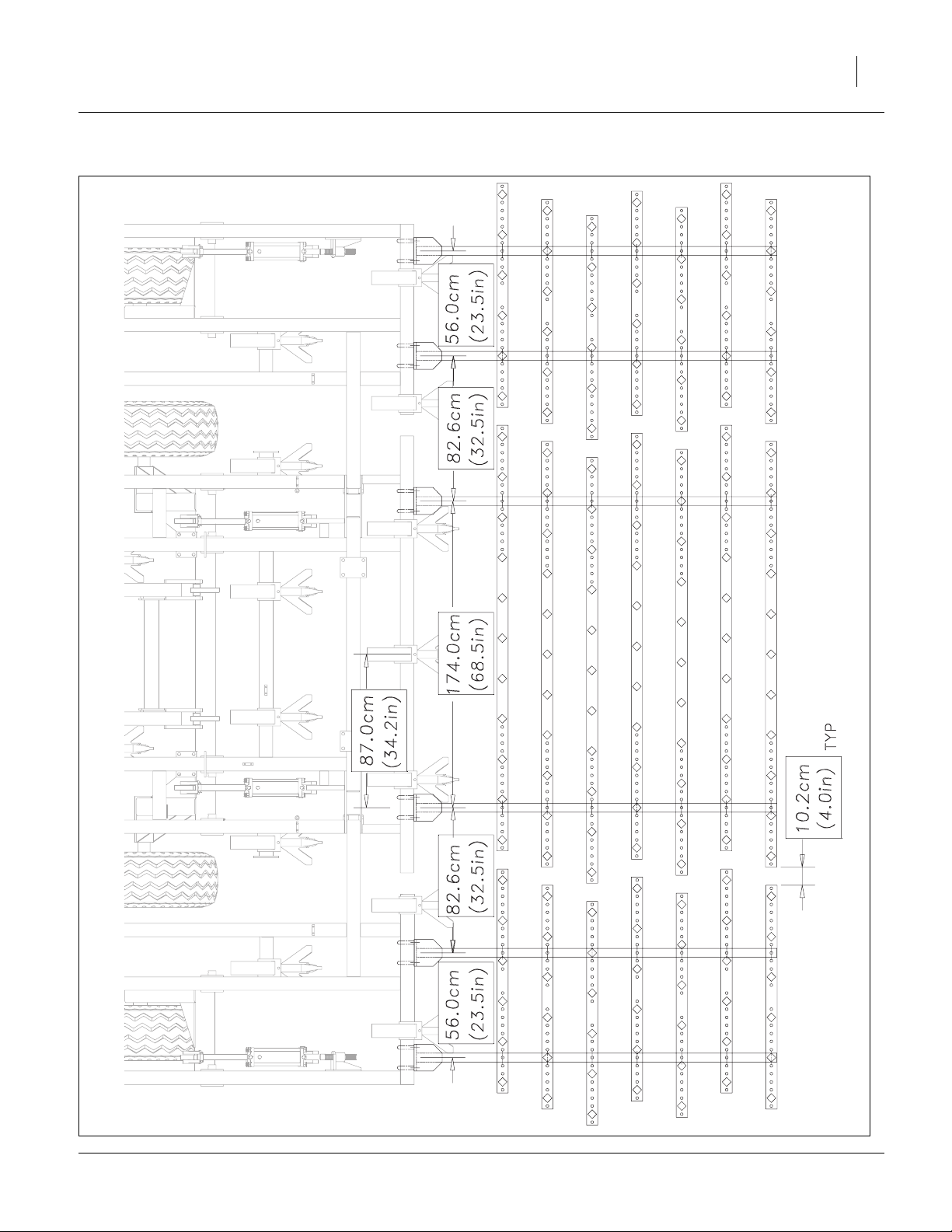
8315DVN HD 3Bar Spike W/Reel Layout .................... 26
8315DVN S7T Layout .................................................. 27
8315DVN S5T HR Layout............................................ 28
8315DVN CH4B Coil Tine Layout................................ 29
8318DVN HD 3Bar Spike W/Reel Layout .................... 30
8318DVN S7T Layout .................................................. 31
8318DVN S5T HR Layout............................................ 32
8318DVN CH4B Coil Tine Layout................................ 33
8321DVN HD 3Bar Spike W/Reel Layout .................... 34
8321DVN S7T Layout .................................................. 35
8321DVN S5T HR Layout............................................ 36
8321DVN CH4B Coil Tine Layout................................ 37
8324DVN HD 3Bar Spike W/Reel Layout .................... 38
8324DVN S7T Layout .................................................. 39
8324DVN S5T HR Layout............................................ 40
8324DVN CH4B Coil Tine Layout................................ 41
Index........................................................................... 43
© Copyright 2006, 2007, 2008, 2009, 2010, 2011, 2012, 2013 All rights Reserved
Great Plains Manufacturing, Inc. provides this publication “as is” without warranty of any kind, either expressed or implied. While every precaution has been
taken in the preparation of this manual, Great Plains Manufacturing, Inc. assumes no responsibility for errors or omissions. Neither is any liability assumed for
damages resulting from the use of the information contained herein. Great Plains Manufacturing, Inc. reserves the right to revise and improve its products as
it sees fit. This publication describes the state of this product at the time of its publication, and may not reflect the product in the future.
11/25/2013 550-466Q
Trademarks of Great Plains Manufacturing, Inc. include: Singulator Plus, Swath Command, Terra-Tine.
Registered Trademarks of Great Plains Manufacturing, Inc. include:
Air-Pro, Clear-Shot, Discovator, Great Plains, Land Pride, MeterCone, Nutri-Pro, Seed-Lok, Solid Stand,
Terra-Guard, Turbo-Chisel, Turbo-Chopper, Turbo Max, Turbo-Till, Ultra-Till, Verti-Till, Whirlfilter, Yield-Pro.
Brand and Product Names that appear and are owned by others are trademarks of their respective owners.
Printed in the United States of America

iv 8315-8324DVN Great Plains Manufacturing, Inc.
550-466Q 11/25/2013
Great Plains Manufacturing, Inc. 1
Important Safety Information
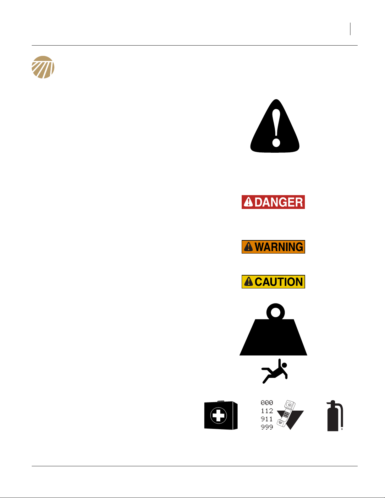
Look for Safety Symbol
The SAFETY ALERT SYMBOL indicates there is a
potential hazard to personal safety involved and extra
safety precaution must be taken. When you see this
symbol, be alert and carefully read the message that follows it. In addition to design and configuration of equipment, hazard control and accident prevention are
dependent upon the awareness, concern, prudence and
proper training of personnel involved in the operation,
transport, maintenance and storage of equipment.
Be Aware of Signal Words
Signal words designate a degree or level of hazard seriousness.
DANGER indicates an imminently hazardous situation
which, if not avoided, will result in death or serious injury.
This signal word is limited to the most extreme situations,
typically for machine components that, for functional purposes, cannot be guarded.
WARNING indicates a potentially hazardous situation
which, if not avoided, could result in death or serious
injury, and includes hazards that are exposed when
guards are removed. It may also be used to alert against
unsafe practices.
CAUTION indicates a potentially hazardous situation
which, if not avoided, may result in minor or moderate
injury. It may also be used to alert against unsafe practices.
Use Adequate Lifting Means
The frame sections and gangs of this machine are
extremely heavy. If using multiple lifters, make sure each
is rated for at least its share of the load.
> 14,000
POUNDS
Prepare for Emergencies
▲ Be prepared if a fire starts
▲ Keep a first aid kit and fire extinguisher handy.
▲ Keep emergency numbers for doctor, ambulance, hospital
and fire department near phone.
11/25/2013 550-466Q
2 8315-8324DVN Great Plains Manufacturing, Inc.
Be Familiar with Safety Decals
▲ Read and understand the “Safety Decals” section of the
Operators Manual.
▲ Read all instructions noted on the decals.
▲ Keep decals clean. Replace damaged, faded and illegible
decals.
Wear Protective Equipment
▲ Wear protective clothing and equipment.
▲ Wear clothing and equipment appropriate for the job. Avoid
loose-fitting clothing.
▲ Because prolonged exposure to loud noise can cause hear-
ing impairment or hearing loss, wear suitable hearing protection such as earmuffs or earplugs.
▲ Because operating equipment safely requires your full
attention, avoid wearing entertainment headphones while
operating machinery.
Avoid High Pressure Fluids
Escaping fluid under pressure can penetrate the skin,
causing serious injury.
▲ Avoid the hazard by relieving pressure before disconnecting
hydraulic lines.
▲ Use a piece of paper or cardboard, NOT BODY PARTS, to
check for suspected leaks.
▲ Wear protective gloves and safety glasses or goggles when
working with hydraulic systems.
▲ If an accident occurs, seek immediate medical assistance
from a physician familiar with this type of injury.
Use Safety Lights and Devices
Slow-moving tractors and towed implements can create
a hazard when driven on public roads. They are difficult
to see, especially at night.
▲ Use flashing warning lights and turn signals whenever driv-
ing on public roads.
Use lights and devices provided with implement
Keep Riders Off Machinery
Riders obstruct the operator’s view. Riders could be
struck by foreign objects or thrown from the machine.
▲ Never allow children to operate equipment.
▲ Keep all bystanders away from machine during operation.
550-466Q 11/25/2013
Great Plains Manufacturing, Inc. Important Safety Information 3
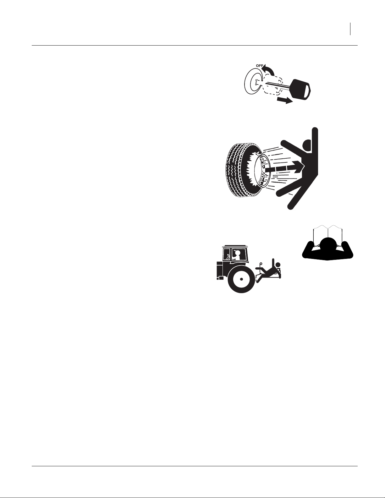
Shutdown and Storage
▲ Lower implement, put tractor in park, turn off engine, and
remove the key.
▲ Secure Discovator using blocks and supports provided.
▲ Detach and store Discovator in an area where children nor-
mally do not play.
Tire Safety
Tire changing can be dangerous and should be performed by trained personnel using correct tools and
equipment.
▲ When inflating tires, use a clip-on chuck and extension hose
long enough for you to stand to one side–not in front of or
over tire assembly. Use a safety cage if available.
▲ When removing and installing wheels, use wheel-handling
equipment adequate for weight involved.
Safety At All Times
Thoroughly read and understand the instructions in this
manual before operation. Read all instructions noted on
the safety decals.
▲ Be familiar with all machine functions.
▲ Operate machinery from the driver’s seat only.
▲ Do not leave machine unattended with tractor engine run-
ning.
▲ Do not stand between the tractor and machine during
hitching.
▲ Keep hands, feet and clothing away from power-driven
parts.
▲ Wear snug-fitting clothing to avoid entanglement with mov-
ing parts.
▲ Watch out for wires, trees, etc., when folding and raising
machine. Make sure all persons are clear of working area.
11/25/2013 550-466Q

4 8315-8324DVN Great Plains Manufacturing, Inc.
Introduction
The DVN Discovator has been designed with care and
built by skilled workers using quality materials. Proper
setup, maintenance, and safe operating practices will help
the customer get years of satisfactory use from the
machine.
Description of Unit
The Series VIII, 8315-8324DVN Discovator is a three-section field finishing, one-pass tillage tool. Working width
ranges from 15 to 24 feet. The implement is designed to
combine discing/slicing, cultivating, harrowing and herbicide incorporation in a single pass. Various finishing
attachments are available to customize your tillage and
residue requirements for your operation.
Models Covered
Figure 1
8324 Discovator
41620
8315DVN 15-Foot 3-section
8318DVN 18-Foot 3-section
8321DVN 21-Foot 3-section
8324DVN 24-Foot 3-section
Document Family
550-466Q-ENG Assembly Manual
550-466Q Pre-Delivery Manual (this document)
550-466M Operator Manual
550-466P Parts Manual
Tools Required
• Basic Hand Tools
• Torque Wrench
• Fork Truck, Overhead Hoist or Loader
Pre-assembly Checklist
1. Before assembling, read and understand “Important
Safety Information” in front part of this manual.
2. Have at least two people on hand while assembling.
3. Make sure area is level and free of obstructions
(preferably an open concrete area).
4. Have all major componets
5. Have all fasteners and pins shipped with Discovator.
550-466Q 11/25/2013
Great Plains Manufacturing, Inc. Introduction 5
Using This Manual
This manual was written to help you assemble and prepare the new machine for the customer. The manual
includes instructions for assembly and setup. Read this
manual and follow the recommendations for safe, efficient and proper assembly and setup.
An operator’s and parts manual is also provided with the
new machine. Read and understand “Important Safety
Information” and “Operating Instructions” in the operator’s manual before assembling the machine. Refer to
the parts manual for proper part’s identification. As a reference, keep the operator’s and part’s manual on hand
while assembling.
The information in this manual is current at printing.
Some parts may change to assure top performance.
Definitions
The following terms are used throughout this manual.
R
A crucial point of information related to the preceding topic.
Read and follow the directions to remain safe, avoid serious
damage to equipment and ensure desired field results.
Note: Useful information related to the preceding topic.
Right-hand and left-hand as used in
this manual are determined by facing
the direction the machine will travel
while in use unless otherwise stated.
An orientation rose in some line art
illustrations shows the directions of: Up,
Back, Left, Down, Front, Right.
R
F
U
B
L
D
L
Figure 2
Right / Left
41597
11/25/2013 550-466Q
6 8315-8324DVN Great Plains Manufacturing, Inc.
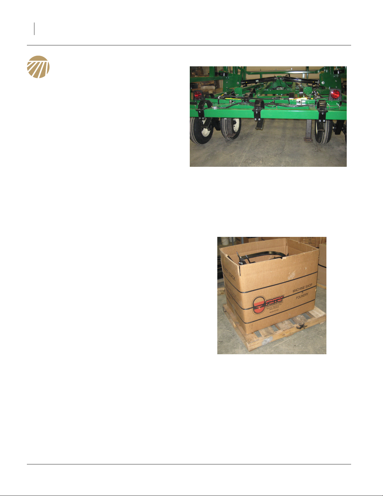
Shipping
The Discovator will be shipped pre-assembled as
shown.
Refer to Figure 3
• The Discovator will be shipped with shipping stands
that will not need to be returned to Great Plains.
• Some models may not have center hub/wheel
assemblies installed.
• Wings will be connected to center frame and folded
in transport positions.
• All hydraulics will be connected and purged.
• Gangs will be pre-assembled and banded together
on pallets.
• Shank mount assemblies will be attached to frames
in proper locations.
• Pre-assembled light brackets will be banded to center frame.
Figure 3
Shipping Machine
41638
Refer to Figure 4
• Shank assemblies will be shipped in a box on a pallet.
• Finishing attachments (if equipped), will be preassembled and banded to pallet.
Figure 4
Shipping Shanks
41639
550-466Q 11/25/2013

Great Plains Manufacturing, Inc. 7
Unloading
Be sure the truck is on level ground, preferably concrete.
Centering componets:
Be sure and center fork truck or chains (overhead hoist) on componets
so they won’t slide and cause injury.
Unload Smaller Items First
Unloading the Discovator is a potentially dangerous
operation.
Reduce risk and complications by first unloading
1. the gangs and finishing attachments
2. the misc. boxes
3. the Discovator
(described in the next section)
Unload Discovator
4. Place these components well out of the manoeuvring area needed for unloading the Discovator.
5. Double-check that all chains and tie-down straps
have been released and stowed.
6. Set parking brake on trailer tractor.
7. Slowly lift the Discovator off trailer bed using two fork
lifts.
8. Stop lifting about 12” above the bed.
9. Have the truck driver slowly pull the trailer straight
out from under the Discovator.
10. Making sure to keep level from front to back and side
to side, slowly lower the Discovator.
11. Lower theDiscovator down until the shipping stands
are about 12” off ground.
12. Remove shipping stands.
13. If machine does not have the center hub/wheel
assembly mounted See “Refer to Figure 5” on
page 8 to install before putting machine completely
on ground.
14. Remove tongue jack from field positions and put in
storage position with foot of jack towards ground.
15. Slowly lower Discovator until it resting on the center
transport tires and front tongue jack.
Unpacking Boxes
Note: Position boxes in area that you can maneuver
components up to machine to assembly.
16. Carefully remove banding from boxes.
17. Carefully remove banding from gangs and finishing
reels.
18. Locate and identify all componets before assembling.
Assembly and Setup Assistance
To order additional copies od pre-delivery instructions or
operator.s and parts manuals, write to the following
address. Include model numbers in all correspondence.
If you do not understand any part of this manual or have
the assembly or setup questions, assistance is available.
Contact:
Product Support
Great Plains Mfg. Inc., Service Department
PO Box 5060
Salina, KS 67402-5060
(800)255-9215
11/25/2013 550-466Q
8 8315-8324DVN Great Plains Manufacturing, Inc.
Assembly
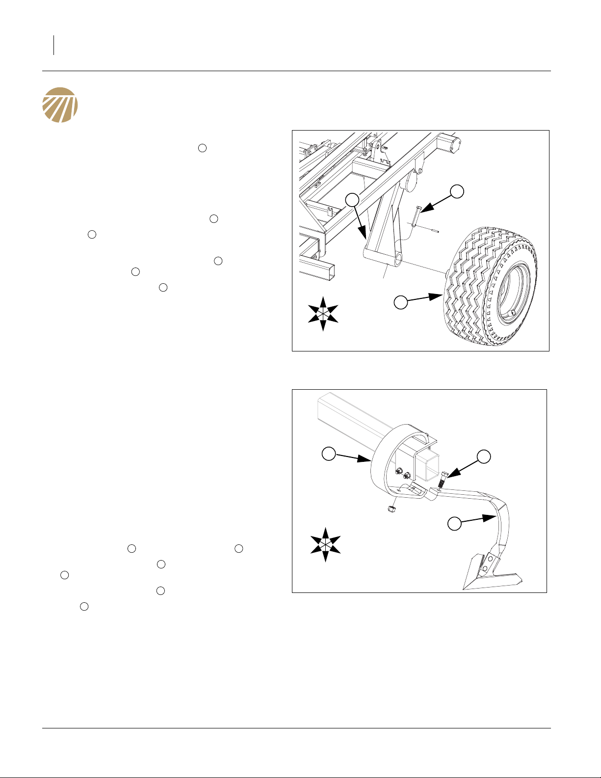
Install Center Hub/Wheel
Note: If center hub/wheel assembly is already installed
on machine go to, See “Refer to Figure 6”on
page 8.
Refer to Figure 5
19. While unloading machine from truck, lower Discovator down close to ground leaving high enough to
install center hub/wheel assembly .
Note: Pin and roll pin will be in manual pak located on
20. Locate center hub/wheel assembly , slide spindle
into torque tube .
21. Align holes, attach pin through holes and secure
with roll pin.
22. Repeat same procedure for other side.
23. Remove screw jack from field position on hitch and
install in storage position on front left side of hitch.
24. Now machine may be carefully lowered down to
ground and let machine rest on tires and jack.
2
hitch.
3
2
1
2
3
1
1
U
R
F
B
L
1
D
Figure 5
Center Hub/Wheel
41687
Note: Attach machine to tractor as shown in “Operator’s
Manual”, to raise machine up and down for ease of
installing components.
Install K-Flex Shanks
Refer to Figure 6
25. If machine is equipped with magnum shanks, See
“Refer to Figure 7” on page 9.
26. The shank mounts will be shipped in correct location
from factory. If something got moved during shipping,
go to layout section of “Operator’s Manual” for proper
placement.
27. Locate shank assemblies from misc. box and remove
the 5/8 x 2 bolt from shank assembly .
28. Slide shank assembly through slot in shank mount
3
and align holes as shown below.
29. Re-attach 5/8 x 2 bolt , secure with 5/8 lock nut.
30. Bolt may be tightened to specs, See “Torque Val-
31. Repeat same procedure for rest of shanks.
1
ues Chart” on page 13.
1 2
2
1
R
F
U
D
3
1
2
B
L
Figure 6
K-Flex Shank
41633
550-466Q 11/25/2013
Great Plains Manufacturing, Inc. Assembly 9
Install Magnum Shanks
Refer to Figure 7
32. The shank mounts will be shipped in correct location
from factory. If something got moved during shipping,
go to the layout section of “Operator’s Manual” for
proper placement.
33. The 1/2 x 1 1/2 bolt will need loosened clear up but
do not take clear out. The 3/4 hex jam nut should
be shipped a little loose so the shank cradle can be
pivoted to install the 5/8 x 2 bolt .
34. Locate shank assemblies from misc. box and remove
the 5/8 x 2 bolt from shank assembly .
35. Slide shank assembly through shank cradle in
shank mount and align holes as shown below.
36. Re-attach 5/8 x 2 bolt , secure with 5/8 lock nut.
37. Bolt may be tightened to specs, See “Torque Val-
Note: Re-tighten 1/2 x 1 1/2 bolt until threads bottom
38. Repeat same procedure for rest of shanks.
2
ues Chart” on page 13.
out. Be sure and tighten 3/4 hex jam nut until
thread bottom out to ensure that hole doesn’t wear
excessively.
1
5
2
2 3
3
4
2
1
5
R
F
U
D
1
2
4
1
3
B
L
Figure 7
Magnum Shank
41634
Attach Disc or Coulter Gangs
Refer to Figure 8
39. The gang hanger assemblies will be shipped
mounted to machine in proper location.
40. The L bundle number will written on a blade of each
disc or coulter gang assembly . See layout section
of “Operator’s Manual” for proper placement.
41. Remove the 1 x 5 1/2 pin and the 3/4 x 2 1/2 pin
from gang hanger assemblies as shown.
42. Move disc or coulter blade assembly into positions
with a fork truck or overhead hoist and align holes.
Re-install the 1 x 5 1/2 pin , secure with the 3/8 x 2
1/4 bolt and lock nut. Re-install the 3/4 x 2 1/2 pin
6 5
washer and cotter pin.
43. All bolts may be tightened to specs, See “Torque Val-
ues Chart” on page 13. Bend over cotter pins.
44. Repeat same procedure for rest of gangs.
4
to spring assemblies , secure with 3/4 flat
2
1
3 6
2
1
3
5
2
4
3
6
1
Figure 8
Disc or Coulter Gangs
41635
11/25/2013 550-466Q
10 8315-8324DVN Great Plains Manufacturing, Inc.
Install Lights and SMV
Refer to Figure 9
45. Remove 1/2 x 1 1/2 bolts from the left and right
hand light bracket assemblies from center frame.
46. Align the holes with the center frame plate and reinstall the 1/2 x 1 1/2 bolts , secure with the 1/2 lock
1
2
3
1
washers and 1/2 nuts.
47. Carefully un-band smv sign assembly from back of
center frame, remove 1/2 u-bolts from smv post.
Mount smv sign assembly to back side of center
4
4
5
frame tube as shown as close to center as possible,
re-install 1/2 u-bolts , secure with 1/2 lock washer
5
and 1/2 nut.
48. Tighten all bolts to specs, See “Torque Values Chart”
on page 13.
5
4
3
2
1
Figure 9
Lights and SMV
41636
550-466Q 11/25/2013
Great Plains Manufacturing, Inc. Assembly 11
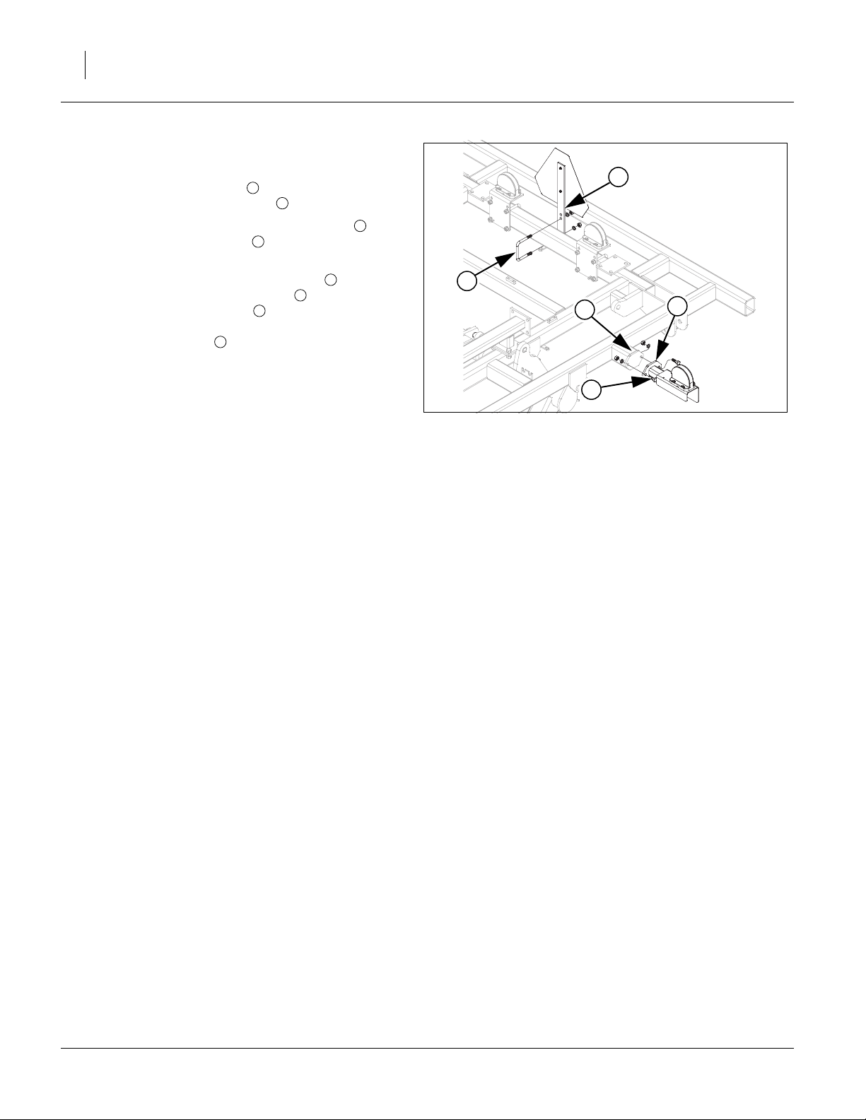
Install Rear Hitch (optional)
Note: The rear tow hitch will be shipped with big compo-
nents banded together and bolts will be in a box.
Carefully un-band the components.
Refer to Figure 10
49. Attach left and right rear hitch arms, rear hitch
truss , rear truss support to center frame using
5/8 x 1 1/2 bolts , 5/8 x 3 1/32 x 5 1/2 u-bolts ,
secure with 5/8 lock washers and 5/8 nuts.
Note: Do not tighten any bolts until every thing is
installed.
50. Now install the rear hitch frame using 5/8 x 1 1/2
bolts , 5/8 x 4 1/32 x 4 1/4 u-bolts , secure with 5/
8 lock washers and 5/8 nuts.
51. The bolt on sleeve assembly with rigid or flex slide
may be fastened using 5/8 x 3 1/32 x 4 1/2 u-bolt ,
secure with 5/8 lock washers and 5/8 nuts.
2 1
4 5
6 7
3
6 8
10
52. Tighten all bolts to specs, See “Torque Values
Chart” on page 13.
53. If machine is equipped with optional rear hitch
accessory kit may be installed as shown in “Parts
Manual”.
54. Route hoses and light harness along hitch and frame
with hose clamps and hose wraps, provided.
Note: Be sure hoses and light harness is fastened
securely so they don’t drag or get pinched.
9
6
4
5
6
1
6
6
6
3
7
10
2
7
8
9
9
Figure 10
Rear Hitch
11/25/2013 550-466Q
41637

12 8315-8324DVN Great Plains Manufacturing, Inc.
Completing Setup
55. If the Discovator is equipped with an optional finishing attachment, refer to “Parts Manual” for parts
breakdown and layout section of “Operator’s Manual”
for proper placement.
56. Once the options are installed, fold the Discovator to
check for clearance and interferences. Slowly fold
Discovator while watching that hoses and wiring har-
nesses do not become pinched or kinked while
watching for interferences.
Note: Double check that all bolts are tightened to specs,
See “Torque Values Chart” on page 13.Consult
the operating instructions, “Operator’s Manual”, for
the first time field adjustments before going to the
field.
550-466Q 11/25/2013

Great Plains Manufacturing, Inc. 13
Appendix - Reference Information
Torque Values Chart
Bolt
Size
in-tpi
1
⁄4-20
1
⁄4-28
5
⁄16-18
5
⁄16-24
3
⁄8-16
3
⁄8-24
7
⁄16-14
7
⁄16-20
1
⁄2-13
1
⁄2-20
9
⁄16-12
9
⁄16-18
5
⁄8-11
5
⁄8-18
3
⁄4-10
3
⁄4-16
7
⁄8-9
7
⁄8-14
1-8
1-12
1
1
⁄8-7
1
1
⁄8-12
1
⁄4-7
1
1
⁄4-12
1
3
⁄8-6
1
3
1
⁄8-12
1
1
⁄2-6
1
1
⁄2-12
Bolt Head Identification
Grade 2 Grade 5 Grade 8 Class 5.8 Class 8.8 Class 10.9
a
b
d
N-m
ft-lb
7.4 11 16
8.5 13 18
15 24 33
17 26 37
27 42 59
31 47 67
43 67 95
49 75 105
66 105 145
75 115 165
95 150 210
105 165 235
130 205 285
150 230 325
235 360 510
260 405 570
225 585 820
250 640 905
340 875 1230
370 955 1350
480 1080 1750
540 1210 1960
680 1520 2460
750 1680 2730
890 1990 3230
1010 2270 3680
1180 2640 4290
1330 2970 4820
N-m N-m
5.6 8 12
61014 5 811
11 17 25 12 19 27
13 19 27 13 21 29
20 31 44 24 39 53
22 35 49 29 45 62
32 49 70 42 67 93
36 55 78 44 70 97
49 76 105 66 77 105
55 85 120 68 105 150
70 110 155 73 115 160
79 120 170 105 165 230
97 150 210 115 180 245
110 170 240 145 230 300
170 265 375 165 260 355
190 295 420 205 325 450
165 430 605 230 480 665
185 475 670 355 560 780
250 645 910 390 610 845
275 705 995 705 1120 1550
355 795 1290 785 1240 1710
395 890 1440 1270 1950 2700
500 1120 1820 1380 2190 3220
555 1240 2010
655 1470 2380
745 1670 2710
870 1950 3160
980 2190 3560
Bolt Head Identification
Bolt
Size
ft-lb ft-lb ft-lb ft-lb ft-lb
mm x pitch
M 5 X 0.8
M 6 X 1
M 8 X 1.25
M 8 X 1
M10 X 1.5
M10 X 0.75
M12 X 1.75
M12 X 1.5
M12 X 1
M14 X 2
M14 X 1.5
M16 X 2
M16 X 1.5
M18 X 2.5
M18 X 1.5
M20 X 2.5
M20 X 1.5
M24 X 3
M24 X 2
M30 X 3.5
M30 X 2
M36 X 3.5
M36 X 2
a. in-tpi = nominal thread diameter in inches-threads per inch
b. N· m = newton-meters
c. mm x pitch = nominal thread diameter in mm x thread pitch
d. ft-lb = foot pounds
c
5.8 8.8 10.9
N-m N-m N-m
357
71115
17 26 36
18 28 39
33 52 72
39 61 85
58 91 125
60 95 130
90 105 145
92 145 200
99 155 215
145 225 315
155 240 335
195 310 405
220 350 485
280 440 610
310 650 900
480 760 1050
525 830 1150
960 1510 2100
1060 1680 2320
1730 2650 3660
1880 2960 4100
946
Torque tolerance + 0%, -15% of torquing values. Unless otherwise specified use torque values listed above.
25199m
25199
Disc or Coulter Gang Bolt Torque 1 1/2”-6 650-750 Foot-pounds (175 lbs on 4’ cheater).
11/25/2013 550-466Q
14 8315-8324DVN Great Plains Manufacturing, Inc.
Tire Inflation Chart
Tire Size Inflation Tire Warranty Information
6.70 x 15”
4-Ply
12.5L x 16.5”
Load G Galaxy
32-15.5 x 16.5”
Load G Galaxy
380/55R x 16.5
Load F RI
221 kPa
32 psi
724 kPa
105psii
621 kPa
793 psi
503 kPa
73 psi
All tires are warranted by the original manufacturer of
the tire. Tire warranty information is found online at the
manufacturer’s web sites listed below. For assistance or
information, contact your nearest Authorized Farm Tire
Retailer.
Manufacturer
Firestone
Gleason
Titan
Web site
www.firestoneag.com
www.gleasonwheel.com
www.titan-intl.com
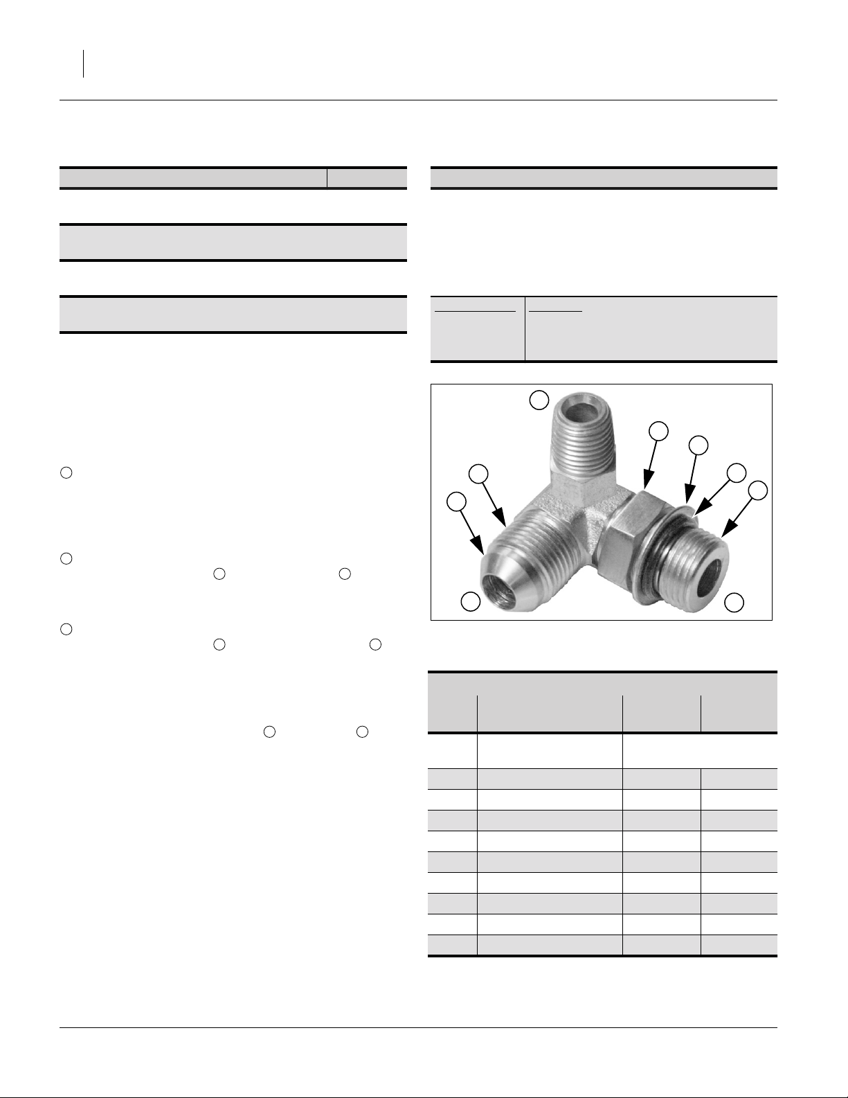
Hydraulic Connectors and Torque
Refer to Figure 11 (a hypothetical fitting)
Leave any protective caps in place until immediately prior
to making a connection.
1
NPT - National Pipe Thread
Note tapered threads, no cone/flare, and no O-ring.
Apply liquid pipe sealant for hydraulic applications.
Do not use tape sealant, which can clog a filter and/or
plug an orifice.
2
JIC - Joint Industry Conference (SAE J514)
Note straight threads and the 37° cone on
“M” fittings (or 37° flare on “F” fittings).
Use no sealants (tape or liquid) on JIC fittings.
3
ORB - O-Ring Boss (SAE J514)
Note straight threads and elastomer O-Ring .
Prior to installation, to prevent abrasion during tightening, lubricate O-Ring with clean hydraulic fluid.
Use no sealants (tape or liquid) on ORB fittings.
ORB fittings that need orientation, such as the ell
depicted, also have a washer and jam nut
(“adjustable thread port stud”). Back jam nut away
from washer. Thread fitting into receptacle until
O-Ring contacts seat. Unscrew fitting to desired
orientation. Tighten jam nut to torque specification.
4 5
5 7
8 9
5
Dash
Size
-4
-5
-5
-5
-6
-6
-6
-8
-8
-8
1
9
8
4
2
Figure 11
Hydraulic Connector ID
Fittings Torque Values
Fitting N-m Ft-Lbs
1
⁄4-18 NPT 1.5-3.0 turns past finger
tight
1
⁄2-20 JIC 19-20 14-15
1
⁄2-20 ORB w/jam nut 12-16 9-12
1
⁄2 -20 ORB straight 19-26 14-19
5
⁄16-18 JIC 24-27 18-20
5
⁄16-18 ORB w/jam nut 16-22 12-16
5
⁄16-18 ORB straight 24-33 18-24
3
⁄4 -16 JIC 37-53 27-39
3
⁄4 -16 ORB w/jam nut 27-41 20-30
3
⁄4-16 ORB straight 37-58 27-43
7
5
3
31282
550-466Q 11/25/2013

Great Plains Manufacturing, Inc. Appendix - Reference Information 15
Lift and Gang Hydraulic Layout
41542
11/25/2013 550-466Q

16 8315-8324DVN Great Plains Manufacturing, Inc.
Fold Hydraulic Layout
41543
550-466Q 11/25/2013

Great Plains Manufacturing, Inc. Appendix - Reference Information 17
Retract Layout
41920
11/25/2013 550-466Q

18 8315-8324DVN Great Plains Manufacturing, Inc.
8315D Machine Layout, Disc
43208
550-466Q 11/25/2013

Great Plains Manufacturing, Inc. Appendix - Reference Information 19
8315C Machine Layout, Coulter
43207
11/25/2013 550-466Q
20 8315-8324DVN Great Plains Manufacturing, Inc.
8318D Machine Layout, Disc
43209
550-466Q 11/25/2013

Great Plains Manufacturing, Inc. Appendix - Reference Information 21
8318C Machine Layout, Coulter
43210
11/25/2013 550-466Q
22 8315-8324DVN Great Plains Manufacturing, Inc.
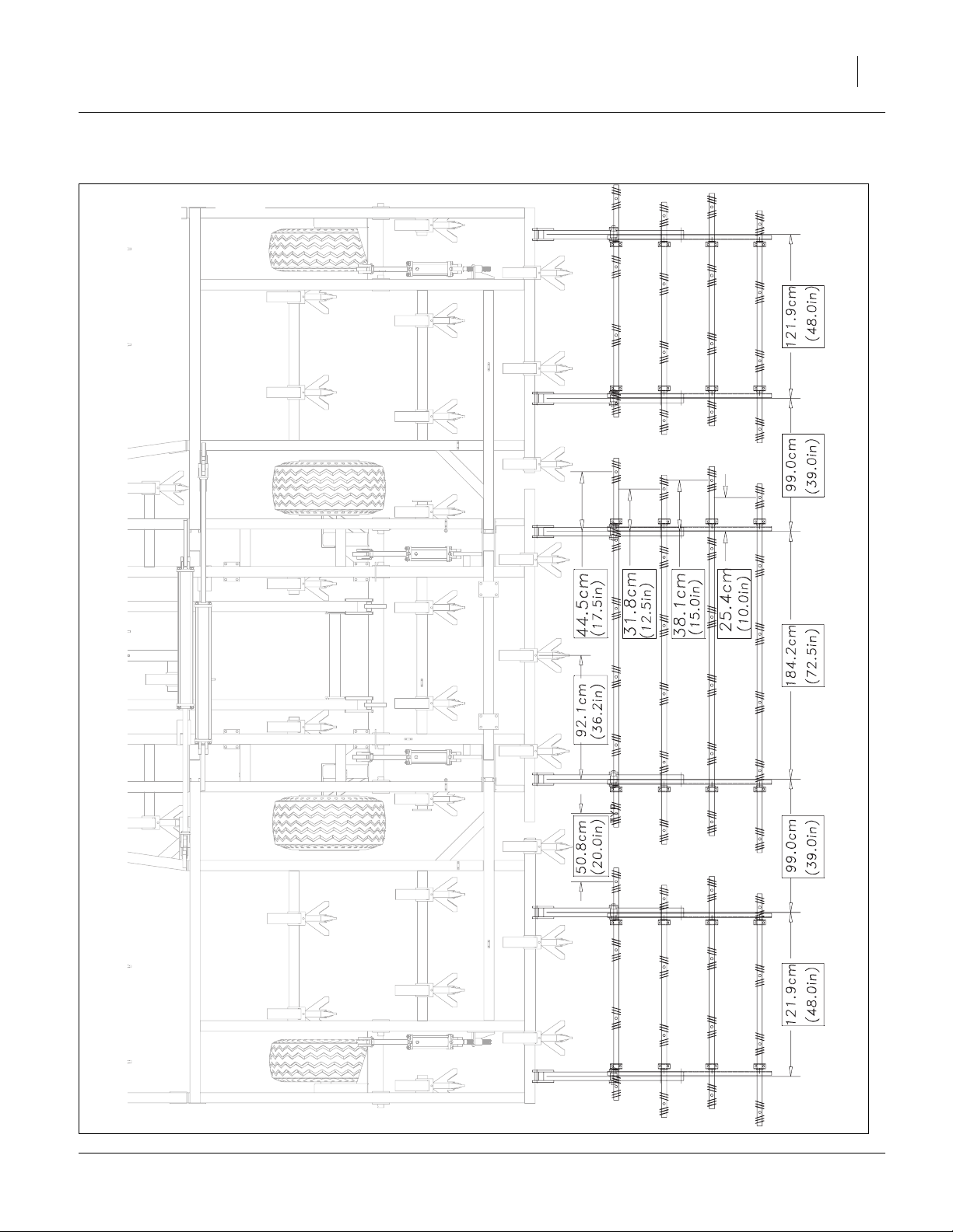
8321D Machine Layout, Disc
43200
550-466Q 11/25/2013
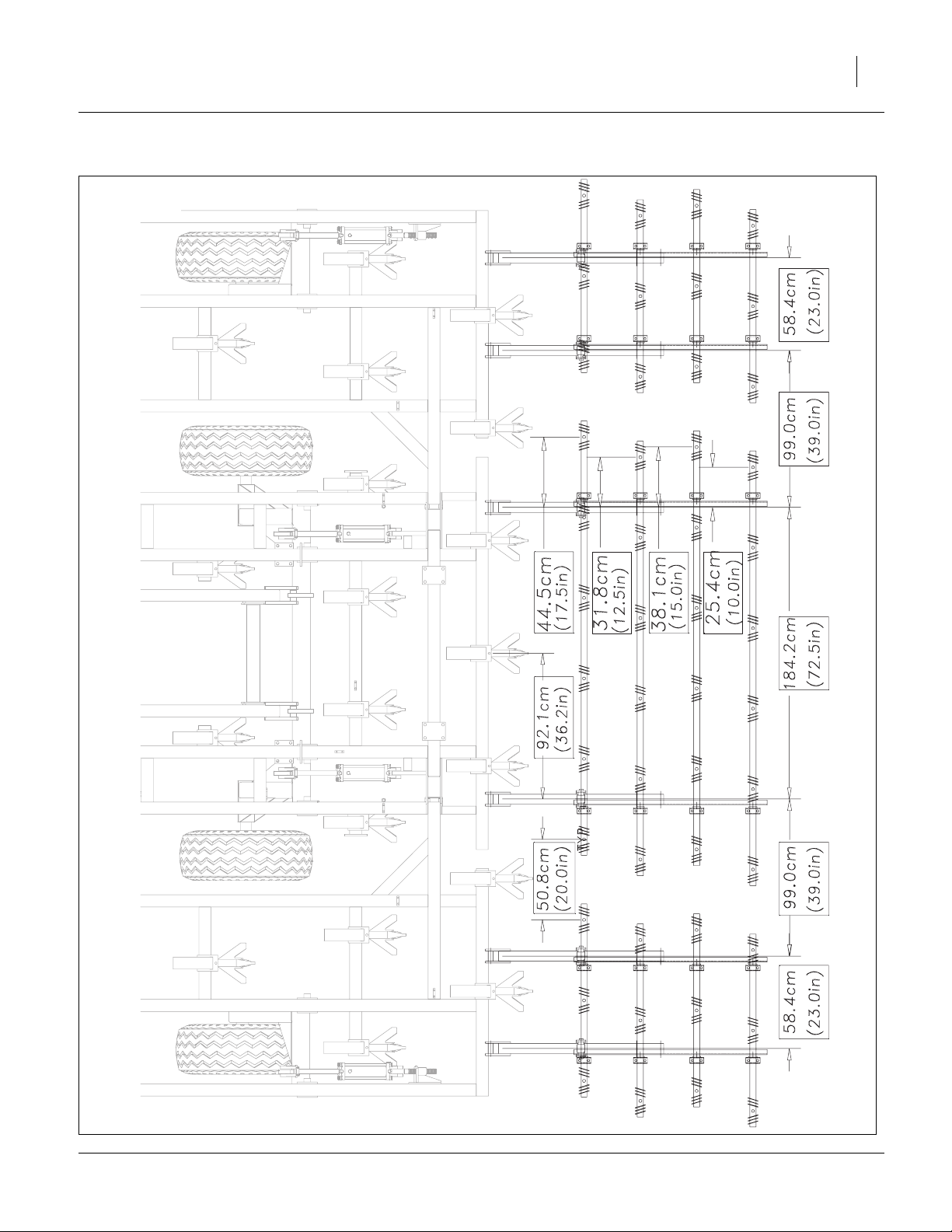
Great Plains Manufacturing, Inc. Appendix - Reference Information 23
8321C Machine Layout, Coulter
41521
11/25/2013 550-466Q

24 8315-8324DVN Great Plains Manufacturing, Inc.
8324D Machine Layout, Disc
41526
550-466Q 11/25/2013
Great Plains Manufacturing, Inc. Appendix - Reference Information 25
8324C Machine Layout, Coulter
41522
11/25/2013 550-466Q

26 8315-8324DVN Great Plains Manufacturing, Inc.
8315DVN HD 3Bar Spike W/Reel Layout
42947
550-466Q 11/25/2013
Great Plains Manufacturing, Inc. Appendix - Reference Information 27
8315DVN S7T Layout
41556
11/25/2013 550-466Q

28 8315-8324DVN Great Plains Manufacturing, Inc.
8315DVN S5T HR Layout
41557
550-466Q 11/25/2013

Great Plains Manufacturing, Inc. Appendix - Reference Information 29
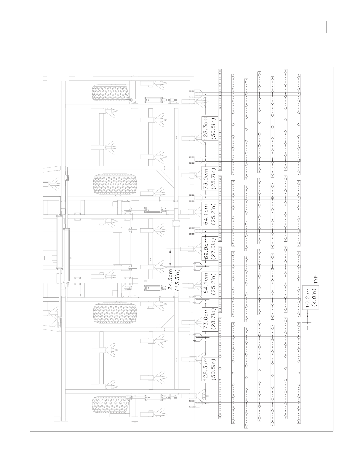
8315DVN CH4B Coil Tine Layout
41558
11/25/2013 550-466Q

30 8315-8324DVN Great Plains Manufacturing, Inc.
8318DVN HD 3Bar Spike W/Reel Layout
42948
550-466Q 11/25/2013

Great Plains Manufacturing, Inc. Appendix - Reference Information 31
8318DVN S7T Layout
41561
11/25/2013 550-466Q

32 8315-8324DVN Great Plains Manufacturing, Inc.
8318DVN S5T HR Layout
41562
550-466Q 11/25/2013
Great Plains Manufacturing, Inc. Appendix - Reference Information 33
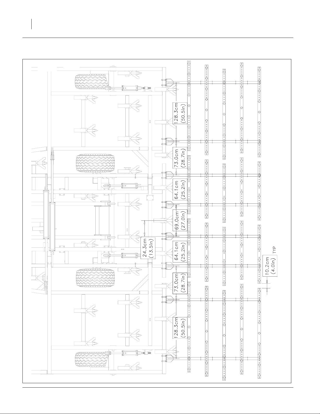
8318DVN CH4B Coil Tine Layout
41563
11/25/2013 550-466Q

34 8315-8324DVN Great Plains Manufacturing, Inc.
8321DVN HD 3Bar Spike W/Reel Layout
42948
550-466Q 11/25/2013
Great Plains Manufacturing, Inc. Appendix - Reference Information 35
8321DVN S7T Layout
41566
11/25/2013 550-466Q
36 8315-8324DVN Great Plains Manufacturing, Inc.
8321DVN S5T HR Layout
41567
550-466Q 11/25/2013
Great Plains Manufacturing, Inc. Appendix - Reference Information 37
8321DVN CH4B Coil Tine Layout
41568
11/25/2013 550-466Q

38 8315-8324DVN Great Plains Manufacturing, Inc.
8324DVN HD 3Bar Spike W/Reel Layout
42950
550-466Q 11/25/2013

Great Plains Manufacturing, Inc. Appendix - Reference Information 39
8324DVN S7T Layout
41571
11/25/2013 550-466Q

40 8315-8324DVN Great Plains Manufacturing, Inc.
8324DVN S5T HR Layout
41572
550-466Q 11/25/2013

Great Plains Manufacturing, Inc. Appendix - Reference Information 41
8324DVN CH4B Coil Tine Layout
41573
11/25/2013 550-466Q

42 8315-8324DVN Great Plains Manufacturing, Inc.
550-466Q 11/25/2013

Great Plains Manufacturing, Inc. 43
Index
A
address, Great Plains ........................ 7
B
banding .............................................. 7
C
CAUTION, defined ............................. 1
center hub/wheel assembly ............... 8
center transport tires .......................... 7
chains and tie-downs ......................... 7
children .............................................. 2
clothing ............................................... 2
componets ......................................... 7
contact Great Plains ........................... 7
covered models .................................. 4
D
DANGER, defined .............................. 1
decals ................................................. 2
definitions ........................................... 5
directions ..................................... 5
, 6
E
electrical hookup ................................ 8
email, Great Plains ............................. 7
F
finishing attachments ..........4, 6, 12
fire ...................................................... 1
fork truck ............................................ 7
G
gangs .......................................... 6, 7
Gleason ............................................ 14
H
headphones ....................................... 2
hearing ............................................... 2
high pressure fluids ............................ 2
hydraulic connectors ........................ 14
hydraulic safety .................................. 2
hydraulics ........................................... 6
I
IMPORTANT!, defined ........................ 5
J
jack .............................................. 7, 8
JIC .................................................... 14
Joint Industry Conference ................ 14
J514 ................................................. 14
K
kPa ................................................... 14
L
layout
CH4B Coil Tine
8315DVN ............................. 29
8318DVN ............................. 33
8321DVN ............................. 37
8324DVN ............................. 41
HD 3 Bar Spike W/Reel
8315DVN ............................. 26
8318DVN ............................. 30
8321DVN ............................. 34
8324DVN ............................. 38
hydraulic
fold ....................................... 16
lift and gang ......................... 15
retract ................................... 17
machine
8315C .................................. 19
8315D .................................. 18
8318C .................................. 21
8318D .................................. 20
8321C .................................. 23
8321D .................................. 22
8324C .................................. 25
8324D .................................. 24
S5T Spike Drag
8315DVN ............................. 28
8318DVN ............................. 32
8321DVN ............................. 36
8324DVN ............................. 40
S7T Spike Drag
8315DVN ............................. 27
8318DVN ............................. 31
8321DVN ............................. 35
8324DVN ............................. 39
leaks .................................................. 2
left-hand, defined ............................... 5
level ................................................... 7
lifters .................................................. 1
light brackets ..............................6
lights .................................................. 2
, 10
M
medical assistance ............................ 2
misc boxes ......................................... 7
N
National Pipe Thread ....................... 14
Note, defined ..................................... 5
NPT ................................................. 14
O
ORB .................................................14
orientation rose ........................... 5
O-Ring Boss ..................................... 14
, 6
P
parking brakes ....................................7
protective equipment .......................... 2
psi .....................................................14
R
rear tow hitch ....................................11
riders .................................................. 2
right-hand, defined ............................. 5
rose, orientation .......................... 5
, 6
S
SAE J514 ......................................... 14
safety symbol ..................................... 1
shank assemblies ...............................6
shank mount assemblies ....................6
shipping stands ........................... 6
shutdown ............................................ 3
storage ............................................... 3
support ............................................... 7
symbol, safety .................................... 1
, 7
T
tables
document family ........................... 4
fittings torque ..............................14
models covered ............................4
tire inflation .................................14
torque values ..............................13
tire inflation ....................................... 14
tires ....................................................3
Titan ................................................. 14
torque value chart ............................13
trailer bed ........................................... 7
truck driver .........................................7
U
URLs, tires .......................................14
W
WARNING, defined ............................1
wings ..................................................6
Numerics
550-466M, manual ............................. 4
550-466P, manual ...............................4
550-466Q-ENG, manual ....................4
550-466Q, manual .............................4
11/25/2013 550-466Q

44 8315-8324DVN Great Plains Manufacturing, Inc.
550-466Q 11/25/2013


Great Plains Manufacturing, Inc.
Corporate Office: P.O. Box 5060
Salina, Kansas 67402-5060 USA
 Loading...