

Great Plains Discharge Elbow Kit Hypro Pumps User Manual
Great Plains Mfg., Inc.
Discharge Elbow Kit
Hypro Pumps
Used with:
• Model year 2006 and earlier pumps
General Information
These instructions explain how to install the Discharge
Elbow Kit. This kit replaces both original OEM single-part
elbows, and current 3-part elbows. The 3-part assembly
provides enhanced resistance to caustic chemicals.
These instructions apply to:
Option Package Part Number
HYPRO PUMP DISCHARGE
ELBOW KIT
These instructions presume that the elbow to be
replaced is the older single-part style.
The existing flange or elbow may be attached to the
pump with removable nuts on threaded studs, or removable bolts and nuts. These instructions presume nuts on
studs.
Note: Be careful not to drop or misplace the fasteners.
They are likely in metric sizing, and due to supplier
component changes over time, this manual is
unable to precisely specify their call sizes.
407-188A
Installation Instructions 1
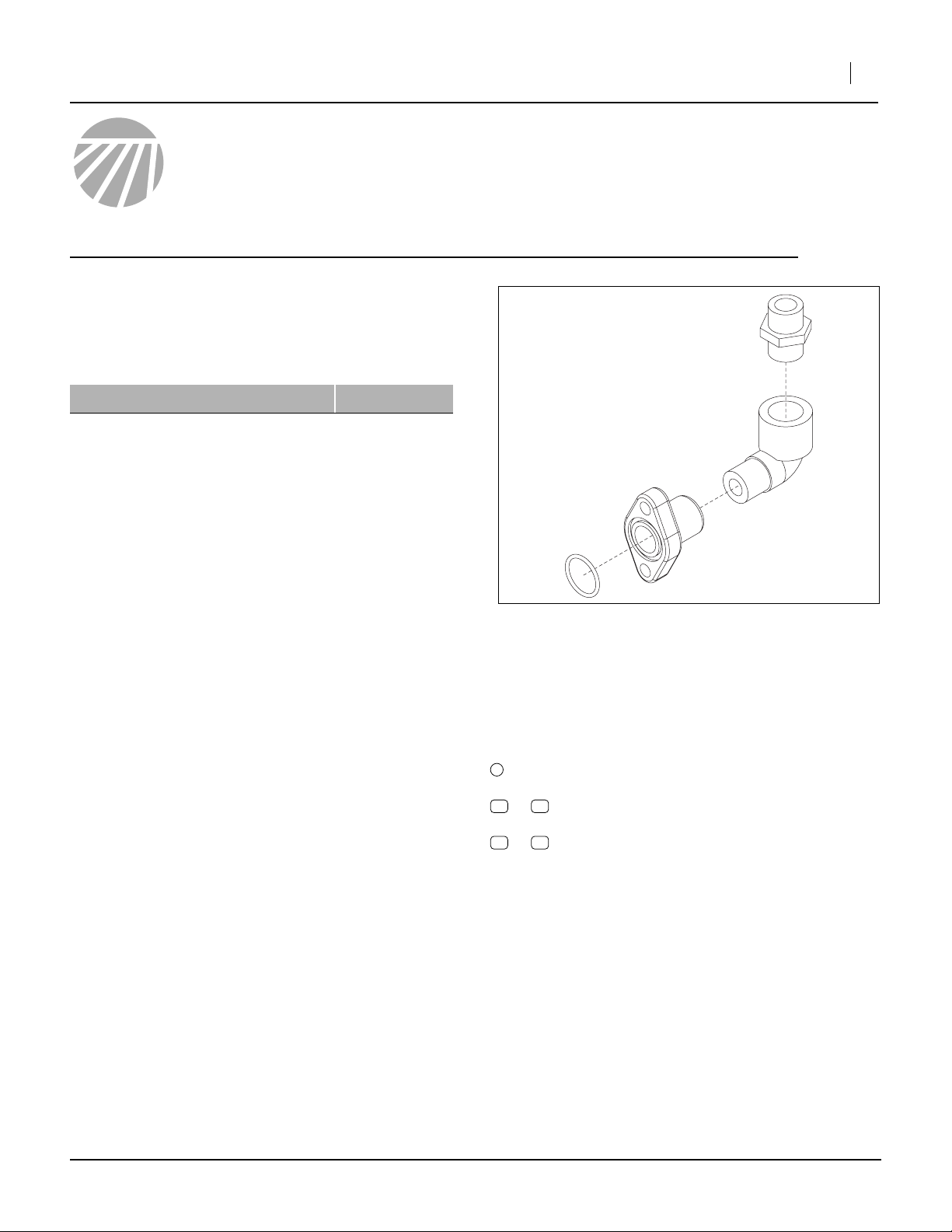
Figure 1
Update Kit Components
26103
Before You Start
Each kit converts one pump.
For each kit, inventory the contents per the “Parts List”
on page 4.
Review the instructions, to make sure the steps are
understood and what tools are expected.
Have the following items at hand:
• Appropriate safety equipment, such as chemical
gloves, for working with the fertilizer chemicals most
recently pumped.
• Suitable location and equipment for flushing the fertilizer line at the pump.
• Original or updated Parts Manual for your implement
• Basic hand tools
• Pipe thread sealant suitable for polypropylene, such
as Rectorseal or Teflon® PTFE tape.
Notations and Conventions
1
callouts identify components in the currently
referenced Figure or Figures
15
11
to callouts reference new parts from the list on
page 4
51 55
to callouts reference existing parts. The
descriptions match those in your Parts manual.
©Copyright 2007 Printed 03/01/2007 407-189M
2 Discharge Elbow Kit
Installation
Flush The Pump
1. Move the implement to a location suitable for flushing the fertilizer system, such as the field most
recently fertilized.
2. Refer to the implement Operator’s manual, and flush
the fertilizer system with water (or if freezing
weather is possible before next use, with RV antifreeze).
3. If necessary, move the implement again, to a dry
well-lighted location suitable for disassembly.
4. Raise and unfold the implement. Lower it, or if you
prefer to leave it raised, install lift cylinder locks.
5. Secure the tractor.
Disconnect Boom Line
Great Plains Mfg., Inc.
!
CAUTION
Because the discharge line usually exits upward from the
pump, it is almost certain to contain a significant amount of
fluid. Wear appropriate protective gear and ensure that the
resulting spillage is contained, such as with a bucket under
the pump.
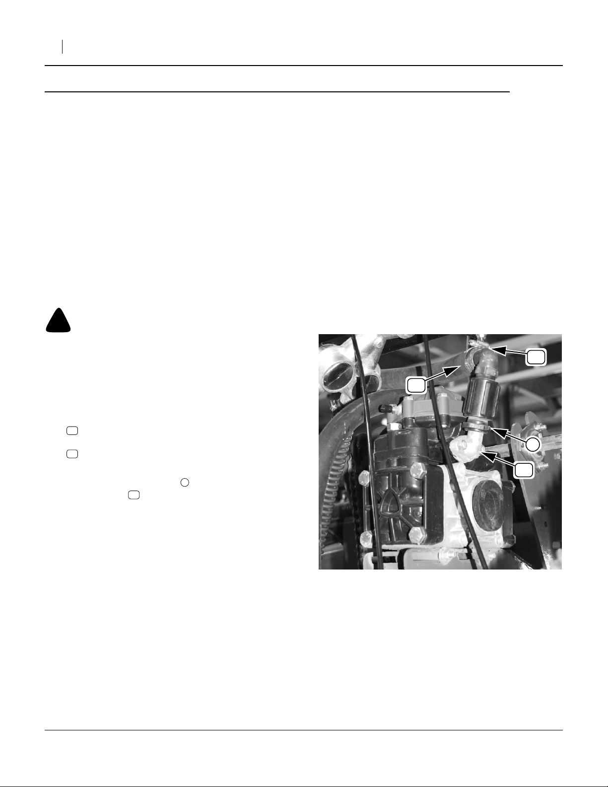
Refer to Figure 2
6. Loosen the:
52
CLAMP WRM DRV #16 SS (.68-1.5)
and disconnect the:
53
HOSE 1 ID 200PSI EPDM.
Save these components.
7. Loosen the adaptor stack attached to the discharge elbow .
Remove and save it the adaptor stack.
It is not necessary to further disassemble the
stack.
51
1
53
Figure 2
Disconnect Discharge Line
52
1
51
26104
407-189M 03/01/2007
 Loading...