

Page 1

OPERATOR’S MANUAL
Safety Notices ..................................................................................................... 1
Introduction ......................................................................................................... 3
System Overview .............................................................................................................. 3
Installation and Setup ......................................................................................... 5
Console Mounting ............................................................................................................. 5
Console Harness Installation ............................................................................................ 6
Power Connection ............................................................................................................. 7
Implement Harness/Module Connection ........................................................................... 9
Module Order ................................................................................................................................... 9
Module Installation ........................................................................................................................... 9
Module Setup Examples ................................................................................................................ 12
Connecting Sensors to Modules .................................................................................................... 14
Hopper Level Sensors .................................................................................................................... 15
Harnesses .......................................................................................................................18
12 Row Harness ............................................................................................................................. 18
16 Row Harness ............................................................................................................................. 18
Shaft Speed Module Harness ........................................................................................................ 19
RS485 Extension Harness ............................................................................................................. 19
Startup ............................................................................................................... 21
Switchpad Overview ....................................................................................................... 21
On/Off ............................................................................................................................................. 21
Alarm .............................................................................................................................................. 21
Setup .............................................................................................................................................. 21
Min Avg Max Scan ......................................................................................................................... 21
Select Row ...................................................................................................................................... 21
Select .............................................................................................................................................. 22
Set................................................................................................................................................... 22
Start Stop Reset ............................................................................................................................. 22
Back ................................................................................................................................................ 22
Operate 1 ....................................................................................................................................... 22
Operate 2 ....................................................................................................................................... 23
Operate 3 ....................................................................................................................................... 23
Setup Mode ..................................................................................................................... 24
Setup Constants ............................................................................................................................. 24
Seed Flow Alarm Adjustment ......................................................................................................... 26
Population Hi Limit ......................................................................................................................... 27
Population Lo Limit ......................................................................................................................... 27
Row Width ...................................................................................................................................... 27
Implement Width ............................................................................................................................ 28
Ground Speed Source ................................................................................................................... 28
Distance Calibration ....................................................................................................................... 28
Automatic Configuration ................................................................................................................. 29
Split Row Configuration .................................................................................................................. 30
Number of Seed Modules .............................................................................................................. 31
Row Status ..................................................................................................................................... 32
Total Number Of Rows Configured ................................................................................................ 33
Number of Fan Speed Sensors ...................................................................................................... 33
Number of Shaft Speed Sensors ...................................................................................................35
Seed Manager SE ®
11001-1359A-200810
/I
Page 2

OPERATOR’S MANUAL
Setup Mode Continued ...................................................................................... 37
Number of Hopper Level Sensors ..................................................................................................37
Number of Pressure Sensors ......................................................................................................... 38
Blockage Mode Configuration ........................................................................................................ 39
Population Filter .............................................................................................................................. 40
Population Scaling Factor ............................................................................................................... 41
Sensor/Module Self-Test ................................................................................................................ 41
English/Metric Units ........................................................................................................................ 42
Customer Setup Constants ............................................................................................................ 42
Operation .......................................................................................................... 45
Operate Mode ................................................................................................................. 45
Run Hours ...................................................................................................................... 45
Population ....................................................................................................................... 46
Population Scan ............................................................................................................. 46
Population Min Avg Max ................................................................................................................. 47
Population Select Row ................................................................................................................... 47
Seed Spacing ................................................................................................................................. 48
Ground Speed ................................................................................................................................ 48
Fan Speed ...................................................................................................................................... 49
Shaft Speed .................................................................................................................................... 49
Pressure ......................................................................................................................................... 50
Area Accumulator ........................................................................................................................... 50
Seed Count ..................................................................................................................................... 51
Distance Accumulator ..................................................................................................................... 51
Speed Area Mode ........................................................................................................................... 52
Alarms ............................................................................................................... 53
All Rows Failed ............................................................................................................................... 54
Rows Failed .................................................................................................................................... 54
Distance Sensor Failed .................................................................................................................. 54
Population Hi Limit Warning ........................................................................................................... 55
Population Lo Limit Warning ........................................................................................................... 56
Fan Speed Hi Limit Warning ........................................................................................................... 56
Fan Speed Lo Limit Warning .......................................................................................................... 57
Shaft Speed Hi Limit Warning ........................................................................................................ 57
Shaft Speed Lo Limit Warning ........................................................................................................ 58
Pressure Hi Limit Warning .............................................................................................................. 58
Pressure Lo Limit Warning ............................................................................................................. 58
Hopper Lo Warning ........................................................................................................................ 59
Battery Voltage Warning ................................................................................................................. 60
Self Test Error Codes ....................................................................................... 61
Connector Pinouts .......................................................................................................... 65
Setup Record Sheet ....................................................................................................... 66
Setup Record Sheet ....................................................................................................... 67
Warranty.............................................................................................................. 69
II /
Seed Manager SE
11001-1359A-200810
Page 3
OPERATOR’S MANUAL
SAFETY NOTICES
Safety notices are one of the primary ways to call attention to potential
hazards.
This Safety Alert Symbol identifies important safety
messages in this manual. When you see this symbol,
carefully read the message that follows. Be alert to
the possibility of personal injury or death.
Use of the word WARNING indicates a potentially hazardous
situation which, if not avoided, could result in death or serious
injury.
Use of the word CAUTION with the Safety Alert Symbol indicates a
potentially hazardous situation which, if not avoided, may result in
minor or moderate injury.
Use of the word CAUTION without the safety alert symbol
indicates a potentially hazardous situation which, if not avoided,
may result in equipment damage.
Seed Manager SE®
11001-1359A-200810
SAFETY NOTICES / 1
Page 4

OPERATOR’S MANUAL
2 / SAFETY NOTICES
Seed Manager SE
11001-1359A-200810
Page 5

OPERATOR’S MANUAL
INTRODUCTION
SYSTEM OVERVIEW
The Seed Manager® SE System monitors up to ninety six (96) seed rows,
two (2) fan (RPM) inputs, three (3) shaft speed (RPM) inputs, two (2)
pressure inputs, seven (7) hopper level inputs, and (1) ground speed input.
It is compatible with DICKEY-john standard and Hi-Rate seed sensors.
Implement configuration data is stored in nonvolatile memory retaining
information even when disconnected from the tractor battery.
Figure 1
SeedManager
®
SE Console
Seed Manager SE®
11001-1359A-200810
INTRODUCTION / 3
Page 6

OPERATOR’S MANUAL
4 / INTRODUCTION
Seed Manager SE
11001-1359A-200810
Page 7
OPERATOR’S MANUAL
INSTALLATION AND SETUP
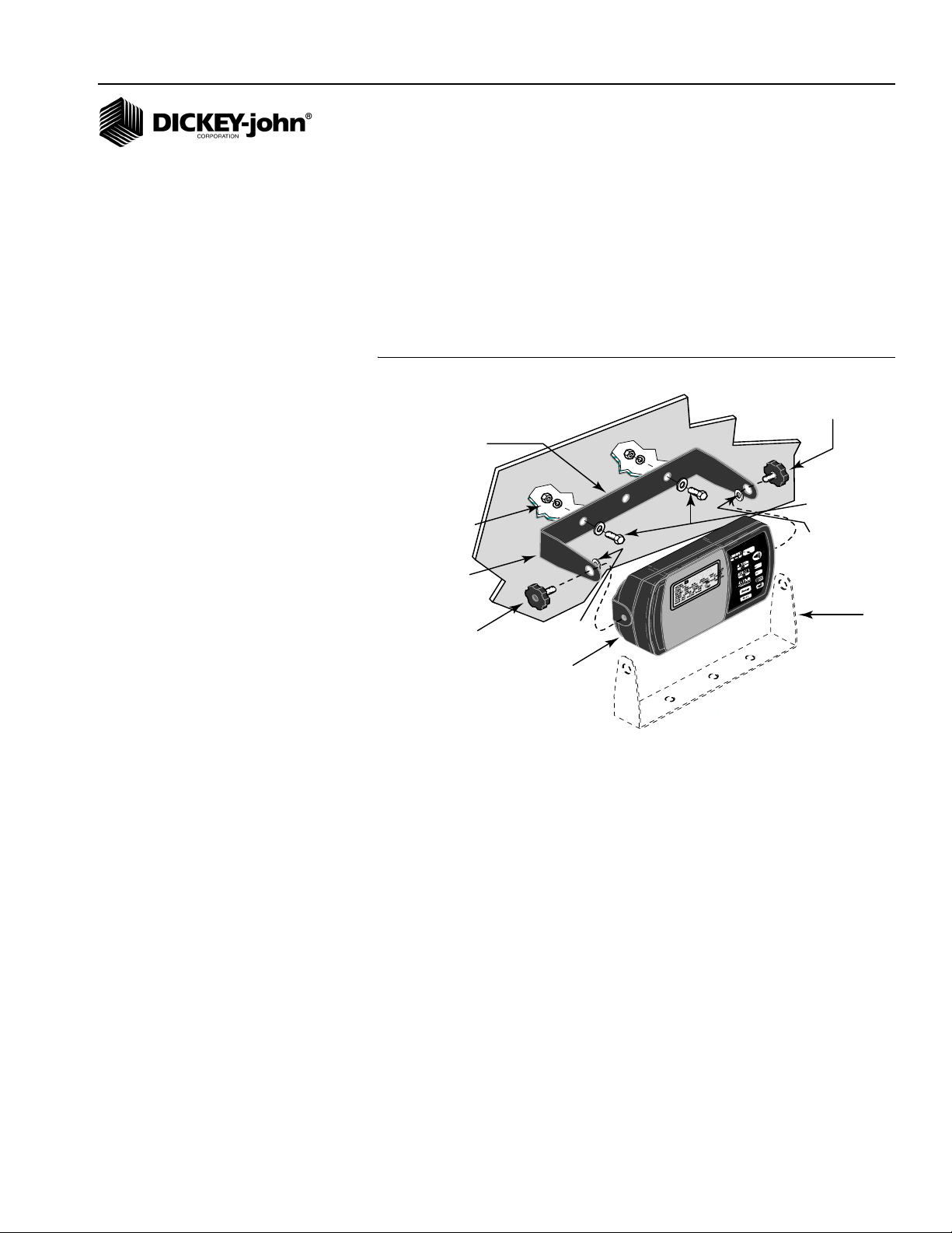
CONSOLE MOUNTING
The console should be mounted inside the tractor cab in a location
accessible to the operator but does not obstruct the driving view. (Figure 2)
depicts a typical console mount.
Figure 2
Typical Console Mounting using the U-bracket and hardware
Knob
Screw
U-Bracket
1/4-20 x 3/4 Inch
Hex Bolts &
1/4
-20 Nuts
and Lockwasher
Flat washers
Rubber
Washer
U-Bracket
Knob
Screw
Rubber
Washer
Console
(Preferred Mounting
U-Bracket
Position)
MOUNTING STEPS
1. Verify the rear side of the selected mounting surface is free of wiring or
other obstructions and is accessible for inserting and tightening the
mounting bolts.
2. Use the U-shaped mounting bracket as a template to mark the two
outside holes of the bracket on the selected location and drill two 9/32
inch holes. An alternate mounting method that allows the console to
swivel, requires drilling the center bracket hole only.
3. Attach the mounting bracket to the mounting surface using the ¼ - 20 x
½ inch bolts, lockwashers, flatwashers, and nuts.
4. Secure the console to the mounting bracket using the two knob
screws.
5. Insert the two rubber washers between the bracket and console.
6. Tilt console so that the J1 connector on the rear of the console is
accessible.
7. Temporarily tighten the two knob screws.
Seed Manager SE
11001-1359A-200810
INSTALLATION AND SETUP / 5
Page 8
OPERATOR’S MANUAL
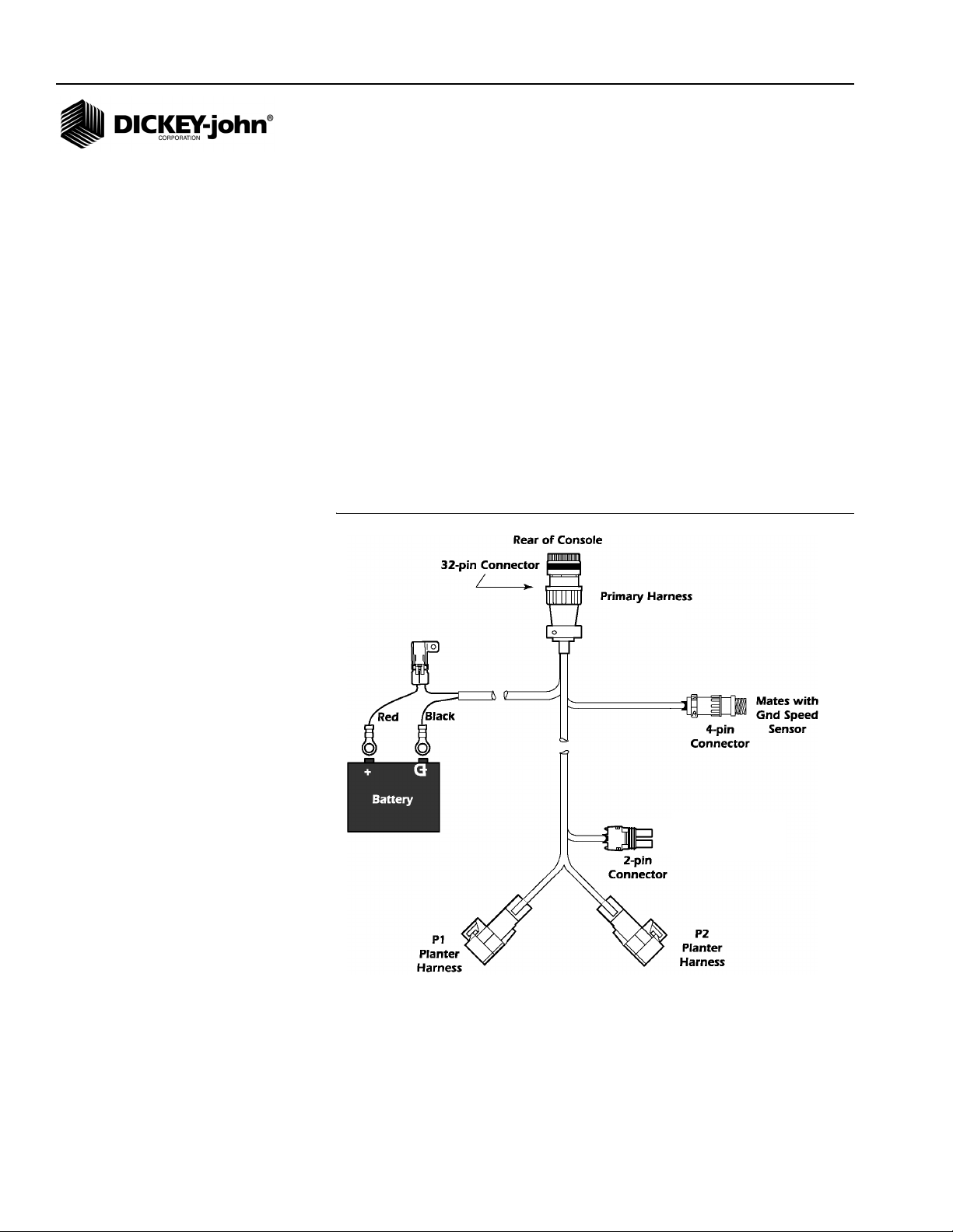
CONSOLE HARNESS INSTALLATION
The J1 connector on the back of the console connects all input and output
®
signals to the Seed Manager
shown in (Figure 3).
Harness contains connectors for
• Ground speed sensor (digital)
• Ground speed sensor (reluctance)
• System power
• P1 and P2 Bus connectors. A secondary module harness is used to
connect to P1 and/or P2.
For systems that contain a J2 connector, a separate accessory harness will
contain a RS-232 connector for PC/GPS applications.
Figure 3
Primary Tractor Harness
SE console. The primary tractor harness is
Note:
Due to the power requirements for
the Seed Manager
®
SE system,
the battery connections must be
made directly to the tractor battery.
46682-0132
Mates with Reluctance
Ground Speed Sensor
6 / INSTALLATION AND SETUP
Seed Manager SE
11001-1359A-200810
Page 9
OPERATOR’S MANUAL
Note:
Due to the power requirements for
the Seed Manager
the battery connections must be
made directly to the tractor battery.
®
SE system,
Install the primary (J1) harness from the rear of the console to the tractor
hitch as follows:
1. Route the primary harness from J1 on the console rear to the rear of
the tractor, near the hitch. Route on the side of the tractor opposite the
alternator and spark plugs.
2. Locate the harness to prevent being pinched, cut, or stepped on and
secure it with wire ties.
3. Install or connect an existing ground speed sensor. The ground speed
sensor may be one of three types – radar, reluctance, or Hall Effect. A
radar sensor or reluctance sensor connects directly to the designated
connector on the primary harness. A Hall Effect sensor may require an
adapter harness to connect to the primary harness. Sensor mounting
instructions accompany the sensor. Select the mounting location and
install as the instructions describe.
4. Refer to Implement Harness instructions on page 9 to install Module
and Sensor Harnessing.
Power connections should be made last to avoid accidental shorts
during harness installation.
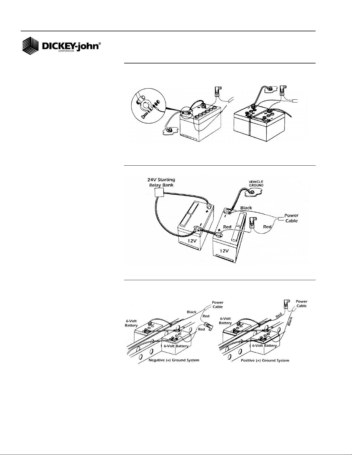
POWER CONNECTION
The Seed Manager® SE System operates on 12 volts DC only. The battery
connections on the primary harness consist of two wires, each terminated
with a ring terminal.
Before making the battery connections, determine the tractor battery
arrangement from Figures 4, 5, and 6.
After the 12 volt source is known:
1. Connect the black wire directly to the negative (-) terminal of the
battery.
2. Connect the red wire (containing the fuse link) to the positive (+)
battery terminal.
3. Ensure the connections are clean and tight. Do not route these wires
in close proximity to the existing battery cables.
4. Secure the battery wires with wire ties.
Seed Manager SE®
11001-1359A-200810
If the tractor battery arrangement differs from that shown or if any
doubt exists about how to connect to the battery, use a volt meter
first. Verify 11 to 14 volts across the battery connection points. On
tractors using two batteries, be sure to make connections to the
grounded battery.
INSTALLATION AND SETUP / 7
Page 10
OPERATOR’S MANUAL
Figure 4
12V Battery Source Connections
Vehicle
Ground
12V
Vehicle
Ground
Figure 5
24V Battery Source Connections
Red
Black
Power
Cable
6V
6V
Black
Red
Power
Cable
8 / INSTALLATION AND SETUP
Figure 6
Negative or Positive Source Connections
IMPORTANT: Before welding on the frame or chassis, be certain to
disconnect battery leads. Failure to do so could result
in damage to the Seed Manager
®
SE.
Seed Manager SE
11001-1359A-200810
Page 11

OPERATOR’S MANUAL
IMPLEMENT HARNESS/MODULE CONNECTION
The Seed Manager® SE System uses any combination of three basic
module types each with specific harness configurations.
Module Types:
• 12 Row Material Flow
• 16 Row Material Flow
•Shaft Speed
The following requirements must be observed when connecting
modules to the bus:
• A maximum of six Material Flow Modules can be connected to the bus.
• Only one Shaft Speed Module can be connected to the bus.
• The Shaft Speed Module can be connected anywhere on the bus that
is convenient and can be connected to either P1 or P2.
• A maximum of three Material Flow Modules can be connected to P1 or
P2.
• Any combination of 12 Row or 16 Row Material Flow Modules can be
used.
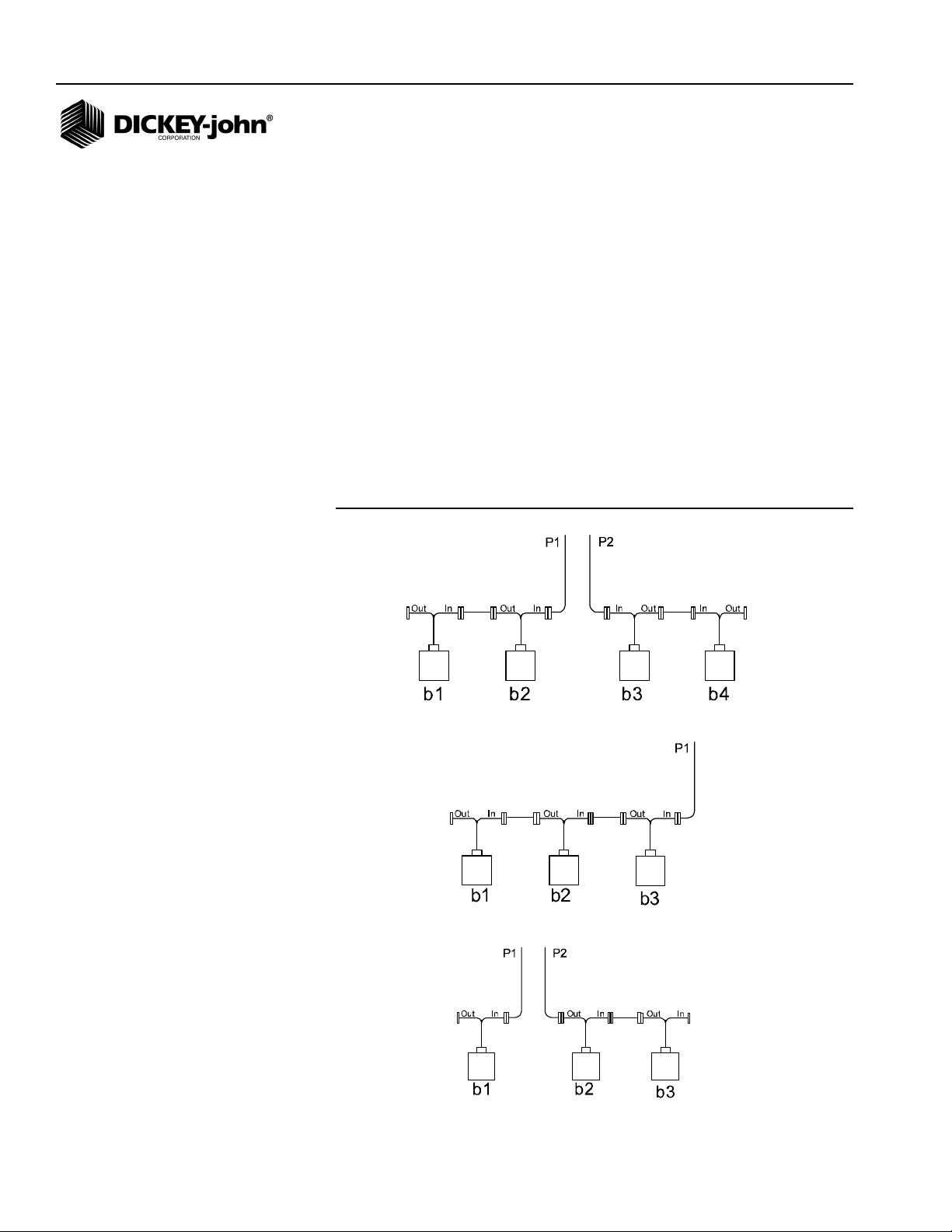
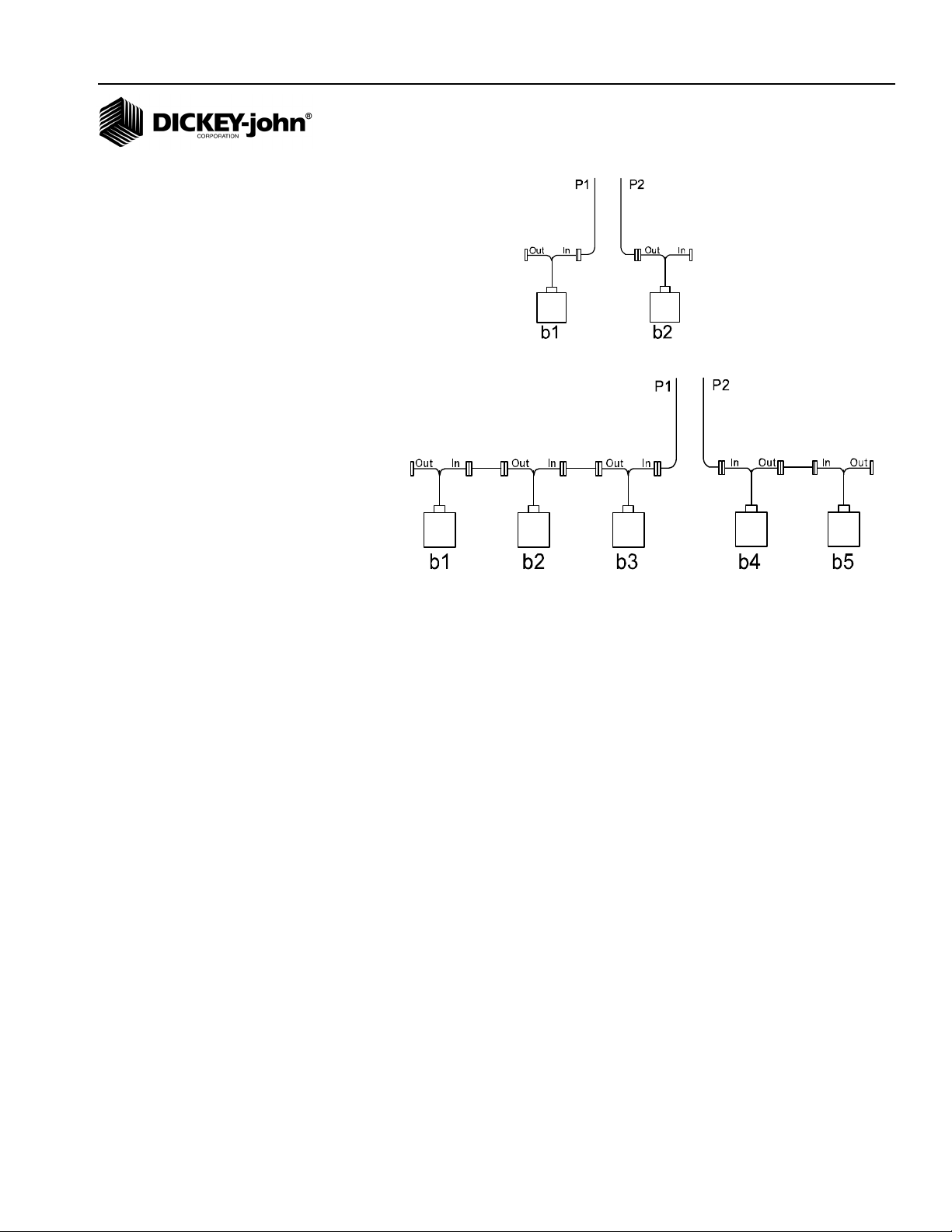
MODULE ORDER
IMPORTANT: The order in which Material Flow Modules are connected
and their position on the toolbar or implement is
important. The Material Flow Modules are identified by
the console as b1, b2, ...bn (where n is the total number
of Material Flow Modules connected). The order in
which the console identifies the modules depend on
how they are connected to the bus. Refer to (Figure 10)
that shows example system configuration setups.
A single Bus cable connects to each module then serially (daisy chains)
connects to following modules. The primary harness divides into two halves
at the implement hitch (P1 and P2).
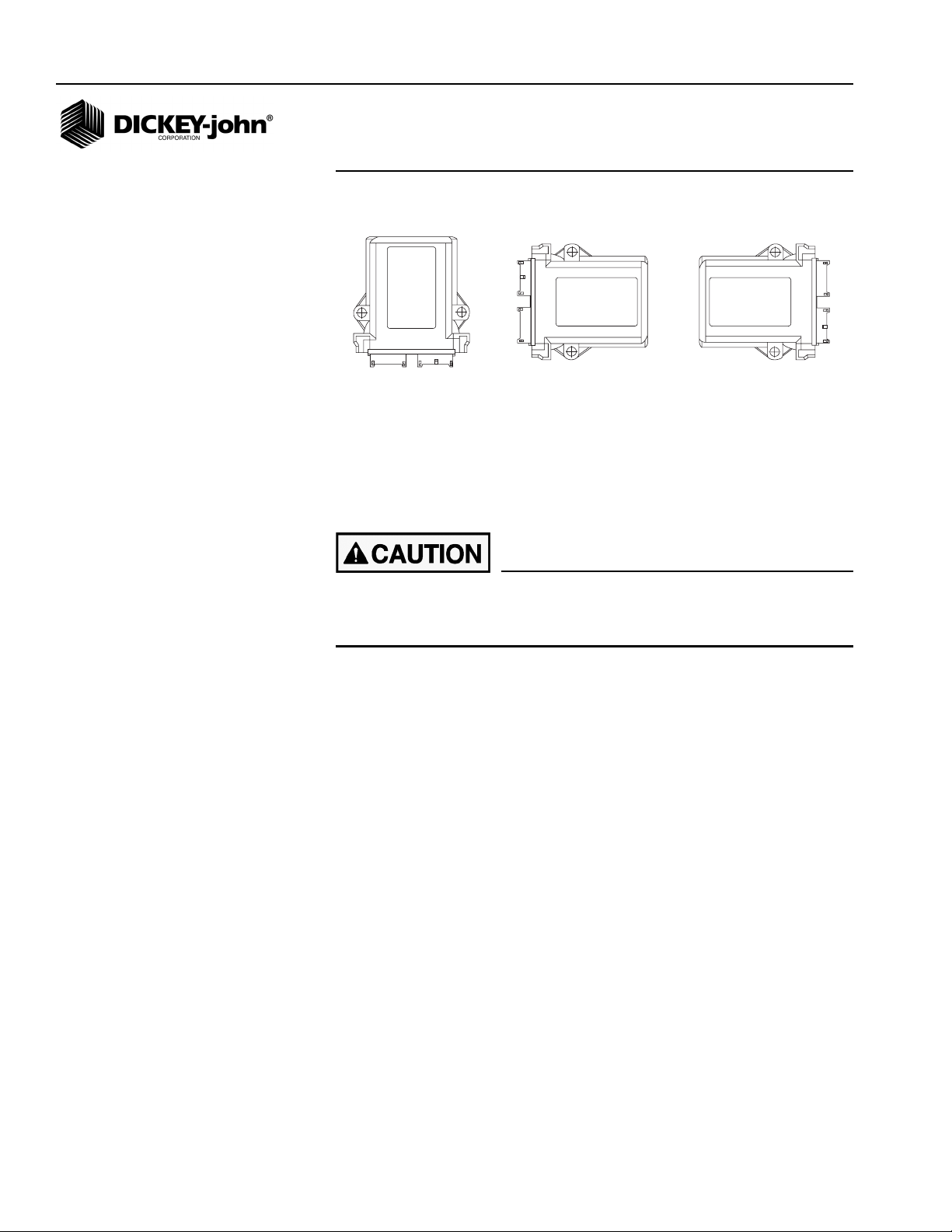
MODULE INSTALLATION
1. Select an area on the implement to mount the member that allows for
easy hookup and access. Extensions can be used to reach members
installed on remote areas of the implement.
Do not install the module in any orientation other than illustrated
in (Figure 7). The connection wires must NOT be mounted upward
as moisture can collect inside the unit and damage the circuits.
Ensure that module connectors do not face upward in a folded
position as well.
Seed Manager SE
11001-1359A-200810
INSTALLATION AND SETUP / 9
Page 12
OPERATOR’S MANUAL
Figure 7
Material Flow Module
Preferred Acceptable Acceptable
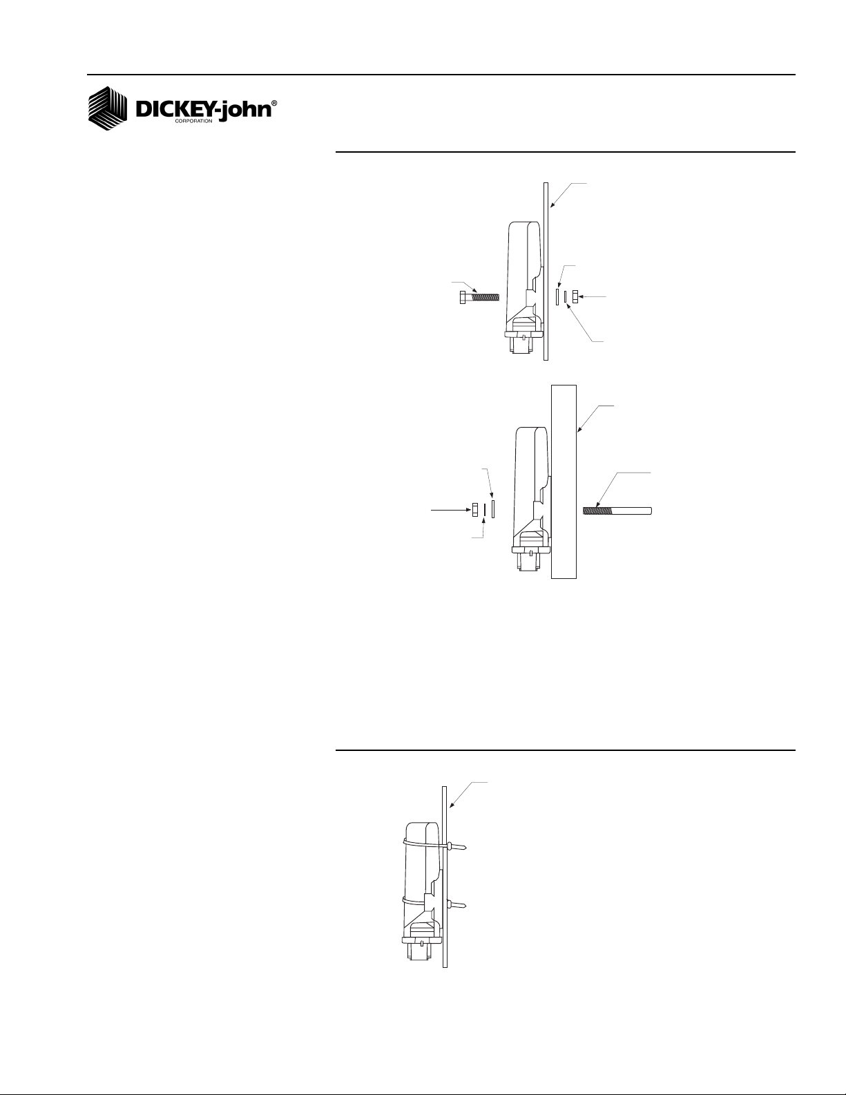
2. Mount with the label side of the module facing out.
3. To bolt the member to a frame:
• Use the enclosure as a template to mark the location of the mounting
holes.
• Drill two 9/32 inch diameter holes where marked.
• Attach to frame using 1/4 x 20 bolts or other fastening devices as
illustrated in (Figure 8).
Do not use the enclosure as a guide when drilling. Do not
overtighten nuts as this may damage the mounting tabs on the
enclosure.
10 / INSTALLATION AND SETUP
Seed Manager SE
11001-1359A-200810
Page 13
OPERATOR’S MANUAL
1/4 x 20 BOLT
1/4 F LAT WASHER
1/4 SPLIT
LOCKWASHER
1/4 N UT
IMPLEMENT
FRAME
1/4 x 20
THREADED "U"
BOLT OR
OTHER
FASTENING
DEVICE
1/4 FLAT WASHER
1/4 SPLIT LOCKWASHER
1/4 NUT
IMPLEMENT
FRAME OR
SUPPORT
IMPLEMENT
FRAME
Figure 8
Material Flow Modules (using bolts)
Seed Manager SE®
11001-1359A-200810
4. To tie strap the member to a frame:
• Use one long tie-strap to loop around the member body and through
both mounting holes as illustrated in (Figure 9).
• If necessary, drill mounting holes following the procedure described
above.
• Securely tighten tie strap.
• Install a second tie strap toward the label end of the enclosure for
additional support.
Figure 9
Material Flow Module Installation (Tie Strap)
INSTALLATION AND SETUP / 11
Page 14
OPERATOR’S MANUAL
5. Lay out each module harness along the frame of the implement to
each of the seed rows (or appropriate sensors).
6. Secure the harness to the toolbar with a minimum of 3” straight wire
exiting the module before bending and attaching with tie straps.
7. Install and/or connect each of the seed sensors (or appropriate
sensor). Sensor mounting instructions accompany the sensor. Select
the mounting location and install as described in the instructions.
8. Connect each module together with a bus harness.
IMPORTANT: Be sure the locking tabs engage when inserting the
connectors. The connection is sealed when the locking
tabs have fully engaged.
9. Connect the tractor harness P1 and P2 connectors to the bus harness.
10. Coil and secure existing cables with wire ties to avoid pinching or
damage to the harness.
MODULE SETUP EXAMPLES
Figure 10
Four Module Setup (two modules are connected to P1 and two to P2)
12 / INSTALLATION AND SETUP
Three Module Setup (All modules connected to P1)
Three Module Setup (one module connected to P1 and 2 connected to P2)
Seed Manager SE
11001-1359A-200810
Page 15
OPERATOR’S MANUAL
Two Module Setup (one module connected to both P1 and P2)
Two Module Setup (three modules connected to PA and 2 connected to P2)
As the previous examples show, b1 is always identified as the LAST module
connected to P1. The remaining modules on P1 are numbered
sequentially, along with any modules connected to P2.
Seed Manager SE
11001-1359A-200810
INSTALLATION AND SETUP / 13
Page 16
OPERATOR’S MANUAL
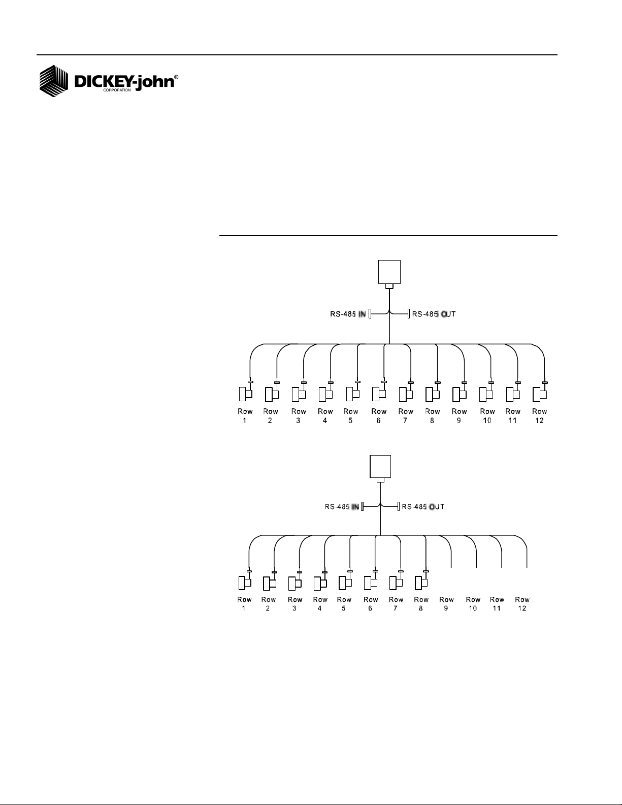
CONNECTING SENSORS TO MODULES
IMPORTANT: When connecting sensors to the Material Flow Modules,
all seed sensors installed on a Material Flow Module
must be connected sequentially starting with Row 1 as
shown below.
When correctly connected, row 1 sensor should be connected to the Row 1
input on b1. The monitor will then number the sensors from 1 to n starting
on b1, then b2, and so on.
Figure 11
Correct Install
Correct Install
14 / INSTALLATION AND SETUP
Seed Manager SE
11001-1359A-200810
Page 17
OPERATOR’S MANUAL
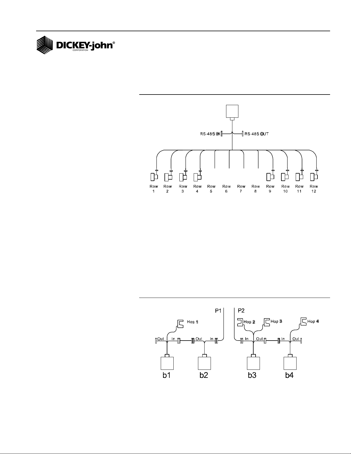
The following illustration shows eight row modules installed incorrectly.
IMPORTANT: There can be no skips in the row inputs on a Material
Flow Module.
Figure 12
Incorrect Install
HOPPER LEVEL SENSORS
Hopper level sensors can be connected to 12 Row Material Flow Modules.
Hopper sensors can be connected to either of the hopper inputs on a
Material Flow Module. The monitor will identify the number of hopper
sensors connected to each Material Flow Module and will number them
from 1 to n starting with any sensors connected to b1. If no sensors are
connected to b1, the number starts from b2 and so on.
In the event that two hopper sensors are connected to a given module, the
sensor connected to input 1 is numbered before the sensor connected to
input 2. The following shows an example configuration with hopper sensors
connected and how they would be identified by the console.
Figure 13
Hopper Sensor Connection to 12 Row Material Flow Module
Seed Manager SE
11001-1359A-200810
INSTALLATION AND SETUP / 15
Page 18
OPERATOR’S MANUAL
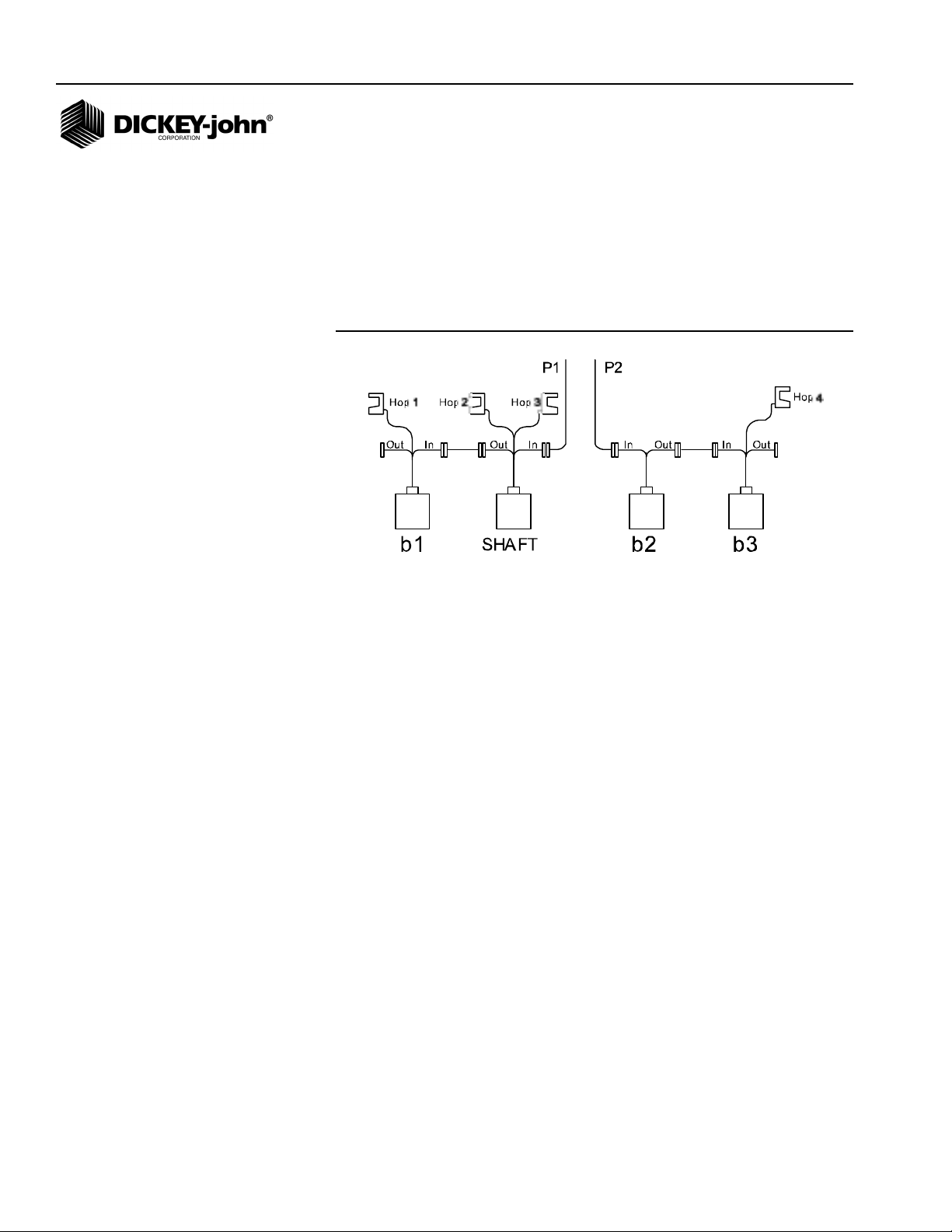
When hopper level sensors are connected to a Shaft Speed Module, they
are numbered relative to the position of the Shaft Speed Module on the bus.
If the Shaft Speed Module is connected to the RS-485 out of b1, the
numbering of the hopper sensors starts with this module, then continues
with any hopper sensors connected to b1, b2, etc. If the Shaft Speed
Module is connected between Material Flow Modules, any hopper sensors
connected are numbered in the order in which they are detected as shown
below.
Figure 14
Hopper Sensor Connection to Shaft Speed Module
16 / INSTALLATION AND SETUP
Seed Manager SE
11001-1359A-200810
Page 19
OPERATOR’S MANUAL
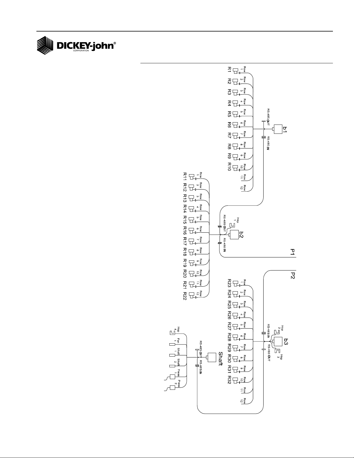
NOTE: Shaft, fan, and pressure
sensors can only be connected
to the Shaft Speed Module.
These sensors are identified by
the monitor according to what
input they are connected to
regardless of the position of the
Shaft Speed Module on the
bus. (Figure 15) shows a
complete example of a system
setup and how each connected
sensor would be identified.
Figure 15
Seed Manager SE
11001-1359A-200810
INSTALLATION AND SETUP / 17
Page 20
OPERATOR’S MANUAL
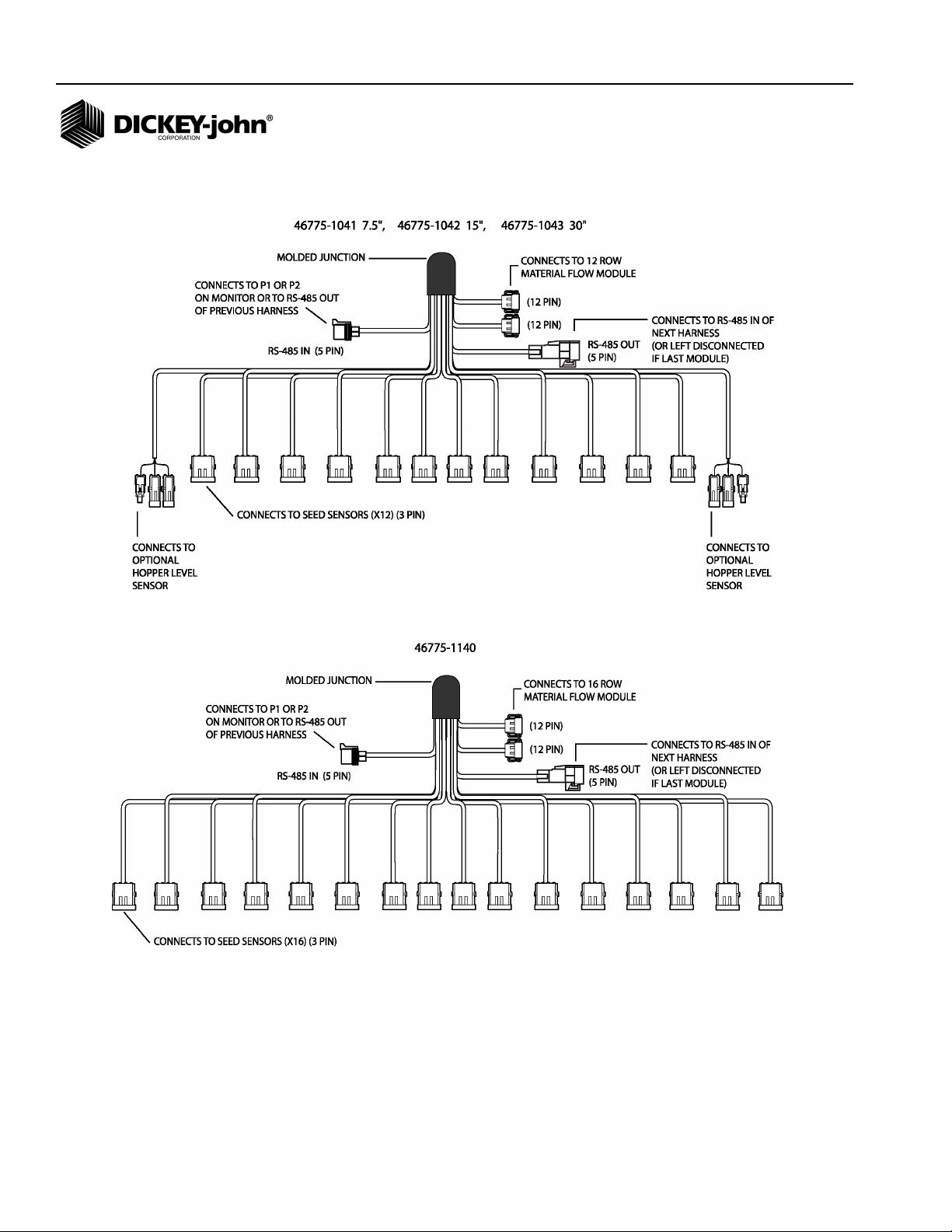
HARNESSES
12 ROW HARNESS
16 ROW HARNESS
18 / INSTALLATION AND SETUP
Seed Manager SE
11001-1359A-200810
Page 21
OPERATOR’S MANUAL
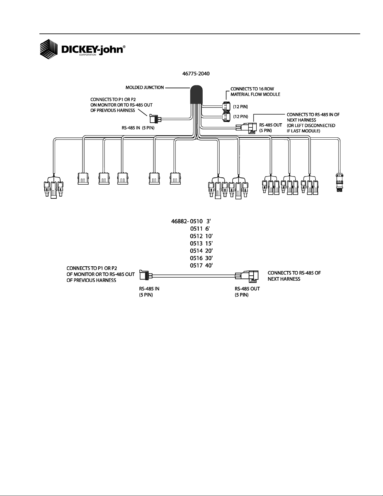
SHAFT SPEED MODULE HARNESS
RS485 EXTENSION HARNESS
Seed Manager SE®
11001-1359A-200810
INSTALLATION AND SETUP / 19
Page 22

OPERATOR’S MANUAL
20 / INSTALLATION AND SETUP
Seed Manager SE
11001-1359A-200810
Page 23

OPERATOR’S MANUAL
STARTUP
SWITCHPAD OVERVIEW
The control pad buttons on the switchpad are used to control system power,
select the mode of operation, and enter implement configuration constants.
An overview of the switches follows:
ON OFF
Pressing this switch applies power to the monitor. Upon power up, the
monitor performs internal diagnostic checks, illuminates all segments of the
LCD, sounds the alarm, and determines what sensors are connected to the
system. Pressing the ON OFF switch for at least one (1) second causes the
system to power down.
1 2 3 . . .
ALARM
Momentarily pressing this switch silences the alarm and acknowledges the
alarm condition. Additionally, holding the switch pressed for more than one
(1) second allows the volume level of the alarm to be adjusted. As the
switch is pressed, the alarm sounds continuously and the volume level
slowly decreases to a minimum, then increases to a maximum. Releasing
the switch establishes the desired volume level.
SETUP
Press for one (1) second to enter the Setup Mode and to step from one
Setup constant to the next as detailed in the Setup Mode section.
MIN AVG MAX SCAN
Press to toggle between the MIN AVG MAX and SCAN options for
Population and Spacing.
SELECT ROW
Pressing this switch while in Population or Spacing functions freezes the
display on the current row data. Successive depressions then cause
stepping from one row to the next. In the Setup Mode, this switch allows
stepping through the rows while entering Row Status.
Seed Manager SE
11001-1359A-200810
STARTUP / 21
Page 24

OPERATOR’S MANUAL
SELECT
SET
START
STOP
RESET
SELECT
The Select button changes constants in the Setup Mode as explained in the
Setup Mode section. To move the selected digit to the next digit, press the
SELECT switch.
SET
The Set button changes constants in the Setup Mode as explained in the
Setup Mode section. To increase the selected digit by one, press the SET
switch. SET can also toggle a selection between ON and OFF for example.
START STOP RESET
This switch is used in multiple modes for multiple purposes. Some
examples are as follows. Used in the Operate Mode Seed Count and
Distance Accumulator functions to start or stop the accumulations. It is also
used in Setup Mode Distance Calibration, Automatic Configuration, and
Sensor Self Test functions to start or stop the test. Other functions include
Clearing the Run Hours, Area Accumulators, Seed Count, Distance
Accumulator, and simply clearing digits when editing Setup constant
values.
l l l l
BACK
This switch is used in multiple modes for several purposes. Some
examples are as follows. Used in the Operate Mode Population and
Spacing functions to step to the previous row display. It is also used in
Setup Mode to return to the previous Setup Mode screen.
OPERATE 1
This switch is used to select Population, Spacing, or Ground Speed Mode.
Successive presses of the switch will change to the next mode.
22 / STARTUP
Seed Manager SE
11001-1359A-200810
Page 25

OPERATOR’S MANUAL
OPERATE 2
Selects Fan Speed, Shaft Speed, or Pressure Mode (if available on
system). Successive presses of the switch will change to the next mode.
OPERATE 3
1 2 3 ...
1 2 3 4 5
Selects Area, Seed Count, or Distance Accumulator Mode. Successive
presses of the switch will change to the next mode.
Seed Manager SE®
11001-1359A-200810
STARTUP / 23
Page 26

OPERATOR’S MANUAL
SETUP MODE
SETUP CONSTANTS
The Setup Mode is used to enter the implement configuration constants
which are listed in (Figure 16), in the order of their presentation.
Pressing the Setup switch for one (1) second places the console in the
Setup Mode which is identified by the SETUP message on the display.
Additional messages uniquely identify the constant displayed and available
for editing at any given time.
Each constant has a fixed number of digits. Leading zeroes will display. To
change the value of a constant, use the SELECT, SET, and START STOP
RESET switches as follows:
• Initially the left most digit flashes on and off indicating it is the “selected
digit”.
• Pressing the SET switch increases the selected digit by one count.
After reaching the maximum value of nine (9), the digit rolls over to
zero (0).
• Press the START STOP RESET to set the digits to zero.
• Pressing the SELECT switch makes the next digit to the right the
selected digit.
• When the desired value is entered (or there is no change from the
original value), press the Setup switch to store the value and advance
to the next constant on the list.
• To return to the previous constant on the list, press the BACK switch. If
a value is entered which exceeds the minimum or maximum shown for
that constant in (Figure 16), the alarm sounds for one (1) second, the
value of the exceeded limit appears on the screen, and the advance to
the next constant is aborted.
NOTE: To allow rapid recovery from an
entry error, it is important to
record all values of constants
on the SETUP RECORD sheet
on the last page of this manual
immediately after console entry.
24 / STARTUP
Seed Manager SE
11001-1359A-200810
Page 27

OPERATOR’S MANUAL
IMPORTANT:
If the Number of Seed Modules,
Number of Fan Speed Sensors,
Number of Shaft Speed
Sensors, or Number of Pressure
Sensors is set to “0” or another
value below the maximum, the
appropriate subcategory
screens will not display.
Figure 16
Setup Mode Parameters
Order Setup Mode Default Minimum Maximum
1 Seed Flow 00 00 10
2 Population Hi Limit 0034.0 0000.0 9999.9
3 Population Lo Limit 0026.0 0000.0 9999.9
4 Row Width 030.0 001.0 999.9
5 Implement Width N/A 0001.0 9999.9
6 Ground Speed Source d1 N/A N/A
7 Distance Calibration 6096 250 9999
8 Automatic Configuration N/A N/A N/A
9 Split Row Configuration 00 00 20
10 Number of Seed Modules 1 1 6
10A Number of Seed Sensors Module 1 01 01 16
10B Number of Seed Sensors Module 2 01 01 16
10C Number of Seed Sensors Module 3 01 01 16
10D Number of Seed Sensors Module 4 01 01 16
10E Number of Seed Sensors Module 5 01 01 16
10F Number of Seed Sensors Module 6 01 01 16
11 Row Status ON N/A N/A
12 Total Number of Rows Configured N/A 01 96
13 Number of Fan Speed Sensors 0 0 2
13A Fan Speed Sensor 1 Constant 000.0 000.0 999.99
13B Fan Speed Sensor 1 Hi Limit 00065 00000 99999
13C Fan Speed Sensor 1 Lo Limit 00045 00000 99999
13D Fan Speed Sensor 2 Constant 000.0 000.00 999.99
13E Fan Speed Sensor 2 Hi Limit 00065 00000 99999
13F Fan Speed Sensor 2 Lo Limit 00045 00000 99999
14 Number of Shaft Speed Sensors 0 0 3
14A Shaft Speed Sensor 1 Constant 000.00 000.00 999.99
14B Shaft Speed Sensor 1 Hi Limit 00065 00000 99999
14C Shaft Speed Sensor 1 Lo Limit 00045 00000 99999
14D Shaft Speed Sensor 2 Constant 000.00 000.00 999.99
14E Shaft Speed Sensor 2 Hi Limit 00065 00000 99999
14F Shaft Speed Sensor 2 Lo Limit 00045 00000 99999
14G Shaft Speed Sensor 3 Constant 000.00 000.00 999.99
14H Shaft Speed Sensor 3 Hi Limit 00065 00000 99999
14I Shaft Speed Sensor 3 Lo Limit 00045 00000 99999
15 Number of Hopper Sensors 0 0 7
16 Number of Pressure Sensors 0 0 2
16A Pressure Sensor 1 Hi Limit 000.0 000.0 999.9
16B Pressure Sensor 1 Lo Limit 000.0 000.0 999.9
16C Pressure Sensor 2 Hi Limit 000.0 000.0 999.9
16D Pressure Sensor 2 Lo Limit 000.0 000.0 999.9
17 Blockage Mode Configuration 0 0 2
18 Population Filter 00 00 99
19 Population Scalar 100 001 999
20 Sensor/Module Self-Test N/A N/A N/A
21 English/Metric Units English N/A N/A
Seed Manager SE
11001-1359A-200810
To exit the Setup Mode, press any of the three Operate switches. Exiting
automatically stores the last constant changed.
STARTUP / 25
Page 28

OPERATOR’S MANUAL
Definitions and considerations when entering values for each constant are
as follows:
NOTE: Use (Figure 16) Setup Mode
Parameters as reference for the
following items numbered 1-21.
1. SEED FLOW ALARM ADJUSTMENT
The first parameter displayed after entering the Setup Mode is Seed Flow
Alarm Adjustment identified as “SF” on the top of the display. The Seed
Flow Alarm Adjustment establishes how many seeds per time interval must
flow past the sensor before the alarm is activated identifying a row failure.
The default value is 00 which requires a minimum seed flow of at least 2
seeds per second before row failure alarm activates. The maximum value
allowed is at least 1 seed every 10 seconds. (Figure 17) indicates a
minimum of 1 seed every 4 seconds before row failure alarm will sound.
Below Seed Flow Alarm Values table lists the values and the relative time
intervals. Any number higher than 10 will default to the maximum value of
10.
Figure 17
Seed Flow Alarm Adjustment Display
26 / STARTUP
Seed Flow Alarm Values
00 2 seeds per second (default)
01 1 seed per second
02 1 seed every 2 seconds
03 1 seed every 3 seconds
04 1 seed every 4 seconds
05 1 seed every 5 seconds
06 1 seed every 6 seconds
07 1 seed every 7 seconds
08 1 seed every 8 seconds
09 1 seed every 9 seconds
10 1 seed every 10 seconds
Seed Manager SE
11001-1359A-200810
Page 29

OPERATOR’S MANUAL
2. POPULATION HI LIMIT
When the population on any row exceeds the value entered for this
constant, in thousands of seeds per acre (hectare), the alarm sounds as
indicated under the heading ALARMS, POPULATION HI LIMIT WARNING.
(Figure 18) shows the display for a limit of 176,000 seeds/acre.
Figure 18
Population Hi Limit Display
3. POPULATION LO LIMIT
When the population on any row falls below the value entered for this
constant, in thousands of seeds per acre (hectare), the alarm sounds, as
indicated under the heading ALARMS, POPULATION LO LIMIT
WARNING. (Figure 19) shows the display for a limit of 144,500 seeds/acre.
Figure 19
Population Lo Limit Display
4. ROW WIDTH
This is the distance in inches (centimeters) between rows with a resolution
of 0.1. (Figure 20) shows a row width of 38.0 inches.
Figure 20
Row Width Display
Seed Manager SE
11001-1359A-200810
STARTUP / 27
Page 30

OPERATOR’S MANUAL
5. IMPLEMENT WIDTH
This is the seeding width of the implement in inches (centimeters) with a
resolution of 0.1. It is automatically calculated when either the Number of
Modules, Number of Rows per Module, or the Row Width is changed and
can be edited for special applications such as skip row seeding. (Figure 21)
shows an implement width of 720.0 inches.
NOTE: Use (Figure 16) Setup Mode
Parameters as reference for the
following items numbered 1-21.
Figure 21
Implement Width
6. GROUND SPEED SOURCE
Pressing the Set switch causes the lower right display to toggle between
“d1”, “r1”, or “d2”. If a digital (radar or Hall Effect) type ground speed sensor
®
is used and is connected directly to the Seed Manager
SET switch until “d1” appears.
If a digital (radar or Hall Effect) type ground speed sensor is used and is
connected to a Shaft Speed Module, press the SET switch until “d2”
appears. If a reluctance type ground speed sensor is used, press the SET
switch until “r1” appears. (Figure 22) shows a configuration for a digital 1
ground speed source.
Console, press the
28 / STARTUP
Figure 22
Ground Speed Sensor Type Display
7. DISTANCE CALIBRATION
The Distance Calibration constant is the number of pulses generated by the
ground speed sensor while traveling a distance of 400 feet (122 meters).
(Figure 23) shows the display with the SETUP, SPEED, and COUNT
messages and the default value of 6096 which is the nominal pulse count
for the radar ground speed sensor. A smaller number, typically 3100,
results with a reluctance ground speed sensor.
Seed Manager SE
11001-1359A-200810
Page 31

OPERATOR’S MANUAL
Figure 23
Distance Calibration Display
To Perform the Distance Calibration:
1. Carefully measure a 400 foot (122 meter) course plainly marking the
start and finish points.
2. With the tractor moving between 2 and 5 MPH (3.2 and 8 Km/h), press
the START STOP RESET switch when the tractor is exactly even with
the start marker. The display showing the Distance Calibration
Constant zeroes, then counts the ground speed pulses.
3. When even with the finish marker, press the START STOP RESET
switch.
4. To ensure best accuracy, perform this procedure at least three (3)
times. Record the count each time, then enter the average as the
Distance Calibration Constant, using the SELECT and SET switches.
8. AUTOMATIC CONFIGURATION
To Begin the Automatic Configuration:
1. Press the START STOP RESET switch. The TEST message flashes
while the Automatic Configuration is running.
2. Configuration is complete when the TEST message disappears.
3. The Automatic Configuration will automatically detect how many seed
modules, seed sensors, hopper sensors, and pressure sensors are
connected in the system.
IMPORTANT: Fan Speed Sensors and Shaft Speed Sensors are not
automatically configured and will need to be setup
manually.
4. Verify the detected configuration by reviewing the setup constants for
the number of seed modules, seed sensors, hopper sensors, and
pressure sensors before beginning implement operation. (Figure 24)
shows the Automatic Configuration screen.
Seed Manager SE
11001-1359A-200810
STARTUP / 29
Page 32

OPERATOR’S MANUAL
Figure 24
Automatic Configuration Display
9. SPLIT ROW CONFIGURATION
For split, twin, or skip row type seeding implements, this feature allows easy
configuration for setting up the correct row pattern that is used. Reference
(Figure 25) for a listing of all of the row patterns that can be applied to the
system. When a row pattern is selected all of the rows are automatically
turned ON or OFF according to the pattern. Individual rows can be edited in
the Row Configuration Screen, but that must be done after a pattern is
selected. (Figure 26) shows a row pattern of 01 being selected.
Figure 25
Split Row Configuration
Split Row
Configuration Description/Example
00 A ll Row s On
01 Every other row OFF w ith f irs t row ON (OXOXOX)
02 Every other row OFF w ith f irs t row OFF ( XOXOXO)
03 Every 3rd row ON (OXXOXXOXX)
04 Every 3rd row ON (XXOXXOXXO)
05 Every 3rd row ON (XOXXOXXOXX)
06 Every 3rd row OFF (OOXOOXOOX)
07 Every 3rd row OFF (OXOOXOOXOO)
08 Ever y 3 r d row OFF (XOOXOOXOO)
09 Ever y 4th r ow ON (OXXXOXXXOXXX)
10 Every 4th row ON (XXXOXXXOXXXO)
11 Every 4th r ow ON (XXOXXXOXXXOXXX)
12 Every 4th row ON (XOXXXOXXXOXXX)
13 Tw in row s (OOXXOOXXOOXX)
14 Tw in Rrow s (OXXOOXXOOXXOO)
15 Tw in Row s ( XXOOXXOOXXOO)
16 Tw in Row s (XOOXXOOXXOOXX)
17 Ever y 4 th r ow OFF (OOOXOOOXOOOX)
18 Ever y 4 th r ow OFF (OOXOOOXOOOXOOO)
19 Ever y 4 th r ow OFF (OXOOOXOOOXOOO)
20 Ever y 4 th r ow OFF (XOOOXOOOXOOO)
30 / STARTUP
Seed Manager SE
11001-1359A-200810
Page 33

OPERATOR’S MANUAL
Figure 26
Pattern Select Display
NOTE: Use (Figure 16) Setup Mode
Parameters as reference for the
following items numbered 1-21
10. NUMBER OF SEED MODULES
This is the actual number of seed modules that are connected to the
system. Note: This does not include the shaft speed module if one is
available on the system. This parameter will be checked as part of the
Sensor/Module Self-Test and error codes generated if this value does not
match the actual number of seed modules. (Figure 27) shows a
configuration for six (6) modules.
Figure 27
Seed Modules Display
10A-E. Number of Seed Sensors Per Module
For each seed module that is configured on the previous Setup screen,
there will be a Number of Seed Sensors per Module screen. This is the
actual number of seed sensors that are connected to the particular module.
The modules are numbered from the far left of the implement (end of P1) to
the far right of the implement (end of P2). This parameter will be checked
as part of the Sensor/Module Self-Test and error codes will be generated if
this value does not match the actual number of seed sensors. (Figure 28)
shows twelve (12) seed sensors configured on module 3.
Seed Manager SE
11001-1359A-200810
STARTUP / 31
Page 34

OPERATOR’S MANUAL
Figure 28
Sensors Per Module Display
11. ROW STATUS
This parameter allows placing individual seed sensors in ON or OFF status.
For those situations where it is necessary to turn off certain rows on the
implement, OFF status turns off the related sensors so alarms do not occur.
The display initially shows the messages SETUP, ROW 1, and the status of
row 1. (Figure 29) shows row 7 status set to OFF. Press the SET switch to
toggle between ON and OFF for standard and Hi-Rate seed sensors. Press
the SELECT ROW switch to advance to the next row. When the status of
all rows is correctly entered, press SETUP to advance to the next Setup
constant.
Figure 29
Row Status Display
32 / STARTUP
Seed Manager SE
11001-1359A-200810
Page 35

OPERATOR’S MANUAL
12. TOTAL NUMBER OF ROWS CONFIGURED
This parameter is used to calculate implement width and is used in
checking the number of seed sensors detected upon system power up.
This value is displayed for confirmation only and can only be altered by
changing the Number of Seed Modules or Number of Seed Sensors per
Module parameters. (Figure 30) shows the display for sixteen (16) rows.
NOTE: Use (Figure 16) Setup Mode
Parameters as reference for the
following items numbered 1-21
Figure 30
Rows Configured Display
13. NUMBER OF FAN SPEED SENSORS
This is the actual number of fan speed sensors that are connected to a shaft
speed module on the system. For each fan speed sensor that is
configured, there will be an operate screen generated. Fan speed sensors
are not self tested and will not generate any error codes except for
operational error codes for hi and lo limit warnings. (Figure 31) shows a
configuration of two (2) fan speed sensors.
Figure 31
Fan Speed Sensor Display
Seed Manager SE
11001-1359A-200810
STARTUP / 33
Page 36

OPERATOR’S MANUAL
13A and 13D. Fan Speed Sensor Constant
The Fan Speed Constant is the number of pulses the fan speed sensor
generates in one revolution of the monitored fan. This is typically the
number of teeth (sense points) on the fan. The fan speed constant can be
entered as a decimal with 0.01 resolution. Entering a value of zero (000.00)
disables the fan speed function. The Fan Speed Sensor Constant is
accessible only if the Number of Fan Speed Sensors has a value other than
0. (Figure 32) shows the display with a Fan Speed Constant of 34.00
pulses per revolution.
Figure 32
Fan Speed Constant Display
13B and 13E. Fan Speed Sensor Hi Limit
This constant is the highest fan speed (RPM) allowed before sounding a
warning alarm. The hi and lo warning limits are accessible only if the
Number of Fan Speed Sensors has a value other than 0. The warning is
enabled or disabled by selecting the ON or OFF message. Use the
SELECT switch to advance one step to the right of the right most digit, then
press the SET switch to toggle between ON and OFF. (Figure 33) shows a
limit of 500 RPM with the warning enabled.
Figure 33
Hi Limit Fan Speed Display
34 / STARTUP
Seed Manager SE
11001-1359A-200810
Page 37

OPERATOR’S MANUAL
13C and 13F. Fan Speed Sensor Lo Limit
This constant is the lowest fan speed (RPM) allowed before sounding a
warning alarm. The hi and lo warning limits are accessible only if the
Number of Fan Speed Sensors has a value other than 0. The warning is
enabled or disabled by selecting the ON or OFF message. Use the
SELECT switch to advance one step to the right of the right most digit, then
press the SET switch to toggle between ON and OFF. (Figure 34) shows a
limit of 25 RPM with the warning disabled.
NOTE: Use (Figure 16) Setup Mode
Parameters as reference for the
following items numbered 1-21
Figure 34
Lo Limit Fan Speed Display
14. NUMBER OF SHAFT SPEED SENSORS
This is the actual number of shaft speed sensors that are connected to a
shaft speed module on the system. For each shaft speed sensor that is
configured there will be an operate screen generated. Shaft speed sensors
are not self tested and will not generate any error codes except for
operational error codes for Hi and Lo Limit warnings. (Figure 35) shows a
configuration of three (3) shaft speed sensors.
Figure 35
Shaft Speed Sensor Display
Seed Manager SE
11001-1359A-200810
STARTUP / 35
Page 38

OPERATOR’S MANUAL
14A, 14D, and 14G. Shaft Speed Sensor Constant
The Shaft Speed Constant is the number of pulses the shaft speed sensor
generates in one revolution of the monitored shaft. This is typically the
number of teeth (sense points) on the gear attached to the monitored shaft.
The Shaft Speed Constant can be entered as a decimal with 0.01
resolution. Entering a value of zero (000.00) disables the shaft speed
function. The Shaft Speed Sensor Constant is accessible only if the
Number of Shaft Speed Sensors has a value other than 0. (Figure 36)
shows the display with a Shaft Speed Constant of 26.00 pulses per
revolution.
Figure 36
Shaft Speed Constant Display
14B, 14E, and 14H. Shaft Speed Sensor Hi Limit
This constant is the highest shaft speed (RPM) allowed before sounding a
warning alarm. The hi and lo warning limits are accessible only if the
Number of Shaft Speed Sensors has a value other than 0. The warning is
enabled or disabled by selecting the ON or OFF message. Use the
SELECT switch to advance one step to the right of the right most digit, then
press the SET switch to toggle between ON and OFF. (Figure 37) shows a
limit of 65 RPM with the warning enabled.
Figure 37
Hi Limit Shaft Speed Display
36 / STARTUP
Seed Manager SE
11001-1359A-200810
Page 39

OPERATOR’S MANUAL
14C, 14F, and 14I. Shaft Speed Sensor Lo Limit
This constant is the lowest shaft speed (RPM) allowed before sounding a
warning alarm. The hi and lo warning limits are accessible only if the
Number of Shaft Speed Sensors has a value other than 0. The warning is
enabled or disabled by selecting the ON or OFF message. Use the
SELECT switch to advance one step to the right of the right most digit, then
press the SET switch to toggle between ON and OFF. (Figure 38) shows a
limit of 12 RPM with the warning disabled.
NOTE: Use (Figure 16) Setup Mode
Parameters as reference for the
following items numbered 1-21.
Figure 38
Low Limit Shaft Speed Display
15. NUMBER OF HOPPER LEVEL SENSORS
This is the actual number of hopper level sensors that are connected to all
modules in the system. This parameter will be checked as part of the
sensor/module self test and error codes will be generated if this value does
not match the actual number of hopper level sensors. (Figure 39) shows a
configuration of five (5) hopper sensors.
Figure 39
Hopper Level Display
Seed Manager SE
11001-1359A-200810
STARTUP / 37
Page 40

OPERATOR’S MANUAL
16. NUMBER OF PRESSURE SENSORS
This is the actual number of pressure sensors that are connected to a shaft
speed module on the system. This parameter will be checked as part of the
Sensor/Module Self-Test and error codes will be generated if this value
does not match the actual number of pressure sensors. (Figure 40) shows
a configuration of one (1) pressure sensor.
Figure 40
Pressure Sensor Display
16A and 16C. Pressure Sensor Hi Limit
2
The Pressure Sensor Hi Limit Warning is entered in oz/in
and lo warning limits are accessible only if the Number of Pressure Sensors
has a value other than 0. Setting the Pressure Sensor Hi Limit will cause
the audible alarm to sound when the pressure exceeds the value that has
been entered. Use the SET and SELECT switches to adjust the Pressure
Sensor Hi Limit value. The Pressure Sensor Hi Limit can be enabled or
disabled by selecting the ON or OFF symbol after the rightmost digit.
Pressing the SET switch will toggle the status of the warning between ON
and OFF. (Figure 41) shows a Pressure Sensor Hi Limit of 18.0 with the
warning enabled.
Figure 41
Hi Limit Pressure Display
(kPa). The hi
38 / STARTUP
Seed Manager SE
11001-1359A-200810
Page 41

OPERATOR’S MANUAL
16B and 16D. Pressure Sensor Lo Limit
NOTE: Use (Figure 16) Setup Mode
Parameters as reference for the
following items numbered 1-21
The Pressure Sensor Lo Limit Warning is entered in oz/in
2
(kPa). The hi
and lo warning limits are accessible only if the Number of Pressure Sensors
has a value other than 0. Setting the Pressure Sensor Lo Limit will cause
the audible alarm to sound when the pressure falls below the value that has
been entered. Use the SET and SELECT switches to adjust the Pressure
Sensor Lo Limit value. The Pressure Sensor Lo Limit can be enabled or
disabled by selecting the ON or OFF symbol after the rightmost digit.
Pressing the SET switch will toggle the status of the warning between ON
and OFF. (Figure 42) shows a Pressure Sensor Lo Limit of 3.8 with the
warning disabled.
Figure 42
Lo Limit Pressure Display
17. BLOCKAGE MODE CONFIGURATION
This configuration will select one of three different modes according to the
Table in (Figure 43). If Mode 0 or Mode 1 is selected, the Operate screens
will cycle through the Population Rows only. If Mode 2 is selected, the
Population and Spacing Operate screens will show a series of 5 dashes to
represent no data. In all modes, row failures will display according to the
details in the ALARMS section of this document. (Figure 44) shows a
Blockage Mode Configuration of 0.
Figure 43
Blockage Configuration
Blockage
Mode Description
0 All Rows are configured for displaying Population
First Row of each Module is configured for displaying Population-
1
All other rows are configured for Blockage Only
2 All Rows are configured for Blockage Only
Seed Manager SE
11001-1359A-200810
STARTUP / 39
Page 42

OPERATOR’S MANUAL
Figure 44
Blockage Mode Display
18. POPULATION FILTER
In certain applications the Seed Manager® SE, due to its rapid update rate,
might exhibit fluctuations in population and spacing that are undesirable.
The population filtering option applies an averaging filter to the population
and spacing calculations. The filter values range from 0 to 99, with 0 having
no filtering effect, and 99 being the maximum filtering value. Use the SET
and SELECT switches to adjust the filtering value. (Figure 45) shows a
population filter of 15.
Figure 45
Population Filter Display
40 / STARTUP
Seed Manager SE
11001-1359A-200810
Page 43

OPERATOR’S MANUAL
19. POPULATION SCALING FACTOR
The population scaling factor allows fine adjustments to be made in the
readout of population and spacing on a percentage basis. This value is
adjustable from 1% to 999% with the factory default being 100%. Use the
SET and SELECT switches to adjust to the desired population scaling
factor. (Figure 46) shows a Population Scalar of 105%.
NOTE: Use (Figure 16) Setup Mode
Parameters as reference for the
following items numbered 1-21
NOTE: For a full description of all the
error codes and their meanings,
see the ERROR CODES
section.
Figure 46
Population Scaling Display
20. SENSOR/MODULE SELF-TEST
Start the test by pressing the START STOP RESET switch. The TEST
message flashes while the test is executing (Note: This is the same test
that is performed automatically during console power up). When the test is
complete the display will show either PASSED (and scroll through all
available seed rows) or show FAILED and display the appropriate error
code(s). If multiple errors exist, the E in the error code will be flashing. To
view the next error code, press the Alarm switch. (Figure 47) shows the
Sensor/Module Self Test screen.
Figure 47
Sensor Self Test Display
Seed Manager SE
11001-1359A-200810
STARTUP / 41
Page 44

OPERATOR’S MANUAL
21. ENGLISH/METRIC UNITS
Selects the system of units with this constant. The SET switch is used to
toggle between English and Metric units. (Figure 48) shows the display
when Metric units are selected. The METRIC message is absent when
English units are selected.
Figure 48
Units Selection Display
CUSTOMER SETUP CONSTANTS
The Customer Setup Constants are entered by holding the SETUP switch
depressed while powering on the console and continuing to press until the
Display Test begins. A flashing SETUP message indicates the console is in
the Customer Setup Constants. Press the SETUP switch to advance to the
next Customer Setup Constant. To exit the Customer Setup Constants,
power off the console. The different Customer Setup Constants are listed
as follows:
Figure 49
Boot Number Display
Boot Version Number
DICKEY-john’s Service Department may request the customer to observe
and record the four (4) different 4-digit numbers (to identify the “boot
memory” software version) in the unlikely event field problems occur.
The first 4-digit number shows on the upper numeric display at the same
time a “b1” identifier appears on the lower numeric display. Record this
number, then press and release the SELECT switch to step to the “b2”,
“b3”, and “bc” numbers, recording each 4-digit number along with its
identifier. To return to “b1” again press the SELECT switch. Press SETUP
to advance to the next constant. (Figure 49) shows “0197” for “b1”, the first
Boot Version Number.
42 / STARTUP
Seed Manager SE
11001-1359A-200810
Page 45

OPERATOR’S MANUAL
Flash Version Number
DICKEY-john’s Service Department may require the four (4) different 4-digit
numbers (to identify the “flash memory” software version) if a field problem
occurs.
The first 4-digit number shows on the upper numeric display at the same
time an “F1” identifier appears on the lower numeric display. Record this
number, then press and release the SELECT switch to step to the “F2”,
“F3”, and “Fc” numbers, recording each 4-digit number along with its
identifier. To return to “F1” again press the SELECT switch. Press SETUP
to advance to the next constant. (Figure 50) shows “12bE” for “Fc”, the first
Boot Version Number.
Figure 50
Flash Version Number Display
Seed Manager SE
11001-1359A-200810
STARTUP / 43
Page 46

OPERATOR’S MANUAL
44 / STARTUP
Seed Manager SE
11001-1359A-200810
Page 47

OPERATOR’S MANUAL
OPERATION
OPERATE MODE
Performance of the following Operate Mode functions assumes the console
has been properly installed and setup as detailed in the INSTALLATION
and SETUP MODE sections respectively. (Figure 51) lists all Operate
Mode functions and shows which are available in Speed Area Mode
(defined later in this section). This list includes all the function names on
the three (3) Operate Mode switches, plus the Run Hours function which is
performed automatically.
Figure 51
Operate Mode Function Name Available in Speed Area Mode
Run Hours
Population
Seed Spacing
Ground Speed
Fan Speed
Shaft Speed
Pressure
Area Accumulator
Seed Count
Distance Accumulator
Yes
No
No
Yes
Yes
Yes
Yes
Yes
No
Yes
RUN HOURS
This is defined as the total number of accumulated hours, in 0.1 hour
increments, the console has been powered. Run Hours are not
accumulated during an ALL ROWS FAILED condition or if a lift switch is
installed and the implement is in the up position. The Run Hours total is
displayed for five (5) seconds immediately following the power up
sequence. The SETUP switch or any of the three Operate Mode switches
can be pressed during the display of the Run Hours to advance immediately
to the desired function. Otherwise the Population function is automatically
selected. To zero the accumulated Run Hours, press the START STOP
RESET switch for one (1) second while Run Hours are displayed.
(Figure 52) shows Run Hours of 47.5.
Figure 52
Run Hours Display
Seed Manager SE
11001-1359A-200810
OPERATION / 45
Page 48

OPERATOR’S MANUAL
POPULATION
This is the amount of seeds, in thousands of seeds per acre (hectare),
shown in a given row, based upon the most recent sampling of the seeding
rate for that row. The Population function is selected automatically on
power up or by pressing the OPERATE 1 switch until the POPULATION
message appears on the display. Only the seed rows that have their row
status set to ON will display in the Population function. If the Blockage
Mode is set to All Rows Blockage, the upper numeric display will show a
series of five (5) dashes and no population values will be available. The
Population display has several different modes based upon the Setup
configuration and the scan mode that is selected. A short description of
each mode is described below.
POPULATION SCAN
This mode displays the population of each valid row for two (2) seconds,
then advances to the next row. After the last row population displays, the
average seeding population (for all valid population rows) displays,
identified by the AVG message. Population Scan mode is selected
automatically upon powerup or by pressing the MIN AVG MAX SCAN
switch until the SCAN message displays while in Population function.
(Figure 53) shows a population of 158,400 seeds/acre on row nine (9) while
in Population Scan.
Figure 53
Population Scan Display
46 / OPERATION
Seed Manager SE
11001-1359A-200810
Page 49

OPERATOR’S MANUAL
POPULATION MIN AVG MAX
This mode displays the seeding row with the minimum population, the
average seeding population, and the seeding row with the maximum
population in cyclic fashion, dwelling on each for three (3) seconds. This
option is selected by pressing the MIN AVG MAX SCAN switch while in the
Population function. (Figure 54) shows a minimum population of 152,300
seeds/acre on row five (5).
Figure 54
Population Min-Avg-Max Display
POPULATION SELECT ROW
Depressing the SELECT ROW switch while in either Population Scan or
Population Min Avg Max freezes the population display on the current row
or the implement average. Pressing the SELECT ROW switch again
causes the display to advance to the next valid population row. Pressing
the BACK switch will cause the display to return to the previous valid
population row. (Figure 55) shows a population of 157,400 seeds/acre on
row twelve (12) while in Population Select Row.
Figure 55
Population Select Row Display
Seed Manager SE
11001-1359A-200810
OPERATION / 47
Page 50

OPERATOR’S MANUAL
SEED SPACING
Seed Spacing is the calculated average spacing between seeds in the
furrow in inches (centimeters). The resolution is in 0.1 inches (centimeters).
This function is selected by pressing the OPERATE 1 switch until the
SPACING message appears on the display. The Seed Spacing display has
several different modes based upon the Setup configuration and the scan
mode that is selected, and they are the same modes as in the Population
function. (Figure 56) shows an implement average seed spacing of 2.3
inches between seeds.
Figure 56
Seed Spacing Average Display
GROUND SPEED
This is the ground speed in MPH (Km/h), with 0.1 resolution, as measured
by the ground speed sensor. This function is selected by pressing the
OPERATE 1 switch until the SPEED message appears on the display. The
ground speed sensor can be either radar, Hall Effect, or reluctance type.
(Figure 57) shows a ground speed of 5.6 MPH.
Figure 57
Ground Speed Display
48 / OPERATION
Seed Manager SE
11001-1359A-200810
Page 51

OPERATOR’S MANUAL
FAN SPEED
Fan Speed displays the fan rotational speed. A Hall-Effect type sensor
senses points on a fan to a resolution of 0.1 RPM. This function is selected
by pressing the OPERATE 2 switch until “F1” or “F2” displays in the lower
numerical display. (Figure 58) shows a fan speed of 275.8 RPM.
Figure 58
Fan Speed Display
SHAFT SPEED
This is the rotational speed of a shaft. A Hall Effect type sensor senses a
multi-toothed gear mounted on the shaft to a resolution of 0.1 RPM.
Typically a shaft driving the seeding mechanism is monitored. This function
is selected by pressing the OPERATE 2 switch until “S1”, “S2”, or “S3”
displays in the lower numerical display. (Figure 59) shows a shaft speed of
53.0 RPM.
Figure 59
Shaft Seed Display
Seed Manager SE
11001-1359A-200810
OPERATION / 49
Page 52

OPERATOR’S MANUAL
PRESSURE
This is the pressure in oz/in2 (kPa), as measured by a pressure sensor, to a
2
resolution of 0.1 oz/in
OPERATE 2 switch until “P1” or “P2” displays in the lower numerical
display. (Figure 60) shows a pressure of 12.3 oz/in
Figure 60
Pressure Display
(kPa). This function is selected by pressing the
2
.
AREA ACCUMULATOR
Area Accumulator 1 and 2 is used as a field area accumulator displaying
acres with 0.1 resolution (hectares with 0.01 resolution). Area Accumulator
3 is used as a total area accumulator with the same resolution as Area
Accumulator 1 and 2. The area calculations are based on the implement
width and distance traveled. Area does not accumulate during an ALL
ROWS FAILED condition, i. e., when the implement is raised. This function
is selected by pressing the OPERATE 3 switch until the AREA message
appears and a “1”, “2”, or “3” is shown in the lower right corner of the
display. Area Accumulator 1 and 2 is reset by pressing the START STOP
RESET switch for at least one (1) second. When a total of 9999.9 acres
(999.99 hectares) is exceeded, the decimal point shifts to the right one
place. When a total area of 99999 acres (hectares) is exceeded, it will roll
over to zero (0). (Figure 61) shows Area Accumulator 1 with 1674.3 acres.
Area Accumulator 3 is not resettable.
Figure 61
Area Accumulator 1 Display
50 / OPERATION
Seed Manager SE
11001-1359A-200810
Page 53

OPERATOR’S MANUAL
SEED COUNT
This function counts the number of seeds passing through each seed
sensor. This function is selected by pressing the OPERATE 3 switch until
the COUNT message appears.
Press the START STOP RESET switch to start the measurement, then
press it again to stop. The ON and OFF messages on the display indicate
the Seed Count function status. To zero the accumulated seed count on
the selected row, press and hold the START STOP RESET switch until a
beep occurs (approximately one (1) second). To zero the seed count for all
rows, press and hold the START STOP RESET switch for at least three (3)
seconds. When a total of 99999 counts is exceeded, the count rolls over to
zero (0). Press the SELECT ROW switch to advance the display to the next
row. Press the BACK switch to return to the previous row.
Any other Operate Mode function can be selected while Seed Count is
running without affecting the actual seed counts. (Figure 62) shows a
stopped seed counter with 1693 seeds counted on row fourteen (14).
Figure 62
Seed Count Display
DISTANCE ACCUMULATOR
Distance Accumulator measures distances in feet (meters) with 0.1
resolution. It can only be used after the Distance Calibration Constant has
been accurately established (See the SETUP MODE section for details).
This function is selected by pressing the OPERATE 3 switch until the
DISTANCE and ACC messages appear on the display.
Press the START STOP RESET switch to start the measurement then
press it again to stop. The ON and OFF messages on the display indicate
the Distance Accumulator function status. To zero the distance
accumulator, press and hold the START STOP RESET switch until a beep
occurs (approximately one (1) second). When a total of 9999.9 feet
(meters) is exceeded the accumulator rolls over to zero (0).
Seed Manager SE
11001-1359A-200810
Any other Operate Mode function can be selected while Distance
Accumulator is running without affecting the actual distance accumulation.
(Figure 63) shows a running distance accumulator with 783.6 feet
measured.
OPERATION / 51
Page 54

OPERATOR’S MANUAL
Figure 63
Distance Accumulator Display
SPEED AREA MODE
Speed Area Mode monitors non-seeding operations, such as cultivating.
Only the Speed, Fan Speed, Shaft Speed, Pressure, Area, and Distance
Accumulator functions are available in this mode. (Figure 51) shows this
function availability in chart form. The console display for these functions is
identical in the Speed Area and Operate Modes.
To Enter Speed Area Mode:
1. A lift switch (implement status switch) must be connected to a shaft
speed module that is connected to the system and no seed sensors
can be connected.
2. Power off the console.
3. Wait a minimum of 10 seconds before re-powering the system.
4. Power on the console.
5. The alarm will sound momentarily and an E00 (No seed sensors
connected) error code will display. Press the OPERATE 2 or
OPERATE 3 switch depending on which Speed Area Mode function is
desired.
To accumulate area in the Speed Area Mode, the lift switch must indicate
the implement is down. Run Hours accumulate only when the implement is
down. The Distance Accumulator function is independent of the lift switch
status.
52 / OPERATION
Seed Manager SE
11001-1359A-200810
Page 55

OPERATOR’S MANUAL
A
ALARMS
Priority levels are assigned to the Seed Manager® SE alarms as shown in
(Figure 64) with level one (1) being the highest. If two alarm conditions are
detected at the same time only the higher priority alarm displays. If alarms
are the same level, both display simultaneously.
NOTE: A Row Failure Alarm will acknowledge the audible alarm only and
will not clear the display. To clear a Row Failure Alarm the condition must
be fixed or the row must be turned OFF in SETUP MODE.
Unless indicated below, when an alarm condition occurs, the console exits
the current Operate Mode function to display the alarm. It returns to that
Operate Mode function only after the alarm condition ceases or the ALARM
switch has been pressed to acknowledge the alarm condition (except for a
Row Failure Alarm).
A “warning” alarm is accompanied by a beeping sound lasting for a fixed
time period related to its priority. The higher the priority, the longer the
alarm is sounded. Unless otherwise indicated, a “failure” alarm sounds
continuously (not beeping) until the failure condition ceases or is
acknowledged by pressing the ALARM switch.
Figure 64
Alarm Levels
larm Priority
Mode Level
All Rows Failed 1
Row Failed 2
Distance Sensor Failed 3
Population Hi Limit Warning 4
Population Lo Limit Warning 4
Fan Speed Hi Limit Warning 5
Fan Speed Lo Limit Warning 5
Shaft Speed Hi Limit Warning 6
Shaft Speed Lo Limit Warning 6
Pressure Hi Limit Warning 7
Pressure Lo Limit Warning 7
Hopper Lo Warning 8
Battery Voltage Warning 9
Seed Manager SE
11001-1359A-200810
ALARMS / 53
Page 56

OPERATOR’S MANUAL
ALL ROWS FAILED
All Rows Failed alarm occurs at the end of each row when the implement is
lifted from the ground. The alarm sounds continuously for three (3)
seconds, the ROWS and FAILED messages appear, and the row numbers
display sequentially. After the alarm silences, the console reverts to the
previous Operate Mode function.
ROWS FAILED
Rows Failed alarm occurs when two (2) seeds per second or less are
detected. The alarm sounds continuously and the row number of the failed
sensor appears with the messages ROW and FAILED. If multiple rows fail,
the numbers of the failed rows are sequentially displayed at the rate of one
per second. This alarm can be acknowledged by pressing the ALARM
switch. This will silence the audible alarm, but the display will remain until
the condition ceases or the user enters the SETUP MODE Row Status and
turns the faulty rows to the OFF status. After the audible alarm is
acknowledged, the only functions that are available are in the SETUP
MODE (reference the SETUP MODE section for more information).
NOTE: It is important to maintain
ground speed close to the
manually entered value to
ensure accurate monitoring.
DISTANCE SENSOR FAILED
If seed flow is detected without a signal from the ground speed sensor and
the monitor is not in seed count function for a duration of thirty (30)
seconds, the alarm sounds continuously for five (5) seconds and the
console automatically enters a mode to manually enter a ground speed
value. A manual (simulated) ground speed value, in MPH (Km/h) appears
on the display along with the SETUP, SPEED, and FAILED messages.
To continue in the Operate Mode without a functioning ground speed
sensor, a suitable manual ground speed value must be entered using the
SELECT and SET switches. (Figure 65) shows the above mentioned Setup
display with a manual ground speed of 5.3 MPH entered. Press the desired
Operate Mode switch to return to seeding.
The console will continue to use this manual ground speed until the console
is next powered off or the ground speed sensor signal begins to function
again. If the damaged ground speed sensor or cable cannot be repaired or
replaced before it is desired to continue seeding, the same alarm display
will reappear each time power is applied to the console with the manual
ground speed value last entered being retained. Again, operation can
continue by pressing the switch for the desired Operate Mode.
When the ground speed sensor has been properly repaired or replaced,
normal operation will automatically resume without having to deactivate the
manual ground speed. However, it is very important to remember to
immediately repeat the SETUP MODE Distance Calibration before
resuming operation if a different ground speed sensor has been installed.
Otherwise, the previously determined Distance Calibration Constant will be
54 / ALARMS
Seed Manager SE
11001-1359A-200810
Page 57

OPERATOR’S MANUAL
used possibly resulting in ground speed measurement errors which may not
be readily detected. Ground speed sensor cable only repairs do not require
recalibration.
Figure 65
Distance Sensor Failed Display
SETUP
SPEED
FAILED
POPULATION HI LIMIT WARNING
Population Hi Limit Warning occurs when any row population exceeds the
value entered for Population Hi Limit in the SETUP MODE. The alarm
beeps for four (4) seconds and the row number and actual population, in
thousands of seeds per acre (hectare), display. If multiple rows exceed the
limit, the row numbers display sequentially along with their respective
populations. (Figure 66) shows a Population Hi Limit Warning on row four
(4) with a row population of 34,600 seeds per acre.
Figure 66
Population Hi Limit Warning Display
POPULATION
ROW
HI
LIMIT
Seed Manager SE
11001-1359A-200810
ALARMS / 55
Page 58

OPERATOR’S MANUAL
POPULATION LO LIMIT WARNING
Population Lo Limit Warning occurs when any row population falls below
the value entered for Population Lo Limit in the SETUP MODE. The alarm
beeps for four (4) seconds and the row number and actual population, in
thousands of seeds per acre (hectare), display. If multiple rows fall below
the limit, the row numbers display sequentially, along with their respective
populations. (Figure 67) shows a Population Lo Limit Warning on row
thirteen (13) with a row population of 23,100 seeds per acre.
Figure 67
Population Lo Limit Warning Display
POPULATION LO LIMIT
ROW
FAN SPEED HI LIMIT WARNING
Fan Speed Hi Limit Warning occurs when any fan speed exceeds the value
entered for Fan Speed Hi Limit in the SETUP MODE. The alarm beeps for
three (3) seconds and the fan speed sensor number and actual fan speed,
in RPM, display. If multiple fan speed sensors exceed the limit, the fan
speed sensor numbers display sequentially, along with their respective fan
speeds. (Figure 68) shows a Fan Speed Hi Limit Warning on fan speed
sensor one (1) with a fan speed of 2,387 RPM.
Figure 68
Fan Speed Hi Limit Warning Display
56 / ALARMS
Seed Manager SE
11001-1359A-200810
Page 59

OPERATOR’S MANUAL
FAN SPEED LO LIMIT WARNING
Fan Speed Lo Limit Warning occurs when any fan speed falls below the
value entered for Fan Speed Lo Limit in the SETUP MODE. The alarm
beeps for three (3) seconds and the fan speed sensor number and actual
fan speed, in RPM, display. If multiple fan speed sensors fall below the
limit, the fan speed sensor numbers display sequentially, along with their
respective fan speeds. (Figure 69) shows a Fan Speed Lo Limit Warning
on fan speed sensor two (2) with a fan speed of 167 RPM.
Figure 69
Fan Speed Lo Limit Warning Display
SHAFT SPEED HI LIMIT WARNING
Shaft Speed Hi Limit Warning occurs when any shaft speed exceeds the
value entered for Shaft Speed Hi Limit in the SETUP MODE. The alarm
beeps for three (3) seconds and the shaft speed sensor number and actual
shaft speed, in RPM, display. If multiple shaft speed sensors exceed the
limit, the shaft speed sensor numbers display sequentially, along with their
respective shaft speeds. (Figure 70) shows a Shaft Speed Hi Limit Warning
on shaft speed sensor one (1) with a shaft speed of 1,592 RPM.
Figure 70
Shaft Speed Hi Limit Warning Display
Seed Manager SE
11001-1359A-200810
ALARMS / 57
Page 60

OPERATOR’S MANUAL
SHAFT SPEED LO LIMIT WARNING
Shaft Speed Lo Limit Warning occurs when any shaft speed falls below the
value entered for Shaft Speed Lo Limit in the SETUP MODE. The alarm
beeps for three (3) seconds and the shaft speed sensor number and actual
shaft speed, in RPM, display. If multiple shaft speed sensors fall below the
limit, the shaft speed sensor numbers display sequentially, along with their
respective shaft speeds. (Figure 71) shows a Shaft Speed Lo Limit Warning
on shaft speed sensor three (3) with a shaft speed of 427 RPM.
Figure 71
Shaft Speed Lo Limit Warning Display
PRESSURE HI LIMIT WARNING
Pressure Hi Limit Warning occurs when any pressure input exceeds the
value entered for Pressure Hi Limit in the SETUP MODE. The alarm beeps
for three (3) seconds and the pressure sensor number and actual pressure,
2
in oz/in
pressure sensor numbers display sequentially along with their respective
pressures. (Figure 72) shows a Pressure Hi Limit Warning on pressure
sensor one (1) with a pressure of 18.2 oz/in
Figure 72
Pressure Hi Limit Warning Display
(kPa), display. If multiple pressure sensors exceed the limit, the
2
.
PRESSURE LO LIMIT WARNING
This occurs when any pressure input falls below the value entered for
Pressure Lo Limit in the SETUP MODE. The alarm beeps for three (3)
2
seconds and the pressure sensor number and actual pressure, in oz/in
(kPa), display. If multiple pressure sensors fall below the limit, the pressure
sensor numbers display sequentially, along with their respective pressures.
58 / ALARMS
Seed Manager SE
11001-1359A-200810
Page 61

OPERATOR’S MANUAL
(Figure 73) shows a Pressure Lo Limit Warning on pressure sensor two (2)
with a pressure of 2.7 oz/in
2
.
Figure 73
Pressure Lo Limit Warning Display
HOPPER LO WARNING
Hopper Lo Warning occurs when any hopper input signals a low material
level. The alarm sounds continuously and the hopper sensor number
displays along with the HOPPER and LO messages. If multiple hopper
sensors signal a low material level, the hopper sensor numbers display
sequentially. (Figure 74) shows a Hopper Lo Warning on hopper two (2).
Figure 74
Hopper Lo Warning Display
HOPPER
LO
Seed Manager SE
11001-1359A-200810
ALARMS / 59
Page 62

OPERATOR’S MANUAL
BATTERY VOLTAGE WARNING
To ensure accurate operation of the sensors and modules, the voltage to
the console must be at least eleven 11 volts. When the tractor battery
voltage falls below this level, regardless of the Operate Mode function, the
alarm beeps for three (3) seconds and the battery symbol appears. The
battery symbol remains on the display until the low battery condition
ceases. The warning beeps reoccur each time the monitor is powered on.
(Figure 75) shows the battery symbol in the Operate Mode Speed function
with a ground speed of 3.7 MPH.
Figure 75
Battery Voltage Warning Display
60 / ALARMS
Seed Manager SE
11001-1359A-200810
Page 63

OPERATOR’S MANUAL
SELF TEST ERROR CODES
The Seed Manager® SE Console performs a Self Test upon power up and
when selected in SETUP MODE. At the end of the Self Test, the console
will either show PASSED and cycle through all of the seed rows or the
console displays the appropriate error codes that were detected.
(Figure 76) shows a complete list of all error codes that can display.
Refer to the Troubleshooting table for additional details and recommended
recovery procedures.
Figure 76
Self-Test Error Codes
Error
Code Description
E00 No Modules Connected
E01 Too Many Modules Connected on P1 or P2
E10 Too Few Seed Modules Connected
E11 Too Many Seed Modules Connected
E20 Too Few Shaft Modules Connected
E21 Too Many Shaft Modules Connected
E30X Too Few Seed Sensors Connected to Module X
E31X Too Many Seed Sensors Connected to Module X
E40 Too Few Hopper Sensors Connected
E41 Too Many Hopper Sensors Connected
E50 Too Few Pressure Sensors Connected
E51 Too Many Pressure Sensors Connected
E70 Module 8V Power Supply Too Low
E71 Module 8V Power Supply Too High
E98 Internal LCD Driver Failure
E99 Internal Bus Failure
Seed Manager SE
11001-1359A-200810
SELF TEST ERROR CODES / 61
Page 64

OPERATOR’S MANUAL
62 / SELF TEST ERROR CODES
Seed Manager SE
11001-1359A-200810
Page 65

OPERATOR’S MANUAL
ERROR
CODE
E00 No modules have been
E01 Too many modules are
E10 Too few seed modules are
E11 Too many seed modules are
E20 Too few shaft modules are
E21 Too many shaft modules are
ISSUE PROBABLE CAUSE CORRECTIVE ACTION
Monitor dead. 1. Blown console fuse.
Battery symbol appears on
display.
detected by the console.
connected to either P1 or P2
line.
connected.
connected.
connected to the system.
connected to the system.
2. Poor battery connections.
3. Cut or broken battery cable.
4. Low battery voltage.
5. Defective console.
1. Low battery voltage.
2. Intermittent harness short to ground.
3. Poor battery connections.
1. Implement harness not connected to
tractor harness.
2. Implement harness not connected to
first module on P1 or P2 line.
3. Harnessing cut and/or pinched.
4. Defective console or defective module.
1. More than 4 modules are connected to
either P1 or P2 bus lines on the
implement harness.
1. Number of Seed Modules
Configuration is incorrect.
2. Implement harness not connected to all
seed modules.
3. Harnessing cut and/or pinched.
4. Defective module.
1. Number of Seed Modules
Configuration is incorrect.
1. Number of Fan Shaft or Pressure
Sensors Configuration is incorrect.
2. Ground speed input source is set
incorrectly to D2.
3. Implement harness not connected to
shaft speed module.
4. Harnessing cut and/or pinched.
5. Defective module.
1. System contains incorrect parts
(multiple shaft modules).
1. Check console fuse. If it blows again, contact
DICKEY-john Technical Support to replace console at
1-800-637-3302.
2. Clean and tighten battery connections.
3. Repair by splicing, soldering, and individually heat
shrinking each wire. Use only Rosin Core Solder.
4. Verify battery voltage is at least 12 volts. If not,
recharge or replace battery.
5. Contact DICKEY-john Technical Support at
1-800-637-3302.
1. Recharge or replace battery.
2. Locate short and repair by splicing, soldering, and
sealing the wire.
3. Clean and tighten battery connections.
1. Check tractor harness and implement harness
connections.
2. Check connection at P1 and bus harness to the first
module. Re-apply power to the console. If E00 occurs
again, the tractor harness, module, or console is
defective.
3. Locate the fault and repair wires by splicing,
soldering, and sealing wires.
4. Contact DICKEY-john Technical Support at
1-800-637-3302 for assistance.
1. Distribute modules evenly between P1 and P2 bus
lines.
1. Check the Number of Seed Modules Configuration in
Setup Mode with the actual number of modules
connected.
2. Check the harness connection after the module
number associated with the number in the lower
display.
3. Locate the fault and repair wires by splicing,
soldering, and sealing wires.
4. Exchange module after the module number
associated with the number in lower display and
re-apply power to the console. If the same exact error
code and lower digit number displays then the module
number associated with the lower display is defective.
If the lower digit changes then the module that was
replaced was defective.
1. Check the Number of Seed Modules Configuration in
Setup Mode with the actual number of modules
connected.
1. Check the Number of Fan, Shaft, and Pressure
Sensor Configuration in Setup Mode with the actual
number of sensors connected.
2. Check the Ground Speed Sensor Configuration in
Setup Mode with the actual ground speed sensor
connected.
3. Check harness connection before and after the shaft
speed module.
4. Locate the fault and repair wires by splicing,
soldering, and sealing wires.
5. Contact DICKEY-john Technical Support at
1-800-637-3302 for assistance.
1. Disconnect any additional modules that are
connected. Disconnect one module at a time to
determine which module is incorrect.
Seed Manager SE
11001-1359A-200810
SELF TEST ERROR CODES / 63
Page 66

OPERATOR’S MANUAL
ERROR
CODE
E30 X Too few seed sensors are
E31 X Too many seed sensors are
E40 Too few hopper sensors are
E41 Too many hopper sensors
E50 Too few pressure sensors
E51 Too many pressure sensors
E70 Module supply voltage is too
E71 Module supply voltage is too
E98-E99 Internal console error. 1. Contact DICKEY-john Technical Support at
ISSUE PROBABLE CAUSE CORRECTIVE ACTION
connected to module X (X is
the number of the module,
and modules are numbered
from the far left side of the
implement to the far right
side of the implement).
connected to module X (X is
the number of the module
and modules are numbered
from the far left side of the
implement to the far right
side of the implement).
connected to the system.
are connected to the
system.
are connected to the
system.
are connected to the
system.
low (shorted to 5V or to
ground).
high (shorted to 12V)
1. Failed seed sensors.
2. Number of Seed Sensors for Module X
Configuration is incorrect.
3. Seed sensors not connected
sequentially.
4. Implement harness is not connected to
all seed sensors.
5. Harnessing cut and/or pinched.
1. Number of Seed Sensors for module X
configuration is incorrect.
2. Implement harness is connecting the
wrong seed sensors to module X.
1. Number of Hopper Sensors
Configuration is incorrect.
2. Hopper sensors failed.
3. Implement harness is not connected to
all hopper sensors.
4. Harnessing cut and/or pinched.
1. Number of Hopper Sensors
Configuration is incorrect.
1. Number of Pressure Sensors
Configuration is incorrect.
2. Pressure sensors failed.
3. Implement harness is not connected to
all pressure sensors.
4. Harnessing cut and/or pinched.
1. Number of Pressure Sensors
Configuration is incorrect.
1. Harnessing cut and/or pinched.
2. Module is defective.
1. Harnessing cut and/or pinched.
2. Module is defective.
1. Contact DICKEY-john Technical Support at
1-800-637-3302 for a replacement sensor.
2. Check the Number of Seed Sensors for Module X
Configuration in Setup Mode with the actual number of
seed sensors connected.
3. Seed sensors on each module must be connected
from the lowest to highest row inputs without skipping
rows.
4. Check harness connection to sensor number that
corresponds with the number in the lower display.
5. Locate the fault and repair wires by splicing,
soldering, and sealing wires.
1. Check the Number of Seed Sensors for Module X
Configuration in Setup Mode with the actual number of
seed sensors connected.
2. Check harness connection to sensor number that
corresponds with the number in the lower display.
1. Check the Number of Hopper Sensors Configuration
in Setup Mode with the actual number of hopper
sensors connected.
2. Contact DICKEY-john Technical Support at
1-800-637-3302 for assistance.
3. Check harness connection to sensor number that
corresponds with the number in the lower display.
4. Locate the fault and repair wires by splicing,
soldering, and sealing wires.
1. Check the Number of Hopper Sensors Configuration
in Setup Mode with the actual number of hopper
sensors connected.
1. Check the Number of Pressure Sensors
Configuration in Setup Mode with the actual number of
pressure sensors connected.
2. Contact DICKEY-john Technical Support at
1-800-637-3302 for a replacement sensor.
3. Check harness connection to sensor number that
corresponds with the number in the lower display.
4. Locate the fault and repair wires by splicing,
soldering, and sealing wires.
1. Check the Number of Pressure Sensors
Configuration in Setup Mode with the actual number of
pressure sensors connected.
1. Locate the fault and repair wires by splicing,
soldering, and sealing wires.
2. Contact DICKEY-john Technical Support at
1-800-637-3302 for a replacement module.
1. Locate the fault and repair wires by splicing,
soldering, and sealing wires.
2. Contact DICKEY-john Technical Support at
1-800-637-3302 for a replacement module.
1-800-637-3302 for a replacement module.
64 / SELF TEST ERROR CODES
Seed Manager SE
11001-1359A-200810
Page 67

OPERATOR’S MANUAL
MODULES
7
S
l
7
S
l
CONNECTOR PINOUTS
Console
Seed Manager SE Non RS-232 Version
J1
FUNCTION PIN # FUNCTION PIN # FUNCTION PIN #
PROGRAM OUT 1 aa PROGRAM OUT 1 aa TxD 11
PROGRAM OUT 2 bb PROGRAM OUT 2 bb RxD 12
RS-485A A RS-485 A A DTR 13
RS-485B B RS-485 B B DSR 14
+12VDC SW OUT-MODULE 1 +12 VDC SW OUT-MODULE 1 GND 15
GND-MODULE 2 GND-MODULE 2
+12VDC SW OUT-AUX V +12 VDC SW OUT-AUX V
GND-AUX W GND-AUX W
AUX SENSOR SIGNAL ff AUX SENSOR SIGNAL ff
+V BATTERY 3 +V BATTERY 3
GND BATTERY 4 GND BATTERY 4
Gray Connector Black Connector
PIN FUNCTION PIN (B) FUNCTION
1 Sensor 1 Signal 1 Program line in
2 Sensor 2 Signal 2 Program line out
Material
Flow
Module
12 Row
Material
Flow
Module
16 Row
Shaft
Monitor
Module
3 Sensor 3 Signal 3 RS-485 A in/out
4 Sensor 4 Signal 4 RS-485 B in/out
5 Sensor 5 Signal 5 Hopper Level 1
6 Sensor 6 Signal 6 Hopper Level 2
7 Sensor 7 Signal 7 Not Used
8 Sensor 8 Signal 8 Not Used
9 Sensor 9 Signal 9 Sensor 8VDC out
10 Sensor 10 Signal 10 Sensor ground
11 Sensor 11 Signal 11 Module 12VDC in
12 Sensor 12 Signal 12 Module ground
Gray Connector Black Connector
PIN FUNCTION PIN FUNCTION
1 Sensor 1 Signal 1 Program line in
2 Sensor 2 Signal 2 Program line out
3 Sensor 3 Signal 3 RS-485 A in/out
4 Sensor 4 Signal 4 RS-485 B in/out
5 Sensor 5 Signal 5 Sensor 13 signal
6 Sensor 6 Signal 6 Sensor 14 signal
8 Sensor 8 Signal 8 Sensor 16 signal
9 Sensor 9 Signal 9 Sensor 8VDC out
10 Sensor 10 Signal 10 Sensor ground
11 Sensor 11 Signal 11 Module 12VDC in
12 Sensor 12 Signal 12 Module ground
Gray Connector Black Connector
PIN FUNCTION PIN FUNCTION
1 Ground Speed 1 Program line in
2 Shaft Speed 1 2 Program line out
3 Shaft Speed 2 3 RS-485 A
4 Shaft Speed 3 4 RS-485 B
5 Pressure 1 5 Fan Speed 1
6 Pressure 2 6 Fan Speed 2
7 Hopper Level 1 7 Not Used
8 Hopper Level 2 8 Not Used
9 Hopper Level 3 9 Sensor 8 VDC out
10 Lift Switch-NC 10 Sensor ground
11 Lift Switch-NO 11 Module 12VDC in
12 Not Used 12 Module ground
J1 J2
ensor 7 Signa
Seed Manager SE RS-232 Version
ensor 15 signa
Seed Manager SE
11001-1359A-200810
SELF TEST ERROR CODES / 65
Page 68

OPERATOR’S MANUAL
SETUP RECORD SHEET
Parameter Name
Population Hi Limit
Population Lo Limit
Row Width
Implement Width
Ground Speed Source
Distance Calibration
Split Row Configuration
Number of Seed Modules
Number of Seed Sensors Module 1
Number of Seed Sensors Module 2
Number of Seed Sensors Module 3
Number of Seed Sensors Module 4
Number of Seed Sensors Module 5
Number of Seed Sensors Module 6
Row Status
Total Number of Rows Configured
Number of Fan Speed Sensors
Fan Speed Sensor 1 Constant
Fan Speed Sensor 1 Hi Limit
Fan Speed Sensor 1 Lo Limit
Fan Speed Sensor 2 Constant
Fan Speed Sensor 2 Hi Limit
Fan Speed Sensor 2 Lo Limit
Number of Shaft Speed Sensors
Shaft Speed Sensor 1 Constant
Shaft Speed Sensor 1 Hi Limit
Shaft Speed Sensor 1 Lo Limit
Shaft Speed Sensor 2 Constant
Shaft Speed Sensor 2 Hi Limit
Shaft Speed Sensor 2 Lo Limit
Shaft Speed Sensor 3 Constant
Shaft Speed Senor 3 Hi Limit
Shaft Speed Sensor 3 Lo Limit
Number of Hopper Sensors
Number of Pressure Sensors
Pressure Sensor 1 Hi Limit
Pressure Sensor 1 Lo Limit
Pressure Sensor 2 Hi Limit
Pressure Sensor 2 Lo Limit
Blockage Mode Configuration
Population Filter
Population Scaling
66 / SELF TEST ERROR CODES
Seed Manager SE
11001-1359A-200810
Page 69

OPERATOR’S MANUAL
SETUP RECORD SHEET
Parameter Name
Population Hi Limit
Population Lo Limit
Row Width
Implement Width
Ground Speed Source
Distance Calibration
Split Row Configuration
Number of Seed Modules
Number of Seed Sensors Module 1
Number of Seed Sensors Module 2
Number of Seed Sensors Module 3
Number of Seed Sensors Module 4
Number of Seed Sensors Module 5
Number of Seed Sensors Module 6
Row Status
Total Number of Rows Configured
Number of Fan Speed Sensors
Fan Speed Sensor 1 Constant
Fan Speed Sensor 1 Hi Limit
Fan Speed Sensor 1 Lo Limit
Fan Speed Sensor 2 Constant
Fan Speed Sensor 2 Hi Limit
Fan Speed Sensor 2 Lo Limit
Number of Shaft Speed Sensors
Shaft Speed Sensor 1 Constant
Shaft Speed Sensor 1 Hi Limit
Shaft Speed Sensor 1 Lo Limit
Shaft Speed Sensor 2 Constant
Shaft Speed Sensor 2 Hi Limit
Shaft Speed Sensor 2 Lo Limit
Shaft Speed Sensor 3 Constant
Shaft Speed Senor 3 Hi Limit
Shaft Speed Sensor 3 Lo Limit
Number of Hopper Sensors
Number of Pressure Sensors
Pressure Sensor 1 Hi Limit
Pressure Sensor 1 Lo Limit
Pressure Sensor 2 Hi Limit
Pressure Sensor 2 Lo Limit
Blockage Mode Configuration
Population Filter
Population Scaling
Seed Manager SE
11001-1359A-200810
SELF TEST ERROR CODES / 67
Page 70

OPERATOR’S MANUAL
68 / SELF TEST ERROR CODES
Seed Manager SE
11001-1359A-200810
Page 71

Dealers have the responsibility of calling to the attention of their customers the following
warranty prior to acceptance of an order from their customer for any DICKEY-john product.
DICKEY-john® WARRANTY
DICKEY-john warrants to the original purchaser for use that, if any part of the product
proves to be defective in material or workmanship within one year from date of original
installation, and is returned to DICKEY-john within 30 days after such defect is discovered,
DICKEY-john will (at our option) either replace or repair said part. This warranty does not apply
to damage resulting from misuse, neglect, accident, or improper installation or maintenance; any
expenses or liability for repairs made by outside parties without DICKEY-john’s written consent;
damage to any associated equipment; or lost profits or special damages. Said part will not be
considered defective if it substantially fulfills the performance expectations. THE FOREGOING
WARRANTY IS EXCLUSIVE AND IN LIEU OF ALL OTHER WARRANTIES OF
MERCHANTABILITY, FITNESS FOR PURPOSE, AND OF ANY OTHER TYPE, WHETHER
EXPRESS OR IMPLIED. DICKEY-john neither assumes nor authorizes anyone to assume for it
any other obligation or liability in connection with said part and will not be liable for
consequential damages. Purchaser accepts these terms and warranty limitations unless the
product is returned within fifteen days for full refund of purchase price.
For DICKEY- john Service Department, call
1-800-637-3302 in either the U.S.A. or Canada
Headquarters:
5200 Dickey-john Road, Auburn, IL USA 62615
TEL: 217 438 3371, FAX: 217 438 6012, WEB: www.dickey-john.com
Europe:
DICKEY-john Europe S.A.S, 165, boulevard de Valmy, 92706 – Colombes – France
TEL: 33 (0) 1 41 19 21 80, FAX: 33 (0) 1 47 86 00 07 WEB: www.dickey-john.eu
Copyright 2008 DICKEY-john Corporation
Specifications subject to change without notice.
 Loading...