

Page 1
Quick Setup Guide for IntelliAg Model NTA
The Quick Setup Guide assumes the Virtual Terminal, Working Set Master Module, Working Set Member Module, and all sensors
have been connected and properly installed. Quick Setup Guide assumes channel 1 (front bin) to be seed and channel 2 (rear
STEP 1: Pre-Programming Preparation:
Power on vehicle via ignition switch to activate Virtual Terminal (VT). Main menu will display pre-programmed default settings.
1.
If errors are detected (e.g., failed sensors, incorrect confi guration) an alarm and code will display. Alarms are silenced by pressing the Alarm Cancel button . Refer to Operator’s
2.
manual for troubleshooting assistance.
The system has three user levels. The system loads in user level 1 (operator level) at every power cycle. Access to user level 2 and 3 screens to setup constants (system confi guration)
3.
requires a password available through an authorized Great Plains dealer.
STEP 2: Change User Level to Dealer Level
To change the user level, a 6-digit password is required. Password includes the fi ve-digit
serial number found on the label of the working set master or Information screen.
On the IntelliAg Main Work screen, press the Diagnostics button .
1.
At the Diagnostics screen, press the Information button
2.
At the Information screen, record serial number of WSMT.
3.
Press the Password button .
4.
On the Password screen, enter the 6-digit password as follows: enter the fi rst digit as 2 for
5.
User Level 2. For the next fi ve digits, enter the Working Set Master serial number taken from
the WSMT or Information screen.
Press the OK button . “Dealer screens on” appears at the bottom of screen confi rming
6.
the password and dealer screens are activated.
Press the Work Screen button to return to the Main Work screen.
7.
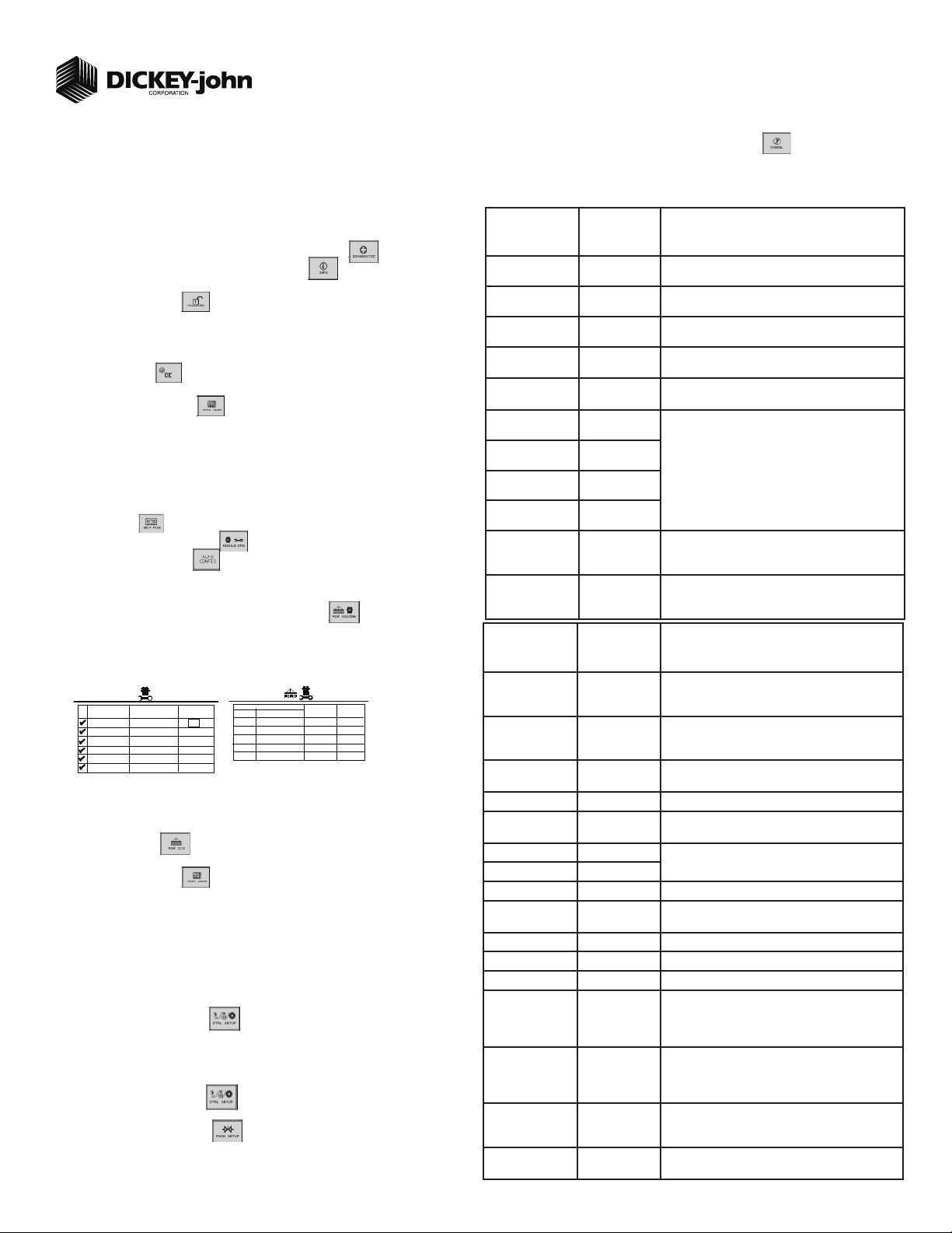
STEP 3: Auto Confi guration (identifi es sensors connected to each module)
Auto confi g is performed at the factory, but may need to be done in the fi eld as changes
are made to the system or if options are added to the base system.
Verify Auto Confi g results are correct. Check that the correct number of rows are assigned to
1.
the correct module and number of hoppers and pressure sensors are assigned accurately.
To Run Auto Confi g:
Press Next Page until Module Confi guration button appears.
1.
Press Module Confi guration button .
2.
Press AUTO CONFIG button .
3.
Hour glass will indicate system is detecting the presence of seed, pressure, or hopper
4.
sensors connected to each module and automatically assigns to the appropriate module.
When Auto Confi g completes, press the Row Assign button to display the Row
5.
Assignment screen to verify correct Row # is assigned to the correct module based on serial
number.
Enter # of rows assigned to each module.
6.
Module Configuration Screen
SERIAL
NUMBER
10001
10002
10003
10004
10005
10006
MODULE
MODULE
ADDR.
TYPE
WSMT-ACCGP
WSMB-18R
WSMB-18R
WSMB-18R
WSMB-18R
WSMB-18R
Above screens depict setup for 55 row
For 30 ft. 36 row (# of rows = 9) (4 towers)
For 35 ft. 40 row (# of rows = 8) (5 towers)
For 30 ft. 48 row (# of rows = 12) (4 towers)
STEP 4: Row Status/Row Width Setup
Press Row I/O button .
1.
Enter desired values using Table A as reference.
2.
Press Work Screen button to return to the Main Work screen.
3.
Proceed to Step 5C if a variable rate kit is installed.
STEP 5A: Material Confi guration Setup (Granular Seed Monitor)
16 different materials can be confi gured as seeding and fertilizer controls. Material defaults on
the Control Setup screen are Seed 1-4 (Granular Seed Control) Seed 5-8 (Granular Seed
Monitor) Fert 1-4 (Granular Fertilizer Control) Fert 5-8 (Granular Fertilizer Monitor).
Reference the System Confi guration section in the Operator’s Manual for additional setup
instructions.
Press the Control Setup button .
1.
At the Control Setup screen, select one of the 16 material buttons to edit (labeled Seed 1-8
2.
and Fert 1-8).
Enter desired values from Table B.
3.
Press the Control Setup button to return to the Control Setup screen.
4.
Repeat steps 2-4 for additional materials.
5.
Press the Channel Setup button to enter channel setup constants.
6.
11001-1460C-201107
©2011 DICKEY-john Corporation
Specifi cations subject to change without notice.
Seed Sensor Configuration Screen
ADDR.
1
2
3
4
5
6
2
3
4
5
6
bin) to be fertilizer. Reference the Operator’s manual for installation instructions.
TABLE A: Row
Status/Row
Width Setup
Row Width
(36 row) 30 ft.
Row Width
(40 row) 35 ft.
Row Width
(48 row) 30 ft.
Row Width
(55 row) 35 ft.
Auto Update Width Disabled When enabled, implement width will automatically calculate. If
Implement Width
(35 ft. 55 row) 7.5”
Implement Width
(35 ft. 40 row) 10”
Implement Width
(30 ft. 48 row) 7.5”
Implement Width
(30 ft. 36 row) 10”
On/Off Pattern Every row on On/Off Pattern indicates specifi c row patterns to be on or off. Select
Pop/Block Pattern Every row blockage Determines which sensors are used to calculate population and
TABLE B:
Gran Seed Mon
Material Setup
Matrl Label Seed 5 Material Name can be customized to accurately defi ne the
MODULE
WSMB-18R
WSMB-18R
WSMB-18R
WSMB-18R
WSMB-18R
TYPE
# OF
ROWS
11
11
11
11
11
ROW
1-11
12-22
23-33
34-44
45-55
#’s
Type Gran Seed Monitor Type of application control channel used for a specifi c material.
Display Units Lbs/Ac with
Target Rate 60 Desired rate of application in lbs/Ac.
Density 60.0 Establishes the density of material. Density units can be entered in
# Outlets per Meter Box 5 (35 ft) Establishes the number of towers for that channel.
# Outlets per Meter Box 4 (30 ft)
Calibration Constant 77600 Number of pulses to drop 1 cubic foot of material.
Variable Cal Constant Disabled Adjusts the accuracy of the seed mount dispensed based on the
Seeds per Pound 3000 Set to number of seeds per pound.
Low Shaft RPM 1 Set to desired min seed meter RPM.
High Shaft RPM 50 Set to desired max seed meter RPM.
High Pop Alarm 20 This is the percentage above the target population of the seeder
Low Pop Alarm 20 This is the percentage below the target population of the seeder
On/Off Pattern Every Row On On/Off Pattern indicates specifi c row patterns to be on or off. Select
Row Fail Rate 2/1 Sets the threshold for row failure alarms. Entered in seeds per
Default Value/
Value to Enter Instructions/Defi nitions
10 Enter row width distance in inches to calculate seed rate data (360).
10 Enter row width distance in inches to calculate seed rate data (400).
7.5 Enter row width distance in inches to calculate seed rate data (364).
7.5 Enter row width distance in inches to calculate seed rate data
416.5 Manually enter implement width in inches.
400
364
360
(416.5).
disabled, manually enter implement width.
pre-defi ned seeder All Row On pattern. For other seed patterns or
individual row settings, reference Operator’s Manual.
those used only for blockage detection. Select Every Row Blockage.
For other patterns, reference Operator’s Manual.
Default Value/
Value to Enter Instructions/Defi nitions
material’s type. Creating a name allows for quick identifi cation at
the Material Summary screen.
The Material Type must correctly match the Control Type to select
Material from the Material Summary screen and operate properly.
revs/acre
Displays primary and secondary readout units.
lbs/bu or lbs/ft
seed type. A selection of 25 pre-defi ned seed types are available.
channel if rows are assigned to the seeder channel. If rows are not
assigned to a seeder, this is the percentage above average seeder
population for all unassigned rows.
channel if rows are assigned to the seeder channel. If rows are not
assigned to a seeder channel, this is the percentage below average
seeder population for all unassigned rows.
pre-defi ned seeder All Row On pattern. For other seed patterns or
individual row settings, reference Operator’s manual.
second. 2/1 is a row failure threshold of 2 seeds in 1 second.
3
.
1
Page 2

Quick Setup Guide for IntelliAg Model NTA
TABLE C:
STEP 5B: Material Confi guration Setup
(Granular Fertilizer Monitor)
16 different materials can be confi gured as seeding and fertilizer
controls. Material defaults on the Control Setup screen are Seed
1-4 (Granular Seed Control) Seed 5-8 (Granular Seed Monitor)
Fert 1-4 (Granular Fertilizer Control) Fert 5-8 (Granular Fertilizer
Monitor). Reference the System Confi guration section in the
Operator’s manual for additional setup instructions.
Press the Control Setup button .
1.
At the Control Setup screen, select one of the 16 material
2.
buttons to edit (labeled Seed 1-8 and Fert 1-8).
Enter desired values from Table C.
3.
Press the Control Setup button to return to the Control
4.
Setup screen.
Repeat steps 2-4 for additional materials.
5.
Press the Channel Setup button to enter channel
6.
setup constants.
Step 5C only applies to those applications with a
variable rate kit option installed. Proceed to Step 6A if
variable rate is not applicable.
STEP 5C: Material Confi guration Setup
(Granular Seed or Fert Control)
16 different materials can be confi gured as seeding and fertilizer
controls. Material defaults on the Control Setup screen are Seed 14 (Granular Seed Control) Seed 5-8 (Granular Seed Monitor) Fert
1-4 (Granular Fertilizer Control) Fert 5-8 (Granular Fertilizer Monitor). Reference the System Confi guration section in the Operator’s
manual for additional setup instructions.
Press the Control Setup button .
1.
At the Control Setup screen, select one of the 16 material
2.
buttons to edit (labeled Seed 1-8 and Fert 1-8).
Enter desired values from Table D.
3.
Press the Control Setup button to return to the Control
4.
Setup screen.
Repeat steps 2-4 for additional materials.
5.
Press the Channel Setup button to enter channel setup
6.
constants.
Proceed to Step 6C if a variable rate kit is installed.
STEP 6A: Channel Setup (Granular Seed Monitor)
Channel 1 is generally used for granular seed monitor setup.
At the Channel Setup screen, verify that channel 1 is set to
1.
granular seed monitor.
Enter desired values using Table D as reference.
2.
To set up additional control channels (granular fert monitor,
3.
granular fert control, granular seed control, RPM Control),
press the Next Channel button .
When channel setup is complete, press the Work Screen but-
4.
ton to return to the Main Work screen.
Once a control channel has been established as granular seed
monitor, any new materials established as granular seed moni-
tor on the Material Setup screen will automatically be added
as optional materials for granular seed monitor channels on
the Control Setup screen.
11001-1460C-201107
©2011 DICKEY-john Corporation
Specifi cations subject to change without notice.
Material Setup
Gran Fert Monitor
Matrl Label Fert 5 Material Name can be customized to accurately defi ne the material’s type. Creating a
Type Gran Fert Monitor Desired type of application control channel being used for a specifi c material. The
Units Lbs/Ac with
Target Rate 50 Desired rate of application in lbs/Ac.
Density 60 Establishes the density of material in lbs/ft
# Outlets per Meter Box 5 (35 ft) Establishes the number of towers for that channel.
# Outlets per Meter Box 4 (30 ft)
Calibration Constant 82500 Number of pulses to drop 1 cubic foot of material.
Variable Cal Constant Disabled Adjusts the accuracy of the seed amount dispensed based on the seed type. A selec-
Low Shaft RPM 1 Set to desired min fert meter RPM.
High Shaft RPM 50 Set to desired max fert meter RPM.
On/Off Pattern Every Row On On/Off Pattern indicates specifi c row patterns to be on or off. Select pre-defi ned seed
Row Fail Rate 2/1 (2 seeds
TABLE D:
Material Setup
Gran Seed/Fert
Matrl Label Seed 1/Fert 1 Material Name can be customized to accurately defi ne the material’s type. Creating a
Type Gran Seed/Gran
Units Lbs/Ac Displays primary and secondary readout units in Lbs/ac or Kg/ha.
Target Rate 50 lbs/Ac Desired rate of application in lbs/Ac.
Inc/Dec % 1% Percent of change of entered target rate each time the Inc/Dec button is pressed.
Max Rate 78 lbs Max application rate in lbs per acre the control will allow.
Min Rate 48 lbs Min application rate in lbs per acre the control will allow.
Density 60 lbs/ft
# Outlets per Meter Box 5 (35 ft) Establishes the number of towers for that channel.
# Outlets per Meter Box 4 (30 ft)
Calibration Constant 82500 Pul/ft
Variable Cal Constant Disabled Adjusts the accuracy of the seed amount dispensed based on the seed type. A selec-
Low Shaft RPM 1 Set to desired min meter RPM.
High Shaft RPM 50 Set to desired max meter RPM.
Prod Level Alarm 0 Sets the weight to trigger alarm indicating low fertilizer levels in lbs.
Row Fail Rate 2/1 (2 seeds
TABLE E
Channel Setup
Gran Seed Mon
Type Gran Seed
Material Name Seed 5 Displays only materials that have been confi gured for the channel type.
Input Filter 50 Feedback frequency fi lter for the Control Channel. DO NOT CHANGE.
Sensor Constant 360 Sensor Constant establishes the number of pulses for one revolution of the feedback
Gear Ratio 1.0 Specifys the actual ratio from the feedback sensor to the seed meter shaft RPM. # of
# of Seed Rows
(determined by row
spacing)
Channel Width (35 ft.
55 row) 7.5”
Channel Width (35 ft.
40 row) 10”
Default Value/
Value to Enter Instructions/Defi nitions
revs/acre
every 1 second)
Default Value/
Value to Enter Instructions/Defi nitions
Fert Ctrl
3
/bu Establishes the density of material in lbs/ft3/bu.
3
every 1 second)
Default Value/
Value to Enter Instructions/Defi nitions
Monitor
40 or 55 row Entry of a specifi c number of seed rows to the Control Channel. Row assignment is
36 or 48 row
416.5 Manual entry of channel width for rows assigned to a specifi c channel. Width calcula-
400
name allows for quick identifi cation at the Material Summary screen.
Material Type must correctly match the Control Type to be able to select material from
the Material Summary screen and operate properly.
Displays primary and secondary readout units.
3
.
tion of 25 pre-defi ned seed types are available.
All Row On pattern. For other seed patterns or individual row settings, reference
Operator’s manual.
Set to desired number of seeds per second to trigger seed sensor failure alarm.
name allows for quick identifi cation at the Material Summary screen.
Desired type of application control channel being used for a specifi c material. The
Material Type must correctly match the Control Type to be able to select material from
the Control Setup screen and operate properly.
Number of pulses to drop 1 cubic foot/liter of material.
tion of 25 pre-defi ned seed types are available.
Set to desired number of seeds per second to trigger seed sensor failure alarm.
Set desired Channel Type as Gran Seed Monitor.
sensor. If a DICKEY-john application rate sensor is used, set value to 360.0.
revolutions feedback sensor turns in relation to one revolution the seed meter turns.
given a priority based on the Channel and will be assigned sequentially thereafter.
Channel 1 is always assigned to the fi rst set of rows, Channel 2 next set of rows, and
so on.
tion determined by # of seeder rows assigned to the channel multipled by the row
spacing.
Channel Width (30 ft. 48 row = 364)
Channel Width (30 ft. 36 row = 360)
2
Page 3

Quick Setup Guide for IntelliAg Model NTA
STEP 6B: Channel Setup (Granular Fertilizer Monitor)
Channel 2 is generally used for granular fertilizer monitor setup.
At the Channel Setup screen, press the Next Channel button
1.
to setup additional control channels.
Set channel 2 as granular fertilizer monitor.
2.
Enter desired values using Table F as reference.
3.
Continue to set up control channels 3 and 4, if required.
4.
Press the Work Screen Button when channel confi gu-
5.
rations are complete to return to the Main Work screen.
Once a Control Channel has been established as Granular Fertilizer Monitor, any new materials established as granular fertilizer
monitor on the Material Setup screen will automatically be added
as optional materials for granular fertilizer monitor channels on
the Control Setup screen.
Step 6C only applies to those applications with a
variable rate kit option installed. Proceed to step 7 if
variable rate is not applicable.
STEP 6C: Channel Setup (Granular Seed & Fertilizer
Control)
Press the Channel Setup button .
1.
Select an available channel and set to either granular seed
2.
control or granular fertilizer control.
Enter desired values using Table G as reference.
3.
To set up additional control channels, press the Next Channel
4.
button .
Press the Work Screen button when channel confi gu-
5.
rations are complete to return to the main menu.
TABLE F:
Channel Setup
Gran Fert Mon
Type Gran Fert Monitor Set desired Channel Type as Gran Fert Monitor.
Material Name Fert 5 Displays only materials that have been confi gured for the channel type.
Input Filter 50 Feedback frequency fi lter for the control channel. DO NOT CHANGE.
Sensor Constant 360 Sensor Constant establishes the number of pulses for one revolution of the feedback
Gear Ratio 1.0 Specifys the actual ratio from the feedback sensor to the seed meter shaft RPM.
Channel Width
(35 ft. 55 row) 7.5”
Channel Width
(35 ft. 40 row) 10”
Channel Width
(30 ft. 48 row) 7.5”
Channel Width
(30 ft. 36 row) 10”
Default Value/
Value to Enter Instructions/Defi nitions
sensor. If a DICKEY-john application rate sensor is used, the value should be set to
360.0.
Number of revolutions the feedback sensor turns in relation to one revolution the seed
meter turns.
416.5 Manual entry of the channel width for rows assigned to a specifi c channel. Width
400
364
360
calculation can be determined by # of seeder rows assigned to the channel multipled
by the row spacing.
TABLE G:
Channel Setup
Gran Seed &
Fert Setup
Type Gran Seed
Material Name Seed 1/Fert 1 Displays only materials that have been confi gured for the channel type.
Control Mode Auto Calculates application rates based on ground speed and channel width under normal
Drive Type Zero Max A Zero Max gear box controlled by a linear actuator for those applications with an
Drive Frequency 40 The Hz frequency for the linear actuator specifi ed by the valve manufacturer.
Input Filter 50 Feedback frequency fi lter for the control channel. DO NOT CHANGE.
Sensor Constant 360 Sensor constant establishes the number of pulses for one revolution of the feedback
Gear Ratio 1.0 Specifys the actual ratio from the feedback sensor to the seed meter shaft RPM.
Grd Spd/Trans In
Ratio
Meter Gear Range High/Low Determined by the position of the interchangeable gears. High range used for larger
# of Seed Rows 36 row Entry of a specifi c number of seed rows to the control channel. Row assignment is given
Channel Width
(35 ft. 55 row) 7.5”
Channel Width
(35 ft. 40 row) 10”
Channel Width
(30 ft. 48 row) 7.5”
Channel Width
(30 ft. 36 row) 10”
Flush Enable Disabled Not applicable to ground drive systems.
Precharge Time + 0.0 Not applicable to ground drive systems.
Delay Time - 0.0 Not applicable to ground drive systems.
Default Value/
Value to Enter Instructions/Defi nitions
Control/Gran Fert
Control
45 Ratio between distance traveled to one revolution of the input to the Zero Max transmis-
40 row
48 row
55 row
416.5 Manual entry of the implement width for rows assigned to a specifi c channel. Width
400
364
360
Set desired Channel Type as either Gran Seed Control or Gran Fertilizer Control.
operating conditions.
installed variable rate kit option.
sensor. If a DICKEY-john application rate sensor is used, the value should be set to
360.0.
Number of revolutions the feedback sensor turns in relation to one revolution the seed
meter turns.
sion. Ratio determines the input sprocket speed from the known ground speed.
seeds and higher seeding rates. Low range used for smaller seeds and lower seeding
rates. Refer to Great Plain’s operator’s manual for recommended high/low setting.
a priority based on the channel and will be assigned sequentially thereafter. Channel 1
is always assigned to the fi rst set of rows. Channel 2 next set of rows, and so on.
calculation can be determined by # of seeder rows assigned to the channel multipled by
the row spacing.
11001-1460C-201107
©2011 DICKEY-john Corporation
Specifi cations subject to change without notice.
3
Page 4

Quick Setup Guide for IntelliAg Model NTA
TABLE H:
STEP 7: Ground Speed Calibration Setup
Press the Speed Set button .
1.
Enter desired values using Table H as reference.
2.
Press the Work Screen button
3.
when Ground Speed Calibration confi gura-
tions are complete to return to the Main Work screen.
STEP 8: Accessory Sensor Setup
Hopper Setup
Press the Module Confi guration button .
1.
Press the Hopper Assign button .
2.
Verify # of hoppers is correct or enter # of hoppers assigned.
3.
Press the Hopper Set button .
4.
Enter desired values using Table I as reference.
5.
RPM Sensor Setup
Press the RPM Module button .
6.
Enter # of RPM sensors, if required.
7.
Press the RPM Setup button .
8.
Enter desired values using Table I as reference.
9.
Pressure Sensor Setup
At the Module Confi guration screen, press the PSI Module button .
9.
Verify # of pressure sensors or enter the # of pressure sensors assigned.
10.
Press the Pressure button .
11.
Enter desired values using Table I as reference.
12.
For additional information regarding hopper level, RPM, and pressure sensor setup,
reference the Operator’s manual.
STEP 9: Summary Screen
The Summary screen provides an overview of setup constants for active control channels.
At the Main Work screen, press the Next Page button .
1.
Press the Summary button
2.
To view specifi c control channel confi gurations, press the respective control chan-
3.
nel box 1-4.
Press inside a yellow highlighted box to open a specifi c screen for editing.
4.
Press the Work Screen button to return to the Main Work screen.
5.
Summary Screen
Ground Speed
Setup
Source Digital Frequency Select CAN Ground if radar is connected to ISO tractor cab har-
Gspd Constant 3440 Pul/400 Ft Input based on pulse count produced by the ground speed
Shutoff Speed 0.01 mph
Min Override 0.0 mph
Master Switch
Timeout
Ground Speed
Failure Alarm
Delay
Implement Lift Enabled Implement lift switch must be in the down position to operate.
TABLE I:
Accessory
Setup
# of Hoppers 2 # of hopper sensors connected to each module. # of hopper data
Hopper Logic
Level
Hopper Alarm
Delay
Channel
(Hopper #1)
Channel
(Hopper #2)
# of RPMs 1 Number of RPM sensors connected to each module to monitor a
High Alarm 4100 RPM Sets the RPM value at which a high RPM warning error is gener-
Low Alarm 2500 RPM Sets the RPM value at which a low RPM warning error is gener-
High Alarm Delay 5 sec Establishes the delay between the detection of a high RPM alarm
Low Alarm Delay 5 sec Establishes the delay between the detection of a low RPM alarm
RPM Constant 3 pul Number of pulses per sensor revolution.
RPM Filter 50% Filters the signal out of the RPM sensor.
Disable Control on
Low Alarm
# of Pressure
Sensors
High Alarm 20 oz/in
Low Alarm 4 oz/in
High Alarm Delay 5 sec Establishes the delay between the detection of a high pressure
Low Alarm Delay 5 sec Establishes the delay between the detection of a low pressure
Pressure Filter 50 Filters the signal out of the pressure sensor.
Default Value or
Value to Enter Instructions/Defi nitions
Default Value or
Value to Enter Instructions/Defi nitions
ness. Select Digital Frequency if radar or hall-effect is connected
to WSMT actuator harness.
sensor over 400’ distance. See Operator’s manual for calibration
instructions.
0.02 kph
0.0 kph
5 sec Determines the length of time before the system disables the
5 sec Set to desired number of seconds alarm sounds after the ground
Active Lo Sets the active state to low signifying that an alarm is generated
5 sec Controls the delay time between the detection of a high/low hop-
1 Assigns hopper sensor 1 to channel 1.
2 Assigns hopper sensor 2 to channel 2.
Disabled Allows for disabling of all control channels if the RPM value of the
2 Number of pressure sensors connected to each module to monitor
Indicates the minium ground speed allowed before the system
shuts off all control channels.
Minimum Override takes over when actual ground speed is below
the designated value. The control operates at this speed until
actual ground speed rises above the minimum override speed or
the actual speed drops below the shutoff speed.
operate function after ground speed is 0 if the master switch
remains in the ON position.
speed is zero and seed fl ow continues. (monitor only)
items for each listed module and the Hopp #’s value will automatically populate if Auto Confi g is used to confi gure installed sensors.
if the sensor’s output is in a low state. Use this setting if the connected sensor outputs a low condition when empty similar to the
DICKEY-john hopper sensor.
per alarm condition and the generation of the resulting alarm. The
value is entered in seconds.
shaft/fan.
ated.
ated.
condition and the resulting alarm display (entered in seconds).
condition and the resulting alarm display (entered in seconds).
selected sensor falls below the low alarm level setting.
pressure.
2
Sets the pressure value at which a high pressure warning error is
generated (oz/in
2
Sets the pressure value at which a low pressure warning error is
generated (oz/in
alarm condition and the resulting alarm display (entered in
seconds).
alarm condition and the resulting alarm display (entered in
seconds).
2
).
2
).
11001-1460C-201107
©2011 DICKEY-john Corporation
Specifi cations subject to change without notice.
4
Page 5

Quick Setup Guide for IntelliAg Model NTA
System Component Installation
Locate and install system components as shown in the diagram. Note how the modules are
1.
identifi ed and which modules are located on which sections in this system.
Connect WSMB module harnesses together with included extensions. Modules connect to
2.
the WSMT harness connection. Plug all unused connectors with included dust plugs.
Secure any excess wires with tie wraps.
3.
See Operator’s Manual for additional installation information.
4.
Power on monitor and program with correct constants as described on this Quick Start
5.
Guide.
Note: The pre-programmed constants in the monitor may cause an error code on the initial
power on of a new system. This is normal and can be cleared by pressing and holding
ESC
key for 2 seconds.
Connects to WSMT II
Aircart Main Harness
467980856
10’ Extension
467980141
Connect harnesses and accessory devices as
Rear Hitch
467980360
shown. Verify that outputs have
properly connected feedback sensor.
Tractor Cab Harness
467980455
Connect Cab Harness
to Implement Can
Implement CAN
Breakaway Harness
Multiple Lengths
Harness
467980131
Battery
+
-
Tractor ECU
467980451A
Harness only
35’
Harness
467980452
(A2 Terminal)
or Harness
467980451A
(A1 Terminal)
Connect to switched
must be connected to
Terminator
467980126
Ignition
+12VDC
NOTE: This wire
switched +12VDC
CAN
Chassis
Ground
Virtual
Terminal
Radar Speed Sensor
(Radar connected to either
tractor harness or WSMT
as shown below)
Implement CAN
Breakaway Harness
**
CAN Terminator
467980126
WSMB Module Harness
467981201 Dj SE style
*
467980134
Connect CAN
Terminator for
non-Blockage
application or 20’
Extension for
Blockage option
20’ Extension
467980140
467983502
Output
Module
467980476
467980475
Pressure Sensor
Front
Application Rate
Sensor Front
Application Rate
Sensor Rear
Clutch
10’ Extension
467980141
467981201 467981201
WSMB
Ground
Speed
Blockage option
467980474
Hopper Level
Sensor Front
Solenoid
Pressure Sensor
Rear
Hopper Level Sensor
WSMB
RPM
Fan
Rear
Fan
Zeromax
Labeled Front
and Rear
WSMT2
Module
ACCGP
5’ Extension
467980142
WSMT II
Aircart Main
Harness
467980856
467981201
WSMB
*
NTA 35’
40 row (rows 1-8 connected)
(rows 9-12 not connected plug w/464211090)
55 row (rows 1-11 connected)
(row 12 not connected plug w/464211090)
10’ Extension
467980141
467981201
CAN Terminator
467980126
WSMB
Connect CAN
**
Terminator with
Blockage option
11001-1460C-201107
©2011 DICKEY-john Corporation
Specifi cations subject to change without notice.
*
*
*
*
5
Page 6

Quick Setup Guide for IntelliAg Model NTA
System Component Installation
Locate and install system components as shown in the diagram. Note how the modules are
1.
identifi ed and which modules are located on which sections in this system.
Connect WSMB module harnesses together with included extensions. Modules connect to
2.
the WSMT harness connection. Plug all unused connectors with included dust plugs.
Secure any excess wires with tie wraps.
3.
See Operator’s Manual for additional installation information.
4.
Power on monitor and program with correct constants as described on this Quick Start
5.
Guide.
Note: The pre-programmed constants in the monitor may cause an error code on the initial
power on of a new system. This is normal and can be cleared by pressing and holding
ESC
key for 2 seconds.
Connects to WSMT II
Aircart Main Harness
467980856
10’ Extension
467980141
Connect harnesses and accessory devices as
Rear Hitch
467980360
shown. Verify that outputs have
properly connected feedback sensor.
Tractor Cab Harness
467980455
Connect Cab Harness
to Implement Can
Implement CAN
Breakaway Harness
Multiple Lengths
Battery
-
Harness
467980131
30’
+
Harness
467980452
(A2 Terminal)
or Harness
467980451A
(A1 Terminal)
Tractor ECU
467980451A
Harness only
Connect to switched
NOTE: This wire
must be connected to
switched +12VDC
Ignition
+12VDC
CAN
Terminator
467980126
Chassis
Ground
Virtual
Terminal
Radar Speed Sensor
(Radar connected to either
tractor harness or WSMT
as shown below)
Implement CAN
Breakaway Harness
467980134
467983502
Output
**
CAN Terminator
467980126
application or 20’
Blockage option
20’ Extension
467980140
WSMB Module Harness
467981201 Dj SE style
Connect CAN
Terminator for
non-Blockage
Extension for
Module
467980476
*
11001-1460C-201107
©2011 DICKEY-john Corporation
Specifi cations subject to change without notice.
467980475
Hopper Level
Sensor Front
Pressure Sensor
Front
Application Rate
Sensor Front
Application Rate
Sensor Rear
Clutch
Ground
Speed
Pressure Sensor
Rear
Hopper Level Sensor
Blockage option
10’ Extension
467980141
467981201 467981201
WSMB
5’ Extension
467980142
*
467980474
RPM
Fan
Solenoid
Rear
WSMB
*
Fan
Zeromax
Labeled Front
and Rear
WSMT2
Module
ACCGP
WSMT II
Aircart Main
Harness
467980856
10’ Extension
467980141
467981201
5’ Extension
467980142
WSMB
*
*
NTA 30’
36 row (rows 1-9 connected)
(rows 10-12 not connected plug w/464211090)
48 row (rows 1-12 connected)
CAN Terminator
467980126
**
Connect CAN
Terminator with
Blockage option
6
 Loading...