

Page 1

TABLE OF CONTENTS
Safety Notices ...................................................................................................... 1
System Overview ................................................................................................. 3
Virtual Terminal (VT).......................................................................................................... 3
Master Switch .................................................................................................................... 4
Working Set Master (WSMT) Module PDC (Planter Drill Control) ..................................... 4
Working Set Member (WSMB) Module (Optional) ............................................................. 5
Implement Lift Switch (Optional) ........................................................................................ 5
CAN Terminators ............................................................................................................... 5
System Requirements ......................................................................................... 7
Performance Features ....................................................................................................... 7
Compatibility ...................................................................................................................... 8
Installation ............................................................................................................ 9
Virtual Terminal.................................................................................................................. 9
Master Switch .................................................................................................................... 9
Working Set Master (WSMT) Module .............................................................................. 10
Working Set Member (WSMB) Module............................................................................ 12
Cab Harness Connections ............................................................................................... 16
Sensor Installation ........................................................................................................... 22
Seed Sensors.................................................................................................................................. 22
Hopper Level Sensors..................................................................................................................... 24
RPM/Fan Sensors ........................................................................................................................... 24
Air Pressure Sensors ...................................................................................................................... 24
System Modes.................................................................................................... 25
System Modes ................................................................................................................. 25
User Level Access ........................................................................................................... 25
Operate Mode .................................................................................................................. 25
Available Buttons in Operate Mode ................................................................................. 26
Next Channel .................................................................................................................................. 26
Next Screen .................................................................................................................................... 26
Increment ........................................................................................................................................ 26
Decrement....................................................................................................................................... 26
Inc/Dec Reset to Target .................................................................................................................. 26
Turn On/Off Channel....................................................................................................................... 27
Summary ......................................................................................................................................... 27
Setup/Configuration Mode ............................................................................................... 28
Available Buttons in Setup Mode ..................................................................................... 28
Planter Fill Disk ............................................................................................................................... 28
Row Monitor Setup.......................................................................................................................... 28
Control Setup .................................................................................................................................. 28
Speed Set ....................................................................................................................................... 29
Diagnostics...................................................................................................................................... 29
Alarm Log ........................................................................................................................................ 29
System Accumulators ..................................................................................................................... 29
Module Configuration ...................................................................................................................... 29
Screen Configuration ...................................................................................................................... 29
Planter Output Module (POM) Configuration (Optional) ................................................................. 29
Configuration ................................................................................................................................... 29
IntelliAg PDC User 2 & 3
11001-1501-200811
i
Page 2

TABLE OF CONTENTS
System Configuration ....................................................................................... 31
Control Setup Overview................................................................................................... 31
Material/Channel Setup Steps......................................................................................................... 31
Control Channel and Material Selection .......................................................................................... 33
Material Assignment (Matrl 1-16) .................................................................................................... 33
Material Setup ................................................................................................................................. 34
Create a Material Name .................................................................................................................. 34
Type................................................................................................................................................. 35
Units ................................................................................................................................................ 36
Preset Method Enabled ................................................................................................................... 36
Preset Method Disabled .................................................................................................................. 37
Material Setup Constants - Planter Ctrl ........................................................................... 38
Target Rate...................................................................................................................................... 38
Max Rate ......................................................................................................................................... 38
Min Rate .......................................................................................................................................... 38
Inc/Dec % ........................................................................................................................................ 38
Seeds Per Rev ................................................................................................................................ 39
Disc High Limit................................................................................................................................. 39
Disc Low Limit ................................................................................................................................. 39
Prod Level Alarm ............................................................................................................................. 39
High and Low Population Alarm ...................................................................................................... 39
Row Width ....................................................................................................................................... 40
On/Off Pattern ................................................................................................................................. 40
Row Fail Rate .................................................................................................................................. 40
Material Setup Constants-Gran Seed and Gran Fertilizer Control .................................. 41
Target Rate...................................................................................................................................... 41
Max Rate ......................................................................................................................................... 41
Min Rate .......................................................................................................................................... 41
Inc/Dec % ........................................................................................................................................ 41
Density............................................................................................................................................. 42
Spreader Constant .......................................................................................................................... 42
High Shaft RPM ............................................................................................................................... 42
Prod Level Alarm ............................................................................................................................. 42
Seeds Per Pound ............................................................................................................................ 43
High and Low Population Alarm ...................................................................................................... 43
Row Width ....................................................................................................................................... 43
On/Off Pattern ................................................................................................................................. 44
Row Fail Rate .................................................................................................................................. 44
Material Setup Constants-Liquid Flow............................................................................. 45
Target Rate...................................................................................................................................... 45
Max Rate ......................................................................................................................................... 45
Min Rate .......................................................................................................................................... 45
Inc/Dec % ........................................................................................................................................ 45
Low Flow Limit ................................................................................................................................. 46
High Flow Limit ................................................................................................................................ 46
Product Level Alarm ....................................................................................................................... 46
Material Setup - Monitor Only.......................................................................................... 47
Type................................................................................................................................................. 47
Target Population ............................................................................................................................ 47
High and Low Population Alarms .................................................................................................... 47
Row Width ....................................................................................................................................... 47
On/Off Pattern ................................................................................................................................. 48
Row Fail Rate .................................................................................................................................. 48
Material Setup Constants - RPM Control ........................................................................ 49
Target Rate...................................................................................................................................... 49
Max Rate ......................................................................................................................................... 49
Min Rate .......................................................................................................................................... 49
Inc/Dec % ........................................................................................................................................ 49
ii
IntelliAg PDC User 2 & 3
11001-1501-200811
Page 3

TABLE OF CONTENTS
Material Setup Constants - Granular Seed Monitor and Fertilizer Monitor ...................... 51
Target Rate ..................................................................................................................................... 51
Density ............................................................................................................................................ 51
Spreader Constant .......................................................................................................................... 51
Low Shaft RPM ............................................................................................................................... 51
High Shaft RPM .............................................................................................................................. 52
Prod Level Alarm............................................................................................................................. 52
Seeds Per Pound ............................................................................................................................ 52
High and Low Population Alarm...................................................................................................... 52
Row Width....................................................................................................................................... 53
On/Off Pattern ................................................................................................................................. 53
Row Fail Rate.................................................................................................................................. 53
Spreader Calibration ........................................................................................................ 53
Material Setup Constants - Split Air Regulation............................................................... 54
Target Rate ..................................................................................................................................... 54
Max Rate......................................................................................................................................... 54
Min Rate .......................................................................................................................................... 54
Inc/Dec %........................................................................................................................................ 54
Control Channel Setup..................................................................................................... 55
Planter Control Setup....................................................................................................... 56
Type ................................................................................................................................................ 56
Material Name ................................................................................................................................. 56
Control Mode................................................................................................................................... 56
Drive Type....................................................................................................................................... 57
Drive Frequency.............................................................................................................................. 57
Sensor Constant ............................................................................................................................. 57
Gear Ratio ....................................................................................................................................... 57
Number (#) of Seed Rows............................................................................................................... 57
Channel Width................................................................................................................................. 57
Precharge Time............................................................................................................................... 57
Flush Enable ................................................................................................................................... 59
Valve Calibration - Planter Control................................................................................... 60
Fill Disk............................................................................................................................................ 61
Fill Disk for a Control Channel ........................................................................................................ 61
Test Ground Speed ......................................................................................................................... 63
Row ................................................................................................................................................. 63
Test Target Pop .............................................................................................................................. 63
Test Seed Count ............................................................................................................................. 64
5 Rev Test........................................................................................................................ 65
Test Ground Speed ......................................................................................................................... 65
Row ................................................................................................................................................. 65
Test Target Pop .............................................................................................................................. 65
Test Seed Count ............................................................................................................................. 66
Remote Test Switch......................................................................................................... 66
Granular Seed and Granular Fert Setup.......................................................................... 67
Manual w/o Feedback ...................................................................................................................... 67
Valve Calibration - Gran Seed and Gran Fert.................................................................. 71
Channel On ..................................................................................................................................... 71
Limit Output ..................................................................................................................................... 72
Spreader Calibration - Gran Seed and Gran Fertilizer..................................................... 73
Density ............................................................................................................................................ 73
Spreader Constant .......................................................................................................................... 74
Target Meter RPM........................................................................................................................... 74
Number (#) Meter Revs................................................................................................................... 74
Pulse Count..................................................................................................................................... 74
New Spreader Constant .................................................................................................................. 74
Amount Dispensed.......................................................................................................................... 74
Shaft Turn ....................................................................................................................................... 74
IntelliAg PDC User 2 & 3
11001-1501-200811
iii
Page 4

TABLE OF CONTENTS
Liquid Flow Setup ............................................................................................................ 76
Manual w/o Feedback ..................................................................................................................... 76
Valve Calibration - Liquid................................................................................................. 79
Channel On ..................................................................................................................................... 79
Limit Output ..................................................................................................................................... 80
Liquid Flow Calibration .................................................................................................... 81
Initiating a Liquid Flow Calibration Procedure ................................................................................. 81
Granular Seed and Fertilizer Monitor Setup .................................................................... 83
Input Filter........................................................................................................................................ 83
Sensor Constant .............................................................................................................................. 83
Gear Ratio ....................................................................................................................................... 84
# Seed Rows ................................................................................................................................... 84
Channel Width ................................................................................................................................. 84
Spreader Calibration - Gran Seed Monitor and Gran Fertilizer Monitor .......................... 85
Density............................................................................................................................................. 85
Spreader Constant .......................................................................................................................... 86
Number (#) Meter Revs ................................................................................................................... 86
Pulse Count ..................................................................................................................................... 86
New Spreader Constant .................................................................................................................. 86
Amount Dispensed .......................................................................................................................... 86
RPM Control Setup.......................................................................................................... 87
Type................................................................................................................................................. 87
Material Name ................................................................................................................................. 87
Manual w/o Feedback ..................................................................................................................... 87
Drive Type ....................................................................................................................................... 88
Drive Frequency .............................................................................................................................. 88
Input Filter........................................................................................................................................ 88
Sensor Constant .............................................................................................................................. 88
Master Switch Off ............................................................................................................................ 88
Ramp Up/Down ............................................................................................................................... 88
Disable Control On Control Failure Alarm ....................................................................................... 89
Valve Calibration - RPM Control...................................................................................... 90
Channel On ..................................................................................................................................... 90
Limit Output ..................................................................................................................................... 91
Split Air Regulation Control ............................................................................................. 93
Type................................................................................................................................................. 93
Control Mode ................................................................................................................................... 93
Manual w/o Feedback ......................................................................................................................93
Drive Type ....................................................................................................................................... 93
Drive Frequency .............................................................................................................................. 94
Input Filter........................................................................................................................................ 94
Pressure Drop ................................................................................................................................. 94
Pressure Slope ................................................................................................................................ 94
Pressure Offset................................................................................................................................ 94
Planter Selection ..............................................................................................................................94
Sensitivity Adjust ..............................................................................................................................94
Module Configuration ...................................................................................................... 95
Serial Number and Module Type..................................................................................................... 95
Module Address............................................................................................................................... 96
Clutch Folding Module ..................................................................................................................... 96
Auto Sort.......................................................................................................................... 97
Auto Configuration........................................................................................................... 97
Auto Sort and Auto Config Examples .............................................................................. 98
Row Assignment............................................................................................................ 102
iv
IntelliAg PDC User 2 & 3
11001-1501-200811
Page 5

TABLE OF CONTENTS
Row Status/Row Width Setup........................................................................................ 103
Row Width..................................................................................................................................... 103
Auto Update Width ........................................................................................................................ 103
Imp Width ...................................................................................................................................... 104
On/Off Pattern ............................................................................................................................... 104
Blockage Pattern ........................................................................................................................... 105
Hopper Assignment ....................................................................................................... 106
# of Hoppers.................................................................................................................................. 106
Hopper Set..................................................................................................................... 107
Logic Level .................................................................................................................................... 107
Alarm Delay................................................................................................................................... 108
Channel......................................................................................................................................... 108
Accessory Assignment................................................................................................... 108
# Of Pressure/RPM Sensors ......................................................................................................... 109
RPM Setup..................................................................................................................... 109
High Alarm .................................................................................................................................... 109
Low Alarm ..................................................................................................................................... 110
High Alarm Delay .......................................................................................................................... 110
Low Alarm Delay ........................................................................................................................... 110
RPM Constant ............................................................................................................................... 110
RPM Filter ..................................................................................................................................... 110
Disable Control on Low Alarm....................................................................................................... 110
Pressure Sensor Setup.................................................................................................. 111
High Alarm .................................................................................................................................... 111
Low Alarm ..................................................................................................................................... 111
High Alarm Delay .......................................................................................................................... 111
Low Alarm Delay ........................................................................................................................... 112
Pressure Filter ............................................................................................................................... 112
Row Monitor Setup ........................................................................................................ 113
Material Name ............................................................................................................................... 113
High Alarm Delay .......................................................................................................................... 114
Low Alarm Delay ........................................................................................................................... 114
Population Adjust .......................................................................................................................... 114
Population Filter ............................................................................................................................ 114
Row Fail Rate................................................................................................................................ 114
Ground Speed Setup ..................................................................................................... 115
Source........................................................................................................................................... 115
GSPD Constant............................................................................................................................. 116
Shut Off Speed.............................................................................................................................. 116
Minimum Override ......................................................................................................................... 116
Master Sw Timeout ....................................................................................................................... 117
Ground Fail Alarm Delay............................................................................................................... 117
Precharge Ground Speed ............................................................................................................. 117
Flush Enable Speed...................................................................................................................... 117
Implement Lift................................................................................................................................ 117
Ground Speed Calibration ............................................................................................. 118
10” VT Aux Input/Function Assignment ......................................................................... 118
5” VT Aux Input/Function Assignment ........................................................................... 120
Work Screen Configuration............................................................................................ 123
Bargraph Setup ............................................................................................................................. 123
Return System Active Delay ......................................................................................................... 124
IntelliAg PDC User 2 & 3
11001-1501-200811
v
Page 6

TABLE OF CONTENTS
Data Items ........................................................................................................ 127
Clearing Accumulators .................................................................................................. 127
Control Actual Channels 1-4.......................................................................................... 127
Control Target Channels 1-4 ......................................................................................... 127
Control Rate Channels 1-4 ............................................................................................ 128
Control Scan.................................................................................................................. 128
Pop Row Scan............................................................................................................... 128
Pop Min Max Row Scan ................................................................................................ 128
Pop Min Row ................................................................................................................. 129
Pop Max Row ................................................................................................................ 129
Pop Avg ......................................................................................................................... 129
Spacing Row Scan ........................................................................................................ 129
Spacing Min Max Row Scan.......................................................................................... 129
Spacing Min Row........................................................................................................... 130
Spacing Max Row.......................................................................................................... 130
Spacing Avg .................................................................................................................. 130
Seed/Distance Row Scan .............................................................................................. 130
Seed/Distance Min Max Row Scan ............................................................................... 130
Seed/Distance Min Row ................................................................................................ 131
Seed/Distance Max Row ............................................................................................... 131
Seed/Distance Average................................................................................................. 131
Singulation Average ...................................................................................................... 131
Singulation Row Scan ................................................................................................... 131
Singulation Min Max Scan ............................................................................................. 131
Ground Speed ............................................................................................................... 132
Total Area ...................................................................................................................... 132
Field 1 Area ................................................................................................................... 132
Field 2 Area ................................................................................................................... 132
Channels 1 - 4 Area....................................................................................................... 133
Area Scan...................................................................................................................... 133
Control Feedback Scan ................................................................................................. 133
Area Per Hour................................................................................................................ 133
System Active Time ....................................................................................................... 133
Seed Count Accum Row ............................................................................................... 134
Distance Accumulator.................................................................................................... 134
Channels 1 - 4 Material Accum ..................................................................................... 134
Accessory Input Scan .................................................................................................... 134
Pressure Scan ............................................................................................................................... 134
RPM Scan ..................................................................................................................................... 135
Channel 1-4 Product Level ............................................................................................ 135
Hopper Level Status Scan............................................................................................. 135
Boom Status .................................................................................................................. 135
Guidance Status ............................................................................................................ 135
vi
IntelliAg PDC User 2 & 3
11001-1501-200811
Page 7

TABLE OF CONTENTS
System Operation ............................................................................................ 137
Row Fill (Split Air Regulation) ........................................................................................ 137
Pre-Operating Preparation............................................................................................. 137
Fill Disk ...........................................................................................................................137
Start ............................................................................................................................... 138
Stop................................................................................................................................ 139
Operate Screen Symbols............................................................................................... 140
Target Rate ................................................................................................................................... 140
Increase/Decrease % Rate ........................................................................................................... 140
Target Preset Rate ........................................................................................................................ 140
Implement Lift Switch .................................................................................................................... 140
Task Controller .............................................................................................................................. 140
Row Indicators .............................................................................................................................. 140
Autopilot Steering Navigation......................................................................................... 141
Accumulators ................................................................................................................. 141
Population Row Scan.................................................................................................................... 141
Singulation Average Population.................................................................................................... 141
Material Name ............................................................................................................................... 141
Population Max Row ..................................................................................................................... 142
Population Min Row ...................................................................................................................... 142
Precharge Feature ......................................................................................................... 143
Flush Enable .................................................................................................................. 144
System Information and Diagnostics ............................................................................. 145
Accumulators/Seed Count/Distance Screen.................................................................. 145
Powered On Time ......................................................................................................................... 145
System Active Time ...................................................................................................................... 145
System Active Area ....................................................................................................................... 146
Distance ........................................................................................................................................ 146
Diagnostics .................................................................................................................... 146
CH Setpoint ................................................................................................................................... 146
CH Target...................................................................................................................................... 147
CH Actual Rate ............................................................................................................................. 147
CH RPM/GPM ............................................................................................................................... 147
CH PWM ....................................................................................................................................... 147
CH Pulse Count ............................................................................................................................ 147
CH Freq Filt ................................................................................................................................... 147
Freq REL GSPD............................................................................................................................ 147
Freq Dig GSPD ............................................................................................................................. 147
Freq Press 1.................................................................................................................................. 147
IO Hopper 1................................................................................................................................... 148
IO Imp Lift...................................................................................................................................... 148
APP ID .......................................................................................................................................... 148
Sol PWR Volt ................................................................................................................................ 148
ECU PWR Volt .............................................................................................................................. 148
Snsr Pwr Volt ................................................................................................................................ 148
Gnd Volt ........................................................................................................................................ 148
Diagnostics Manual Valve Position................................................................................ 148
Manual Open of Channel .............................................................................................................. 149
Seed Count Screen........................................................................................................ 149
Information Screen......................................................................................................... 150
Resetting NOVRAM Values ........................................................................................... 151
Acknowledging Alarm Conditions .................................................................................. 151
Alarm Log....................................................................................................................... 152
Alarm Detail ................................................................................................................... 153
Alarm Reset .................................................................................................................................. 154
IntelliAg PDC User 2 & 3
11001-1501-200811
vii
Page 8

TABLE OF CONTENTS
Task Controller ................................................................................................ 155
Implement Offset ........................................................................................................... 155
Calculating Implement Offset ........................................................................................................ 155
Channel Linking ............................................................................................................................. 156
Material Application Rates ............................................................................................. 156
Import/Export Data ........................................................................................................ 157
Troubleshooting & Alarms ............................................................................. 161
Appendix .......................................................................................................... 171
Warranty............................................................................................................ 173
viii
IntelliAg PDC User 2 & 3
11001-1501-200811
Page 9

OPERATOR’S MANUAL
SAFETY NOTICES
Safety notices are one of the primary ways to call attention to potential
hazards.
This Safety Alert Symbol identifies important safety
messages in this manual. When you see this
symbol, carefully read the message that follows. Be
alert to the possibility of personal injury or death.
Use of the word WARNING indicates a potentially hazardous
situation which, if not avoided, could result in death or serious
injury.
Use of the word CAUTION with the Safety Alert Symbol indicates a
potentially hazardous situation which, if not avoided, may result in
minor or moderate injury.
Use of the word CAUTION without the safety alert symbol
indicates a potentially hazardous situation which, if not avoided,
may result in equipment damage.
IntelliAg PDC User 2 & 3
11001-1501-200811
SAFETY NOTICES / 1
Page 10

OPERATOR’S MANUAL
2 / SAFETY NOTICES
IntelliAg PDC User 2 & 3
11001-1501-200811
Page 11
OPERATOR’S MANUAL
SYSTEM OVERVIEW
The DICKEY-john IntelliAg Planter Drill Control system controls planting,
liquid, and granular applications. The IntelliAg is designed to ISO 11783
CAN communication standards providing the capability of communicating
with other manufacturer’s ISO 11783-compatible equipment.
The IntelliAg consists of:
• 5” Virtual Terminal or a 10” Virtual Terminal
• Master Switch
• Working Set Master Module
• Up to 11 Working Set Member Modules (monitors up to a total of 214
rows of seed input) (optional)
• Implement Lift (optional)
• CAN Terminators
• TECU (10” VT only)
• Video Surveillance (10” VT only)
All of the devices communicate using the ISO 11783 CAN communications
standard. System components are described in the following section.
NOTE: Examples shown throughout
this manual depict display
screens of the 10” Virtual
Terminal display.
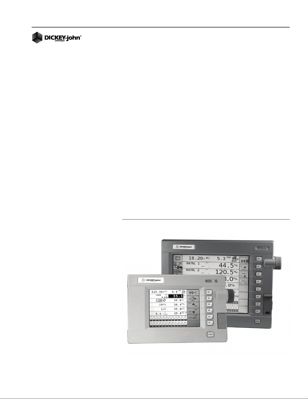
VIRTUAL TERMINAL (VT)
A 5” or 10” Virtual Terminal provides user interface with the IntelliAg system
used for output and input of data. Reference the VT operator’s manual for
setup and configuration instructions.
Figure 1
5” or 10” Virtual Terminal
IntelliAg PDC User 2 & 3
11001-1501-200811
SYSTEM OVERVIEW / 3
Page 12
OPERATOR’S MANUAL
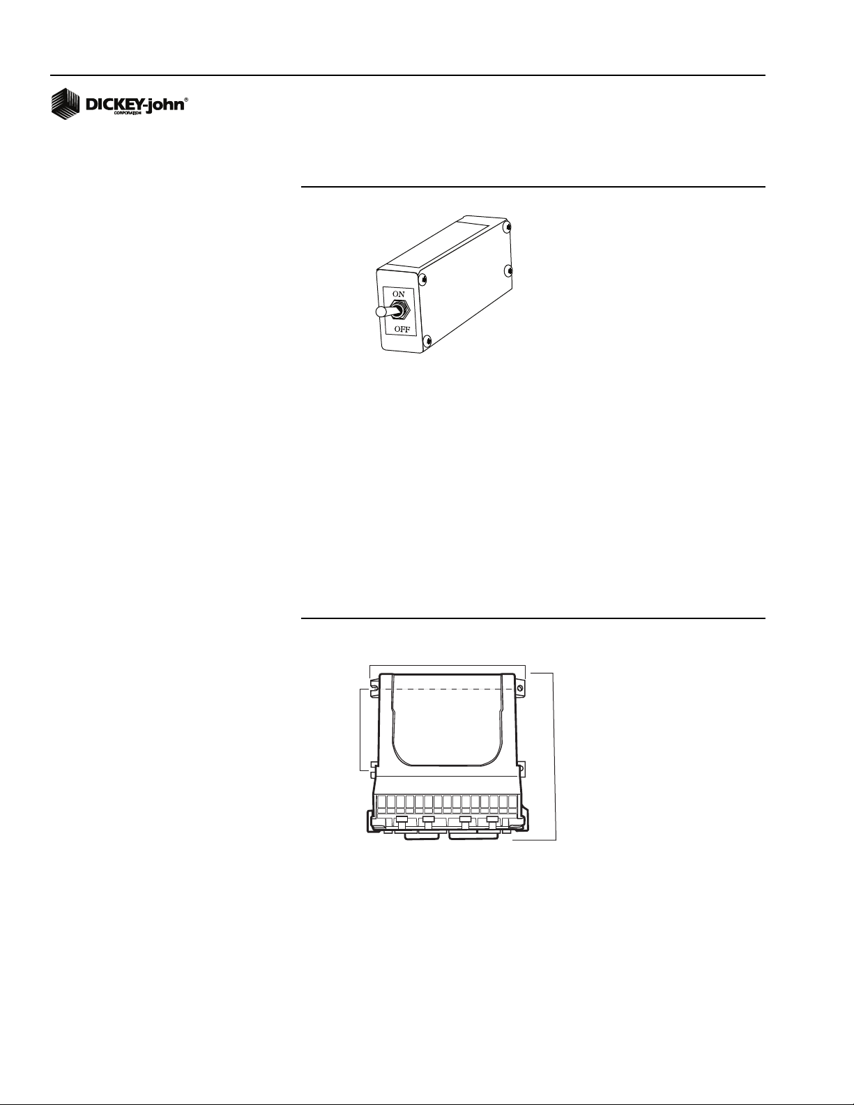
MASTER SWITCH
Figure 2
Master Switch
The Master Switch starts and stops product application through a single
switch. The two switch positions are ON and OFF. The normal operating
position for field application is ON. In this position, ground speed controls
the application rate. When ground speed is reduced to zero, all application
ceases. The OFF position inhibits all product flow. When set to the OFF
position, the system shuts off for safety and travel purposes. Setup and
configuration of the system is accomplished when the Master Switch is in
the OFF position. The Master Switch is also housed inside the cab of the
tractor.
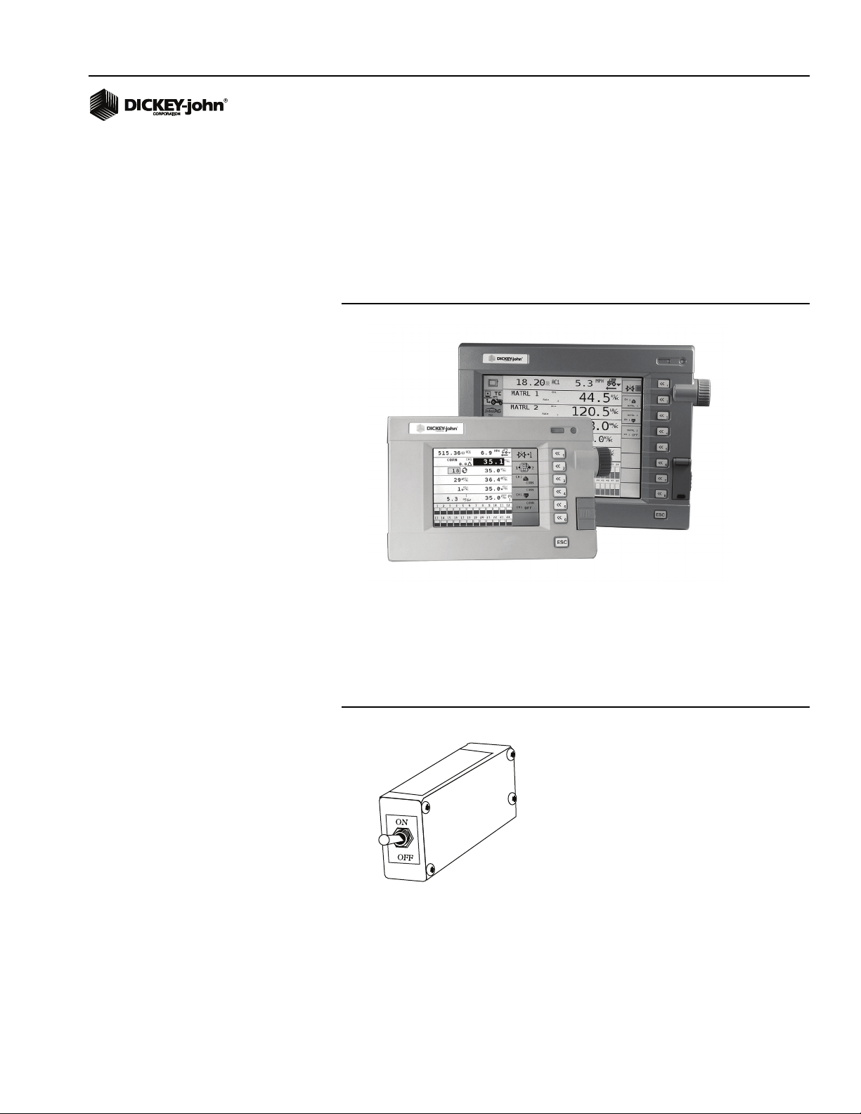
WORKING SET MASTER (WSMT) MODULE PDC
(PLANTER DRILL CONTROL)
Figure 3
Working Set Master Module
7.45”
7.0”
3.93”
6.80”
The Working Set Master (WSMT) module houses the system’s primary
interface device. All system parameters, constants and memory are stored
in the WSMT. The WSMT has four channels for planter, granular seeding,
granular fertilizer, liquid control or RPM. In addition, the WSMT can accept
inputs from 1 hopper level, 1 RPM or pressure sensor, 1 lift switch, 1 ground
speed sensor and up to 16 seed sensors. The WSMT module uses a 48-pin
connector with a jackscrew to secure the connector to the module. The
WSMT is typically mounted on the implement.
4 / SYSTEM OVERVIEW
IntelliAg PDC User 2 & 3
11001-1501-200811
Page 13

OPERATOR’S MANUAL
4.63
4.00
5.24
.291
2 holes
4.68
1.37
2.36
0.630
WORKING SET MEMBER (WSMB) MODULE
(OPTIONAL)
Figure 4
Working Set Member Module
Each Working Set Member (WSMB) module is an auxiliary to the Working
Set Master (WSMT). Each WSMB can accept up to 18 rows of seed
sensors. The WSMB passes information directly to the WSMT. Up to 11
WSMB’s can be installed to monitor up to 214 rows. The flexible design of
the WSMB allows for installation virtually anywhere on the implement.
IMPLEMENT LIFT SWITCH (OPTIONAL)
The Implement Lift Switch detects the position of the implement. When
using an Implement Lift Switch, the Master Switch can be left in the ON
position during operation, and the system will be turned OFF and ON as the
implement is raised and lowered. The Master Switch should be turned OFF
when in transport, when stationary, or when the operator has left the cab.
CAN TERMINATORS
CAN Terminators are necessary for proper communication between each
component of the system.
• One terminator is located on the cab harness, approximately 30 inches
from the Virtual Terminal connector.
• One terminator plugs into the implement harness of the last module
connected to the CAN bus.
Figure 5
Can Terminator
IntelliAg PDC User 2 & 3
11001-1501-200811
SYSTEM OVERVIEW / 5
Page 14

OPERATOR’S MANUAL
6 / SYSTEM OVERVIEW
IntelliAg PDC User 2 & 3
11001-1501-200811
Page 15

OPERATOR’S MANUAL
SYSTEM REQUIREMENTS
The minimum requirements to operate the IntelliAg Planter/Drill Control
system consist of:
• Virtual Terminal
•Master Switch
• Working Set Master
• Two CAN terminators
• TECU (10” VT only)
Optional and not required for system operation:
• Working Set Member(s)
• Clutch/Switch Folding Module and Planter Output Module
• Remote Test Switch (required for Continuous Test and 5 Rev Test)
PERFORMANCE FEATURES
• Three user access levels for viewing and setting constants
– User Level 1 (End User)
– User Level 2 (Dealer)
– User Level 3 (OEM)
• Monitoring of up to 214 rows, ground speed, one hopper level, one
shaft sensor, one lift switch
• Easy and flexible configuration
• View of functions including:
– control actual rates
– control target rates
– control rate
– control scan
– population row scan
– population min/max scan
– population min row
– population max row
– population average
– spacing row scan
– spacing min/max scan
– spacing min row
– spacing max row
– spacing average
– seeds per distance row scan
– seeds per distance min/max row scan
– seeds per distance min row
– seeds per distance max row
– seeds per distance average
– singulation average
– singulation row scan
– singulation min/max scan
IntelliAg PDC User 2 & 3
11001-1501-200811
SYSTEM REQUIREMENTS / 7
Page 16

OPERATOR’S MANUAL
Viewable functions continued-
– ground speed
– total area
– field area - 1 and 2
– channel areas 1-4
– area scan
– pressure scan
–RPM scan
– control feedback scan
– area per hour
– system active time
– seed count accumulator
– distance accumulator
– control channel material accumulation 1-4
– channel product level 1-4
– hopper level status scan
– boom status
– guidance status
COMPATIBILITY
• Compatible with DICKEY-john sensors
8 / SYSTEM REQUIREMENTS
IntelliAg PDC User 2 & 3
11001-1501-200811
Page 17
OPERATOR’S MANUAL
INSTALLATION
VIRTUAL TERMINAL
Reference the Virtual Terminal (VT) operator’s manual for installing the VT
to the tractor cab. Once the Virtual Terminal has been mounted, connect
the Tractor (Cab) Harness as illustrated in Figure 13 or Figure 14.
Figure 6
5” and 10” Virtual Terminals
MASTER SWITCH
1. Install the master switch within easy reach of the operator.
2. Once mounted, connect the master switch to the tractor (cab) harness
as illustrated in (Figure 13) or (Figure 14).
Figure 7
Master Switch
IntelliAg PDC User 2 & 3
11001-1501-200811
INSTALLATION / 9
Page 18
OPERATOR’S MANUAL
Figure 8
Working Set Master Module
7.45”
7.0”
3.93”
6.80”
WORKING SET MASTER (WSMT) MODULE
1. Select an area on the implement to mount the WSMT that allows for
easy hookup and access. Use the enclosure as a template to mark the
location of the mounting holes. Drill four 9/32 inch diameter holes
where marked.
IMPORTANT: Do not use the enclosure as a guide when drilling. Do
not overtighten nuts as this may damage the mounting
tabs of the enclosure.
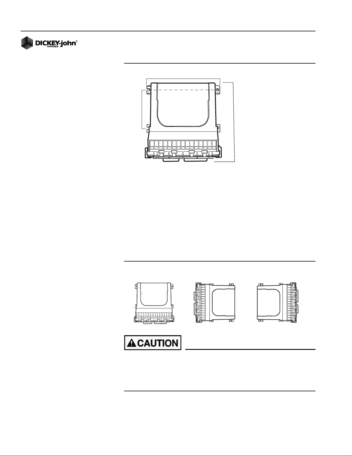
The WSMT may be mounted in any of the following orientations:
Figure 9
Acceptable Orientation
PREFERRED
ACCEPTABLE
ACCEPTABLE
Do not install the module in any orientation other than shown in
(Figure 9). The connection wires must not be mounted upward, as
moisture can collect inside the unit and damage the circuits.
Ensure that module connectors do not face upward when
implement is in a folded position as well.
10 / INSTALLATION
2. Mount with the label side of module facing out. Do not mount with the
connector facing up (see caution).
IntelliAg PDC User 2 & 3
11001-1501-200811
Page 19

OPERATOR’S MANUAL
3. Connect any additional adapter harnesses to the module harness. The
WSMT Module harness can accept the following adapter harnesses:
– Actuator Harness: This harness allows for up to 4 output control
channels, 4 control channel feedbacks, a hopper level sensor input,
a shaft sensor input, a ground speed input, and an implement
switch input. In addition, a pair of 6-pin connectors are available for
Servo connection which use FB1/FB2 respectively. Install sensors,
valves, etc. per the instructions included with the items. Install the
PWM valve assembly and feedback sensor for each control loop
and connect the devices to their respective inputs on the harness,
making certain to match PWM 1/Servo 1 with FB 1, PWM 2/Servo 2
with FB 2, etc. Secure any unused and excess cable lengths where
necessary. Refer to (Figure 15) for additional information.
– Seed Sensor Harness: This harness accommodates any standard
Dj Seed Sensor harness (PM style) or SE style harness depending
on the WSMT harness. A wide variety of harnesses are available to
accommodate various numbers of sensor inputs. Install all seed
sensors per the instructions included with the individual sensors.
Secure any unused or excess cable lengths as necessary.
IntelliAg PDC User 2 & 3
11001-1501-200811
INSTALLATION / 11
Page 20

OPERATOR’S MANUAL
4.00
.291
2HOLES
4.63
4.68
1.37
0.630
2.36
5.24
WORKING SET MEMBER (WSMB) MODULE
Figure 10
Working Set Member Module
IMPORTANT: For applications using multiple modules, it is
recommended that the WSMB’s are mounted on the
implement by increasing serial number order from left to
right. This step will minimize setup time at the Module
Configuration screen pressing the Auto Sort button will
group same module types together and in the order the
modules are mounted on the implement.
After Auto Sort is performed, modules will appear on the
Module Configuration screen in groups by serial number
order and module type.
1. Select an area on the implement to mount the member that allows for
easy hookup and access. Extensions may be used to reach members
installed on remote areas of the implement.
2. The module can be mounted in the same orientations as the Working
Set Master (WSMT) as illustrated in (Figure 9).
Do not install the module in any orientation other than illustrated
in (Figure 9). The connection wires must not be mounted upward
as moisture can collect inside the unit and damage the circuits.
Ensure that module connectors do not face upward when
implement is in a folded position as well.
3. Mount with the label side of the module facing out.
4. To bolt the member to a frame:
• Use the enclosure as a template to mark the location of the mounting
holes.
• Drill two 9/32 inch diameter holes where marked.
• Attach to frame using 1/4 x 20 bolts or other fastening devices as
illustrated in (Figure 11).
12 / INSTALLATION
IntelliAg PDC User 2 & 3
11001-1501-200811
Page 21
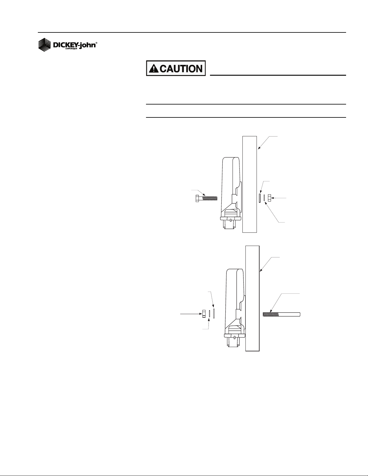
OPERATOR’S MANUAL
Do not use the enclosure as a guide when drilling. Do not
overtighten nuts as this may damage the mounting tabs on the
enclosure.
Figure 11
Working Set Member Installation (Bolted)
IMPLEMENT
FRAME
1/4 FLAT WASHER
1/4 x 20 BOLT
1/4 NUT
1/4 FLAT WASHER
1/4 NUT
1/4 SPLIT LOCKWASHER
1/4 SPLIT
LOCKWASHER
IMPLEMENT
FRAME OR
SUPPORT
1/4 x 20
THREADED "U"
BOLT OR
OTHER
FASTENING
DEVICE
IntelliAg PDC User 2 & 3
11001-1501-200811
INSTALLATION / 13
Page 22

OPERATOR’S MANUAL
IMPLEMENT
FRAME
5. To tie-strap the member to a frame:
• Use one long tie-strap to loop around the member body and through
both mounting holes as illustrated in (Figure 12).
• If necessary, drill mounting holes following the procedure described
above.
• Securely tighten tie-strap.
• Install a second tie-strap toward the label end of the enclosure for
additional support.
Figure 12
Working Set Member Installation (Tie-Strap)
6. Connect a WSMB harness to the WSMB module and connect the
WSMB harness to the Power/CAN backbone, refer to (Figure 16).
7. Connect each module harness to its module, inserting both connectors
until the connector locking tabs engage.
8. Lay out the planter harness along the frame of the implement to each
of the seed sensors. For seed sensors, extensions will most likely not
be necessary.
9. Route sensor wires in locations where they will not be damaged by
chains, drive shafts, sprockets, etc.
10. Secure the harness to the toolbar with a minimum of 3” straight wire
exiting the module before bending and attaching with tie-straps ensure
good wire sealing.
11. Coil and secure any unused sensor connections.
12. The WSMB Module harness can accept a standard DICKEY-john PM
style planter harness (single round 37-pin connector) or an SE style
planter harness (1 gray 12-pin, 1 black 12-pin rectangular connector)
depending on the WSMB harness used. Harnesses are available for a
number of row configurations.
• Route the planter harness on the implement, securing as necessary.
• Install seed sensors per the instructions included with the sensors.
Refer to the implement harness diagram for additional information
(Figure 13) or (Figure 14).
14 / INSTALLATION
IntelliAg PDC User 2 & 3
11001-1501-200811
Page 23

OPERATOR’S MANUAL
NOTE: The last module harness in the
system must have a CAN
Terminator installed for proper
system operation. Refer to
Implement Harness (Figure 13)
or (Figure 14) for additional
information.
IMPORTANT: Be sure the locking tabs engage when inserting the
connectors. The connection is sealed only when the
locking tabs have fully engaged.
IntelliAg PDC User 2 & 3
11001-1501-200811
INSTALLATION / 15
Page 24
OPERATOR’S MANUAL
Battery
+
-
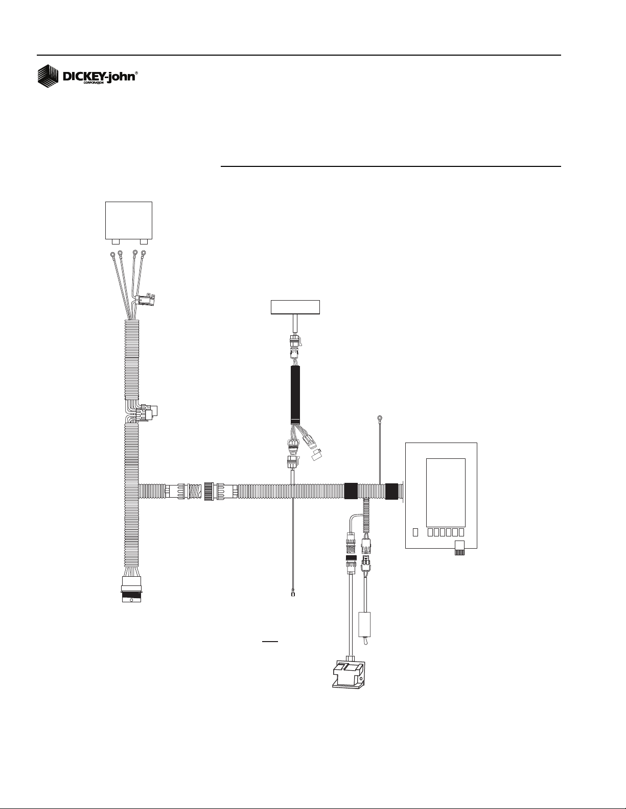
CAB HARNESS CONNECTIONS
The following diagrams illustrate cab harness layout and connections for
DICKEY-john 5” and 10” Virtual Terminals.
Figure 13
Cab Harness Layout and Connections (5” Virtual Terminal)
CFM (optional)
System Power Harness
467980455
To Implement CAN
Harness
Tractor
Harness
467980452
Connect to switched
must be connected to
switched +12VDC
Ignition
+12VDC
NOTE: This wire
Chassis
Ground
CAN
Terminator
467980126
Virtual
Terminal
467980501
Master
Switch
467980124S1
Radar Speed Sensor
(if not connected to WSMT)
16 / INSTALLATION
IntelliAg PDC User 2 & 3
11001-1501-200811
Page 25

OPERATOR’S MANUAL
NOTE: The ignition lead must be
connected to switched +12VDC
for the system to power up and
down properly.
5” VIRTUAL TERMINAL CAB HARNESS CONNECTIONS
1. Connect the power leads directly to the battery.
2. Connect the ignition wire to a switched +12VDC.
3. Connect the Chassis Ground lead to a bare point of the cab frame that
offers a good chassis ground connection.
4. Connect the Master Switch, CAN Terminator and Radar Speed Sensor
to their respective connectors on the cab harness. If the Speed Sensor
is to be connected to the WSMT, do not connect anything to the Speed
Sensor connector on the Cab Harness.
IntelliAg PDC User 2 & 3
11001-1501-200811
INSTALLATION / 17
Page 26
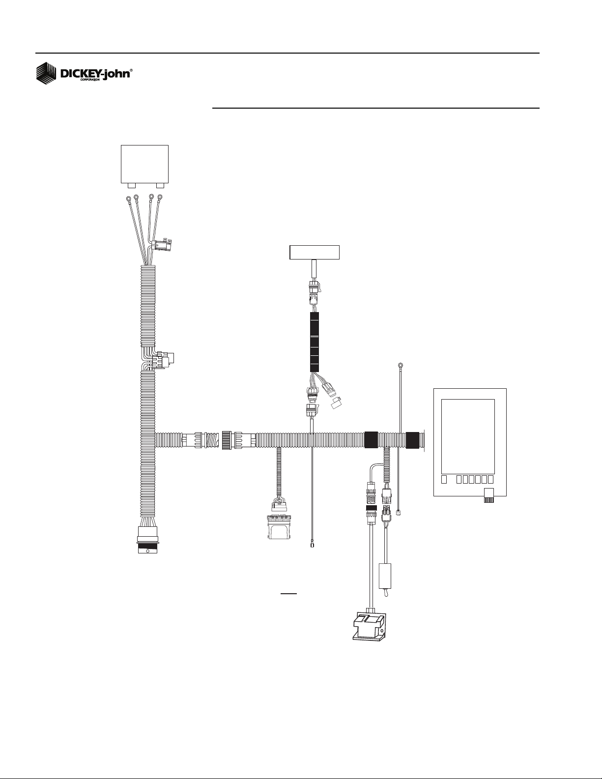
OPERATOR’S MANUAL
Battery
+
-
Figure 14
Implement Harness Connections (10” Virtual Terminal)
CFM (optional)
System Power
Harness
467980455
To Implement CAN
Harness
Tractor
ECU
467985060S1
Tractor
Harness
467980451A
Connect to switched
NOTE: This wire
must be connected to
switched +12VDC
Ignition
+12VDC
CAN
Terminator
467980126
Chassis
Ground
RS232
GPS
Master
Switch
467980124S1
Virtual
Terminal
467980503
18 / INSTALLATION
Radar Speed Sensor
(If not connected to WSMT)
IntelliAg PDC User 2 & 3
11001-1501-200811
Page 27

OPERATOR’S MANUAL
NOTE: The ignition lead must be
connected to switched +12VDC
for the system to power up and
down properly.
10” VIRTUAL TERMINAL CAB HARNESS CONNECTIONS
Connect the power leads directly to the battery.
1. Connect the ignition wire to a switched +12VDC.
2. Connect the Chassis Ground lead to a bare point of the cab frame that
offers a good chassis ground connection.
3. Connect the Master Switch, CAN Terminator, Radar Speed Sensor,
GPS, and Tractor ECU to their respective connectors on the cab
harness. If the Speed Sensor is to be connected to the WSMT, do not
connect anything to the Speed Sensor connector on the Cab Harness.
IntelliAg PDC User 2 & 3
11001-1501-200811
INSTALLATION / 19
Page 28
OPERATOR’S MANUAL
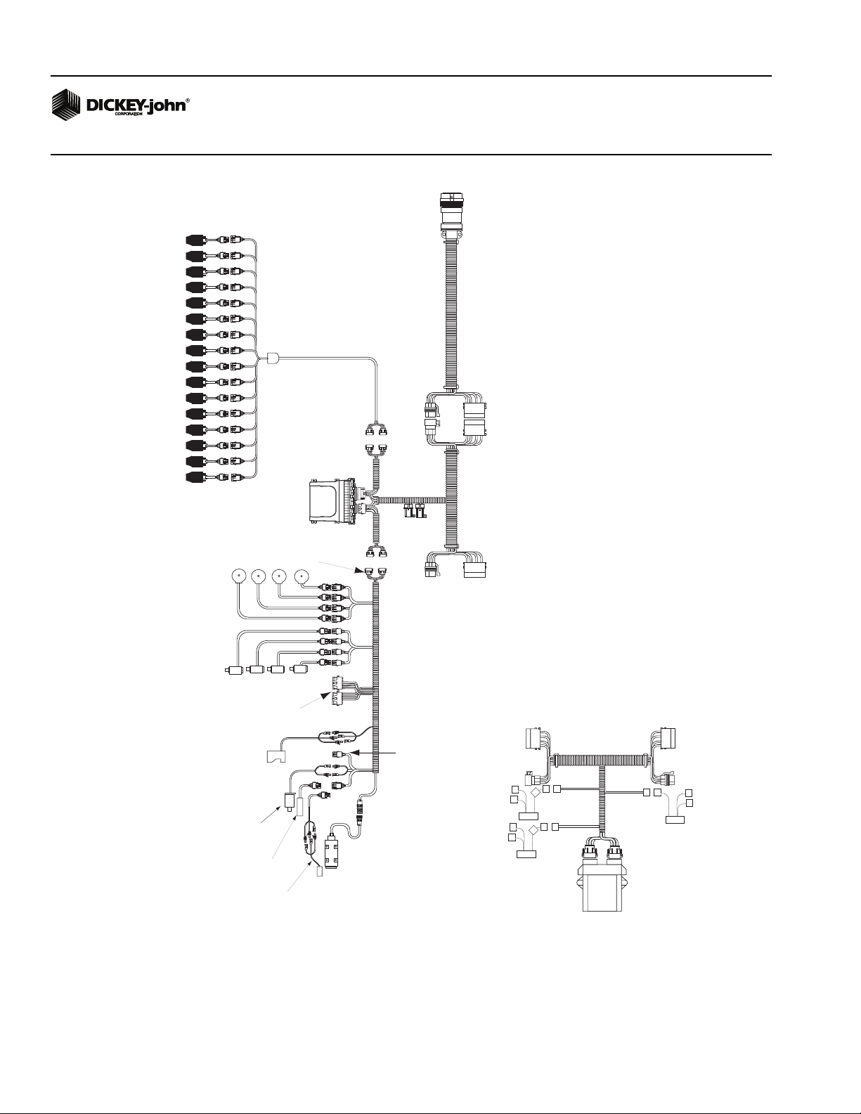
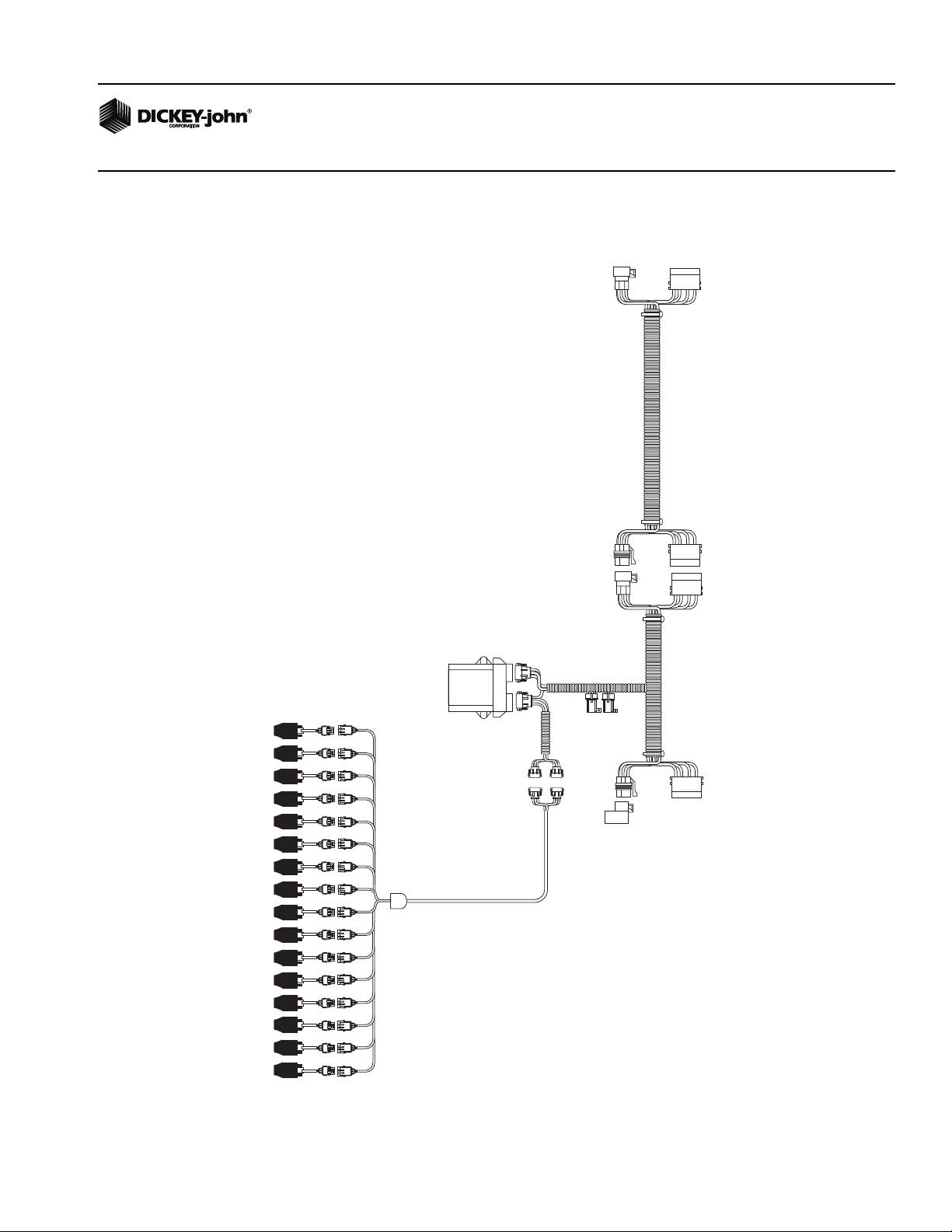
Figure 15
Implement Harness
Connect harnesses and accessory devices as
shown. Verify that PWM Solenoid Valves have a
properly connected feedback sensor.
Connect to
Cab Harness
.
Implement CAN Breakaway Harness
46798013X (multiple lengths)
Standard Dj SE Style
Planter Harness
NOTE: Connect the WSMT Actuator Harness
and the Dj Planter Harness to the mating
connectors of the WSMT Module Harness
Application Rate
Sensors x 4
(Channel 1-4 Feedback)
Labeled FB1-FB4
PWM Solenoid
Valves
Channel 1-4
Control
Labeled PWM 1-PWM 4
Servo Valve
Connectors
Hopper Level Sensor
Labeled HOPPER 1
Implement Lift Sensor
Labeled IMP LIFT
If no Implement Lift
Sensor is used, connect
the IMP LIFT leads
together
Fan/Shaft RPM Sensor
Labeled RPM1 or
Air Pressure
Sensor 46682-0920S1
46798081S1
WSMT
MODULE
PLANTER/DRILL
CONTROL
Accessory Sensor
Connection
Connect to next module
harness or implement
extension harness
(See Figure 15)
(Connect CAN terminator
if this is the last module
on the CAN bus)
WSMT Actuator Harness
46798016X
Remote
Test Swtich
Radar Speed Sensor
Labeled GND Speed
WSMT Module Harness
46798085X
Switch 5
Switch 6
464820510
Switch 3
Switch 4
464820510
OPTIONAL
467983500
Planter
Output
Module
46798200051
Switch 1 (Output 1)
Switch 2 (Output 2)
464820510
20 / INSTALLATION
IntelliAg PDC User 2 & 3
11001-1501-200811
Page 29
OPERATOR’S MANUAL
Figure 16
Implement Harness (Continued)
From Previous
Module Harness or
Extension Harness
(See Figure 15)
Implement CAN Extension
Harness 46798014X
(Multiple Lengths)
WSMB
Module
Seed Monitor
Standard Dj SE Style
Planter Harness
467981100S1
CAN
Terminator
WSMB Module
Harness
46798120X1
Connect to next module
harness or implement
extension harness
(Connect CAN terminator
if this is the last module
on the CAN bus)
IntelliAg PDC User 2 & 3
11001-1501-200811
INSTALLATION / 21
Page 30

OPERATOR’S MANUAL
1. Connect the Implement CAN Breakaway extension to the mating
connector of the Cab Harness. Route the harness along the implement
hitch to the WSMT module harness (use an Implement Extension
Harness if additional length is needed). Secure harness as needed.
2. Connect the Module Harness to the mating connectors of the
Implement CAN harness, and then connect the module to the harness.
The WSMT module uses a 30 and 18 way connector with a jackscrew
to secure the connector to the module. The WSMB uses a pair of
12-pin connectors. Secure module harness as needed.
SENSOR INSTALLATION
For proper system operation, all sensors used with the system must be
connected properly as described in the following sections. Sensors that are
incorrectly installed will not be properly identified by the system and will
result in incorrect numbering of the sensors.
SEED SENSORS
The system is compatible with all existing DICKEY-john seed sensors.
Seed sensors may be connected to the WSMT module and all WSMB
Planter Monitor Modules. Any number of sensors up to the maximum
capacity of the module may be connected. A maximum of 214 seed sensors
can be connected to the system.
22 / INSTALLATION
IntelliAg PDC User 2 & 3
11001-1501-200811
Page 31

OPERATOR’S MANUAL
When connecting seed sensors to the modules, the following requirements
must be observed:
All seed sensors installed must be connected to the seed sensor
harness SEQUENTIALLY, starting with the Row 1 input. In the event
that not all row inputs on the module will be used, the unused inputs
must be the last inputs on that module.
Figure 17
Correct Seed Sensor Module Connection
CORRECT
Module Seed Sensor
Harness
Row1Row2Row
3
Row
Row
Row6Row7Row8Row
5
4
CORRECT
Module Seed Sensor
Row1Row2Row
3
Row
Row
Row6Row7Row8Row
5
4
Figure 18
Incorrect Seed Sensor Module Connection
INCORRECT
Module Seed Sensor
9
Harness
9
Harness
Row
10
Row
10
Row
11
Row
11
Row
12
Row
12
IntelliAg PDC User 2 & 3
11001-1501-200811
Row1Row2Row
3
Row
4
Row
Row6Row7Row8Row
5
Row
Row
9
10
Row
11
12
Failure to correctly install seed sensors will result in incorrect row
assignment on the planter monitor display functions and alarms.
INSTALLATION / 23
Page 32

OPERATOR’S MANUAL
HOPPER LEVEL SENSORS
The system is compatible with the DICKEY-john planter hopper level
sensors. One hopper level sensor can be connected to the actuator
harness and another 4 hopper sensors can be connected using an
additional harness. Both harnesses are connected to the WSMT. Hopper
level connections are labeled HOPPER 1, 2, 3, etc.
RPM/FAN SENSORS
The system is compatible with all existing DICKEY-john digital Fan/RPM
sensors. One Fan/RPM sensor can be connected to the WSMT module.
The sensor is connected to the actuator harness. The Fan/RPM sensor
connection is labeled RPM 1.
AIR PRESSURE SENSORS
The system is compatible with DICKEY-john air pressure sensors. One air
pressure sensor with adapter harness connects to the RPM harness
connection labeled RPM 1.
24 / INSTALLATION
IntelliAg PDC User 2 & 3
11001-1501-200811
Page 33

OPERATOR’S MANUAL
SYSTEM MODES
The Virtual Terminal has two modes of operation:
•Operate
• Setup/Configuration (Setup constants accessible only with password)
The position of the master switch determines which mode is selected.
USER LEVEL ACCESS
The system has three user levels:
• User Level 1: Operator View
• User Level 2: Setup of constants (system configuration)
• User Level 3: Setup of constants and alarm log reset
The system loads in User Level 1 at every power cycle. Access to User
Level 2 and 3 screens require a password available through Great Plains
Service.
OPERATE MODE
When the Master Switch is in the ON position, the Virtual Terminal (VT) is in
Operate mode. In this mode, all enabled system components and control
channels are operational, as well as all monitoring functions and system
accumulators.
Figure 19
Operate Mode
185
IntelliAg PDC User 2 & 3
11001-1501-200811
SYSTEM MODES / 25
Page 34

OPERATOR’S MANUAL
AVAILABLE BUTTONS IN OPERATE MODE
Virtual buttons on the display are used to interact with the system.
Top-level buttons that appear on the Operate and Setup/Configuration
screens are defined below.
NEXT CHANNEL
The Next Channel button selects the next available channel to be active
and viewable, as illustrated in Figure 20, “Channel 1”. The active channel
can be set to ON or OFF by selecting the Turn On/Off Channel button. The
active channel is displayed in reverse video display in a multiple channel
configuration.
The Target Rate can be adjusted by using the Inc/Dec buttons. The Next
Channel button advances to the next available channel information. The
channel’s Inc/Dec buttons, as well as the ON/OFF buttons, display the
current channel label. This key is visible only when multiple channels have
been configured.
NEXT SCREEN
The Next Screen button displays the next configured work screen. The
number to the left of the graphic identifies the current screen. The number
on the right identifies the next screen to display. The Next Work Screen only
displays if multiple screens are configured.
INCREMENT
The Increment button increases the active channel’s target rate by the
amount specified in the Inc/Dec % or rate table setup for that material.
Increment can be pressed several times to increase the target rate by the
specified amount for every actuation, until the maximum rate value or
preset value is reached. The active channel/material is displayed in the
button text.
DECREMENT
The Decrement button decreases the active channel’s target rate by the
amount specified in the Inc/Dec% or rate table setup for that material.
Decrement can be pressed several times to reduce the target rate by the
specified amount for every actuation, until the minimum rate value or preset
value is reached. The active channel/material is displayed in the button text.
INC/DEC RESET TO TARGET
The Inc/Dec Reset to Target button is used to return the active channel to
the original material target rate. This button is only available for channels
that are active and have had the target rate adjusted using the Increment or
Decrement buttons in inc/dec % mode. The active channel displays in the
button text.
26 / SYSTEM MODES
IntelliAg PDC User 2 & 3
11001-1501-200811
Page 35

OPERATOR’S MANUAL
TURN ON/OFF CHANNEL
The Turn On/Off Channel buttons turn the active channel ON and OFF,
respectively. Channels that are set to OFF will not operate when the master
switch is set to the ON position. Turning a channel OFF is not the same as
disabling a channel in Channel Setup Mode. The active channel is
displayed in the button text. If the key text is OFF, this is the action that will
be performed when the key is pressed.
SUMMARY
The Summary button accesses the Summary screen and provides an
overview of system configurations for enabled channels. Specific setup
screens can be accessed (Level 2 and 3 Users only) by pressing inside the
yellow boxes for Channel, Material, Row, Module, Speed Set, and
Accessory Sensor screens.
IntelliAg PDC User 2 & 3
11001-1501-200811
SYSTEM MODES / 27
Page 36

OPERATOR’S MANUAL
SETUP/CONFIGURATION MODE
When the master switch is in the OFF position, the VT is in Setup/
Configuration mode. In this mode, all control and monitoring functions
cease. A password is required to access this mode.
Figure 20
Setup/Configuration Mode
Setup
Screen 1
Buttons
Setup
Screen 2
Buttons
Setup
Screen 3
Buttons
AVAILABLE BUTTONS IN SETUP MODE
Additional buttons for system configuration and parameter setup functions
are enabled and only appear in setup/configuration mode. Refer to the
System Configuration section for information on these functions.
PLANTER FILL DISK
The Planter Fill Disk button is used to fill the seed meters with seed to allow
instant seed flow when the channel is turned ON. Pressing the Fill Disk
button rotates the seed meters on ALL ACTIVE planter control channels
one revolution, then stops. For additional information, refer to the System
Configuration section.
ROW MONITOR SETUP
The Row Monitor Setup button accesses the Row Monitor Setup screen. All
user-entered constants relating to general planter monitor functions are
accessed on this screen.
CONTROL SETUP
28 / SYSTEM MODES
The Control Setup button accesses the Control Setup screen. Up to 16
different materials can be configured and stored for planter, liquid, fertilizer,
RPM control, and monitor only.
IntelliAg PDC User 2 & 3
11001-1501-200811
Page 37

OPERATOR’S MANUAL
SPEED SET
The Speed Set button accesses the Ground Speed Setup screen. Ground
speed is the rate in MPH (Km/h) as measured by the ground speed sensor.
DIAGNOSTICS
The Diagnostics button accesses the Diagnostics screen. Various system
operating parameters display on this screen. There is no user-entered data
on this screen.
ALARM LOG
The Alarm Log button accesses the Alarm Log screen. An account of the
previous alarms issued is stored here. There is no user-entered data on this
screen. Not all alarms are recorded in the alarm log.
SYSTEM ACCUMULATORS
The System Accumulators button accesses the System Accumulators
screen. All of the system accumulators for time and distance display on this
screen. There is no user-entered data on this screen.
MODULE CONFIGURATION
The Module Configuration button accesses the Module Configuration Setup
screen. All user-entered data pertaining to module configuration is
established on this screen.
SCREEN CONFIGURATION
The Screen Configuration button accesses the Screen Configuration Setup
screen. The Virtual Terminal can be customized to display any combination
of data items available. Up to three individual display screens can be
customized. All work screen configurations are established on this screen.
PLANTER OUTPUT MODULE (POM) CONFIGURATION
(OPTIONAL)
The POM Configuration button accesses the POM Setup screen. This
screen is only accessible when using a Planter Output Module for clutch/
frame control.
CONFIGURATION
The Configuration button accesses the Import/Export Configuration screen.
System configurations can be exported to an SD card and imported to other
Working Set Masters eliminating manual data entry.
IntelliAg PDC User 2 & 3
11001-1501-200811
SYSTEM MODES / 29
Page 38

OPERATOR’S MANUAL
30 / SYSTEM MODES
IntelliAg PDC User 2 & 3
11001-1501-200811
Page 39

OPERATOR’S MANUAL
SYSTEM CONFIGURATION
The following parameters must be defined for effective system operation:
• Control Channel Setup
• Material Setup
• Ground Speed Setup and Calibration
• Module Configuration (Working Set Master and Members)
• Control Channel Implement Offsets (for GPS and/or field
accumulators)
CONTROL SETUP OVERVIEW
The Control Setup screen provides an overview of all materials that have
been assigned and configured for a control channel.
The Control Setup screen has control channel selection at the top of the
screen and all assigned and unassigned material names at the bottom half
of the screen. (Figure 21) shows channel 1 (planter control), channel 2
(liquid), channel 3 (granular seeding), and channel 4 (granular fertilizer).
Figure 21
Control Setup Screen
Press for
Control Channel
Setup Screen
Press to
create a
new
material
MATERIAL/CHANNEL SETUP STEPS
Material
Selection
Box
IntelliAg PDC User 2 & 3
11001-1501-200811
Materials must be assigned to a planting, liquid, fertilizer, RPM, split air
regulation, granular seed/fertilizer, or monitor control channel. Once a
material’s designation is established, it can be assigned to one of four
control channels.
For operator convenience, it is recommended that materials and channels
be established in the following order (refer to Figure 22):
SYSTEM CONFIGURATION / 31
Page 40

OPERATOR’S MANUAL
1. Material Configuration Setup-Create all material types that will be
assigned to a control channel.
2. Control Channel Setup-Configure control channels as Planter, Liquid,
Granular Seeding, Granular Fertilizer, Granular Fertilizer or Seed
Monitor, RPM, or Split Air Regulation control.
3. Control Setup Screen-Channels and materials can be selected on this
screen. Selecting an unassigned material button allows a new material
to be created and assigned to a channel.
Figure 22
Recommended Steps for Material/Channel Setup
Step 1:
Material
Setup
Step 2:
Channel
Setup
Step 3:
Material
Library
Screen
32 / SYSTEM CONFIGURATION
IntelliAg PDC User 2 & 3
11001-1501-200811
Page 41

OPERATOR’S MANUAL
CONTROL CHANNEL AND MATERIAL SELECTION
Channels 1 through 4 located at the top of the Control Setup screen
identifies the current material assigned to a specific channel. If more than
one material is configured for a channel, the control channel’s material will
appear in a yellow highlight box.
To change a control channel material:
1. From the Control Setup screen, press the Material Selection box for
the control channel (Figure 21).
2. Use the left and right arrows to scroll through available materials.
3. Press the check mark to select the new material or ‘X’ to cancel.
4. The material appears on the Control Setup screen as the active
material.
If there is only one material or control type established that channel’s
material is not selectable from the Control Setup screen.
Channel/Material Assignment is identified as follows:
• Channel 1-4 Active Channel/Material: The active material assigned to
a channel appears at the top of the display.
• No Material Selected: If no material matches the channel type, the
channel displays on the Material Library screen as None. A material
can be configured for the channel by selecting an available material at
the Control Setup Screen.
• Disabled: If a channel is disabled from the Channel Setup screen, the
channel displays as Disabled. The channel is turned OFF and is not
configured for operation. To establish a new channel, select the
Channel Setup button.
MATERIAL ASSIGNMENT (MATRL 1-16)
Up to 16 different material names display on the Control Setup screen.
Unassigned materials appear on the Material button with a generic name,
MATRL1. Materials should be given a name that clearly identifies the
material type.
As materials are configured and saved, the Material buttons on the Control
Setup screen changes to the name created at the Material Setup screen.
The Material Setup screen can be accessed at any time by pressing the
Material Name button. Refer to the Material Setup section for further
instructions.
IntelliAg PDC User 2 & 3
11001-1501-200811
SYSTEM CONFIGURATION / 33
Page 42

OPERATOR’S MANUAL
MATERIAL SETUP
Up to 16 different materials can be configured for Planter, Liquid, Granular
Seeding, Granular Fertilizer, Granular Fertilizer/Seed Monitor, RPM,
Monitor Only, or Split Air Regulation control.
At the Control Setup screen:
1. Select a material by pressing one of the Material 1 through 16 buttons
to display the Material Setup screen.
Figure 23
Control Setup Screen
CREATE A MATERIAL NAME
Each material name can be customized to accurately define the material’s
type. Creating a name allows for quick identification at the Control Setup
screen and will display throughout various screens to identify the active
material assigned to a channel.
To Edit the Material Name:
1. At the Material Setup screen, press the Material Name Input box as
shown in (Figure 24) to display the virtual keypad.
2. Type in a material name and press the checkmark to save or the ‘X’ to
cancel. Available characters are a combination of upper case,
numbers, letters, symbols, and spaces.
34 / SYSTEM CONFIGURATION
IntelliAg PDC User 2 & 3
11001-1501-200811
Page 43

OPERATOR’S MANUAL
Figure 24
Edit Material Name at Material Setup Screen
Material Name
input box
MATRL 2
Create Material
Name
Figure 25
Material Setup screen
IntelliAg PDC User 2 & 3
11001-1501-200811
TYPE
Type establishes the desired type of application control channel used for a
specific material. This step is very important. The Material Type must
correctly match the Control Type for material selection from the
Control Setup screen to operate properly.
SYSTEM CONFIGURATION / 35
Page 44

OPERATOR’S MANUAL
Type
Planter Control seeding on a row crop planter
Granular Seeding seed control on a drill or air cart
Granular Fertilizer granular application control, air cart, or spreader
Liquid Flow liquid application control
Monitor Only population monitoring only
RPM Control monitors fan/shaft speed
Split Air Regulation option to control meter manifold pressure and
Granular Seed
Monitor
Granular Fertilizer
Monitor
Use for
maintain correct pressure levels for the air stream
ground drive air cart
ground drive air cart
UNITS
Automatically changes with the type of material application selected.
PRESET METHOD ENABLED
The Preset Method table allows user-defined target rates to be entered.
When enabled, target rates can be adjusted from the Main Work screen
using the Increment and Decrement buttons. Up to 10 preset target rates
can be configured.
36 / SYSTEM CONFIGURATION
IntelliAg PDC User 2 & 3
11001-1501-200811
Page 45

OPERATOR’S MANUAL
Figure 26
Material Setup Screen-Preset Method Enabled
185
With Preset enabled, target
rate adjusts based on the
rates entered at the Material
Setup screen.
NOTE: Rate changes can only occur
on actively viewed control
channels.
PRESET METHOD DISABLED
When the Preset Method is disabled, the target rate on the Main Work
screen can be adjusted by pressing the Material Increment/Decrement
buttons. The target rate will increase or decrease based on the Inc/Dec %
value set at the Material Setup screen.
Figure 27
Material Configuration Setup Screen-Preset Method Disabled
With Preset disabled,
target rate adjusts
based on the Inc/Dec %
rate set at the
Material Setup screen.
Value left of target
symbol is the difference
off of target rate.
IntelliAg PDC User 2 & 3
11001-1501-200811
SYSTEM CONFIGURATION / 37
Page 46

OPERATOR’S MANUAL
MATERIAL SETUP CONSTANTS - PLANTER CTRL
Material setup parameters for Planter Control.
NOTE: Refer to Control Setup to link a
material to a channel.
Figure 28
Planter Control Setup Screen - Preset Method Disabled
TARGE T RATE
Target Rate establishes the desired rate of application in KS (thousand)
seeds per acre or (KS/Ha).
MAX RATE
Maximum Rate establishes the maximum application rate in KS (thousand)
seeds per acre or (KS/Ha) that the control will allow. Target Rate cannot be
incremented to a value greater than this established Max Rate.
MIN RATE
Minimum Rate establishes the minimum application rate in KS (thousand)
seeds per acre or (KS/Ha) that the control will allow. Target Rate cannot be
decremented to a value lower than this established Min Rate.
INC/DEC %
The Increment/Decrement percent rate establishes the percentage of
change of the entered target rate that is applied each time the Material
Increment/Decrement button is pressed on the Main Work Screen.
IMPORTANT: The Maximum or Minimum Rates may not be reached if
the % increase or decrease, based off the Target Rate,
exceeds the maximum or minimum rate limits set.
EXAMPLE: Maximum Rate is set for 101. Target Rate is set for 100. If the
% increase is set at 2%, the maximum rate of 101 will not be met because
the % increase of 2% would exceed the 101 maximum rate limit.
38 / SYSTEM CONFIGURATION
IntelliAg PDC User 2 & 3
11001-1501-200811
Page 47

OPERATOR’S MANUAL
SEEDS PER REV
Seeds Per Rev displays the number of seeds that are dropped in one
revolution of the seed disk.
DISC HIGH LIMIT
Disc High Limit establishes the maximum RPM at which the seed disc will
operate. The control will not allow the seed disc to rotate faster than the
Disc High Limit setting.
DISC LOW LIMIT
Disc Low Limit establishes the minimum RPM at which the seed disc will
operate. The control will not allow the seed disc to rotate slower than the
Disc Low Limit setting.
PROD LEVEL ALARM
The Product Level alarm sets the level to trigger an alarm alerting of low
product levels. The entered value is an estimate volume.
Figure 29
Planter Control Setup Screen - Preset Method Disabled
HIGH AND LOW POPULATION ALARM
The High and Low Alarm option sets the high and low population limit
values. The limit can be set to 0.0 to disable the population alarms. The
entered value is dependent on the target rate.
IntelliAg PDC User 2 & 3
11001-1501-200811
– The High and Low Alarms are entered as a percentage. The
percentage value is referenced in relation to the current channel
target rate setting if rows are assigned to a channel. Otherwise the
alarm will trigger from planter average population.
SYSTEM CONFIGURATION / 39
Page 48

OPERATOR’S MANUAL
High Alarm example:
If the Target Rate is 100.0 and the High Alarm is 5.0%, multiply 100.0 x 1.05
(a 5% increase) = 105.0. The alarm will activate at this population.
Low Alarm example:
If the Target Rate is 100.0 and the Low Alarm is 5.0%, multiply 100.0 x.95
(a 5% decrease) = 95.0. The alarm will activate at this population.
ROW WIDTH
Row Width is used for seed rate data and control calculations and is the
distance in inches (centimeters) between rows with a resolution of 0.1. This
value updates automatically with changes in the On/Off Pattern Setting
option if the Auto Update Width option is set to Enabled.
IMPORTANT: Row Width and On/Off Patterns can be set at the Material
Setup screen or the Row I/O screen. The system will use
the last entered constants from either screen. However,
it is recommended that patterns are set for each material
at the Material Setup screen.
ON/OFF PATTERN
For split, twin, or skip row type seeding implements there are 21 predefined
patterns to configure row patterns. When a row pattern is selected, all of the
rows are automatically turned ON or OFF according to the pattern.
Individual rows in the Row Setup screen can still be manually edited to
Population, Blockage, or off before or after a pattern is selected. The
pattern setting, when selected, will override previous individual existing row
settings.
ROW FAIL RATE
The Row Fail Rate value sets the threshold for Row Failure alarms. The
value is entered in seeds per second. Both values are adjustable, allowing
for numerous combinations. The default value is 2/1, which indicates a row
failure threshold of 2 seeds in 1 second.
40 / SYSTEM CONFIGURATION
IntelliAg PDC User 2 & 3
11001-1501-200811
Page 49

OPERATOR’S MANUAL
MATERIAL SETUP CONSTANTS-GRAN SEED AND
GRAN FERTILIZER CONTROL
Material Setup parameters for Granular Seed and Granular Fertilizer using
hydraulic control systems.
NOTE: Refer to Control Setup to link a
material to a channel.
NOTE: Additional Material Setup
screen, selected by pressing
‘More”, only applies to Granular
Seed Control; not Granular
Fertilizer.
Figure 30
Granular Seeding Material Setup Screen
TARGE T RATE
Target Rate establishes the desired rate of application in pounds per acre
(kg/Ha).
MAX RATE
IntelliAg PDC User 2 & 3
11001-1501-200811
Maximum Rate establishes the maximum application rate in pounds per
acre (kg/Ha) that the control will allow. Target Rate cannot be incremented
to a value greater than this established maximum rate.
MIN RATE
Minimum Rate establishes the minimum application rate in pounds per acre
(kg/Ha) that the control will allow. Target Rate cannot be decremented to a
value lower than this established minimum rate.
INC/DEC %
The Increment/Decrement percent rate establishes the percentage of
change of the entered target rate that will be applied each time the
Increment/Decrement button is pressed on the Main Work Screen.
IMPORTANT: The maximum or minimum rates may not be reached if
the % increase or decrease, based off the Target Rate,
exceeds the maximum or minimum rate limits set.
SYSTEM CONFIGURATION / 41
Page 50

OPERATOR’S MANUAL
EXAMPLE: Maximum Rate is set for 101. Target Rate is set for 100. If the
% increase is set at 2%, the maximum rate of 101 will not be met because
the % increase of 2% would exceed the 101 maximum rate limit.
DENSITY
Density is the weight per volume of material to be dispensed and is required
to convert the spreader constant. If density is unknown, a value of 1 can be
entered to perform a spreader constant. This will place the channel into a
pure pulse/ft
3
granular system.
SPREADER CONSTANT
Spreader Constant establishes the value for the amount of material per
pulse of the application rate sensor. The value entered defines the pulses
from the feedback sensor per ft
gate setting as applicable) has its own spreader constant. For best results,
the value must be as accurate as possible. This value may be set
manually, however, using the Spreader Constant Calibration is
recommended for the most accurate results.
3
of material discharged. Each material (and
LOW SHAFT RPM
Low Shaft RPM establishes the low shaft RPM at which the meter shaft will
operate. Low shaft RPM is the lowest shaft RPM speed that the control
channel will operate.
HIGH SHAFT RPM
High Shaft RPM establishes the high shaft RPM at which the meter shaft
will operate. High shaft RPM is the highest shaft RPM that the control
channel will operate.
PROD LEVEL ALARM
The product level alarm sets the weight (lbs/Kg) to alert of low seed levels.
The entered value is an estimate in lbs.
42 / SYSTEM CONFIGURATION
IntelliAg PDC User 2 & 3
11001-1501-200811
Page 51

OPERATOR’S MANUAL
Figure 31
Granular Seeding Material Setup Screen
NOTE: Additional Material Setup
screen, selected by pressing
‘More”, only applies to Granular
Seed Control; not Granular
Fertilizer.
SEEDS PER POUND
The number (#) of seeds per pound is the value used to convert the current
application rate to KS/AC to determine population and population alarms.
HIGH AND LOW POPULATION ALARM
The High and Low Alarm option sets the high and low population limit
values. The limit can be set to 0.0 to disable the population alarms. The
entered value is dependent on the target rate.
– The High and Low Alarms are entered as a percentage. The
percentage value is referenced in relation to the Target Rate x
seed/lb setting.
High Alarm example
If the Target Rate is 100.0 x 3,000 seed/lb and the High Alarm is 5.0%,
multiply 300,000 KS/AC x 1.05 (a 5% increase) = 315 KS/AC. The alarm will
activate at this rate.
Low Alarm example
If the Target Rate is 100.0 x 3,000 seed/lb and the Low Alarm is 5.0%,
multiply 300,000 x.95 (a 5% decrease) = 285 KS/AC. The alarm will activate
at this rate.
ROW WIDTH
IntelliAg PDC User 2 & 3
11001-1501-200811
Row Width is used for seed rate data and is the distance in inches
(centimeters) between rows with a resolution of 0.1. This value updates
automatically with changes in the On/Off Pattern Setting option if the Auto
Update Width option is set to Enabled.
SYSTEM CONFIGURATION / 43
Page 52

OPERATOR’S MANUAL
IMPORTANT: Row Width and On/Off Patterns can be set at the Material
Setup screen or the Row I/O screen. The system will use
the last entered constants from either screen. However,
it is recommended that patterns are set for each material
at the Material Setup screen.
ON/OFF PATTERN
For split, twin, or skip row type seeding implements there are 21 predefined
patterns to configure row patterns. When a row pattern is selected, all of the
rows are automatically turned ON or OFF according to the pattern.
Individual rows in the Row Setup screen can still be manually edited to
Population, Blockage, or off before or after a pattern is selected. The
pattern setting, when selected, will override previous individual existing row
settings.
ROW FAIL RATE
The Row Fail Rate value sets the threshold for Row Failure alarms. The
value is entered in seeds per second. Both values are adjustable, allowing
for numerous combinations. The default value is 2/1, which indicates a row
failure threshold of 2 seeds in 1 second.
44 / SYSTEM CONFIGURATION
IntelliAg PDC User 2 & 3
11001-1501-200811
Page 53

OPERATOR’S MANUAL
MATERIAL SETUP CONSTANTS-LIQUID FLOW
Material Setup for Liquid Flow control.
NOTE: Refer to Control Setup to link a
material to a channel.
Figure 32
Liquid Flow Material Setup Screen
TARGE T RATE
Target Rate establishes the desired rate of application in gallons per acre
(Liters/Ha).
MAX RATE
Maximum Rate establishes the maximum application rate in gallons per
acre (Liter/Ha) that the control will allow. Target Rate cannot be
incremented to a value greater than this established maximum rate.
MIN RATE
Minimum Rate establishes the minimum application rate in gallons per acre
(Liter/Ha) that the control will allow. Target Rate cannot be decremented to
a value lower than this established minimum rate.
INC/DEC %
The Increment/Decrement Percent rate establishes the percentage of
change that will be applied each time the Increment/Decrement button is
pressed on the Main Work screen.
IMPORTANT: The maximum or minimum rates may not be reached if
the % increase or decrease, based off the Target Rate,
exceeds the maximum or minimum rate limits set.
EXAMPLE: Maximum Rate is set for 101. Target Rate is set for 100. If the
% increase is set at 2%, the maximum rate of 101 will not be met because
the % increase of 2% would exceed the 101 maximum rate limit.
IntelliAg PDC User 2 & 3
11001-1501-200811
SYSTEM CONFIGURATION / 45
Page 54

OPERATOR’S MANUAL
LOW FLOW LIMIT
The Low Flow Limit sets the lowest gallon per minute flow rate which the
control channel will operate.
HIGH FLOW LIMIT
The High Flow Limit set the highest gallon per minute flow rate which the
control channel will operate.
PRODUCT LEVEL ALARM
The Product Level alarm sets the gallons left in the tank to trigger an alarm
alerting of low liquid levels. The entered value is an estimate in gallons.
46 / SYSTEM CONFIGURATION
IntelliAg PDC User 2 & 3
11001-1501-200811
Page 55

OPERATOR’S MANUAL
MATERIAL SETUP - MONITOR ONLY
The Monitor Only selection is typically used for ground drive applications to
monitor population with high and low alarms. All seeding control channels
MUST be disabled in this configuration and/or no rows assigned to those
seeding channels.
IMPORTANT: A material name must be selected at the Row Monitor
Setup screen to activate high and low population
alarms.
Figure 33
Monitor Only Screen
IntelliAg PDC User 2 & 3
11001-1501-200811
TYPE
Select Monitor Only as the Channel Type.
TARGET POPULATION
Target population is defined in 1000s of seeds per acre or hectare.
HIGH AND LOW POPULATION ALARMS
The High Population and Low Population values determine when an alarm
and row indicator displays to warn of a population problem. The values are
% based. The high population and low population values are independent
of each other and do not have to be the same percentage value.
ROW WIDTH
Row Width is used for seed rate data and is the distance in inches
(centimeters) between rows with a resolution of 0.1. This value updates
automatically with changes in the On/Off Pattern Setting option if the Auto
Update Width option is set to Enabled.
SYSTEM CONFIGURATION / 47
Page 56

OPERATOR’S MANUAL
IMPORTANT: Row Width and On/Off Patterns can be set at the Material
Setup screen or the Row I/O screen. The system will use
the last entered constants from either screen. However,
it is recommended that patterns are set for each material
at the Material Setup screen.
ON/OFF PATTERN
For split, twin, or skip row type seeding implements there are 21 predefined
patterns to configure row patterns. When a row pattern is selected, all of the
rows are automatically turned ON or OFF according to the pattern.
Individual rows in the Row Setup screen can still be manually edited to
Population, Blockage, or off before or after a pattern is selected. The
pattern setting, when selected, will override previous individual existing row
settings.
ROW FAIL RATE
The Row Fail Rate value sets the threshold for Row Failure alarms. The
value is entered in seeds per second. Both values are adjustable, allowing
for numerous combinations. The default value is 2/1, which indicates a row
failure threshold of 2 seeds in 1 second.
48 / SYSTEM CONFIGURATION
IntelliAg PDC User 2 & 3
11001-1501-200811
Page 57

OPERATOR’S MANUAL
MATERIAL SETUP CONSTANTS - RPM CONTROL
The following constants on the Material Configuration Setup screen define
the parameters for RPM control.
NOTE: Refer to Channel Setup to link a
material to a channel.
Figure 34
RPM Control Material Setup screen
TARGE T RATE
Target Rate establishes the desired rate of RPM.
IntelliAg PDC User 2 & 3
11001-1501-200811
MAX RATE
Maximum Rate establishes the maximum RPM the control will allow. Target
Rate cannot be incremented to a value greater than this established
maximum rate.
MIN RATE
Minimum Rate establishes the minimum RPM the control will allow. Target
Rate cannot be decremented to a value lower than this established
minimum rate.
INC/DEC %
The Increment/Decrement percent rate establishes the percentage of RPM
change each time the Increment/Decrement button is pressed on the Main
Work screen.
IMPORTANT: The maximum or minimum rates may not be reached if
the % increase or decrease, based off the target rate,
exceeds the maximum or minimum rate limits set.
SYSTEM CONFIGURATION / 49
Page 58

OPERATOR’S MANUAL
EXAMPLE: Maximum Rate is set for 101. Target Rate is set for 100. If the
% increase is set at 2%, the maximum rate of 101 will not be met because
the % increase of 2% would exceed the 101 maximum rate limit.
50 / SYSTEM CONFIGURATION
IntelliAg PDC User 2 & 3
11001-1501-200811
Page 59

OPERATOR’S MANUAL
MATERIAL SETUP CONSTANTS - GRANULAR
SEED MONITOR AND FERTILIZER MONITOR
Material setup for Granular Seed Monitor and Fertilizer Monitor using
ground drive/nonhydraulic systems.
Figure 35
Granular Seed Monitor Material Setup Screen
NOTE: Additional Material Setup
screen, selected by pressing
‘More”, only applies to Granular
Seed Monitor; not Granular
Fertilizer Monitor.
TARGET RATE
Target Rate establishes the desired rate of application in pounds per acre
(Kg/ha).
DENSITY
Density is the weight per volume of material to be dispensed and is required
to convert the spreader constant. If density is unknown, a value of 1 can be
entered to perform a spreader constant. This will place the channel into a
pure pulses/ft
3
granular system.
SPREADER CONSTANT
Spreader Constant establishes the value for the amount of material per
pulse of the application rate sensor. The value entered defines the pulses
from the feedback sensor per ft
gate setting as applicable) has its own spreader constant. For best results,
the value must be as accurate as possible.
This value may be set manually. However, for the most accurate
result, use the Spreader Constant Calibration.
3
of material discharged. Each material (and
LOW SHAFT RPM
Low Shaft RPM establishes the low shaft RPM at which the meter shaft will
operate.
IntelliAg PDC User 2 & 3
11001-1501-200811
SYSTEM CONFIGURATION / 51
Page 60

OPERATOR’S MANUAL
HIGH SHAFT RPM
High Shaft RPM establishes the high shaft RPM at which the meter shaft
will operate.
PROD LEVEL ALARM
The product level alarm sets the weight to trigger an alarm alerting of low
fertilizer levels. The entered value is an estimate in gallons.
NOTE: Additional Material Setup
screen, selected by pressing
‘More”, only applies to Granular
Seed Monitor; not Granular
Fertilizer Monitor
NOTE: Back button returns to previous
Material Setup screen.
Figure 36
Granular Seed Monitor Material Setup Screen
SEEDS PER POUND
The number (#) of seeds per pound is the value used to convert the current
application rate to KS/AC to determine population and population alarms.
52 / SYSTEM CONFIGURATION
HIGH AND LOW POPULATION ALARM
The High and Low Alarm option sets the high and low population limit
values. The limit can be set to 0.0 to disable the population alarms. The
entered value is dependent on the target rate.
– The High and Low Alarms are entered as a percentage. The
percentage value is referenced in relation to the Target Rate x
seed/lb setting.
High Alarm example
If the Target Rate is 100.0 x 3,000 seed/lb and the High Alarm is 5.0%,
multiply 300,000 KS/AC x 1.05 (a 5% increase) = 315 KS/AC. The alarm will
activate at this rate.
Low Alarm example
If the Target Rate is 100.0 x 3,000 seed/lb and the Low Alarm is 5.0%,
multiply 300,000 x.95 (a 5% decrease) = 285 KS/AC. The alarm will activate
at this rate.
IntelliAg PDC User 2 & 3
11001-1501-200811
Page 61

OPERATOR’S MANUAL
ROW WIDTH
Row Width is used for seed rate data and is the distance in inches
(centimeters) between rows with a resolution of 0.1. This value updates
automatically with changes in the On/Off Pattern Setting option if the Auto
Update Width option is set to Enabled.
IMPORTANT: Row Width and On/Off Patterns can be set at the Material
Setup screen or the Row I/O screen. The system will use
the last entered constants from either screen. However,
it is recommended that patterns are set for each material
at the Material Setup screen.
ON/OFF PATTERN
For split, twin, or skip row type seeding implements there are 21 predefined
patterns to configure row patterns. When a row pattern is selected, all of the
rows are automatically turned ON or OFF according to the pattern.
Individual rows in the Row Setup screen can still be manually edited to
Population, Blockage, or off before or after a pattern is selected. The
pattern setting, when selected, will override previous individual existing row
settings.
ROW FAIL RATE
The Row Fail Rate value sets the threshold for Row Failure alarms. The
value is entered in seeds per second. Both values are adjustable, allowing
for numerous combinations. The default value is 2/1, which indicates a row
failure threshold of 2 seeds in 1 second.
SPREADER CALIBRATION
A Spreader Calibration can be performed at Material Setup and Control
Setup for Granular Seed Monitor and Granular Fertilizer Monitor.
Reference the Control Setup section for Granular Seed and Fertilizer
Monitor for performing a Spreader Calibration.
IntelliAg PDC User 2 & 3
11001-1501-200811
SYSTEM CONFIGURATION / 53
Page 62

OPERATOR’S MANUAL
MATERIAL SETUP CONSTANTS - SPLIT AIR
REGULATION
The following constants on the Material Configuration Setup screen define
the parameters for Split Air Regulation control.
Figure 37
Split Air Regulation
TARGE T RATE
Target Rate establishes the desired rate of application in inches of H20.
MAX RATE
Maximum Rate establishes the maximum application rate in inches of H20.
Target Rate cannot be incremented to a value greater than this established
maximum rate.
MIN RATE
Minimum Rate establishes the minimum application rate in inches of H20.
Target Rate cannot be decremented to a value lower than this established
minimum rate.
INC/DEC %
The Increment/Decrement percent rate establishes the percentage of
change of the entered target rate that will be applied each time the
Increment/Decrement button is pressed on the Main Work screen.
IMPORTANT: The Maximum or Minimum Rates may not be reached is
the % increase or decrease, based off the Target Rate,
exceeds the maximum or minimum rate limits set.
54 / SYSTEM CONFIGURATION
IntelliAg PDC User 2 & 3
11001-1501-200811
Page 63

OPERATOR’S MANUAL
CONTROL CHANNEL SETUP
Channel Setup allows configuration of 4 independent control channels.
Control channel choices consist of:
1. Planter Control
2. Granular Fertilizer
3. Granular Seeding
4. Liquid Flow
5. RPM Control
6. Granular Seed Monitor
7. Granular Fertilizer Monitor
8. Split Air Regulation
9. Disabled
A control channel identified as Disabled indicates the channel is not in use.
Control channel parameters that can be configured include:
• Control Mode
•Drive Type
• Drive Frequency
• Input Filter
• Gear Ratio (except Liquid Flow)
• Sensor Constant
• # Seed Rows (Planter Control only)
• Channel Width
• Precharge Time
•Delay Time
•Flush Time
Once a material has been created and linked to a channel type, that
material is automatically assigned to the corresponding channel.
IntelliAg PDC User 2 & 3
11001-1501-200811
To establish a Control Channel:
1. At the Control Setup screen, press the Channel Setup button to
display the Channel Setup screen.
Refer to the appropriate control channel section for configuring constants.
To configure more than one control channel, press the Next Channel
button.
IMPORTANT: It is recommended that Materials are created before
configuring channels on the Channel Setup screen.
SYSTEM CONFIGURATION / 55
Page 64

OPERATOR’S MANUAL
PLANTER CONTROL SETUP
Use this section for setting a channel to control the application rate of a row
crop planter.
Figure 38
Control Channel Setup - Planter Control
TYPE
Select Planter Control as the Channel Type.
MATERIAL NAME
The Material Name displays only when a material is configured for the same
channel type.
CONTROL MODE
AUTO-Control Channel is calculating application rates based on ground
speed and row spacing under normal operating conditions.
MANUAL W/FEEDBACK-Overrides the current system when not operating
properly, i.e., faulty coil. Using the Increment/Decrement buttons at the
Main Work screen will set the rate for the control channel. Manual Mode
with Feedback will show the actual application rate being applied based on
actual ground speed and constants.
MANUAL W/O FEEDBACK-Overrides the current system when not
operating properly, i.e., bad feedback sensor. Using the Increment/
Decrement buttons at the Main Work screen will set the flow rate for the
control channel. No application rate feedback will display.
56 / SYSTEM CONFIGURATION
IntelliAg PDC User 2 & 3
11001-1501-200811
Page 65

OPERATOR’S MANUAL
DRIVE TYPE
PWM (Pulse Width Modulation)
A valve, usually hydraulic, which varies the oil flow to a hydraulic motor
proportioned to electric current supplied. This type of valve consists of a
flow cartridge and coil assembly.
DRIVE FREQUENCY
Drive Frequency specifies the frequency for the proportional valve being
used. The recommended setting for this option should be specified from the
specific valve manufacturer.
NOTE: DICKEY-john proportional
valves operate at 100 hz.
NOTE: The correct number of pulses
generated for one revolution
must be determined for sensors
other than DICKEY-john.
Input Filter
The Input Filter provides a setting for the amount of filtering applied to the
feedback frequency feedback of the control channel.
IMPORTANT: It is NOT recommended that the Input Filter be manually
altered. Any adjustments could result in the channel not
operating properly. If adjustments are made, a valve
calibration must be performed.
SENSOR CONSTANT
Sensor Constant establishes the number of pulses for one revolution of the
application rate sensor. If a standard DICKEY-john application rate sensor
is used, the value should be set to 360.0.
GEAR RATIO
Gear Ratio specifies the actual ratio from the application rate sensor to the
seed meter. This specifies the number of revolutions the application rate
sensor turns in relation to one revolution the seed meter turns.
NUMBER (#) OF SEED ROWS
Allows entry of a specific number of seed rows to the control channel. Row
assignment is given a priority based on the channel and will be assigned
sequentially thereafter. Channel 1 will always be assigned to the first set of
rows, Channel 2 the next set of rows, and so on. This will disable the row
alarms when a respective channel is turned off.
IntelliAg PDC User 2 & 3
11001-1501-200811
CHANNEL WIDTH
Channel Width is the width for rows assigned to a specific channel. Width
calculation can be determined by number of planter rows assigned to the
channel multiplied by the row spacing.
PRECHARGE TIME
Precharge Time is a specified length of time a control channel will operate
or be active with a minimum precharge ground speed greater than 0 (Refer
to the Ground Speed Setup section for Precharge Ground Speed setup
information). This feature will activate the control when the master switch is
turned ON even without ground speed.
SYSTEM CONFIGURATION / 57
Page 66

OPERATOR’S MANUAL
The precharge feature is typically used in applications that have significant
distance between the implement row unit and storage bulk tank where seed
placement takes several seconds due to the travel time of the seed/fertilizer
from the bulk tank to the ground.
The precharge feature will operate until the precharge time lapses or the
precharge ground speed has been exceeded. If the master switch is turned
OFF, the precharge feature will abort.
A Precharge Alarm will display any time the preset feature is established or
changed and the master switch is turned ON.
IMPORTANT: A Precharge number MUST be entered as a positive
number (5.0 seconds) for the system to identify between
a Precharge or Delay Time state.
To activate Precharge:
1. At the Control Channel screen, enter a Precharge time. A Precharge
Time must be entered as a POSITIVE number (5.0 seconds) before
the Precharge Ground Speed feature displays on the Ground Speed
Setup screen (Refer to Ground Speed Setup section).
2. Press the Work Screen button and select the Speed Set button.
3. Enter a Precharge Ground Speed greater than 0.
NOTE: Delay Time functionality may
work differently than described
above if the system has been
purchased direct from the
original equipment
manufacturer. Refer to the
manufacturer’s operator
manual for further instruction.
IMPORTANT: Turn the master switch ON to activate the Precharge
feature.
Delay Time
IMPORTANT: A Delay Time number MUST be entered as a negative
number (-5.0 seconds) for the system to identify
between a Delay Time or Precharge state.
With an Implement Lift Switch
Delay Time determines the length of time before the control channel will
start after the master switch has been turned ON and the implement switch
is in a lowered position.
• The system will immediately shutdown the channel when the
implement lift switch is in the raised position.
• The system will delay the channel shutdown if the master switch is
turned OFF and the implement is in the down position.
58 / SYSTEM CONFIGURATION
IntelliAg PDC User 2 & 3
11001-1501-200811
Page 67

OPERATOR’S MANUAL
Without an Implement Lift Switch
When the Delay Time feature is utilized without an implement lift switch:
• The control channel will delay after the master switch has been turned
ON.
• A delay will also occur and then shutdown the control channel when
the master switch is turned OFF.
FLUSH ENABLE
Flush Enable is a manual override mode that opens the valve and
dispenses granular fertilizer, granular seed, or liquid material for a period of
time in relation to a user-defined flush speed. The Flush Enable feature can
only be activated when the tractor is stopped.
To Activate Flush Enable:
1. Change Flush Disable to Enable. Flush Enable must be activated
before the Flush Ground Speed feature displays on the Ground Speed
Setup screen.
2. A Flush Ground Speed greater than 0 must be entered on the Ground
Speed setup screen for this feature to operate.
IntelliAg PDC User 2 & 3
11001-1501-200811
SYSTEM CONFIGURATION / 59
Page 68

OPERATOR’S MANUAL
VALVE CALIBRATION - PLANTER CONTROL
The Valve Calibration screen sets the machine hydraulic system
parameters and should be performed for best results. Each control channel
that is enabled requires a valve calibration.
At the Channel Setup screen, press the Valve Calibration button to access
the Valve Calibration screen.
NOTE: Verify disc speed high limit is
set correctly. Valve calibration
will try and obtain the high disc
speed.
Figure 39
Valve Calibration Screen - Planter Control
When the START key is engaged, the machine will become
operational. All necessary precautions must be taken to ensure
user safety. Failure to practice all necessary caution may result in
serious injury or death.
60 / SYSTEM CONFIGURATION
Hoppers are assumed to be empty for this calibration. If they are
loaded, material will be dispensed onto the ground.
To perform the Control Channel Valve Calibration:
1. Move the implement to the “raised” position.
2. Apply the tractor brakes and lock in the applied position.
3. Put the transmission in “park” or in a locked, neutral position.
4. Start the tractor and engage the hydraulic system, i.e. PTO or auxiliary
lever.
5. Run the engine at normal operating speed until the hydraulic fluid is at
normal operating temperature.
6. Press the Start button.
IntelliAg PDC User 2 & 3
11001-1501-200811
Page 69

OPERATOR’S MANUAL
7. Turn the master switch to the ON position.
8. The valve calibration will immediately start.
9. Keep the hydraulics engaged until the calibration is complete. The
calibration may take a minute up to several minutes. Each calibration
step is monitored on the lower left corner of the display.
10. When the calibration is complete, the control shuts down automatically.
All calibration data is automatically stored.
FILL DISK
Fill Disk is used to fill the seed meters after a variety changes or after power
up on air-actuated planters with seed to allow instant seed flow when the
control is turned on. Pressing the Fill Disk button will rotate the seed
meters 1 time, then stop.
FILL DISK FOR A CONTROL CHANNEL
1. Press the Control Setup button.
2. Press the Channel Setup button.
3. Press the Fill Disk button.
4. Raise the implement.
5. With brakes locked and transmission in the park position, start the
engine.
6. Engage hydraulics and run engine at normal speed until hydraulic fluid
is at operating temperature.
STOP
Implement will begin to operate after pressing the Start button.
Ensure that all persons and objects are away from the implement
to avoid personal injury.
7. Press the Start button. The seed meters will turn for 1 revolution, then
stop.
8. Pressing the Stop button will also terminate the test.
IntelliAg PDC User 2 & 3
11001-1501-200811
SYSTEM CONFIGURATION / 61
Page 70

OPERATOR’S MANUAL
Figure 40
Fill Disk Screen for One Control Channel
62 / SYSTEM CONFIGURATION
IntelliAg PDC User 2 & 3
11001-1501-200811
Page 71

OPERATOR’S MANUAL
CONTINUOUS TEST
Continuous Test runs the control while stationary for troubleshooting or
maintenance purposes. A remote test switch is recommended to perform
this test.
1. To access the Continuous Test screen, press the Control Setup
button.
2. Press the Channel Setup button.
3. Press the Continuous Test button to display the Continuous Test
screen.
4. The following parameters must be entered to perform a Continuous
Test:
– Test Ground Speed
–Row
The values entered will not affect any other setup values that have
previously been entered.
Figure 41
Continuous Test Screen
IntelliAg PDC User 2 & 3
11001-1501-200811
TEST GROUND SPEED
Test Ground Speed is the ground speed reference used to perform the test.
ROW
Row is the active row viewed on the system. The row that is set here is the
row that reports back a seed count in the Test Seed Count value. The
operator can change the row # to get performance of all rows during the
Continuous Test to see row-to-row variability.
TEST TAR GET P OP
Test Target Pop is the seed rate at which the test is performed. This value
is the current target rate and is automatically populated.
SYSTEM CONFIGURATION / 63
Page 72

OPERATOR’S MANUAL
TEST SEED COUNT
NOTE: The Test Seed Count will
automatically reset whenever a
new Continuous Test is
performed.
STOP
Test Seed Count is the seed count reported back on the specified row set in
the row data item and is automatically populated.
To start the Continuous Test:
1. Press the Start button.
2. Press and hold remote test switch until the test is complete.
3. Release test switch and the control will stop.
4. Press the test switch again to clear the seed count and restart the
control.
5. Steps 2-4 will repeat until the Stop button is pressed.
64 / SYSTEM CONFIGURATION
IntelliAg PDC User 2 & 3
11001-1501-200811
Page 73

OPERATOR’S MANUAL
5 REV TEST
5 Rev Test checks the seed meters for accuracy. When started, the test will
run the control for five revolutions of the seed meters then shut down. The
seed count can then be correlated on a row versus the seed count actually
dispensed by the meter. A remote test switch is recommended to perform
this test.
To perform 5 Rev Test:
1. Press the Control Setup button.
2. Press the Channel Setup button.
3. Select the 5 Rev Test button to access the 5 Rev Test screen.
4. The following parameters must be entered to perform a 5 Rev Test.
– Test Ground Speed
–Row
The values entered do not affect any other setup values that have
previously been tested.
Figure 42
5 Rev Test Screen
IntelliAg PDC User 2 & 3
11001-1501-200811
TEST GROUND SPEED
Test Ground Speed is the ground speed reference used to perform the test.
ROW
Row is the active row configured in the system. The row that is set here is
the row that reports back a seed count in the Test Seed Count value. The
operator can change the row # to get the seed count of all rows during the
test.
TEST TAR GET P OP
Test Target Pop is the seed rate at which the test is performed. This value
is the current target rate and is automatically populated.
SYSTEM CONFIGURATION / 65
Page 74

OPERATOR’S MANUAL
TEST SEED COUNT
NOTE: Test Seed Count will
automatically reset whenever a
new Continuous Test is
performed.
STOP
Test Seed Count is the seed count reported back on a specified row set in
the row data item and is automatically populated.
To Start the Continuous Test:
1. Press the Start button.
2. The test will run for 5 revolutions then Stop.
To display the number of seeds detected by each sensor, press the Seed
Count button. Refer to the Operation section for additional information on
the Seed Count screen.
REMOTE TEST SWITCH
A momentary switch can be purchased from DICKEY-john that turns the
control ON/OFF during the Continuous and 5 Rev tests.
The switch allows the operator to go back to the implement to perform the
test and investigate mechanical issues or perform seed counts instead of
performing the test inside the cab from the Virtual Terminal.
The remote test switch is to be connected to the actuator harness.
Remote test switch part number is 464210515S1.
66 / SYSTEM CONFIGURATION
Once testing is complete, the remote test switch should be
disconnected to prevent accidental control engagement.
.
IntelliAg PDC User 2 & 3
11001-1501-200811
Page 75

OPERATOR’S MANUAL
GRANULAR SEED AND GRANULAR FERT SETUP
The following constants on the Control Channel Setup screen define the
parameters for Granular Seed and Granular Fertilizer.
Figure 43
Control Channel Setup-Granular Fertilizer
Type
Select Granular Fertilizer or Granular Seeding as Control Type.
Material Name
The Material Name displays only when a material is configured for the same
channel type.
Control Mode
AUTO-Control channel is calculating application rates based on ground
speed and channel width under normal operating conditions.
MANUAL W/FEEDBACK-Overrides the current system when not operating
properly, i.e., faulty coil. Using the Increment/Decrement buttons from the
Main Work screen sets the rate for the control channel. Manual Mode with
Feedback shows the actual application rate being applied based on actual
ground speed and constants.
MANUAL W/O FEEDBACK-Overrides the current system when not
operating properly, i.e. bad feedback sensor. Using the Increment/
Decrement buttons from the Main Work screen sets the rate for the control
channel. No application rate feedback will display.
Drive Type
PWM (Pulse Width Modulation)
IntelliAg PDC User 2 & 3
11001-1501-200811
A valve, usually hydraulic, which varies the oil flow to a hydraulic motor
proportioned to electric current supplied. This type of valve consists of a
flow cartridge and coil assembly.
SYSTEM CONFIGURATION / 67
Page 76

OPERATOR’S MANUAL
Servo
A hydraulic valve that is opened and closed by an electric motor gearbox.
NOTE: DICKEY-john Servo valves
operate at 40 Hz; DICKEY-john
Proportional Valves operate at
100 Hz.
NOTE: The correct number of pulses
generated for one revolution
must be determined for sensors
other than DICKEY-john.
Drive Frequency
Drive Frequency specifies the frequency for the proportional valve that is
being used. The recommended setting for this option should be specified
from the specific valve manufacturer.
Input Filter
The Input Filter provides a setting for the amount of filtering applied to the
feedback frequency feedback of the Control Channel.
IMPORTANT: It is NOT recommended that the Input Filter be altered.
Any adjustments could result in the channel not
operating properly. If adjustments are made a valve
calibration must be performed.
Sensor Constant
Sensor Constant establishes the number of pulses for one revolution of the
metering unit. If a standard DICKEY-john application rate sensor is used,
the value should be set to 360.0.
Gear Ratio
Gear Ratio specifies the actual ratio from the application rate sensor to the
output shaft. This specifies the number of revolutions the application rate
sensor turns in relation to one revolution the final output shaft turns.
Number (#) of Seed Rows
Allows entry of a specific number of seed rows to the control channel. Row
assignment is given a priority based on the channel and will be assigned
sequentially thereafter. Channel 1 will always be assigned to the first set of
rows, Channel 2 the next set of rows, and so on. This will disable the row
alarms when a respective channel is turned off.
Channel Width
Granular Seeding
Channel Width requires a manual entry of the implement width for rows
assigned to a specific channel.
68 / SYSTEM CONFIGURATION
IntelliAg PDC User 2 & 3
11001-1501-200811
Page 77

OPERATOR’S MANUAL
Granular Fertilizer
Channel Width requires a manual entry of the fertilizer spread width.
Precharge Time
Precharge Time is a specified length of time a control channel will operate
or be active with a minimum Precharge ground speed greater than 0. (Refer
to the Ground Speed Setup section for Precharge Ground Speed Setup
information). This feature will activate the control when the master switch is
turned ON even without ground speed.
NOTE: The master switch must be ON
to activate the Precharge
feature.
NOTE: Delay Time functionality may
work differently than described
above if the system has been
purchased direct from the
original equipment
manufacturer. Refer to the
manufacturer’s operator
manual for further instruction.
The Precharge feature is typically used in applications that have significant
distance between the implement row unit and storage bulk tank where seed
placement takes several seconds due to the travel time of the seed/fertilizer
from the bulk tank to the ground.
A Precharge alarm will display any time the Preset feature is established or
changed and the master switch is turned ON.
IMPORTANT: A Precharge number MUST be entered as a positive
number (5.0 seconds) for the system to identify between
a Precharge or Delay Time state.
To activate Precharge:
1. At the Control Channel screen, enter a Precharge time. A Precharge
Time must be entered before the Precharge Ground Speed feature
displays on the Ground Speed Setup screen (Refer to Ground Speed
Setup section).
2. Press the Work Screen button and select the Speed Set button.
3. Enter a Precharge Ground Speed greater than 0.
IMPORTANT: Turn the master switch ON to activate the Precharge
feature.
Delay Time
IMPORTANT: A Delay Time number MUST be entered as a negative
number (-5.0 seconds) for the system to identify
between a Delay Time or Precharge state.
With an Implement Lift Switch
Delay Time determines the length of time before the control channel will
start after the master switch has been turned ON and the implement switch
is in a lowered position.
IntelliAg PDC User 2 & 3
11001-1501-200811
• The system will immediately shutdown the channel when the
implement lift switch is in the raised position.
• The system will delay the channel shutdown if the master switch is
turned OFF and the implement is in the down position.
SYSTEM CONFIGURATION / 69
Page 78

OPERATOR’S MANUAL
Without an Implement Lift Switch
When the Delay Time feature is utilized without an implement lift switch:
• The control channel delays after the master switch has been turned
ON.
• A delay also occurs and then shutdowns the control channel when the
master switch is turned OFF.
Flush Enable
Flush Enable is a manual override mode that opens the valve and
dispenses granular fertilizer, granular seed, or liquid material for a period of
time in relation to a user-defined flush speed. The Flush Enable feature can
only be activated when the tractor is stopped.
To activate Flush Enable:
1. Change Flush Disable to Enable. Flush Enable must be activated
before the Flush Ground Speed feature displays on the Ground Speed
Setup screen.
2. A Flush Ground Speed greater than 0 must be entered on the Ground
Speed setup screen for this feature to operate.
70 / SYSTEM CONFIGURATION
IntelliAg PDC User 2 & 3
11001-1501-200811
Page 79

OPERATOR’S MANUAL
VALVE CALIBRATION - GRAN SEED AND GRAN
FERT
The Valve Calibration screen sets the machine hydraulic system
parameters and should be performed for best results. Each control channel
that is enabled requires a valve calibration.
Press the Valve Calibration button to access the Valve Calibration screen.
Figure 44
Control Channel Calibration Screen - Gran Seed and Gran Fert
CHANNEL ON
The Channel On button appears on this screen only if the channel is turned
off. The channel must be ON before performing a valve calibration. Press
the Channel On button to turn the channel on.
When the START key is engaged, the machine will become
operational. All necessary precautions must be taken to ensure
user safety. Failure to practice all necessary caution may result in
serious injury or death.
Hoppers are assumed to be empty for this calibration. If they are
loaded, material will be dispensed onto the ground.
To perform the Control Channel Valve Calibration:
1. Move the implement to the “raised” position.
2. Apply the tractor brakes and lock in the applied position.
IntelliAg PDC User 2 & 3
11001-1501-200811
SYSTEM CONFIGURATION / 71
Page 80

OPERATOR’S MANUAL
3. Put the transmission in “park” or in a locked, neutral position.
4. Start the tractor and engage the hydraulic system, i.e., PTO or auxiliary
lever.
5. Run the engine at normal operating speed until the hydraulic fluid is at
normal operating temperature.
6. Press the Start button.
7. Turn the master switch to the ON position.
8. The valve calibration will immediately start.
9. Keep the hydraulics engaged until the calibration is complete. The
calibration may take a minute up to several minutes. Each calibration
step is monitored on the lower left corner of the display.
10. When the calibration is complete, the control shuts down automatically.
All calibration data is automatically stored.
LIMIT OUTPUT
In certain instances, it is necessary to limit the output of the control channel.
System capacities are greater than the actual desired capacities. These
features allow setting the maximum output of the channel to prevent
machine damage.
Press the Limit Output button to access the Limit Output screen.
NOTE: If the Channel is turned OFF,
the Increment, Decrement, and
Reset buttons will not function.
Return to the Main Work screen
to turn ON.
Figure 45
Limit Output Screen
To Limit Max Output:
1. Move the implement to the “raised” position.
2. Apply the tractor brakes and lock in the applied position.
3. Put the transmission in “park” or in a locked, neutral position.
4. Start the tractor and engage the hydraulic system, i.e., PTO or auxiliary
lever.
5. Run the engine at normal operating speed until the hydraulic fluid is at
normal operating temperature.
6. Place the master switch in the ON position.
72 / SYSTEM CONFIGURATION
IntelliAg PDC User 2 & 3
11001-1501-200811
Page 81

OPERATOR’S MANUAL
7. To change the valve position, press the Increment or Decrement
buttons repeatedly until the desired minimum or maximum output value
is reached.
8. Press the Start button and the valve calibration will immediately begin.
The calibration will run using the new max flow value.
SPREADER CALIBRATION- GRAN SEED AND
GRAN FERTILIZER
The Spreader Constant Calibration screen performs a catch test to
determine the spreader constant. This button is only available for granular
seed and fertilizer applications.
Press the Spreader Calibration button to access the Spreader
Calibration screen.
Figure 46
Spreader Constant Calibration Screen
IntelliAg PDC User 2 & 3
11001-1501-200811
When the START key is engaged, the machine will become
operational. All necessary precautions must be taken to ensure
user safety. Failure to practice all necessary caution may result in
serious injury or death.
Hoppers must contain material. Be prepared to catch the material
in a container so it can be weighed at the end of the calibration.
SYSTEM CONFIGURATION / 73
Page 82

OPERATOR’S MANUAL
DENSITY
NOTE: If performing a Spreader
Calibration on a box type drill,
catch the output of a few seed
meters, average the weight
measured from these meters,
and multiply this average
weight by the total number of
meters on the drill. Enter this
weight for the Amount
Dispensed value.
Relative granular density as represented by the weight of product per
volume (lbs/ft
3
, Lbs/bu.) If not known, enter a value of 1 lbs/ft3.
SPREADER CONSTANT
Determines how many pulses the application rate sensor produces per
volume of material discharged.
TARGET METER RPM
Target Meter RPM is the speed at which the output meter shaft turns while
the calibration is performed.
NUMBER (#) METER REVS
Number of Meter Revolutions is the number of revolutions the meter will
turn during the calibration. This will constitute the length of the test. The
higher the number, the more accurate the calibration.
To perform the Spreader Constant Calibration:
1. Ensure that the system has performed a valve calibration.
2. Move the implement to the “raised” position.
3. Apply the tractor brakes and lock in the applied position.
4. Put the transmission in “park” or in a locked, neutral position.
5. Start the tractor and engage the hydraulic system, i.e., PTO or auxiliary
switch.
6. Run the engine at normal operating speed until the hydraulic fluid is at
normal operating temperature.
7. Perform a fill disk until seeds are continuously being dispensed.
8. Place a container to catch the dispensed material.
9. Press the Start button.
10. Turn the master switch to the ON position.
11. The control will run the dispensing unit (meter/conveyor) at the
specified RPM for the specified number of meter revolutions and then
shut down automatically.
12. Weigh the material dispensed and enter the value into the Amount
Dispensed field.
13. The new spreader constant value will automatically calculate.
74 / SYSTEM CONFIGURATION
PULSE COUNT
A pulse count produced from the feedback sensor. This number is
informational only.
NEW SPREADER CONSTANT
After the spreader calibration is performed and the amount is entered, press
the Save button to accept the new constant.
IntelliAg PDC User 2 & 3
11001-1501-200811
Page 83

OPERATOR’S MANUAL
AMOUNT DISPENSED
Enter the amount (Lbs/Kg) dispensed after performing the spreader
constant calibration. The amount dispensed number is used with pulse
count and density to calculate the new spreader constant.
SHAFT TURN
The Shaft Turn button turns the shaft one (1) gear revolution and fills the
seed meter for instant seed flow when the control is turned on.
IntelliAg PDC User 2 & 3
11001-1501-200811
SYSTEM CONFIGURATION / 75
Page 84

OPERATOR’S MANUAL
LIQUID FLOW SETUP
The following constants on the Control Channel Setup screen define the
parameters for Liquid Flow Control.
Figure 47
Control Channel Setup-Liquid Flow Control Setup Example
Type
Select Liquid Flow as the channel type.
Material Name
The Material Name displays only when a material is configured for the same
channel.
Control Mode
AUTO-Control Channel is calculating application rates based on ground
speed and channel width under normal operating conditions.
MANUAL W/FEEDBACK-Overrides the current system when not operating
properly, i.e., faulty coil on hydraulic valve. Using the Increment/
Decrement buttons from the Main Work screen will set the rate for the
control channel. Manual Mode with Feedback will show the actual
application rate being applied based on actual ground speed and constants.
MANUAL W/O FEEDBACK-Overrides the current system when not
operating properly, i.e., bad flow meter. Using the Increment/Decrement
buttons from the Main Work screen will set the rate for the control channel.
No application rate feedback will display.
Drive Type
Three drive type selections are available based on the following:
SERVO
A ball valve or butterfly valve that is driven by an electric motor gearbox and
the valve is installed in the main product delivery line.
76 / SYSTEM CONFIGURATION
IntelliAg PDC User 2 & 3
11001-1501-200811
Page 85

OPERATOR’S MANUAL
SERVO RETURN
A ball valve or butterfly valve that is driven by an electric motor gearbox and
the valve is installed in the tank return line.
NOTE: DICKEY-john Servo valves
operate at 40 Hz; DICKEY-john
Proportional valves operate at
100 Hz.
PWM (Pulse Width Modulation)
A proportional valve regulating hydraulics and varies the oil flow to a
hydraulic motor proportioned to electric current supplied. This type of valve
consists of a flow cartridge and coil assembly.
Drive Frequency
Drive Frequency specifies the frequency for the proportional or servo valve
that is being used. The recommended setting for this option should be
specified from the specific valve manufacturer.
Input Filter
The Input Filter provides a setting for the amount of filtering applied to the
flow meter feedback frequency of the control channel.
IMPORTANT: It is NOT recommended that the Input Filter be altered.
Any adjustments could result in the channel not
operating properly. If adjustments are made, a valve
calibration must be performed.
K Factor
K Factor specifies how many pulses are produced by the sensor per gallon/
liter of liquid through the flow meter. A flow meter calibration is
recommended for better accuracy. However, if known, the K-Factor can be
entered manually. If not, a flow meter calibration is required. Refer to the
Liquid Flow Calibration section for additional information.
IntelliAg PDC User 2 & 3
11001-1501-200811
Valve Locking
When enabled, locks the valve into the last operating position whenever the
booms are turned off. This maintains system pressure while turning so a
quick spray pattern may resume after turning is complete. Valve locking is
also used for tank agitation.
Channel Width
Channel Width requires a manual entry of the width of the liquid sprayed.
Precharge Time
Precharge Time is a specified length of time a control channel will operate
or be active with a minimum Precharge ground speed greater than 1. (Refer
to the Ground Speed Setup section for Precharge Ground Speed setup
information).
IMPORTANT: A Precharge number MUST be entered as a positive
number (5.0 seconds) for the system to identify between
a Precharge or Delay Time state.
SYSTEM CONFIGURATION / 77
Page 86

OPERATOR’S MANUAL
To activate Precharge:
1. At the Control Channel screen, enter a Precharge time. A Precharge
Time must be entered before the Precharge Ground Speed feature
displays on the Ground Speed Setup screen (Refer to Ground Speed
Setup section).
2. Press the Work Screen button and select the Speed Set button.
3. Enter a Precharge Ground Speed greater than 0.
IMPORTANT: Turn the master switch ON to activate the Precharge
feature.
NOTE: The master switch must be ON
to activate the Precharge
feature.
NOTE: Delay Time functionality may
work differently than described
above if the system has been
purchased direct from the
original equipment
manufacturer. Refer to the
manufacturer’s operator
manual for further instruction.
Delay Time
IMPORTANT: A Delay Time number MUST be entered as a negative
number (-5.0 seconds) for the system to identify
between a Delay Time or Precharge state.
With an Implement Lift Switch
Delay Time determines the length of time before the control channel will
start after the master switch has been turned ON and the implement switch
is in a lowered position.
• The system will immediately shutdown the channel when the
implement lift switch is in the raised position.
• The system will delay the channel shutdown if the master switch is
turned OFF and the implement is in the down position.
Without an Implement Lift Switch
When the Delay Time feature is utilized without an implement lift switch:
• The control channel will delay after the master switch has been turned
ON.
• A delay will also occur and then shutdown the control channel when
the master switch is turned OFF.
Flush Enable
Flush Enable is a manual override mode that opens the valve and
dispenses granular fertilizer, granular seed, or liquid material for a period of
time in relation to a user-defined flush speed. The Flush Enable feature can
only be activated when the tractor is stopped.
To activate Flush Enable:
1. Change Flush Disable to Enable. Flush Enable must be activated
before the Flush Ground Speed feature displays on the Ground Speed
Setup screen.
2. A Flush Ground Speed greater than 0 must be entered on the Ground
Speed setup screen for this feature to operate.
78 / SYSTEM CONFIGURATION
IntelliAg PDC User 2 & 3
11001-1501-200811
Page 87

OPERATOR’S MANUAL
VALVE CALIBRATION - LIQUID
The Valve Calibration screen sets the machine hydraulic system
parameters and should be performed for best results. Each control channel
that is enabled requires a valve calibration.
Press the Valve Calibration button to access the Valve Calibration screen.
Figure 48
Control Channel Calibration Screen - Liquid Flow
CHANNEL ON
The Channel On button appears on this screen only if the channel is turned
off. The channel must be ON before performing a valve calibration. Press
the Channel On button to turn the channel on.
When the START key is engaged, the machine will become
operational. All necessary precautions must be taken to ensure
user safety. Failure to practice all necessary caution may result in
serious injury or death.
Hoppers should have material for this calibration and material will
dispense onto the ground during the calibration.
To perform the Control Channel Valve Calibration:
1. Move the implement to the “raised” position.
2. Apply the tractor brakes and lock in the applied position.
3. Put the transmission in “park” or in a locked, neutral position.
4. Start the tractor and engage PTO if used to drive the hydraulic system.
IntelliAg PDC User 2 & 3
11001-1501-200811
SYSTEM CONFIGURATION / 79
Page 88

OPERATOR’S MANUAL
5. Run the engine at normal operating speed until the hydraulic fluid is at
normal operating temperature.
6. Press the Start button.
7. Turn the master switch to the ON position.
8. The valve calibration will immediately start.
9. Keep the hydraulics engaged until the calibration is complete. The
calibration may take a minute up to several minutes. Each calibration
step is monitored on the lower left corner of the display.
10. When the calibration is complete, the control shuts down automatically.
All calibration data is automatically stored.
LIMIT OUTPUT
In certain instances, it is necessary to limit the output of the control channel.
System capacities are greater than the actual desired capacities. These
features allow you to set the maximum output of the channel to prevent
machine damage.
1. Press the Limit Output button to access the Limit Output screen.
NOTE: If the Channel is turned OFF,
the Increment, Decrement, and
Reset buttons will not function.
Return to the Main Work screen
to turn ON.
Figure 49
Limit Output Screen
To Limit Max Output:
1. Move the implement to the “raised” position.
2. Apply the tractor brakes and lock in the applied position.
3. Put the transmission in “park” or in a locked, neutral position.
4. Start the tractor and engage PTO if used to drive the hydraulic system.
5. Run the engine at normal operating speed until the hydraulic fluid is at
normal operating temperature.
6. Place the master switch in the ON position.
7. To change the valve position, press the Increment or Decrement
buttons repeatedly until the desired minimum or maximum output value
is reached.
8. Press the Start button and the valve calibration will immediately begin.
The calibration will run using the new max flow value.
80 / SYSTEM CONFIGURATION
IntelliAg PDC User 2 & 3
11001-1501-200811
Page 89

OPERATOR’S MANUAL
LIQUID FLOW CALIBRATION
To determine the actual K-Factor of a system, water should be dispensed
through the system and measured. The calibration procedure will
accumulate the pulse. At the end of the calibration procedure, the operator
enters the amount dispensed. This number becomes the actual K-Factor
instead of the one stamped on the flow meter body.
One of two methods can be used to measure the gallons of liquid flowing
through the sprayer system. The more liquid passing through the system
during calibration increases the degree of K-Factor accuracy.
Method 1 100% Catch Test:
This is the recommended method because a larger volume of liquid passes
through the entire sprayer system making errors in weighing a smaller
factor.
1. Fill the tank and weigh the load.
2. Activate the calibration routine.
3. After spraying a few hundred gallons but before the load is empty, stop
the calibration.
4. Weigh the load again.
5. Calculate gallons dropped.
Method 2 Partial Catch:
STOP
1. Use a container such as a bucket or barrel to catch all liquid.
2. Weigh empty container.
3. Weigh container with liquid.
4. Calculate weight of the liquid (weight of full container minus empty
container).
5. Calculate gallons dispensed.
6. Calculate % of total volume caught.
7. Gallons dropped/% caught.
Method 3 Nozzle Flow Meter Test:
1. Use measured catch container.
2. Set target flow rate.
3. Enter # of nozzles of complete channel.
4. Catch volume dispensed from nozzle in 1 minute.
5. Catch multiple nozzles.
6. Average the volume caught from the collected nozzles.
7. Enter average value.
INITIATING A LIQUID FLOW CALIBRATION PROCEDURE
1. From the Channel Setup screen, press the K-Factor Calibration
button.
2. Set the Target Flow Rate and Target Ground Speed which will
calculate the operation rate.
3. Press the Start button to initiate flow calibration procedure.
4. Press Stop when container is full.
5. Enter amount (gallons) dispensed in the Total Amount Collect field.
6. Press Save button to accept the selection.
IntelliAg PDC User 2 & 3
11001-1501-200811
SYSTEM CONFIGURATION / 81
Page 90

OPERATOR’S MANUAL
Figure 50
Liquid Flow Calibration Screen
When the START key is engaged, the machine will become
operational. All necessary precautions must be taken to ensure
user safety. Failure to practice all necessary caution may result in
serious injury or death.
Tanks must contain material. Be prepared to catch the material in
a container so it can be weighed at the end of the calibration.
82 / SYSTEM CONFIGURATION
IntelliAg PDC User 2 & 3
11001-1501-200811
Page 91

OPERATOR’S MANUAL
GRANULAR SEED AND FERTILIZER MONITOR
SETUP
The following constants on the Control Channel Setup screen define the
parameters for Granular Seed and Fertilizer Monitor setup.
Figure 51
Granular Seed Monitor
NOTE: The correct number of pulses
generated for one revolution
must be determined for sensors
other than DICKEY-john.
Type
Select Granular Seed Monitor or Granular Fertilizer Monitor as the channel
type.
Material Name
The Material Name displays only when a material is configured for the same
channel.
INPUT FILTER
The Input Filter provides a setting for the amount of filtering applied to the
flow meter feedback frequency of the control channel.
IMPORTANT: It is NOT recommended that the Input Filter be altered.
Any adjustments could result in the channel not
operating properly. If adjustments are made, a valve
calibration must be performed.
SENSOR CONSTANT
Sensor Constant establishes the number of pulses for one revolution of the
metering unit. If a standard DICKEY-john application rate sensor is used,
the value should be set to 360.0.
IntelliAg PDC User 2 & 3
11001-1501-200811
SYSTEM CONFIGURATION / 83
Page 92

OPERATOR’S MANUAL
GEAR RATIO
Gear Ratio specifies the actual ratio from the application rate sensor to the
output shaft. This specifies the number of revolutions the application rate
sensor turns in relation to one revolution the final output shaft turns.
# SEED ROWS
Allows entry of a specific number of seed rows to the control channel. Row
assignment is given a priority based on the channel and will be assigned
sequentially thereafter. Channel 1 will always be assigned to the first set of
rows, Channel 2 the next set of rows, and so on. This will disable the row
alarms when a respective channel is turned off. This entry is only available
for Granular Seed Monitor channel.
CHANNEL WIDTH
Granular Seeding
Channel Width requires a manual entry of the implement width for rows
assigned to a specific channel.
Granular Fertilizer
Channel Width requires a manual entry of the fertilizer spread width.
84 / SYSTEM CONFIGURATION
IntelliAg PDC User 2 & 3
11001-1501-200811
Page 93

OPERATOR’S MANUAL
SPREADER CALIBRATION - GRAN SEED
MONITOR AND GRAN FERTILIZER MONITOR
The Spreader Constant Calibration screen performs a catch test to
determine the spreader constant. This button is only available for granular
seed and fertilizer applications.
Press the Spreader Calibration button to access the Spreader
Calibration screen.
Figure 52
Spreader Calibration - Granular Seed Monitor
IntelliAg PDC User 2 & 3
11001-1501-200811
When the START key is engaged, the machine will become
operational. All necessary precautions must be taken to ensure
user safety. Failure to practice all necessary caution may result in
serious injury or death.
Hoppers must contain material. Be prepared to catch the material
in a container so it can be weighed at the end of the calibration.
DENSITY
Relative granular density as represented by the weight of product per
volume. If not known, enter a value of 1. (Lbs/ft
SYSTEM CONFIGURATION / 85
3
, Lbs/bu.)
Page 94

OPERATOR’S MANUAL
SPREADER CONSTANT
Determines how many pulses the application rate sensor produces per
volume of material discharged.
NUMBER (#) METER REVS
NOTE: If performing a Spreader
Calibration on a box type drill,
catch the output of a few seed
meters, average the weight
measured from these meters,
and multiply this average
weight by the total number of
meters on the drill. Enter this
weight for the Amount
Dispensed value.
Number of Meter Revolutions is the number of revolutions the meter will
turn during the calibration. This will constitute the length of the test. The
higher the number, the more accurate the calibration.
To perform the Spreader Constant Calibration:
1. Ensure that the system has performed a valve calibration.
2. Move the implement to the “raised” position.
3. Apply the tractor brakes and lock in the applied position.
4. Put the transmission in “park” or in a locked, neutral position.
5. Start the tractor and engage PTO if used to drive the hydraulic system.
6. Run the engine at normal operating speed until the hydraulic fluid is at
normal operating temperature.
7. Perform a fill disk until seeds are continuously being dispensed.
8. Place a container to catch the dispensed material.
9. Press the Start button.
10. Turn the master switch to the ON position.
11. The control will run the dispensing unit (meter/conveyor) at the
specified RPM for the specified number of meter revolutions and then
shut down automatically.
12. Weigh the material dispensed and enter the value into the Amount
Dispensed field.
13. The new spreader constant value will automatically calculate.
PULSE COUNT
86 / SYSTEM CONFIGURATION
A pulse count produced from the feedback sensor. This number is
informational only.
NEW SPREADER CONSTANT
After the spreader calibration is performed and the amount is entered, press
the Save button to accept the new constant.
AMOUNT DISPENSED
Enter the amount (Lbs/Kg) dispensed after performing the spreader
constant calibration. The amount dispensed number is used with pulse
count and density to calculate the new spreader constant.
IntelliAg PDC User 2 & 3
11001-1501-200811
Page 95

OPERATOR’S MANUAL
RPM CONTROL SETUP
The following constants on the Control Channel Setup screen define the
parameters for RPM Control.
Figure 53
Control Channel Setup - RPM Control
TYPE
Determines the control channel type as RPM control.
MATERIAL NAME
The Material Name displays only when a material is configured for the same
channel type.
CONTROL MODE
AUTO-Control channel is calculating application rates based on ground
speed and channel width under normal operating conditions.
MANUAL W/FEEDBACK-Overrides the current system when not operating
properly, i.e., faulty coil. Using the Increment/Decrement buttons from the
Main Work screen will set the RPM for the control channel. Manual Mode
with Feedback will show the actual RPM based on actual ground speed and
constants.
MANUAL W/O FEEDBACK-Overrides the current system when not
operating properly, i.e. bad feedback sensor. Using the Increment/
Decrement buttons from the Main Work screen will set the RPM for the
control channel. No application rate feedback will display.
IntelliAg PDC User 2 & 3
11001-1501-200811
SYSTEM CONFIGURATION / 87
Page 96

OPERATOR’S MANUAL
DRIVE TYPE
PWM (Pulse Width Modulation)
A valve, usually hydraulic, which varies the oil flow to a hydraulic motor
proportioned to electric current supplied. This type of valve consists of a
flow cartridge and coil assembly.
Servo
A hydraulic valve that is opened and closed by an electric motor gearbox.
NOTE: DICKEY-john Servo valves
operate at 40 Hz; DICKEY-john
Proportional Valves operate at
100 Hz.
DRIVE FREQUENCY
Drive Frequency specifies the frequency for the proportional valve that is
being used. The recommended setting for this option should be specified
from the specific valve manufacturer.
INPUT FILTER
The Input Filter provides a setting for the amount of filtering applied to the
feedback frequency feedback of the Control Channel.
IMPORTANT: It is NOT recommended that the Input Filter be altered.
Any adjustments could result in the channel not
operating properly. If adjustments are made a valve
calibration must be performed.
SENSOR CONSTANT
Sensor Constant establishes the number of pulses for one revolution of the
metering unit. If a DICKEY-john application rate sensor is used, the value
should be set to 360.0.
MASTER SWITCH OFF
Disabled-Shuts down the control channel when booms are turned off.
Channel will start operating again when master switch is turned on.
Locked-Locks the valve into the last operating position when booms are
turned off. This maintains system pressure while turning so a quick spray
pattern may resume after turning is complete. Also used for tank agitation.
Active-Channel continues to operate after the master switch is turned off.
88 / SYSTEM CONFIGURATION
RAMP UP/DOWN
Sets the response time of the RPM control. The higher the value, the
quicker the response; the lower the value, the slower the response time.
Default value is set a 4.8%.
Use caution when selecting a ramp up/down value. A rate set too
high may cause equipment damage.
IntelliAg PDC User 2 & 3
11001-1501-200811
Page 97

OPERATOR’S MANUAL
DISABLE CONTROL ON CONTROL FAILURE ALARM
The setting for Disable Control on Control Failure Alarm shuts down ALL of
the active control channels if the RPM sensor fails.
• ENABLED setting shuts down the control channels when the RPM
sensor fails
• DISABLED setting disables the function. All non-RPM control channels
continue to operate with a failed RPM sensor.
IntelliAg PDC User 2 & 3
11001-1501-200811
SYSTEM CONFIGURATION / 89
Page 98

OPERATOR’S MANUAL
VALVE CALIBRATION - RPM CONTROL
The Valve Calibration screen sets the machine hydraulic system
parameters and should be performed for best results. Each control channel
that is enabled requires a valve calibration.
Press the Valve Calibration button to access the Valve Calibration screen.
Figure 54
Valve Calibration RPM Control
CHANNEL ON
The Channel On button appears on this screen only if the channel is turned
off. The channel must be ON before performing a valve calibration. Press
the Channel On button to turn the channel on.
When the START key is engaged, the machine will become
operational. All necessary precautions must be taken to ensure
user safety. Failure to practice all necessary caution may result in
serious injury or death.
Hoppers are assumed to be empty for this calibration. If they are
loaded, material will be dispensed onto the ground.
To perform the Control Channel Valve Calibration:
1. Move the implement to the “raised” position.
2. Apply the tractor brakes and lock in the applied position.
3. Put the transmission in “park” or in a locked, neutral position.
4. Start the tractor and engage PTO if used to drive the hydraulic system.
90 / SYSTEM CONFIGURATION
IntelliAg PDC User 2 & 3
11001-1501-200811
Page 99

OPERATOR’S MANUAL
5. Run the engine at normal operating speed until the hydraulic fluid is at
normal operating temperature.
6. Press the Start button.
7. Turn the master switch to the ON position.
8. The valve calibration will immediately start.
9. Keep the hydraulics engaged until the calibration is complete. The
calibration may take a minute up to several minutes. Each calibration
step is monitored on the lower left corner of the display.
10. When the calibration is complete, the control shuts down automatically.
All calibration data is automatically stored.
LIMIT OUTPUT
In certain instances, it is necessary to limit the output of the control channel.
System capacities are greater than the actual desired capacities. These
features allow setting the maximum output of the channel to prevent
machine damage.
Press the Limit Output button to access the Limit Output screen.
NOTE: If the Channel is turned OFF,
the Increment, Decrement, and
Reset buttons will not function.
Return to the Main Work screen
to turn ON.
Figure 55
Limit Output RPM Control
To Limit Max Output:
1. Move the implement to the “raised” position.
2. Apply the tractor brakes and lock in the applied position.
3. Put the transmission in “park” or in a locked, neutral position.
4. Start the tractor and engage PTO if used to drive the hydraulic system.
5. Run the engine at normal operating speed until the hydraulic fluid is at
normal operating temperature.
6. Place the master switch in the ON position.
IntelliAg PDC User 2 & 3
11001-1501-200811
SYSTEM CONFIGURATION / 91
Page 100

OPERATOR’S MANUAL
7. To change the valve position, press the Increment or Decrement
buttons repeatedly until the desired minimum or maximum output value
is reached.
8. Press the Start button and the valve calibration will immediately begin.
The calibration will run using the new max flow value.
92 / SYSTEM CONFIGURATION
IntelliAg PDC User 2 & 3
11001-1501-200811
 Loading...