

Page 1

OPERATOR’S MANUAL
Row-Pro Down Pressure Control
11001-1572-201008
Page 2

INSTALLATION INSTRUCTIONS
11001-1572-201008
Page 3
OPERATOR’S MANUAL
10258
10261
WSMB-DPLCM
WSMB-DPLCM
3
4
150 150
ROW-PRO DOWN PRESSURE SETUP
The IntelliAg system monitors and adjusts down pressure to ensure the
same amount of force is applied to each row unit to maintain consistent
seed depth placement. The operator sets the desired down pressure into
the IntelliAg virtual terminal and then sets the spring pressure above the
target down pressure.
NOTE: Row-Pro Down Pressure is a
limited automatic adjustment
that works in conjunction
with the down pressure
springs. It does not
independently control the full
range of down pressure.
NOTE: The Row-Pro system is only
compatible with Great Plains
planters.
Down pressure setup can only be accessed in User Level 2 or Level 3
mode.
REQUIREMENTS
The Down Pressure feature is an option available for use with the IntelliAg
system and requires the following components to operate:
• Down Pressure Module that interfaces with 2 load cells
• A maximum of 3 load cell modules can be connected
• Down pressure module harness
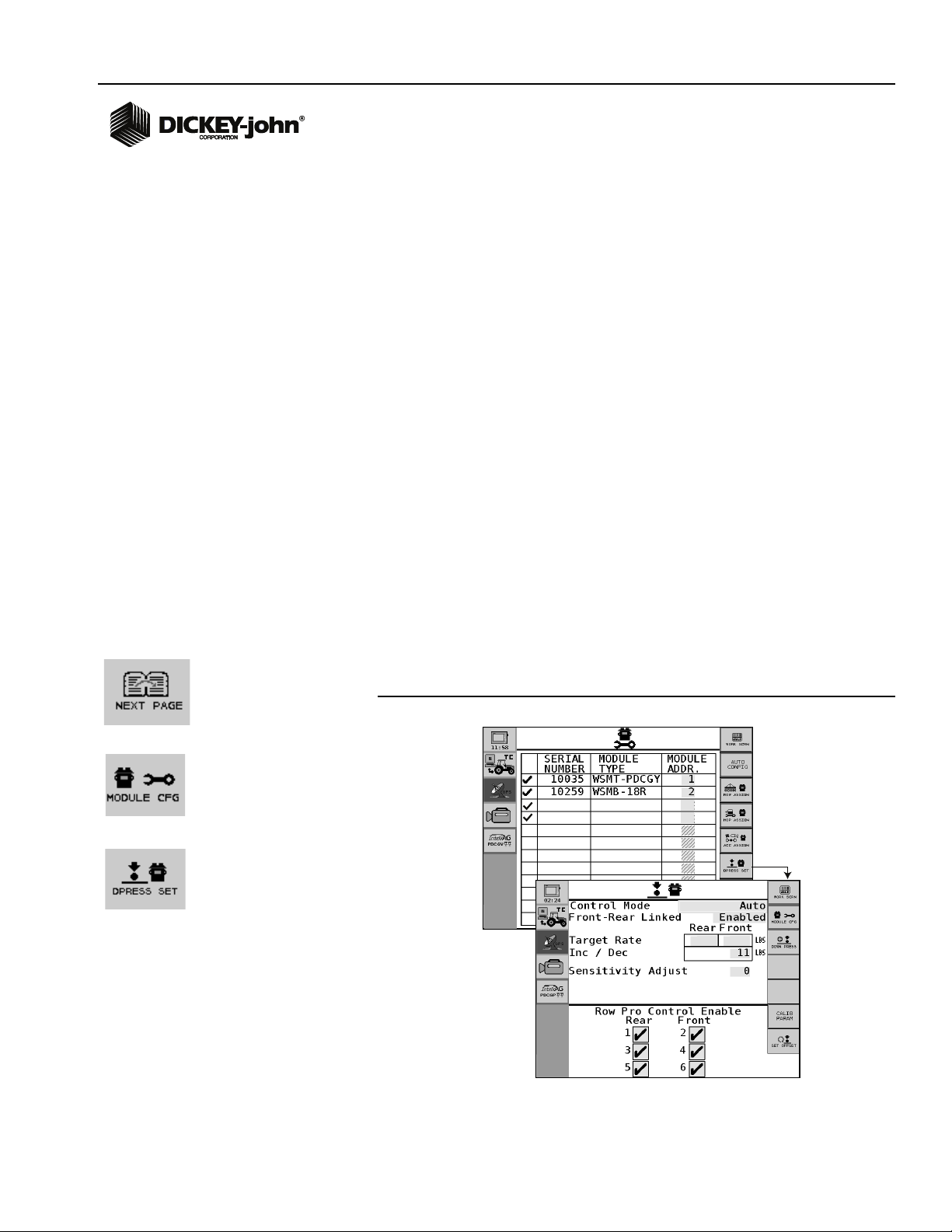
SETUP
Down Pressure setup is configured at the Module Configuration screen.
1. At the Main Work screen, press the Next Page button.
2. Press the Module Cfg button.
3. At the Module Configuration screen, press the DPress Set button.
4. At the Down Pressure Set screen, enter desired constants.
Figure 1
Down Pressure Setup
Row-Pro Down Pressure Control
11001-1572-201008
ROW-PRO DOWN PRESSURE SETUP / 1
Page 4
OPERATOR’S MANUAL
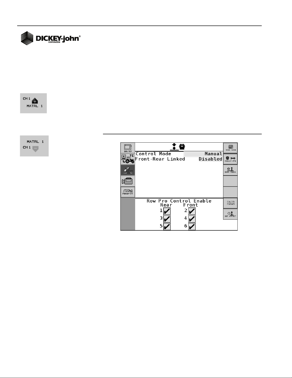
CONTROL MODE
Down pressure has two control modes:
• Automatic
• Manual
Automatic
When control mode is set to Automatic, down pressure adjusts
automatically during operation based on feedback sensor readings.
Manual
When control mode is set to Manual, down pressure operates at the set
pressure setting and will only change when pressure is adjusted by the
operator on the Main Work screen using the Increase/Decrease buttons.
Figure 2
Manual Control Mode
2 / ROW-PRO DOWN PRESSURE SETUP
Row-Pro Down Pressure Control
11001-1572-201008
Page 5
OPERATOR’S MANUAL
(1) linked
Increase/Decrease
adjustment for front
and rear
Front/Rear
Targets Linked
270
Increase
%
Decrease
%
Down Pressure force
applied relative
to target
0 . 0
150 150
150
130
150
130
FRONT- REAR LINKED
Enabled
Links the front and rear row units so that the same pressure increase/
decrease set at this screen is applied to front/rear row units. When enabled
only one increase/decrease value is entered.
Bar graph indicators on the Main Work screen identify the amount of force
applied in relation to the target set. In this mode, only one set of Increase/
Decrease buttons appear on the Main Work screen that will adjust the
percentage for both front and rear.
Figure 3
Front-Rear Linkage Enabled
Row-Pro Down Pressure Control
11001-1572-201008
ROW-PRO DOWN PRESSURE SETUP / 3
Page 6

OPERATOR’S MANUAL
(2) Increase/
Decrease
adjustments
for front
and rear
Down Pressure force
applied relative
to target
Increase
%
Decrease
%
Increase
%
Decrease
%
150
150
147 121
147
121
Disabled
The increase/decrease rate for front and rear row units is not linked and two
values must be entered at this screen. When disabled, two sets of
Increase/Decrease buttons appear on the Main Work screen that allows
adjustment of front and rear rates independently.
Figure 4
Front-Rear Linkage Disabled
4 / ROW-PRO DOWN PRESSURE SETUP
TARGET RATE
Target rate is the desired amount of down pressure (lbs). The system will
monitor and adjust pressure to meet the defined rate set at this screen.
INCREASE/DECREASE RATE
The increase/decrease rate establishes a set amount of pressure change
for each increase/decrease. This value is applied to the target rate while on
the Main Work screen. Refer to Front-Rear Linked description for linking
front/rear row units.
Row-Pro Down Pressure Control
11001-1572-201008
Page 7

OPERATOR’S MANUAL
1 and 2
Row Modules
Disabled
150 150
142
123
SENSITIVITY ADJUST
Sensitivity Adjust sets the response time of the control channel. Increasing
the adjustment above zero provides a quicker response time; decreasing
the adjustment to a negative number provides a slower response time.
Use caution when selecting a sensitivity adjustment. A rate set too
high could potentially cause equipment damage.
DISABLE DOWN PRESSURE MODULES
Modules interfacing with feedback sensors can be independently disabled
so that down pressure from disabled sensors do not display or are used in
adjustment calculations. Modules disabled are ignored by the system and
will not report down pressure data or react to soil conditions.
Figure 5
Down Pressure Modules
Row-Pro Down Pressure Control
11001-1572-201008
ROW-PRO DOWN PRESSURE SETUP / 5
Page 8

OPERATOR’S MANUAL
When planter is lifted,
OK button appears
to reset values.
112
106
128
120
115 111
RESET OFFSET VALUE
Resetting Offset Values clears previous down pressure readings and resets
values to zero.
Reset Offset Values:
1. At the Main Work screen, press the Next Page button.
2. Press the Module Cfg button.
3. At the Module Configuration screen, press the Dpress Set button.
4. At the Down Pressure Setting screen, press the OK button to clear
values.
IMPORTANT: The implement must be lifted and the implement lift
switch in the up state before the OK button appears and
values can be cleared.
Figure 6
Reset Offset Values
NOTE: Verify that side depth wheels
are not stuck in a position to
leave a residual pressure on
the load cell.
6 / ROW-PRO DOWN PRESSURE SETUP
Row-Pro Down Pressure Control
11001-1572-201008
Page 9

OPERATOR’S MANUAL
Select
Down
Pressure
ENABLE DOWN PRESSURE ON WORK SCREEN
To view down pressure functionality on the Main Work screen, the Down
Pressure data item must be selected on the Work Configuration screen.
To select Down Pressure:
1. At the Main Work screen, press the Next Page button and select the
Screen Config button.
2. Press a highlighted box and scroll through Data Items until Down
Pressure Scan appears.
3. Press the Checkmark button to select.
4. Press the Work Screen button to return to the Main Work screen.
Figure 7
Work Screen Configuration
DOWN PRESSURE DIAGNOSTICS
The Down Pressure Diagnostics screen is informational only and used for
troubleshooting purposes.
Screen displays:
• Load cell voltage/weight of 6 inputs
• Rear/front average
• Bar graphs displaying real-time monitoring of 6 inputs
To view Down Pressure Diagnostics:
1. At the Main Work screen, press the Module Cfg button.
2. At the Module Configuration screen, press the DPress Set button.
3. At the Down Pressure Setting screen, press the Down Press button.
Row-Pro Down Pressure Control
11001-1572-201008
ROW-PRO DOWN PRESSURE SETUP / 7
Page 10

OPERATOR’S MANUAL
158
144
144
139
126
135
151
146
Figure 8
Down Pressure Diagnostics Screen
8 / ROW-PRO DOWN PRESSURE SETUP
Row-Pro Down Pressure Control
11001-1572-201008
Page 11

OPERATOR’S MANUAL
40.5
Down
Pressure
147 147
1
2
3
127
111
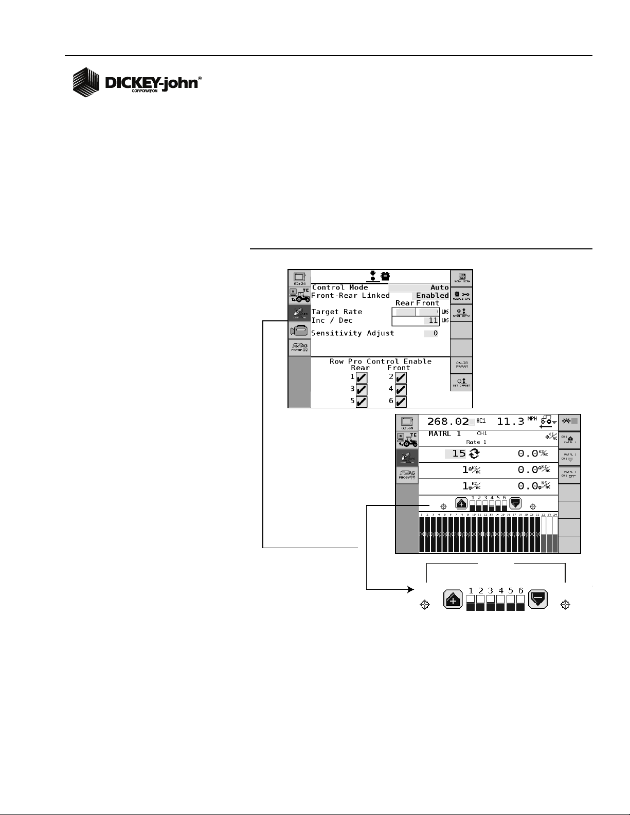
OPERATION
Constants defined at the Down Pressure Setup screen will monitor and
control down pressure and display on the Main Work screen when the
master switch is turned ON.
NOTE: Row-Pro Down Pressure is a
limited automatic adjustment
that works in conjunction
with the down pressure
springs. It does not
independently control the full
range of down pressure .
The Down Pressure data item has to be selected in the Work Screen
Configuration before appearing on the Main Work screen. Refer to Viewing
Down Pressure on Work Screen.
Figure 9
Main Work Screen with Down Pressure Enabled
1) Press the increase (+) button on the Main Work screen to increase the
target rate. The rate will change based on the increase setting defined at
the Setup screen.
2) Press the decrease (-) button on the Main Work screen to decrease the
target rate. The rate will change based on the decrease setting defined at
the Setup screen.
3) Down pressure bar graph indicators display the amount of force being
applied relative to the target rate defined at the Setup screen. Number of
bar graphs shown is based on the number of modules installed and inputs
enabled.
Row-Pro Down Pressure Control
11001-1572-201008
Figure 10
Down Pressure
OPERATION / 9
Page 12

OPERATOR’S MANUAL
10 / OPERATION
Row-Pro Down Pressure Control
11001-1572-201008
Page 13

OPERATOR’S MANUAL
TROUBLESHOOTING
Alarms will display on the Virtual Terminal with an audible alarm. The alarm
can be silenced by pressing the Alarm Cancel or ESC button. Detailed
descriptions of the alarm can be viewed by pressing the Alarm Detail
button. Some alarm conditions display instructions to aid in troubleshooting
the situation. Each alarm type has an associated alarm number for
reference.
DOWN PRESSURE UNABLE TO CONTROL
Alarm 265
The system is unable to monitor or control down pressure. Full screen
alarm identifies the module unable to control.
Corrective Action
• Check for sufficient tank pressure.
• Check load cell sensor for damage.
• Check air valve for damage.
• Inspect module and module harness for damage.
• Verify constants entered at the Down Pressure Setup screen are
correct.
Figure 11
Down Pressure Unable to Control Alarm
Contact DICKEY-john Technical Support Group at 1-800-637-3302 for
troubleshooting assistance or questions.
Row-Pro Down Pressure Control
11001-1572-201008
TROUBLESHOOTING / 11
Page 14

OPERATOR’S MANUAL
12 / TROUBLESHOOTING
Row-Pro Down Pressure Control
11001-1572-201008
Page 15

Dealers have the responsibility of calling to the attention of their customers the following
warranty prior to acceptance of an order from their customer for any DICKEY-john product.
DICKEY-john® WARRANTY
DICKEY-john warrants to the original purchaser for use that, if any part of the product
proves to be defective in material or workmanship within one year from date of original
installation, and is returned to DICKEY-john within 30 days after such defect is discovered,
DICKEY-john will (at our option) either replace or repair said part. This warranty does not apply
to damage resulting from misuse, neglect, accident, or improper installation or maintenance; any
expenses or liability for repairs made by outside parties without DICKEY-john’s written consent;
damage to any associated equipment; or lost profits or special damages. Said part will not be
considered defective if it substantially fulfills the performance expectations. THE FOREGOING
WARRANTY IS EXCLUSIVE AND IN LIEU OF ALL OTHER WARRANTIES OF
MERCHANTABILITY, FITNESS FOR PURPOSE, AND OF ANY OTHER TYPE, WHETHER
EXPRESS OR IMPLIED. DICKEY-john neither assumes nor authorizes anyone to assume for it
any other obligation or liability in connection with said part and will not be liable for
consequential damages. Purchaser accepts these terms and warranty limitations unless the
product is returned within fifteen days for full refund of purchase price.
For DICKEY- john Service Department, call
1-800-637-3302 in either the U.S.A. or Canada
Headquarters:
5200 Dickey-john Road, Auburn, IL USA 62615
TEL: 217 438 3371, FAX: 217 438 6012, WEB: www.dickey-john.com
Europe:
DICKEY-john Europe S.A.S, 165, boulevard de Valmy, 92706 – Colombes – France
TEL: 33 (0) 1 41 19 21 80, FAX: 33 (0) 1 47 86 00 07 WEB: www.dickey-john.eu
Copyright 2009 DICKEY-john Corporation
Specifications subject to change without notice.
 Loading...