

Page 1

OPERATOR’S MANUAL
Safety Notices ..................................................................................................... 1
Introduction ......................................................................................................... 3
Auto Section Control Features .......................................................................................... 3
Requirements ....................................................................................................................3
Auto Section Control Installation ....................................................................................... 4
Cab Terminal Mount ......................................................................................................................... 4
Harness Connections ........................................................................................................ 5
Auto Section Terminal ........................................................................................ 7
Auto Section Power Up ..................................................................................................... 9
Understanding the Field Map ............................................................................................ 9
Path-Driven Outline .......................................................................................................................... 9
Imported External Boundary .......................................................................................................... 10
Tractor/Implement Position ............................ ... .. ................................ .. ... ... ................................... 11
Intelliag PDC Setup ........................................................................................... 13
Implement Setup .......................................................................... .... ... ... ... .... ... ............... 13
Physical Layout ............................................................................................................... 14
3 Point Hitch and Towed Hitch ....................................................................................................... 15
Rigid Cart Mount ............................................................................................................................ 16
Tow-Behind Cart ............................................................................................................................ 16
Physical Check ............................................................................................................... 17
Clutch Configuration ....................................................................................................... 18
Multiple Tru Count Output Module Assignment ............................................. ................................ 18
Tru Count Output Module Assignment ................ ... .. ................................ ... .. ... .............................. 18
Assigning Rows .............................................................................................................................. 19
Assigning Row Shutoff Switches .................................................................................................... 20
Module Output Assignment Example .................. ... .. ................................ ... .. ... .. ... ......................... 21
Implement Section Check .............................................................................................................. 21
Auto Section Control Setup ............................................................................. 23
GPS Setup ...................................................................................................................... 23
GPS Source ................................................................................................................................... 23
GPS Lag ......................................................................................................................................... 23
Baud Rate and Data Mode (RS232 only) ....................................................................................... 23
GPS Output .................................................................................................................................... 23
Tractor Setup (Articulated) ................................ .. ... .. ................................ ... .. ... .............................. 25
GPS Calibration .............................................................................................................. 26
Important GPS Calibration Notes ............................................. ... .. ... ................................ .. ... .. ....... 27
Field Preparation ............................................................................................... 29
Setting Overlap ...................................... ... ... ... .... ... ... ... .... ...................................... ... .... .. 29
Run In Overlap ............................................................................................................................... 29
Run Out Overlap ............................................................................................................................ 29
Run In Skip ..................................................................................................................................... 29
Run Out Skip .................................................................................................................................. 29
Side-to-Side Overlap ......................... .. ... ... ............................... ... .. ................................ ... .. ............ 29
Important Functionality Notes ........................................................................................................ 31
Create Task .................................................................................................................................... 33
Import A Task or Field Boundary File ............................................................................. 34
Overwrite Field Boundary ............................................................................................................... 36
Auto Section Control Status ........................................................................................................... 36
Auto Section Control System
11001-1561B-201207
/I
Page 2

OPERATOR’S MANUAL
System Operation ............................................................................................. 37
Auto Section Main Screen .............................................................................................. 37
Enable Auto Section Control .................................... .... ... ... ....................................... ... .. 39
Disable Auto Section Control .......................................................................................... 39
Auto Mode ............................. ....................................... ... ... ... .... ... ... ... ... .... ..................... 40
Manually Force Sections Off in Auto .............................................................................................. 40
Manual Mode .................................................................................................................. 41
Manual On/Off Control of Sections ................................................................................................. 41
Additional Operating Conditions ......................................................... ... .... ... ... ... .... ........ 42
Adjusting Implement Position ......................... ... ................................ .. ... .. ...................................... 42
Marking/Planting Headlands ........................................................................................................... 42
Storing Headlands .................................... ...................................................................................... 43
Lost GPS Signal ............................................................................................................. 43
Out of Field Range ......................................................................................................... 44
Terminal Storage Capacity .............................................................................. 45
Clear Task ......................................................................................................................45
Diagnostics ....................................................................................................... 47
GPS Status ..................................................................................................................... 47
System Information .......................................... ... ... ... .... ... ... ... ....................................... .. 48
Clutch Section Check ..................................... ................................ ... .. ... ........................................ 49
Troubleshooting ............................................................................................... 51
Error Codes ....................................................................................................... 55
Appendix A ............................................... .... .... .... ..... .... .... .... .... ..... .... .... .... .... .. 56
AGCO GTA Console ...................................................................................................................... 56
Appendix B ............................................... .... .... .... ..... .... .... .... .... ..... .... .... .... .... .. 57
John Deere GS2 Console ............................................................................................................... 57
Deere GS2 Console Cab Harness Connecti on s .................................... .. ................................ ... .. . 58
Warranty.............................................................................................................. 63
II /
Auto Section Control System
11001-1561B-201207
Page 3
OPERATOR’S MANUAL
SAFETY NOTICES
Safety notices are one of the primary ways to call attention to potential
hazards. An absence of specific alerts does not mean that there are no
safety risks involved.
This Safety Alert Symbol identifies important safety
messages in this manual. When you see this symbol,
carefully read the message that follows. Be alert to
the possibility of personal injury or death.
Use of the word WARNING indicates a potentially hazardous
situation which, if not avoided, could result in death or serious
injury.
Use of the word CAUTION with the Safety Alert Symbol indicates a
potentially hazardous situation which, if not avoid ed, may result in
minor or moderate injury.
Use of the word CAUTION without the safety alert symbol
indicates a potentially hazardous situatio n which, if not avoided,
may result in equipment damage.
Auto Section Control System
11001-1561B-201207
SAFETY NOTICES / 1
Page 4

OPERATOR’S MANUAL
2 / SAFETY NOTICES
Auto Section Control System
11001-1561B-201207
Page 5
OPERATOR’S MANUAL
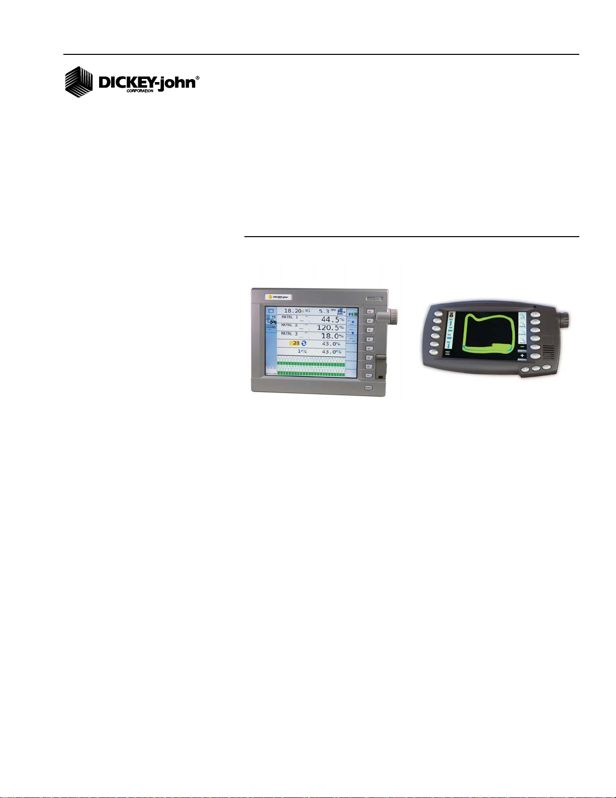
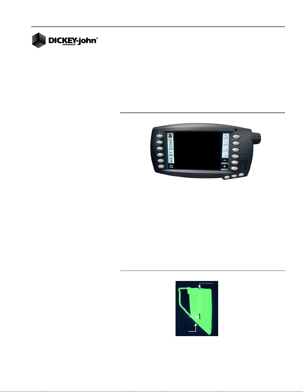
Auto Section Control
Terminal
IntelliAg
Virtual Terminal
INTRODUCTION
Auto Section Control is an automated row shutoff system that can be added
to the IntelliAg planter system to automatically shutoff individual planter
sections utilizing a GPS signal as previously planted areas are approached.
A dedicated Auto Section Control terminal displays a field map for easy
identification of external field boundaries, seeded areas, and nonseeded
areas.
Figure 1
Auto Section Control Terminal and IntelliAg Virtual Terminal
AUTO SECTION CONTROL FEATURES
• Real-time viewing of planting operation within the field without
interruption of application rate and seed monitoring information
• Unique GPS latency adjustment for calibration of row shutoff at the
precise time the planter enters a previously seeded area
• Manual override of planter sections in the event of a lost GPS signal or
in special conditions
• Section(s) shutoff and turn on when exiting or entering a headland
• Day and night mode
• Saving field data by customer, farm, field, and task structure for
viewing at a later date
REQUIREMENTS
The Auto Section Control system will only interface and operate with an
IntelliAg Planter Control system and compatible virtual terminal.
The Auto Section Control system requires the following to operate:
• Compatible with IntelliAg A1+ virtual terminal, John Deere GS2 2600
display, or AGCO C2000 virtual terminal
• Auto Section Control terminal
• GPS receiver (5 Hz minimum)
• Tru Count WSMB module
• Tru Count WSMB harness
• Implement lift switch
• Row section control switch box
Auto Section Control System
11001-1561B-201207
INTRODUCTION / 3
Page 6
OPERATOR’S MANUAL
Secure VT to bracket using
4 Metric screws (included)
Secure bracket to
tractor cab using 4
SAE screws (included)
1
2
3
4
AUTO SECTION CONTROL INSTALLATION
The Auto Section Control cab kit includes:
• Swath Control display
• Display mount
• Display to CAN harness
Refer to (Figure 3) harness connections.
CAB TERMINAL MOUNT
The Auto Section Control terminal is secured in the tractor cab by a ram
mount bracket.
• Ball mount at top and bottom of bracket allows for orientation in many
different positions.
• Wing bolt in middle of bracket tightens and secures the terminal to the
desired position.
Figure 2
Auto Section Control Terminal Mount
4 / INTRODUCTION
Position terminal so that operator view is not obstructed and does
not interfere with tractor operation.
Auto Section Control System
11001-1561B-201207
Page 7

OPERATOR’S MANUAL
Auto Section
Control Terminal
ISO
Tractor
Hitch
WSMT 2 ‘T’ Harness
467980850
Add a CAN Extension
or
CAN Terminator
WSMB
Tru Count
Output Module
Tru Count
Solenoid
Modules
(available from
Tru Count)
Tru Count
Clutch Harness
467983505
IntelliAg
Virtual Terminal
Hitch Extension
Harness
46798013x
Battery
Tractor
Power
Harness
467980455
CFM Switch
Module or
Row Control
Switch Module
467984264S1
WSMT 2
PDC Module
Tractor ECU
Master
Switch
Radar
RS232 (not
used with
Auto Section
Control)
Tractor A1
Harness
467980451A
RSM/CFM to
CAN Harness
467980330
Auto
Section
Terminal
Interface
Harness
467980458
GPS Receiver
(See Note)
Ignition
NOTE: GPS receiver connects
direct to RS232 on Auto Section
Terminal harness. Refer to
Auto Section Control Setup to
transmit GPS signal over CAN.
HARNESS CONNECTIONS
The Auto Section Control terminal connects to the IntelliAg tractor harness
for communication with the IntelliAg ISO virtual terminal. A GPS receiver is
required to provide implement position via CAN or RS232 communication.
A row control switch module/clutch folding switch module provides quick
access of turning sections on and off when manual override is required.
Ignition wire connects to switched power source.
NOTE: Refer to Appendix A and B for
harness connections when
using an AGCO or John Deere
Console.
Figure 3
Harness Connections
A DICKEY-john Tru Count output module WSMB and harness are required
for interfacing with Tru Count solenoid modules. Tru Count solenoid
modules are not supplied by DICKEY-john. The below items outlined
indicate parts required for Auto Section Control functionality.
Auto Section Control System
11001-1561B-201207
:
INTRODUCTION / 5
Page 8

OPERATOR’S MANUAL
6 / INTRODUCTION
Auto Section Control System
11001-1561B-201207
Page 9

OPERATOR’S MANUAL
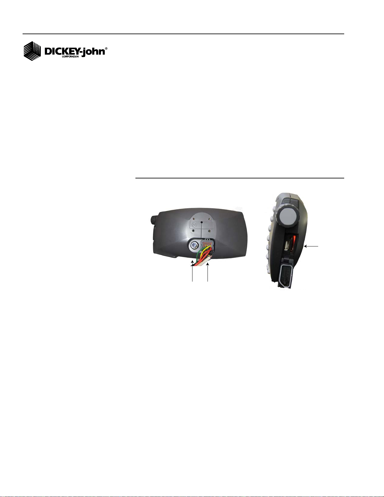
1
2
3
4
5
6
7
8
9
10
11
12
13 14 15
16
Day Mode Night Mode
AUTO SECTION TERMINAL
The Auto Section Control terminal displays the field coverage map that
shows real-time viewing of the planting operation and indicates the vehicle’s
current location.
NOTE: All Auto Section Control setup
is entered on the IntelliAg
virtual terminal or other
compatible displays.
• Field map appearance on the screen is adjusted using the buttons
located on the left and right side of the terminal (Figure 4).
Figure 4
Auto Section Control Terminal Functions
(1) Tractor - Returns to current field position after using the Pan buttons and
centers the tractor to screen middle
(2 - 5) Pan - Positions field map on screen to the left, right, up, or down
(6) - Night Mode/Day Mode - Adjusts screen colors for operating at night or
during the day
Figure 5
Day and Night Mode
(7) - Max In - Enlarges map to the most detailed view
(8) - Zoom In - Enlarges field map with each button press
Auto Section Control System
11001-1561B-201207
(9) - Zoom Out - Reduces field map with each button press
(10) - Max Out - Shows entire field
(11) Increases screen brightness
AUTO SECTION TERMINAL / 7
Page 10
OPERATOR’S MANUAL
17 18
19
(12) Decreases screen brightness
(13) Terminal - non functional
(14) Cycle button - Adjusts the implement to its actual heading (North,
South, East, West direction) if the initial tractor movement is reverse, such
as backing to a corner. The Flip button also performs the same function.
(15) Terminal - non functional
(16) Rotary button - non operational
(17) Video connection - non functional
(18) Terminal harness connection
(19) SD card slot - import task data files
USB port - terminal software reprogramming
Figure 6
Auto Section Control Terminal Side and Back View
8 / AUTO SECTION TERMINAL
Auto Section Control System
11001-1561B-201207
Page 11
OPERATOR’S MANUAL
Auto
Initializing....
Please Wait
1 Path-driven field outline
2 Seeded area
3 Nonseeded area
4 Over applied area
1
2
3
4
AUTO SECTION POWER UP
The terminal automatically powers on and off when the ignition switch is
powered on and off. At startup, the screen will indicate that the system is
initializing until a connection is made with GPS and the IntelliAg PDC
controller.
When the power is turned off, an orange LED appears in the upper right
corner for approximately 1 minute while data is saving and disappears after
completing the save.
Figure 7
Initializing
UNDERSTANDING THE FIELD MAP
The Auto Section Control Terminal displays field coverage maps for
real-time viewing of the planting operation without interruption of application
rate and seed monitoring information. The full-color display identifies
path-driven outlines, external boundaries, areas planted, and areas left to
plant.
PATH-DRIVEN OUTLINE
The outline of a field can be driven to use as a visual aid when planting.
This is not considered an external boundary so automatic row shutoff will
not occur when driving past the outline.
Figure 8
Path-Driven Field Outline Map
Auto Section Control System
11001-1561B-201207
AUTO SECTION TERMINAL / 9
Page 12
OPERATOR’S MANUAL
Internal
Boundary
Field
(yellow)
Seeded
Area
(green)
External
boundary
(gray)
Field Map Descriptions:
(1) Path-driven field outline - Driving an external field path provides a visual
outline of the field. Automatic row shutoff does NOT occur when a section
extends past the outline.
(2) Seeded area - Areas planted with seed is defined in green.
(3) Nonseeded area - Any areas not seeded remain in yellow or brown
(4) Over applied area - Areas with twice applied seed appears in blue
IMPORTED EXTERNAL BOUNDARY
Field maps created in a PC farm software that is compatible with the
IntelliAg Task Control application can be imported to the Auto Section
Control terminal. Automatic row shutoff occurs when any defined external
and internal boundaries are entered.
(1) External boundary - Any defined boundary outside of the field appears in
gray (day mode) or black (night mode). Rows automatically shut off if a
section extends past the external boundary.
(2) Internal boundary - Any defined boundary within the field appears in
gray (day mode) or black (night mode). Rows automatically shut off if a
section extends into the internal field boundary.
(2) Seeded area - Areas planted with seed are defined in green.
(3) Nonseeded area - Any areas not seeded remain in yellow (day mode) or
brown (night mode).
(4) Over applied area - Areas with multiple applications appears in blue.
Figure 9
External / Internal Boundary
10 / AUTO SECTION TERMINAL
Auto Section Control System
11001-1561B-201207
Page 13
OPERATOR’S MANUAL
Implement
Tractor
Direction
Indicator
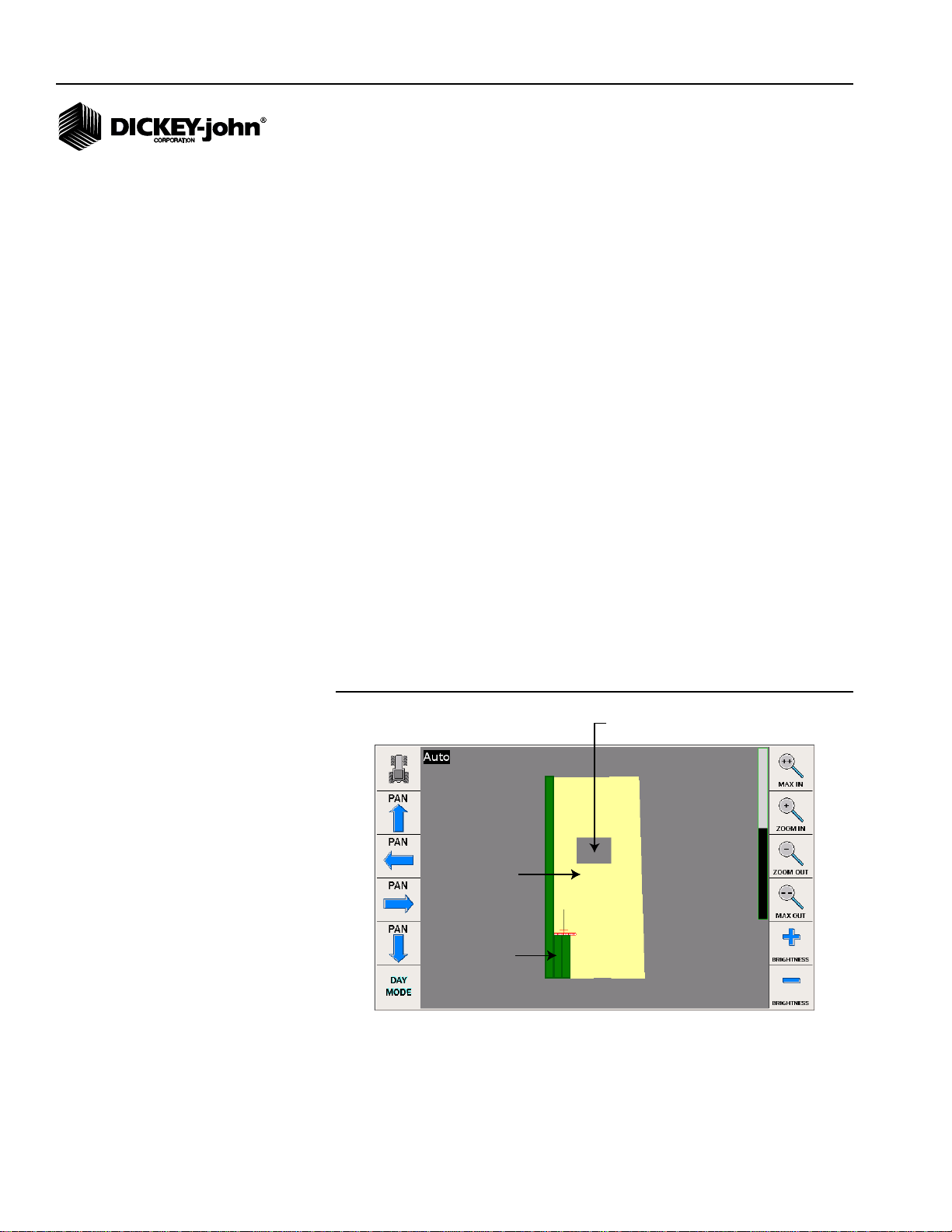
TRACTOR/IMPLEMENT POSITION
A direction indicator identifies the front of the tractor and direction the tractor
is heading.
Figure 10
Tractor Position
Auto Section Control System
11001-1561B-201207
AUTO SECTION TERMINAL / 11
Page 14

OPERATOR’S MANUAL
12 / AUTO SECTION TERMINAL
Auto Section Control System
11001-1561B-201207
Page 15
OPERATOR’S MANUAL
INTELLIAG PDC SETUP
The following IntelliAg PDC screens must be configured to communicate
with the Auto Section Control application/terminal and perform Auto Section
Control functions.
• Implement Layout
• Planter Output Module
• Clutch Module/Switch Assignment
IMPORTANT: Rows must be assigned to a channel before proceeding
to implement setup. Row assignment can be verified at
the Channel Setup screen.
NOTE: If using the IntelliAg system
prior to Auto Section Control,
some of the IntelliAg screens
may already be configured and
do not require additional setup.
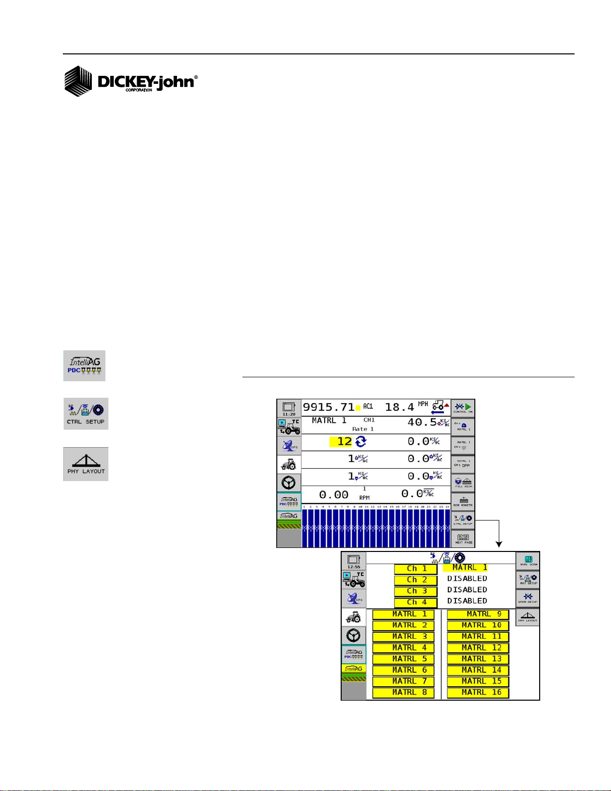
IMPLEMENT SETUP
To Enter Implement Settings:
1. Press the IntelliAg PDC button to display the IntelliAg Main Work
screen.
2. At the Main Work screen, press the Control Setup button.
3. At the Control Setup screen, press the Physical Layout button.
Figure 11
Physical Setup Screen
Auto Section Control System
11001-1561B-201207
INTELLIAG PDC SETUP / 13
Page 16
OPERATOR’S MANUAL
Implement
Center 0”
Y coordinate
-Y = center of channel 1 (rows 1-16) left of hitch
+Y= center of channel 2 (rows 17-32) right of hitch
-180
-Y
180
+Y
-X
-180
X coordinate
-X = distance from hitch to
implement center
Channel 1
Planter Ctrl
Rows 1-16
Channel 2
Planter Ctrl
Rows 17-32
Channel
Center
Implement
Center 0”
-0
-Y
+0
+Y
-X
-180
X coordinate
-X = distance from hitch to
implement center
Channel 1
Planter Ctrl
Rows 1-24
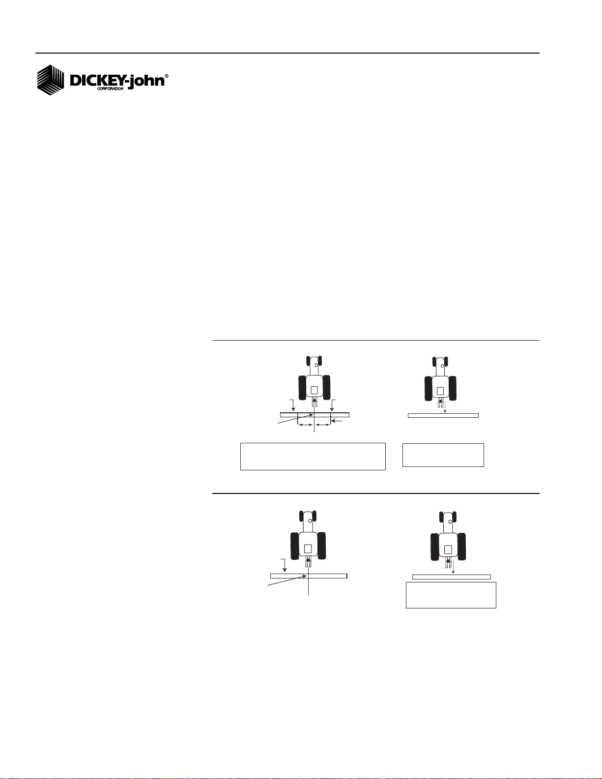
PHYSICAL LAYOUT
Physical layout of the implement is required to determine the position of the
planter control channel in the field. The physical layout of planter center is
calculated by measuring the distance from the center of the row units to the
hitch pivot point connection.
NOTE: If T ask Controller functionality is
used, these coordinates should
already be established.
To measure X/Y Coordinates:
1. Stand behind the implement facing tractor.
X coordinate:
– Measured from the hitch pivot point to where the seed is placed in
the ground, i.e. bottom of seed tube, and entered as a negative
entry (-X). This measurement should be entered for each control
channel enabled.
Y coordinate:
– Channels to the left of hitch pivot point are entered as a negative
entry (-Y).
– Channels to the right of hitch pivot point are entered as a positive
entry (Y).
Figure 12
32 Row Planter 2 Control Channels X /Y Coordinate Example
14 / INTELLIAG PDC SETUP
Figure 13
24 Row Planter 1 Control Channel X / Y Coordinate Example
IMPORTANT: It is critical to enter the exact distances required when
setting up the physical layout of the implement position.
Do not guess; use a tape measure to find exac t
measurements. Failure to enter accurate measurements
of the implement control channels will impa ct the
system’s performance to shut row sections off at the
proper location within the field.
Auto Section Control System
11001-1561B-201207
Page 17
OPERATOR’S MANUAL
3-Point Hitch Towed Hitch Tow-Behind CartRigid-Cart Mount
Select
Implement
Type
Enter X Y Coordinates
for each enabled channel
A red button
indicates
GPS signal
is lost.
2. At the Physical Layout screen, select the appropriate implement layout
type by pressing the tractor/implement graphic.
Figure 14
Implement Layout Types
3. Enter in the table each channel’s X and Y coordinates. X and Y
coordinate measurements will vary based on the implement type
selected.
NOTE: When operating with only 1
control channel, the “Y” value
on the Physical Layout screen
should remain at 0 unless the
implement is offset left or right
of center.
NOTE: Use the gray implement table
on screen as a guide to verify
channels are aligned correctly
as X Y coordinates are entered.
IMPORTANT: If there are no rows assigned to a control channel, such
as operating in Monitor Only mode, a row column
appears on the Physical Layout screen and rows must
be assigned an offset.
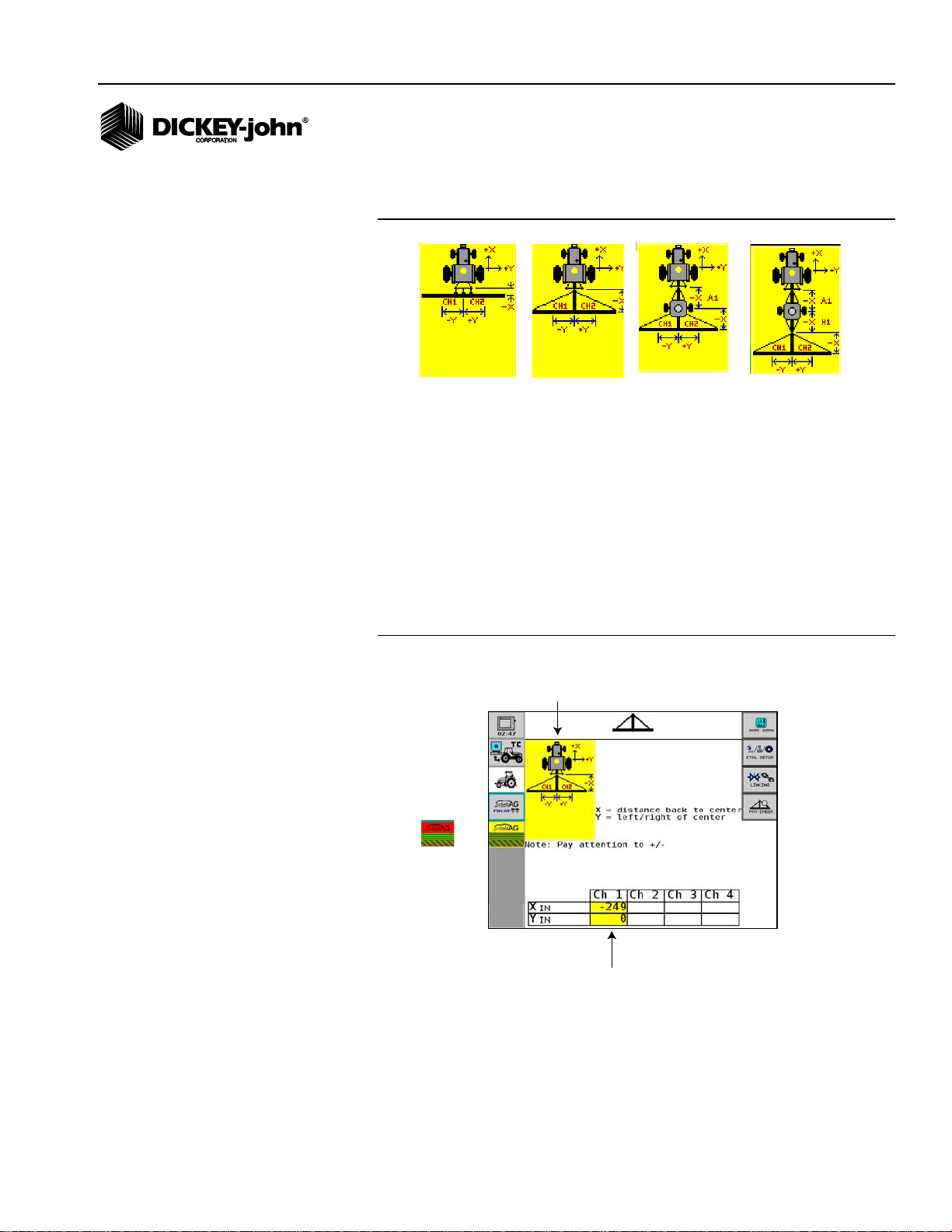
3 POINT HITCH AND TOWED HITCH
Figure 15
Physical Layout Screen - 1 Channel Assignment (3 Point Hitch and Towed Hitch)
Auto Section Control System
11001-1561B-201207
INTELLIAG PDC SETUP / 15
Page 18
OPERATOR’S MANUAL
-180
Hitch to cart
axle
measurement
- 40
- 40
Control channel
over lap (Y coordinates
are not correct)
Implement
Table appears indicating
channel assignment as
X Y coordinates
are entered for two or
more channels
Correct control
channel alignment
(Y coordinates
entered correct)
-180
-180
Hitch to Cart
Axle
Measurement
Cart Axle to
Implement
Hitch
Measurement
RIGID CART MOUNT
An additional -X coordinate measurement from hitch to cart axle is entered
in (A1) table.
Figure 16
Physical Layout Screen - 2 Channel Assignment (Rigid Cart Mount)
NOTE: When operating with only 1
control channel, the “Y” value
on the Physical Layout screen
should remain at 0.
16 / INTELLIAG PDC SETUP
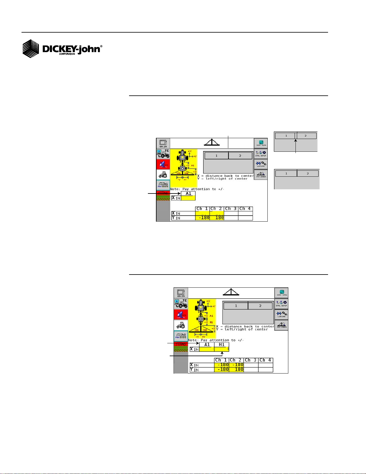
TOW-BEHIND CART
Two additional -X and -Y coordinate measurements from hitch to cart axle
entered in (A1) and cart center to implement hitch (H1).
Figure 17
Physical Layout Screen (Tow-Behind Cart)
4. To view implement layout, press the Physical Check button.
Auto Section Control System
11001-1561B-201207
Page 19
OPERATOR’S MANUAL
Channel 1 center
(1)
(2)
(3)
OVERLAP
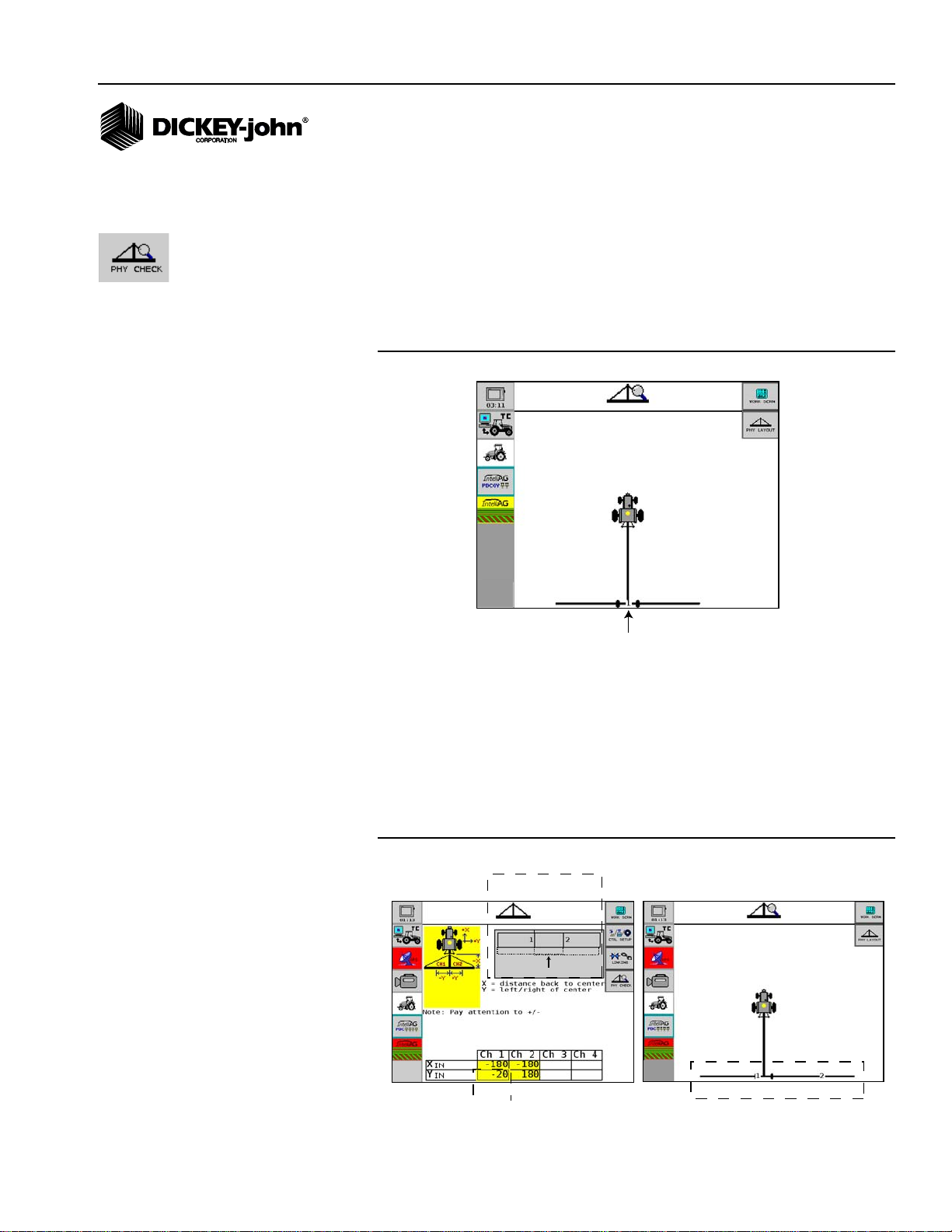
PHYSICAL CHECK
The Physical Check screen visually displays the implement layout and
control channel center as entered on the Physical Layout screen. Use this
screen to verify channels are setup correctly.
To view Physical Check screen:
1. At the Physical Layout screen, press the Physical Check button.
(Figure 18) depicts channel 1 setup in a correct format.
Figure 18
Physical Check Screen Setup Correct (Example Only)
(Figure 19) depicts an incorrect Y channel setup:
1. Y coordinate for channel 1 entered incorrectly.
2. Control channel graphic (gray box) shows that channel 1 and 2 are not
aligned correctly and are overlapping.
3. Physical check screen provides another visual of actual control
channel center for channel 1 that is incorrectly aligned and overlapping
channel 2.
Figure 19
Physical Check Screen Setup Incorrect
Auto Section Control System
11001-1561B-201207
INTELLIAG PDC SETUP / 17
Page 20

OPERATOR’S MANUAL
CLUTCH CONFIGURATION
Clutch module configuration is required to:
• Identify how many planter output modules are connected to the
IntelliAg system
• Assign how many outputs are assigned to each output module
• Assign how many rows are assigned to each output
• Assign row shutoff module switches to outputs that enable and disable
planter sections
MULTIPLE TRU COUNT OUTPUT MODULE ASSIGNMENT
Output module addresses are a critical parameter used to identify a
module’s position on the implement that will control row shutoff switches.
IMPORT ANT: If a planter uses more than one output module, modules
MUST be installed in increasing serial number order
starting on the left side and proceeding to the right so
that row assignment is configured correctly.
TRU COUNT OUTPUT MODULE ASSIGNMENT
The Clutch Module Configuration screens displays:
• Module address
• Type
• Number of outputs per module
To enter # of Outputs per Module:
1. At the IntelliAg Main Work screen, press the Module Configuration
button.
2. At the Module Configuration screen, press the Clutch Module button.
3. Enter the number of solenoid outputs connected to the specific TCOM.
Outputs do NOT always total the number of clutches but the total
number of controlled solenoids. The Output Numbers (#s) value is
automatically sequenced for each module based on the module
address value.
4. Enter the shutoff delay times for engaging and disengaging clutches.
Delay times vary based on manufacturer. Refer to (Figure 20) for
recommended clutch delay times.
Delay time defaults for both turning on and shutting off is set at 0.0 seconds
on the Clutch Configuration screen.
IMPORTANT: The shutoff delay time is a mechanical delay for
engaging and disengaging clutches. Seconds entered
at this screen will increase the look-ahead time when
shutting off and turning on rows controlled at the Auto
Section Control screens. Shutoff delay times can effect
accuracy of Run in and Run Out functionality.
18 / INTELLIAG PDC SETUP
Auto Section Control System
11001-1561B-201207
Page 21

OPERATOR’S MANUAL
Figure 20
Clutch Delay Times
Clutch Type Turn Off Turn On
TruCount 0.4 seconds 0.4 seconds
Great Plains 0.3 seconds 0.4 seconds
Contact DICKEY-john Technical Support at 1-800-637-3302 for
recommended shutoff delay times on all other clutches.
Figure 21
Clutch Configuration Screen
ASSIGNING ROWS
The Clutch Configuration screen assigns rows to outputs. As rows are
assigned to each output, row numbers automatically populate.
1. At the Clutch Module screen, press the Clutch Configuration button.
Enter number of rows to be assigned to each output.
Figure 22
Clutch Configuration
Auto Section Control System
11001-1561B-201207
INTELLIAG PDC SETUP / 19
Page 22

OPERATOR’S MANUAL
A red button
indicates
GPS signal
is lost.
ASSIGNING ROW SHUTOFF SWITCHES
The Clutch Set screen identifies what switches on the row shutoff switch
box enable and disable planter sections or outputs.
1. At the Clutch Configuration screen, press the Clutch Set button. Enter
which clutch switch will be assigned to an output module to enable and
disable planter sections.
Figure 23
Clutch Set Screen
20 / INTELLIAG PDC SETUP
Auto Section Control System
11001-1561B-201207
Page 23

OPERATOR’S MANUAL
MASTER
ROW SECTION
123
4
5
6
Rows
1-9
Rows
10-15
Rows
16-24
Master
On/Off
Not
assigned
Not
assigned
Not
assigned
1
2
3
4
TCOM
MODULE OUTPUT ASSIGNMENT EXAMPLE
1. Three solenoid outputs to be controlled by Tru Count output module.
2. Number of rows assigned to each output.
3. Row shutoff switches assigned to corresponding outputs.
4. Corresponding row shutoff switches will turn sections on and off.
Figure 24
Clutch Setup for Row Shutoff Module
Auto Section Control System
11001-1561B-201207
IMPLEMENT SECTION CHECK
IMPORTANT: After clutch row assignment, it is recommended to
perform a diagnostics check to verify the order of clutch
sections shut on and off correctly. Refer to the
Diagnostics section for section check instruction.
INTELLIAG PDC SETUP / 21
Page 24

OPERATOR’S MANUAL
22 / INTELLIAG PDC SETUP
Auto Section Control System
11001-1561B-201207
Page 25

OPERATOR’S MANUAL
AUTO SECTION CONTROL SETUP
Auto Section Control setup is entered on the IntelliAg virtual terminal. The
following Auto Section Control screens must be configured to perform Auto
Section Control functions.
• GPS Setup/Calibration
• System Setup
• Selecting a Task
GPS SETUP
GPS setup and calibration is required for the system to know implement
position in relation to the GPS receiver mounting location on the tractor and
effectively operate Auto Section control.
IMPORTANT: A minimum 5 Hz GPS receiver is required for
communication with the Auto Section Control system.
Any receiver less than 5 Hz will not provide adequate
communication to run the Auto Section Control system.
GPS SOURCE
The Auto Section Control system communicates with the GPS receiver
using either:
• CAN (GPS receiver signal broadcast over CAN)
• RS232 (GPS receiver connected to RS232 port)
If using an RS232 GPS source, the receiver must be connected to the Auto
Section Control terminal to prevent any additional system communication
delays.
GPS LAG
GPS lag time is the amount of delayed communication time in seconds that
occurs between the Auto Section Control system and the GPS receiver. A
GPS calibration is required to define the GPS lag time.
BAUD RATE AND DATA MODE (RS232 ONLY)
Baud Rate and Data Mode are communication signals as defined by the
manufacturer of the GPS receiver. Reference the receiver manual for
settings.
GPS OUTPUT
The GPS Output setting converts an RS232 output to CAN in a NMEA 2000
format and should be enabled when the following conditions occur:
Auto Section Control System
11001-1561B-201207
• Using an RS232 receiver and
• Using Task Controller functionality
The default setting is disabled.
AUTO SECTION CONTROL SETUP / 23
Page 26

OPERATOR’S MANUAL
TRACTOR SETUP (FIXED)
To determine an accurate reference point between the GPS receiver and
Auto Section Control, three distance positions are required:
• Distance from the GPS receiver antenna mounting location to the rear
axle center
• Distance from rear axle center to the implement hitch
• Distance from GPS receiver antenna mounting location to implement
hitch center of tractor
To enter GPS Setup:
1. At the Auto Section Control screen, press the System Setup button.
2. At the System Setup screen, press the GPS Setup button.
3. Select the GPS Source as RS232 or CAN.
4. Enter GPS lag time only after a calibration is performed. Refer to the
GPS Calibration section to perform test.
5. Select the Baud Rate and Data Mode if RS232 is the GPS source for
the GPS receiver. Reference the GPS receiver manual for settings.
6. If RS232, check the GPS Output input box to enable GPS messages in
NEMA 2000 format. This allows a GPS signal to be communicated
over CAN and available for use by the IntelliAg virtual terminal or Task
Controller.
7. Select Tractor Setup as Fixed.
8. Enter receiver/implement distances per below.
To determine Receiver/Implement Position (Fixed):
IMPORTANT: It is critical to enter the exact distances required when
setting up the receiver/implement position. Do not
guess; use a tape measure to find exact measurements.
Failure to enter accurate receiver and implement
positions will impact the system’s performance to shut
row sections off at the proper location with the field.
9. Place the tractor on a flat, level surface. Tractor should be straight for
accurate measurement.
10. Measure the horizontal (side-to-side) distance between the receiver
and implement hitch center. If the receiver is mounted in the center, the
value is 0. Enter the value in inches into the Receiver to Center input
box.
–Use the Left/Right button to position the blue receiver indicator to
visually represent if the antenna is located on the left or right side of
the tractor.
11. Measure the distance from the center of the receiver to the center of
the fixed axle. Enter the value in inches into the Receiver to Axle input
box.
12. Measure the distance from the center of the rear axle to the implement
hitch pin pivot point for pull-type implements. Enter the value in inches
into the Axle to Hitch input box.
24 / AUTO SECTION CONTROL SETUP
Auto Section Control System
11001-1561B-201207
Page 27

OPERATOR’S MANUAL
0.5
8
42
Figure 25
GPS Setup Screen
TRACTOR SETUP (ARTICULATED)
NOTE: Measurements entered as
inches/meters.
To determine an accurate reference point between the GPS receiver and
Auto Section Control, four distance positions are required:
• Distance from the GPS receiver antenna to the front axle center
position
• Distance from front axle center to pivot point
• Distance from pivot point to rear axle center
• Distance from rear axle center to implement hitch
To enter GPS Setup:
1. At the Auto Section Control screen, press the System Setup button.
2. At the System Setup screen, press the GPS Setup button.
3. Select the GPS Source as RS232 or CAN.
4. GPS lag time should only be entered after a calibration is performed.
Refer to the GPS Calibration section to perform test.
5. Select the Baud Rate and Data Mode if RS232 is the GPS source for
the GPS receiver. Reference the GPS receiver manual for settings.
6. If RS232, check the GPS Output input box to enable GPS messages in
NEMA 2000 format. This allows a GPS signal over CAN and available
for use by the IntelliAg virtual terminal.
7. Select Tractor Setup as Articulated.
8. Enter receiver/implement distances per below.
To determine Receiver/Implement Position (Articulated):
9. Place the tractor on a flat, level surface. Tractor should be straight for
accurate measurement.
10. Measure the horizontal (side-to-side) distance between the receiver
and implement hitch pin pivot point. If the receiver is mounted in the
center, the value is 0. Enter the value in inches into the Receiver to
Center input box.
–Use the Left/Right button to position the blue receiver indicator to
visually represent if the antenna is located on the left or right side of
the tractor.
Auto Section Control System
11001-1561B-201207
AUTO SECTION CONTROL SETUP / 25
Page 28

OPERATOR’S MANUAL
RS232
0.5
96
84
11. Measure the distance from the center of the receiver to the distance
from the center front axle. Enter the distance into the Axle to Receiver
input box.
12. Measure the distance from the center of the front axle to the center of
the tractor pivot point. Enter the distance into the Front to Pivot input
box.
13. Measure the distance from the center of the rear axle to the center of
the tractor pivot point. Enter the distance into the Pivot to Rear input
box.
14. Measure the distance from the rear axle center to the implement hitch
pivot point for pull-type implements . Enter the distance into the Axle to
Hitch input box.
Figure 26
Articulated GPS Setup Screen
GPS CALIBRATION
A GPS calibration test should be performed to determine the GPS lag time
that occurs between the Auto Section Control system and the GPS receiver.
IMPORT ANT: The most accura te calibration test is to drive over a fixed
26 / AUTO SECTION CONTROL SETUP
1. Place a fixed reference line in the field to drive over, such as a rope or
2. Drive until the front tires are sitting on the reference line.
3. At the System Setup screen, press the GPS Setup button.
4. At the GPS Setup screen, press the Calibration button.
5. With ground speed at 0, press the Set Reference button.
IMPORTANT: Ground speed must be 0 for the Set Ref er enc e b utton to
painted line.
reference line that can visually be seen from the cab
versus driving past an object.
appear.
Auto Section Control System
11001-1561B-201207
Page 29

OPERATOR’S MANUAL
in the opposite direction
SET REFERENCE LINE
Beep after
reference line
Increase Lag (+) time
When the Set Reference button is pressed, the Auto Section Control
terminal will indicate tractor position and mark a blue line on the screen
as a site of reference. It is important that the tractor be perpendicular
to the blue line to drive straight across the line.
6. Follow the onscreen instructions on the IntelliAg virtual terminal and
begin driving forward at the desired planting speed. Continue driving in
an oval until the reference line is crossed heading the same direction
that the reference line was set.
7. Redrive the same course in the same direction.
8. A beep should occur at the same spot the set reference point was set.
– If the beep occurs after the set reference point is crossed, increase
the GPS lag time on the GPS Calibration screen.
– If the beep occurs before the set reference point is crossed,
decrease the GPS lag time on the GPS Calibration screen.
–The Plus and Minus buttons adjust lag time by 0.1 seconds
entered on the GPS Calibration screen.
9. Continue to perform the test, at least three times, until the beep and
crossing the reference line occurs at the same time. If the reference
point needs adjustment, press the Cancel button to abort calibration.
NOTE: GPS lag time range is 0 to 2.5
seconds.
IMPORTANT: Take adequate time and care for proper calibration of
GPS receiver. Run this test at least 3 times after proper
calibration has been determined to verify accurate GPS
lag value has been set.
10. When the beep occurs at the reference line, perform another complete
test (3 test runs) setting a new reference line to confirm that the GPS
lag value from the previous calibration test is correct.
11. Press OK button to accept the changes.
Figure 27
GPS Lag Time Test
Auto Section Control System
11001-1561B-201207
IMPORTANT GPS CALIBRATION NOTES
• Do not manually change the GPS lag after successful calibration is
completed in attempt to correct Run In or Run out section shutoff
points.
• If accuracy of the GPS lag value is in question, complete a full GPS
calibration as described for a new GPS lag value to be calculated.
AUTO SECTION CONTROL SETUP / 27
Page 30

OPERATOR’S MANUAL
+
Tractor
position
Reference
line
Auto Section Control Terminal
IntelliAg
Virtual
Terminal
• When diagnosing system accuracy issues, it is recommended to re-run
the GPS calibration.
• In the event a new software version is loaded in the Auto Section
Control or GPS receiver, the GPS calibration should be executed as
the software update could cause the GPS lag value to change.
Figure 28
GPS Calibration Screens
28 / AUTO SECTION CONTROL SETUP
Auto Section Control System
11001-1561B-201207
Page 31

OPERATOR’S MANUAL
FIELD PREPARATION
SETTING OVERLAP
An automatic delay or advance can be configured to enable and disable
planter sections when approaching or leaving an area by setting a Run In/
Run Out Overlap or Skip and a side-to-side overlap. A distance is entered in
inches/metric to enable this feature.
RUN IN OVERLAP
A Run In Overlap sets the distance (inches) to automatically delay section
shutoff when a planted area is entered.
RUN OUT OVERLAP
A Run Out Overlap sets the distances (inches) to automatically turn on
sections before a planted area is exited.
RUN IN SKIP
A Run In Skip sets the distance (inches) to automatically shutoff sections
before a planted area is entered.
RUN OUT SKIP
A Run Out Skip sets the distance (inches) to automatically turn on sections
after a planted area is exited.
SIDE-TO-SIDE OVERLAP
When entering an angled headland, a side-to-side overlap defines the
percent of overlap to occur when the angle is crossed. A percentage
adjustment between 50% to 100% in increments of 10% is allowed. At
100%, the shutoff and turn on point is calculated as each section reaches
the angle. At 50%, the shutoff and turn on point is calculated as each
section middle crosses the angle. (Figure 29) illustration depicts a planter
configured as one entire section with a 50% and 100% overlap.
Auto Section Control System
11001-1561B-201207
FIELD PREPARATION / 29
Page 32

OPERATOR’S MANUAL
}
Overlap
}
Overlap
}
100% Overlap Adjustment
50% Overlap Adjustment
Skip
50% Overlap Adjustment
100% Overlap Adjustment
Overlap
Overlap
Skip
Figure 29
Side-to-Side Overlap Adjustment with Planter (Single Section)
Example:
One-to-One Row/Clutch Assignment
A one-to-one row/clutch assignment set at 100% turns individual rows on
and off with an overlap and no gap. As the side-to-side overlap percentage
decreases, the overlap decreases and the gap increases. As the
side-to-side overlap percentage adjustment increases, the amount of
overlap increases and the gap decreases. A 50% adjustment results in a
50% overlap and 50% gap when the section center crosses the angle.
Figure 30
One-to-One Clutch Assignment with 100% Side-to-Side Overlap
30 / FIELD PREPARATION
Auto Section Control System
11001-1561B-201207
Page 33

OPERATOR’S MANUAL
IMPORTANT FUNCTIONALITY NOTES
The below situations can effect how Run In/Run Out functionality operates
in the field. Take into account the following when determining what values
to enter on the System Setup screen.
• A Run In/Run Out value of “0” turns on and off sections as soon as the
planter rows reach an area equal to 50% of the programmed row
spacing entered on the IntelliAg PDC setup of Row I/O. Example: If the
row spacing is set at 30” a Run In value of “0” will initiate shutoff of the
planter row 15” before reaching the first inner row of the headland. A
Run In value of “15” will initiate shutoff of the planter row at the first
inner row of the headland.
• To ensure the correct Run In/Run Out settings are entered, dig and
locate seed within the furrow and then measure distance from last
seed planted in row to desired shutoff point at headland. Mechanical
delays associated with the planter (chains, drives, hydraulics) can
have a direct impact on the row unit stopped versus the last seed
placed in the furrow.
• A side-to-side overlap adjustment percentage from 50% to 100% can
be changed during operation to increase or decrease the amount of
overlap. The steeper the angle, the greater the overlap percentage
should be to minimize gap.
• Population rate can also affect Run In/Run Out accuracy. This should
be accounted for when determining Run In/Run out values due to
meter speed ramp down time, i.e., higher population requires higher
meter RPM so it can take a fraction of a second longer for seed
placement to stop compared to a lower population and meter speed.
• Do not adjust the GPS lag value to compensate for shutting off and
turning on row units.
• When using a WAAS only signal, that has +/-12” accuracy, GPS
position drift may affect shutoff points. This drift can effect how the
Auto Section Control terminal identifies planter position as it relates to
turning rows on and off outside.
• Rows can unexpectedly turn on or off due to drift while driving or the
inaccuracy of the WAAS signal on pass-to-pass and headlands can
shift in and out over time due to the inaccuracy of the WAAS signal.
Auto Section Control System
11001-1561B-201207
FIELD PREPARATION / 31
Page 34

OPERATOR’S MANUAL
Run In/
Run Out
Buttons
Amount of
Skip or Overlap
in inches
Decrease
% to increase
skip
Increase
% to decrease
skip
Actual %
overlap
Run In Button
Run Out Button
To Enter a Run In and Run Out Settings and Overlap:
1. At the Auto Section Control Main screen, press the System Setup
button.
2. Press the Run In and/or Run Out buttons to cycle between Skip or
Overlap.
3. Enter the amount of Run In and/or Run Out in inches into the
appropriate input boxes.
4. Press the Increase and Decrease % Side-to-Side buttons to adjust to
desired overlap and gap percentage from 50% to 100%.
IMPORTANT: If a Run In and Run Out Overlap or Skip do not perform
as entered at System Setup, verify that an additional
delay value is not entered at the IntelliAg Clutch
Configuration screen (Figure 14) and a GPS calibration
has been performed.
Figure 31
System Setup Screen
Increase % Side-to-Side Button
Decrease % Side-to-Side Button
32 / FIELD PREPARATION
Auto Section Control System
11001-1561B-201207
Page 35

OPERATOR’S MANUAL
SMITH
PLANTING
LOAD A TASK
A task must be created or selected first before Auto Section Control will
operate. A task can be created at the Auto Section Control menu on the
IntelliAg virtual terminal or existing tasks established in Task Controller can
be imported using an SD card.
CREATE TASK
1. At the Auto Section Control Main screen, press the Select Task
button.
2. At the Select Task screen, press the New Client button.
3. Press the New Client input box and enter name using the keypad.
4. Press the OK button to accept.
5. Continue to enter New Farm, New Field, and New Task names.
6. Press the Open Task button to select the created task.
Figure 32
Creating a Task
Auto Section Control System
11001-1561B-201207
FIELD PREPARATION / 33
Page 36

OPERATOR’S MANUAL
Auto Section Control Button
IMPORT A TASK OR FIELD BOUNDARY FILE
Client, Farm, Field, and Events created in Task Controller or a farm
management software tool can be saved and imported into the Auto Section
Control terminal eliminating the step of re-creating a task.
Tasks and boundary file data are saved to an SD card inserted into the
IntelliAg terminal and then transferred to the Auto Section Control terminal.
The Import button only appears when Task Controller is enabled on the
IntelliAg VT with an SD card.
Maps and boundaries created in a farm management software tool on a
computer can be saved as task data files with a specific file structure for
transfer to the terminal.
To Prepare a Field Boundary File for Export:
1. Within the farm management software create a file folder named
TaskData. The task data file must be contained within this folder for the
terminal to recognize the files.
2. Select the file(s) to export and save with an .xml extension within the
TaskData folder.
3. Insert SD card into computer and begin export. Verify tasks are saved
and then remove SD card from computer.
To Transfer Task and/or Boundary File Data to IntelliAg Terminal:
NOTE: Tasks created in the Auto
Section Control terminal will
NOT transfer to the IntelliAg
Task Controller application.
4. Insert SD card into IntelliAg VT.
5. Press the Auto Section Control button. At the Auto Section Control
Main screen, press the Select Task button.
Figure 33
Select Task Screen
34 / FIELD PREPARATION
6. At the Select Task screen, press the Task Control Import button. The
Import Task Control screen displays a question mark as the source
until the appropriate import source button is pressed (Figure 34).
7. Press the Task Control Import TC button to begin transfer.
Auto Section Control System
11001-1561B-201207
Page 37

OPERATOR’S MANUAL
Files
Loaded
Import
Source
11
Boundary
File Indicator
8. When transfer is complete, the number of clients, farms, fields, tasks,
and field boundaries appear on screen.
9. Press the Back button to return to the Select Task screen.
10. Select the desired client, farm, field, task, and field boundary. A
Boundary Exists icon appears when a boundary file (created with farm
management software) is available.
11. Press the Open Task button.
IMPORTANT: Depending on file size, transfer time of Task Controller
data to the Auto Section Control terminal can take
several minutes.
Figure 34
Importing Tasks
Auto Section Control System
11001-1561B-201207
FIELD PREPARATION / 35
Page 38

OPERATOR’S MANUAL
OVERWRITE FIELD BOUNDARY
An Overwrite Field Boundary screen appears if the Auto Section Control
terminal already has the existing boundary with the same file name
associated with a field.
– Press the OK button to overwrite the existing boundary.
– Press the Cancel button to retain the existing boundary.
Figure 35
Overwrite Field Boundary
AUTO SECTION CONTROL STATUS
The Auto Section Control terminal will be in ready mode at the Select Task
screen. Auto Section Control status will indicate No Field Selected until a
task is opened and the system is enabled once GPS has been acquired.
Figure 36
Auto Section Control Terminal
36 / FIELD PREPARATION
Auto Section Control System
11001-1561B-201207
Page 39

OPERATOR’S MANUAL
All
sections
ON
11
3
4
1
5
6
2
12
Section
Indicator
7
8
9
10
SYSTEM OPERATION
AUTO SECTION MAIN SCREEN
When a task is loaded, the Auto Section Control Main Menu displays on the
IntelliAg virtual terminal and provides a visual representation of implement
section status that can be controlled from this screen.
NOTE: Pressing a section indicator
button represents what action
will occur when pressed, not
the current action.
Auto Section Control System
11001-1561B-201207
Figure 37
Auto Section Control Main Screen Functions
MAIN SCREEN FUNCTIONS
1. Implement section bar
Represents the total number of sections controlled by output modules
and gives a visual indicator of which sections are turned on (green)
and off (white)
2. Manual section indicator
Defines a section area to turn on (green) and off (white)
3. Manual section On/Off buttons
Toggles sections within the defined area on or off when pressed
4. Left Section Indicator buttons define all sections in the left group to be
controlled by the left Auto On/Off button when moved. The color of the
left and right indicator identifies the action (on or off) to occur when
section indicators are moved.
5. All sections on/off
Toggles all sections to an on or off state and moves the section
indicators back to the outside of the implement section bar on screen.
6. Manual/Auto mode
Puts system in Auto and Manual mode when pressed
7. Auto Section Control internal storage
Internal storage capacity indicator of imported, created, and stored
fields
SYSTEM OPERATION / 37
Page 40

OPERATOR’S MANUAL
8. Current Task
Active task running
9. GPS signal
GPS signal strength
10. Satellites
Number of active satellites
11. System status bar
Provides current status of Auto Section Control
12. Right Section Indicator buttons define all sections in the right group to
be controlled by the right Auto/On/Off button when moved. The color of
the left and right indicator identifies the action (on or off) to occur when
section indicators are moved.
Figure 38
System Status Bar
System Status Cause Resolution
Controller Offline WSMT (PDC) not found Error 100 (See Troubleshooting section)
No Controller WSMT (PDC) not talking or incompatible version Error 100 (Contact dealer to update WSMT (PDC)
System Fault System has encountered a nonrecoverable error 1. Power cycle the system.
No GPS No data from the GPS Receiver Error 102 (See Troubleshooting section)
Controller Setup WSMT (PDC) is on a Setup screen 1. Finish setup changes on WSMT (PDC) and return to
Controller Update Need to get data from WSMT (PDC) Error 200 (See Troubleshooting section)
Controller Sync Obtaining data from WSMT (PDC) Wait. System busy.
No Outputs No outputs configured on the WSMT (PDC) Outputs not assigned or assigned incorrectly. Check
Poor GPS Quality or number of satellites is not at acceptable levels Error 102 (See Troubleshooting section)
Init Loading coverage file Wait. System busy.
Pause WSMT (PDC) is not running WSMT (PDC) system is not active.
Ready WSMT (PDC) is running
Coverage Override Pause Coverage override is on with the implement up
Coverage Override Active Coverage override is on with the implement down
software.
2. Disconnect connector on the Auto Section Control
display and reconnect.
3. Create new field or clear current task.
Main Work screen.
2. Wait for WSMT (PDC) to finish power up process.
IntelliAg Module Configuration screens.
38 / SYSTEM OPERATION
Auto Section Control System
11001-1561B-201207
Page 41

OPERATOR’S MANUAL
Auto
Auto
Section
Control
Status
Swath
ENABLE AUTO SECTION CONTROL
To enable Auto Section Control:
1. Once a task is selected, press the Open Task button.
2. At the Auto Section Control Main Menu screen enable the following
system functions:
– Lower implement into the ground
– Turn master switch on
– Verify all clutch section switches are on
IMPORTANT: Vehicle speed must be greater than the shutoff speed
set at the IntelliAg Speed Setup screen.
3. Begin driving at desired planting speed.
4. Auto swath lines will appear on the Auto Section Control screen to the
path being driven.
Figure 39
Auto Section Control
Auto Section Control System
11001-1561B-201207
DISABLE AUTO SECTION CONTROL
Auto Section Control is disabled by performing any of the following
functions:
• Lifting the implement
• Master switch is turned off
• Manual override of the system (Manual button)
• Vehicle speed is lower than the shutoff speed set at the IntelliAg Speed
Setup screen
• Master section switch is turned off on the row control module
• A lost GPS signal
SYSTEM OPERATION / 39
Page 42

OPERATOR’S MANUAL
Auto
Mode
Active
Toggles
between
Auto/Manual
modes
1
5
2
3 4
3
4
6
Implement
Bar
Sections
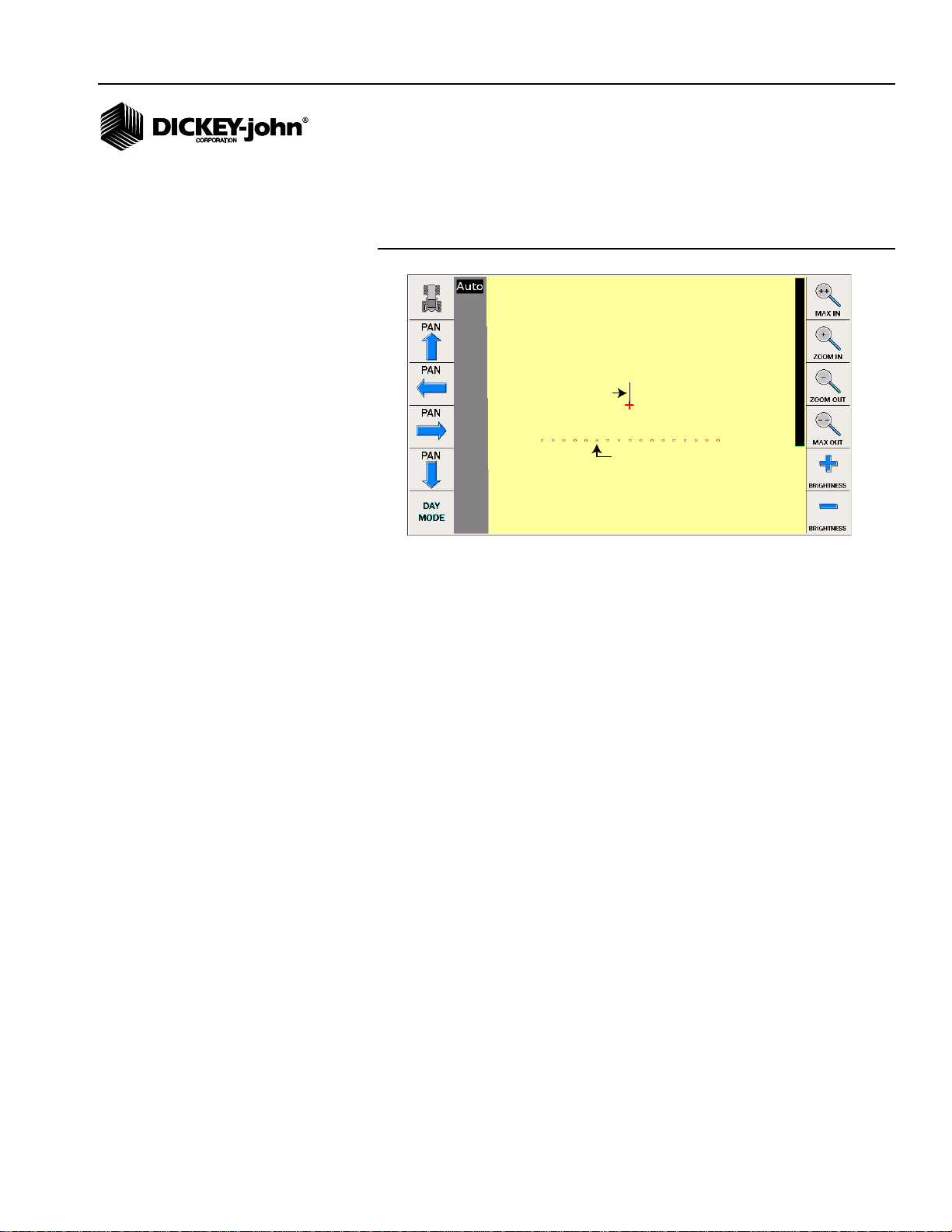
AUTO MODE
Auto mode automatically enables and disables individual planter sections
utilizing a GPS signal as previously planted areas or boundaries are
approached. As planted areas and boundaries are approached, the Auto
Section Control Main Menu screen indicates which outputs turn on and off
and the row control switch module/clutch folding module indicator lights
automatically turn on and off. Sections can be forced OFF in Auto mode.
IMPORTANT: If using boundary files for Auto Section Control, pay
close attention to the first pass a r ound the boundaries
to ensure outside clutches perform c orrectly. If the
boundary is drawn a little tight, outside clutches may
turn off when a percent of the section width is outside
the boundary based on the side-to-side overlap set at
the System Setup screen. To correct, run outer pass in
Manual mode and widen boundary file in PC software.
This scenario is typically prevalent when using WAAS.
NOTE: Pressing a section indicator
button represents what action
will occur when pressed not the
current action.
40 / SYSTEM OPERATION
Figure 40
Main Screen (Auto Mode)
MANUALLY FORCE SECTIONS OFF IN AUTO
Section indicators can be positioned to turn sections off while in Auto mode.
Auto Active button remains in Auto mode when sections are off.
1. Left Auto On/Off button turns all sections to the left of the section
indicator off (white) when pressed and is depicted in white on the
implement bar.
2. Right Auto On/Off button turns all sections to the right of the section
indicator off (white) when pressed and is depicted in white on the
implement bar.
3. Auto/Off buttons toggle all sections between the section indicators to
an off or Auto mode state.
Auto Section Control System
11001-1561B-201207
Page 43

OPERATOR’S MANUAL
1
2
3
4
5
On/Off button
automatically
turns sections
on and off
when section
indicators are
pressed
6
Toggles between
Auto/Manual
mode
Manual
Mode
Enabled
Implement
Bar
Sections
4. Left Section Indicator buttons define all sections in the left group
when moved. The color of the left and right indicator identifies the
action (on or off) to occur when section indicators are moved.
5. Right Section Indicator buttons define all sections in the right group
when moved. The color of the left and right indicator identifies the
action (on or off) to occur when section indicators are moved.
6. All On or All Off buttons turns all sections on or off when pressed and
moves left and right section indicators back to the outside.
MANUAL MODE
Manual mode allows the operator to manually control planter sections in the
event of a lost GPS signal or in special conditions, such as marking
headlands in Override. When the system is in manual mode, sections must
be turned on and off either on the Auto Section Control screen or the Row
Control Switch module or Clutch Fold module.
NOTE: Pressing a section indicator
button represents what action
will occur when pressed, not
the current action.
Figure 41
Section Indicators
MANUAL ON/OFF CONTROL OF SECTIONS
In manual mode, section indicators allow manual control of turning
implement sections on and off. Manual Active button must be pressed to
enable Manual mode.
1. Left On/Off button turns all sections to the left of the section indicator
on (green) or off (white) when pressed as depicted on the implement
bar.
2. Right On/Off button turns all sections to the right of the section
indicator on (green) or off (white) when pressed as depicted on the
implement bar.
3. On/off button turns all sections between the section indicators on or off
when pressed.
4. Left Section Indicator buttons define all sections in the left group to
be controlled by the left Auto/On/off button when moved. The color of
Auto Section Control System
11001-1561B-201207
SYSTEM OPERATION / 41
Page 44

OPERATOR’S MANUAL
the left and right indicator identifies the action (on or off) to occur when
section indicators are moved.
5. Right Section Indicator buttons define all sections in the right group
to be controlled by the right Auto/On/Off button when moved. The color
of the left and right indicator identifies the action (on or off) to occur
when section indicators are moved.
6. All On or All Off buttons turns all sections on or off when pressed and
moves left and right section indicators back to the outside.
ADDITIONAL OPERATING CONDITIONS
ADJUSTING IMPLEMENT POSITION
The Flip button performs a flip function that adjusts the implement to its
actual heading (North, South, East, West direction) if the initial tractor
movement is reverse, such as backing to a corner. The Flip button should
only be used after a true moving heading has been established to reposition
the implement.
The Cycle button located on the bottom of the Auto Section Control
terminal also performs the Flip functionality. Refer to (Figure 4) for Cycle
button location.
MARKING/PLANTING HEADLANDS
For use if headlands will be planted last or after all long internal areas of the
field have been planted.
IMPORTANT: Auto Section Control MUST be in Manual mode when
planting marked headlands.
The Override button allows headland swaths to be marked first and planted
last and allows for inland rows to automatically turn on and off when the
marked headland is reached.
To Mark a Headland Swath:
1. Drive to the beginning of the headland.
2. Press the Override button and put implement lift switch in down
position (hydraulic drive systems leave master switch off).
3. Start driving the headland swath to mark.
4. At the end of the headland swath, press the Override button or lift the
planter (implement lift switch in up position) to disengage override.
5. Continue to mark additional headland swaths until complete. Swaths
can be marked as follows:
– If the inner most headland is known, this is the only swath that is
required to be marked.
– If the inner most headland is not known, all swaths can be marked.
6. Ensure system is placed back in Auto mode once headland swaths
have been completed.
Planting a Marked Headland:
42 / SYSTEM OPERATION
Auto Section Control System
11001-1561B-201207
Page 45

OPERATOR’S MANUAL
Planting Marked
Headlands
(Manual Mode)
Planted in rows
(Auto Mode)
Inner
Headland
The system cannot differentiate between a marked and already planted
area. Therefore, when planting the marked headland, the section control
must be in manual. The field map planting area will appear in blue which is
the indication of overplanting. However, overplanting is not occurring since
the first pass was marked and no seeds were dropped.
If only the inner most headland is marked, this is the only headland that
requires the control to be in manual. All other headlands can be planted in
Auto mode.
Figure 42
Planting a Marked Headland
STORING HEADLANDS
The following steps should be performed to ensure that headlands are
saved:
1. At the Auto Section Main Work screen, press the Select Task button.
2. At the Select Task screen, press the Open Task button to return to the
Main Work screen.
3. No further action required.
LOST GPS SIGNAL
A NO GPS screen on the Auto Section Control terminal indicates a GPS
signal cannot be found, has been lost, or the signal quality is not at
acceptable levels.
Potential causes:
• GPS setup incorrect.
– Check GPS Setup screen for proper inputs
– Check GPS status at the Diagnostics screen
• GPS signal blocked.
– Move to a clear area
• GPS receiver failure.
– Check receiver connection
In the event of a lost GPS signal, switch Auto Section Control to Manual
mode to continue planting.
Auto Section Control System
11001-1561B-201207
SYSTEM OPERATION / 43
Page 46

OPERATOR’S MANUAL
Figure 43
Auto No GPS
OUT OF FIELD RANGE
An Out of Field screen on the Auto Section Control terminal occurs when
the field is outside of range to display on the screen.
Select the correct field or start a new task to continue.
Figure 44
Out of Field Range
44 / SYSTEM OPERATION
Auto Section Control System
11001-1561B-201207
Page 47

OPERATOR’S MANUAL
SMITH
TERMINAL STORAGE CAPACITY
All created and imported fields are stored on the Auto Section Control
terminal. Storage capacity is indicated on the Auto Section Control
terminal Main Menu screen.
When full, storage can be cleared or deleted by clearing tasks or deleting
files. Task or files cannot be exported.
TIP: It is recommended that imported and created fields are cleared
after use to avoid the system from running slow.
CLEAR TASK
1. At the Select Task screen on the IntelliAg VT, select the task to be
cleared.
2. Press the Clear Task button.
3. At the Clear Task Coverage screen, verify the correct task is selected.
4. Press the OK button to delete.
NOTE: The Clear Task button only
appears for an existing task
stored on the terminal.
IMPORTANT: Deleted tasks cannot be restored.
Figure 45
Clear Task Coverage Screen
Auto Section Control System
11001-1561B-201207
TERMINAL STORAGE CAPACITY / 45
Page 48

OPERATOR’S MANUAL
SMITH
DELETE/RENAME FILES
NOTE: Individual clients, farms, fields,
and tasks can be renamed at
the Rename/Delete screen by
pressing the appropriate yellow
selection box. Use virtual
keypad to enter new name.
Individual clients, farms, fields, and tasks can be deleted.
1. At the Select Task screen, select the desired client, farm, field, or task
to delete.
2. Press the Rename/Delete button.
3. At the Rename/Delete screen, press the appropriate Delete button.
4. Verify the appropriate data is selected and press the OK button to
delete.
IMPORTANT: Deleted files cannot be restored.
Figure 46
Delete Files Screen
46 / TERMINAL STORAGE CAPACITY
Auto Section Control System
11001-1561B-201207
Page 49

OPERATOR’S MANUAL
Average GPS
Rate must be
lower than
200 ms
200 ms
DIAGNOSTICS
The Diagnostics screen provides information about the Auto Section
Control software version and GPS status. Information on the screen cannot
be edited.
Press the Diagnostics button to access the GPS Status and System
Information screens.
GPS STATUS
The GPS Status screen provides information about the current status of the
GPS functionality used for troubleshooting. Information on the screen
cannot be edited.
1. At the Diagnostics screen, press the Status button to access the GPS
Status screen.
The average GPS Rate must be lower than 200 ms for the 5 Hz
requirement to be met.
Figure 47
GPS Status Screen
Auto Section Control System
11001-1561B-201207
DIAGNOSTICS / 47
Page 50

OPERATOR’S MANUAL
SYSTEM INFORMATION
The System Information screen provides system software version
information. Information on this screen cannot be edited.
1. At the Diagnostics screen, press the Information button to access the
System Information screen.
Figure 48
System Information Screen
48 / DIAGNOSTICS
Auto Section Control System
11001-1561B-201207
Page 51

OPERATOR’S MANUAL
Start
Test
CLUTCH SECTION CHECK
A recommended pre-test to verify correct module and clutch assignment
ensures that clutches turn on and off appropriately.
To perform test:
1. At the Diagnostics screen, press the Section Check button.
1. Enter the cycle time duration of turning clutches on and off.
2. Select the type of test to perform
– All output test
– Single output test
3. Press the Start Test button to begin test.
4. Press the Stop Test button to end test.
IMPORTANT: Master switch and all clutch switches must be ON, if
equipped.
Figure 49
Clutch Section Check
Auto Section Control System
11001-1561B-201207
Cycle Time
Desired cycle time duration of turning clutches on and off during test.
All Output Test
Turns all clutches on and off at the same time.
Single Output Test
Selects which section to perform an individual section test. Plus button
goes to next higher section. Minus button goes to next lower section.
DIAGNOSTICS / 49
Page 52

OPERATOR’S MANUAL
50 / DIAGNOSTICS
Auto Section Control System
11001-1561B-201207
Page 53

OPERATOR’S MANUAL
TROUBLESHOOTING
FIRST PASS NEXT TO BOUNDARY IS SHUTTING OFF
ROWS WHEN USING BOUNDARY FILES
• Outside clutches will turn off when a section width is outside the
boundary based on the side-to-side overlap setting. To correct, run
outer pass in Manual mode and widen boundary file in PC software to
prevent this issue next time. This scenario is typically prevalent when
using WAAS.
AUTO SECTION CONTROL TERMINAL DOES NOT POWER
ON
• Verify that the Auto Section Control terminal ignition wire is connected
to switched power source.
• Check fuse connections of Auto Section Terminal Interface harness p/n
467980458 to the Tractor VT harness p/n 467980451A and to the
Tractor Power harness p/n 467980455.
AUTO SECTION CONTROL TERMINAL READS NO GPS
SIGNAL
• Poor GPS signal. Check GPS Status on the Auto Section Control
Diagnostics screen for signal status.
• Verify that GPS RS232 receiver is connected to the Auto Section
Terminal Interface Harness p/n 467980458 and not the Tractor
Harness p/n 467980451A.
• Verify that proper settings have been entered at the GPS Setup screen
for quality of GPS signal. An average GPS Rate must be lower than
200 ms for the 5 Hz requirement to be met.
• Check GPS status at the Auto Section Control Diagnostics screen for
signal status.
• GPS may be blocked. Move to a clear area.
• Check that receiver connection is powered up and secure.
To continue planting in the event of a lost GPS signal, switch Auto Section
Control to Manual mode and use section switch on CFM module.
AUTO SECTION CONTROL SCREEN SHOWS GAPS IN
SWATH PATTERN (SIDE TO SIDE)
• Adjust the Side-to-Side overlap percentage to adjust the amount of
overlap and/or skip at the System Setup screen. The higher the
percentage the larger the planting overlap. Decreasing the percentage
reduces the overlap and increases the skip.
Auto Section Control System
11001-1561B-201207
TROUBLESHOOTING / 51
Page 54

OPERATOR’S MANUAL
• Clutch assignment may be incorrect.
– Verify that output modules have been correctly assigned to rows at
the Module Configuration screen.
– Verify that row shutoff switches are correctly assigned to
corresponding outputs.
– Run a Clutch Section check to verify the order of clutch sections
shut on and off correctly (refer to Diagnostics screen).
auto section control screen shows gaps in swath pattern (start/stop)
– Driving to wide.
– GPS accuracy issue.
– Verify Physical Layout screen to verify layout is correct.
AUTO SECTION CONTROL SCREEN SHOWS GAPS IN
SWATH PATTERN (START/STOP)
– Swath coverage map is drawn based on seed flow. If stopped in the
field, there will be a slight delay in seed flow when starting up
causing a slight skip in the coverage map, i.e., seeding rate must
exceed row fail rate before coverage can be painted.
AUTO SECTION CONTROL SCREEN SHOWS OUT OF
FIELD
• Wrong field loaded.
• The field is too far out of range to display on the screen.
ROWS ARE NOT SHUTTING OFF AND TURNING ON AS
EXPECTED
• Implement measurements could be incorrect.
– Verify that measurements were entered as described at Physical
Layout screen.
– X measurements should be taken from the hitch pivot point to
where the seed is placed in the ground.
– Y coordinates are measured from implement center to the center of
each channel.
– Verify implement/channel assignment are correct at the Physical
Layout screen.
• Verify that the correct Implement Layout type was selected (3 point
hitch, towed hitch, rigid cart mount, or tow-behind cart).
• When operating in Monitor only mode there are no rows assigned to a
channel on the IntelliAg. However, row assignment must be entered at
the Physical Layout screen for Auto Section to perform correctly.
• If operating with only one control channel, the Y coordinate on the
Physical Layout screen should remain at “0”.
• Clutch assignment may be incorrect.
– Verify that output modules have been correctly assigned to rows at
the Module Configuration screen.
– Verify that row shutoff switches are correctly assigned to
corresponding outputs.
– Run a Clutch Section check to verify the order of clutch sections
shut on and off correctly (refer to Diagnostics screen).
• Swath control is not in Auto mode.
52 / TROUBLESHOOTING
Auto Section Control System
11001-1561B-201207
Page 55

OPERATOR’S MANUAL
SWATH PATTERN IS OFFSET FROM THE SWATH
DIRECTION INDICATOR
• Implement measurements could be incorrect.
– Verify that measurements were entered as described at Physical
Layout screen.
– X measurements should be taken from the hitch pivot point to
where the seed is placed in the ground.
– Y coordinates are measured from implement center to the center of
each channel.
• Check row pattern setup at IntelliAg I/O screen.
• Check Physical Layout screen to verify layout is correct.
ROWS TURNING ON/OFF TOO EARLY OR LATE WHEN
ENTERING OR EXITING HEADLANDS
• Check Run In/Run Out overlap settings.
• Verify and check GPS calibration and run a new GPS calibration test, if
required.
• Verify that an additional delay value is not entered at the IntelliAg
Clutch Configuration screen.
• Verify implement measurements are correct.
AUTO SECTION CONTROL TERMINAL INDICATES
INITIALIZING PLEASE WAIT
• GPS has not been detected.
DATA LOSS AFTER POWER CYCLE
• Check power connections.
• Ensure ignition wire is conntected to switched source.
• Ensure console has continuous power.
GPS ACCURACY
RTK (1 inch pass-to-pass accuracy)
RTK is used with a reference receiver placed on a known reference point.
This receiver then communicates over a radio signal to the roving receiver
to determine position or navigation. RTK is a highly precise technique that
results in one inch year-to-year accuracy. RTK GPS requires two
specialized GPS receivers and two radios. One GPS receiver is set as a
base station with a 6 mile radius of the field you are working so it can send
the correction message to the roving receiver. Both receivers collect extra
data from the GPS satellites, known as L2 Band, that enables better
precision.
WAAS (6-8 inch accuracy) AND OMNISTAR HP (XP 3-5 inch
pass-to-pass accuracy) HP (2-4 inch pass-to-pass accuracy)
Auto Section Control System
11001-1561B-201207
Waas and Omnistar services have many GPS receivers at known reference
locations that send the correction messages to control stations that uplink
the message to a geostationary satellite. The geostationary satellite (WAAS
or OmniSTAR) then sends the correction message to the GPS antenna on
the vehicle applying the correction.
TROUBLESHOOTING / 53
Page 56

OPERATOR’S MANUAL
IMPORTANT: OmniSTAR correction types require paid subscription.
For an AgGPS 252 or 332 receiver, select either
OmniST AR HP/XP or OmniSTAR HP/XP-VBS. Refer to Ag
GPS Autoseed fast restart tech nology.
54 / TROUBLESHOOTING
Auto Section Control System
11001-1561B-201207
Page 57

OPERATOR’S MANUAL
ERROR CODES
Various alarm conditions may be presented whenever the system
encounters an abnormal condition or detects a specific alarm. Alarms are
typically in a full screen display describing the alarm and, dependent upon
the alarm type, may give instructions on how to fix the alarm. Each alarm
type has an associated alarm number .
Some alarms require a specific action before the alarm condition will cease.
In these cases, instructions are indicated on the alarm display.
Other alarms can be acknowledged by pressing the Alarm Cancel button
of ESC key on the IntelliAg virtual terminal.
For any failure that persists, contact DICKEY-john Technical Support at
1-800-637-3302
Error
Codes
100 ECU Control Module
101 ECU Control Module
102 GPS Signal Quality Low GPS signal quality has degraded below a usable
103 Internal Data Storage
104 Internal Data Storage
105 In Setup with System
200 Setting Change Active System settings changed and operating began
Error Probable Cause Corrective Action
Lost
Intermittent
Space Low
Space is Critical
Running
COMMUNICATION WITH AN ACTIVE
MODULE HAS FAILED
1. Damaged CAN or module harness.
2. Blown module harness fuse.
3. Defective module.
1. A module that had previously failed
communication has come online.
level.
Internal data storage is low on free space. 1. Clear old coverage lags.
Internal data storage is low on free space. 1. Clear old coverage lags.
Detected implement controller running and not in
Ready state.
before system could initialize.
1. Identify missing module in the Module
Configuration list. Inspect CAN/module harness
of the missing module for damage. Repair or
replace harness.
2. Inspect module harness fuse, replace if
necessary.
3. Identify missing module in the Module
Configuration list. Inspect missing module for
damage or replace.
1. Inspect harness connections to this module.
1. Check GPS antenna corrections.
2. Inspect GPS harness for damage.
3. Check GPS communication settings.
4. Inspect GPS receiver for damage.
2. Delete unused fields.
3. Delete unused farms.
4. Delete unused clients.
2. Delete unused fields.
3. Delete unused farms.
4. Delete unused clients.
1. Complete setup operations.
2. Complete Task Selection.
3. Return to the Work Screen.
1. Stop operating by lifting implement, turning
master switch off, or stopping.
2. Restart the system.
Auto Section Control System
11001-1561B-201207
ERROR CODES / 55
Page 58

OPERATOR’S MANUAL
Auto Section
Control Terminal
ISO
Tractor
Hitch
WSMT 2 ‘T’ Harness
467980850
Add a CAN Extension
or
CAN Terminator
WSMB
Tru Count
Output Module
Tru Count
Solenoid
Modules
(available from
Tru Count)
Tru Count
Clutch Harness
467983505
Hitch Extension
Harness
46798013x
WSMT 2
PDC Module
CFM or
RSM
Switch
Module
Harness
467980330
Auto
Section
Terminal
Interface
Harness
467980337
GPS input from
GPS Receiver
Terminator
Corner A
Post
GTA Console
Harness
GTA2
To
Auxiliary
12 V in Cab
GPS Receiver connects
direct to RS232 on
Auto Section Terminal
Harness. Refer to Auto
Section Control
Setup to transmit GPS
signal over CAN.
Cab Harnessing
Implement Harnessing
APPENDIX A
AGCO GTA CONSOLE
AGCO tractors with a factory installed cab harness and GTA console
requires the GTASWATHKIT. This kit contains the required harnesses that
connect to the GTA console and auxiliary power connector in the cab.
Figure 50
AGCO GTA Console and RSM or CFM Harness Connections
56 / ERROR CODES
Auto Section Control System
11001-1561B-201207
Page 59

OPERATOR’S MANUAL
Auto Section
Control Terminal
Auto
Section
Terminal
Interface
Harness
467980337
GPS input from
GPS Receiver
CAN Pass Through
to Aux Interface
Module 467980336
ISO
Tractor
Hitch
WSMT 2 ‘T’ Harness
467980850
Add a CAN Extension
or
CAN Terminator
WSMB
Tru Count
Output Module
Tru Count
Solenoid
Modules
(available from
Tru Count)
Tru Count
Clutch Harness
467983505
Hitch Extension
Harness
46798013x
WSMT 2
PDC Module
Corner A
Post
GS2 Console
Harness
CFM or
RSM
Switch
Module
Harness
467980335
Starfire
GPS Interface
Harness
467980460
To Auxiliary
12 V in Cab
Implement Harnessing
Cab Harnessing
APPENDIX B
JOHN DEERE GS2 CONSOLE
John Deere tractors with a factory installed cab harness and GS2 console
requires the GS2SWATHKIT. This kit contains the required harnesses that
connect to the GS2 console and auxiliary power connector in the cab.
Figure 51
John Deere GS2 Console and RSM or CFM Module Harness Connections
Auto Section Control System
11001-1561B-201207
ERROR CODES / 57
Page 60

OPERATOR’S MANUAL
Do not unplug
male connector of
GPS receiver harness
DEERE GS2 CONSOLE CAB HARNESS CONNECTIONS
1. Standing on the outside of the cab near the Starfire GPS receiver,
remove the dust plug connector on the GPS receiver harness.
IMPORTANT: Do not unplug the male connector of the GPS receiver
harness connected to the John Deere cab/electronics.
Figure 52
Remove GPS Receiver Dust Plug from Starfire Receiver Harness
2. Connect the DICKEY-john (Starfire) Interface harness part number
46798-0460 to the dust plug and the female connector of the GPS
Receiver harness.
Figure 53
Attach Interface Harness to Starfire Receiver Harness
58 / ERROR CODES
Auto Section Control System
11001-1561B-201207
Page 61

OPERATOR’S MANUAL
3. Inside the cab, connect CFM/RSM Module harness part number
46798-0335 to the mating 4 pin connector of the GS2 console harness.
Figure 54
Connect CFM or RSM Harness to GS2 Console
4. Connect the mating connectors of the Auxiliary Interface Module
harness part number 46798-0336 to the CFM/RSM Switch Module
harness part number 46798-0335.
Figure 55
Connector CFM or RSM Harness to Auxiliary Interface Harness
Auto Section Control System
11001-1561B-201207
ERROR CODES / 59
Page 62

OPERATOR’S MANUAL
5. Connect the Auto Section Control harness part number 46798-0337 to
the mating connector of the Auxiliary Interface harness part number
46798-0336.
Figure 56
Connect Auto Section Control Harness to Aux Interface Harness
6. Plug in the Auxiliary Power 3 pin connector of the Auto Section Control
harness part number 46798-0337 to the auxiliary power in the cab.
Figure 57
Connect Auto Section Control Connector to Cab Auxiliary Power
60 / ERROR CODES
Auto Section Control System
11001-1561B-201207
Page 63

OPERATOR’S MANUAL
7. Connect the RS232 connector from the Starfire Interface cable to the
RS232 connector of the Auto Section Control harness part number
46798-0337.
Figure 58
Connect Starfire RS232 to Auto Section Control RS232
Auto Section Control System
11001-1561B-201207
ERROR CODES / 61
Page 64

OPERATOR’S MANUAL
62 / ERROR CODES
Auto Section Control System
11001-1561B-201207
Page 65

Dealers have the responsibility of calling to the attention of their customers the following
warranty prior to acceptance of an order from their customer for any DICKEY-john product.
DICKEY-john® WARRANTY
DICKEY-john warrants to the original purchaser for use that, if any part of the product
proves to be defective in material or workmanship within one year from date of original
installation, and is returned to DICKEY-john within 30 days after such defect is discovered,
DICKEY-john will (at our option) either replace or repair said part. This warranty does not apply
to damage resulting from misuse, neglect, accident, or improper installation or maintenance; any
expenses or liability for repairs made by outside parties without DICKEY-john’s written consent;
damage to any associated equipment; or lost profits or special damages. Said part will not be
considered defective if it substantially fulfills the performance expectations. THE FOREGOING
WARRANTY IS EXCLUSIVE AND IN LIEU OF ALL OTHER WARRANTIES OF
MERCHANTABILITY, FITNESS FOR PURPOSE, AND OF ANY OTHER TYPE, WHETHER
EXPRESS OR IMPLIED. DICKEY-john neither assumes nor authorizes anyone to assume for it
any other obligation or liability in connection with said part and will not be liable for
consequential damages. Purchaser accepts these terms and warranty limitations unless the
product is returned within fifteen days for full refund of purchase price.
For DICKEY- john Service Department, call
1-800-637-3302 in either the U.S.A. or Canada
Headquarters:
5200 Dickey-john Road, Auburn, IL USA 62615
TEL: 217 438 3371, FAX: 217 438 6012, WEB: www.dickey-john.com
Europe:
DICKEY-john Europe S.A.S, 165, boulevard de Valmy, 92706 – Colombes – France
TEL: 33 (0) 1 41 19 21 80, FAX: 33 (0) 1 47 86 00 07 WEB: www.dickey-john.eu
Copyright 2012 DICKEY-john Corporation
Specifications subject to change without notice.
 Loading...