

Page 1
Operator’s Manual
CTA4000
Air Drill Implement
Manufacturing, Inc.
www.greatplainsmfg.com
Read the operator’s manual entirely. When you see this symbol, the subsequent
instructions and warnings are serious - follow without exception. Your life and
!
the lives of others depend on it!
2007+
17186
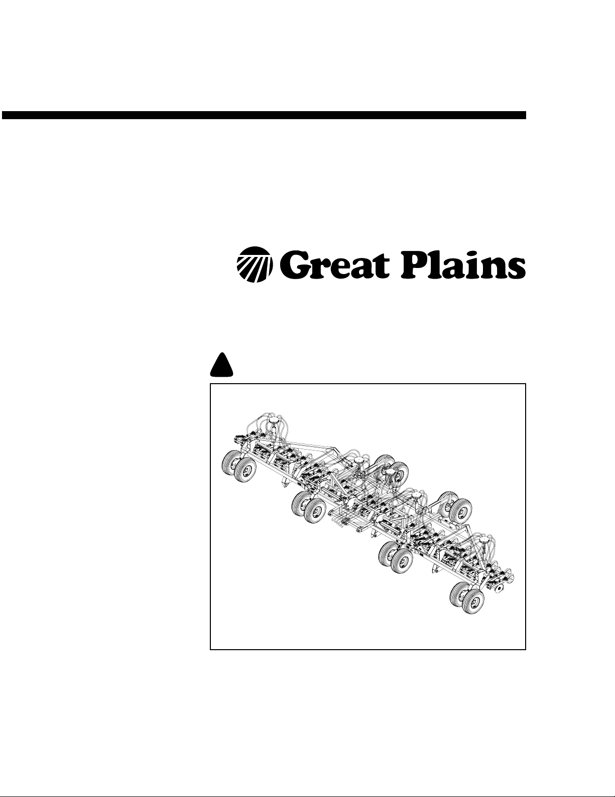
Illustrations may show optional equipment not supplied with standard unit.
© Copyright 2010 Printed 08/03/2010 160-269M-A
Page 2

Page 3

Table of Contents
Important Safety Information ....................................1
Safety Decals ...............................................................6
Introduction ..............................................................10
Document Family .......................................................10
Models Covered by this Manual .................................10
Description of Unit ......................................................10
Intended Usage ......................................................10
Definitions...............................................................10
Using This Manual......................................................11
Owner Assistance ......................................................11
Preparation and Setup .............................................12
Pre-Setup Checklist....................................................12
Hitching ......................................................................12
Hitch Link................................................................13
Make Seed Hose Connections...................................13
Make Electrical Connections ......................................14
Make Hydraulic Connections......................................14
Hydraulic Circuit Connections ................................15
Bleeding Hydraulics....................................................15
Bleeding Lift Hydraulics..........................................16
Bleeding Fold Hydraulics........................................18
Load Sensing Setup ...............................................19
Eyebolt Adjustment ....................................................20
Operating Instructions.............................................21
General Description....................................................21
Planting Operation..................................................21
Pre-Start Checklist .....................................................21
Transport ....................................................................22
Pre-Transport Checklist..........................................23
Folding and Unfolding ................................................24
Folding the Implement............................................24
Unfolding the Implement.........................................26
Opener Operation.......................................................27
Tractor-Specific Circuit Operation ..........................27
John Deere tractors with Sound-Gard ® Body ...27
John Deere 7000 Series tractors........................27
John Deere 8000 Series tractors........................27
Case-IH Magnum tractors ..................................27
Other Tractors ....................................................27
Initial Frame Down-Pressure..................................27
Initial Seeding Depth ..............................................28
Fan Speed.............................................................. 29
Weight Transfer ......................................................... 29
Marker Operation ....................................................... 30
Field Operations......................................................... 31
Final Field Checklist ............................................... 31
Planting Sequence ................................................. 31
Planting .................................................................. 31
Seed Monitor.......................................................... 31
Parking....................................................................... 32
Storage ...................................................................... 32
Adjustments ............................................................. 33
Planting Depth.................................................... 33
Frame Level ............................................................... 34
Implement Lift Switch Adjustment.............................. 34
Frame Weight ............................................................ 35
Adjusting Weight Transfer.......................................... 36
Sub-Frame Down-Force ............................................ 37
Hydraulic Down Pressure....................................... 37
Opener Down Force........................................... 38
Opener-Subframe Adjustment ................................... 39
Row Unit Adjustments................................................ 40
Opener Height........................................................ 41
Row Unit Down Pressure (Spring) ......................... 41
Disk Blade Adjustments ......................................... 42
Adjusting Disc Contact ....................................... 42
Disk Scraper Adjustments...................................... 42
Seed Firmer Adjustments....................................... 43
Keeton Seed Firmer Adjustment ........................ 43
Seed-Lok™ Seed Firmer Lock-Up ..................... 43
Opener Depth (Press Wheel Height) .....................44
Troubleshooting....................................................... 45
Maintenance and Lubrication ................................. 49
Seed Flap Replacement (s/n EE1169-) ..................... 50
Seed Flap Replacement (s/n EE1170+) ....................50
Lubrication ................................................................. 51
Options ..................................................................... 53
Blockage Detector...................................................... 53
Hydraulic Bypass Kit .................................................. 53
Markers ...................................................................... 53
Press Wheels............................................................. 53
Seed Firmers ............................................................. 54
© Copyright 1999, 2006, 2007, 2008. 2010 All rights Reserved
Great Plains Manufacturing, Inc. provides this publication “as is”without warranty of any kind, either expressed or implied. While every precaution has been taken in the preparation
of this manual, Great Plains Manufacturing, Inc. assumes no responsibility for errors or omissions. Neither is any liability assumed for damages resulting from the use of the information contained herein. Great Plains Manufacturing, Inc. reserves the right to revise and improve its products as it sees fit. This publication describes the state of this product at
the time of its publication, and may not reflect the product in the future.
The following are trademarks of Great Plains Mfg., Inc.: Application Systems, Ausherman, Land Pride, Great Plains
All other brands and product names are trademarks or registered trademarks of their respective holders.
08/03/2010 160-269M-A
Great Plains Manufacturing, Incorporated Trademarks
Printed in the United States of America.
Page 4

CTA4000
Seed-Lok® Seed Firmer ........................................ 54
Keeton Seed Firmer............................................... 54
Weight Kits................................................................. 54
Appendix................................................................... 55
Specifications and Capacities .................................... 55
Tire Inflation Chart ..................................................... 55
Torque Values Chart ................................................. 56
Hydraulic Diagram ..................................................... 57
CTA4000 Hydraulic Circuit Assignments............... 57
Warranty .................................................................... 58
Index ......................................................................... 59
160-269M-A 08/03/2010
Page 5
Important Safety Information
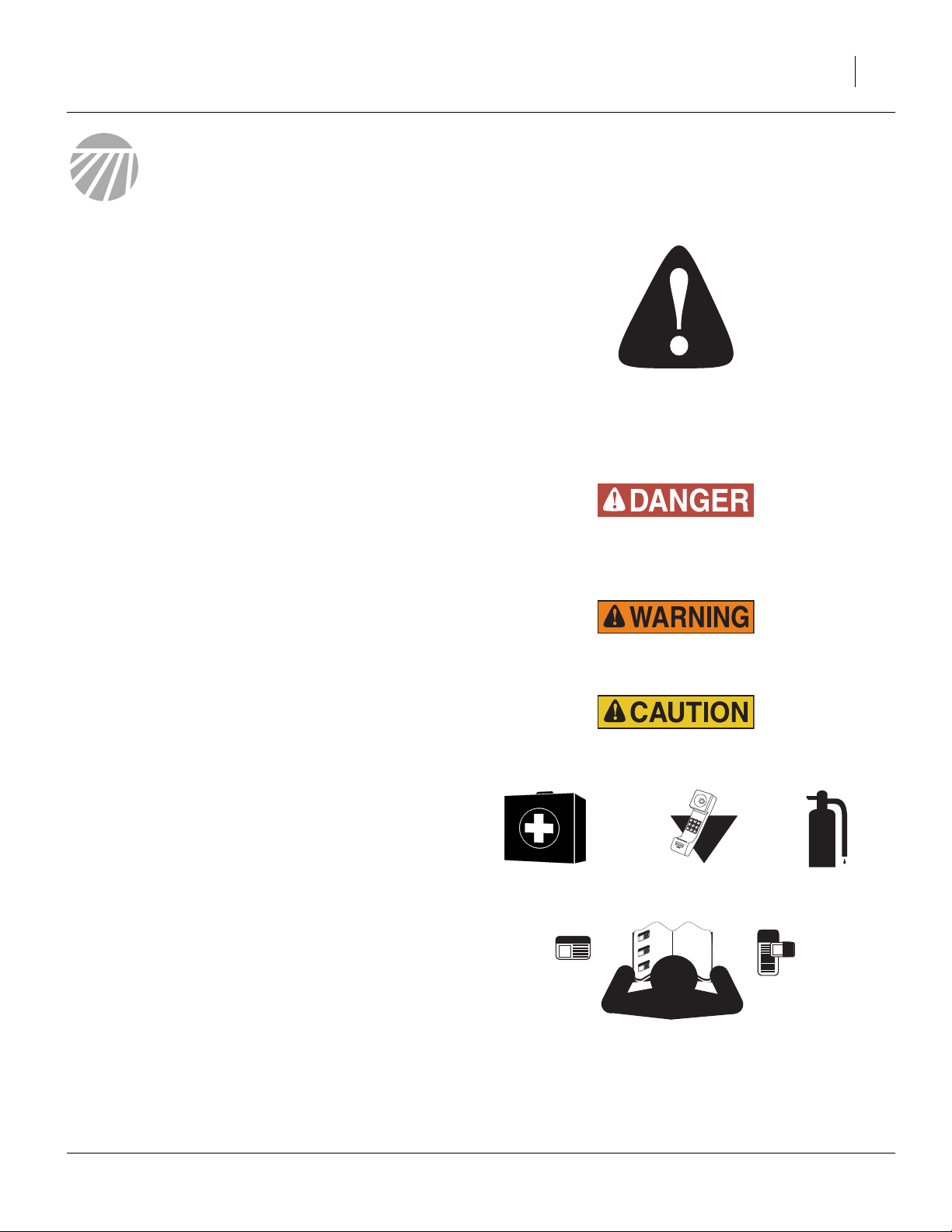
Look for Safety Symbol
The SAFETY ALERT SYMBOL indicates there is a
potential hazard to personal safety involved and extra
safety precaution must be taken. When you see this
symbol, be alert and carefully read the message that follows it. In addition to design and configuration of equipment, hazard control and accident prevention are
dependent upon the awareness, concern, prudence and
proper training of personnel involved in the operation,
transport, maintenance and storage of equipment.
Be Aware of Signal Words
Signal words designate a degree or level of hazard seriousness.
DANGER indicates an imminently hazardous situation
which, if not avoided, will result in death or serious injury.
This signal word is limited to the most extreme situations,
typically for machine components that, for functional purposes, cannot be guarded.
WARNING indicates a potentially hazardous situation
which, if not avoided, could result in death or serious
injury, and includes hazards that are exposed when
guards are removed. It may also be used to alert against
unsafe practices.
CAUTION indicates a potentially hazardous situation
which, if not avoided, may result in minor or moderate
injury. It may also be used to alert against unsafe practices.
1
Prepare for Emergencies
▲ Be prepared if a fire starts
▲ Keep a first aid kit and fire extinguisher handy.
▲ Keep emergency numbers for doctor, ambulance, hospital
and fire department near phone.
000
112
911
999
Be Familiar with Safety Decals
▲ Read and understand “Safety Decals” on page 6, thor-
oughly.
▲ Read all instructions noted on the decals.
▲ Keep decals clean. Replace damaged, faded and illegible
decals.
08/03/2010 160-269M-A
Page 6
2 CTA4000
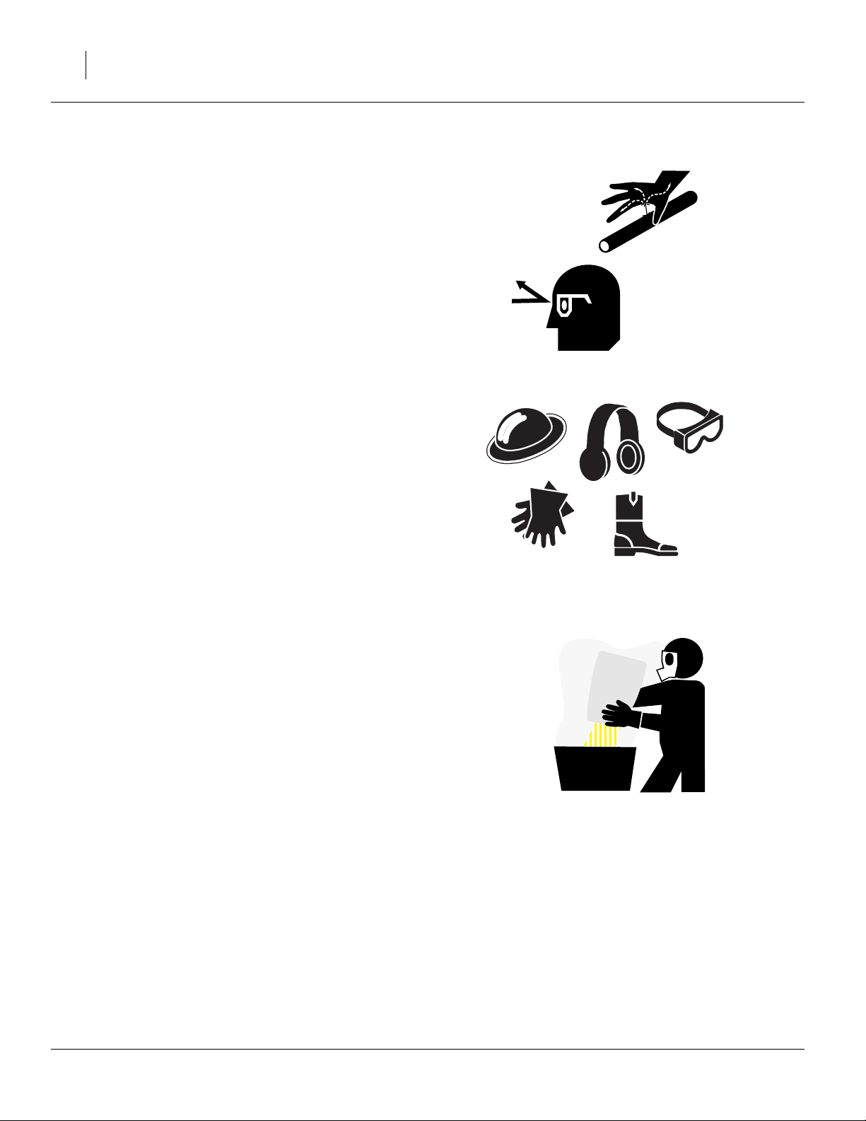
Avoid High Pressure Fluids
Escaping fluid under pressure can penetrate the skin,
causing serious injury.
▲ Avoid the hazard by relieving pressure before disconnecting
hydraulic lines.
▲ Use a piece of paper or cardboard, NOT BODY PARTS, to
check for suspected leaks.
▲ Wear protective gloves and safety glasses or goggles when
working with hydraulic systems.
▲ If an accident occurs, seek immediate medical attention
from a physician familiar with this type of injury.
Wear Protective Equipment
▲ Wear protective clothing and equipment.
▲ Wear clothing and equipment appropriate for the job. Avoid
loose-fitting clothing.
▲ Because prolonged exposure to loud noise can cause hear-
ing impairment or hearing loss, wear suitable hearing protection such as earmuffs or earplugs.
▲ Because operating equipment safely requires your full
attention, avoid wearing entertainment headphones while
operating machinery.
Handle Chemicals Properly
Agricultural chemicals can be dangerous. Improper use
can seriously injure persons, animals, plants, soil and
property.
▲ Do not use liquid treatments with implement.
▲ Read and follow chemical manufacturer’s instructions.
▲ Wear protective clothing.
▲ Handle all chemicals with care.
▲ Avoid inhaling smoke from any type of chemical fire.
▲ Never drain, rinse or wash dispensers within 100 feet (30m)
of a freshwater source, nor at a car wash.
▲ Store or dispose of unused chemicals as specified by chemi-
cal manufacturer.
▲ Dispose of empty chemical containers properly. Laws gen-
erally require power rinsing or rinsing three times, followed
by perforation of the container to prevent re-use.
160-269M-A 08/03/2010
Page 7
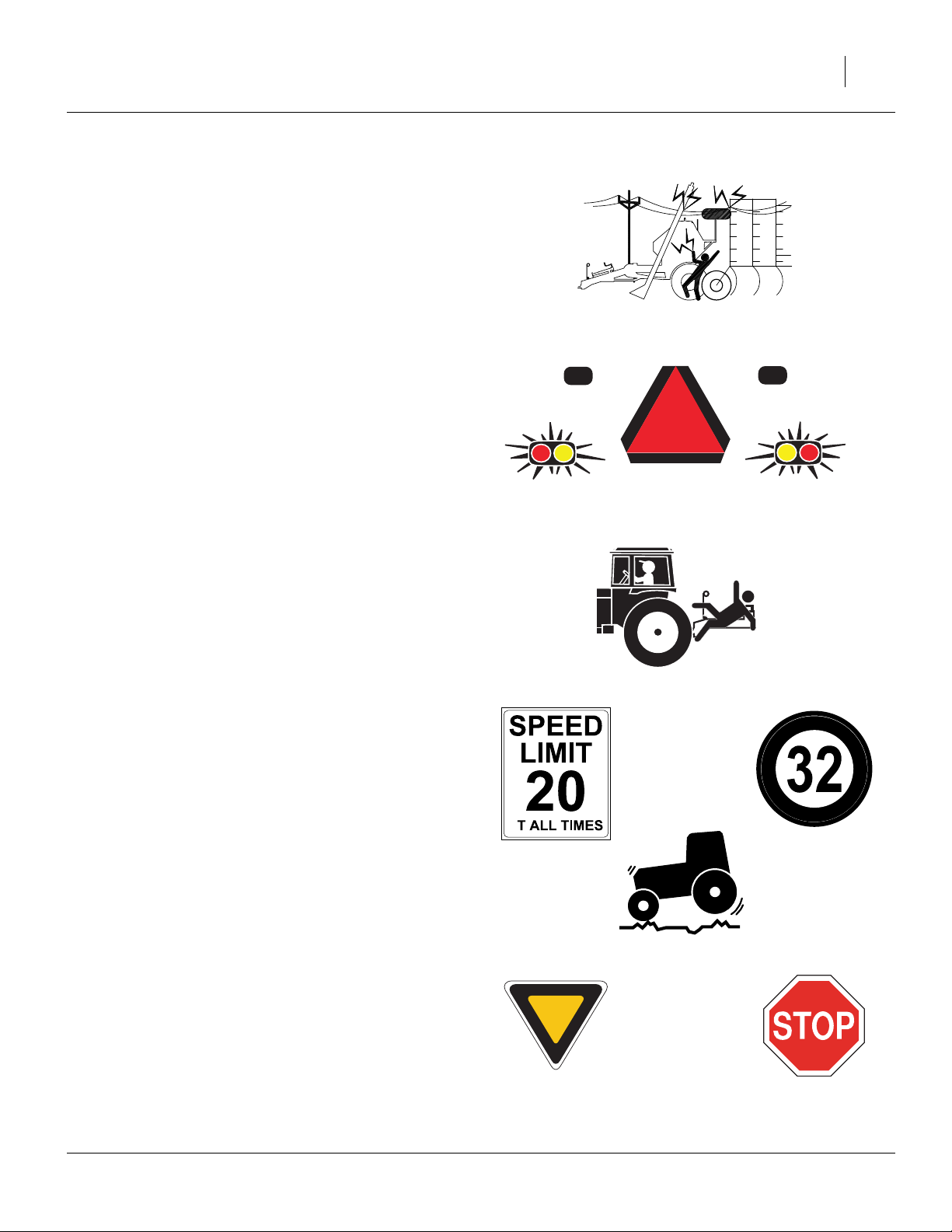
Check for Overhead Lines
Seed auger or implement markers contacting overhead
electrical lines can introduce lethal voltage levels on
implement, cart and tractor frames. A person touching
almost any metal part can complete the circuit to ground,
resulting in serious injury or death. At higher voltages,
electrocution can occur without direct contact.
▲ Avoid overhead lines during seed loading/unloading and
marker operations.
Use Safety Lights and Devices
Slow-moving tractors and towed implements can create
a hazard when driven on public roads. They are difficult
to see, especially at night.
▲ Use flashing warning lights and turn signals whenever driv-
ing on public roads.
▲ Use lights and devices provided with implement and cart.
3
Keep Riders Off Machinery
Riders obstruct the operator’s view. Riders could be
struck by foreign objects or thrown from the machine.
▲ Never allow children to operate equipment.
▲ Keep all bystanders away from machine when folding/
unfolding, raising/lowering markers, raising/lowering
openers, and transporting.
Transport Machinery Safely
Maximum transport speed for implement is 20 mph (32
kph). Some rough terrains require a slower speed. Sudden braking can cause a towed load to swerve and
upset.
▲ Do not exceed 20 mph (32 kph). Never travel at a speed
which does not allow adequate control of steering and stopping. Reduce speed if towed load is not equipped with
brakes.
▲ Comply with national, regional and local laws.
▲ Follow your tractor manual recommendations for maximum
hitch loads. Insufficient weight on tractor steering wheels
will result in loss of control.
A
▲ Carry reflectors or flags to mark implement and cart in case
of breakdown on the road.
▲ Keep clear of overhead power lines and other obstructions
when transporting. Refer to transport dimensions under
“Specifications and Capacities” on page 55.
08/03/2010 160-269M-A
Page 8
4 CTA4000
Shutdown and Storage
▲ Clean out and safely store or dispose of residual chemicals.
▲ Secure implement using blocks and transport locks. Lower
openers if not locked up.
▲ Store in an area where children normally do not play.
Practice Safe Maintenance
▲ Understand procedure before doing work. Use proper tools
and equipment. Refer to this manual for additional information.
▲ Work in a clean, dry area.
▲ Put tractor in park, turn off engine, and remove key before
performing maintenance.
▲ Make sure all moving parts have stopped and all system
pressure is relieved.
▲ Disconnect battery ground cable (-) before servicing or
adjusting electrical systems or before welding on implement.
▲ Inspect all parts. Make sure parts are in good condition and
installed properly.
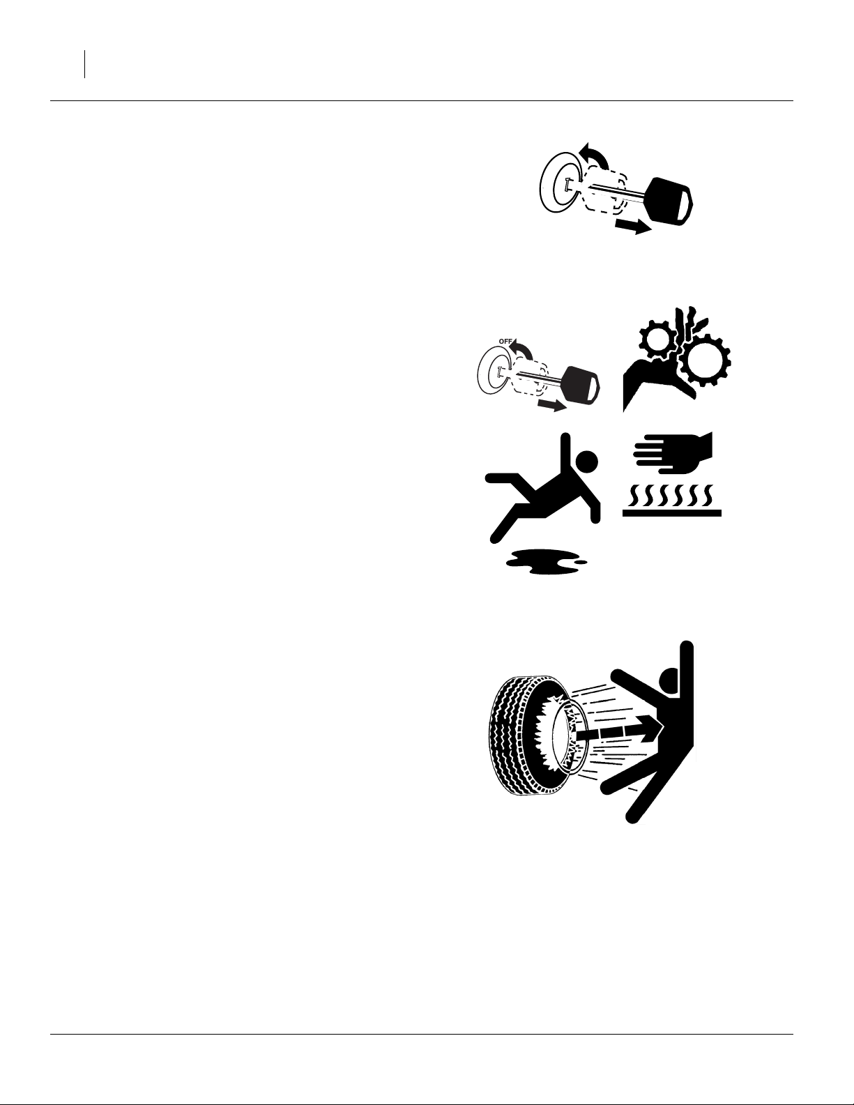
OFF
▲ Remove buildup of grease, oil or debris.
▲ Remove all tools and unused parts from implement before
operation.
Tire Safety
Tire changing can be dangerous and should be performed by trained personnel using correct tools and
equipment.
▲ When inflating tires, use a clip-on chuck and extension hose
long enough for you to stand to one side–not in front of or
over tire assembly. Use a safety cage if available.
▲ When removing and installing wheels, use wheel-handling
equipment adequate for weight involved.
160-269M-A 08/03/2010
Page 9
Safety At All Times
Thoroughly read and understand the instructions in this
manual before operation. Read all instructions noted on
the safety decals.
▲ Be familiar with all cart and implement functions.
▲ Operate machinery from the driver’s seat only.
▲ Do not leave implement unattended with tractor engine
running.
▲ Do not dismount a moving tractor. Dismounting a moving
tractor could cause serious injury or death.
▲ Do not stand between the tractor and implement during
hitching.
▲ Keep hands, feet and clothing away from power-driven
parts.
▲ Wear snug-fitting clothing to avoid entanglement with mov-
ing parts.
5
08/03/2010 160-269M-A
Page 10
6 CTA4000
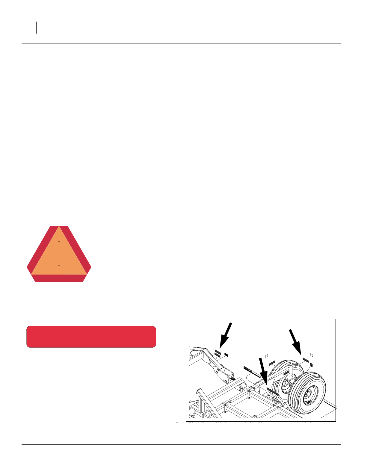
Safety Decals
Safety Reflectors and Decals
Your implement comes equipped with all lights, safety
reflectors and decals in place. They were designed to
help you safely operate your implement.
▲ Read and follow decal directions.
▲ Keep lights in operating condition.
▲ Keep all safety decals clean and legible.
▲ Replace all damaged or missing decals. Order new decals
from your Great Plains dealer. Refer to this section for
proper decal placement.
▲ When ordering new parts or components, also request cor-
responding safety decals.
To install new decals:
1. Clean the area on which the decal is to be placed.
2. Peel backing from decal. Press firmly on surface,
being careful not to cause air bubbles under decal.
818-055C
Slow Moving Vehicle Reflector
Center of rear frame tube;
1 total
838-266C
Red Reflectors
On each of two spindle tubes of the rear casters,
on rear face of each wing near pivot,
on rear face of rear lift-assist side braces;
6 total
17160
17153
160-269M-A 08/03/2010
Page 11
838-265C
Amber Reflectors
Outside each of two rear lift assist arms,
on front of each wing cylinder lug;
6 total.
7
17153
838-267C
Daytime Reflectors
On rear face of each wing near pivot,
on rear face of rear lift-assist side braces;
4 total
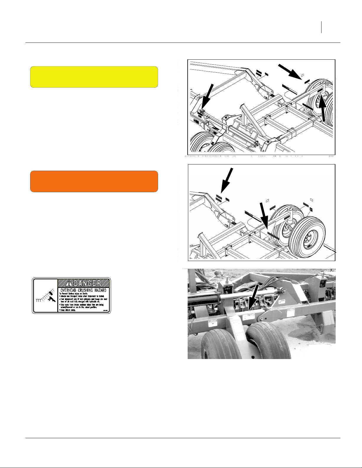
818-046C
Danger: Overhead Crush Hazard
On the front center frame tube, each end;
2 total
17153
17161
08/03/2010 160-269M-A
Page 12

8 CTA4000
818-557C
Danger: Cannot Read English
On the front center frame tube, right of hitch;
1 total
818-624C
17161
Danger: Hitch Crushing Hazard
On top each end of front center frame;
2 total
818-818C
Danger: Electrocution Hazard
One each wing section near fold;
2 total
818-339C
17153
17161
Warning: High Pressure Fluid
On gauge wheel near hydraulics;
1 total
160-269M-A 08/03/2010
17161
Page 13
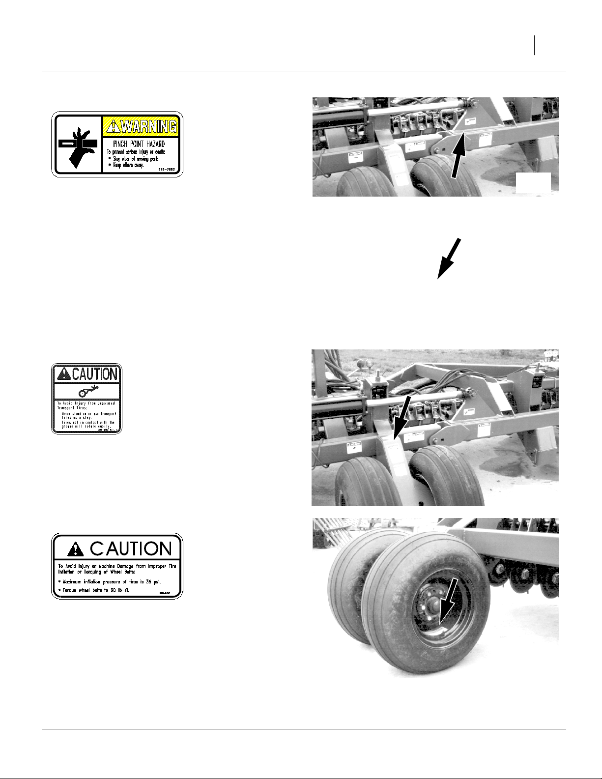
818-798C
9
Warning: Pinch Point Hazard
Fold cylinder mounts, both sides, front and back;
4 total
818-398C
Caution: Tires Not A Step
On each gauge wheel;
6 total
17161
17155
17161
818-855C
Caution: Tire Pressure
On outside rim of each wheel pair;
6 total
17168
08/03/2010 160-269M-A
Page 14
10 CTA4000
Introduction
Great Plains welcomes you to its growing family of new
product owners. Your Air Drill Implement has been
designed with care and built by skilled workers using
quality materials. Proper setup, maintenance, and safe
operating practices will help you get years of satisfactory
use from the machine.
Document Family
160-269M-A Owner’s Manual (this document)
167-085B Seed Rate Charts
160-269P Parts Manual
167-085M Air Cart Operators Manual
Models Covered by this Manual
CTA4000-5010 40 foot, 50 row, 10 inch spacing
CTA4000-6575 40 foot, 65 row, 7.5 inch spacing
CTA4000-8006 40 foot, 80 row, 6 inch spacing
For CTA4000HD, see manual 160-037M.
Description of Unit
The CTA4000 is a pull-type implement for volumetric
seeding. A fan on a companion air cart creates an airflow
to supply seed and dry granular treatments to the implement.
The 2007+ CTA4000 Air Drill Implement is compatible
with the following Great Plains air cart:
• ADC2350 Air Drill Cart,
air cart leading CTA4000 implement
Carts introduced after the release of this manual may
also be compatible. Consult your Great Plains dealer.
For use of the 2006- CTA4000 implement with ADC1150
or ADC2220 air carts, refer to manual:
160-269M Owner’s Manual (pre-2007).
Intended Usage
Use the implement and implement to seed productionagriculture crops only. Do not modify the implement for
use with attachments other than Great Plains options
and accessories specified for use with the implement.
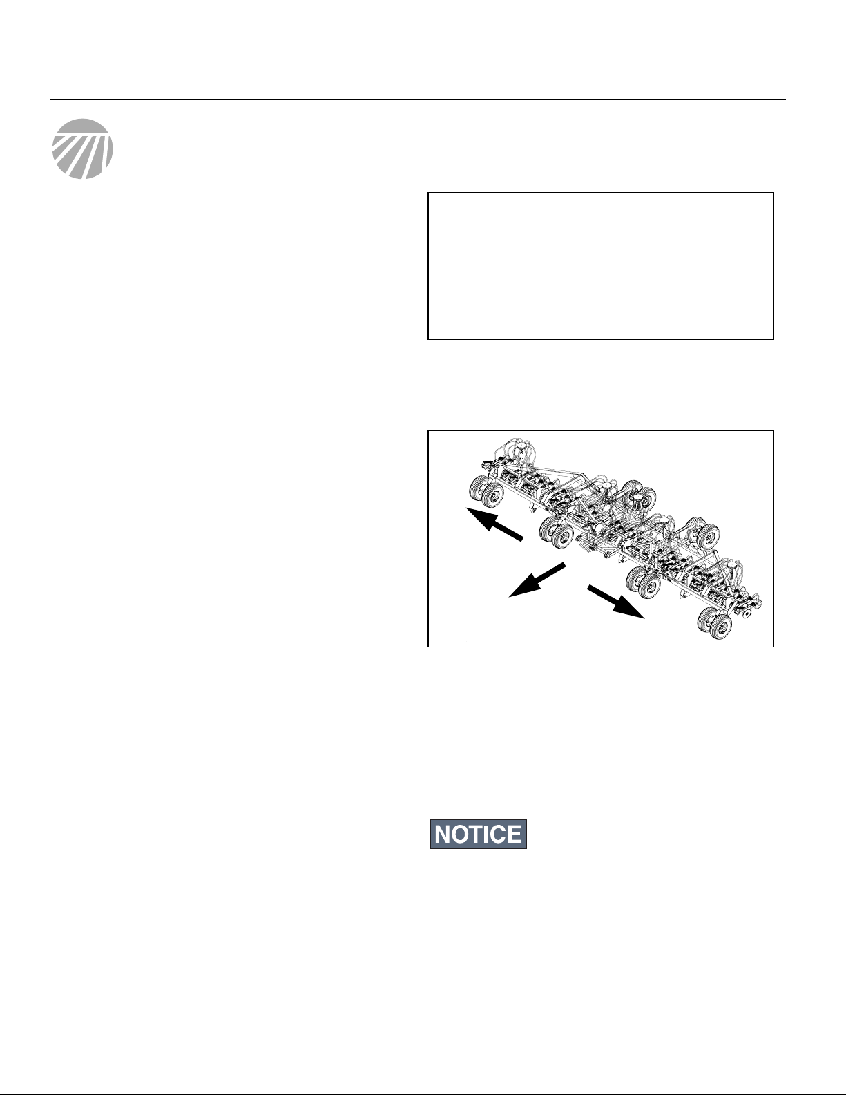
Figure 1
Air Cart Leading Implement
28228
R
L
Figure 2
Left/Right Notation
Definitions
The following terms are used throughout this manual.
Right-hand and left-hand as used in this manual are
determined by facing the direction the machine will travel
while in use unless otherwise stated.
Paragraphs in this format present a crucial point of information
related to the current topic.
26254
Read and follow the directions to:
- remain safe,
- avoid serious damage to equipment and
- ensure desired field results.
Note: Paragraphs in this format provide useful informa-
tion related to the current topic.
160-269M-A 08/03/2010
Page 15

Using This Manual
This manual will familiarize you with safety, assembly,
operation, adjustments, troubleshooting, and maintenance. Read this manual and follow the recommendations to help ensure safe and efficient operation.
The information in this manual is current at printing.
Some parts may change to assure top performance.
Owner Assistance
If you need customer service or repair parts, contact a
Great Plains dealer. They have trained personnel, repair
parts and equipment specially designed for Great Plains
products.
Refer to Figure 3
Your machine’s parts were specially designed and
should only be replaced with Great Plains parts. Always
use the serial and model number when ordering parts
from your Great Plains dealer. The serial-number plate is
located on the left side of the cart frame below the front
hopper.
Record your implement model and serial number here
for quick reference:
Model Number:__________________________
Serial Number: __________________________
Your Great Plains dealer wants you to be satisfied with
your new machine. If you do not understand any part of
this manual or are not satisfied with the service received,
please take the following actions.
1. Discuss the matter with your dealership service
manager. Make sure they are aware of any problems
so they can assist you.
2. If you are still unsatisfied, seek out the owner or general manager of the dealership.
For further assistance write to:
Figure 3
Serial Number Plate
Introduction 11
17160
Product Support
Great Plains Mfg. Inc., Service Department
PO Box 5060
Salina, KS 67402-5060
785-823-3276
08/03/2010 160-269M-A
Page 16
12 CTA4000
Preparation and Setup
This section helps you prepare your tractor, cart and
implement for use. Before using the implement in the
field, you must hitch the implement to a suitable tractor,
compatible cart, and also setup the implement.
Pre-Setup Checklist
1. Read and understand “Important Safety Information” on page 1.
2. Check that all working parts are moving freely, bolts
are tight, and cotter pins are spread.
3. Check that all grease fittings are in place and lubricated. See “Lubrication” on page 51.
4. Check that all safety decals and reflectors are correctly located and legible. Replace if damaged. See
“Safety Decals” on page 6.
5. Inflate tires to pressure recommended and tighten
wheel bolts as specified. “Appendix” on page 55.
Hitching
You may be severely injured or killed by being crushed
between the tractor, cart and implement. Do not stand or place
any part of your body between machines being hitched. Stop
tractor engine and set park brake before installing hitch pins.
When ready for planting, the implement is part of an
assembly that includes the tractor, the cart, and the
implement.
When hitching for the first time, hitch the leading cart to
the tractor first.
Once the cart is hitched to the implement, it is usually left
connected, unless parking or storage considerations
require separation.
This manual includes full details only for the implement’s
hitch. Consult the cart manual for cart-to-tractor hitching.
If the tractor has a load-sensing or constant-flow hydraulic
system, the implement must be equipped with an optional
bypass valve to avoid tractor damage. See “Hydraulic Bypass
Kit” on page 53 for ordering. See “Bleeding Hydraulics” on
page 15 for setup.
Figure 4
Complete Assembly
26360
160-269M-A 08/03/2010
Page 17
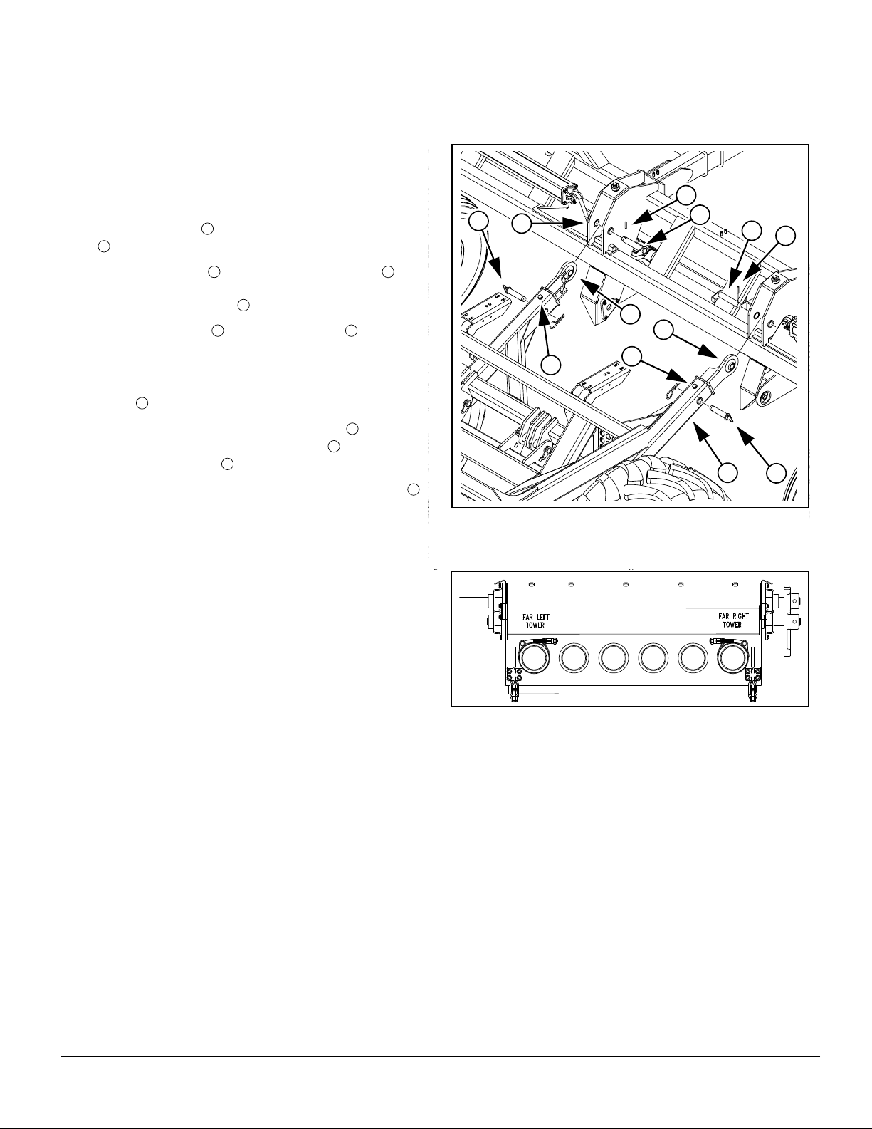
Hitch Link
Refer to Figure 5,
which, for clarity, depicts the air cart without the rear hopper
1. Use a line (not shown), from the cart walkboard, to
tie the cart links up to the height of the lug holes
5
.
1
Preparation and Setup 13
6
2
5
7
7
6
2. Remove the pins near the ball swivel links of
the arms, allowing the arms to telescope. Do not
remove the stop bolts .
3. Drive the roll pins out of the lug pins and
remove the lug pins.
4. Have a tractor slowly guide the cart backwards until
the link arm ball swivels are within two feet of the lug
5
holes in the implement. Set tractor brake.
5. Manually extend each arm’s ball swivel into alignment with the implement pivot holes . Insert and
secure the lug pins on the implement.
6. Slowly back the tractor up until the arm pins may
be reinserted. Secure them with clips.
7. Set tractor parking brake and shut off tractor.
2 3
4
6 7
3
5
7
2
Make Seed Hose Connections
Refer to Figure 6
Connect primary seed hoses (tower feed hoses) from the
implement to their respective outlets on the rear cart
meter box, in left to right order, skipping any capped outlets.
Leave enough slack so that implement can be fully
raised, lowered, folded and unfolded.
Secure hoses to meter box using screw clamps provided.
Orient outer clamps so that they do not interfere with the
door latches on the meter.
3
3
4
Hitching Cart to Implement
Cart Seed Hose Outlets
4
Figure 5
Figure 6
1
2
26431
26302
08/03/2010 160-269M-A
Page 18
14 CTA4000
Make Electrical Connections
Refer to Figure 7
Make sure tractor is shut down with accessory power off
before making connections.
1. Mate the lighting plug to the outlet connector on
the cart.
2. Mate the implement lift switch plug to the outlet
connector on the cart.
3. Mate the seed monitor plug to the outlet connector
on the cart.
4. Secure cables so they are clear of moving parts at
the hitch.
1
2
3
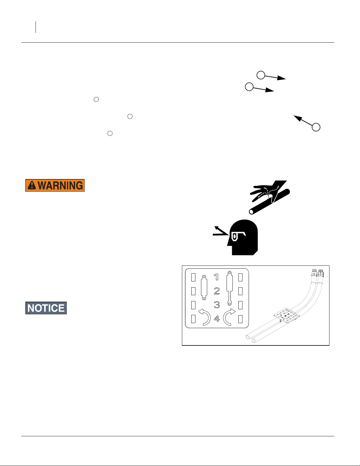
Make Hydraulic Connections
Only trained personnel should work on system hydraulics!
Escaping fluid under pressure can have sufficient pressure to
penetrate the skin, causing serious injury. Avoid the hazard by
relieving pressure before disconnecting hydraulic lines. Use a
piece of paper or cardboard, NOT BODY PARTS, to check for
leaks. Wear protective gloves and safety glasses or goggles
when working with hydraulic systems. If an accident occurs,
seek immediate medical attention from a physician familiar
with this type of injury.
2
3
Figure 7
Lift & Monitor
1
26439
Refer to Figure 8
To distinguish hoses on the same hydraulic circuit, refer
to plastic hose label. The hose under an extended-cylinder symbol feeds a cylinder base end. The hose under a
retracted-cylinder symbol feeds a cylinder rod end.
DO NOT connect the return line to a
power-beyond-port.
Figure 8
Plastic Hose Label
817-348c
17641
160-269M-A 08/03/2010
Page 19
Hydraulic Circuit Connections
The implement has one or two hydraulic circuits (with a
low pressure sump return line). The standard circuit powers lift, fold and weight-transfer functions, controlled by a
valve block on the left front of the implement. An optional
circuit operates the markers.
Great Plains hydraulic hoses are color coded to help you
hookup hoses to your cart outlets. Hoses that go to the
same remote valve are marked with the same color.
Preparation and Setup 15
If the tractor has a load-sensing or constant-flow hydraulic
system, the implement must be equipped with an optional
bypass valve to avoid tractor damage. See “Hydraulic Bypass
Kit” on page 53 for ordering.
1. Shut down tractor hydraulics.
2. If optional markers are already installed, connect
marker hoses to receptacles and per instruc-
A B
tions supplied with markers.
3. Connect the Retract hose of the (blue) Lift/Fold pair
to receptacle .
C
Connect the Extend hose of the (blue) Lower/Unfold
pair to receptacle
4. Skip receptacles and , not used by this imple-
D
E F
ment.
5. Connect the sump hose to receptacle .
G
6. Check hose routing to ensure adequate slack for link
arm movement, and clearance from pinching or
abrading cart/implement components.
Bleeding Hydraulics
To function properly, the hydraulics must be free of air. If
hydraulics have not been bled, they will operate with
jerky, uneven motions and could cause wings to drop
rapidly during folding or unfolding. During initial implement setup (which may have been done by your dealer)
or if you replace a hydraulic component, complete the
following procedures.
Color
Orange
Blue
Yellow
No Color
Cart
Ports
A B
,
C
D
E F
,
G
Hydraulic Function
Markers
(also used for auger on cart)
Lift, Fold and Weight Transfer
Lower, Unfold
(not used on cart)
Not Used by implement
(used for fan on cart)
Sump return
Escaping fluid under pressure can penetrate skin, causing serious injury. Avoid the hazard by relieving pressure before dis-
Figure 9
Levers for Lift Bleed
26372
connecting or “cracking” hydraulic lines. Use a piece of
paper or cardboard, NOT BODY PARTS, to check for leaks.
Wear protective gloves and safety glasses or goggles when
working with hydraulic systems. If an accident occurs, seek
immediate medical attention from a physician familiar with
this type of injury.
08/03/2010 160-269M-A
Page 20
16 CTA4000
Bleed only at
JIC (Joint Industry Conference, 37
NPT (National Pipe Thread, tapered thread) fittings, and
never at
ORB (O-Ring Boss) or
QD (Quick Disconnect) fittings.
° flare) or
Bleeding Lift Hydraulics
1. Check hydraulic fluid level in tractor reservoir and fill
to proper level. Filling a completely empty lift cylinder
set requires about 2 gallons of oil.
1
2
Refer to Figure 9
2. Set valve levers for Field operation.
Refer to Figure 10
3. With implement unfolded, disconnect rod ends of
fold cylinders . Place a support under the cylin-
der end so extending rods will not contact anything.
Note: Although the Fold cylinder valve handle is set to
Field, Fold cylinders may still be activated by the
Weight Transfer circuit.
4. Jack up and support implement frame high enough
so opener cylinders can be fully extended. Use a
jack set rated for the weight of the implement (see
Appendix) plus any optional weights added.
5. Fully extend opener-lift cylinders.
Refer to Figure 11
6. Turn knobs , on pressure-control valves completely counterclockwise, then turn them back far
enough (about three clockwise turns) to build up at
least 1000 psi pressure per gauges , .
1 2
3 4
5 6
Figure 10
Fold Cylinder Supported
4
6
Figure 11
Adjusting for Lift Bleed
16432
5
3
26380
160-269M-A 08/03/2010
Page 21

Refer to Figure 12
7. Loosen JIC hose fittings at locations shown.
8. Slowly engage hydraulic lever, in direction that lowers openers, until oil begins to appear at loosened fittings. Continue engaging lever until all air has been
expelled, then tighten that fitting. Continue to supply
oil until no oil appears at loose fittings when openers
are completely lowered.
9. Slowly engage hydraulic lever in direction that raises
openers until oil begins to appear at loosened fittings. Continue engaging lever until all air is expelled,
then tighten that fitting. Continue to supply oil until no
oil appears at loose fittings when openers are completely raised.
10. Cycle openers up and down about 10 times. Each
time you lower openers, hold tractor remote lever
until opener-lift circuit builds up to pressure set.
Refer to Figure 13
11. Raise openers, and lock them up by turning the
Field/Transport selector valve handle to Transport.
12. Secure the rod cylinder supports and lower the
implement on the jacks.
Note: Leave the fold cylinders disconnected until they are
bled (next section).
Preparation and Setup 17
Figure 13
Post-Bleed Lift Lockup
26373
Figure 12
17154
Lift Bleed Points
08/03/2010 160-269M-A
Page 22

18 CTA4000
Bleeding Fold Hydraulics
Overhead crushing hazard.
To prevent serious injury or death:
▲ Fold implement only if fold hydraulics are bled free of air
and fully charged with hydraulic oil.
▲ Keep away and keep others away when folding or unfolding
implement.
Before folding, you must hitch the implement to the tractor and
cart. Failure to do so could result in severe equipment damage
and bodily injury or death.
1. Check hydraulic-fluid level in tractor reservoir and fill
to proper level. Filling a completely empty fold cylinder set requires about 5 gallons of oil.
Refer to Figure 14
2. If not already done for lift bleeding, with implement
unfolded, disconnect rod ends of fold cylinders .
Place a support under the cylinder end so extend-
2
1
ing rods will not contact anything.
Refer to Figure 15
3. Turn field/folding selector valve to fold position.
4. Loosen rod-end fitting.
5. Slowly engage hydraulic lever as if folding implement
until oil appears at loosened hose fitting. Continue
engaging lever until all air has been expelled from fitting, then tighten fitting.
Figure 14
Fold Cylinder Bleeding
Figure 15
Handles for Fold Bleed
1
2
16432
26375
Refer to Figure 16
6. Loosen fittings of fold cylinder as shown.
7. Slowly engage hydraulic lever, as if unfolding implement, until oil appears at loosened fittings. Continue
engaging lever until all air has been expelled from fitting, then tighten fitting.
8. Cycle fold cylinders in and out 10 times.
9. Re-pin cylinder rods to cylinder mounts.
10. Recheck tractor hydraulic reservoir and fill to proper
level.
11. Slowly fold and unfold implement. Check for hydraulic leaks. Be aware of any pinch points that might
cause damage or accelerate wear on hydraulic
Figure 16
Fold Bleed Points
17199
hoses.
160-269M-A 08/03/2010
Page 23

Load Sensing Setup
To operate the CTA4000, some tractors with load-sensing or constant-flow hydraulics need a bypass valve. See
“Hydraulic Bypass Kit” on page 53 for ordering information. Contact your Great Plains dealer to order the
valve.
Failure to install the bypass valve may cause major tractor
damage. Contact your tractor dealer to verify if the bypass
valve is needed.
Refer to Figure 17
1. After installing the bypass valve , adjust as follows:
2. Loosen lock-ring and completely close off bypass
cross-flow by turning knob fully clockwise.
Refer to Figure 18
3. Set valve levers for Field operation.
4. On tractor, adjust circuit flow-control valve so openers raise and lower at a reasonable speed.
Note: The faster openers raise and lower, the greater po-
tential for oil heating, premature wear or tractor
damage.
5. Engage tractor hydraulics for fan and opener-lift-andfold circuits. Lock hydraulic levers for continuous oil
flow. Make sure cart fan is operating at normal speed
(about 3600 rpm).
2
1
3
Preparation and Setup 19
1
2
3
Figure 17
Optional Bypass Valve
Figure 18
Levers for Bypass Setup
17987
26372
Refer to Figure 19 and Figure 17
6. Adjust wing and center down-pressure-control valves
4 5 6 7
, on implement so gauges , read 1200 psi.
7
6
9
Do not adjust weight-transfer valve at this time. To avoid
implement damage, never set weight-transfer valve above 800
9
psi .
7. While watching opener gauges, slowly adjust bypass
valve knob just until needles on gauges ,
move down from 1200 psi. Lock bypass valve ring
at this setting.
8. Adjust pressure-control valves , to desired
opener down pressure. See “Sub-Frame Down-
Force” on page 37.
08/03/2010 160-269M-A
3 6 7
8
4 5
4
2
8
Figure 19
Pre-Adjusting for Bypass
5
26380
Page 24

20 CTA4000
Eyebolt Adjustment
Refer to Figure 20
Before using the implement, check that the opener
frames are level across the implement. When fully
raised, the top of the opener mounts should clear the
bottom of the top frame tube by at least
(13mm).
Adjust opener frames so all openers have the same
clearance. To raise or lower an opener frame, loosen jam
3 4
nut on opener-lift cylinder and turn adjustment nut .
When openers are at correct height, retighten jam nut.
Repeat for each opener frame if necessary.
2
1
1
⁄
inch
2
1
4
3
2
Figure 20
Opener Height Eyebolt
17159
160-269M-A 08/03/2010
Page 25

Operating Instructions
This section covers general operating procedures. It
assumes that setup items have been completed for both
cart and implement.
Experience, machine familiarity and the following information will lead to efficient operation and good working
habits. Always operate farm machinery with safety in
mind.
General Description
Implement hydraulic functions (except markers) are
routed through a valve block mounted on the left wing.
Once set up, routine implement operations (switching
between folding and lift) require setting valve handles on
this block.
Planting Operation
Via an adjustable implement lift switch on the implement,
the CTA4000 controls the meter drive clutch on the air
cart, turning it on and off as the implement is lowered
and raised.
Seed is delivered to the row units by air, powered by the
fan on the air cart. Seed rate is determined by air cart
setup, and the cart meter rate self-adjusts for changes in
ground speed. Seeding stops when motion stops or the
implement is raised.
The metered seed is carried by air through the hoses to
the distribution towers on the implement. These towers
then divide the air and seed into individual rows.
Seeding depth and furrow coverage are controlled by
implement down pressure and row unit setup.
Operating Instructions 21
Figure 21
Valve Block Location
26377
Pre-Start Checklist
❑ Lubricate the implement as indicated under Lubrica-
tion, “Maintenance and Lubrication” on page 49.
❑ Check the tires for proper inflation according to “Tire
Inflation Chart” on page 55.
❑ Check for worn or damaged parts and repair or
replace before going to the field.
❑ Check all nuts, bolts and screws. Tighten bolts as
specified on “Torque Values Chart” on page 56
❑ Check implement lift switch on implement
❑ Complete all pre-start checklist items on the air cart.
08/03/2010 160-269M-A
Page 26

22 CTA4000
Transport
Electrocution hazard. To prevent serious injury or death from
electric shock, keep clear of overhead power lines when transporting, folding, unfolding or operating all air implement components. Machine is not grounded. At higher voltages,
electrocution can occur without direct contact.
Great Plains recommends transporting the assembly
with cart empty. Although designed for highway movement when loaded, the additional weight of seed may
cause the implement assembly to exceed the rated ability of the tractor, makes the assembly more difficult to
control and stop, and increases wear on cart tires and
wheel bearings.
Use a tractor that weighs at least 2/3 (67%) of the implement plus cart assembly weight (see table below).
A
Towing the implement at high speeds or with a vehicle that is
not heavy enough can lead to loss of vehicle control. Loss of
vehicle control can lead to serious road accidents, injury and
death. To reduce the hazard:
▲ Do not exceed 20 mph (32 kph).
The implement is designed to hitch to a Great Plains air cart
only. Hitching the implement to any vehicle other than a Great
Plains air cart will create an unstable towing load and can
lead to road accidents, injury and death. To avoid the hazard,
transport hitched to a Great Plains air cart.
▲ Do not tow an assembly that weighs more than 1.5 times the
weight of the towing vehicle. (See table below)
CTA4000 No Extra Weights One Weight Kit Two Weight Kits
Rows
ADC2350
Empty
ADC2350
Full
* Figures do not include markers. If near limit, use Appendix data to calculate actual weight of your cart and drill configuration.
6 in
(15.2 cm)
21773 lbs
9876 kg
44173 lbs
20037 kg
7.5 in
(18.9 cm)
20700 lbs
9389 kg
43100 lbs
19550 kg
10 in
(24.8 cm)
19748 lbs
8958 kg
42148 lbs
19118 kg
6 in
(15.2 cm)
23173 lbs
10511 kg
45573 lbs
20672 kg
7.5 in
(18.9 cm)
22100 lbs
10024 kg
44500 lbs
20185 kg
10 in
(24.8 cm)
21148 lbs
9593 kg
43548 lbs
19753 kg
6 in
(15.2 cm)
24573 lbs
11146 kg
46973 lbs
21307 kg
7.5 in
(18.9 cm)
23500 lbs
10659 kg
45900 lbs
20820 kg
10 in
(24.8 cm)
22548 lbs
10228 kg
44948 lbs
20388 kg
160-269M-A 08/03/2010
Page 27

Pre-Transport Checklist
Before transporting the cart, check and observe the following items.
❑ Make sure the weight of the tractor equals or exceeds
the value specified for your air implement assembly.
❑ Air Cart Checklist Complete
Including: cart drive chain locked-out, auger latched,
hopper lids secured, ladders latched up.
❑ Marker Checklist Complete
Markers must be folded or retracted, and may have
transport locks or other transport considerations.
❑ Implement Raised and Locked
Wings locked.
Transport/Field valve handle set to TRANS.
❑ Tires
Check that all tires are properly inflated as listed on
“Tire Inflation Chart” on page 55.
❑ Bystanders
Check that no one is in the way before moving. Do not
allow any one to ride on the cart or implement.
❑ Warning Lights
Always use tractor, cart and implement warning lights
when transporting the air implement.
❑ Clearance
Know the maximum dimensions of the cart and implement in transport position and follow a route that provides adequate clearance from all obstructions,
including overhead lines.
See “Specifications and Capacities” on page 55.
❑ Stopping Distance
Allow sufficient stopping distance and reduce speed
prior to any turns or maneuvers. If the cart is transported full, allow extra stopping distance.
❑ Road Rules
Comply with all national, regional and local laws when
transporting on public roads.
❑ Watch Traffic
The hoppers and implement wings obstruct a portion
of your rear view. Be prepared for sudden maneuvers
from following vehicles.
Operating Instructions 23
Figure 22
Review Transport Checklist
26360
08/03/2010 160-269M-A
Page 28

24 CTA4000
Folding and Unfolding
Fold and unfold implement on level ground. Be aware of
clearance required to fold implement. See “Specifica-
tions and Capacities” on page 55.
Overhead crushing hazard. To prevent serious injury or death:
▲ Always use lock pins when implement is folded.
Electrocution hazard. To prevent serious injury or death from
electric shock, keep clear of overhead power lines when transporting, folding, unfolding or operating all air implement components. Machine is not grounded. At higher voltages,
electrocution can occur without direct contact.
Folding the Implement
Refer to Figure 23
1. If installed, fold the markers1.
2. Set tractor circuits to neutral.
3. Set both valve handles to FIELD.
4. Activate the tractor circuit to raise the openers, and
then set the circuit control to neutral (not float).
Refer to Figure 24
5. Set the Field/Transport valve handle to TRANS. This
hydraulically locks the openers in the raised configuration.
▲ Fold implement only if fold hydraulics are bled free of air
and fully charged with hydraulic oil. See “Bleeding
Hydraulics” on page 15.
▲ Keep away and keep others away when folding or unfolding
implement.
Figure 23
26372
Handles for Pre-Fold Lift
Figure 24
26373
Handles for Pre-Fold Lift-Lock
Refer to Figure 25
6. Turn the Field/Folding valve handle to FOLD.
7. Set tractor at low idle speed.
8. Engage tractor hydraulics and fold implement wings.
Figure 25
26373
Handles for Fold
1 Great Plains does not presently offer markers for the CTA4000.
If installed, consult the documentation provided by the marker supplier.
160-269M-A 08/03/2010
Page 29

Refer to Figure 26
9. Remove the wing lock pin from its storage location
just outboard of the wing hinge point.
Operating Instructions 25
1
Refer to Figure 27
10. Install wing lock pins under hinge points to secure
folded wings for transport or parking.
Figure 26
Wing Lock Pin Stored
2
Figure 27
Wing Locked Up With Pin
17155
17171
08/03/2010 160-269M-A
Page 30

26 CTA4000
Unfolding the Implement
Refer to Figure 28
1. Check that the Transport/Field handle is still set to
TRANS, to keep the opener position locked and prevent unexpected movement during unfold.
Refer to Figure 29
2. Remove wing lock pins under hinge points.
Refer to Figure 26 on page 25.
3. Store pins in storage locations under wing.
Refer to Figure 30
4. Set the Field/Fold valve handle to FOLD.
5. Set tractor at low idle speed.
6. Energize tractor hydraulics and slowly unfold implement.
7. Continue to unfold implement only until each wing
gauge wheel rests on ground, then return hydraulic
lever to neutral.
Figure 28
Unfold: Check Lift-Lock
Figure 29
Unfold: Remove Lock-Up Pins
Figure 30
Unfold: Activate Circuit
26373
17171
26373
Refer to Figure 30
8. When sections are unfolded,
move Field/Fold valve handle to FIELD, and
move Transport/Field handle to FIELD.
Figure 31
26372
Unfold: Completed
160-269M-A 08/03/2010
Page 31

Opener Operation
The hydraulic system places down pressure on the
openers for consistent soil penetration across the implement–even in uneven ground.
Refer to Figure 32
1. Check implement valve handles. Both valve handles
need to be in FIELD position for the hydraulic downpressure and weight-transfer to function.
2. Engage tractor hydraulics for the implement’s lift/fold
circuit. Lock hydraulic lever forward during field operation for constant hydraulic flow to openers.
Tractor-Specific Circuit Operation
John Deere tractors with Sound-Gard ® Body
Use lever lock clip, John Deere part number R52667,
to lock lever forward. See your tractor dealer for clip
purchase and installation.
John Deere 7000 Series tractors
Rotate valve detent selector to motor position to lock
lever in forward position.
John Deere 8000 Series tractors
Set timer to continuous. Push lever forward until
detent clicks.
Case-IH Magnum tractors
Lock lever forward in detent position. You may need
to turn up detent pressure to its maximum setting.
Do not tie hydraulic lever past detent position with a
strap. See your tractor dealer for hydraulic-system
details.
Other Tractors
Lock lever forward in detent position. You may need
to turn up detent pressure to maximum or use a
mechanical detent holder to hold lever forward. See
your tractor dealer for proper means of providing
constant flow to openers.
Operating Instructions 27
Figure 32
Planting: Valve Handles
If the tractor has a load-sensing or constant-flow hydraulic
system, the implement must be equipped with an optional
bypass valve to avoid tractor damage. See “Hydraulic Bypass
Kit” on page 53 for ordering.
26372
Initial Frame Down-Pressure
3
Refer to Figure 33
3. Set opener down pressure. There is one pressurecontrol valve for wing sections and one for center
section .
2
1
2
4
Initially set down pressure at 800 psi, as indicated on
the gauges , . Then adjust as field condition war-
rant.
For more information on adjusting opener hydraulic
down force, refer to See “Sub-Frame Down-Force”
on page 37.
08/03/2010 160-269M-A
3 4
Figure 33
Set Opener Down-Pressure
1
26380
Page 32

28 CTA4000
Initial Seeding Depth
Refer to Figure 34
4. Set opener seeding depth by adjusting press-wheel
height . To adjust, first raise openers slightly, then
lift and slide T handles on top of openers Adjust all
press wheels to the same height.
• For more shallow seeding, slide T handles forward
• For deeper seeding, slide T handles backward
5. While seeding, remember:
• Raise openers before turning. Never back up or
• Be aware of the 5- to 10-foot (1.5-3m) delay
• Check periodically for plugged openers and
You can adjust the opener height at which seed metering
beings. See “Implement Lift Switch Adjustment” on
page 34.
For information on opener adjustments, see “Row Unit
Adjustments” on page 40. For information on troubleshooting opener problems, see “Troubleshooting” on
page 45.
1
2
F
toward implement.
B
away from implement.
turn sharply with openers in the ground. Doing so
will plug openers and may damage equipment.
needed for seed to reach openers. If you stop in
middle of field, lift implement and back up 10 feet
before proceeding.
hoses. With fan running and implement raised,
hand crank metering system. Look below each
opener for seed or fertilizer.
F
1
Figure 34
Initial Opener Depth
2
B
15659
160-269M-A 08/03/2010
Page 33

Fan Speed
This information is repeated from the air cart Operator’s
manual, which has additional guidance.
Fan speed is monitored and reported by the seed monitor, but is manually controlled. The optimum rate
depends on the seed type and treatments. See “Fan
Speed Adjustment” in the cart Operator’s Manual for
further information.Recommended Fan Speeds
Seeds Fan RPM
Operating Instructions 29
Sunflowers
Wheat
Soybeans
Milo
Refer to Figure 35
Open fan shutoff valve for fan operations.
Always engage the fan with the tractor at a low engine speed.
Engaging the fan when the tractor is at high speed may cause
fan damage.
Do not reverse hydraulic flow with the fan running.
The proper reading for the magnehelic air pressure gauge is
12 to 25 inches of water. A sudden drop in pressure is a sign of
a possible leak which can adversely affect seeding.
2,250 - 3,000
3,250 - 4,000
2,750 - 3,500
3,250 - 4,000
Figure 35
Fan Shutoff Valve Open
Figure 36
Fan Air Pressure
26418
26425
Weight Transfer
While seeding, weight is hydraulically transferred from
the center section to the wings so all frame sections run
at the same depth.
This transfer happens automatically whenever the valve
block is set to FIELD operations, and the WT TRANS
valve has been set to any pressure above zero.
If insufficient weight is transferred, the wings will run
higher than the center section. If excess weight is transferred, the center runs higher. To make adjustments, see
“Adjusting Weight Transfer” on page 36.
Handles for Weight Transfer
08/03/2010 160-269M-A
Figure 37
26372
Page 34

30 CTA4000
Marker Operation
Great Plains does not manufacture markers for this
model implement. If you purchased markers, the marker
manufacturer has supplied operating instructions. Carefully read marker manufacturer’s instructions for safe
installation, operation and adjustment. You may also
need the following additional information.
Any markers are on a separate hydraulic circuit on the
implement. The leading air cart has provisions for this
circuit, but also shares the circuit for a cart function.
Markers use hydraulic receptacles and on the air
cart.
Refer to Figure 38
Markers (optional, third-party) share a circuit with the air
cart’s auger, controlled by a two-position selector valve
located at the front right corner of the front bulk hopper
1
on the cart. Handle settings:
2
Back: implement marker circuit enabled;
3
Forward: cart auger circuit enabled
At the implement, markers are typically controlled by a
local automatic sequence valve or solenoid valve (from a
cab switch).
A B
2
Cart Selector Valve
3
Figure 38
1
26417
160-269M-A 08/03/2010
Page 35

Field Operations
This section presumes that all pre-operation check have
been made on both cart and implement, and cart is
loaded with seed and any treatments.
Final Field Checklist
❑ Set seed meters per chart or calibration.
❑ Check cart fan valve set On for fan.
Check cart selector valve set to markers.
❑ Set fan to speed suitable for seed. Watch fan at start-
up to ensure correct direction of rotation.
❑ Run fan for at least 15 minutes before planting.
❑ Check fan air pressure gauge for 12-25 inches of
water pressure.
❑ Check all seed hoses secure.
❑ Check for air leaks at lids and meter box seals.
❑ Implement unfolded.
❑ Implement valve handles set to FIELD.
Operating Instructions 31
Planting Sequence
1. Lower implement 5 to10 feet (1.5-3m) before initial
seeding point.
2. Pull forward and begin planting.
3. Raise implement for turns (meters stop automatically).
Planting
Be aware of the 5 to 10 feet (1.5-3m) of implement-lowered operating distance required for seed to reach the
row units.
If you stop in the middle of a pass, raise the implement
and back up 10 feet (3m) before resumption of seeding.
Seed Monitor
The seed monitor, included with the air cart, performs the
following functions:
On the implement:
• Implement lift switch monitoring
• Seed flow blockage (optional)
• On the Air Cart:
• Fan Speed monitoring
• Hopper material level monitoring
• Hopper air pressure monitoring
• Meter rate monitoring
• Ground speed monitoring
Consult the DICKEY-john manual for how to configure
reporting and alerts.
08/03/2010 160-269M-A
Page 36

32 CTA4000
Parking
Following these steps when parking the implement for
periods of less than 36 hours. For longer periods, see
Storage, the next topic.
1. Spot the implement on firm, level ground.
2. Raise the implement. Fold as necessary for the parking space available.
3. Set the Transport/Field valve handle to TRANS.
4. Perform the air cart parking checklist.
5. Securely block cart tires to prevent rolling.
Storage
If possible, leave the cart and implement connected for
extended storage.
Store the cart and implement where children do not play.
If possible, store them inside for longer life.
1. Perform the cart Storage checklist.
2. Perform the implement Parking checklist.
3. Lubricate the implement at all points listed under
“Lubrication” on page 51.
4. Check all bolts, pins, fittings and hoses. Tighten,
repair or replace parts as needed.
5. Check all moving parts for wear or damage. Make
notes of any parts needing repair before the next
season.
6. Plug or cap seed delivery tubes to prevent pest entry.
7. If the cart is disconnected from the implement for
storage, plug all 2
vent pests from entering and nesting.
8. Use touch-up paint to cover scratches, chips and
worn areas to prevent rust.
1
⁄
-inch (64mm) openings to pre-
2
160-269M-A 08/03/2010
Page 37

Adjustments
Adjustments 33
To get full performance from your implement, you need
an understanding of all component operations, and many
provide adjustments for optimal field results.
The CTA4000 has double-disk openers with depth-controlling press wheels mounted on floating opener frames.
This system provides accurate depth control and seed
placement over uneven terrain. The following is an introduction to the basic seeding components and how they
work.
Each opener is mounted on a floating opener frame.
Opener bodies are staggered for easy soil flow. All openers pivot on a common axis to maintain consistent depth
as the opener frames follow contours. A spring provides
the down pressure necessary for opener double disks to
open a seed furrow. The spring allows openers to float
down into depressions and up over obstructions. Individual openers can be adjusted to account for tire tracks.
Even if your planting conditions rarely change, some of
these adjustment items need periodic attention due to
normal wear.
Planting Depth
Setting nominal planting depth, and achieving it consistently, is affected by multiple adjustable implement functions, from greatest to least effect they are:
• Opener Depth (Press Wheel Height),
• Sub-Frame Down-Force,
• Row Unit Down Pressure (Spring),
• Opener Height,
• Opener-Subframe Adjustment,
• Frame Weight (at higher pressures), and;
• Disk Blade Adjustments (as blades wear).
Adjustment Page The Adjustment Affects
Frame Level 34 Section-to-section planting consistency
Implement Lift Switch Adjustment 34 Avoiding wasted and unplanted seed
Sub-Frame Down-Force 37 Consistent seeding depth
Opener-Subframe Adjustment 39 Level row unit running in desired pressure range
Frame Weight 35 Achieving higher down-force settings
Adjusting Weight Transfer 36 Equal seeding depth under wings and center section
Row Unit Adjustments 40
Opener Height 41 Seeding depth in tire tracks
Row Unit Down Pressure (Spring) 41 Level row unit; consistent seeding depth in tire tracks
Disk Blade Adjustments 42 Consistent seeding depth
Disk Scraper Adjustments 42 Consistent furrow
Seed Firmer Adjustments 43 Consistent seed placement and coverage
Opener Depth (Press Wheel Height) 44 Seeding depth
Fan Speed
*
Consistent seed population and minimum seed damage
29
* See air cart operator’s manual for complete fan information.
08/03/2010 160-269M-A
Page 38

34 CTA4000
Frame Level
Other than “Eyebolt Adjustment” on page 20, there is
no specific setup adjustment for leveling the wings to the
center section. When beginning planting, check frame
level with row units in level ground.
If one or both wings are angled up or down, check and
adjust the following items:
• opener sub-frame adjustment: all gauge wheel trunnions in same frame pivot holes - see “Opener-Sub-
frame Adjustment” on page 39
• weight transfer setting - see “Adjusting Weight
Transfer” on page 36
• opener pivot height: all openers pivoting in same hole
at their mounts (possibly excepting rows in tire tracks)
- see page 41
• opener press wheel height: all row units set the same see page 44
• opener spring down-force: all row units set the same
(possibly excepting rows in tire tracks) - see page 41
Implement Lift Switch Adjustment
Refer to Figure 39
(which, for clarity, depicts the switch region without openers
or gauge wheel)
An implement lift switch on the implement turns seed
metering off when the implement is raised. To adjust the
height at which seed metering is turned off, follow these
steps:
1. Do not place any part of body under implement while
making adjustments.
2. Locate the implement lift switch on the front center
of the mainframe.
3. Raise openers completely and lock them up by set-
ting Transport/Field valve handle to TRANS.
4. Loosen switch mount bolts and slide switch up or
down until actuator makes contact with the lift arm
4
and switch is reliably toggled on (up).
5. Tighten bolts.
Note: Do not set the switch to come on too low. The lift
arm can ride up and down over irregular ground,
and an early switch could result in patches of no
seeding.
If eyebolt adjustment is changed (see page 20), re-check
implement lift switch.
3
1
2
1
4
3
2
Figure 39
Implement Lift Switch
Note: For reference, the ADC2350 lift switch wiring is:
Black (switch COM) to black (extension)
Red (switch N.C.) to red
Green (switch N.O.) not connected
Circuit open when drill is raised
26394
160-269M-A 08/03/2010
Page 39

Frame Weight
The standard CTA4000 includes no additional weights.
Weight kits, consisting of one pair of 700 pound (318kg)
weights (1400 lbs, 635kg, total) are available. The
weights are placed on the center frame. A maximum of 2
pairs (4 weights, 2800 lbs, 1270kg, additional) may be
added.
Extra weights are necessary for opener down-force settings which, when summed for all rows, are near or
above the total weight of the implement. See “Weight
Kits” on page 54.
In unusually soft soil conditions, remove weights to
reduce weight on the tires.
The weights are held in place by gravity, and are easily
removed with a hoist rated for at least 700 pounds
(318kg).
Never add weights to the wings. The weights will tip over during folding. Even if secured to the frame, machine damage is
likely. Wing weights are also unnecessary. The hydraulic
weight transfer system is capable of transferring the entire
weight of the implement to the wings.
Figure 40
Frame Weights
Adjustments 35
16953
Implement Model and Row Spacing
CTA4000-8006
6 in (15.2 cm)
0: Implement without weights 13673 lbs (6202kg) 12660 lbs (5742kg) 11648 lbs (8283kg)
0: Maximum Down Force Per Row 171 lbs (78kg) 195 lbs (88kg) 233 lbs (106kg)
2: Implement with 1 Weight Kit 15073 lbs (6837kg) 14060 lbs (6378kg) 13048 (5918kg)
2: Maximum Down Force Per Row 188 lbs (85kg) 216 lbs (98kg) 261 lbs (118kg)
4: Implement with 2 Weight Kits 16473 lbs (7472kg) 15460 lbs (7013kg) 14448 lbs (6554kg)
4: Maximum Down Force Per Row 206 lbs (93kg) 238 lbs (108kg) 289 lbs (131kg)
CTA4000-6575
7.5 in (18.9 cm)
CTA4000-5010
10 in (24.8 cm)
08/03/2010 160-269M-A
Page 40

36 CTA4000
Adjusting Weight Transfer
Before making adjustments, observe the results of planting at the initial settings suggested in “Weight Transfer”
on page 29.
Refer to Figure 41
The amount of weight transferred to the wings is set by
the “WT TRANS” valve on the implement’s valve block.
To make adjustments:
1. Check that both selector valve handles are set to
FIELD position.
2. Lower openers to ground and leave hydraulics active
and implement circuit engaged as for planting.
Figure 41
Enable Transfer Adjust
26372
3. Release lock ring on WT TRANS control knob.
4. Watch pressure gauge while turning pressure-
control valve knob . When facing the valve, turn
1
2
3
knob clockwise to increase weight on wing sections,
and counterclockwise to decrease weight on wings
sections.
Note: Typical pressures on gauge should be 200 to
2
600 psi.
5. When satisfied with planting depth, wing level and
gauge reading, raise openers while watching pressure gauge. Gauge reading should drop as the
openers are raised.
6. Secure lock ring on WT TRANS control knob.
1
2
1
3
Figure 42
Adjusting Weight Transfer
26437
160-269M-A 08/03/2010
Page 41

Sub-Frame Down-Force
Opener down pressure controls opener penetration and
press-wheel soil firming. Use only enough down pressure to cut the furrow and maintain proper soil-firming
over seed. Excessive opener down force will lead to premature wear on opener components.
Some tractors with load-sensing or constant-flow hydraulics
need a bypass valve with the CTA4000. “Hydraulic Bypass
Kit” on page 53. Before adjusting opener down pressure, set
bypass valve per “Bleeding Hydraulics” on page 15.
Hydraulic Down Pressure
Refer to Figure 43 and Figure 44
Both valve block handles must be set for FIELD for down
force adjustments.
Figure 43
Down Force Valves
2
Adjustments 37
26372
1
There is one pressure-control valve for wing sections
and one for center section .
With hydraulic power to the implement, release the lockrings, and rotate the knobs to adjust pressure, while
watching the readings on the gauges. Rotating the knob
clockwise increases pressure.
Set opener down pressure to 800 psi as a general starting point. For most field conditions, adjust the hydraulic
down pressure between 200 and 1200 psi.
For pressures at and above 1200 psi, make sure implement has enough weight available per opener. see
“Frame Weight” on page 35.
For pressures above 1200 psi, see “Opener-Subframe
Adjustment” on page 39.
Do not set opener down pressure above 1600 psi.
Refer to the chart on the next page for approximate force
at the openers for a given control-valve setting.
2
1
2
Figure 44
Adjusting Frame Down Force
Note: You can set center section pressure slightly higher
than wing pressure, to account for soil compaction
from tractor, cart and implement.
1
26437
08/03/2010 160-269M-A
Page 42

38 CTA4000
Opener Down Force
CTA4000 Row Spacings
Valve 6 in (15.2 cm) 7.5 in (18.9 cm) 10 in (24.8 cm)
200 psi
300 psi
400 psi
500 psi
600 psi
700 psi
800 psi
900 psi
1000 psi
1100 psi
1200 psi
87 lbs (39 kg) 92 lbs (42 kg) 99 lbs (45 kg
96 lbs (44 kg) 103 lbs (47 kg) 113 lbs (51 kg)
105 lbs (48 kg) 113 lbs (51 kg) 128 lbs (58 kg)
113 lbs (51 kg) 124 lbs (56 kg) 142 lbs (64 kg)
122 lbs (55 kg 135 lbs (61 kg) 157 lbs (71 kg)
131 lbs (59 kg) 146 lbs (66 kg) 171 lbs (78 kg)
140 lbs (64 kg) 157 lbs (71 kg) 186 lbs (84 kg)
148 lbs (67 kg) 168 lbs (76 kg) 200 lbs (91 kg)
157 lbs (71 kg) 178 lbs (81 kg) 214 lbs (97 kg)
165 lbs (75 kg) 189 lbs (86 kg) 229 lbs (104 kg)
174 lbs (79 kg) 200 lbs (91 kg) 243 lbs (110 kg)
1 1 1
Down-force settings above 1200 PSI require an adjustment to the opener-subframe arms. See next page.
1300 psi
1400 psi
1500 psi
1600 psi
1700 psi
1800 psi
179 lbs (81 kg) 205 lbs (93 kg) 250 lbs (113 kg)
185 lbs (84 kg) 213 lbs (97 kg) 258 lbs (117 kg)
189 lbs (86 kg) 217 lbs (98 kg) 264 lbs (120 kg)
195 lbs (88 kg) 224 lbs (102 kg) 273 lbs (124 kg)
1 1 1
1 1 1
2 2 2
2 2 2
Not Recommended - likely to
lift gauge wheels off ground
Noted row unit down force figures require additional weight,
unless markers are installed.
1
One weight kit required.
2
Two weight kits required.
160-269M-A 08/03/2010
Page 43

Opener-Subframe Adjustment
At higher down-pressures (above 1200 psi), the row units
can tend to tip forward. An adjustment to the mainframe/
subframe pivot corrects this.
Refer to Figure 45 and Figure 46
The opener tool bar is supported entirely by eight
2 3
arms at the lift cylinders (not shown). The trunnion
at the arm end is connected to the tool bar by a lower
pivot bolt which is never moved.
The arm-tool bar angle is controlled by an upper adjustment bolt , which occupies one of two positions.
• For low-to-1200 psi down pressures, the adjustment
bolt occupies the middle hole of the frame mount
and trunnion.
• Above 1200, the adjustment bolt occupies the top hole
6
Set all arms the same.
To change the bolts (to high pressure):
1. Have a jack at hand.
4
5
of the frame mount and trunnion.
1
5
Adjustments 39
5
1
4
Standard Down Force
(below 1200 psi)
3
Figure 45
2
26383
6
2. Loosen the nuts on all the top bolts .
3. Lower the opener sub-frames.
4. Leave the valve handles set to FIELD.
5. Put the tractor hydraulic circuit in float.
6. Place jack under an opener tool bar at an arm .
7. Lift the tool bar until the bolt is free.
8. Remove the bolt.
9. Repeat step 6 through step 8 the other arm of the
subframe.
10. Raise the jack until the top holes are aligned.
11. Insert the bolt in the top hole and spin on a nut.
12. Repeat step 6 through step 11 for each sub-frame.
13. Tighten all nuts.
Changing from high to low is similar, except lower the
jack at step 7 and reverse the bolt movement.
5
1
6
1
Figure 46
High Down Force
(above 1200 psi)
26384
08/03/2010 160-269M-A
Page 44

40 CTA4000
Row Unit Adjustments
Refer to Figure 47
(which depicts a row unit fully populated with all optional
accessories supported for use with the CTA4000 implement)
From front to back, a Great Plains 00 Series row unit can
include the following capabilities (some optional):
1. Opener height adjustment: standard
If a few rows need to run deeper, such as in tire
tracks, the arm’s pivot point may be lowered. See
“Opener Height” on page 41.
2. Single Down Pressure Spring: standard
Each row unit is mounted on the implement as a pivoting arm which allows the row unit to independently
move up and down. The adjustable spring provides
the force to get the row unit and attachments into the
soil. See “Row Unit Down Pressure (Spring)” on
page 41.
3. Disc Blades: standard, 2 per row unit
Double disc blades open a furrow, creating the seed
bed. Spacers adjust the blades for a clean furrow.
See “Disk Blade Adjustments” on page 42.
4. Seed delivery tube: standard
No adjustments are necessary.
5. Disk Scraper: standard
In sticky soils, a scraper helps keep the opener disks
operating freely. See “Disk Scraper Adjustments”
on page 42.
6. Seed firmer: seed flap (not shown) standard:
2
4
5
7
7
1
3
Figure 47
00 Series Row Unit
6
26382
Keeton seed firmer (not shown)
Improves seed-soil contact, and provides a stable
arm for a low-rate liquid fertilizer delivery tube. See
See “Keeton Seed Firmer Adjustment” on
page 43.
Seed-Lok™ firming wheel (shown)
Improves seed-soil contact. See “Seed-Lok™ Seed
Firmer Lock-Up” on page 43.
7. Press wheels: standard (choice of types)
These close the seed trench. The wheels also support the free end of the row unit, and provide the primary control over seeding depth. See “Opener
Depth (Press Wheel Height)” on page 44.
Do not back up with row units in the ground. To do so will
cause severe damage and row unit plugging.
160-269M-A 08/03/2010
Page 45

Opener Height
The depth to which the opener disk blades penetrate
the soil is controlled in front by the tool bar and pivot
(opener height), and in the back by the press wheel
height.
If the actual ground level is lower for some rows, such
as those in tire tracks, you can lower that row unit by
lowering the pivot point.
Adjustments 41
3
1
Refer to Figure 48
1. Raise the implement just enough to relieve tension
in the down-pressure spring.
2. Remove the bolt from the upper hole .
3. Re-position the arm at the lower hole , and
1
2
secure with bolt.
Note: No spring tension or position adjustment is re-
quired. The pivot holes are designed for neutral
effect on spring tension. The bolt at the top end of
the spring uses a hole that depends on spring
length, and not opener height.
Row Unit Down Pressure (Spring)
For planting in tire tracks, and no-till conditions, you can
increase spring pressure on individual or on all openers.
Adjust the spring in conjunction with the subframe downforce, and opener height, to keep the top of the row unit
parallel to the ground.
Refer to Figure 49 and Figure 50
To increase spring pressure:
1. Loosen jam nut at lower end of opener spring.
2. Tighten flange against spring tension.
Note: Each
1
⁄
4
force at opener disk (approximately 9 kg per cm).
Do not tighten nut more than one inch (2.5 cm).
3. After adjusting, lock flange nut in place with jam nut.
1
inch adjustment adds about 13 pounds of
2
Figure 48
Pivot Point Bolt Holes
26382
1
Figure 49
Row Unit Spring Tension
17158
The length of the spring is factory-set to:
5
13
⁄
16
2
in (33.8cm).
2
4
The reference points for this length are the
center of the upper/front clevis pin and
the base of the lower/rear spring stop cup .
3
4
The factory preset length is recommended for conventional till and min-till conditions. Shorten it for rows in tire
tracks or more difficult min-till conditions. The minimum
recommended length is:
5
12
⁄
in (31.3cm).
16
08/03/2010 160-269M-A
3
Figure 50
00 Series Spring Length
26454
Page 46

42 CTA4000
Disk Blade Adjustments
Opener disc angle and stagger is not adjustable, but
disc-to-disc spacing is, and may need attention as discs
experience normal wear. Spacers will need to be reset
when blades are replaced.
Refer to Figure 51
The ideal spacing causes the blades to be in contact for
about one inch. If you insert two pieces of paper between
the blades, the gap between them should be 0 to 1.75in
(0-4.4cm).
If the contact region is significantly larger or smaller (or
there is no contact at all), it needs to be adjusted by moving one or more spacer washers. If the contact region
varies with blade rotation, one or both blades is likely
bent and in need of replacement.
Adjusting Disc Contact
Figure 51
Checking Disk Contact
26451
Row unit disk blades may be sharp. Use caution when making
adjustments in this area.
Refer to Figure 52
1. Raise the implement and lock it up by moving the
Transport/Field handle to TRANS.
2. Remove the bolt retaining the opener disc on one
side. Carefully remove the disc, noting how many
spacers are outside the disk and inside the disk. Do
not lose the hub components and spacer washers.
3. To reduce the spacing between the discs (the normal
case), move one spacer washer from the inside to
the outside of the disc.
4. Re-assemble and check disc contact.
Disk Scraper Adjustments
To keep opener disks turning freely, dirt scrapers are
mounted between disks to clean as disks rotate. Standard 00 Series row units include a double-disk slotted
scraper.
Refer to Figure 53
As field conditions vary, scrapers may need to be
adjusted. In damp conditions, lower scrapers. If openers
are not turning freely, raise scrapers. To adjust, loosen
bolt and move scraper as needed.
2
1
3
3
3
3
Figure 52
Adjusting Disk Spacers
26385
Row unit disk blades may be sharp. Use caution when making
adjustments in this area.
160-269M-A 08/03/2010
Figure 53
Opener Disk Scraper
16163
Page 47

Seed Firmer Adjustments
00 Series row units include a seed flap, and accept one
of two optional seed firmers.
The seed flap requires no adjustment, but may need to
be replaced if worn, and may need to be shortened if an
optional seed firmer is added after initial delivery.
Row unit disk blades may be sharp. Use caution when making
adjustments in this area.To adjust the Keeton Seed Firmer,
lower the implement until the disks of the row units are resting
on the ground.
Keeton Seed Firmer Adjustment
The optional Keeton Seed Firmer is an engineered polymer shape that slides down the seed trench. It traps
seeds as they exit the seed tube and firms them into the
bottom of the “V”.
Refer to Figure 54
Adjustments 43
1
The Firmer is provided with a preset tension which is recommended for using the first year. The tension screw
can be tightened in subsequent years according to your
needs. Firmers should provide just enough tension to
push seeds to the bottom of the trench.
Seed-Lok™ Seed Firmer Lock-Up
Optional Seed-Lok firming wheels provide additional
seed-to-soil contact. The wheels are spring loaded and
do not require adjusting. In some wet and sticky conditions the wheels may accumulate soil. To avoid problems
associated with this, you can lock-up the firmers.
Refer to Figure 55 (shown with an opener disk removed for
clarity - this task can be performed with disks mounted)
To lock up Seed-Lock wheels:
1. Pull catch wire aside .
2. Pull firming-wheel arm up and release wire to
catch arm.
1
2
1
Figure 54
Keeton Seed Firmer
Figure 55
Seed-Lok™ Lock-Up
26390
1
2
27122
08/03/2010 160-269M-A
Page 48

44 CTA4000
Opener Depth (Press Wheel Height)
Refer to Figure 56
Set opener seeding depth by adjusting press-wheel
height .
1
To adjust, first raise openers slightly, then lift and slide T
handles on top of openers Adjust all press wheels to
2
the same height.
• For more shallow seeding, slide T handles forward
F
toward implement.
• For deeper seeding, slide T handles backward
B
away from implement.
If press wheels are lifting off ground, increase hydraulic
down pressure.
If press wheels are digging into ground, reduce hydraulic
down pressure.
F
1
Figure 56
Adjusting Opener Depth
2
B
15659
160-269M-A 08/03/2010
Page 49

Troubleshooting
Troubleshooting 45
This chart primarily covers problems arising from implement issues, although it does include a few cart items.
Problem Cause Solution
Planting too little
Planting too much
Air leaks Check hopper lids, meter seals, manifold caps
Fan speed too low See “Fan speed is monitored and reported
Implement lift switch engaging too
high
Excessive field speed Reduce speed
Excessive gaps between implement passes
Actual field size is different Verify field size.
Plugged seed hose Clean out seed tube hose.
Plugged opener seed tube Lift up implement, expose bottom of seed tube
Obstruction in meter or seed
tubes (foreign material or
uncleaned seed)
Meter setting too high Re-check against chart & calibration.
Actual field size is different Verify field size.
Excessive overlap or irregular
shaped field
Also consult the Troubleshooting chart for the cart.
and seed hose connections. Adjust latch and/
or replace seals as needed.
by the seed monitor, but is manually controlled. The optimum rate depends on the
seed type and treatments. See “Fan Speed
Adjustment” in the cart Operator’s Manual
for further information.Recommended Fan
Speeds” on page 29.
See “Implement Lift Switch Adjustment” on
page 34.
Adjust markers.
Remove excess slack in hoses.
Re-route hoses to avoid sharp bends.
Check that metering is actually stopping when
implement is raised. Adjust or replace implement lift switch.
and clean out.
Clean meter and seed tube.
Adjust marker.
08/03/2010 160-269M-A
Page 50

46 CTA4000
Problem Cause Solution
Seed visible on ground
behind implement
Seed flow doesn’t stop
during turns
No Seed Flow
Uneven seed spacing or
uneven stand
Seed depth too shallow Check and reset press wheel depth, then
down-forces.
Down force too low Check settings and hydraulics.
Fan speed too high Check rpm on seed monitor.
Ground speed too high Reduce ground speed.
Openers plugging Check disk spacing and scrapers.
Seed hose disconnected or leaking seed.
Meter door open on air cart Clean seals and close door.
Implement lift switch out of adjustment or failed
Implement lift switch out of adjustment or failed.
Cart clutch failed Replace clutch. On an emergency basis, use
Cart clutch circuit failed Replace failed component or cable. On an
Seed rate set to zero Check seed rate indicator at cart meter(s).
Excessive field speed Reduce speed.
Opener disks slowing Check that disks turn freely. Check scrapers.
Insufficient down force for low
spots
Frame not following terrain Hydraulic circuit not locked on.
Air leaks Check hopper lids, meter seals, manifold caps
Erratic meter clutch Check for damaged cables and loose connec-
Tower blockage Check towers for obstructions and plugging.
Seed hose plugged Stop and raise implement with fan running.
Unclean seed Use clean seed.
Seed sticking to firmer Lock-up firmer or wait for drier conditions.
Reconnect or make repairs.
Check latches for proper operation.
Check implement lift switch engagement.
Check, adjust or replace implement lift switch.
the clutch lock-up procedure in the cart Operator’s Manual.
emergency basis, use the clutch lock-up procedure in the cart Operator’s Manual.
Increase down force
and seed hose connections. Adjust latch and/
or replace seals as needed.
tions.
Blockages sometimes move from port to port
in towers.
Hand-crank meter and check for rows not
delivering seed.
160-269M-A 08/03/2010
Page 51

Troubleshooting 47
Problem Cause Solution
Uneven seed depth
Uneven depth across
implement
Implement height
changing or creeping
Seeding pattern skipping
rows
Primary seed hoses are
plugging
Excessive field speed Slow down. Check Seeding Rate Chart for cor-
rect maximum field speed.
Insufficient down force for low
spots
Openers “diving” during no-till
operations
Implement not level Check:
Planting conditions too wet Wait until drier weather.
Implement not level See “Frame Level” on page 34.
Weight transfer to wings too high
or too low.
Press wheel heights not all the
same
Opener heights not all the same See page 41.
Air in system See “Bleeding Lift Hydraulics” on page 16.
Worn lift components. If a cylinder is leaking oil past a seal, consult
Tractor hydraulic malfunction Confirm by using a different circuit for lift.
Plugged openers Check that disks turn freely. Check scrapers.
Seed hose plugged Stop and raise implement with fan running.
Hose disconnected or leaking Check hose path from front cart meter to row
Seed tube plugged Check for debris and pest nests in tube.
Fan speed too low Increase hydraulic flow to circuit.
Erratic fan speed Observe rpm reported by monitor, then check
Flow not stopping when raised Have observer verify that meter gear rotation
Damaged hoses Inspect and repair as needed.
Sharp bends or too much slack in
hoses
Increase down force
Opener frame adjustment incorrect for down
force range. See “Opener-Subframe Adjust-
ment” on page 39.
“Eyebolt Adjustment” on page 20 and
“Frame Level” on page 34.
Lift cylinders may also need bleeding. See
“Bleeding Lift Hydraulics” on page 16.
See “Adjusting Weight Transfer” on page 36.
Set T-handles the same.
the Parts Manual and replace the seal.
Hand-crank meter and check for rows not
delivering seed.
unit. Check for leaks in hoses.
for oil flow surging by tractor.
ceases when implement is moving while
raised.
Re-route hoses for minimum necessary slack
and no sharp bends.
08/03/2010 160-269M-A
Page 52

48 CTA4000
Problem Cause Solution
Secondary seed hoses
plugging
Openers plugging
Opener disks not turning
freely
Furrow not fully or
consistently closed
Press wheels pressing
too deep
Excessive seed cracking
Gauges reading zero with
implement lowered and
circuit locked on
Fan speed too low Increase hydraulic flow to circuit.
Damaged hoses Inspect and repair as needed.
Debris in seed or hoses Disconnect, inspect and clear.
Sharp bends or too much slack in
hoses
Disks need adjustment See page 42.
Scrapers need adjustment See page 42.
Conditions too damp Wait for drier weather.
Trash or caked mud at hub Inspect and clear. Adjust scraper as needed.
Down force too high or too low Adjust down force and re-check.
Depth too shallow Adjust T-handles after checking down-force.
Failed bearing Replace bearing.
Down force too low or too high for
depth setting
Depth too shallow Adjust T-handles on several rows and re-try.
Press wheels not turning freely See that topic above.
Mud building and releasing from
press wheels
Down force too high Adjust down-force and re-try.
Press wheels not turning Check for trash.
Excessive field speed Slow down. Check Seeding Rate Chart for cor-
Fan speed too high Check fan speed against recommendations on
Dividers missing or damaged in
towers
Unclean seed Use clean seed.
Damaged, old or dry seed Use clean, new seed.
Hydraulic hoses mis-routed Re-check hose connections from tractor,
Re-route hoses for minimum necessary slack
and no sharp bends.
Adjust down-force and re-try.
Adjust scrapers.
Conditions may be too wet for planting.
Check for dried mud at hub.
Check for failed bearing.
rect maximum field speed.
page 29.
Check and replace as needed,
through cart, to implement.
Gauge readings increase
Normal No action required.
when circuit is set to
neutral
Openers raise, but
provide no down-
Hose misconnection Re-check hose connections from tractor,
through cart, to implement.
pressure
160-269M-A 08/03/2010
Page 53

Maintenance and Lubrication
Proper servicing and maintenance is the key to long
implement life. With careful and systematic inspection,
you can avoid costly maintenance, downtime and repair.
Always turn off and remove the tractor key before making
any adjustments or performing any maintenance.
You may be severely injured or killed by being crushed under a
falling implement. Always have frame sufficiently blocked up
when working on, and particularly under implement.
Escaping fluid under pressure can have sufficient pressure to
penetrate the skin. Check all hydraulic lines and fittings before
applying pressure. Fluid escaping from a very small hole can
be almost invisible. Use paper or cardboard, not body parts,
and wear heavy gloves to check for suspected leaks. If an accident occurs, seek immediate medical attention from a physician familiar with this type of injury.
After using implement for several hours, check all bolts to
be sure they are tight.
1. Securely block implement before working on it.
2. Lubricate areas listed under “Lubrication” on page
51.
3. Clean any fittings that do not take grease.
4. Inflate tires as specified on “Tire Inflation Chart”on
page 55.
5. Inspect hydraulic hoses for cuts, cracks and aging.
Check fittings for evidence of leaks.
6. Inspect cart link pins for wear or loosening.
7. Replace any worn, damaged or illegible safety
decals. Order new decals from your Great Plains
dealer. “Safety Decals” on page 6.
Maintenance and Lubrication 49
OFF
08/03/2010 160-269M-A
Page 54

50 CTA4000
Seed Flap Replacement (s/n EE1169-)
Refer to Figure 57
To replace a seed flap use a needle nose or similar
tool and squeeze the tabs together. Pull plastic seed
1 3
flap down out of metal bracket .
If replacing with 817-349C:
Push new seed flap up through metal bracket until
2
tabs on seed flap snap in place.
If replacing with 816-302C:
See seed flap replacement instructions below.
1
2
1 3
Seed Flap Replacement (s/n EE1170+)
Refer to Figure 58
To replace an 816-302C seed flap use a needle nose
pliers or similar tool to grasp “T” top of flap. Pull upward
to pull flap up out of metal bracket .
Push new seed flap down through metal bracket
until flap snaps into place with “T” top resting on top of
bracket.
4 5
4
5
2
2
3
1
Figure 57
817-349C Seed Tube Flap
19398
5
4
Figure 58
816-302C Seed Tube Flap
160-269M-A 08/03/2010
31047
Page 55

Lubrication
Maintenance and Lubrication 51
Multipurpose
spray lube
Multipurpose
grease lube
Fold Pivots
10
1 zerk each of 2 pivots; 2 total
Type of Lubrication: Grease
Quantity: Until grease emerges at pivot ends
Rear Wheel Casters
10
1 zerk each of 2 casters; 2 total
Type of Lubrication: Grease
Quantity: Until grease emerges at top and bottom
Multipurpose
oil lube
17165
Intervals (service hours) at
which lubrication is required
50
17167
Cart Links
10
1 zerk each outside pin,
2 zerks center pin;
4 total
Type of Lubrication: Grease
Quantity: Until grease emerges
17166
08/03/2010 160-269M-A
Page 56

52 CTA4000
Opener Frame Arm Pivots
1 zerk each of 8 pivots;8 total
Type of Lubrication: Grease
Quantity: Until grease emerges
Wheel Bearings
Seasonally
10
17164
2 races each of 10 wheels; 20 total
Type of Lubrication: Grease
Quantity: Repack
26387
160-269M-A 08/03/2010
Page 57

Options
Blockage Detector
The seed monitor supports sensors that monitor for plugging in the one-inch, secondary hoses. The package
includes programmable blockage modules for each tower
and flow sensors for each secondary seed hose. The
blockage modules signal the monitor when flow stops at
a sensor. The monitor then sounds an alarm and identifies the problem hose.
To order blockage sensors, contact your Great Plains
dealer.
Implement, Row Spacing Part Numbers
CTA4000-8006, 6 in (15.2 cm) 168-408A
CTA4000-6575, 7.5 in (18.8 cm) 168-409A
Options 53
16457
CTA4000-5010, 10 in (24.8 cm) 168-410A
Hydraulic Bypass Kit
Description Part Number
Tractor Hydraulic Bypass Kit 810-400C
To operate the CTA4000, some tractors with load-sensing closed-center, or constant-flow hydraulics need a
bypass valve.
Consult your tractor dealer for advice about your specific
tractor model.
See “Bleeding Hydraulics” on page 15 for operating
instructions.
Markers
Markers for this implement model are not provide by
Great Plains, but are available from at least one thirdparty supplier. Consult your Great Plains dealer for a current recommendation of brand and model.
17987
Press Wheels
A variety of single and dual press wheels are available,
as bundle options at the time of initial implement order.
Kits are not presently available to convert these in the
field. Parts may be ordered to do so.
08/03/2010 160-269M-A
Page 58

54 CTA4000
Seed Firmers
The standard CTA4000 includes seed flaps. A choice of
firmers is an option in the product bundles, or may be
field-installed as kits. Only one type of seed firmer may
be installed at the same time.
Seed-Lok® Seed Firmer
Description Part Number
Seed-Lok® kit (shown) (per opener) 122-193K
For operations, see “Seed Firmer Adjustments” on
page 43.
Keeton Seed Firmer
Description Part Number
Keeton seed firmer (per opener) 890-810C
For operations, see “Seed Firmer Adjustments” on
page 43.
26389
26390
Weight Kits
The standard CTA4000 implement includes no additional
weights.
Weight kits are available, each with one pair of 700
pound weights (1400 pounds per kit). These are set on
the center frame. The weight transfer hydraulics distribute this weight to the wings.
The CTA4000 supports a maximum of two weight kits
(2800 additional pounds), for a total maximum of four
700 pound weights.
Description Part Number
Weight Kit (1 pair) 160-233A
See “Frame Weight” on page 35 for a table of total and
per-row weight combinations available.
160-269M-A 08/03/2010
Figure 59
Optional Frame Weight
23241
Page 59

Appendix
Specifications and Capacities
Appendix 55
CTA4000-8006 CTA4000-6575 CTA4000-5010
Tractor Requirements
Weight (without weight kits)
Hydraulic Circuits
Hitch
Transport Width
Operating Width
Swath
Row Count
Opener Travel
Number of Towers
Nominal Row Spacing
Averaged Row Spacing
Transport Height
Operating Height
Length
Overall Length w/ADC2350 Cart
Tire Sizes
300 hp
13,673 lbs (6202 kg) 12,600 lbs (5715kg) 11,648 lbs (5283kg)
3 circuits required, load-sensitive or closed-center 15 to 30 gpm at 2000
psi
dedicated dual-link from leading ADC3250 air cart
18 ft (5.5m)
40 ft (12.2m)
486.5 in (12.357 m) 487.1 in (12.372 m) 487.5 in (12.383 m)
80 65 50
11in (27.9cm)
5 (16 ports per tower) 5 (13 ports per tower) 5 (10 ports per tower)
6 in (15.2 cm) 7.5 in (18.9 cm) 10 in (24.8 cm)
6.08 in (15.45 cm) 7.49 in (19.0 cm) 9.75 in (24.77 cm)
14 ft (4.3m)
(vertical operating clearance is determined by air cart)
13 ft 9 in (4.2m)
30 ft 6 in (9.3m)
11L-15 8-Ply
Tire Inflation Chart
Tire Size Inflation
11L-15 8-Ply
08/03/2010 160-269M-A
36 psi
248 kPa
All tires are warranted by the original manufacturer of the tire.
Tire warranty information is found online at the manufacturer’s websites listed below. For assistance or information,
contact your nearest Authorized Farm Tire Retailer.
Manufacturer Website
Firestone www.firestoneag.com
Gleason www.gleasonwheel.com
Titan www.titan-intl.com
Tire Warranty Information
Page 60

56 CTA4000
Torque Values Chart
Bolt
Size
in-tpi
1
⁄4-20
1
⁄4-28
5
⁄16-18
5
⁄16-24
3
⁄8-16
3
⁄8-24
7
⁄16-14
7
⁄16-20
1
⁄2-13
1
⁄2-20
9
⁄16-12
9
⁄16-18
5
⁄8-11
5
⁄8-18
3
⁄4-10
3
⁄4-16
7
⁄8-9
7
⁄8-14
1-8
1-12
11⁄8-7
11⁄8-12
11⁄4-7
11⁄4-12
13⁄8-6
13⁄8-12
11⁄2-6
11⁄2-12
Bolt Head Identification
Bolt Head Identification
Bolt
Size
Grade 2 Grade 5 Grade 8 Class 5.8 Class 8.8 Class 10.9
1
N-m2ft-lb
7.4 5.6 11 8 16 12
8.5 6 13 10 18 14
15 11 24 17 33 25
17 13 26 19 37 27
27 20 42 31 59 44
31 22 47 35 67 49
43 32 67 49 95 70
49 36 75 55 105 78
66 49 105 76 145 105
75 55 115 85 165 120
95 70 150 110 210 155
105 79 165 120 235 170
130 97 205 150 285 210
150 110 230 170 325 240
235 170 360 265 510 375
260 190 405 295 570 420
225 165 585 430 820 605
250 185 640 475 905 670
340 250 875 645 1230 910
370 275 955 705 1350 995
480 355 1080 795 1750 1290
540 395 1210 890 1960 1440
680 500 1520 1120 2460 1820
750 555 1680 1240 2730 2010
890 655 1990 1470 3230 2380
1010 745 2270 1670 3680 2710
1180 870 2640 1950 4290 3160
1330 980 2970 2190 4820 3560
Torque tolerance + 0%, -15% of torquing values. Unless otherwise specified use torque values listed above.
3
N-m ft-lb N-m ft-lb
mm x pitch
M 5 X 0.8
M 6 X 1
M 8 X 1.25
M 8 X 1
M10 X 1.5
M10 X 0.75
M12 X 1.75
M12 X 1.5
M12 X 1
M14 X 2
M14 X 1.5
M16 X 2
M16 X 1.5
M18 X 2.5
M18 X 1.5
M20 X 2.5
M20 X 1.5
M24 X 3
M24 X 2
M30 X 3.5
M30 X 2
M36 X 3.5
M36 X 2
1. in-tpi = nominal thread diameter in inches-threads per inch
2. N· m = newton-meters
3. ft-lb = foot pounds
4. mm x pitch = nominal thread diameter in millimeters x thread
pitch
4
5.8 8.8 10.9
N-m ft-lb N-m ft-lb N-m ft-lb
43659 7
7 5 11 8 15 11
17 12 26 19 36 27
18 13 28 21 39 29
33 24 52 39 72 53
39 29 61 45 85 62
58 42 91 67 125 93
60 44 95 70 130 97
90 66 105 77 145 105
92 68 145 105 200 150
99 73 155 115 215 160
145 105 225 165 315 230
155 115 240 180 335 245
195 145 310 230 405 300
220 165 350 260 485 355
280 205 440 325 610 450
310 230 650 480 900 665
480 355 760 560 1050 780
525 390 830 610 1150 845
960 705 1510 1120 2100 1550
1060 785 1680 1240 2320 1710
1730 1270 2650 1950 3660 2700
1880 1380 2960 2190 4100 3220
25199
160-269M-A 08/03/2010
Page 61

Hydraulic Diagram
Appendix 57
17203
CTA4000 Hydraulic Circuit Assignments
Used With Blue Orange Yellow Black
ADC2350 Cart
CTA4000 Implement
08/03/2010 160-269M-A
Not Used
C
Lift /Fold
D
Lower /Unfold
Auger
A
Marker
B
Marker
Fan
E
Not Used
F
Not Used
Fan Sump Return
G
Sump Return
Page 62

58 CTA4000
Warranty
Great Plains Manufacturing, Incorporated warrants to the original purchaser that this seeding equipment will be free from defects in material
and workmanship for a period of one year from the date of original purchase when used as intended and under normal service and conditions
for personal use; 90 days for commercial or rental purposes. This Warranty is limited to the replacement of any defective part by Great Plains
Manufacturing, Incorporated and the installation by the dealer of any
such replacement part. Great Plains reserves the right to inspect any
equipment or part which are claimed to have been defective in material
or workmanship.
This Warranty does not apply to any part or product which in Great
Plains’ judgement shall have been misused or damaged by accident or
lack of normal maintenance or care, or which has been repaired or altered in a way which adversely affects its performance or reliability, or
which has been used for a purpose for which the product is not designed. This Warranty shall not apply if the product is towed at a speed
in excess of 20 miles per hour.
Claims under this Warranty must be made to the dealer which originally
sold the product and all warranty adjustments must by made through
such dealer. Great Plains reserves the right to make changes in materials or design of the product at any time without notice.
This Warranty shall not be interpreted to render Great Plains liable for
damages of any kind, direct, consequential, or contingent, to property.
Furthermore, Great Plains shall not be liable for damages resulting from
any cause beyond its reasonable control. This Warranty does not extend to loss of crops, losses caused by harvest delays or any expense
or loss for labor, supplies, rental machinery or for any other reason.
No other warranty of any kind whatsoever, express or implied, is
made with respect to this sale; and all implied warranties of merchantability and fitness for a particular purpose which exceed
the obligations set forth in this written warranty are hereby disclaimed and excluded from this sale.
This Warranty is not valid unless registered with Great Plains Manufacturing, Incorporated within 10 days from the date of original purchase.
160-269M-A 08/03/2010
Page 63

Great Plains Manufacturing, Inc. Index 59
Index
A
accident .......................2, 14, 15, 49
ADC1150 .....................................10
ADC2220 .....................................10
ADC2350 .............10, 22, 34, 55, 57
address ........................................11
air pressure .................................29
auger .................................3, 15, 57
B
ball swivels ..................................13
black ......................................34, 57
bleeding hydraulics ......................15
blockage ......................................53
blue ........................................15, 57
bypass kit ....................................53
bypass valve ........12, 15, 19, 27, 37
C
capacities ....................................55
capped outlets .............................13
cart link ........................................13
Case-IH .......................................27
CAUTION, defined ........................1
checklists
final field ..............................31
maintenance ........................49
parking .................................32
pre-setup .............................12
pre-start ...............................21
pre-transport ........................23
storage .................................32
chemicals ......................................2
children ..........................................3
closed-center ...............................53
color code, hydraulic ...................15
color code, switch ........................34
constant-flow .12, 15, 19, 27, 37, 53
CTA4000 .............10, 22, 35, 38, 57
CTA4000HD ................................10
CTA4000-5010 ................10, 53, 55
CTA4000-6575 ................10, 53, 55
CTA4000-8006 ................10, 53, 55
customer service .........................11
cylinder symbols ..........................14
D
DANGER, defined .........................1
decals ........................................1, 6
Caution
Tire Pressure ......................9
Tires Not A Step ..................9
Danger
Cannot Read English ........... 8
Electrocution Hazard ...........8
Hitch Crushing Hazard ......... 8
Overhead Crush Hazard ......7
Warning
High Pressure Fluid .............8
Pinch Point Hazard .............9
DICKEY-john ............................... 31
disc angle .................................... 42
disc contact .................................42
disc stagger ................................. 42
disposal ......................................... 2
down force .......................27, 37, 41
down pressure .......................27, 37
E
electrical connections .................. 14
electrical lines ................................ 3
electrocution ...................... 3, 22, 24
email ............................................11
eyebolt ...................................20, 34
F
fan ...................................15, 29, 57
fan speed .................................... 29
FIELD ...... 24, 26, 27, 29, 36, 37, 39
fittings .......................................... 16
flap, seed .....................................50
FOLD .....................................24, 26
folding ..........................................24
frame weights .............................. 35
G
gloves ...................................... 2, 14
goggles ..........................................2
green ........................................... 34
H
headphones .................................. 2
hearing protection ......................... 2
high pressure fluids ....................... 2
hitching ........................................ 12
hose label .................................... 14
hydraulic diagram ........................ 57
I
implement lift switch ........ 14, 31, 34
Important!, defined ......................10
J
JIC ............................................... 17
JIC (Joint Industry Conference) .. 16
John Deere ..................................27
Joint Industry Conference ...........16
K
Keeton ................................... 43, 54
L
leaks .................................. 2, 14, 29
left-hand, defined ........................ 10
level, opener frames ................... 20
lever, hydraulic ............................ 27
lighting ......................................... 14
liquid treatments ............................ 2
load-sensing .. 12, 15, 19, 27, 37, 53
lock pins ...................................... 24
lock pin, wing .............................. 25
lock-up, Seed-Lok ....................... 43
lubrication .................................... 51
M
magnehelic .................................. 29
Magnum ...................................... 27
markers ........... 3, 15, 24, 30, 53, 57
meter box .................................... 13
milo ............................................. 29
min-till .......................................... 41
monitor .................................. 14, 31
N
National Pipe Thread .................. 16
noise ............................................. 2
Note, defined ............................... 10
NPT (National Pipe Thread) ........ 16
O
opener height ........................ 20, 41
opener-subframe ......................... 39
opener-subframe arms ................ 38
orange ................................... 15, 57
ORB (O-Ring Boss) .................... 16
O-Ring Boss ................................ 16
overhead electrical lines ............... 3
P
parking ........................................ 32
parts ............................................ 11
phone .......................................... 11
pins, wing lock ............................. 26
planting ....................................... 31
planting depth ............................. 33
plug, lift switch ............................. 14
plug, monitor ............................... 14
power-beyond-port ...................... 14
press wheels ............................... 53
pressure-control valve ........... 27, 37
press-wheel height ................ 28, 44
protective clothing ......................... 2
08/03/2010 160-269M-A
Page 64

60 CTA4000 Great Plains Manufacturing, Inc.
Q
QD (Quick Disconnect) ............... 16
Quick Disconnect ........................ 16
R
receptacles, hydraulic ........... 15, 30
red ............................................... 34
reflectors
amber .................................... 7
daytime .................................. 7
red ......................................... 6
repair ........................................... 11
riders ............................................. 3
right-hand, defined ...................... 10
row unit ....................................... 40
R52667 ....................................... 27
S
safety glasses ............................... 2
Safety Symbol ............................... 1
scrapers ...................................... 42
seed firmers .......................... 43, 54
seed flap ............................... 43, 50
seed hoses .................................. 13
seed monitor ............................... 31
seeding delay ........................ 28, 31
seeding depth ....................... 28, 44
Seed-Lok ............................... 43, 54
serial number .............................. 11
shutoff valve, fan ......................... 29
smoke ........................................... 2
SMV (Slow Moving Vehicle) .......... 6
soil compaction ........................... 37
soybeans ..................................... 29
spacers ....................................... 42
spacing, opener disc ................... 42
specifications .............................. 55
speed limit ............................... 3, 22
spring length ............................... 41
spring, opener ............................. 41
storage ........................................ 32
sump ..................................... 15, 57
sunflowers ................................... 29
support ........................................ 11
switch wiring ............................... 34
symbol, cylinder .......................... 14
symbol, safety ............................... 1
T
T handle ................................ 28, 44
tire tracks .................................... 41
tires ......................................... 4, 55
torque .......................................... 56
tractor weight .............................. 22
TRANS ................ 24, 26, 32, 34, 42
transport ...................................... 22
trunnion ....................................... 39
U
unfolding ............................... 24, 26
W
WARNING, defined ....................... 1
warranty ...................................... 58
weight kits ............................. 38, 54
weight transfer .......... 19, 29, 35, 36
welding .......................................... 4
wheat .......................................... 29
wing lock pin ............................... 25
wing lock pins ............................. 26
WT TRANS ........................... 29, 36
Y
yellow .................................... 15, 57
Numerics
00 Series ..................................... 40
1000 psi ...................................... 16
11L-15 8-Ply ............................... 55
1200 psi .................... 19, 37, 38, 39
122-193K, Seed-Lok ................... 54
13 pounds ....................................41
1600 psi .................................37, 38
160-037M, manual .......................10
160-233A, weights .......................54
160-269M-A, manual ...................10
160-269M, manual .......................10
160-269P, manual .......................10
167-085B, manual .......................10
167-085M, manual .......................10
168-408A, blockage .....................53
168-409A, blockage .....................53
168-410A, blockage .....................53
20 mph .....................................3, 22
200 psi .............................36, 37, 38
2007+ ..........................................10
32 kph ......................................3, 22
3600 rpm .....................................19
600 psi .........................................36
700 pound .............................35, 54
800 psi .............................19, 27, 37
810-400C, bypass kit ...................53
817-348C, label ...........................14
818-046C, decal ............................7
818-055C, SMV .............................6
818-339C, decal ............................8
818-398C, decal ............................9
818-557C, decal ............................8
818-624C, decal ............................8
818-798C, decal ............................9
818-818C, decal ............................8
818-855C, decal ............................9
838-265C, reflector ........................7
838-266C, reflector ........................6
838-267C, reflector ........................7
890-810C, Keeton .......................54
160-269M-A 08/03/2010
Page 65

Page 66

Great Plains Manufacturing, Inc.
Corporate Office: P.O. Box 5060
Salina, Kansas 67402-5060 USA
 Loading...