

Page 1
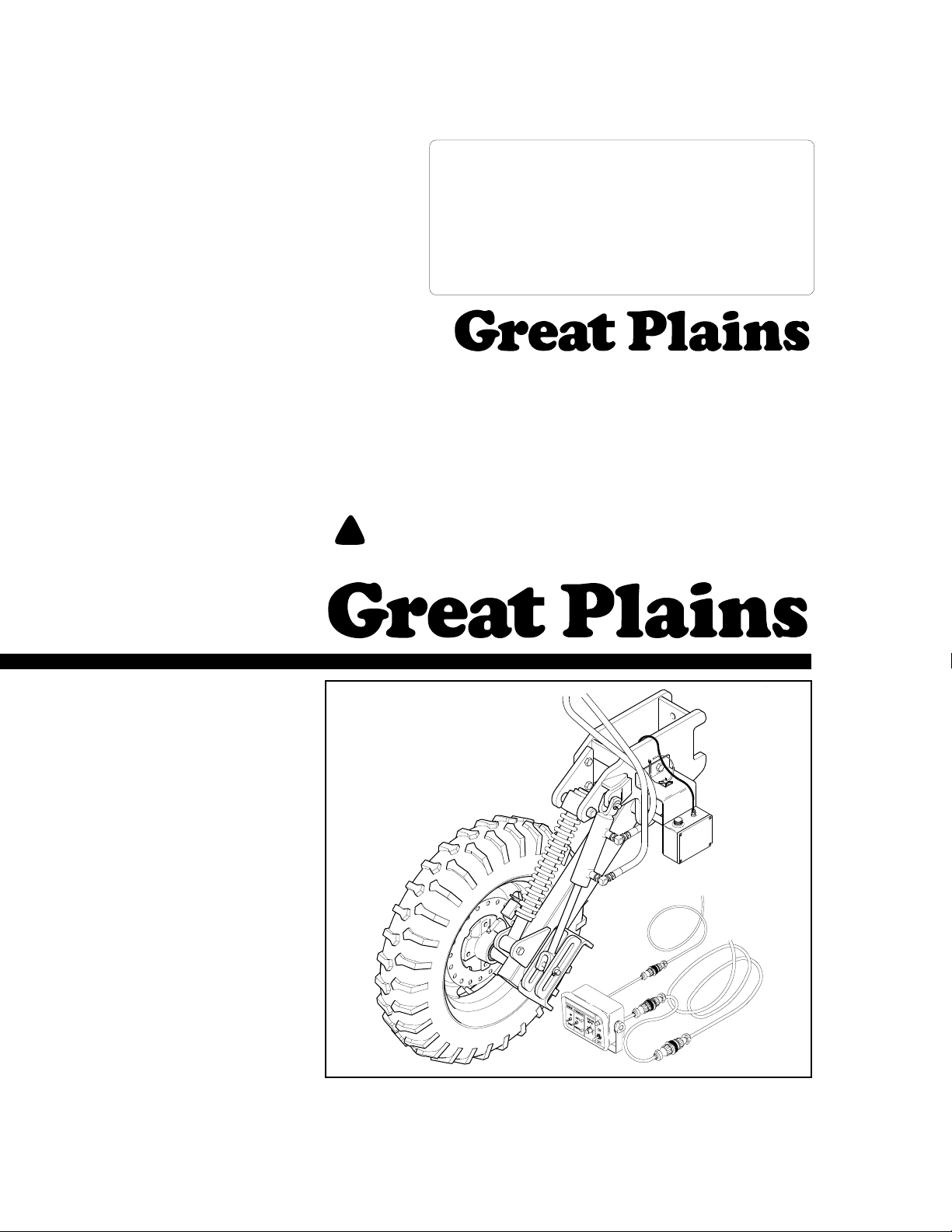
Operator’s/Parts Manual
CPH and CP1000
Coulter Command System
Manufacturing, Inc.
P.O. Box 5060 ● Salina, Kansas 67402-5060
Read the operator’s manual entirely. When you see this symbol, the subsequent in-
!
structions and warnings are serious -follow without exception. Your life and thelivesof
others depend on it!
© Copyright 1999 Printed
2/30/2002
12611
Cover illustration may show optional equipment not supplied with standard unit.
148-258M-B
Page 2

Table of Contents
Table of Contents
Great Plains Mfg., Inc.
Table of Contents . . . . . . . . . . . . . . . . . . . . . . . . . . . 0
Important Safety Information . . . . . . . . . . . . . . . . . 1
Safety Rules. . . . . . . . . . . . . . . . . . . . . . . . . . . . . 1
Introduction. . . . . . . . . . . . . . . . . . . . . . . . . . . . . . . . 2
Product Overview. . . . . . . . . . . . . . . . . . . . . . . . . 2
Using This Manual . . . . . . . . . . . . . . . . . . . . . . . . 2
Definitions . . . . . . . . . . . . . . . . . . . . . . . . . . . 2
Important Notice . . . . . . . . . . . . . . . . . . . . . . 2
Pre-Assembly Checklist. . . . . . . . . . . . . . . . . . . . 3
Coulter Command Assembly . . . . . . . . . . . . . . . . 3
Depth Sensing Wheel . . . . . . . . . . . . . . . . . . 3
Section 1 Assembly Instructions & Set-Up . . . . . . 3
Lift Switch Assembly . . . . . . . . . . . . . . . . . . . 4
Wiring Harness . . . . . . . . . . . . . . . . . . . . . . . 6
Tongue Cylinder. . . . . . . . . . . . . . . . . . . . . . . 7
Hydraulic Control Valve . . . . . . . . . . . . . . . . . 7
Control Box . . . . . . . . . . . . . . . . . . . . . . . . . . 9
Coulter Command Assembly Adjustments. . . . . . 9
Section 2 Operating Instructions . . . . . . . . . . . . . 10
Load Sensing Hydraulics . . . . . . . . . . . . . . . . . . 10
Hydraulic Hook-Up & Function. . . . . . . . . . . . . . 10
Closed-center hydraulic systems . . . . . . . . 10
Open center hydraulic systems. . . . . . . . . . 11
Operation of Electronic Controls . . . . . . . . . . . . 12
Field Adjustments . . . . . . . . . . . . . . . . . . . . . . . 12
Lift Switch. . . . . . . . . . . . . . . . . . . . . . . . . . .12
Speed Sensor. . . . . . . . . . . . . . . . . . . . . . . .13
Hydraulic Valve. . . . . . . . . . . . . . . . . . . . . . .13
Transport Cylinder Depth Channels . . . . . . . 13
Section 3 Troubleshooting . . . . . . . . . . . . . . . . . . . 14
System Schematics . . . . . . . . . . . . . . . . . . . . . .17
Hydraulic Schematic. . . . . . . . . . . . . . . . . . .17
Electrical Schematic. . . . . . . . . . . . . . . . . . .18
Section 4 Maintenance and Lubrication . . . . . . . .19
Maintenance. . . . . . . . . . . . . . . . . . . . . . . . . . . .19
Lubrication . . . . . . . . . . . . . . . . . . . . . . . . . . . . .19
Section 5 Parts . . . . . . . . . . . . . . . . . . . . . . . . . . . . 20
Coulter Depth Control Hydraulics. . . . . . . . . . . .20
Coulter Command Electronics . . . . . . . . . . . . . .22
Coulter Command Gauge Wheel Assembly. . . .24
Top Link Assembly . . . . . . . . . . . . . . . . . . . . . . .26
Coulter Command Switch Mount . . . . . . . . . . . .28
Lift Circuit Manifold (810-262C) . . . . . . . . . . . . .30
Coulter Depth Control Valve (810-214C) . . . . . .32
O-Ring Identification Chart . . . . . . . . . . . . . . . . . 34
Appendix . . . . . . . . . . . . . . . . . . . . . . . . . . . . . . . . .36
Torque Values Chart for Common Bolt Sizes . . .36
Tire Inflation Chart . . . . . . . . . . . . . . . . . . . . . . .36
Warranty. . . . . . . . . . . . . . . . . . . . . . . . . . . . . . .37
CPH and CP1000 Coulter Command System 148-258M-B 9/21/05
0
Page 3

Great Plains Mfg., Inc.
Important Safety Information
Important Safety Information
Foryour safety and to help in developinga better understanding of your equipment we highly recommend that
you read the operator sections of this manual. Reading
these sections not only provides valuable training but
also familiarizes you with helpful information and its location. The parts sections are for reference only and
don’trequire covertocoverreading.Afterreviewingyour
manual store it in a dry,easily accessible location for future reference.
!
The SAFETY ALERT SYMBOL indicates that there is a
potential hazard to personal safety involved and extra
safety precautions must be taken. When you see this
symbol, be alertand carefully read themessage that follows it. In addition to design and configuration of
equipment; hazard control and accident prevention are
dependentupon the awareness,concern,prudence and
proper training of personnel involved in the operation,
transport, maintenance and storage of equipment.
Watchforthe followingsafety notations through-out
your Operators Manual:
!
DANGER!
Indicates an imminently hazardous situation which, if
not avoided, will result in death or serious injury. This
signal word is limited to the most extreme situations.
!
WARNING!
Indicates a potentially hazardoussituation which, if not
avoided, could result in death or serious injury.
1. Escaping fluid under pressure can have sufficient force
to penetrate the skin. Check all hydraulic lines and hoses
before applying pressure. Fluid escaping from a very
small hole can be almost invisible. Use paper or cardboard, not body parts, to check for suspected leaks. If injured, seek medical assistance from a doctor that is
familiar with this type of injury. Foreign fluids in the tissue must be surgically removed within a few hours or
gangrene will result.
2. Make sure all people, animals, and objects are clear of
the coulter tool bar before switching the tongue hydrau-
lics switch to the "auto" mode.
3. Do not crawl under a raised machine without the transport lock blocks securely in place. Sudden hydraulic activation or failure could cause serious injury or death.
4. Never permit anyone to ride on hitch or planting equipment when moving.
5. Never permit anyone to ride tractor when hitch is being
moved.
6. Do not pull the Center Pivot Hitch faster than 20 miles
per hour.
7. Always set the hitch in field position before assembling,
lubrication, making adjustments, or servicing. Periodically check bolts for tightness and lubricate all fittings.
8. Shut off hydraulics valves and shut down tractor before
preforming any maintenance to the hitch or crawling under it.
9. Do not allow anyone to operate the machine who has not
been properly trained in its safe operation.
10. Do not operate equipment while under the influence of
drugs or alcohol.
11. Keep hands, feet, hair, and clothing away from all moving parts.
12. Clear the area of bystanders, especially small children
and animals before moving and operating equipment.
Review the safety instructions annually.
!
Indicates a potentially hazardous situation which, if not
avoided, may result in minor or moderate injury. It may also
be used to alert against unsafe practices.
Safety Rules
Most accidents are the result of negligence and carelessness, usually caused by failure of the operator to
follow simple but necessary safety precautions. The followingsafetyprecautions are suggested to help prevent
such accidents. The safeoperation of any machinery is
a big concern to consumers and manufacturers.Your
Coulter Command System has been designed with
many built-in safety features. However, no one should
operate this product beforecarefully reading this Operator’s Manual.
9/21/05
CAUTION!
CPH and CP1000 Coulter Command System 148-258M-B
1
Page 4

Introduction
Introduction
Great Plains Mfg., Inc.
This manual applies to the following:
148-260A CPH Coulter Command
148-272A CPH Coulter Command Update
148-260A CP1000 Coulter Command
This manual has been prepared to instruct you in the
safe and efficient operation of your Coulter Command
System. Read and follow all instructions and safetyprecautions carefully.
Theparts on yourCoulter Command havebeen specially designed and should only be replaced with genuine
GreatPlains parts. Therefore, should your Coulter Commandrequirereplacement parts go toyourGreat Plains
Dealer.
Product Overview
The Coulter Command couples a microprocessor with
electro-hydraulics to provide a state-of-the-art system
formaintaining coulter depth regardless of the terrain or
soil type. It also provides coulter depth adjustment
"FromThe TractorCab". The Coulter Commandsystem
contains a depth sensing wheel, an electronic control
box, a speed sensor, a depth sensor box, a lift control
switch,a wiringharness, a top link, and a hydraulic control valve. It also uses the tongue cylinder from your
Center Pivot Hitch (CPH) or CP1000.
Definitions
The right hand and left hand as used throughout this
manual is determined by facing in the direction the machine will travel when in use unless otherwise stated.
NOTE: Indicates a special point of information
which requires your attention.
Important Notice
Great Plains Manufacturing, Inc. provides this publication “as is” without warranty of any kind, either
expressed or implied, while every precaution has been
taken in the preparation of this manual, Great Plains
Manufacturing,Inc. assumesno responsibility forerrors
oromissions.Neither is any liability assumed for damages resulting from the use of the information contained
herein. Great Plains Manufacturing, Inc. reserves the
righttoreviseand improveits products asitseesfit.This
publicationdescribes the state ofthisproductat the time
of its publication, and may not reflect the product at all
times in the future.
Printed in the United States of America.
Foryour convenience, record your Serial Number, Mod-
el Number and the Date Purchased in the space
provided below. Have this information before you when
calling a Great Plains Authorized Dealer.
Using This Manual
Foryour safety and to help in developinga better understanding of your equipment we highly recommend that
you read the operator sections of this manual. Reading
these sections not only provides valuable training but
also familiarizes you with helpful information and its location. The parts sections are for reference only and
don’t require cover to cover reading. After reviewing
your manual store it in a dry, easily accessible location
for future reference.
CPH and CP1000 Coulter Command System 148-258M-B 9/21/05
2
Page 5
Great Plains Mfg., Inc.
Section 1 Assembly Instructions & Set-Up
Section 1 Assembly Instructions & Set-Up
Pre-Assembly Checklist
Check
All major components
Fasteners that were shipped with the Coulter Command
System.
NOTE: Some of the hardware from the factory has been
installed in the location where it will be used.
Have a minimum of 2 people at hand while assembling the
Coulter Command.
Have a fork lift or loader along with chains and safety
stands ready for the assembly task.
If you are unsure where a fastener is used, use the parts
section of this manual to identify it. Be sure the part gets
used in the correct location.
Coulter Command Assembly
Depth Sensing Wheel
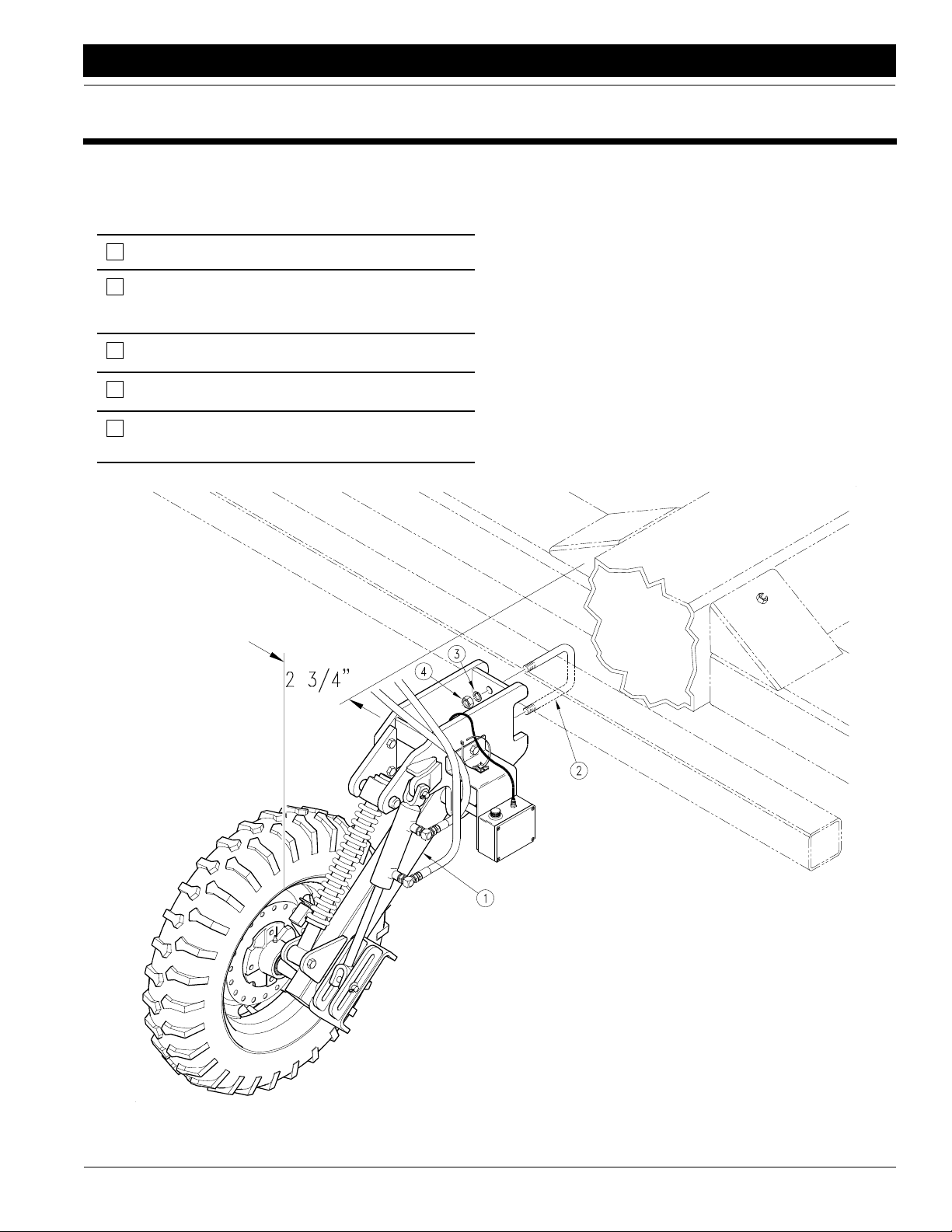
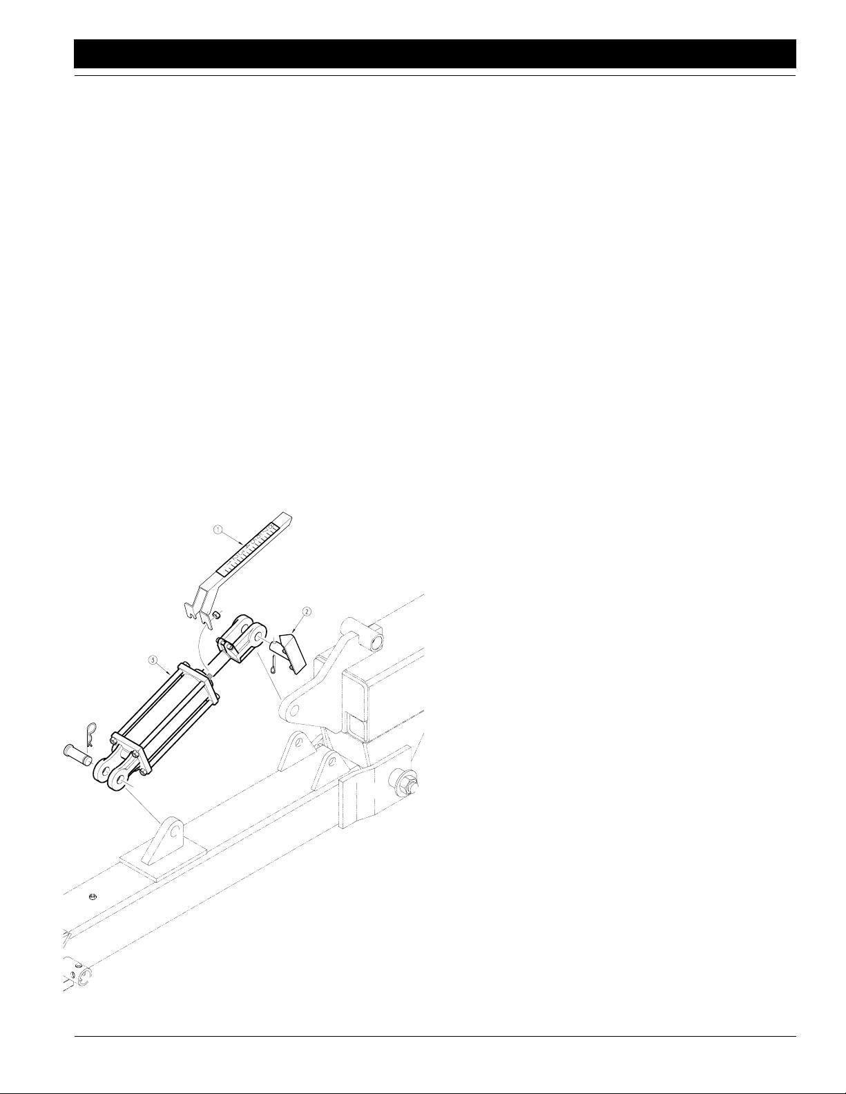
Refer to Figure1
Install the coulter depth sensingwheel assembly (#1) to
the front 4" x 4" coulter tool bar tube with the 5/8" X 6"
long U-bolt (#2), lock washers (#3), and nuts (#4). The
centerofthecoulter depth sensing wheel mount bracket
should be positioned 2 1/4" to the right of the center of
the hitch center beam. This dimension leaves about 2 3/
4"clearance between the inside edge of thedepth sensing tire and the edge of the 8" X 8" hitch center beam.
9/21/05
Figure 1
Coulter Command Assembly
CPH and CP1000 Coulter Command System 148-258M-B
12613
3
Page 6

Section 1 Assembly Instructions & Set-Up
Great Plains Mfg., Inc.
Lift Switch Assembly
Refer to Figure2
1. Remove the 1/2" x 5 1/2" long bolts (#28) nuts, flat
washers, and springs from the right hand transport
cylinderbraceand insert theswitchmount (#4),and
1/2" lock washer (#15), under the head of the bolt.
Position the mount and bolts back onto the brace
and reassemble the nuts, flat washers and springs
onto the brace. It is important that these support
braces are properly assembled to supportthe transport cylinders without binding or placing undo side
loads on the cylinders. Whenever the 5 1/2" support
bolts are removed or the inner axle slide blocks becomeworn, assemble or adjust the cylindersupport
braces as follows.
a. Assemble the 1/2" x 5 1/2" long full thread bolt
(#28), 1/2" lock washer (#15), and the switch
mount (#4) to the cylinder support brace (#22)
bolted to the rod end cylinder casting.
b. Screw on three 1/2" jam nuts (#23), and one
1/2" washer (#24) as shownin . Tighten thefirst
jam nut against the cylinder support (#22) and
run the other two jam nuts on, nearly all the way.
c. With the cylinder properly installed, the support
bolts (#28) should extend through the bracket
(#27)on the outer slide tube when thebaseend
and rod end pins are in place.
d. Screw the outer 1/2" jam nut out until the 1/2"
washer (#24) just touches the bracket on the
outer slide tube. Do not put pressure on the cylinder by tightening the 1/2" jam nut. Once the
washer touches the bracket,lock the outer 1/2"
jam nut in place with the center 1/2" jam nut.
e. Install spring (#25) and 1/2" nylock nut (#26).
Tighten nut to compress spring to a 1 1/4"
length.
Use this procedure foreach of the two supportbolts
on the transport cylinders.
2. Fastenthe cylinder rod clamps (#3 & 6) to the clevis
end of the cylinder rod with two 5/16" x 1 1/4" bolts
(#16),lockwashers(#18)andnuts(#19). The offset
of the clamp must be toward the right hand side of
the hitch as shown.
3. Withthe ramp of thepushrod(#5),facing towardthe
center of the hitch, insert it between the ears of the
cylinder rod clamp (#6), and bolt it in place with a
5/16"x 1 1/4" bolt (#16),two5/16" USS flat washers
(#17), and nylock nut (#20). It is recommended to
bolt it through the lower-most hole in the push rod.
Only run the nylock nut far enough onto the bolt to
makefull engagement of thenylon collar on the nut.
Do not cinch it down. Thebolt and push rod mustbe
free to move in the slot of the clamp.
4. Slide the switch guide block (#2), over the push rod
and fasten it to the mount with two 1/4" x 2" long
bolts (#12), flat washer (#21), lock washers (#13),
and nuts (#14).
5. Bolt the plunger activated switch (#7), to the mount
with the spacer plate (#1), under it with two #10" x
1 1/2" long round head machine screws (#8), flat
washers (#9), lock washers (#10), and nuts (#11).
Slide the plunger switch in the slots of the mount so
the plunger moves "in" about 1/8" when the cam on
the push rod activates it and tighten the screws.Do
not"bottom out" the plunger on theswitchor itcould
be damaged.
Wiring Harness
CPH and CP1000 Coulter Command System 148-258M-B 9/21/05
4
Page 7
Great Plains Mfg., Inc.
Section 1 Assembly Instructions & Set-Up
9/21/05
12612
Figure 2
Switch Assembly
CPH and CP1000 Coulter Command System 148-258M-B
5
Page 8
Section 1 Assembly Instructions & Set-Up
Great Plains Mfg., Inc.
Refer to Figure3
1. Route the 156" long two wire lead of the wiring harness(#1) through the 8" x 8" hitch tube andtothelift
switch(#2) at the rear of the machine. Plug in the lift
switch and support the cable with the cable tie
mounts (#3) and releasable cable ties (#4) or strap
the cable to the hydraulic hoses.
2. Plugthe 4-Pin connector ofthewiringharnesstothe
sensor boxon the depth sensing wheel and support
the cable with the cable tie mounts (#3) and releasable cable ties (#4).
3. Route the 9-Pin connector through the spring hose
loop and to the tractor hitch. This will plug into the 9Pin Female lead from the control box extension cable (#5).
4. The other three short leads on the wiring harness
will plug into the leads from the solenoids on the hydraulic control valves after they are installed.
12617
Figure 3
Wiring Harness Assembly
CPH and CP1000 Coulter Command System 148-258M-B 9/21/05
6
Page 9
Great Plains Mfg., Inc.
Section 1 Assembly Instructions & Set-Up
Tongue Cylinder
Refer to Figure4
1. Remove the stroke pointer gauge (#1) which was
bolted to the rod end of the tongue cylinder and retorque the cylinder tie rod bolts to 95 FT-LBS. Remove the stroke pointer (#2) at the cylinder rod
clevis and discard it.
Refer to Figure5
2. Turn the tongue cylinder with the rod end pointing
forwardand down,andwith the portsturned up. Use
the clevis pin (#17), flat washer (#18), and 1/4" cotterpin(#13) to replace the stroke pointer pin at what
is now the base end of the cylinder. Use the existing
clevis pin (#15) and hair pin cotter (#16) to connect
the rod end to the tongue.
3. Removethe elbow fitting (#3) at the base end of the
tongue cylinder and screw the 1/16" orifice plate
(#9)intothebaseendport. Screw the orifice plate in
far enough so it doesn't interfere with the elbow fitting and replace the fitting.
IMPORTANT: Failureto install the orifice platewill not allow coulter command to operate correctly.
12672
Figure 4
Tongue Cylinder Disassembly
Hydraulic Control Valve
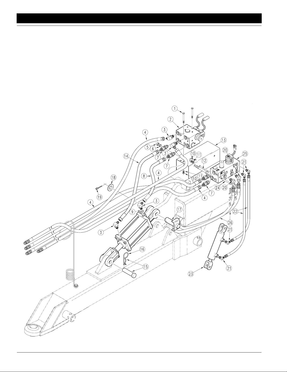
Refer to Figure5
1. Boltthe 3 1/2" x 3 1/2" x 5" hydraulicvalveblock(#2)
to the top of the valve mount bracket (#13) with the
5/16" x 4" long bolts (#1), lock washers (#11), and
hex nuts (#10). Position the valve block so the solenoids set above the middle of the top surface of the
valve mount.
2. Boltthe 3" x 3 1/4" x 8" hydraulic valveblock (#25) to
the side of the valve mount bracket (#13) with the
5/16" x 3 1/2" long bolts (#24), lock washers (#11),
and hex nuts (#10). Positionthe valveblock so the
four ports point awayfrom the valvemount and the
solenoid points up.
3. Bolt the valve mount assembly to the hitch with the
1/2" x 5 1/2" long bolt (#12), lock washer (#6), and
hex nut (#5). Assemble the bolt through the pivot
tube for the levellink located just behind the tongue
cylinder. Position the valve mount so the dual solenoids face toward the rear of the machine.
4. Assemblethe 3/4" JIC elbows (#3) to the valveports
marked"P"and "T" of the top valve block.Assemble
the straight 3/4" adaptors (#7) to the valve ports
marked"A"and"B"of the top valveblock. Assemble
the straight 3/4" adaptors (#7) to the valve ports
marked "V1" and V2" of the lower valve block. Assemble the 1/2" female pipe swivel elbows (#20) to
the valveports marked "C3" and "C4" of the lower
valveblock. Assemble the 9/16" elbows (#21) to the
valveports marked "C1" and "C2" of the lowerblock.
Assemble the remaining two 9/16" elbows (#21) to
the ports on the side of the 1 1/2" x 4" gauge wheel
lift cylinder (#23).
5. Remove the 122" hoses (#4) from the tongue cylinder and assemble them to the elbows (#3) at ports
"P" and "T" on the top hydraulic valve. Connect the
20" long hose (#8) between the port "B" of the top
valveand the tongue cylinder base end fitting. Connect the 30" long hose (#14)betweenport "A"of the
top valve and the tongue cylinder rod end fitting. Assemble the other two 122" hoses (#4), from the
Coulter Command kit, to the adaptors (#7) at ports
"V1" and "V2" on the lower hydraulic valve.Remove
the quick couplers from the ends of the long transport lift hoses (#26) and assemble them to the ends
of the 122" hoses (#4) from ports "V1" and "V2". Assemble the long transport lift hoses (#26) to the elbows (#20) at ports"C3" and "C4" on the lower
hydraulicvalve.The hose coming from the base end
of the transport lift cylinders connects to the port
marked "C3" and the hose coming form the rod end
of the transport lift cylinders connects to the port
marked "C4". Slide the excess hose from the long
transport lift hoses into the 8" x 8" hitch main tube.
Connect one of the 36" long 1/4" hoses (#22) between the port "C1" of the lower valveblock and the
9/21/05
CPH and CP1000 Coulter Command System 148-258M-B
7
Page 10
Section 1 Assembly Instructions & Set-Up
1 1/2" x 4" gauge wheel lift cylinder base and elbow
fitting (#21). Connect the other 36" long 1/4" hose
(#22) between the port"C2" of the lower valve block
and the 1 1/2" x 4" gauge wheel lift cylinder rod end
elbow fitting (#21).
6. Route the three 16" wiring harness leads with the
weather-proof connectors, under the valve mount
and connect each lead to its solenoid. The lead labeled "A" should be plugged into the solenoid
marked"A",Theleadlabeled"B"shouldbeplugged
into the solenoid marked "B," and the lead labeled
"S1" should be plugged into the solenoid marked
"S1."
Great Plains Mfg., Inc.
13482
Figure 5
Hydraulic Control Valve Assembly
CPH and CP1000 Coulter Command System 148-258M-B 9/21/05
8
Page 11
Great Plains Mfg., Inc.
Section 1 Assembly Instructions & Set-Up
Control Box
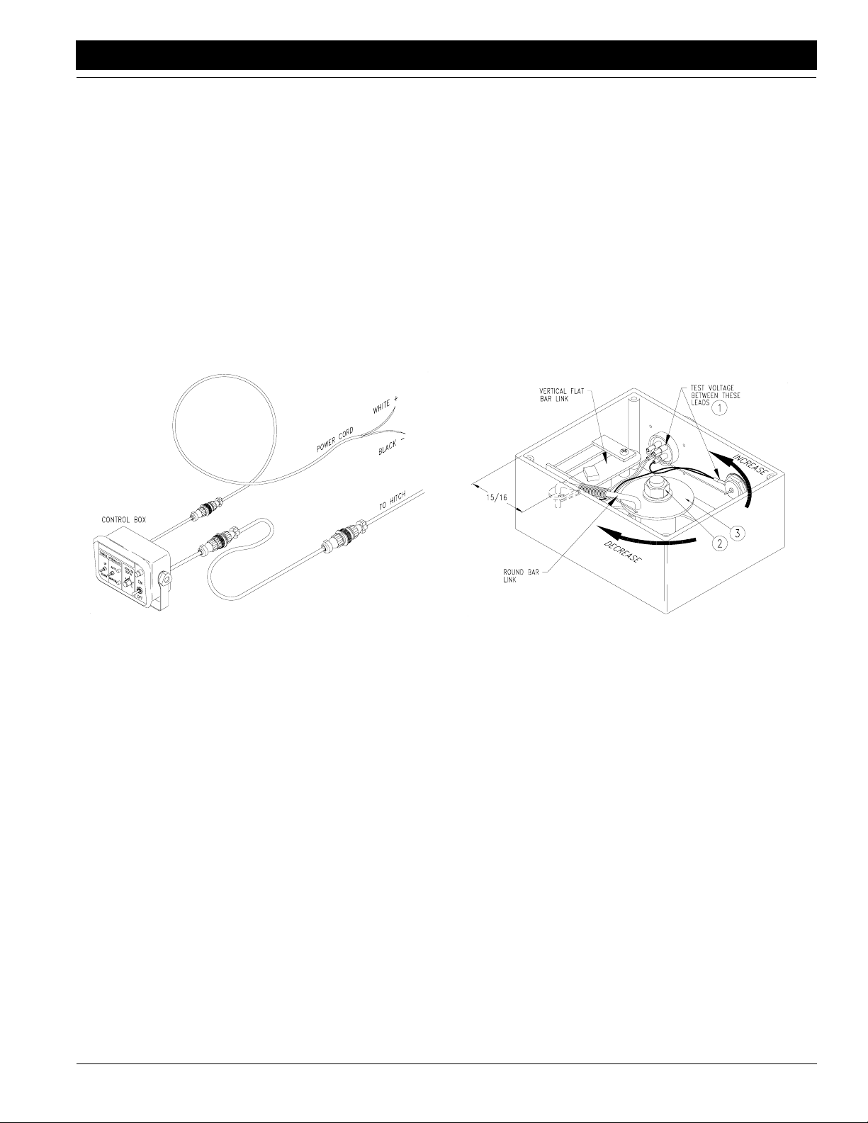
Refer to Figure6
1. Mountthe control boxata convenientlocation inthe
tractor cab. Connect the 12’ extension cable to the
9-pin connector on the back of the control box and
routethecable backtowardthe tractor drawbararea
making sure it will not get kinked or pinched.
2. Connect the power cord to a good uninterrupted 12
voltpower source on the tractor.Connecting directly
to the battery is recommended. Plug the cord into
the lead with the 2-Pin connector on the back of the
control box. The polarity of the power supply is very
important to prevent circuit damage. The white wire
of the power cord must be connected to the "+" positive battery terminal and the black wire to the "-"
negative battery terminal.
With the depth sensing wheel in the max down position, the voltage potential between the lead containing the WHITE WIRE and the ground lead (BLACK
WIRE) in the gauge wheel sensor box (#1) should
be 5 volts DC plus or minus 1/4 volt. To adjust the
gauge wheel sensor box linkage, loosen the 3/8"
hexflange nut (#2) on the sensor spindle and rotate
the circular disk (#3) until the voltage potential betweentheleadcontainingthe WHITE WIRE and the
ground lead (BLACK WIRE) (#1) is 5 volts DC plus
or minus 1/4 volt. Rotating the circular disk counterclockwise increases voltage potential, and rotating
the circular disk clockwise decreases the voltage
potential. Once the correct voltage potential is
achieved,tighten the 3/8" nut. Be careful not to rotate the circular disk as you tighten the nut. Replace
the sensor box cover.
12575
Figure 6
Coulter Command Control Box
Coulter Command
Assembly Adjustments
Refer to Figure7
Coulter command depth sensing wheel assemblies
whicharepre-assembledat the factory are pre-adjusted
and should not require further adjustment. If the sensor
boxat the depth sensing wheel has been field installed,
or if its linkage gets out of adjustment, it must be adjusted using one of the following two procedures:
1. The best and most accurate means of adjusting the
linkage inside the sensor box makes use of a voltmeterwhich reads 0-12 voltsDC.TheControlBoxin
the tractor must be properly connected to a power
source and the POWER switch must be ON. The
TONGUE HYDRAULICS switch should be in the
MANUAL mode. The wiring harness must be connected to the control box and the sensor box. The
depth sensing wheel should be off the ground with
the arm rotated down as far as its spring-loaded
down-pressure link will allow. Remove the cover
from the sensor box and inspect theinternal linkage
for proper assembly.
12619
Figure 7
Sensor Box Adjustments
2. The second means of adjusting the linkage inside
the sensor box involvesmeasuring from the inside
edge of the boxto the left pivot of the formed roundbar link. The depth sensing wheel should be off the
ground and rotated downas far as its spring-loaded
down-pressure link will allow. Remove the cover
from the sensor box and inspect theinternal linkage
for proper assembly.
With the depth sensing wheel in the max down position, the pivot between the vertical flat-bar link and
the formed round-bar link should be 15/16" from the
front inside edge of the sensor box.
With the sensor box linkage properly assembled,
loosen the 3/8" hex flange nut on the sensor spindle
androtatethecirculardiskuntilthepivotbetween the
vertical flat-bar link and the formed round-bar link is
15/16" + or - 1/16" from the front inside edge of the
box. Be careful not to rotate the circular disk as you
retighten the nut. Replace the sensor box cover.
3. Some models of the sensor box have a mark on the
vertical flat-bar link which should line up with a mark
on the link’sslotted mount plate at the correct preset
voltage. With the depth sensing wheel in the max
down position, the marks should line up at a voltage
of5 voltsDC+ or-1/4volt.Aligningthe marks is more
9/21/05
CPH and CP1000 Coulter Command System 148-258M-B
9
Page 12
Section 2 Operating Instructions
Section 2 Operating Instructions
Great Plains Mfg., Inc.
The Coulter Command couples a microprocessor with
electro-hydraulics to provide a state-of-the-art system
formaintaining coulter depth regardless of the terrain or
soil type. It also provides coulter depth adjustment
"FromThe Tractor Cab". A manual feature allows manual control of the front hydraulic tongue cylinder for
hitching, unhitching, or making adjustments. To understand the Coulter Command system, one must be
familiarwith the functions of the hydraulics and the electronic controls.
Load Sensing Hydraulics
To operate Coulter Command, some tractors with loadsensing or constant-flow hydraulics require a bypass
valve,GreatPlains partnumber810-400C.Contact your
Great Plains dealer to order the bypass valve.
NOTE: Failure to install a bypass valve on load-sensingtractorsmaycause major tractor damage. Consult
yourtractor dealertoverifyif the bypass valveis needed.
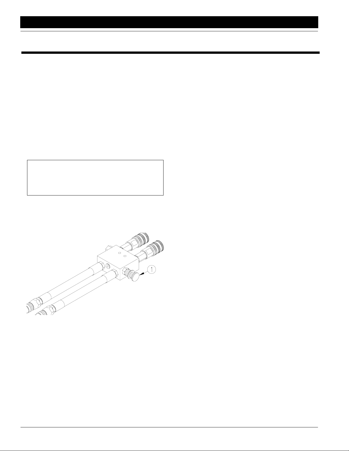
After installing the bypass valve,set valve as follows:
Refer to Figure8
1. Closebypassvalvefor no oilflowbyturning knob (1)
on valveclockwise.
17987
Figure 8
Bypass Valve
2. Adjust flow-control valvefor tractor to a maximum of
10 gpm. If youdo not have a flowmeter, hook a standard8-inch stroke,4-inchbore cylinder tothecircuit.
At 10 gpm, the cylinder will take about 2.6 seconds
to extend.
3. Engage tractor hydraulics for Coulter Command.
4. Using a pressure gauge, turnknob on bypass valve
counterclockwiseuntilpressure gauges reads 1800
psi. Lock bypass valve at this setting.
Hydraulic Hook-Up & Function
Tractors with closed-center hydraulic systems and
variable displacement hydraulic pumps.
(If you are not familiarwith your tractor's hydraulics, consult your tractor dealer.)
For tractors with closed-center hydraulics or pressure/
flow compensated hydraulics which are powered by a
variable displacement hydraulic pump, turn the knurled
control knob on the left side of the hydraulic valve completelyclockwise and lockit in placewiththecircular lock
disk. Do not apply any torque to the control knob after it
bottoms out or valve damage may occur. Be sure the
lock disk is snugged to prevent the control knob from vibrating loose in field operation.
The tongue cylinder hydrauliccircuit consists of the hosesfromports "P" and "T". Once the hydraulicvalveis set
forCLOSED CENTER operation, the Coulter Command
tongue cylinder circuit requires live hydraulic power supplied to the port labeled "P". This is accomplished by
pushing FORWARD on the tractor remote hydraulic lever and LOCKING IT OPEN in this position.
• On John Deere tractors equipped with SOUND-
GUARDRBody you must use the LEVERLOCKCLIP
John Deere Part No. R52667 to lock the lever in the
forward position. See your tractor dealer for purchase
and installation of this clip.
• On John Deere 7000 Series tractors, rotate valve de-
tentselector to MOTOR POSITION to lock the lever in
the forward position.
• On Case-IHMagnumtractorsusethecircuitdesigned
for HYDRAULIC MOTOR CONTROL and lock the leverforwardin the detent position. The detent pressure
will probably have to be turned up to its maximum setting.DONOTtie the hydraulic lever on past the detent
positionwith a strap. This could shift the spool beyond
its designed operating position and cause system
damage. See your tractor dealer for hydraulic system
details.
• On other model tractors use the circuit designed for
HYDRAULIC MOTOR CONTROL and lock the lever
forwardinthe detent position. The detent pressure will
probably have to be turned up to its maximum setting
orsome other mechanicaldetentholder willhavetobe
usedto hold the lever forward.See your tractor dealer
for the proper means of providing constant pressure/
flow to the tongue cylinder circuit.
The Coulter Command hydraulic circuit requires a flow
rate of 8 to 12 gallons per minute forefficient operation.
On high flow rate tractors, the flow control on the tractor
remote mayhaveto be turned down soas not to exceed
12gallons per minute. Flow rates higher than 12 gallons
per minute will not damage the valve, but may cause
poor Coulter Command performance.
The remote tractor hydraulic leverwill have to be locked
in position to supply oil to the "P" port of the hydraulic
control valve, regardless of whether you want to control
the tongue hydraulic cylinder manually or automatically.
CPH and CP1000 Coulter Command System 148-258M-B 9/21/05
10
Page 13

Great Plains Mfg., Inc.
Section 2 Operating Instructions
The CPH transport hydraulic circuit contains the hoses
from the ports marked "V1" and "V2". This circuit must
be connected to one of the remaining circuits for raising
and lowering the transport system. This circuit must receive hydraulic pressure for raising the machine even
while the hydraulictongue circuit is "locked in" for continuoususe. Ifthemachine will notraisewhen the hydraulic
tongue circuit is "locked in," consult your tractor dealer.
You may need to run the transport hydraulic circuit on a
"priority circuit" and the hydraulic tongue circuit on an alternate remote if the tractor hydraulics allows live
hydraulic power to other remotes. If the "priority circuit"
is the only circuit suitable for HYDRAULIC MOTOR
CONTROL, then run the transport hydraulic circuit on
the "priority circuit" and run the hydraulic tongue circuit
onan alternate remote with theCoulter Command valve
inthe OPENCENTERMODE.See "Tractors with open
center hydraulic systems or fixed displacement hydraulic pumps" below.
Tractors with open center hydraulic systems or
fixed displacement hydraulic pumps.
(If you are not familiarwith your tractor's hydraulics, consult your tractor dealer.)
For tractors with open-center hydraulics or on tractors
with fixed displacement hydraulic pumps turn the
knurled control knob on the left side of the hydraulic
valve completely counterclockwise and lock it in place
with the circular lock disk. Be sure the lock disk is
snuggedto preventthecontrolknobfromvibrating loose
in field operation.
The CPH transport hydraulic circuit contains the hoses
from the ports marked "V1" and "V2". This circuit must
be connected to tractor's "priority circuit" to supply hydraulic pressure for raising the machine even while the
hydraulictongue circuit is"lockedin" for continuous use.
The"No.1"hydrauliccircuiton mostopen-centertractors
is the priority circuit.
The tongue cylinder hydrauliccircuit consists of the hosesfrom ports"P"and"T".Connect "P" and"T"to a circuit
other than the "prioritycircuit". Once the hydraulic valve
is set for OPEN CENTER operation, the Coulter Command tongue cylinder circuit requires live hydraulic
power supplied to the port labeled "P". This is accomplished by pushing FORWARDon the tractor remote
hydraulic lever and LOCKING IT OPEN in this position.
The remote tractor hydraulic leverwill have to be locked
in position to supply oil to the "P" port of the hydraulic
control valve, regardless of whether you want to control
the tongue hydraulic cylinder manually or automatically.
The Coulter Command tongue hydraulic circuit requires
a flow rate of 8 to 12 gallons per minute for efficient operation. On high flow rate tractors, turn down the flow
rate on the tractor remote, if possible, so as not to exceed 12 gallons per minute. Flow rates higher than 12
gallons per minute will increase the heat generated by
the Coulter Command circuit when it circulates this high
flow of oil.
Refer to Figure9
WhenoperatingtheCoulterCommandtonguehydraulic
circuit in the OPEN CENTER mode, use poppet style
quick couplers on the hoses connecting to the tractor.
These quick couplers allow better flow through some
tractor remotes and may produce less heat when circulating continuous hydraulic flow through them. Parker
Hannifin offersthe poppet style Pioneer quickcoupler in
their 8010 Series couplers. For tractors with Pioneer
quick couplers use Pioneer 8010-4P poppet style male
couplers when operating in the OPEN CENTER mode.
Poppet Style Ball Style
Figure 9
Quick Couplers
16316
9/21/05
CPH and CP1000 Coulter Command System 148-258M-B
11
Page 14

Section 2 Operating Instructions
Great Plains Mfg., Inc.
Operation of Electronic Controls
1. Connect the power cord to a good uninterrupted 12
voltpower source on the tractor.Connecting directly
to the battery is recommended. Plug the cord into
the lead with the 2-Pin connector on the back of the
control box. The polarity of the power supply is very
important to prevent circuit damage. The white wire
of the power cord must be connected to the "+" positive battery terminal and the black wire to the "-"
negative battery terminal.
2. With the remote tractor hydraulic lever locked in position to supply oil to the "P" port of the hydraulic
control valve, turn the power switch on.
a. Formanual tongue hydrauliccylinder operation,
simply moveUP-DOWN switch. Moving the
switch to the UP position extends the tongue
cylinder, and moving the switch to the DOWN
position retracts the tongue cylinder. If UP retracts the cylinder, then your remote hydraulic
leveris not supplying oil to the "P" portof the hydraulic control valve, or the wires going to the
solenoids A and B are reversed. By moving the
UP-DOWN switch, the AUTO-MANUAL switch
automatically switchesto the MANUALmode.If
you are in the AUTO mode and you want to
manually hold the tongue hydraulic cylinder in
the position set by the automatic controls, just
switch the AUTO-MANUAL switch to MANUAL.
b. For automatic coulter depth control, simply
switchthe AUTO-MANUAL switch to AUTO and
dial in the desired coulter depth you wish to
maintainwith the coulter depth controlknob.
!
Make sure all people, animals, and objects are clear of the
coulter tool bar before switching the tongue hydraulics
switch to the "auto" mode. Sudden automatic lowering of the
coulter tool bar could cause serious personal injury or death.
WARNING!
Turning the coulter depth switch clockwise makes
thecoulters run shallower.Turningthe coulter depth
switch counterclockwise makes the coulters run
deeper.If the hitch is not moving or is on a hard surface,turning thecoulterdepthswitchmaynot cause
thetonguecylinder to retract to the desired position.
The coulters may not penetrate to the desireddepth
until the hitch is moving. The coulter depth setting
can alwaysbe changed "on-the-go" if you desire.
With the AUTO-MANUAL switch in the AUTOmode,
the coulters should maintain a constant depth regardless of terrain, soil type or speed. When lifting
and turning in the field, the tongue cylinder will remainin its last automatically setmid strokeposition.
When the machine is lowered, the coulters will automatically return to their preset depth.
Field Adjustments
Lift Switch
The switch at the transportlift cylinder of the Center PivotHitch determines thepoint in the lift cycle atwhich the
automatic feature of the Coulter Command will be interrupted and the depth sensing gauge wheel will be lifted
offthe ground forturning around. Since theCenter Pivot
Hitch transport tires can be lowered duringoperation to
provideflotation forthedrillinsoftsoil conditions, coulter
command should not beinterrupted and the depth sensing gauge wheel should not be lifted until after the
transport tiresareloweredto the point wheretheyare no
longerused forsystem flotation. This is usually thepoint
inthelift cycle when the drill openers are justbeinglifted
out of the ground.
A 3/8" x 3/8" square ramp attached to a sliding push rod
on the right transport lift cylinder activates a plunger
switchwhich causestheautomaticfeatureof theCoulter
Command to be interrupted and the depth sensing
gauge wheel to be lifted off the ground for turning the
Center Pivot Hitch around in the field.
CPH and CP1000 Coulter Command System 148-258M-B 9/21/05
12
Page 15

Great Plains Mfg., Inc.
Section 2 Operating Instructions
1. To adjust the lift switchtiming, assemble the push rod
tothe cylinder rod clamp using one of thethreeadjustment holes at the bottom of the push rod. When tightening up the 5/16" nylock nut on the pivot bolt, DO
NOT TIGHTEN IT DOWN TIGHT. The bolt and push
rod must be free to move in the slot of the clamp. It is
recommended to assemble the push rod through its
lower-most hole. BE CAREFUL NOT TO "BOTTOM
OUT" THE LIFT SWITCHPLUNGER when the plunger roller climbs the surface of the 3/8" square ramp.
2. To adjust the lift switch position, loosen the two #10
screws and slide it forward or backward in the slotted
switch mount holes so the plunger moves "in" only
about 1/8" when the cam activates it. DO NOT "BOTTOM OUT" THE LIFT SWITCH PLUNGER.
!
Shut the tractor off and put all hydraulic valve levers in neutral
position before attempting to work on or crawl under the machine. Do not crawl under a raised machine without the transport lock pins securely in place. Sudden hydraulic activation or
failure could cause serious injury or death.
Aproperly adjusted lift switchallows the automatic coulter
depth feature to be interrupted early in the lift cycle. This
providedthefastestlift cycle timeswhenturning around in
thefield. Operatingthe lift switchearly in the lift cycle, also
provides the maximum amount of time for the depth sensing gauge wheel cylinder to completely extend as the
machine is lowered back to field position. It is important
thatthe depth sensing gauge wheel cylinder always be fully extendedwhen the Center Pivot Hitch isin field position
toallowthedepth sensing gauge wheel to float through its
full range of motion.
Speed Sensor
The Coulter Command depth control system automatically compensates for changes in ground speed. A speed
sensor and speed sensor plate mounted behind the
coulter depth sensing wheel monitors the ground speed
so the Coulter Command can adjust for it. This sensor
should be in close proximity to the speed sensor plate. In
general, it should never need adjustment. If the sensor
WARNING!
does get moved, it should be adjusted against the speed
sensor plate until is just touches the plate in the closest
part of the rotation. A bent speed sensor plate should be
straightenedorreplaced immediately. Toadjust the speed
sensor,loosen the two #6 screws on the sensor and slide
ittowardthe speed sensorplate.Rotate the depth sensing
wheelto the position where the speedsensorplate is closest to the sensor mount, and retighten the sensor mount
screws where the sensor just touches the speed sensor
plate.
Hydraulic Valve
All adjustable valve cartridges on the hydraulic valve
blocks are preset at the manufacturer and should not be
tampered with. Tamperingwith a cartridge valve could result in decreased lift cycle times forthe Center Pivot Hitch.
The only required adjustment is on the upper hydraulic
control valve.This valve contains a rotaryknob for setting
the Coulter Command to be used with either OPEN CENTERED or CLOSED CENTERED tractor hydraulics.
Check the owners manual of your tractor to determine
what type of hydraulic system you have.
Referto “Hydraulic Hook-Up & Function” on page 10 of
this manual for setting the hydraulic control valve for your
style of tractor.
Transport Cylinder Depth Channels
Whenplanting in soft soil conditions wheresinking of your
drillgaugewheelsmaybe a problem, a cylinder stop channel package (GP# 148-181A) is available to allow your
transport tires to run on the ground and assist in the supporting the drill and hitch weight. The 148-181A cylinder
stopchannel packagecontainstwo cylinder stopchannels
(one for each transport cylinder). Since the transport hydraulics is a master-slave system, it is only necessary to
useone cylinder stopchannelon the masterliftcylinderon
the left side of the Center Pivot Hitch. The other cylinder
stop channel will not workon the slavecylinder located on
theright side of the Center PivotHitch because the lift control switch for the Coulter Command mounts to that
cylinder.Useonlyonecylinder stop channel onthemaster
lift cylinder (left side) on Center Pivot Hitches equipped
with Coulter Command.
9/21/05
CPH and CP1000 Coulter Command System 148-258M-B
13
Page 16

Section 3 Troubleshooting
Section 3 Troubleshooting
Problem Possible Cause Solution
Great Plains Mfg., Inc.
Coulters move up when the
down switch is operated and
down when the up switch is
operated.
Automatic coulter depth control stops adjusting coulter
depth.
T urningthe coulter depth knob
does not set coulters deep
enough.
Not supplying oil to the "P" port of the
hydraulic valve.
Solenoids wired backward or hoses from
port "A" and port "B" reversed at the
hydraulic valve.
tongue hydraulics switch bumped to
"manual" mode.
Tractor remote hydraulic lever not locked
for constant oil supply to valve.
System variables out of adjustment Turn power switch OFF and back on again
If the tongue cylinder runs completely
retracted, the tractor drawbar is to high.
In extremely hard conditions with the
machine standing the tongue cylinder
pulses but does not retract.
If the coulter depth knob is turned to "A"
and the tongue cylinder will not completely retract when moving through the
field then the internal sensor box linkage is
not set correctly.
Reverse the remote hydraulic lever in the
tractor.
Reverse the hoses at the quick couplers.
Unplug solenoids and swap wire leads to
them.
Flip tongue hydraulics switch back to
"auto" mode.
Lock Tractor remote hydraulic lever with
rubber tarp strap or other means.
so the system variables can reset. Then
flip AUTO-MANUAL switch to AUTO.
Use a straight drawbar or one which
sweeps down.
This is perfectly normal.The cylinder will
not penetrate the coulters on a stationary
machine in hard conditions.Pull forward
and check coulter depth on a moving
machine.
Adjust the sensor box internal linkage. See
"Coulter Command Assembly Adjust-
ments" on page 9.
The hydraulic valve constantly
pulses when you are stopped
to refill or adjust something.
T urningthe coulter depth knob
to "E" does not allow the
coulters to run shallow
enough.
Depth sensing gauge wheel
not lifting off the ground when
Center Pivot Hitch is raised.
If the sensor box linkage is properly
adjusted and tongue cylinder constantly
pulses while moving through the field but
the front tongue cylinder will not retract,
you do not have enough system weight.
Hard soil conditions are hindering coulter
penetration while stopped.
The internal sensor box linkage is not set
correctly.
Coulter Command power is OFF or 12 volt
power has been interrupted.
The lift switchhas become disconnected or
the lift switch cam on the right transport lift
cylinder has been damaged.
Add weights to the pull hitch frame weight
brackets. Add tool bar weight brackets to
coulter tool bars.
Flip tongue hydraulicsswitch to "manual"
mode while you are stopped or turncoulter
command power "off". Pulsing does not
hurt the valve, but can be annoying.
Adjust the sensor box internal linkage. See
"Coulter Command Assembly Adjust-
ments" on page 9.
Coulter Command must be connected and
the power must be ON for the depth sensing gauge wheel to raise when the All
Seeds Hitch is raised. The depth sensing
gauge wheel should raise with the transport lift circuit with Coulter Command in
either the AUTO or MANUAL mode is long
as the power is ON.
Inspect and adjust the lift switch and push
rod cam. See "Lift Switch" under Section
2 "Operating Instructions" on page 12.
Check cable connections on lift switch
lead.
CPH and CP1000 Coulter Command System 148-258M-B 9/21/05
14
Page 17

Great Plains Mfg., Inc.
Section 3 Troubleshooting
Problem Possible Cause Solution
Depth sensing gauge wheel
not lowering to the ground
when Center Pivot Hitch is lowered, or depth sensing gauge
wheel cylinder not fully extending when the machine is lowered.
Coulterdeptherraticorwillnot
adjust when you turn the
"DEPTH CONTROL" dial.
The lift switchhas become disconnected or
the lift switch cam on the right transport lift
cylinder has been damaged.
Relief valve "M3" is set too low. Turn valve adjustment screw on top of
Moisture present in the master control
box.
Hydraulic flow rates of more than 12
gallons per minute to the hydraulic control valvewhen operating in the
CLOSED-CENTER mode.
Inspect and adjust the lift switch and push
rod cam. See "Lift Switch" under Section
2 "Operating Instructions" on page 12.
Check cable connection on lift switch lead.
valve"M3" one eighth turn clockwise.Valve
"M3" is preset to relieve at 600 psi. Turning
the adjustment screw one eighth turn
clockwise increases the relief setting by
approximately 75 psi.
!
Any attempt to set valve "M3" above 1200
psi could result in system malfunction. Setting the valve "M3" above 750 psiwill slow
down the lift cycle time.
The master control box in the tractor
mustbe keptdry.Moisture on thecircuit
board or in the control terminals will
cause false readings.
Turn down the flow rate on the tractor
remote which is providing oil to the
tongue hydrauliccircuit.
CAUTION!
System generating excess
heat when operating in the
OPEN CENTER MODE.
Inconsistent 12-volt power supply.
The OPEN CENTER - CLOSED CENTER control knob is not turned
completely counterclockwise.
Ball style quick couplers may produce
more heat when circulating continuous
hydraulic flow through them.
Connect the power cord directly to the
battery. The Coulter Command electrical circuit must have a good uninterrupted power supply. Fluctuations in
the power supply will cause inconsistent electrical readings.
Turn theknurledcontrolknob on the left
side of the hydraulic valvecompletely
counterclockwise and lock it in place
with the circular lock disk.
Use poppet style male quick couplers.
Fortractorswith Pioneerquickcouplers
usePioneer8010-4Ppoppet stylemale
couplers when operating in the OPEN
CENTER mode. See Figure 8, page
10.
9/21/05
CPH and CP1000 Coulter Command System 148-258M-B
15
Page 18

Section 3 Troubleshooting
Problem Possible Cause Solution
Great Plains Mfg., Inc.
T ransport lift cylinders will not
lift the Center Pivot Hitch for
transport.
OPEN-CENTER tractors with multiple
sets of hydraulic outlets use the #1 circuit for priority flow which slows down
orcutsoffflow to the other circuits. This
problemwill occur if Coulter Command
ports "P" and "T" are plugged into the
#1 circuit.
On CLOSED-CENTER tractors the
Coulter Command should be connected to a circuit capable of HYDRAULIC
MOTOR CONTROL for supplying constantpressure/flowtoremote locations.
If the machine will not raise when the
hydraulic tongue circuit is "locked in,"
consult your tractor dealer. You may
need to run the transport hydraulic circuit on a "priority circuit" and the
hydraulictongue circuit on an alternate
remote if the tractor hydraulics allows
live hydraulic power to other remotes.
Connect transport lift circuit ports "V1" and
"V2" to the #1 hydraulic circuit on OPENCENTER tractors. Ports "P" and "T" of the
Coulter Command hydraulics should connect to another circuit other than the #1 circuit on OPEN-CENTER tractors.
On CLOSED-CENTER tractors, if the
"priority circuit" is the only circuit suitable for HYDRAULIC MOTOR
CONTROL or supplying constant pressure/flow to remote locations, then run
the transport hydraulic circuit on the
"priority circuit" and run the hydraulic
tongue circuit on an alternate remote
with the Coulter Command valvein the
OPENCENTER MODE.See "Tractors
with open center hydraulic systems
or fixed displacement hydraulic
pumps," page 11.
CPH and CP1000 Coulter Command System 148-258M-B 9/21/05
16
Page 19

Great Plains Mfg., Inc.
Section 3 Troubleshooting
System Schematics
If problems occur in the hydraulic or electric systems,
refer to the schematics below and on page 18 to help
locate the problem.
Hydraulic Schematic
16313
9/21/05
CPH and CP1000 Coulter Command System 148-258M-B
17
Page 20

Section 3 Troubleshooting
Electrical Schematic
Great Plains Mfg., Inc.
16314
CPH and CP1000 Coulter Command System 148-258M-B 9/21/05
18
Page 21

Great Plains Mfg., Inc.
Section 4 Maintenance and Lubrication
Section 4 Maintenance and Lubrication
Maintenance
The Coulter Command is relatively maintenance free.
The switches,sensors, and linkages should not need
any routine adjustment unless they are moved or
damaged.
Lubrication
Lubrication Symbols
50
As
Required
Lubrication is required every 50 hours of operation.
10
12620
Use a multipurpose spray lube. Use as required.
Do not over lubricate.
Seasonally
Lubrication is requiredLubrication is required every 10 hours of operation.
2 - 3 Years
Axle Bearings
Repack
Type of Lubrication: Wheel Bearing Grease
9/21/05
CPH and CP1000 Coulter Command System 148-258M-B
19
Page 22

Section 5 Parts
Section 5 Parts
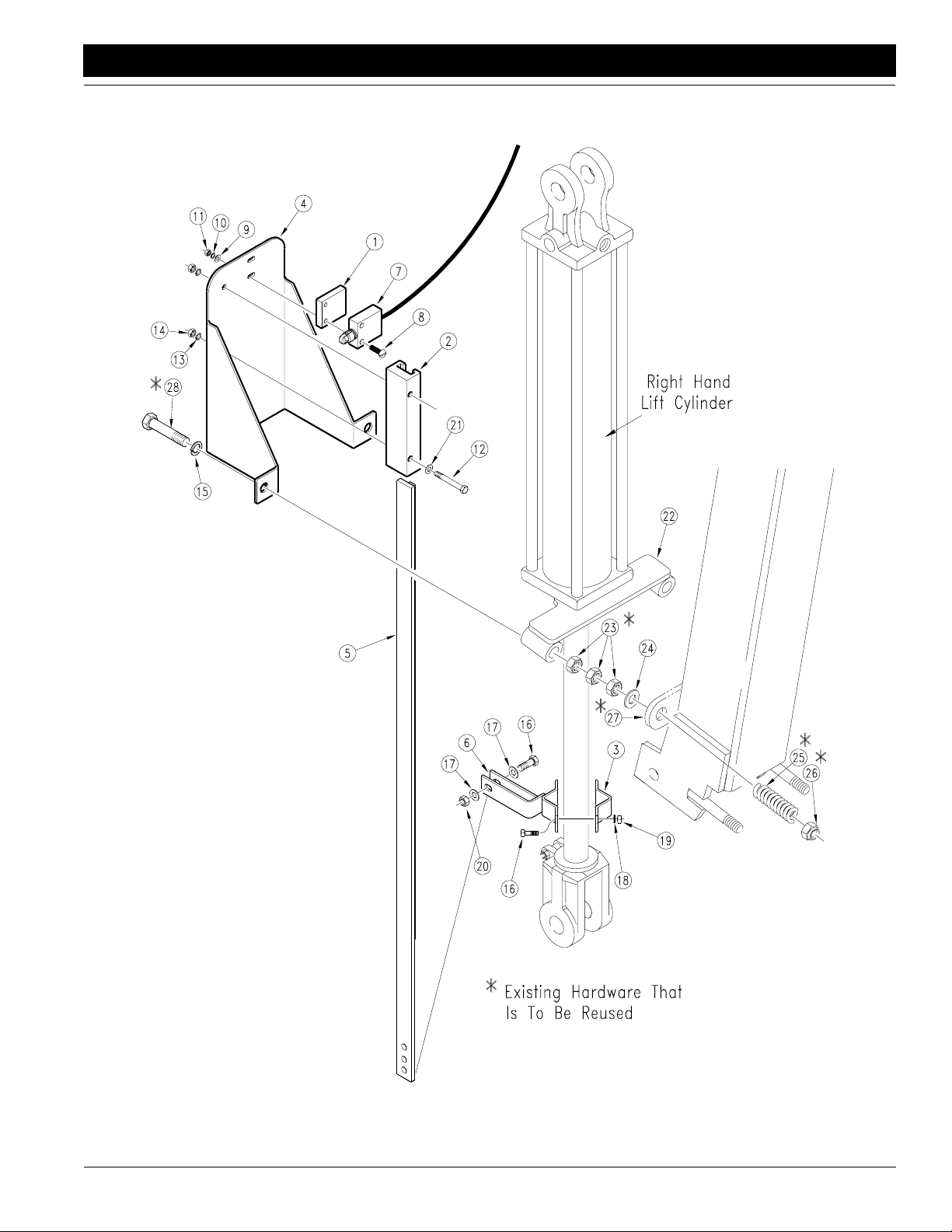
Coulter Depth Control Hydraulics
Great Plains Mfg., Inc.
CPH and CP1000 Coulter Command System 148-258M-B 9/21/05
20
16317
Page 23

Section 5 Parts
Ref. Part No. Part Description
1. 802-279C Bolt, Hex Head 5/16"-18 x 4"
2. 810-214C Valve, Electronic Depth Control
3. 811-063C Fitting, Hydraulic Elbow 3/4" JIC Male x 3/4" O-Ring Male
4. 811-383C Hose, Hydraulic 1/2" R1 x 122" Long x 1/2" NPT Male x 3/4" JIC Female
5. 803-020C Nut, Hex 1/2"-13
6. 804-015C Washer, Lock Spring 1/2"
7. 811-088C Fitting, Hydraulic Adaptor 3/4" O-Ring Male x 3/4" JIC Male
8. 811-331C Hose, Hydraulic 1/2" R2 x 020 3/4" JIC Female
9. 811-172C Orifice Plate /16" x 3/4"
10. 803-008C Nut, Hex 5/16"-18
11. 804-009C Washer, Lock Spring 5/16"
12. 802-046C Bolt, Hex Head 1/2"-13 x 5 1/2" Long
13. 148-415D Hydraulic Valve Mount
14. 811-340C Hose, Hydraulic 1/2" R2 x 030 3/4" JIC Female
15. 805-004C Pin Clevis 1" x 2 3/4" Usable Long
16. 805-010C Pin Hair Cotter.094
17. 148-283H Cylinder Pin
18. 804-029C Washer, Flat 1" SAE
19. 805-021C Pin, Cotter 1/4" x 2" Long
20. 811-280C Hydraulic Fitting, Elbow 1/2" NPT Female x 3/4" O-Ring Male
21. 811-065C Hydraulic Fitting, Elbow 9/16" JIC Male x 9/16" O-Ring Male
22. 811-443C Hydraulic Hose 1/4" R2 x 036 9/16" JIC Female
23. 810-259C Cylinder 1.50" x 4.0" x 0.75" Weld 1" Pin
24. 802-333C Bolt, Hex Head 5/16"-18 x 3 1/2" Long
25. 810-262C Lift Circuit Manifold
9/21/05 Great Plains Mfg., Inc. CPH and CP1000 Coulter Command System 148-258M-B
-21
Page 24

Section 5 Parts
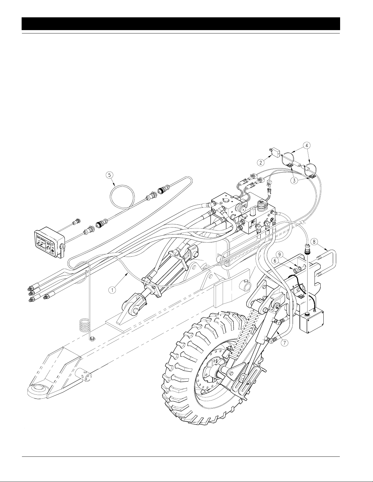
Coulter Command Electronics
12623
22
CPH and CP1000 Coulter Command System 148-258M-B 9/21/05
Great Plains Mfg., Inc.
Page 25

Section 5 Parts
Ref. Part No. Part Description
1. 823-103C Control Box
2. 823-110C Power Cord
3. 823-108C Control Box Cable
4. 823-104C Wire Harness
9/21/05 Great Plains Mfg., Inc. CPH and CP1000 Coulter Command System 148-258M-B
-23
Page 26

Section 5 Parts
Coulter Command Gauge Wheel Assembly
12594
24
CPH and CP1000 Coulter Command System 148-258M-B 9/21/05
Great Plains Mfg., Inc.
Page 27

Section 5 Parts
Ref. Part No. Part Description
1. 823-105C Gauge Wheel Sensor Box
2. 803-068C Nut, Hex Flange 3/8"-16
3. 804-012C Washer, Flat 3/8" SAE
4. 803-008C Nut, Hex 5/16"-18
5. 804-009C Washer, Lock Spring 5/16"
6. 148-507D Gauge Wheel Sensor Mount
7. 804-004C Washer Internal Star #10
8. 801-051C Screw, Cross Recess Pan Head Machine #10-24 x 7/16" Long
9. 802-091C Bolt, Hex Head 1/2"-13 x 1 1/2" Long
10. 800-148C Cable Tie Mount
11. 800-149C Cable Tie 6" Long Releasable
12. 822-041C Flangette 47 MST
13. 822-040C Bearing 3/4"bore 47mm Sphere OD
14. 802-092C Bolt, Round Head Square Neck 5/16"-18 x 3/4" Long
15. 148-382D Coulter Command Gauge Wheel Mount Pin
16. 806-105C U-Bolt 5/8"-11 x 4 1/32" x 6 Long
17. 804-022C Washer, Lock Spring 5/8"
18. 803-021C Nut, Hex 5/8"-11
19. 148-199H CPH Gauge Wheel Mount
20. 804-015C Washer, Lock Spring 1/2"
21. 803-020C Nut, Hex 1/2"-13
22. 802-128C Bolt, Hex Head 1/2"-13 x 2 Long
23. 148-381D CPH Gauge Wheel Mount Ear
24. 148-197H Gauge Wheel Spring
25. 817-129C Flng Bushing 1 1/8" x 1 3/4"
26. 805-146C Pin, Roll 1/4" x 2 Long
27. 817-084C Parallel Arm Pivot Bushing
28. 148-413D Gauge Wheel Spring Spacer Tube
29. 822-091C Bearing Cone 15123
30. 816-098C Seal, 1 3/8" ID x 2.441 OD X.313
31. 802-041C Bolt, Hex Head 1/2"-13 x 3 1/2" Long
32. 804-109C Washer, Flat #6
33. 804-050C Washer, Lock #6 SS
34. 801-017C Screw, Pan Head 6-32 x 1/2" SS
35. 823-106C Speed Sensor
36. 148-177H Gauge Wheel Arm
37. 802-104C Bolt, Lug 1/2"-20 x 1" Long
38. 816-035C Valve Stem
39. 814-115C Tire, 5.00-15SL 4-Ply
40. 814-116C Wheel, 15" Dia X 4 1/2" Wide x 4-Bolt
41. 148-246S 5.00-15 SL 4-Ply Wheel & Tire Assembly
42. 148-426D Speed Sensor Plate
43. 200-001D Hub Grease Cap
44. 805-016C Pin, Cotter 3/16" x 1 x 1/4"
45. 803-029C Nut, Hex Slotted 7/8"-14
46. 804-055C Washer, Spindle - 7/8"
47. 312-151S 120 Pull Hub & Cups Assembly
48. 822-092C Bearing Cup 15245
49. 312-106D 4-Bolt Hub
50. 800-001C Grease Zerk Straight 1/4"-28
51.
52. 04003013 Clevis Pin
53. 805-067C Pin, Cotter 1/8" x 3/4"
54. 810-259C Cylinder 1.50" x 4.0" x 0.75" Weld 1" Pin
55. 804-017C Washer, Flat 1/2" USS
56. 805-128C Pin Clevis 1/2" x 2 3/4"
816-193C Gauge Wheel Sensor Box Gasket
9/21/05 Great Plains Mfg., Inc. CPH and CP1000 Coulter Command System 148-258M-B
-25
Page 28

Section 5 Parts
Top Link Assembly (Jan. 1, 2001)
12601
26
CPH and CP1000 Coulter Command System 148-258M-B 9/21/05
Great Plains Mfg., Inc.
Page 29

Section 5 Parts
Ref. Part No. Part Description
1. 148-217V 94 All Seeds Top Link Tube Assembly (Includes 1 Each Of Items #2 Through 7)
2. 148-085H Level Link Adjuster
3. 803-034C Nut, Hex 1 1/4"-7
4. 148-198H Top Link
5. 802-059C Bolt, Hex Head 5/8"-11 x 3" Long
6. 803-024C Nut, Lock 5/8"-11
7. 148-084H Level Link Lock Plate
8. 807-063C Spring, Level Link Lock
9. 802-073C Bolt, Hex Head 1"-8 x 4" Long
10. 804-027C Washer, Lock Spring 1"
11. 803-031C Nut, Hex 1"-8
9/21/05 Great Plains Mfg., Inc. CPH and CP1000 Coulter Command System 148-258M-B
-27
Page 30

Section 5 Parts
Coulter Command Switch Mount
12603
28
CPH and CP1000 Coulter Command System 148-258M-B 9/21/05
Great Plains Mfg., Inc.
Page 31

Section 5 Parts
Ref. Part No. Part Description
1. 148-500D Switch Spacer
2. 817-170C Switch Guide Block
3. 148-510D Cylinder Rod Clamp
4. 148-502D Switch Mount
5. 148-247H Push Rod
6. 148-264H Cylinder Rod Clamp
7. 823-107C Lift Switch
8. 801-085C Screw, Round Head #10-24 x 1 1/2" Long
9. 804-046C Washer, Flat #10
10. 804-054C Washer, Lock #10
11. 803-001C Nut, Hex #10-24
12. 802-152C Bolt, Hex Head 1/4"-20 x 2" Long
13. 804-006C Washer, Lock Spring 1/4"
14. 803-006C Nut, Hex 1/4"-20
15. 804-015C Washer, Lock Spring 1/2"
16. 802-010C Bolt, Hex Head 5/16"-18 x 1 1/4" Long
17. 804-010C Washer, Flat 5/16" USS
18. 804-009C Washer, Lock Spring 5/16"
19. 803-008C Nut, Hex 5/16"-18
20. 803-084C Nut, Hex Nylock 5/16"-18
21. 804-007C Washer, Flat 1/4" SAE
9/21/05 Great Plains Mfg., Inc. CPH and CP1000 Coulter Command System 148-258M-B
-29
Page 32

Section 5 Parts
Lift Circuit Manifold (810-262C)
13479
30
CPH and CP1000 Coulter Command System 148-258M-B 9/21/05
Great Plains Mfg., Inc.
Page 33

Section 5 Parts
Ref. Part No. Part Description
1. 34702171 Orifice Disk.031
2. 39680008 Coil, 12VDC
3. 86020224 NC Bi-Directional
4. 61000000 1/16" NPTF Plug
5. 30102663 Manifold
6. 34952061 Piston Assembly
7. 86020028 Check Valve
8. 87410001 Super Check
9. 62010018 Manifold Tag
10. 33702007 Cavity Plug
11. 85002929 P.O. Relief
12. 10000001 Hydraulic Fitting #4 SAE Male x #6 SAE Female (Only on some models)
13. Seal Kit For Cartridge Valves (Refer To The Illustrations Below
For Proper Seal Kit Identification.)
NOTE: Each o-ring kit contains all of the o-rings for the series of valve on
which it is used. Not all of the seals will be used on every valve.
Each kit also contains a packet of sealant which is to be used on the threads
of the valve when it is re-installed into the manifold.
Seal Kits For Cartridges in Lift Circuit Manifold 810-262C
Refer to Page 34 For Full Scale O-Ring/Back-up Ring Identification Chart
Relief Valve
Use Seal Kit 810-228C
(Ref. Item #11)
13634
"A" size
o-ring
"B" size
thick
back-up
"B" size
o-ring
NC Bi-Dir
Use Seal Kit 810-271C
(Ref. Item #3)
"B" size
o-ring
13637
"A" size
"A" size
o-ring
"B" size
thin
back-up
Super Check
Use Seal Kit 810-235C
(Ref. Item #8)
o-ring
"B" size
o-ring
"B" size
thick
back-up
12589
Piston Assy.
Use Seal Kit 810-271C
(Ref. Item #6)
"B" size
thin back-up
13636
"B" size
o-ring
Check Valve
Use Seal Kit 810-272C
(Ref. Item #7)
"A" size
o-ring
"B" size
o-ring
12589
"B" size
thick
back-up
Cavity Plug
Use Seal Kit 810-228C
(Ref. Item #10)
"A" size
o-ring
"B" size
thin
back-up
"B" size
o-ring
13635
"B" size
thin
back-up
9/21/05 Great Plains Mfg., Inc. CPH and CP1000 Coulter Command System 148-258M-B
-31
Page 34

Section 5 Parts
Coulter Depth Control Valve (810-214C)
12292
32
CPH and CP1000 Coulter Command System 148-258M-B 9/21/05
Great Plains Mfg., Inc.
Page 35

Section 5 Parts
Ref. Part No. Part Description
1. 39680008 Delta Coil 12VDC With Connector
2. 85002279 Delta 3W2P Valve
3. 810-265C Delta Shuttle Valve
4. 61000000 Delta 1/16" NPT Plug
5. 85002006 Delta Check Valve
6. 34952104 Delta Piston Assembly
7. 87410043 Delta PCR Valve
8. 30102610 Delta Coulter Command Manifold
9. 62010056 Delta PCR Sticker
10. 62010053 Delta Notice Tag
11. Seal Kit For Cartridge Valves (Refer To The Illustrations Below
For Proper Seal Kit Identification.)
NOTE: Each o-ring kit contains all of the o-rings for the series of valve on
which it is used. Not all of the seals will be used on every valve.
Each kit also contains a packet of sealant which is to be used on the threads
of the valve when it is re-installed into the manifold.
3W2P Valve
Use Seal Kit 810-228C
(Ref. Item #2)
"C" size
o-ring
"B" size
o-ring
12587 12590
Seal Kits For Coulter Depth Control Valves
Refer to Page 34 For Full Scale O-Ring/Back-up Ring Identification Chart
Shuttle Valve
Use Seal Kit 810-228C
(Ref. Item #3)
"B" size
o-ring
12588
"A" size
o-ring
"C" size
thin
"B" size
thin
back-up
"A" size
o-ring
"C" size
thick
back-up
"C" size
o-ring
"B" size
thick
back-up
Piston Valve
Use Seal Kit 810-228C
"B" size
thick back-up
Check Valve
Use Seal Kit 810-228C
(Ref. Item #5)
12589
(Ref. Item #6)
"B" size
o-ring
PCR Valve
Use Seal Kit 810-235C
(Ref. Item #7)
"A" size
o-ring
"B" size
o-ring
"B" size
thick
back-up
"C" size
o-ring
"E" size
o-ring
12591
"A" size
o-ring
"C" size
back-up
"E" size
back-up
9/21/05 Great Plains Mfg., Inc. CPH and CP1000 Coulter Command System 148-258M-B
-33
Page 36

Section 5 Parts
O-Ring Identification Chart
(Match o-rings and back-up rings to full size illustrations below for identification.)
810-228C For
7/8"-14 Series Valves
A
OD .949
ID .754
B
OD .629
ID .489
C
OD .691
ID .551
810-235C For
1 5/16"-12 Series Valves
A
OD 1.403
ID 1.170
B
OD 1.129
ID .989
C
OD 1.126
ID .924
810-271C For
3/4"-16 Series Valves
A
OD .818
ID .644
B
OD .504
ID .364
C
OD .566
ID .426
D
OD .629
ID .489
D
OD .754
ID .614
Scale: 1=1
D
OD 1.068
ID .862
E
OD 1.002
ID .798
810-272C For
5/8"-18 Check Valves
OD .694
ID .530
OD .504
ID .364
F
OD 1.193
ID .987
34
CPH and CP1000 Coulter Command System 148-258M-B 9/21/05
Great Plains Mfg., Inc.
A
B
Page 37

Section 5 Parts
Kit No. Description
810-228C For 7/8"-12 Series Valves
Includes: 2 Each Of The Thin Back-Up Rings, Sizes B, C, And D
1 Each of The Thick Back-Up Rings, Sizes C and D.
2 Thick "B" Size Back-Up Rings
1 Each Of O-Rings Sizes A, B, C, And D
810-235C For 1 5/16"-12 Series Valves
Includes: 1 Each of Sizes A, B, C, D, E, And F
2 Each of Back-Up Rings Sizes B, C, D, E, And F
810-271C For 3/4"-16 Series Valves
Includes: 2 Each Of The Thin Back-Up Rings, Sizes B, C, And D
1 Each of The Thick Back-Up Rings, Sizes B.
1 Each Of O-Rings Sizes A, B, C, And D
810-272C For 5/8"-18 Check Valves
Includes:
1 Each of The Thick Back-Up Rings, Sizes B.
1 Each Of O-Rings Sizes A, And B.
9/21/05 Great Plains Mfg., Inc. CPH and CP1000 Coulter Command System 148-258M-B
-35
Page 38

Appendix
Appendix
Torque Values Chart for Common Bolt Sizes
Great Plains Mfg., Inc.
Bolt Head Identification
Bolt Size
(Inches)
1
in-tpi
1/4" - 20 7.4 5.6 11 8 16 12 M 5 X 0.8 436597
1/4" - 28 8.5 6 13 10 18 14 M 6 X 1 7 5 11 8 15 11
5/16 - 18 15 11 24 17 33 25 M 8 X 1.25 17 12 26 19 36 27
5/16" - 24 17 13 26 19 37 27 M 8 X 1 18 13 28 21 39 29
3/8" - 16 27 20 42 31 59 44 M10 X 1.5 33 24 52 39 72 53
3/8" - 24 31 22 47 35 67 49 M10 X 0.75 39 29 61 45 85 62
7/16" - 14 43 32 67 49 95 70 M12 X 1.75 58 42 91 67 125 93
7/16" - 20 49 36 75 55 105 78 M12 X 1.5 60 44 95 70 130 97
1/2" - 13 66 49 105 76 145 105 M12 X 1 90 66 105 77 145 105
1/2" - 20 75 55 115 85 165 120 M14 X 2 92 68 145 105 200 150
9/16" - 12 95 70 150 110 210 155 M14 X 1.5 99 73 155 115 215 160
9/16" - 18 105 79 165 120 235 170 M16 X 2 145 105 225 165 315 230
5/8" - 11 130 97 205 150 285 210 M16 X 1.5 155 115 240 180 335 245
5/8" - 18 150 110 230 170 325 240 M18 X 2.5 195 145 310 230 405 300
3/4" - 10 235 170 360 265 510 375 M18 X 1.5 220 165 350 260 485 355
3/4" - 16 260 190 405 295 570 420 M20 X 2.5 280 205 440 325 610 450
7/8" - 9 225 165 585 430 820 605 M20 X 1.5 310 230 650 480 900 665
7/8" - 14 250 185 640 475 905 670 M24 X 3 480 355 760 560 1050 780
1" - 8 340 250 875 645 1230 910 M24 X 2 525 390 830 610 1150 845
1" - 12 370 275 955 705 1350 995 M30 X 3.5 960 705 1510 1120 2100 1550
1-1/8" - 7 480 355 1080 795 1750 1290 M30 X 2 1060 785 1680 1240 2320 1710
1 1/8" - 12 540 395 1210 890 1960 1440 M36 X 3.5 1730 1270 2650 1950 3660 2700
1 1/4" - 7 680 500 1520 1120 2460 1820 M36 X 2 1880 1380 2960 2190 4100 3220
1 1/4" - 12 750 555 1680 1240 2730 2010
1 3/8" - 6 890 655 1990 1470 3230 2380
1 3/8" - 12 1010 745 2270 1670 3680 2710
1 1/2" - 6 1180 870 2640 1950 4290 3160
1 1/2" - 12 1330 980 2970 2190 4820 3560
Torque tolerance + 0%, -15% of torquing values. Unless otherwise specified use torque values listed above.
Grade 2 Grade 5
N · m2ft-lb3N · m ft-lb N · m ft-lb mm x pitch
Grade 8
Bolt Size
(Metric)
4
N · m ft-lb N · m ft-lb N · m ft-lb
1
in-tpi = nominal thread dia.in inches-threads per inch
2
N· m = newton-meters
3
ft-lb= foot pounds
4
mm x pitch = nominal thread dia. in millimeters x thread pitch
Bolt Head Identification
5.8 8.8 10.9
Class 5.8 Class 8.8 Class 10.9
Tire Inflation Chart
Tire Size Inflation PSI Tire Size Inflation PSI
7.50 x 20" 4-Ply Drill Rib 28 11L x 15" 6-Ply Rib Implement 28
9.0 x 22.5 10-Ply Highway Service 70 70 11L x 15" 12-Ply Rib Implement 52
9.0 x 24" 8-Ply Rib Implement 40 12.5L x 15" 8-Ply Rib Implement 36
9.5L x 15" 6-Ply Rib Implement 32 12.5L x 15" 10-Ply Rib Implement 44
9.5L x 15" 8-Ply Rib Implement 44 16.5L x 16.1" 10-Ply Rib Implement 36
9.5L x 15" 12-Ply Rib Implement 60 41 x 15" x 18 - 22-Ply Rib Implement 44
CPH and CP1000 Coulter Command System 148-258M-B 9/21/05
36
Page 39

Great Plains Mfg., Inc.
Appendix
Warranty
Great Plains Manufacturing, Incorporated warrants to the original purchaser that this seeding equipment will be free from defects in material
and workmanship for a period of one year from the date of original purchasewhen used as intended and undernormal service and conditions
for personal use; 90 days for commercial or rental purposes. This Warranty is limited to the replacement of any defective part by Great Plains
Manufacturing, Incorporated and the installation by the dealer of any
such replacement part. Great Plains reserves the right to inspect any
equipment or part which are claimed to have been defective in material
or workmanship.
This Warranty does not apply to any part or product which in Great
Plains’ judgement shall have been misused or damaged by accident or
lack of normal maintenance or care, or which has been repaired or altered in a way which adversely affects its performance or reliability, or
which has been used for a purpose for which the product is not designed. This Warranty shall not apply ifthe product is towed at a speed
in excess of 20 miles per hour.
Claims under this Warranty must bemade to the dealer whichoriginally
sold the product and all warranty adjustments must by made through
such dealer. Great Plains reserves the right to make changes in materials or design of the product at any time without notice.
This Warranty shall not be interpreted to render Great Plains liable for
damages of any kind, direct, consequential, or contingent, to property.
Furthermore,GreatPlainsshallnot be liable for damages resulting from
any cause beyond its reasonable control. This Warranty does not extend to loss of crops, losses caused by harvest delays or any expense
or loss for labor, supplies, rental machinery or for any other reason.
No other warranty of any kind whatsoever, expressed or implied,
is made with respect to this sale; and all implied warranties of
merchantability and fitness for a particular purpose which exceed the obligations set forth in this written warranty are hereby
disclaimed and excluded from this sale.
This Warranty is not valid unless registered with Great Plains Manufacturing, Incorporated within 10 days from the date of original purchase.
9/21/05
CPH and CP1000 Coulter Command System 148-258M-B
37
Page 40

Great Plains Manufacturing, Inc.
Corporate Offices: P.O. Box 218
Assaria, Kansas 67416 USA
 Loading...