

Great Plains Contact Drive Wheel Update User Manual
Great Plains Mfg., Inc.
Contact Drive Wheel Update Kit
Yield-Pro Ground Drive Planters
Used with:
• Pre-2007 12- and 16-row Yield-Pro Planters with ground drive
General Information
Installation Instructions 1
These instructions explain how to install the Contact
Drive Wheel Update Kit. This feature is now standard on
new products, and is available as an upgrade to provide
more consistent ground-drive performance in unusually
challenging conditions.
These instructions apply to:
401-462A Contact Drive Wheel Update Kit
Before You Start
Each kit converts an entire planter. Inventory the contents per the “Parts List” on page 4. You may want to
check tire pressure on the new tire before installation.
Raise and fold the planter. Install lift cylinder locks
Installation
Install New Sprocket
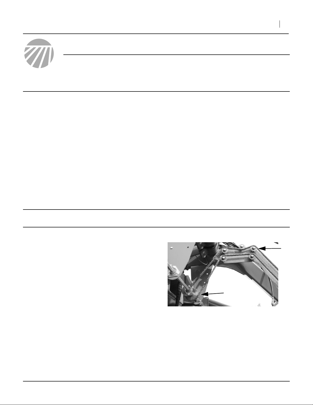
The contact drive wheel sprocket ➀ to be replaced is
located at the center of the planter, beneath the peak of
the overhead frame tubes.
Refer to Figure 1
1. Loosen idler ➁, and lift the drive chain off the old
sprocket ➀.
Note: Although this update can be performed with the
planter unfolded, it is much more complicated that
way. These instructions assume a folded planter.
If necessary, move the implement to a dry well-lighted
location suitable for disassembly.
Park and secure the implement. Secure the tractor if left
connected. Disconnect any hydraulic and electrical
power to the implement.
“Left” and “Right” are facing in the direction of machine
travel.
Have the following tools at hand:
• Basic hand tools (including an assortment of roll-pin
punches)
Also have an assistant for the wheel assembly portion of
this upgrade. Removing the old wheel and installing the
new wheel is not easily done by one person.
➁
➀
Figure 1
Remove Old Sprocket
©Copyright 2006 Printed 12/21/2006 401-465M
25146
2 Contact Drive Wheel Update Kit
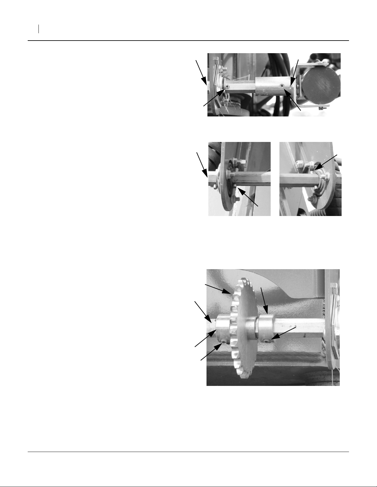
Refer to Figure 2
2. Drive out the roll pin ➀ that attaches the right side
drive shaft U-joint ➁ to the center drive shaft ➂.
Save the pin, unless also performing the drive shaft
update.
3. Slide the U-joint ➁ off the right end of the center
shaft ➂.
4. If a second pin ➃ is installed outside the bearing,
remove it as well. Save this pin.
Refer to Figure 3
5. If pins ➀➁ are present at the insides of the center
shaft brackets, remove and save them.
Refer to Figure 4
6. Loosen the set screws ➀ on the retaining collar ➁
to the right of the sprocket ➂ to be removed.
7. Slide the drive shaft ➃ to the left, until the locking
collar ➁, and then the sprocket ➂, are off the end of
the shaft. Save the locking collar. The old sprocket
is not reused.
Note: If it is not possible to slide the drive shaft ➃ far
enough to remove the collar and sprocket:
a. Mark the shaft location of the left collar ➄
b. Loosen that collar’s set screws ➅
c. Remove the sprocket and right collar (only)
➂
➂
➃
➁
Figure 2
Disconnect Right U-Joint
➁
Figure 3
Remove Pins
Great Plains Mfg., Inc.
➀
25142
➀
➂
25147
8. Slide the new sprocket, and then the locking collar
➁ onto the shaft. If it was necessary to loosen the
left collar ➄, re-position it to the mark and tighten its
set screws.
9. Re-insert the shaft ➃ through all bearings and
brackets.
10. Firmly slide the locking collar ➁ against the new
sprocket. Tighten its set screws.
11. Re-install any pins removed in steps 4 and 5.
➃
➄
Refer to Figure 1
12. Remount the chain.
13. Tighten idler ➂ (previous page) until there is3⁄4in
slack in the longest chain span.
14. Skip this next step if also installing the drive shaft
update.
15. Re-insert the roll pin in the right drive shaft universal joint.
➂
➅
➁
Figure 4
Loosen Collar
➀
➂
25148
401-465M 12/21/2006
 Loading...