

Page 1
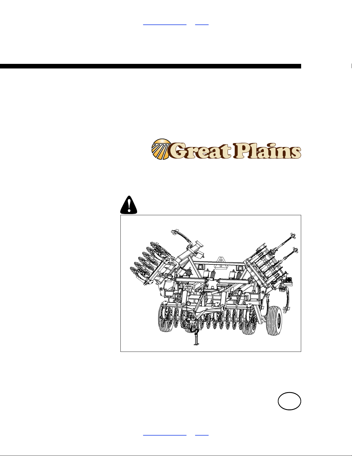
Table of Contents Index
41298
Operator Manual
5313, 5315, 5317, 5319, 5321 & 5323
Turbo-Chisel (S/N A1420X+)
5109, 5111, 5113 & 5115,
Manufacturing, Inc.
www.greatplainsmfg.com
Read the operator’s manual entirely. When you see this symbol, the
subsequent instructions and warnings are serious - follow without
exception. Your life and the lives of others depend on it!
Illustrations may show optional equipment not supplied with standard unit.
ORIGINAL INSTRUCTIONS
© Copyright 2018 Printed 2018-07-11 566-224M
Table of Contents Index
EN
Page 2

Machine Identification
Record your machine details in the log below. If you replace this manual, be sure to transfer this information to the new
manual.
If you or the dealer have added options not originally ordered with the machine, or removed options that were
originally ordered, the weights and measurements are no longer accurate for your machine. Update the record by
adding the machine weight and measurements with the option(s) weight and measurements.
Model Number
Serial Number
Machine Height
Machine Length
Machine Width
Machine Weight
Year of Construction
Delivery Date
First Operation
Accessories
Dealer Contact Information
Name:
Street:
City/State:
Telephone:
Email:
Dealer’s Customer
No.:
WARNING:
Cancer and Reproductive Harm - www.P65Warnings.ca.gov
Page 3

TC5109-5323 Cover Index Table of Contents iii
Table of Contents
Important Safety Information.................................................1
Safety Decals ....................................................................5
Introduction......................................................................10
Models Covered ..............................................................10
Description of Unit ...........................................................10
Document Family .....................................................10
Using This Manual....................................................10
Definitions.................................................................10
Owner Assistance............................................................11
Further Assistance ...................................................11
Preparation and Setup .........................................................12
Prior to Going to the Field Checklist................................12
Hitching Turbo-Chisel to Tractor......................................13
Electrical Hookup .....................................................14
Hydraulic Hose Hookup............................................14
Hydraulic Hose Hookup............................................14
Transport Locks........................................................15
First Time Field Adjustments...........................................15
Pre-Leveling of Machine...........................................15
Front to Rear Leveling..............................................15
Wing Adjustment (5313-5315)..................................16
Wing Adjustment (5317-5323) .................................16
5317-5323 Hydraulic Down Pressure ......................17
Operating Instructions.........................................................18
Pre-Start Checklist ..........................................................18
Transport .........................................................................19
Transport Steps........................................................19
Field Operation................................................................20
Field Set-Up Checklists ...................................................20
General Operation and In-Field Adjustments ..................20
Rear Attachment Settings ...............................................23
Rear Chopper Reel ..................................................23
Buster Bar ................................................................24
Maintenance and Lubrication..............................................25
Maintenance....................................................................25
Lubrication.......................................................................25
Appendix ...............................................................................27
TC Specifications and Capacities....................................27
Tire Inflation Chart...........................................................28
Hydraulic Connectors and Torque...................................28
Torque Values Chart .......................................................29
© Copyright 2006, 2007, 2008, 2009, 2010, 2011, 2012, 2013, 2014, 2015, 2016, 2017, 2018 All rights Reserved
Great Plains Manufacturing, Inc. provides this publication “as is” without warranty of any kind, either expressed or implied. While every precaution has been
taken in the preparation of this manual, Great Plains Manufacturing, Inc. assumes no responsibility for errors or omissions. Neither is any liability assumed
for damages resulting from the use of the information contained herein. Great Plains Manufacturing, Inc. reserves the right to revise and improve its products
as it sees fit. This publication describes the state of this product at the time of its publication, and may not reflect the product in the future.
Registered Trademarks of Great Plains Manufacturing, Inc. include: Air-Pro, Clear-Shot, Discovator, Great Plains, Land Pride, MeterCone,
Nutri-Pro, Seed-Lok, Solid Stand, Terra-Guard, Turbo-Chisel, Turbo-Chopper, Turbo-Max, Turbo-Till, Ultra-Till, Whirlfilter, and Yield-Pro.
Trademarks of Great Plains Manufacturing, Inc. include: AccuShot, Max-Chisel, Row-Pro,
Singulator Plus, Short Disk, Swath Command, Terra-Tine, Ultra-Chisel, and X-Press.
Brand and Product Names that appear and are owned by others are trademarks of their respective owners.
Printed in the United States of America
07/11/2018 Cover Index 566-224M
Page 4

TC5109-5323 Table of Contents Index iv
07/11/2018 Table of Contents Index 566-224M
Page 5
TC5109-5323 Table of Contents Index Important Safety Information 1
Important Safety Information
Look for Safety Symbol
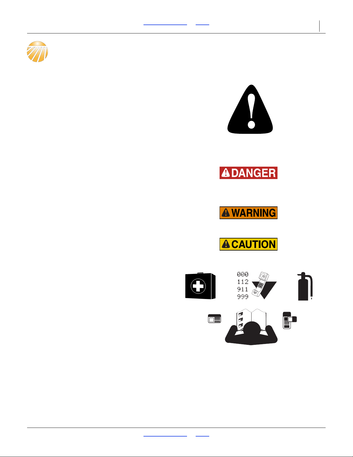
The SAFETY ALERT SYMBOL indicates there is a
potential hazard to personal safety involved and extra
safety precaution must be taken. When you see this
symbol, be alert and carefully read the message that
follows it. In addition to design and configuration of
equipment, hazard control and accident prevention are
dependent upon the awareness, concern, prudence and
proper training of personnel involved in the operation,
transport, maintenance and storage of equipment.
Be Aware of Signal Words
Signal words designate a degree or level of hazard
seriousness.
DANGER indicates an imminently hazardous situation
which, if not avoided, will result in death or serious injury.
This signal word is limited to the most extreme situations,
typically for machine components that, for functional
purposes, cannot be guarded.
WARNING indicates a potentially hazardous situation
which, if not avoided, could result in death or serious
injury, and includes hazards that are exposed when
guards are removed. It may also be used to alert against
unsafe practices.
CAUTION indicates a potentially hazardous situation
which, if not avoided, may result in minor or moderate
injury. It may also be used to alert against unsafe
practices.
Prepare for Emergencies
Be prepared if a fire starts
Keep a first aid kit and fire extinguisher handy.
Keep emergency numbers for doctor, ambulance, hospital
and fire department near phone.
Be Familiar with Safety Decals
Read and understand “Safety Decals” on page 5,
thoroughly.
Read all instructions noted on the decals.
Keep decals clean. Replace damaged, faded and illegible
decals.
07/11/2018 Table of Contents Index 566-224M
Page 6
TC5109-5323 Table of Contents Index Important Safety Information 2
Use Safety Chains
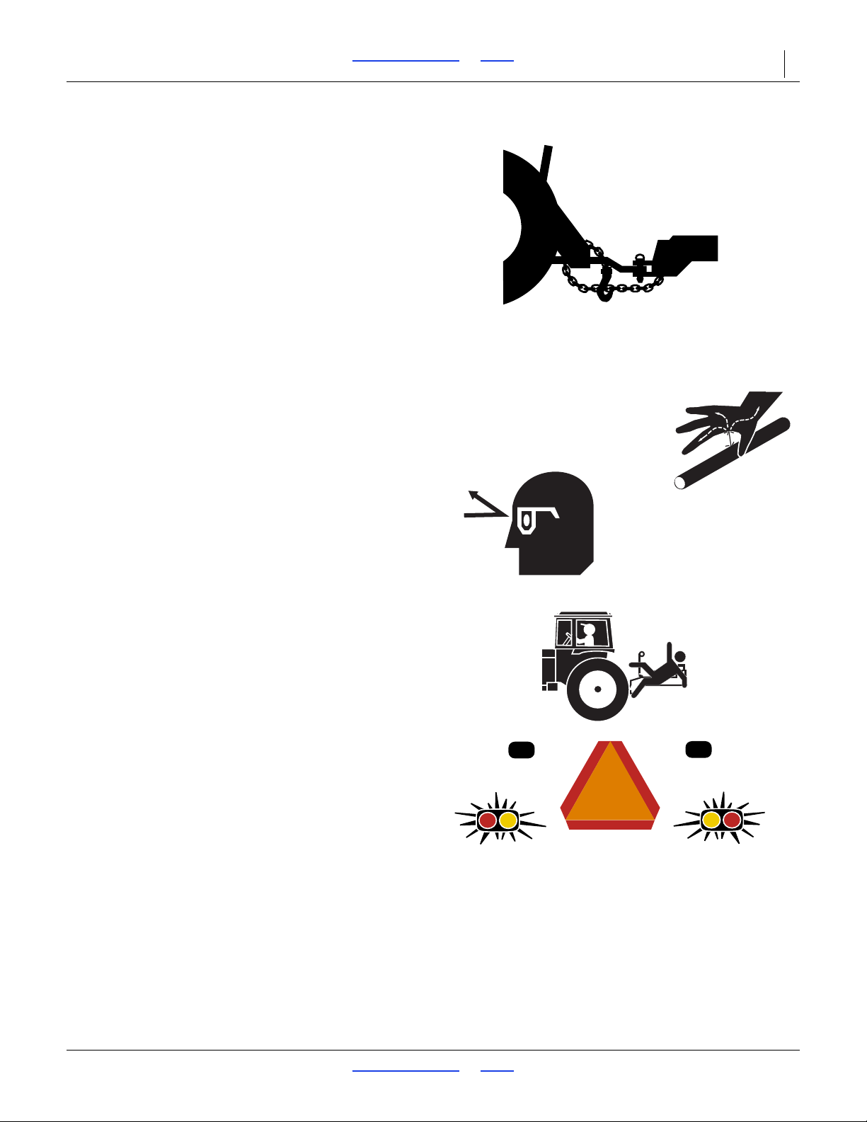
Use safety chains to help control drawn machinery should
it separate from tractor draw-bar or trailing nurse tank
hitch.
Use chain with a strength rating equal to or greater than
the gross weight of towed machinery.
Attach implement chain to tractor draw-bar support or
specified anchor location. Allow only enough slack in
chain for turns.
Replace chain if any links or end fittings are broken,
stretched or damaged.
Do not use safety chain for towing.
Avoid High Pressure Fluids
Escaping fluid under pressure can penetrate the skin,
causing serious injury. This Turbo-Chisel requires a
Power-Beyond port, which is always under pressure
when the tractor is running.
Avoid the hazard by relieving pressure at other remote,
and shutting down tractor before connecting,
disconnecting or inspecting hydraulic lines.
Use a piece of paper or cardboard, NOT BODY PARTS, to
check for suspected leaks.
Wear protective gloves and safety glasses or goggles when
working with hydraulic systems.
If an accident occurs, seek immediate medical assistance
from a physician familiar with this type of injury.
Keep Riders Off Machinery
Riders obstruct the operator’s view. Riders could be
struck by foreign objects or thrown from the machine.
Never allow children to operate equipment.
Keep all bystanders away from machine during operation.
Use Safety Lights and Devices
Slow-moving tractors and towed implements can create
a hazard when driven on public roads. They are difficult
to see, especially at night.
Use flashing warning lights and turn signals whenever
driving on public roads.
Use lights and devices provided with implement.
07/11/2018 Table of Contents Index 566-224M
Page 7
TC5109-5323 Table of Contents Index Important Safety Information 3
Transport Machinery Safely
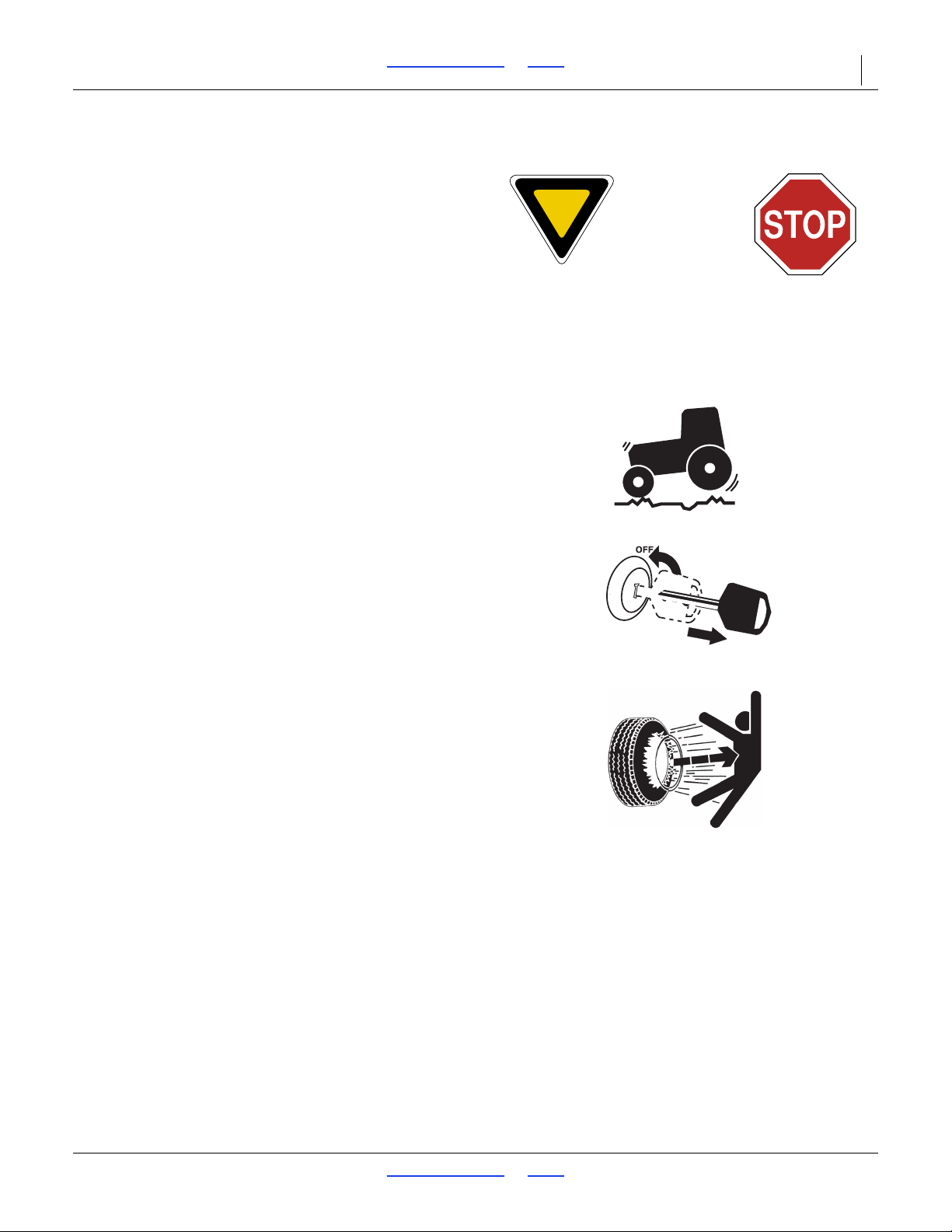
Maximum transport speed for implement is 20 mph (32
kph), 13 mph (22 kph) in turns. Some rough terrains
require a slower speed. Sudden braking can cause a
towed load to swerve and upset.
Do not tow an implement or nurse tank that weighs more
than 1.5 times the weight of towing vehicle.
Carry reflectors or flags to mark Turbo-Chisel in case of
breakdown on the road.
Keep clear of overhead power lines and other
obstructions when transporting. Refer to transport
dimensions under “TC Specifications and Capacities” on
page 27.
Do not exceed 20 mph. Never travel at a speed which does
not allow adequate control of steering and stopping.
Reduce speed if towed load is not equipped with brakes.
Reduce speed on rough roads.
Comply with national, regional and local laws.
Do not fold or unfold the Turbo-Chisel while the tractor is
moving.
Shutdown and Storage
Lower Turbo-Chisel, put tractor in park, turn off engine,
and remove the key.
Secure Turbo-Chisel using parking jack provided.
Detach and store Turbo-Chisel in an area where children
normally do not play.
Tire Safety
Tire changing can be dangerous. Employ trained
personnel using correct tools and equipment.
When inflating tires, use a clip-on chuck and extension
hose long enough for you to stand to one side–not in front
of or over tire assembly. Use a safety cage if available.
When removing and installing wheels, use wheel-handling
equipment adequate for weight involved.
07/11/2018 Table of Contents Index 566-224M
Page 8
TC5109-5323 Table of Contents Index Important Safety Information 4
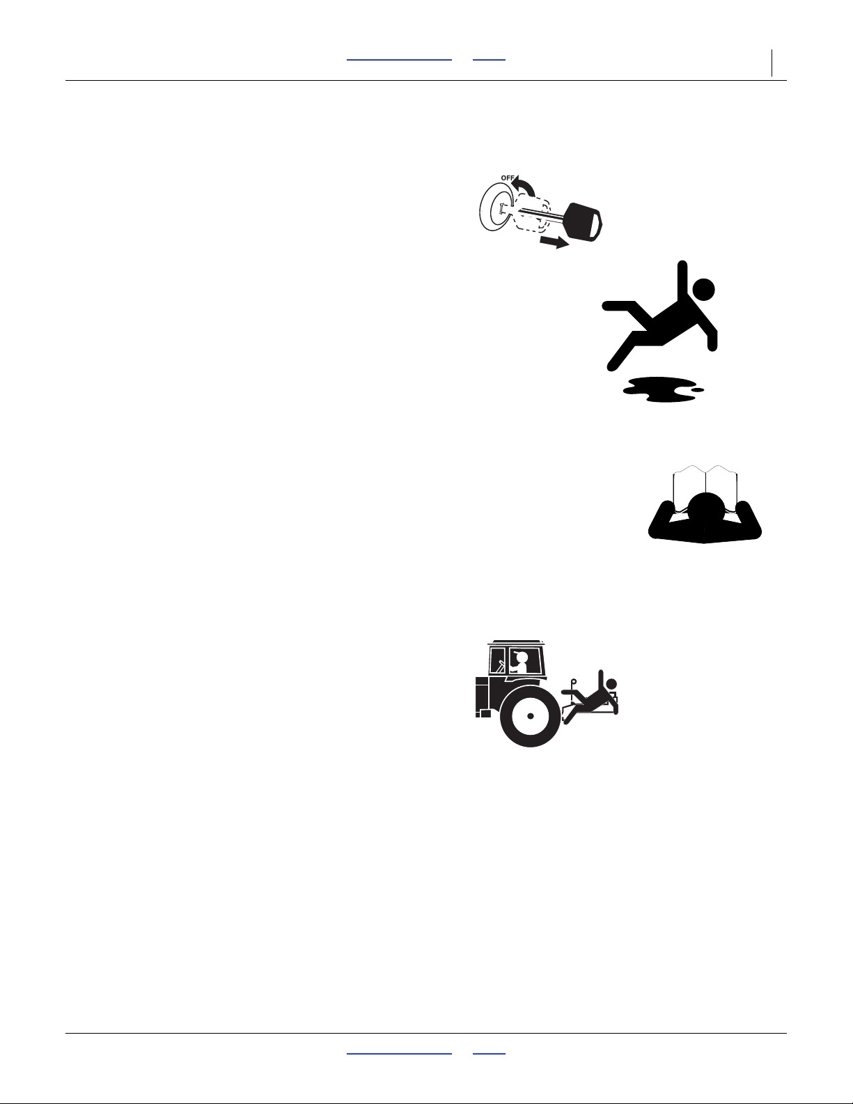
Practice Safe Maintenance
Understand procedure before doing work. Use proper
tools and equipment. Refer to this manual for additional
information.
Work in a clean, dry area.
Lower implement, put tractor in park, turn off engine,
and remove key before performing maintenance.
Make sure all moving parts have stopped and all system
pressure is relieved.
Disconnect battery ground cable (-) before servicing or
adjusting electrical systems or before welding on TurboChisel.
Inspect all parts. Make sure parts are in good condition
and installed properly.
Remove buildup of grease, oil or debris.
Remove all tools and unused parts from implement
before operation.
Safety At All Times
Thoroughly read and understand the instructions in this
manual before operation. Read all instructions noted on
the safety decals.
Be familiar with all Turbo-Chisel functions.
Operate machinery from the driver’s seat only.
Do not leave Turbo-Chisel unattended with tractor engine
running.
Do not stand between tractor and implement, or
implement and nurse tank, during hitching.
Keep hands, feet and clothing away from power-driven
parts.
Wear snug-fitting clothing to avoid entanglement with
moving parts.
Watch out for wires, trees, etc., when folding and raising
Turbo-Chisel. Make sure all persons are clear of working
07/11/2018 Table of Contents Index 566-224M
Page 9
TC5109-5323 Table of Contents Index Important Safety Information 5
41194
42730
Safety Decals
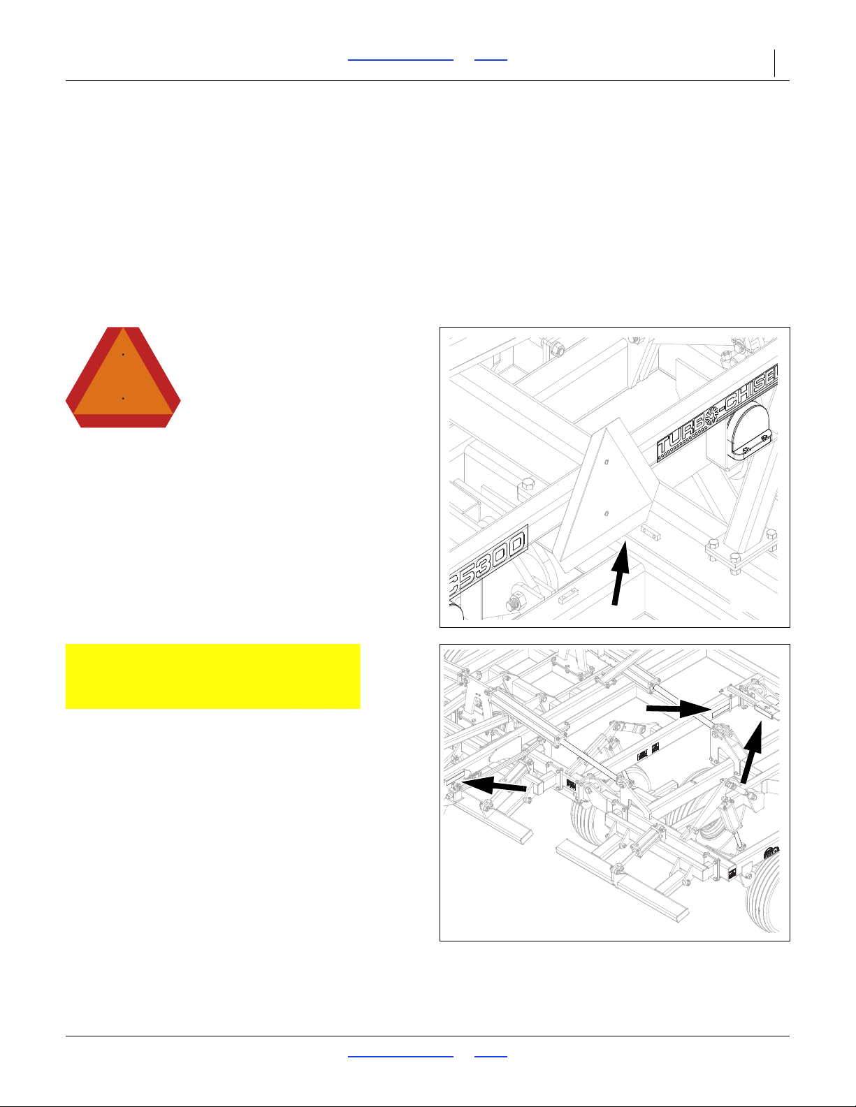
Safety Reflectors and Decals
Your implement comes equipped with all lights, safety
reflectors and decals in place. They were designed to
help you safely operate your implement.
Read and follow decal directions.
Keep lights in operating condition.
Keep all safety decals clean and legible.
Replace all damaged or missing decals. Order new decals
from your Great Plains dealer. Refer to this section for
818-055C
Slow Moving Vehicle Reflector
On the back of smv post on wing stop;
1 total
proper decal placement.
When ordering new parts or components, also request
corresponding safety decals.
To install new decals:
1. Clean the area on which the decal is to be placed.
2. Peel backing from decal. Press firmly on surface,
being careful not to cause air bubbles under decal.
838-615C
Amber Reflectors
Two on front of light brackets. Two on front, outside of
trusses. Two on outside, rear of center frame. Two on
rear of finishing attachment (not shown), visible from side
while folded for transport;
8 total
07/11/2018 Table of Contents Index 566-224M
Page 10
TC5109-5323 Table of Contents Index Important Safety Information 6
41193
41193
41189
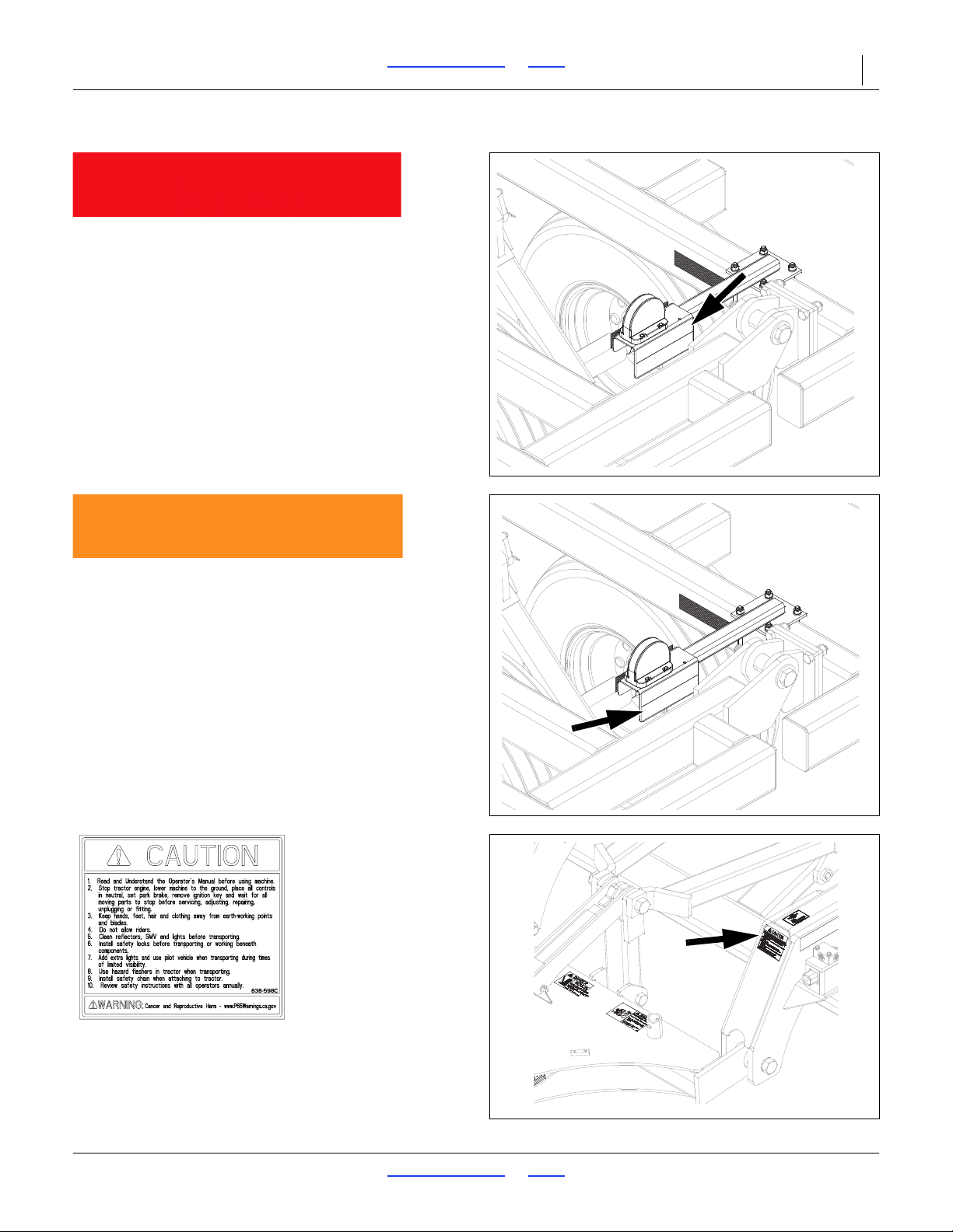
838-614C
Red Reflectors
On rear of light brackets (top). On rear of reflector
bracket (top), Models 5111, 5113, 5115 Only;
2 or 4 total
838-603C
Orange Reflectors
On rear of light brackets (bottom) On rear of reflector
bracket (bottom), Models 5111, 5113, 5115 Only;
2 or 4 total
838-598C
Caution: Read Operator’s Manual
On front of left truss;
1 total
07/11/2018 Table of Contents Index 566-224M
Page 11
TC5109-5323 Table of Contents Index Important Safety Information 7
41189
41188
42730
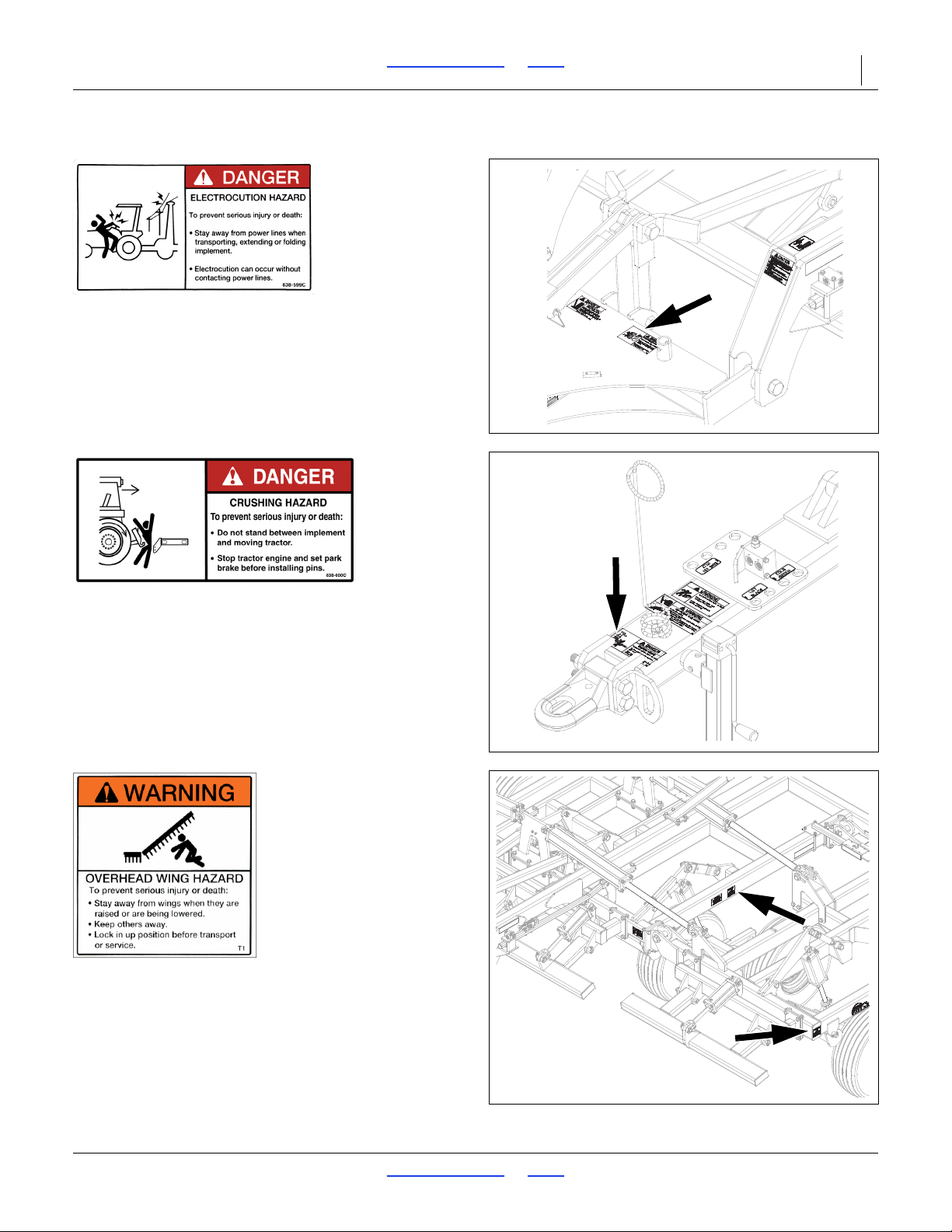
838-599C
Danger: Electrocution Hazard
Top side of gusset on rear of hitch (left side), Models
5313-5323;
1 total
838-600C
Danger: Crushing Hazard
Front of hitch;
1 total
838-602C
Warning: Overhead Wing Hazard
Outside, center of center frame and front, left of wing
frames (both sides), Models 5313-5323;
4 total
07/11/2018 Table of Contents Index 566-224M
Page 12
TC5109-5323 Table of Contents Index Important Safety Information 8
41188
42729
42729
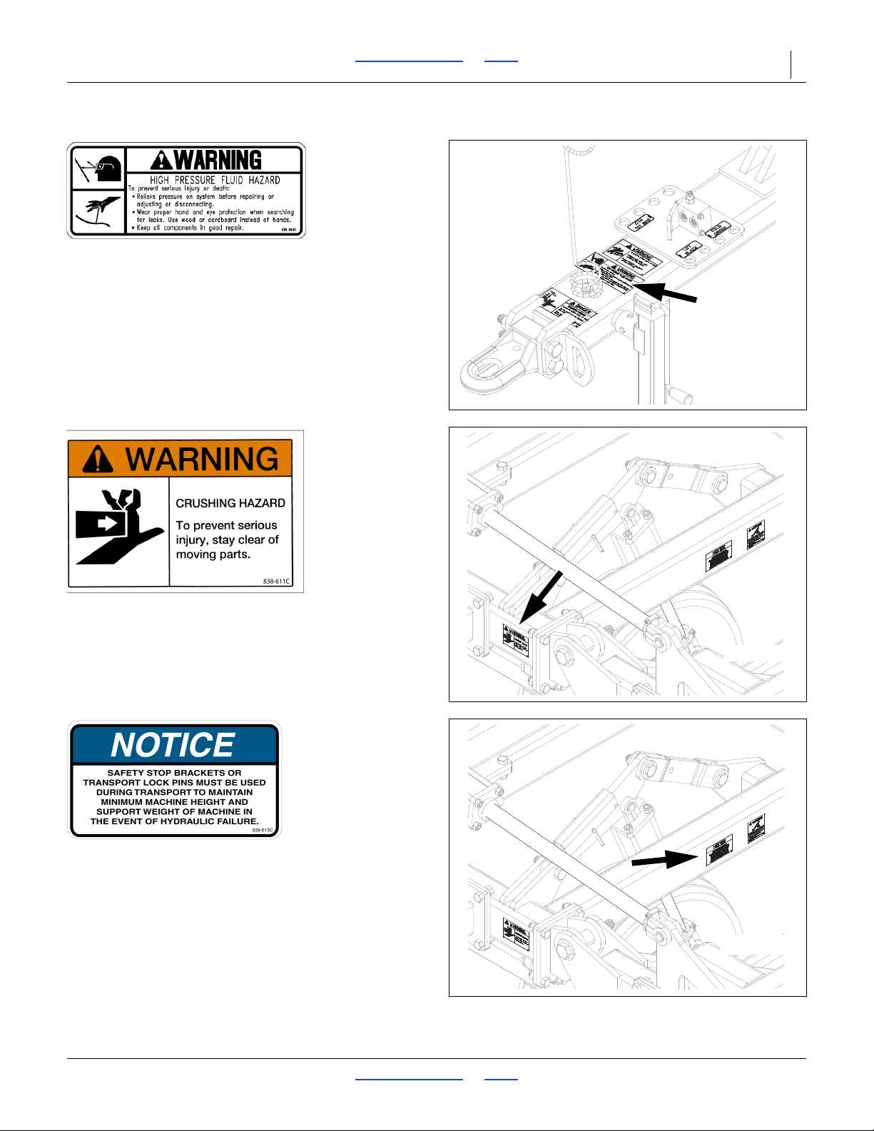
838-094C
Warning: High Pressure Fluid
Front of hitch (middle);
1 total
838-611C
Warning: Hand Crushing
Front side of center frame (left & right side);
2 total
838-613C
Notice: Transport Lock
Outside of cylinder mount bar (both sides);
2 total
07/11/2018 Table of Contents Index 566-224M
Page 13
TC5109-5323 Table of Contents Index Important Safety Information 9
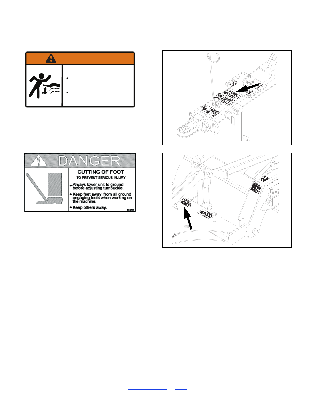
838-606C
To prevent serious injury or death:
Tongue rises rapidly when
unhitched from tractor.
Lower implement to ground
before unhitching.
WARNING
41188
41189
838-606C
Warning: Tongue Rising
Front of hitch (rear);
1 total
848-271C
Danger: Cutting Of Foot
Top side of gusset on rear of hitch (middle);
1 total
07/11/2018 Table of Contents Index 566-224M
Page 14
TC5109-5323 Table of Contents Index Important Safety Information 10
R
L
Figure 1
Turbo Chisel
42050
U
D
F
B
L
R
U
D
F
B
L
R
Introduction
Great Plains welcomes you to our growing family of new
product owners. The TC5109-5323 have been designed
with care and built by skilled workers using quality
materials. Proper setup, maintenance, and safe
operating practices will help you get years of satisfactory
use from the machine.
Models Covered
TC5109 11-Foot 1-section
TC5111 14-Foot 1-section
TC5113 16-Foot 1-section
TC5115 19-Foot 1-section
TC5313 16-Foot 3-section
TC5315 19-Foot 3-section
TC5317 21-Foot 3-section
TC5319 24-Foot 3-section
TC5321 26-Foot 3-section
TC5323 29-Foot 3-section
Description of Unit
The TC5109-5323 is a one or three-section “vertical”
tillage tool. Working width ranges from 11 to 29 feet. The
implement is designed to cut, size and bury residue. It
can work up to 11” deep, will dislodge rootballs and leave
the field smooth enough for “one pass” finishing in
Spring. For optimum leveling of your machine, it should
be equipped with either a Chopper Reel or Buster Bar
attachment.
Document Family
566-224Q-ENG Assembly Manual
566-224Q Pre-Delivery Manual
566-224M Operator Manual (this document)
566-224P Parts Manual
Using This Manual
This manual will familiarize you with
safety, assembly, operation,
adjustments, troubleshooting, and
maintenance. Read this manual and
follow the recommendations to help
ensure safe and efficient operation.
The information in this manual is current at printing.
Some parts may change to assure top performance.
Definitions
The following terms are used throughout this manual.
A crucial point of information related to the preceding topic.
Read and follow the directions to remain safe, avoid serious
damage to equipment and ensure desired field results.
Useful information related to the preceding topic.
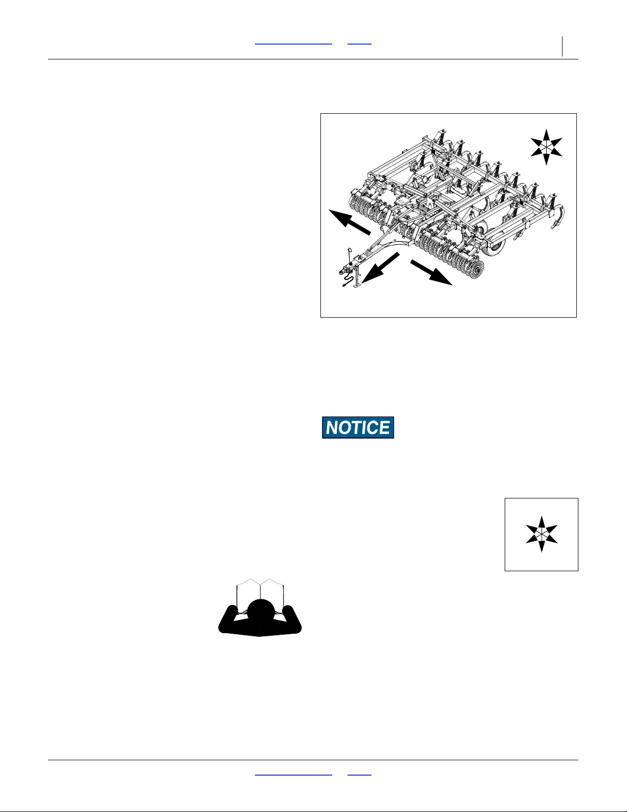
Right-hand and left-hand as used in this
manual are determined by facing the
direction the machine will travel while in
use unless otherwise stated. An orientation
rose in some line art illustrations shows the
directions of: Up, Back, Left, Down, Front,
Right.
07/11/2018 Table of Contents Index 566-224M
Page 15
TC5109-5323 Table of Contents Index Important Safety Information 11
Figure 2
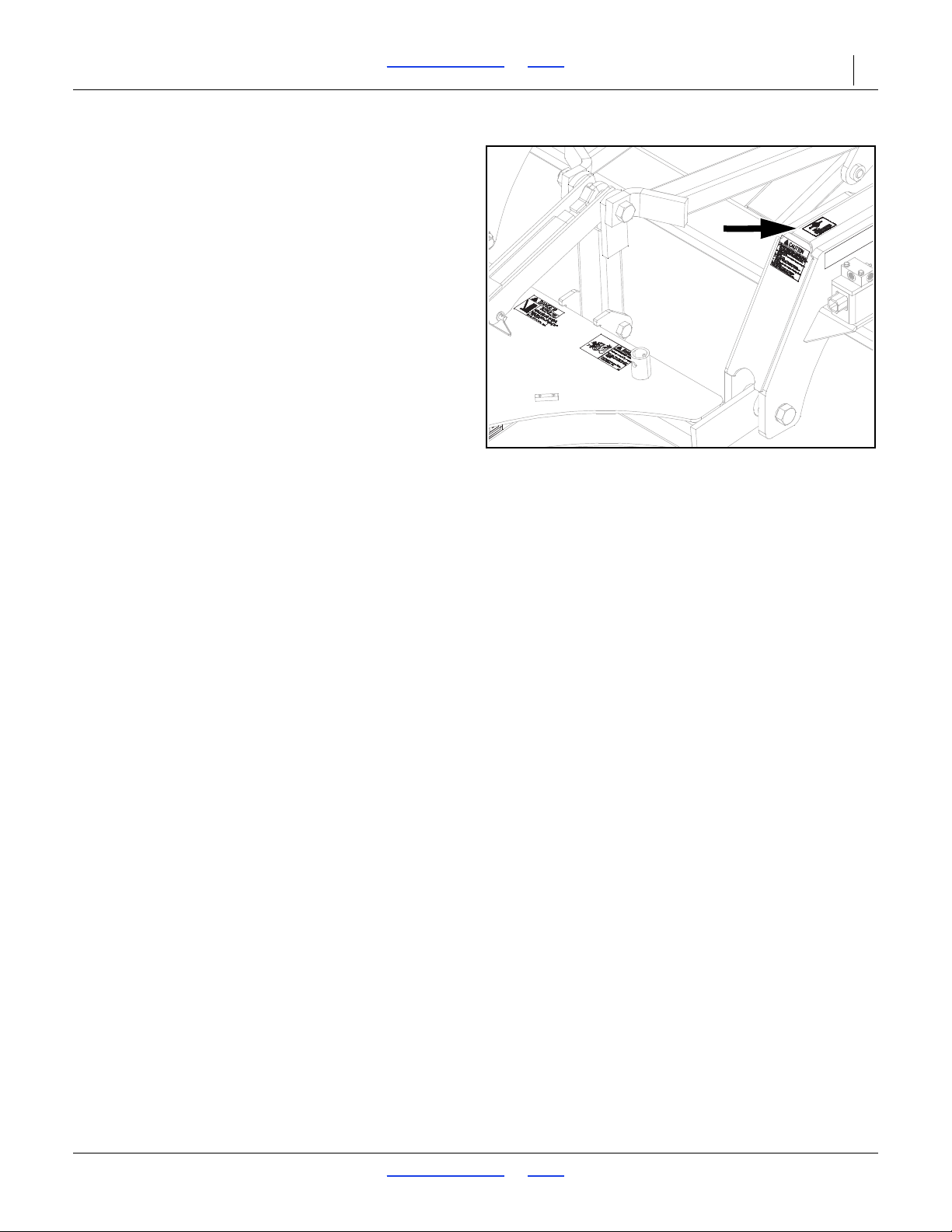
Serial Number Plate
41189
Owner Assistance
If you need customer service or repair parts, contact a
Great Plains dealer. They have trained personnel, repair
parts and equipment specially designed for Great Plains
products.
Refer to Figure 2
Your machine’s parts were specially designed and
should only be replaced with Great Plains parts. Always
use the serial and model number when ordering parts
from your Great Plains dealer. The serial-number plate is
located on the left end of the top front tool bar.
Record your Turbo-Chisel model and serial number here
for quick reference:
Model Number:__________________________
Serial Number: __________________________
Your Great Plains dealer wants you to be satisfied with
your new machine. If you do not understand any part of
this manual or are not satisfied with the service received,
please take the following actions.
1. Discuss the matter with your dealership service
manager. Make sure they are aware of any problems
so they can assist you.
2. If you are still unsatisfied, seek out the owner or
general manager of the dealership.
Further Assistance
Great Plains Manufacturing, Inc. wants you to be
satisfied with your new Turbo Chisel. If for any reason
you do not understand any part of this manual or are
otherwise dissatisfied with the product please contact:
Great Plains Service Department
1525 E. North St.
PO Box 5060
Salina, KS 67402-5060
Or go to www.greatplainsag.com and follow the contact
information at the bottom of your screen for our service
department.
(800)255-9215
07/11/2018 Table of Contents Index 566-224M
Page 16

TC5109-5323 Table of Contents Index Preparation and Setup 12
Preparation and Setup
This section helps you prepare your tractor and TurboChisel for use, and covers tasks that need to be done
seasonally, or when the tractor/Turbo-Chisel configuration
changes.
Before using the Turbo-Chisel in the field, you must hitch
it to a suitable tractor, inspect systems and level the
Turbo-Chisel. Before using the Turbo-Chisel for the first
time, and periodically thereafter, certain adjustments and
calibrations are required.
Prior to Going to the Field Checklist
Complete this checklist before routine setup:
Read and understand “Important Safety
Information” on page 1.
Check that all working parts are moving freely, bolts
are tight, and cotter pins are spread.
Make sure your tractor horsepower matches the
implement you are pulling. This is important so the
implement can do the best possible job.
Clean all hydraulic couplings and connect to tractor
as shown on page 13 and 14.
If machine is folded, remove the transport pins from
wing stops. (DO NOT remove pins if the wing is
leaning against the pins or putting pressure on the
pins. Use the hydraulics to pull the wings in
completely before unpinning them.) Once the pins
are removed, slowly untold the unit. Make sure no
one is under the wings during the unfolding process.
Check again for hydraulic leaks and watch that
hoses do not get pinched in hinges, wing stops, etc.
After the machine is completely unfolded, raise and
lower the Turbo Chisel several times to purge air
from the hydraulic system. Again check for hydraulic
leaks and tighten or replace if necessary.
Check safety chain hookup. Make sure all warning
lights are hooked up and functioning correctly.
Check that all grease fittings are in place and
lubricated. See “Lubrication” on page 25. The hubs
will come pre-greased and will not need greased at
this time.
Check that all safety decals and reflectors are
correctly located and legible. Replace if damaged.
See “Safety Decals” on page 5.
Inflate tires to pressure recommended and tighten
wheel bolts as specified. See “Torque Values
Chart” on page 29.
Put transport locks in place and refold the machine
slowly. Put wing stop pins in place. Always use the
transport pins when moving from field to field. You
are now ready to go to the field.
07/11/2018 Table of Contents Index 566-224M
Page 17
TC5109-5323 Table of Contents Index Preparation and Setup 13
1
2
Figure 3
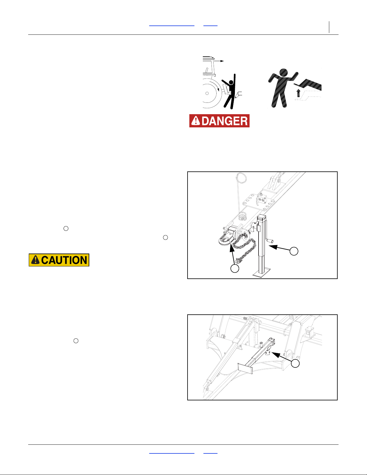
Jack & Hitch Clevis
41993
Crushing Hazard:
Do not stand or place any body part between turbo-chisel and
moving tractor. You may be severely injured or killed by being
crushed between the tractor and turbo-chisel. Stop tractor
engine and set parking brake before attaching cables and
hoses.
1
2
3
Figure 4
Jack in Storage
41994
3
Hitching Turbo-Chisel to Tractor
Hitch to a tractor for highway transport or field
operations. Hitch to a leading implement only for field
operations. Do not transport behind another implement.
Before hitching, check the compatibility and capability of
the towing tractor or implement:
The TC5109-5323 Turbo-Chisel is a pull-type implement
equipped with a standard Category IV single tang hitch.
It may be converted to a Category III or clevis hitch using
supplied accessory parts.
To prevent soil compaction on rows, set tractor wheels
between rows. For hillsides and steep slopes, set tractor
wheels as wide as possible for maximum stability.
1. Raise tractor three-point arms (if equipped) clear up
to clear Turbo-Chisel.
2. For TWO-WHEEL DRIVE and MFWD tractors, pin
drawbar in fixed center position for field and
transport. For FOUR-WHEEL DRIVE and TRACDRIVE tractors, leave one hole clearance on each
side of drawbar for field position, hitch damage may
occur if pinned solid. Pin in center position for
transport to maintain maximum steering control.
Refer to Figure 3
3. Use jack to raise and lower turbo-chisel tongue.
4. Back tractor draw bar into alignment with hitch .
5. Secure with a locking hitch pin.
Negative Tongue Weight Hazard:
Make certain that turbo-chisel is securely hitched to the
tractor or leading implement before unfolding. An unhitched
turbo-chisel can tip over backwards during folding and
unfolding if the tongue is not secured.
6. Secure safety chain to an anchor on the tractor.
Refer to Figure 4
7. Retract jack foot. Re-orient jack to storage position.
8. After hitching tractor to turbo-chisel, store jack on
storage stob on Turbo-Chisel tongue.
Load Sway Hazard:
9. Lock drawbar swing to center position to minimize any
side-to-side sway to assure proper tracking in the field,
and safe road travel. See “Transport” on page 19, for
safe transporting.
07/11/2018 Table of Contents Index 566-224M
Page 18
TC5109-5323 Table of Contents Index Preparation and Setup 14
Figure 5
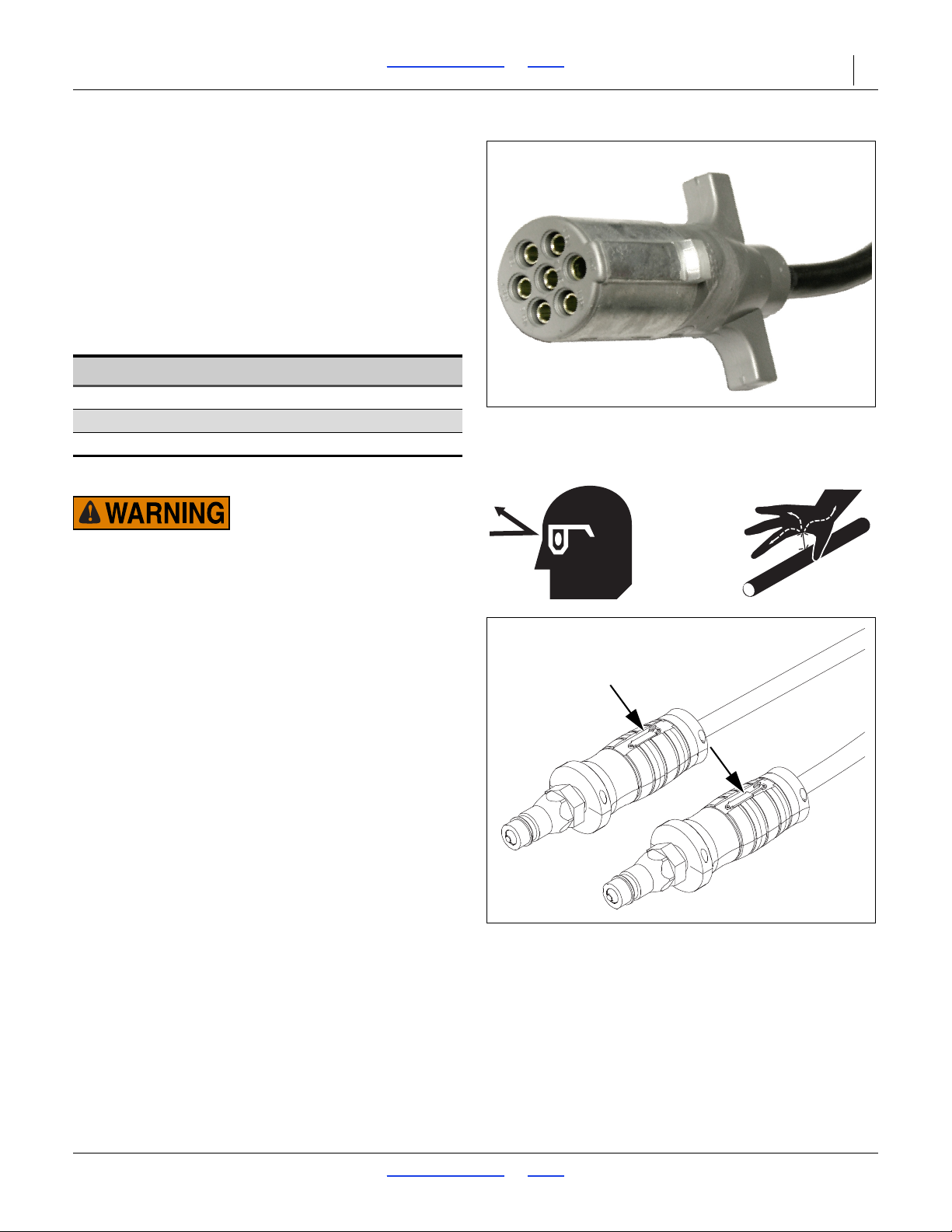
North American Connector
25236
Figure 6
Hose Handles
31733
Electrical Hookup
Refer to Figure 5
Your Turbo-Chisel is equipped with either North
American lights.
Plug the lighting connector into the tractor outlet.
Test the lights and signaling prior to highway movement.
Hydraulic Hose Hookup
Great Plains hydraulic hoses are color coded to help you
hookup hoses to your tractor outlets. Hoses that go to
the same remote valve are marked with the same color.
Color Hydraulic Function
Black Lift (2 hoses)
Green Fold (2 hoses)
Red Gang (2 hoses)
Hydraulic Hose Hookup
High Pressure Fluid Hazard:
Shut down tractor before making hydraulic connections.
Only trained personnel should work with system hydraulics.
Escaping fluid under pressure can have sufficient pressure to
penetrate the skin causing serious injury. If an accident
occurs, seek immediate medical assistance from a physician
familiar with this type of injury.
Use paper or cardboard, NOT BODY PARTS, to check for
leaks. Wear protective gloves and safety glasses or goggles
when working with hydraulic systems.
Refer to Figure 6
To distinguish hoses on the same hydraulic circuit, refer
to hose label.
• The hose with an extended-cylinder symbol feeds a
cylinder base end.
• The hose with a retracted-cylinder symbol feeds a
cylinder rod end.
Secure hoses and cables so that they have sufficient
slack for hitch movements, but cannot get caught
between moving parts of tractor, turbo-chisel or hitch.
Failure to safely route and secure hoses and cables
could result in damage requiring component repair/
replacement, and lost field time.
To distinguish hoses on the same hydraulic circuit, refer
to, “Hydraulic Hose Hookup” on page 14. Clean all
hydraulic couplings and hook hoses to tractor.
07/11/2018 Table of Contents Index 566-224M
Page 19
TC5109-5323 Table of Contents Index Preparation and Setup 15
1
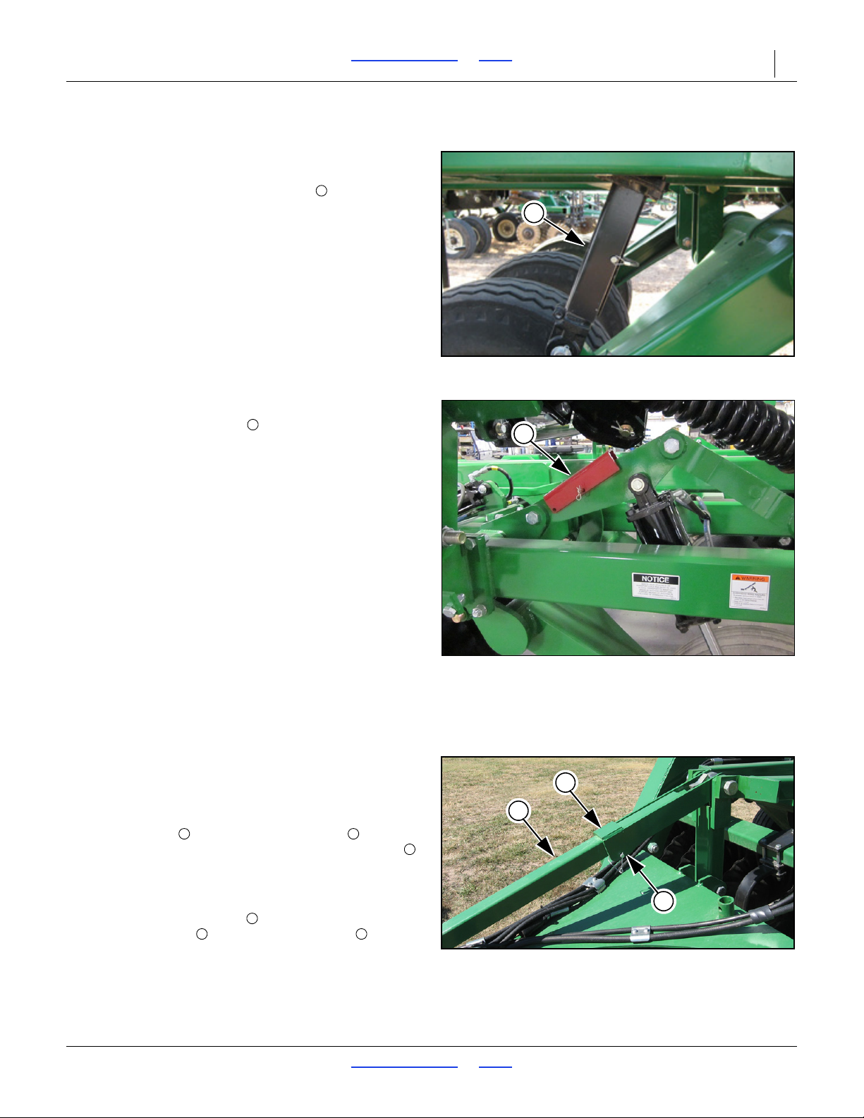
Figure 7
Transport Locks
41981
1
2
Figure 8
Transport Locks Storage
42673
2
1
2
3
Figure 9
Hitch Turnbuckle Adjustment
41805
12323
1
Transport Locks
Refer to Figure 7
10. Once the cylinders are connected, raise the unit
completely. If the transport locks are in place,
remove them at this time.
Refer to Figure 8
11. Store the transport locks on the lift mechanism link
as shown.
12. Once the locks are removed, unfold the wings (if
folding unit).
Make sure no one is under the wings during the
unfolding process. Watch for leaks and make sure
hoses do not get pinched during the initial unfolding
process.
13. Once the machine is unfolded, raise and lower the
machine several times to purge air from the lift
system. Again, watch for any leaks and tighten if
necessary.
14. Check the tire pressure for proper inflation and
check the tightness of lug bolts.
First Time Field Adjustments
Pre-Leveling of Machine
Pre-leveling of machine should be done on a good
level surface.
Front to Rear Leveling
Refer to Figure 9
15. Lower the machine until the front row of shanks are 1
to 2” above the surface. At this point, remove the
snap wire pin from the turnbuckle lock , swing
lock off turnbuckle and adjust the hitch turnbuckle
to adjust the fore and aft. The front corner of the
main frame should be
corner.
16. Now the turnbuckle lock may be swung back onto
hitch turnbuckle and the snap wire pin may be
re-installed.
07/11/2018 Table of Contents Index 566-224M
1
2 to 1” lower than the rear
Page 20
TC5109-5323 Table of Contents Index Preparation and Setup 16
2
2
1
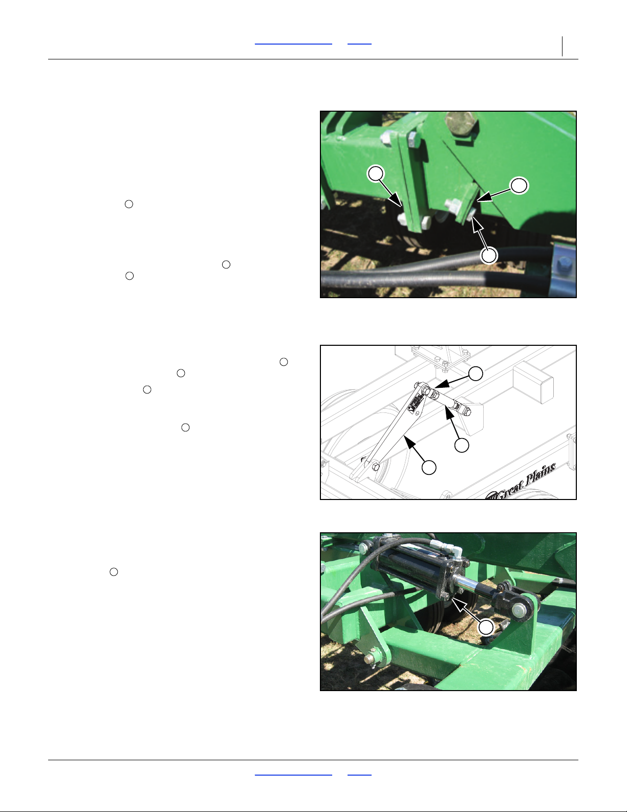
Figure 10
5313-5315 Wing Adjustment
42051
2
1
2
3
5
4
Figure 11
5317-5323 Wing Adjustment
42052
345
5
Figure 12
Gang Cylinder Purging
41983
6
6
Wing Adjustment (5313-5315)
Refer to Figure 10
17. Once the machine is level fore to aft, the wings may
be leveled (Models 5313-5315). Start by unfolding
the wings to a rigid position.
18. Completely extend the wing fold cylinders and check
the wings for levelness. If machine is not level, fold
wings back up and instal shims as needed to level.
Extra shims are stored in manual pak. The extra
shims may be needed in the future if the hinge holes
or bolts begin to wear. There are two different
thickness of shims, you may use multiple shims to
level wings.
19. Remove the two
more shims to raise wings or take shims out to
lower wings.
20. Re-install bolts and tighten to specs, see “Tor q ue
Values Chart” on page 29.
3
8 x 112 bolts and either add
Wing Adjustment (5317-5323)
Refer to Figure 11
21. The wings are to be leveled with the turnbuckle on
the wing cylinder mount .
22. Loosen jam nut and either shorten turnbuckle to
raise the wings or lengthen the turnbuckle to lower
the wings.
23. Re-tighten the jam nut to specs, see “Torque
Values Chart” on page 29.
Refer to Figure 12
24. Once machine is pre-leveled, raise and lower the
gangs completely to cycle and purge air from these
cylinders .
07/11/2018 Table of Contents Index 566-224M
Page 21
2
1
4
3
U
D
F
B
L
R
Figure 13
5317-5323 Down Pressure
41296
4
Figure 14
Down Pressure Decal
848-390C
12331
1
2
2
2
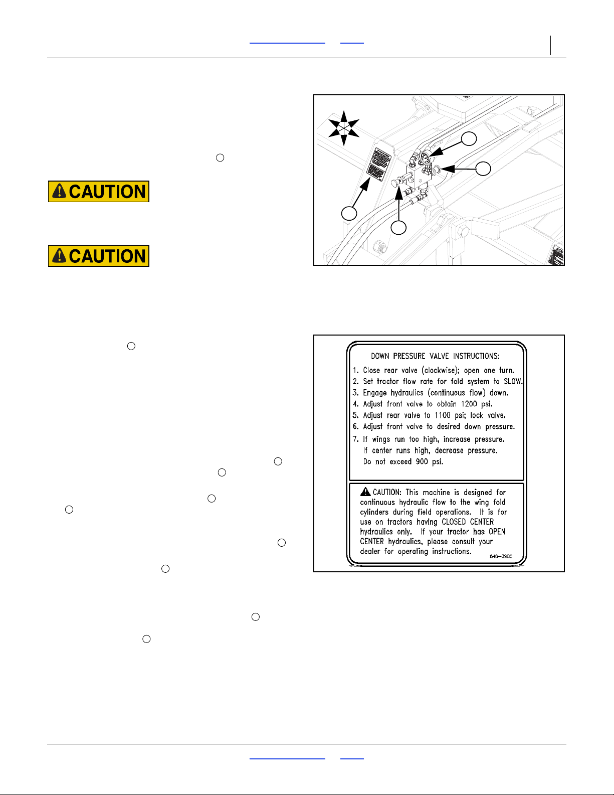
TC5109-5323 Table of Contents Index Preparation and Setup 17
5317-5323 Hydraulic Down Pressure
Refer to Figure 13
This setup procedure is for tractors with closed-center
or pressure compensated flow hydraulic systems.
Open center hydraulics not supported.Adjust down
pressure valve as shown on decal (located on front
right hand truss), Refer to Figure 14.
Never leave tractor valve centered when unfolded with
machine in motion. Machine damage may occur when wings
flex up or down
This machine is designed for continuous hydraulic flow to the
wing fold cylinders during field operations. It is for use on
tractors having CLOSED CENTER hydraulics only. If your
tractor has an OPEN CENTER hydraulics, please consult your
dealer for operating instructions.
25. Adjust the bypass/pressure reducing valve by
turning knob clockwise all the way in and then
backing out 1 full turn.
26. On tractor, adjust flow-control valve to low side of
flow rate.
The faster the flow of oil through the system the
greater the potential for oil heating, premature wear or
tractor damage.
27. Lock the fold hydraulic lever for continuous
downward oil flow.
28. Adjust bypass/pressure reducing valve knob on
implement so the pressure gauge reads 1200 psi.
Never exceed 1400 psi.
29. While watching pressure gauge , slowly open knob
until gauge reads 1100psi. Pressure might rise
and then fall off as knob is opened. If pressure
exceeds 1400 psi during this step, the tractor flow is
too high, reduce tractor flow. Lock valve knob at
1100 psi .
30. Finally adjust valve to the desired wing down
pressure setting. Never exceed 900 psi.
31. In field operation, lock the fold hydraulic lever for
continuous downward oil flow. If wings are running
too high, increase pressure setting, knob , to level
machine. If center is too high, decrease pressure
setting with knob on valve.
07/11/2018 Table of Contents Index 566-224M
Page 22

TC5109-5323 Table of Contents Index Operating Instructions 18
High Pressure Fluid Hazard:
Relieve pressure and shut down tractor before connecting,
disconnecting or checking hydraulic lines. Use a piece of
paper or cardboard, NOT BODY PARTS, to check for leaks.
Wear protective gloves and safety glasses or goggles when
working with hydraulic systems. Escaping fluid under pressure
can have sufficient pressure to penetrate the skin causing
serious injury. If an accident occurs, seek immediate medical
assistance from a physician familiar with this type of injury.
Operating Instructions
This section covers general operating procedures.
Experience, machine familiarity, and the following
information will lead to efficient operation and good
working habits. Always operate farm machinery with
safety in mind.
Pre-Start Checklist
Perform the following steps before transporting the
Turbo-Chisel to the field.
Carefully read “Important Safety Information” on
page 1.
Lubricate Turbo-Chisel as indicated under
“Lubrication” on page 25.
Check all tires for proper inflation, “Tire Inflation
Chart” on page 28.
Check all bolts, pins, and fasteners. Torque as
shown in “Torque Values Chart” on page 29.
Check Turbo-Chisel for worn or damaged parts.
Repair or replace parts before going to the field.
Check hydraulic hoses, fittings, and cylinders for leaks.
Repair or replace before going to the field.
07/11/2018 Table of Contents Index 566-224M
Page 23
TC5109-5323 Table of Contents Index Operating Instructions 19
Transport
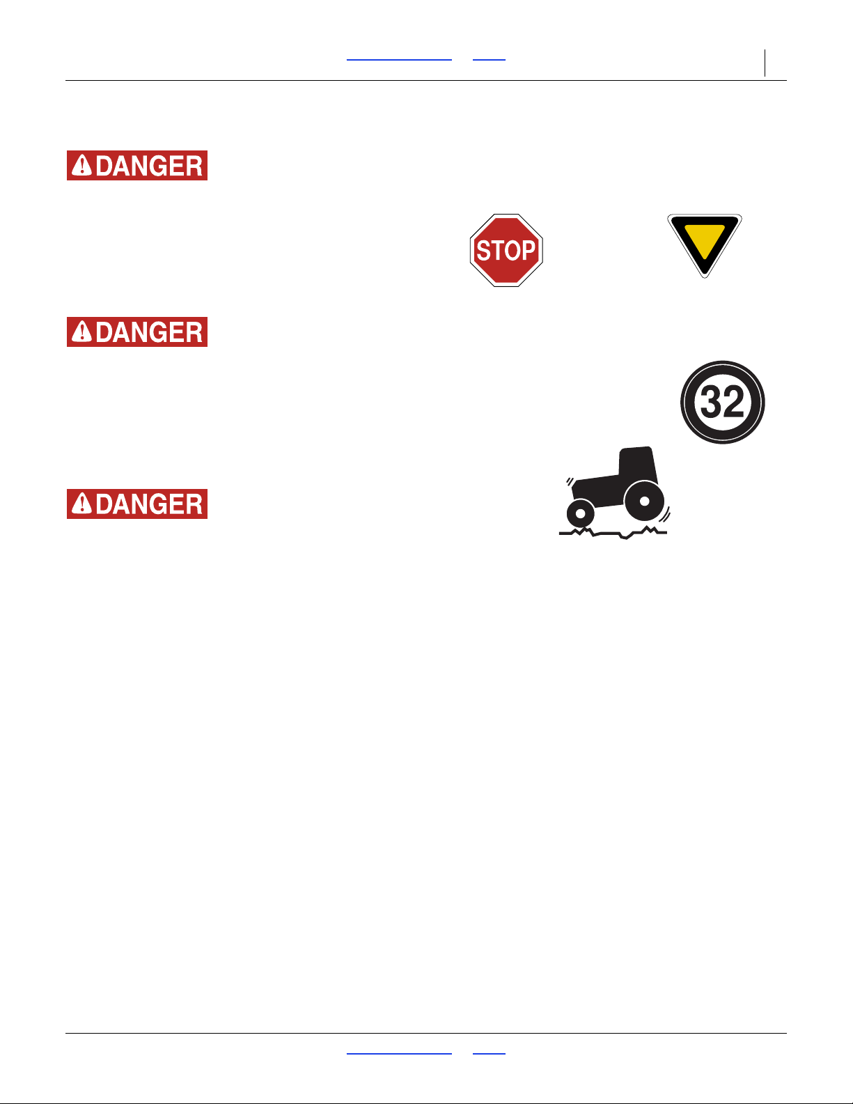
Loss of Control Hazard:
Do not tow the turbo-chisel behind another implement on
public roads. Tow the turbo-chisel to the field with a separate
vehicle. The leading implement may not provide sufficient
lateral control of a trailing implement at highway speeds. The
total weight of the train can also exceed the steering and/or
braking capability of the tractor. The resulting accident could
cause serious injury or death.
Loss of Control Hazard:
Use an adequate towing vehicle. Never tow an implement that
weighs more than 150% of the towing vehicle (transport
vehicle must weigh at least 67% of implement). Ensure that
the towing vehicle is adequate for the task. Using an
inadequate tow vehicle is extremely unsafe, and can result in
loss of control, serious injury and death.
See tables below for harrow transport weights.
Braking and Loss of Control Hazard:
Do not exceed 20 mph (32 kph). Slow down on rough roads.
Transport Steps
Know your implement weight. If tractor capabilities are
marginal, check actual weight of implement at a scale.
32. Check that implement is securely hitched to a
sufficient tractor (page 13).
33. Always use a locking-style hitch pin sized to match
holes in hitch and draw-bar, and rated for the load.
34. Attach safety chain to tractor with enough slack to
permit turning (page 13).
35. Verify correct operation of lights.
36. Install transport locks (page 15).
37. Check that tires are properly inflated (page 28).
38. Plan the route. Avoid steep hills.
39. Always have lights on for highway operation.
40. Do not exceed 32 kph (20 mph). Comply with all
national, regional and local laws when traveling on
public roads.
41. Remember that the implement may be wider than
the towing vehicle. Allow safe clearance.
07/11/2018 Table of Contents Index 566-224M
Page 24

TC5109-5323 Table of Contents Index Operating Instructions 20
Field Operation
This implement is designed to be pulled in the field with
the machine engaged (including wide turns). Lifting for
short distances to clear residue clogs is acceptable.
Lifting for tight turns or reverse moves is required.
Equipment Damage Risk:
Lift for tight turns and reverse moves. Tight turns can result in
a section moving backward. Never back up with harrows on
the ground. If the inside tire stops or rolls backward, the turn is
tight and requires lift.
Field Set-Up Checklists
Use the following tables to develop a final checklist for
your tractor/Turbo-Chisel configuration. Additional or
fewer steps may be necessary depending on tractor
features, Turbo-Chisel options and planting accessories.
Mechanical Checklist (Tractor Hitching) Page
Turbo-Chisel hitched 13
Hitch pin locked
Safety chain secured to tractor or leading
implement
Parking jack stowed 13
Electrical Checklist Page
Verify electrical hookups solid, or connector
securely stowed if not using lights in field.
Hydraulic System Checklist Page
Check tractor hydraulic reservoir full -
Make hydraulic connections 14
Inspect connections for leaks -
Unfold Implement
13
14
General Operation and In-Field Adjustments
1. Remove the transport pins, see “Transport Locks”
on page 15 and unfold machine. Make sure the fold
cylinders are fully extended to allow the wings to fully
flex in the field.
2. If possible have someone observe the machine
during first time operation for levelness, front to rear
and wings to center frame.
07/11/2018 Table of Contents Index 566-224M
Page 25
TC5109-5323 Table of Contents Index Operating Instructions 21
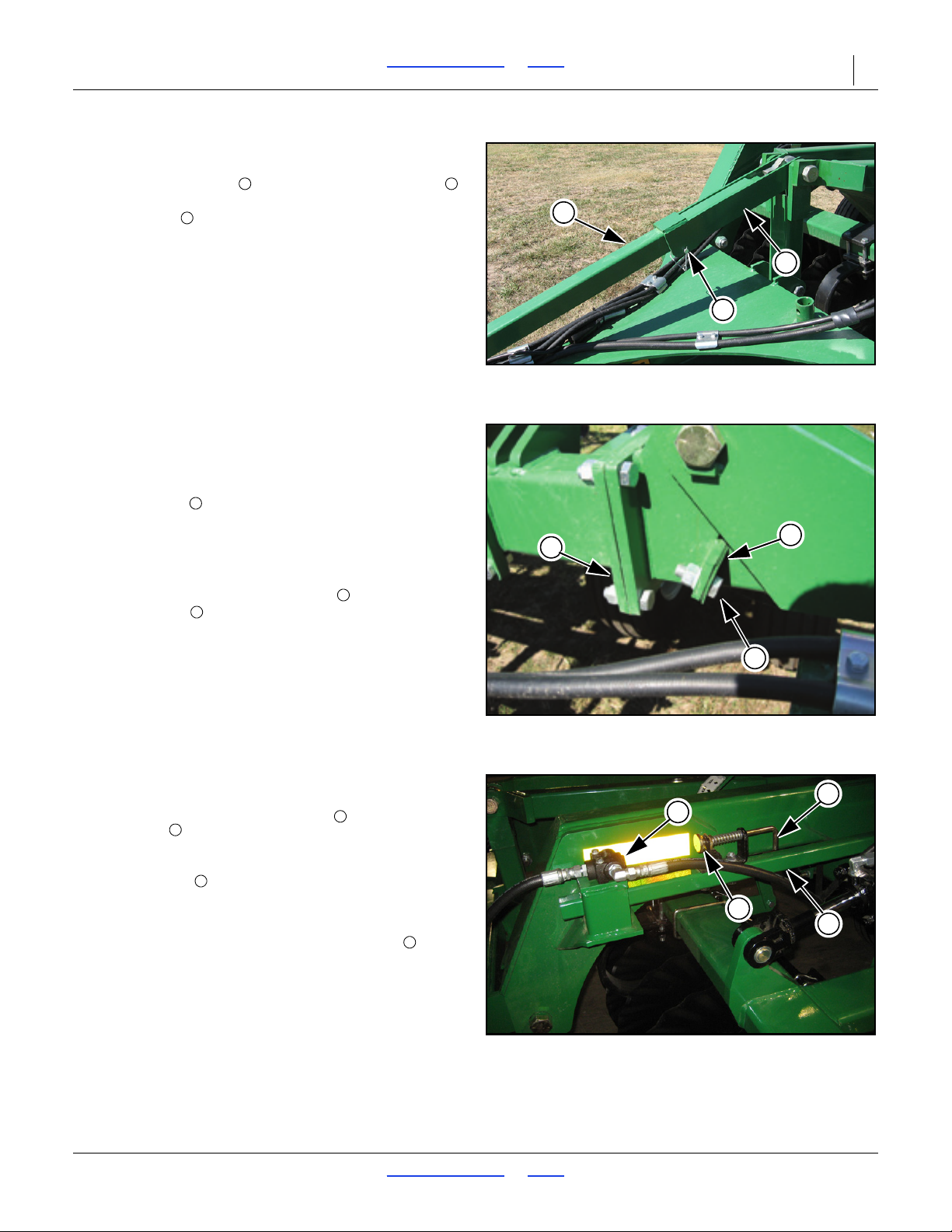
1
2
3
Figure 15
Turnbuckle Adjustment
41987
1
2
3
5
4
4
Figure 16
Wing Adjustment
41774
454
8
7
6
9
Figure 17
Depth Stop Adjustment
41984
678
9
Refer to Figure 15
3. If machine needs leveled from front to rear, remove
the snap wire pin from the turnbuckle lock ,
swing lock off turnbuckle and adjust the hitch
turnbuckle . When done adjusting, be sure and
swing turnbuckle lock back down and secure with
snap wire pin.
Refer to Figure 16
4. If machine is not level when fold cylinders are
completely extended, fold wings back up and instal
shims as needed to level.
Extra shims are stored in manual pak. The extra
shims may be needed in the future if the hinge holes
or bolts begin to wear. There are two different
thickness of shims, you may use multiple shims to
level wings.
5. Remove the two
more shims to raise wings or take shims out to
lower wings.
6. Re-install bolts and tighten to specs, “Tor q ue Value s
Chart” on page 29.
7. For best results, if at all possible, run machine at a
slight angle to the rows. This will improve trash flow
and allow for better dislodging of rootballs and will
help spread the residue more evenly across the field.
3
8 x 114 bolts and either add
Refer to Figure 17
8. When you have machine level and set to the desired
working depth, set the depth stop on the depth
stop tube . This is located at the front of the
machine. This will maintain a constant depth each
time after raising and lowering machine.One full turn
of the handle will change the depth approximately
1
4”.
If after setting the depth stop, the detent on the tractor
kicks out before the stop contacts the button on the
depth stop, slow the hydraulic flow speed down. If this
problem exists, contact the factory service
representative for other possible adjustments. On
tractors with a timed detent setting, set the detent so
when you raise the machine, the pump will run for
to 1 full second after full raise. If it runs longer than
this, damage to the seals of the lift cylinders may
result.
1
2
07/11/2018 Table of Contents Index 566-224M
Page 26
TC5109-5323 Table of Contents Index Operating Instructions 22
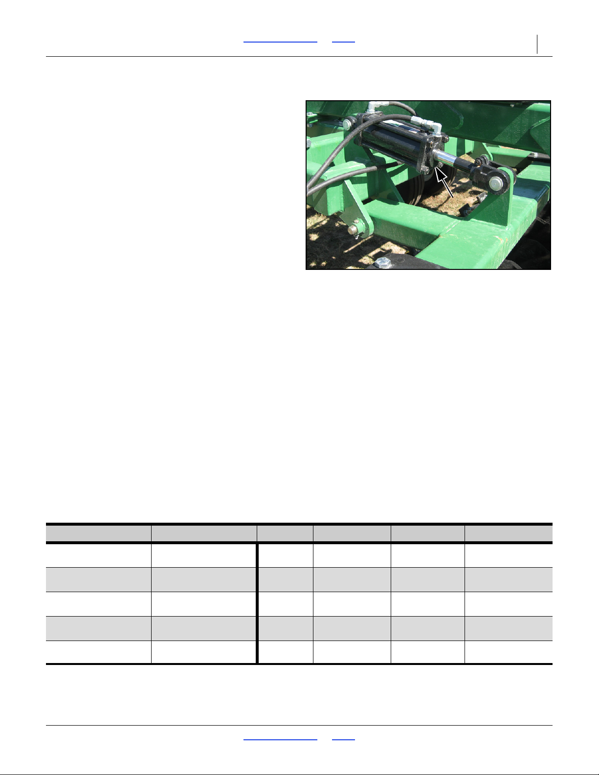
Figure 18
Turbo Coulter Adjustment
41984
Refer to Figure 18
9. Once the machine is set, running level both fore and
aft, from side to side you are ready to run. The first
part of the machine that makes contact with the soil
is the turbo coulters. These can be adjusted hydraulically from the seat of the tractor. These coulters are
designed to cut and size, they will also help with
burying residue as the aggressive turbo blades will
pick up and roll the soil.
These coulters should not be run at a depth deeper
than 5”. Also, in very hard ground, be careful to try not
to force the coulters too deep as it may try to raise the
front of the machine out of the ground as this will
affect the overall performance of the machine.
10. The machine can be equipped with several different
shank options. It is important to understand these
options and how they affect the soil. See a and b for
description.
a. Toggle Trip Shanks with 7” winged point. These can
run up to 11” deep and with winged points, they do
an excellent job of fracturing the soil. These shanks
run 2” deeper than the rear row of shanks.
b. Spring Reset Mounts can be equipped with several
different shank and point configurations. The most
popular is the Parabolic Shank with a 7” winged
point. This point is similar to the ones on the toggle
trip shank except It has a “fin” on it that helps minimize shank “blow out”. The combination of these
shank assemblies and the Toggle Trip shanks provide the best combination for fracturing the ground
completely while leaving the surface in a relatively
“smooth” condition. By following the combination
with a Chopper Reel or Buster Bar, one pass finishing in the Spring is attainable. Spring Reset Mounts
can also be equipped with a Standard Chisel Shank
which supports many point options. See chart below
for a detailed analysis of the varying point options.
Front Row Rear Row Fracture Bury Residue Smoothness Trash Clearance
Toggle Trip 7” Point
Toggle Trip 7” Point
7” Point
Auto Reset/Chisel
w/ 2” Straight Point
Auto Reset/Chisel
w/ 3” or 4” Twisted Point
07/11/2018 Table of Contents Index 566-224M
Auto Reset/ Parabolic
w/ 7” Finned Point
Auto Reset/ Chisel
w/ 7” Winged Point
Auto Reset/ Chisel
w/ 2” Winged Point
Auto Reset/ Chisel
w/ 2” Straight Point
Auto Reset/Chisel
w/ 3” or 4” Twisted Point
Very Good Good Very Good Very Good
Very Good Very Good Good Good
Good Very Good Good Good
Average Good Poor Good
Poor Very Good Very Poor Average
Page 27
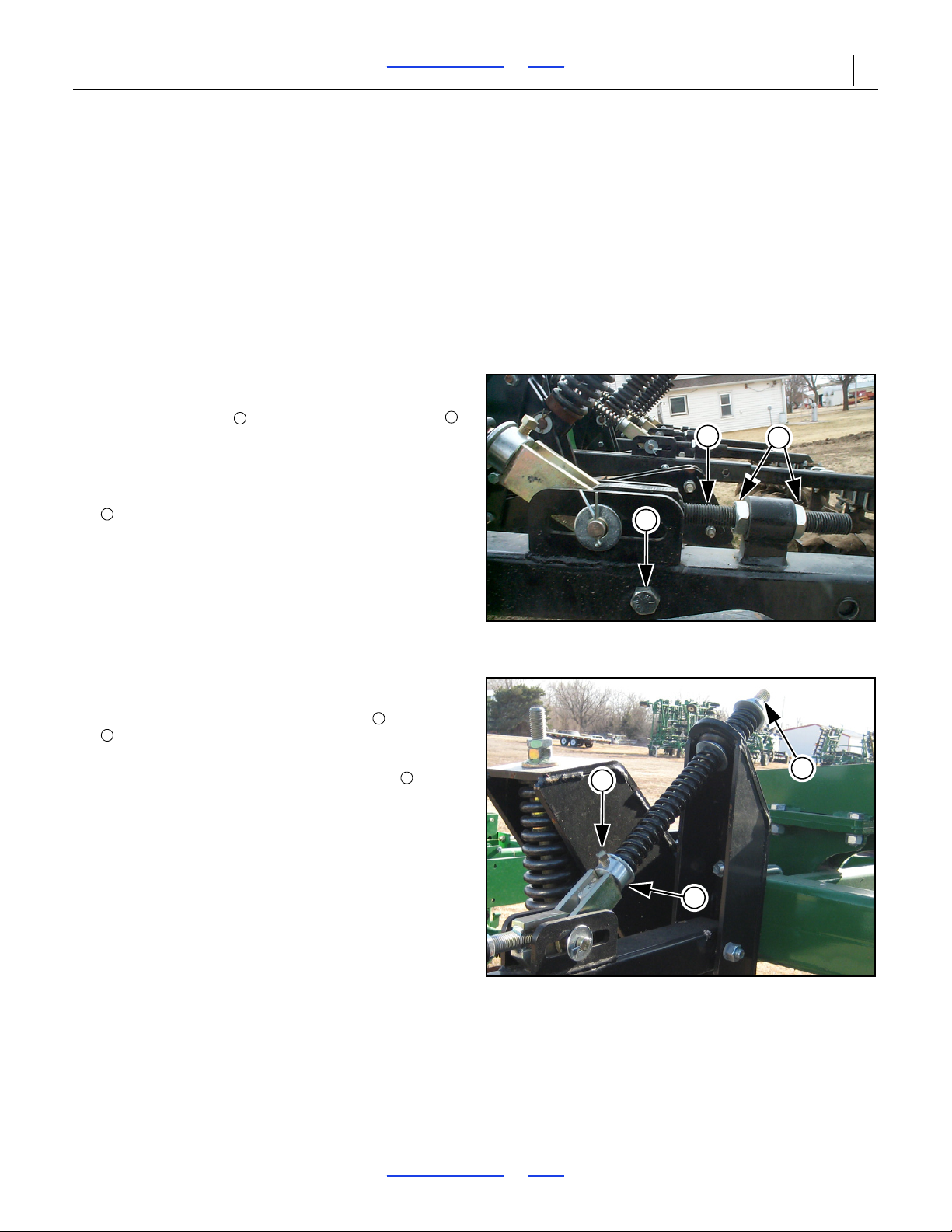
TC5109-5323 Table of Contents Index Operating Instructions 23
2
1
3
Figure 19
Chopper Reel Adjustment
41985
123
6
4
5
Figure 20
Chopper Reel Down Pressure
42005
456
Rear Attachment Settings
Rear Chopper Reel
11. The chopper reel attachment is designed to help size
the soil and residue coming out of the back of the
machine and level the soil surface. The reels should
be run as far forward as possible without causing
plugging of the reel assemblies or the machine. In
wetter conditions, they may need to be moved back
some to allow the soil to “settle” before coming in
contact with the reels. Also in wet conditions, it is not
advisable to apply down pressure on the reels as this
will cause them to plug with mud.
Refer to Figure 19
12. In order to raise or lower the chopper reel assembly,
adjust the eyebolt by loosening the jam nuts .
Extend eyebolt to lower the assembly, retract eyebolt
to raise assembly.
13. Tighten jam nuts securely.
14. To adjust the chopper reels fore and aft, remove bolt
and slide tubes in or out. Adjustment is 3” for each
hole. The bolt may need to move from the back hole
to the front hole or vice verse, depending on the
amount of adjustment needed. Because of weight
concerns, the choppers should run as far forward as
possible while still allowing soil and residue to flow
freely from the rear shanks.
Refer to Figure 20
15. The down pressure can be adjusted two ways. For
slight down pressure, loosen set screw from collar
and slide collar up for more pressure. Tighten set
screw to secure.
16. For added down pressure, tighten lock nut on top
of spring. This will compress the bottom of the
spring, increasing down pressure. This will also raise
the chopper reel so you will also need to re-adjust
eyebolt at the bottom of the spring bolt accordingly.
07/11/2018 Table of Contents Index 566-224M
Page 28
TC5109-5323 Table of Contents Index Operating Instructions 24
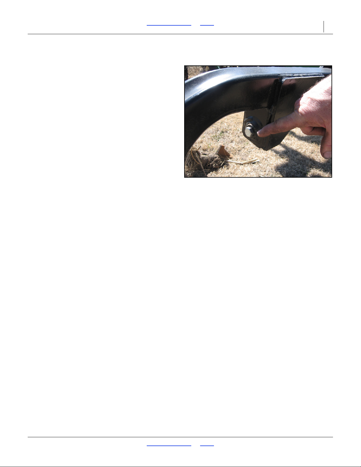
Figure 21
Buster Bar Settings
41989
Buster Bar
Refer to Figure 21
17. The buster bar attachment is designed to knock the
tops of the ridges and to help fill the valleys behind
the chisel shanks. The down pressure can be set by
1
the
2” bolt under the arm. To adjust the pressure,
loosen the jam nut on the back side and then adjust
1
the
2” bolt. To increase down pressure, loosen the
bolt. In some instances, especially when you are
running the chisel very deep, the bolt head will not
be in contact with the ball joint when the unit is out of
the ground. Once the unit is lowered into the ground,
the bolt head will come in contact with the ball joint
and pressure will be applied. Once the proper
tension is set, re-tighten the jam nut. There are no
other adjustments to this attachment.
07/11/2018 Table of Contents Index 566-224M
Page 29
TC5109-5323 Table of Contents Index Maintenance and Lubrication 25
50
Multipurpose
spray lube
Multipurpose
grease lube
Multipurpose
oil lube
Intervals (service hours)
at which lubrication is
required
41991
Maintenance and Lubrication
Maintenance
1. Always use the transport lock when working on or
doing maintenance to the Turbo-Chisel. If folded, be
sure your wing stop pins are in place. Read and
understand all safety decals on your equipment.
2. During the first season of operation, and periodically
after that, check your bolts for tightness. Check
shank pivot bolts for tightness. Check shank pivot
bolts on the spring-loaded shank, these must remain
tight to prevent excessive wear on the shank
assembly.
3. Replace or rotate worn parts as needed -- hinge
bolts, clevis pins, bearings, sweeps, shanks, etc.
4. Check and tighten or replace any hydraulic leaks.
Check hoses for any leaks. It is important that there
are no leaks on the equipment.
5. Grease wheel bearings and walking beams
sparingly. Over greasing may cause damage to
seals and reduce the life of the bearing. Grease
hinge points periodically.
6. Check drag bolts for loosness or excessive wear.
Replace broken or bent teeth. Your drag is an
important part of the tillage operation.
Lubrication
7. If machine is stored outdoors over the winter
months, it is a good idea to fold the machine then set
it down on the ground so all the cylinders are
retracted to protect the cylinder rods. This will extend
the life of the cylinder seals and reduce internal and
external leaks.
By following and maintaining a routine service and
lubrication program, your tillage equipment will give you
many years of service.
For the most current manual information, visit Great
Plains website listed below. For more information on
operating, adjusting or maintaining your Great
Plains Discovator, assistance is available. Contact:
Great Plains Service Department
1525 E. North St.
PO Box 5060
Salina, KS 67402-5060
Or go to www.greatplainsag.com and follow the contact
information at the bottom of your screen for our service
department.
(800)255-9215
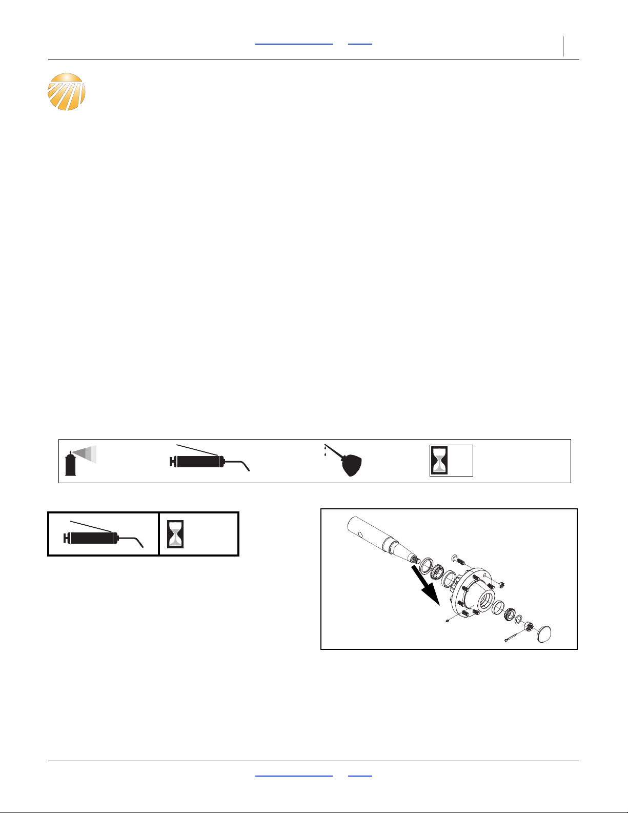
Wheel Bearing Hub
50
1 zerk on each hub;
4 total
Units made after 3/2014 will not have a grease zerk.
Type of Lubrication: Grease
Quantity: Sparingly, Do Not Over Grease, may cause
damage to seal.
Repack wheel bearings annually or every 2500 acres.
07/11/2018 Table of Contents Index 566-224M
Page 30
TC5109-5323 Table of Contents Index Maintenance and Lubrication 26
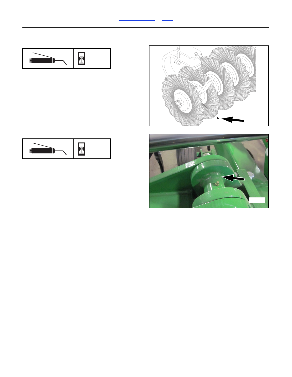
41992
42674
Coulter Bearings
50
One on rear of each c-flex bearing.
Units made after 3/2014 will not have a grease zerk.
Type of Lubrication: Grease
Quantity: Grease every 50 hours, 2 to 3 pumps. In heavy
conditions grease every 20 hours, 2 to 3 pumps.
Wing Hinge
10
One on each wing hinge (3-Section)
Type of Lubrication: Grease
Quantity: Sparingly or 2 pumps
07/11/2018 Table of Contents Index 566-224M
Page 31

TC5109-5323 Table of Contents Index Appendix 27
Model No. TC5109 TC5111 TC5113 TC5115
Tillage Width 11' 3" (3.43 m) 13' 9" (4.20 m) 16' 3" (4.95 m) 18' 9" (5.72 m)
Center Section 10' (3.05 m) 10' (3.05 m) 10' (3.05 m) 10' (3.05 m)
Wing N/A 3' 6" (1.07) 4' 9" (1.45)
Number of Shanks 9111315
Shank Spacing
19 23 27 31
Blade Spacing
Weight (base machine) 8,080 lbs. (3665 kg) 9,835 lbs. (4461 kg) 11,240 lbs. (5098 kg) 12,600 lbs. (5715 kg)
Transport Width 11' 6" (3.50 m) 14' 3" (4.4 m) 16' 6" (5 m) 19' (5.80 m)
Transport Height N/A N/A N/A N/A
Length (w/o attachment) 22' 10" (6.95 m) 22' 10" (6.95 m) 22' 10" (6.95 m) 22' 10" (6.95 m)
Tire Size Center 12.5L x 15" 12-ply 12.5L x 15" 12-ply 12.5L x 15" F-ply 12.5L x 15" F-ply
Tire Size Wing N/A N/A N/A N/A
Horsepower (PTO) Chisel Shanks* 200-250 230-285 270-329 315-385
Kilowatt Chisel Shanks 150-185 170-210 200-245 235-290
Horsepower (PTO) Parabolic Shanks** 230-260 255-315 315-385 355-440
Kilowatt Parabolic Shanks 170-190 190-235 235-290 260-330
Model No. TC5313 TC5315 TC5317 TC5319 TC5321 TC5323
Tillage Width 16' 3" (4.95 m) 18' 9" (5.72 m) 21' 3" (6.48 m) 23' 9" (7.24 m) 26' 3" (8.00 m) 28' 9" (8.76 m)
Center Section 10' (3.05 m) 10' (3.05 m) 10' (3.05 m) 10' (3.05 m) 10' (3.05 m) 10' (3.05 m)
Wing 3' 6" (1.07) 4' 9" (1.45) 6' (1.83 m) 7' 3" (2.21 m) 8' 9" (2.67 m) 9' 6" (2.90 m)
Number of Shanks 13 15 17 19 21 23
Shank Spacing
27 31 35 39 43 47
Blade Spacing
Weight (base machine) 11,280 lbs. (5117 kg) 12,900 lbs. (5851 kg) 13,700 lbs. (6214 kg) 14,200 lbs. (6441 kg) 15,650 lbs. (7099 kg) 16,250 lbs. (7371 kg)
Transport Width 14' 6" (4.42 m) 14' 6" (4.42 m) 14' 9" (4.50 m) 14' 9" (4.50 m) 14' 9" (4.50 m) 14' 9" (4.50 m)
Transport Height 9' 6" (2.90 m) 10' 3" (3.12 m) 11' (3.35 m) 12' 3" (3.73 m) 13' 6" (4.11 m) 14' 6" (4.42 m)
Length (w/o attachment) 22' 10" (6.95 m) 22' 10" (6.95 m) 22' 10" (6.95 m) 22' 10" (6.95 m) 22' 10" (6.95 m) 22' 10" (6.95 m)
Tire Size Center 12.5L x 15" F-ply 12.5L x 15" F-ply 12.5L x 15" F-ply 12.5L x 15" F-ply 12.5L x 15" F-ply 12.5L x 15" F-ply
Tire Size Wing N/A N/A 12.5L x 15" 12-ply 12.5L x 15" 12-ply 12.5L x 15" 12-ply 12.5L x 15" 12-ply
Horsepower (PTO) Chisel Shanks* 270-329 315-385 355-440 397-468 440-510 497+
Kilowatt Chisel Shanks 200-245 235-290 260-330 295-350 325-380 370+
Horsepower (PTO) Parabolic Shanks** 315-385 355-440 425-500 450-530 568+ N/A
Kilowatt Parabolic Shanks 235-290 260-330 320-370 335-395 425+ N/A
2' 6" (.076 m)
15" (.38 m) 15" (.38 m) 15" (.38 m) 15" (.38 m)
Number of Coulters
7.5" (.19 m) 7.5" (.19 m) 7.5" (.19 m) 7.5" (.19 m)
15" (.38 m) 15" (.38 m) 15" (.38 m) 15" (.38 m) 15" (.38 m) 15" (.38 m)
Number of Coulters
7.5" (.19 m) 7.5" (.19 m) 7.5" (.19 m) 7.5" (.19 m) 7.5" (.19 m) 7.5" (.19 m)
Appendix
TC Specifications and Capacities
* Available with 2” straight or 3” twisted points on chisel shanks
** Equipped with 7” winged points on parabolic shanks
With a continued commitment to constantly improving our products, these specifications are subject to change without
notice.
07/11/2018 Table of Contents Index 566-224M
Page 32
TC5109-5323 Table of Contents Index Appendix 28
2
5
4
9
8
7
5
3
Figure 22
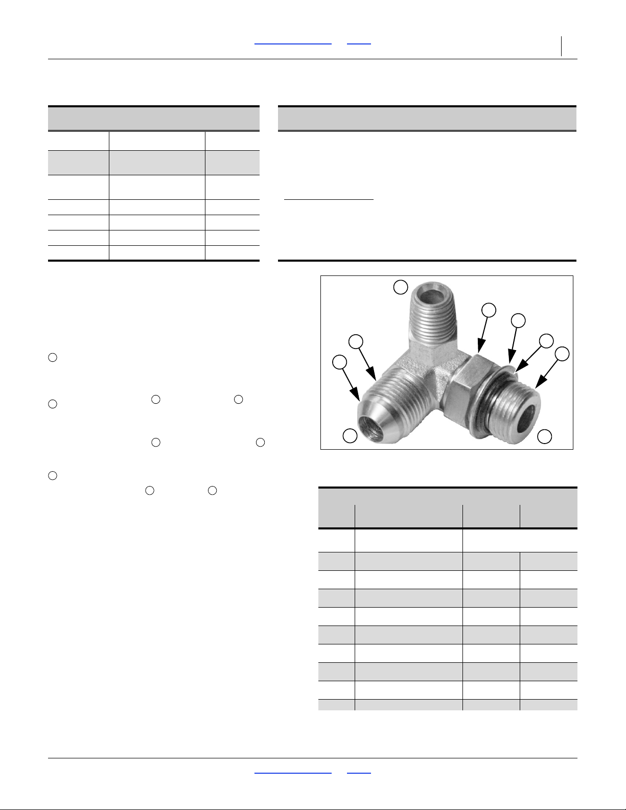
Hydraulic Connector ID
31282
Fittings Torque Values
Dash
Size
Fitting N-m Ft-Lbs
-4
1
4-18 NPT
1.5-3.0 turns past finger
tight
-5
1
2-20 JIC
19-20 14-15
-5
1
2-20 ORB w/jam nut
12-16 9-12
-5
1
2 -20 ORB straight
19-26 14-19
-6
5
16-18 JIC
24-27 18-20
-6
5
16-18 ORB w/jam nut
16-22 12-16
-6
5
16-18 ORB straight
24-33 18-24
-8
3
4 -16 JIC
37-53 27-39
-8
3
4 -16 ORB w/jam nut
27-41 20-30
3
37-58 27-43
1
124535789
Tire Inflation Chart
Tire Inflation Chart
Wheel Tire Size Inflation
Transport 12.5L x 15” F-Ply
Transport/
Wings
12.5L x 15” 12-Ply
620 kPa
90 psi
379 kPa
55 psi
Hydraulic Connectors and Torque
Refer to Figure 22 (a hypothetical fitting)
Leave any protective caps in place until immediately
prior to making a connection.
NPT - National Pipe Thread
Note tapered threads, no cone/flare, and no O-ring.
Apply liquid pipe sealant for hydraulic applications.
Do not use tape sealant, which can clog a filter and/or plug
an orifice.
JIC - Joint Industry Conference (SAE J514)
Note straight threads and the 37 cone on “M” fittings
(or 37 flare on “F” fittings).
Use no sealants (tape or liquid) on JIC fittings.
ORB - O-Ring Boss (SAE J514)
Note straight threads and elastomer O-Ring .
Prior to installation, to prevent abrasion during tightening,
lubricate O-Ring with clean hydraulic fluid.
Use no sealants (tape or liquid) on ORB fittings.
ORB fittings that need orientation, such as the ell depicted,
also have a washer and jam nut (“adjustable thread
port stud”). Back jam nut away from washer. Thread fitting
into receptacle until O-Ring contacts seat. Unscrew fitting to
desired orientation. Tighten jam nut to torque specification.
Tire Warranty Information
All tires are warranted by the original manufacturer of the tire. Tire
warranty information is found in the brochures included with your
Operator’s and Parts Manuals or online at the manufacturer’s web sites
listed below. For assistance or information, contact your nearest
Authorized Farm Tire Retailer.
Manufacturer
Firestone www.firestoneag.com
Gleason www.gleasonwheel.com
Titan www.titan-intl.com
Galaxy www.atgtire.com
BKT www.bkt-tire.com
Web site
07/11/2018 Table of Contents Index 566-224M
Page 33
TC5109-5323 Table of Contents Index Appendix 29
946
25199m
Bolt
Size
Bolt Head Identification
Bolt
Size
Bolt Head Identification
Grade 2 Grade 5 Grade 8 Class 5.8 Class 8.8 Class 10.9
in-tpi
a
N-m
b
N-m N-m
mm x pitch
c
N-m N-m N-m
1
⁄4-20
7.4 11 16
M 5 X 0.8
1
⁄4-28
8.5 13 18
M 6 X 1
71115
5
⁄16-18
15 24 33
M 8 X 1.25
17 26 36
5
⁄16-24
17 26 37
M 8 X 1
18 28 39
3
⁄8-16
27 42 59
M10 X 1.5
33 52 72
3
⁄8-24
31 47 67
M10 X 0.75
39 61 85
7
⁄16-14
43 67 95
M12 X 1.75
58 91 125
7
⁄16-20
49 75 105
M12 X 1.5
60 95 130
1
⁄2-13
66 105 145
M12 X 1
90 105 145
1
⁄2-20
75 115 165
M14 X 2
92 145 200
9
⁄16-12
95 150 210
M14 X 1.5
99 155 215
9
⁄16-18
105 165 235
M16 X 2
145 225 315
5
⁄8-11
130 205 285
M16 X 1.5
155 240 335
5
⁄8-18
150 230 325
M18 X 2.5
195 310 405
3
⁄4-10
235 360 510
M18 X 1.5
220 350 485
3
⁄4-16
260 405 570
M20 X 2.5
280 440 610
7
⁄8-9
225 585 820
M20 X 1.5
310 650 900
7
⁄8-14
250 640 905
M24 X 3
480 760 1050
1-8
340 875 1230
M24 X 2
525 830 1150
1-12
370 955 1350
M30 X 3.5
960 1510 2100
1
1
⁄8-7
480 1080 1750
M30 X 2
1060 1680 2320
1
1
⁄8-12
540 1210 1960
M36 X 3.5
1730 2650 3660
1
1
⁄4-7
680 1520 2460
M36 X 2
1880 2960 4100
1
1
⁄4-12
750 1680 2730
1
3
⁄8-6
890 1990 3230
a. in-tpi = nominal thread diameter in inches-threads per inch
1
3
⁄8-12
1010 2270 3680
b. N· m = newton-meters
1
1
⁄2-6
1180 2640 4290
1
1
⁄2-12
1330 2970 4820
c. mm x pitch = nominal thread diameter in mm x thread pitch
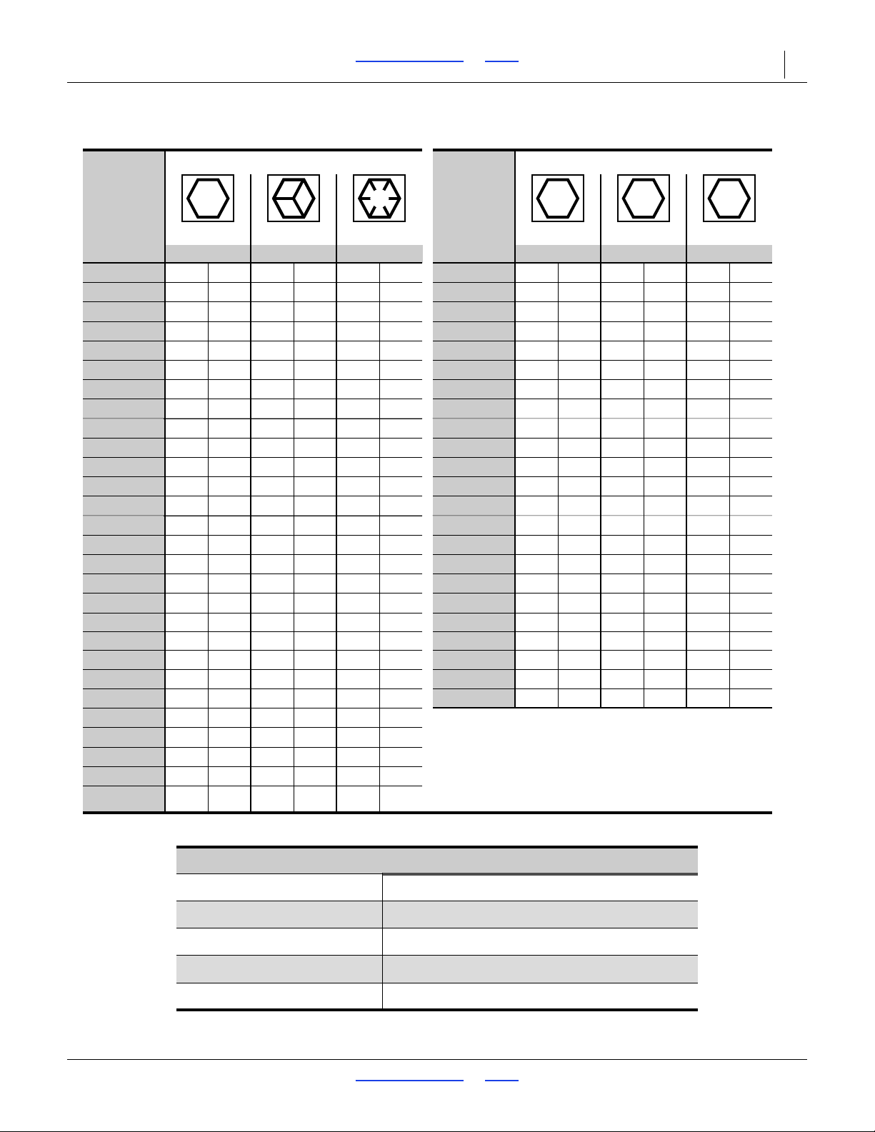
Torque tolerance + 0%, -15% of torquing values. Unless otherwise specified use torque values listed above.
5.8 8.8 10.9
25199
ft-lb
d
ft-lb ft-lb ft-lb ft-lb ft-lb
5.6 8 12
61014 5 811
11 17 25 12 19 27
13 19 27 13 21 29
20 31 44 24 39 53
22 35 49 29 45 62
32 49 70 42 67 93
36 55 78 44 70 97
49 76 105 66 77 105
55 85 120 68 105 150
70 110 155 73 115 160
79 120 170 105 165 230
97 150 210 115 180 245
110 170 240 145 230 300
170 265 375 165 260 355
190 295 420 205 325 450
165 430 605 230 480 665
185 475 670 355 560 780
250 645 910 390 610 845
275 705 995 705 1120 1550
355 795 1290 785 1240 1710
395 890 1440 1270 1950 2700
500 1120 1820 1380 2190 3220
555 1240 2010
655 1470 2380
745 1670 2710
870 1950 3160
d. ft-lb = foot pounds
980 2190 3560
357
Torque Values Chart
07/11/2018 Table of Contents Index 566-224M
Wheel Bolt Torque Values
Wheel Bolt Torque Values
Wheel Bolt Torque Values
Chopper Hub Spindle Values
Gang Bolt Torque
Torque Values Chart
3
1
4”-1288 N-m (850ft-lb (165lbs on 5’ cheater))
1
2”-20 (75-85ft-lbs)
5
16”-18 (80-90ft-lbs)
5
8”-18 (85-100ft-lbs)
7
8”-9 350 ft-lbs
Page 34

TC5109-5323 Table of Contents Index Appendix 30
Warranty
Great Plains Manufacturing, Incorporated warrants to the original purchaser that this tillage
equipment will be free from defects in material
and workmanship for a period of one year from the date of original purchase when used as intended and under normal service and conditions
for personal use; 90 days for commercial or rental purposes. This Warranty is limited to the replacement of any defective part by Great Plains
Manufacturing, Incorporated and the installation by the dealer of any
such replacement part. Great Plains reserves the right to inspect any
equipment or part which are claimed to have been defective in material
or workmanship.
This Warranty does not apply to any part or product which in Great
Plains’ judgement shall have been misused or damaged by accident or
lack of normal maintenance or care, or which has been repaired or altered in a way which adversely affects its performance or reliability, or
which has been used for a purpose for which the product is not designed. This Warranty shall not apply if the product is towed at a speed
in excess of 20 miles per hour.
Claims under this Warranty must be made to the dealer which originally
sold the product and all warranty adjustments must by made through
such dealer. Great Plains reserves the right to make changes in materials or design of the product at any time without notice.
This Warranty shall not be interpreted to render Great Plains liable for
damages of any kind, direct, consequential, or contingent, to property.
Furthermore, Great Plains shall not be liable for damages resulting from
any cause beyond its reasonable control. This Warranty does not extend to loss of crops, losses caused by harvest delays or any expense
or loss for labor, supplies, rental machinery or for any other reason.
No other warranty of any kind whatsoever, express or implied, is
made with respect to this sale; and all implied warranties of merchantability and fitness for a particular purpose which exceed
the obligations set forth in this written warranty are hereby disclaimed and excluded from this sale.
This Warranty is not valid unless registered with Great Plains Manufacturing, Incorporated within 10 days from the date of original purchase.
42134
07/11/2018 Table of Contents Index 566-224M
Page 35

TC5109-5323 Cover Table of Contents Index 31
Index
A
address, Great Plains ..................11,25
amber reflectors ...................................5
B
bearings ..............................................25
bolts ....................................................25
C
Category III .........................................13
Category IV ........................................13
Caution
Read Operator’s Manual ...............6
CAUTION, defined ...............................1
chain ...................................................13
checklists
electrical ......................................20
field ..............................................20
hydraulic system .........................20
mechanical
implement ............................20
pre-setup .....................................12
pre-start .......................................18
children .................................................2
color code, hose .................................14
,
contact Great Plains ....................11
coulter bearings ..................................26
covered models ..................................10
customer service ................................11
cylinder symbols .................................14
25
D
Danger
Crushing Hazard ...........................7
DANGER, defined ................................1
decal replacement ................................5
decals
caution
read manual ...........................6
danger
crushing .................................7
cutting of foot .........................9
electrocution...........................7
notice
transport lock .........................8
speed
30km per hr ............................9
warning
hand crushing ........................8
high pressure fluid ..................8
overhead wing ........................7
tongue rising ..........................9
decal, safety .........................................5
definitions ...........................................10
depth stop adjustment ........................21
directions ............................................10
drag bolts ........................................... 25
E
email, Great Plains.......................11,25
F
fire ........................................................ 1
H
handles, hose..................................... 14
high pressure fluid .............................. 14
high pressure fluids .............................. 2
,
hills ...............................................13
hitch pin.............................................. 19
hitch turnbuckle adjustment ............... 15
hitching............................................... 13
hose handles ...................................... 14
hoses, hydraulic ................................. 14
hydraulic connectors .......................... 28
hydraulic hoses .................................. 14
hydraulic safety .................................... 2
19
I
inflation............................................... 28
J
jack..................................................... 13
JIC...................................................... 28
Joint Industry Conference .................. 28
J514 ................................................... 28
K
kPa ..................................................... 28
L
leaks...............................................2,25
left-hand, defined ............................... 10
lights...............................................2,14
lubrication........................................... 25
M
Maintenance ...................................... 25
maintenance safety .............................. 4
,14,
medical assistance..................2
model number .................................... 11
18
N
National Pipe Thread ......................... 28
negative tongue weight ...................... 13
Note, defined...................................... 10
Notice, defined ................................... 10
NPT .................................................... 28
O
orange reflector .................................... 6
ORB ................................................... 28
orientation rose .................................. 10
O-Ring Boss....................................... 28
outside wing hinge ............................. 26
owner assistance ............................... 11
P
parts....................................................25
phone number, GP .............................12
pin, hitch .............................................19
psi .......................................................28
R
red reflectors.........................................6
reflectors
amber ............................................5
orange ...........................................6
red .................................................6
SMV...............................................5
reflectors, safety ...................................5
repair parts .........................................11
reverse................................................20
riders.....................................................2
right-hand, defined..............................10
rose, oriention .....................................10
S
SAE J514............................................28
safety chain ...................................2,13
safety decal ..........................................5
safety information .................................1
safety symbol........................................1
scale ...................................................19
serial number ......................................11
setup ...................................................12
shutdown ..............................................3
slopes .................................................13
SMV (Slow Moving Vehicle) .................5
Spanish............................................ 6
Specifications and Capacities.............27
speed ....................................................7
speed limit
forward ........................................19
transport ......................................19
storage..................................................3
storing machine ..................................25
support......................................... 11
symbol, safety.......................................1
,
,
25
T
tables
document family ..........................10
fittings torque ...............................28
hose color code ...........................14
models covered ...........................10
torque values ...............................29
tire inflation .........................................28
tires .......................................................3
towing .................................................19
towing vehicle capability .....................19
transport .............................................19
transport lock ......................................25
7
07/11/2018 Cover Table of Contents 566-224M
Page 36

TC5109-5323 Cover Table of Contents Index 32
transport locks ....................................15
transport locks storage .......................15
transport speed ....................................3
transporting ........................................18
turbo coulter adjustment .....................22
turnbuckle adjustment ........................21
U
URLs, tires ..........................................28
W
WARNING, defined ..............................1
warranty ..............................................28
weight .................................................19
weight, implement ..............................19
welding .................................................4
Wheel Bearing Hub ............................25
wing adjustment .................................21
Wing Depth Adjustment......................16
www ....................................................28
Numerics
13 mph .................................................3
,
20 mph .......................................... 3
22 kph ...................................................3
32 kph ...................................................3
566-224M, manual ............................. 10
566-224P, manual ..............................10
566-224Q-ENG, manual .....................10
566-224Q, manual ..............................10
818-055C, reflector ...............................5
838-094C, decal ...................................8
838-598C, decal ...................................6
838-599C, decal ...................................7
838-600C, decal ...................................7
838-602C, decal ...................................7
838-603C, reflector ...............................6
838-606C, decal ...................................9
838-611C, decal ...................................8
838-613C, decal ...................................8
838-614C, reflector ...............................6
838-615C, reflector ...............................5
848-271C, decal ...................................9
19
07/11/2018 Cover Table of Contents 566-224M
Page 37

Table of Contents Index
Table of Contents Index
Page 38

Great Plains, Mfg.
1525 E. North St.
P.O. Box 5060
Salina, KS 67402
 Loading...