

Page 1
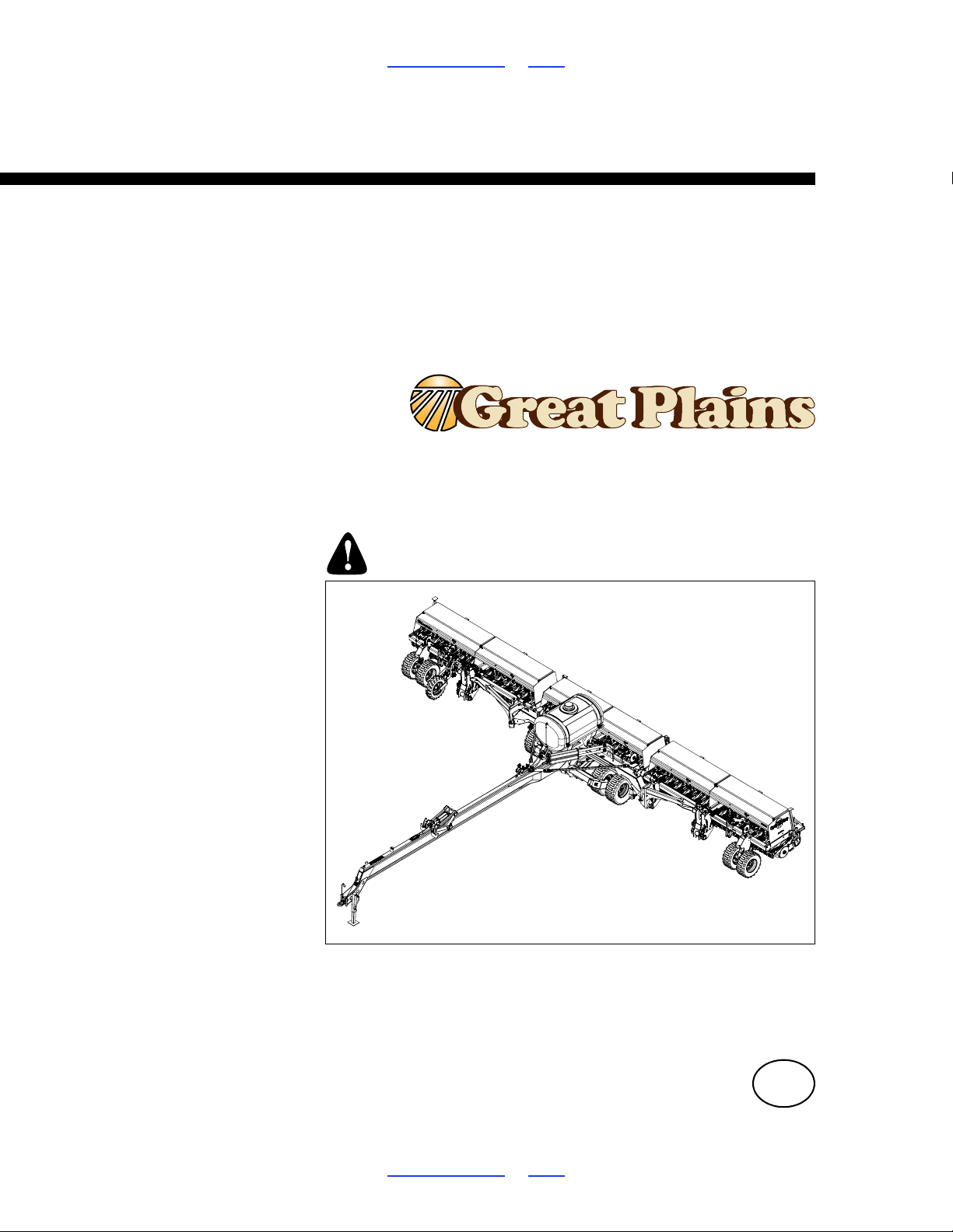
Table of Contents Index
36268
Operator Manual
3-Section 50 Foot Folding Drill
3S-5000/F/HD/HDF
Manufacturing, Inc.
www.greatplainsmfg.com
Read the operator manual entirely. When you see this symbol, the
subsequent instructions and warnings are serious - follow without
exception. Your life and the lives of others depend on it!
Illustrations may show optional equipment not supplied with standard unit or
may depict similar 2S, 3S-3000, 3S-4000 and HD drills where a topic is
identical.
ORIGINAL INSTRUCTIONS
© Copyright 2017 Printed 2017-10-26 195-325M
Table of Contents Index
EN
Page 2
3S-5000/F/HD/HDF Table of Contents Index ii
Dealer QRC
The QR Code (Quick Response) to the
left will take you to available dealers for
Great Plains products. Refer to the
Parts Manual QR Locater for detailed
instructions.
Manual Family QRC
The QR Code (Quick Response) to the
left will take you to this machine’s family
of manuals. Use your smart phone or
tablet to scan the QR Code with an
appropriate App to begin viewing.
Machine Identification
Record your machine details in the log below. If you replace this manual, be sure to transfer this information
to the new manual.
If you, or the dealer, have added Options not originally ordered with the machine, or removed Options that
were originally ordered, the weights and measurements are no longer accurate for your machine. Update
the record by adding the machine weight and measurements on page 96 with the Option(s) weight and
measurements.
Model Number
Serial Number
Machine Height
Machine Length
Machine Width
Machine Weight
Year of Construction
Delivery Date
First Operation
Accessories
Dealer Contact Information
Name:
Street:
City/State:
Telephone:
Email:
Dealer’s Customer
No.:
2017-10-26 Table of Contents Index 195-325M
Page 3

3S-5000/F/HD/HDF Cover Index Table of Contents iii
Table of Contents
Important Safety Information.................................................1
Safety Decals ....................................................................6
Introduction...........................................................................14
Description of Unit...........................................................14
Intended Usage...................................................... ..14
Models Covered ..............................................................14
Document Family .....................................................14
Using This Manual...................................... .....................15
Definitions.................................................................15
Owner Assistance............................................................16
Further Assistance...................................... .....................16
Preparation and Setup .........................................................17
Post-Delivery/Seasonal Setup.........................................17
Pre-Planting Setup ..........................................................17
Leveling the Drill............................................................ ..18
Center Box Frame Leveling......................................18
Opener Frames........................................................18
Wing Box Alignment.................................................19
Tool Bar Height ........................................................19
Align Transfer Drive Shaft........................................20
Hitching Tractor to Drill....................................................22
Adjusting the Drill Hitch ...........................................22
Hydraulic Hose Hookup ...................................................25
Operating Instructions.........................................................26
Pre-Start Checklist...........................................................26
Folding.............................................................................27
Unfolding .........................................................................29
Folding and Unfolding Quick Reference..........................31
Setting the Bypass Valve.................................................31
Opener Operation............................................................33
Active Hydraulic Systems.........................................34
Priority Flow Hydraulic Systems...............................35
Non-Active Hydraulic System...................................35
Opener Depth...........................................................36
Raising and Lowering Openers .......................................36
Opener Lock Up .............................................................37
Loading Materials................ ... ... .................................... ..38
Fertilizer Box Operation...................................................40
Using Fertilizer Compartment...................................40
Seeding with Both Compartments............................40
Liquid Fertilizer System (Option).....................................42
Liquid Fertilizer System Elements............................43
Loading Liquid Fertilizer................ ... ........................44
Transporting the Drill................. ... ...................................46
Transport Checklist ........................................ ... ... ....46
Point Row Operation (Option)..................................47
Shaft Monitor Operation (Option).............................47
Acremeter Operation.......................................................48
Parking............................................................................49
Parking with Drill Unfolded.......................................49
Parking with Drill Folded ........................................ ..49
Storage ............................................................................50
Adjustments..........................................................................51
Main Box Seed Rate Handle...........................................52
Position Seed Cup Doors................................................52
Frame Adjustments.........................................................53
Tool Bar Height Adjustment.....................................53
Opener Frame Adjustment.......... ....................................54
Opener Frame Clearance ........................................55
Frame Level ................................ ... .................................56
Hydraulic Down Pressure All Openers............................57
00 Row Unit Adjustm
ents................................................59
00HD Row Unit Adjustments...........................................60
Opener Height.................................................................61
Row Unit Down Pressure (Spring) ..................................61
Disc Blade Adjustments ..................................................62
Adjusting Disc Contact.............................................62
Dry Fertilizer Tube Adjustment........................................63
Liquid Fertilizer Adjustments (Option).............................64
00 Series Disk Scraper Adjustment.................................67
Seed Firmer Adjustments........................................ ... ... ..67
Keeton
®
Seed Firmer Adjustment............................67
00 Series Seed-Lok® Lock Up......................... ........68
00 & 00HD Series Opener Depth....................................68
Press Wheel Adjustment..........................................68
Troubleshooting...................................................................69
Maintenance and Lubrication..............................................72
Maintenance....................................................................72
Bleeding Hydraulics............................................ ... .. ... .....73
Bleeding Opener Lift Hydraulics...............................74
Bleeding Fold Hydraulics .........................................75
Bleeding Transport Lift Hydraulics...........................76
Opener Hydraulic Filters ..........................................77
Drive System Maintenance .............................................78
Seed Flap Replacement..................................... ... .. ........79
Marker Maintenance........................................................79
Materials Clean-Out ........................................................80
Main Box Clean-Out.................................................80
Fertilizer Box Clean-Out...........................................80
Small Seeds Box Clean-Out ....................................80
© Copyright 2001, 2002, 2003, 2006, 2007, 2009, 2010, 2012, 2013, 2014, 2015, 2016, 2017 All rights Reserved
Great Plains Manufacturing, Inc. provides this publication “as is” without warranty of any kind, either expressed or implied. While every precaution has be en
taken in the preparation of this manual, Great Plains Manufacturing, Inc. assumes no responsibility for errors or omissions. Neither is any liability assumed
for damages resulting from the use of the information contained herein. Great Plains Manufacturing, Inc. reserves the right to revise and improve its products
as it sees fit. This publication describes the state of this product at the time of its publication, and may not reflect the product in the future.
Registered Trademarks of Great Plains Man ufa cturi ng, Inc. i ncl ude: Air-Pro, Clear-Shot, Discovator, Great Plains, Land Pri de, M eterCone,
Nutri-Pro, Seed-Lok, Solid Stand, Terra-Guard, Turbo-Chisel, Turbo-Chopper , Turbo-Max, Turbo-Till, Ultra-Till, Whirlfilter, and Yield-Pro.
Trademarks of Great Plains Manufactu ring, In c. include : AccuShot, Max-Chisel, Row-Pro,
Singulator Plus, Short Disk, Swath Command, Terra-Tine, Ultra-Chisel, and X-Press.
Brand and Product Names that appear and ar e owne d by o thers are t rademar ks of th eir r especti ve owner s.
Printed in the United States of America
2017-10-26 Cover Index 195-325M
Page 4

3S-5000/F/HD/HDF Cover Index Table of Contents iv
Liquid Fertilizer Clean-Out........................................81
Chain Maintenance..........................................................82
Chain Slack..............................................................82
Lubrication.......................................................................83
Options..................................................................................90
Appendix A - Reference Information ..................................96
Specifications and Capacities..........................................96
Tire Inflation Chart...........................................................96
Dimensions (Transport) 3S-5000/F/HD/HDF ..................97
Hydraulic Diagrams.........................................................98
Torque Values Chart.....................................................109
Appendix B - Option Installation.......................................110
Carbide Disc Scraper Installation..................................110
Mount Fertilizer Boom (Option).....................................111
Liquid Fertilizer Drop Lines (Option)..............................112
Install Caps on Taps ..............................................112
Install Drop Lines to Rows .....................................112
2017-10-26 Cover Index 195-325M
Page 5
3S-5000/F/HD/HDF Table of Contents Index Important Safety Information 1
Important Safety Information
Look for Safety Symbol
The SAFETY ALERT SYMBOL indicates there is a
potential hazard to personal safety involved and extra
safety precaution must be taken. When you see this
symbol, be alert and carefully read the message that
follows it. In addition to design and configuration of
equipment, hazard control and accident prevention are
dependent upon the awareness, concern, prudence and
proper training of personnel involved in the operation,
transport, maintenance and storag e of equ ipm e nt.
Be Aware of Signal Words
Signal words designate a degree or level of hazard
seriousness.
DANGER indicates an imminently hazardous situation
which, if not avoided, will result in death or serious injury.
This signal word is limited to the most extreme situations,
typically for machine components that, for functional
purposes, cannot be guarded.
WARNING indicates a potentially hazardous situation
which, if not avoided, could result in death or serious
injury, and includes hazards that are exposed when
guards are removed. It may also be used to alert against
unsafe practices.
CAUTION indicates a potentially hazardous situation
which, if not avoided, may result in minor or moderate
injury. It may also be used to alert against unsafe
practices.
Prepare for Emergencies
Be prepared if a fire starts
Keep a first aid kit and fire extinguisher handy.
Keep emergency numbers for doctor, ambulance, hospital
and fire department near phone.
Be Familiar with Safety Decals
Read and understand “Safety Decals” on page 6,
thoroughly.
Read all instructions noted on the decals.
Keep decals clean. Replace damaged, faded and illegible
decals.
2017-10-26 Table of Contents Index 195-325M
Page 6
3S-5000/F/HD/HDF Table of Contents Index Important Safety Information 2
Wear Protective Equipment
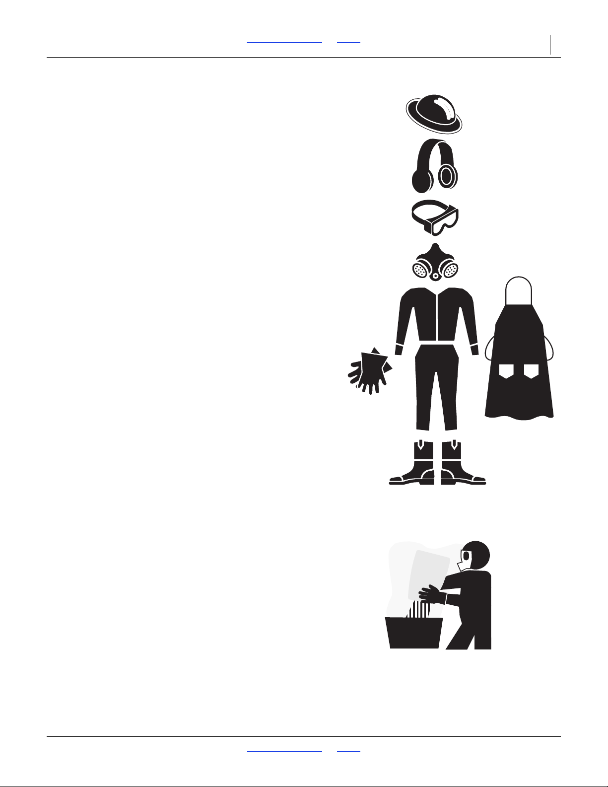
Great Plains advises all users of chemical pesticides or
herbicides to use the following personal safety
equipment.
Waterproof, wide-brimmed hat
Waterproof apron.
Face shield, goggles or full face respirator.
Goggles with side shields or a full face respirator is
required if handling or applying dusts, wettable powders,
or granules or if being exposed to spray mist.
Cartridge-type respirator approved for pesticide vapors
unless label specifies another type of respirator.
Waterproof, unlined gloves. Neoprene gloves are
recommended.
Cloth coveralls/outer clothing changed daily; waterproof
items if there is a chance of becoming wet with spray
Waterproof boots or foot coverings
Do not wear contaminated clothing. Wash protective
clothing and equipment with soap and water after each
use. Personal clothing must be laundered separately from
household articles.
Clothing contaminated with certain pesticides must be
destroyed according to state and local regulations. Read
chemical label for specific instructions.
Wear clothing and equipment appropriate for the job.
Avoid loose-fitting clothing.
Prolonged exposure to loud noise can cause hearing
impairment or loss. Wear suitable hearing protection such
as earmuffs or earplugs.
Avoid wearing entertainment headphones while operating
machinery. Operating equipment safely requires the full
attention of the operator.
Handle Chemicals Properly
Agricultural chemicals can be dangerous. Improper use
can seriously injure persons, animals, plants, soil and
property.
Read and follow chemical manufacturer’s instructions.
Wear protective clothing.
Handle all chemicals with care.
Avoid inhaling smoke from any type of chemical fire.
Store or dispose of unused chemicals as specified by
chemical manufacturer.
2017-10-26 Table of Contents Index 195-325M
Page 7
3S-5000/F/HD/HDF Table of Contents Index Important Safety Information 3
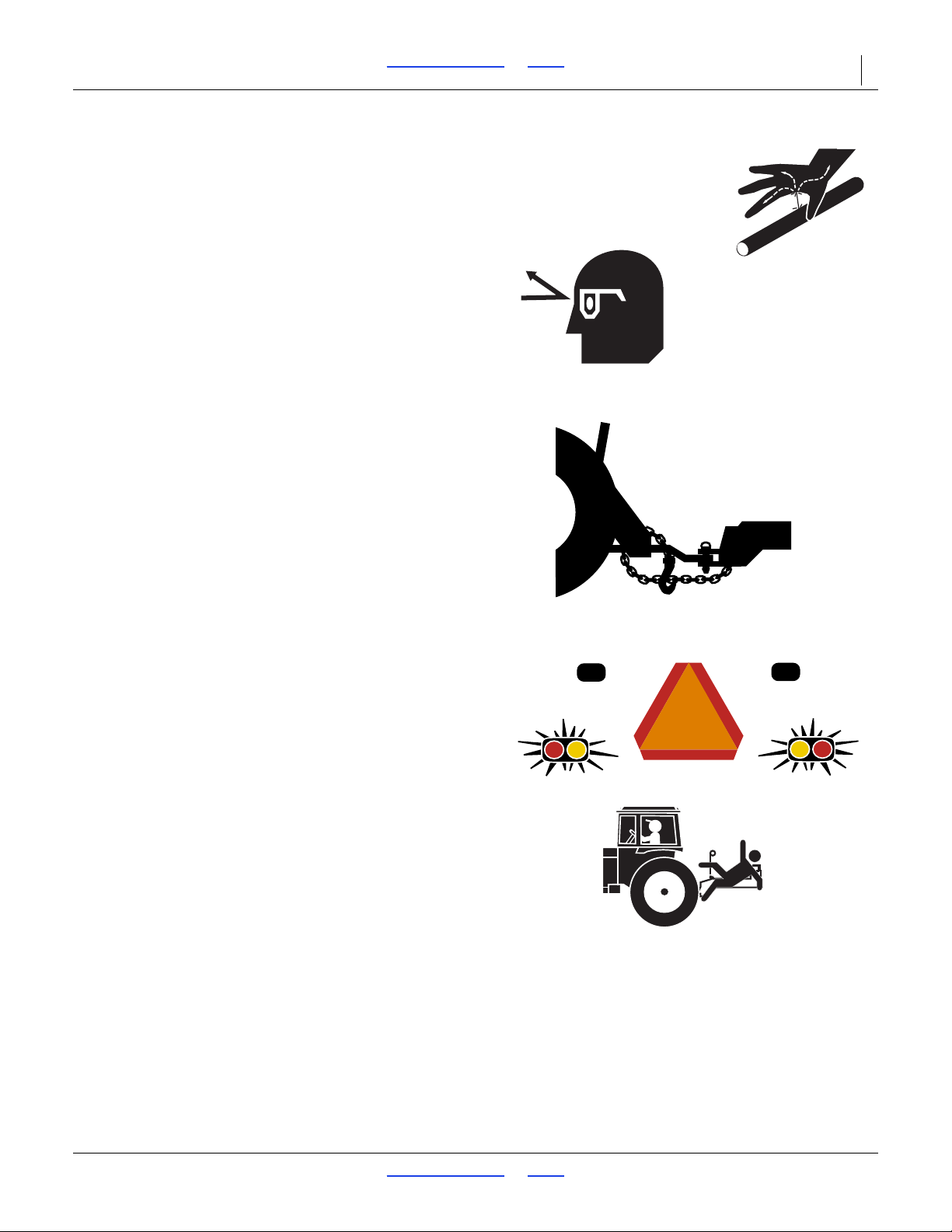
Avoid High Pressure Fluids
Escaping fluid under pressure can penetrate the skin,
causing serious injury.
Avoid the hazard by relieving pressure before
disconnecting hydraulic lines.
Use a piece of paper or cardboard, NOT BODY PARTS, to
check for suspected leaks.
Wear protective gloves and safety glasses or goggles when
working with hydraulic systems.
If an accident occurs, seek immediate medical assistance
from a physician familiar with this type of injury.
Use A Safety Chain
Use a safety chain to help control drawn machinery
should it separate from tractor draw-bar.
Use a chain with a strength rating equal to or greater than
the gross weight of towed machinery.
Attach chain to tractor draw-bar support or other
specified anchor location. Allow only enough slack in
chain to permit turning.
Replace chain if any links or end fittings are broken,
stretched or damaged.
Do not use safety chain for towing.
Use Safety Lights and Devices
Slow-moving tractors and towed implements can create
a hazard when driven on public roads. They are difficult
to see, especially at night.
Use flashing warning lights and turn signals whenever
driving on public roads.
Use lights and devices provided with implement
Keep Riders Off Machinery
Riders obstruct the operator’s view. Riders could be
struck by foreign objects or thrown from the machine.
Never allow children to operate equipment.
Keep all bystanders away from machine during operation.
2017-10-26 Table of Contents Index 195-325M
Page 8
3S-5000/F/HD/HDF Table of Contents Index Important Safety Information 4
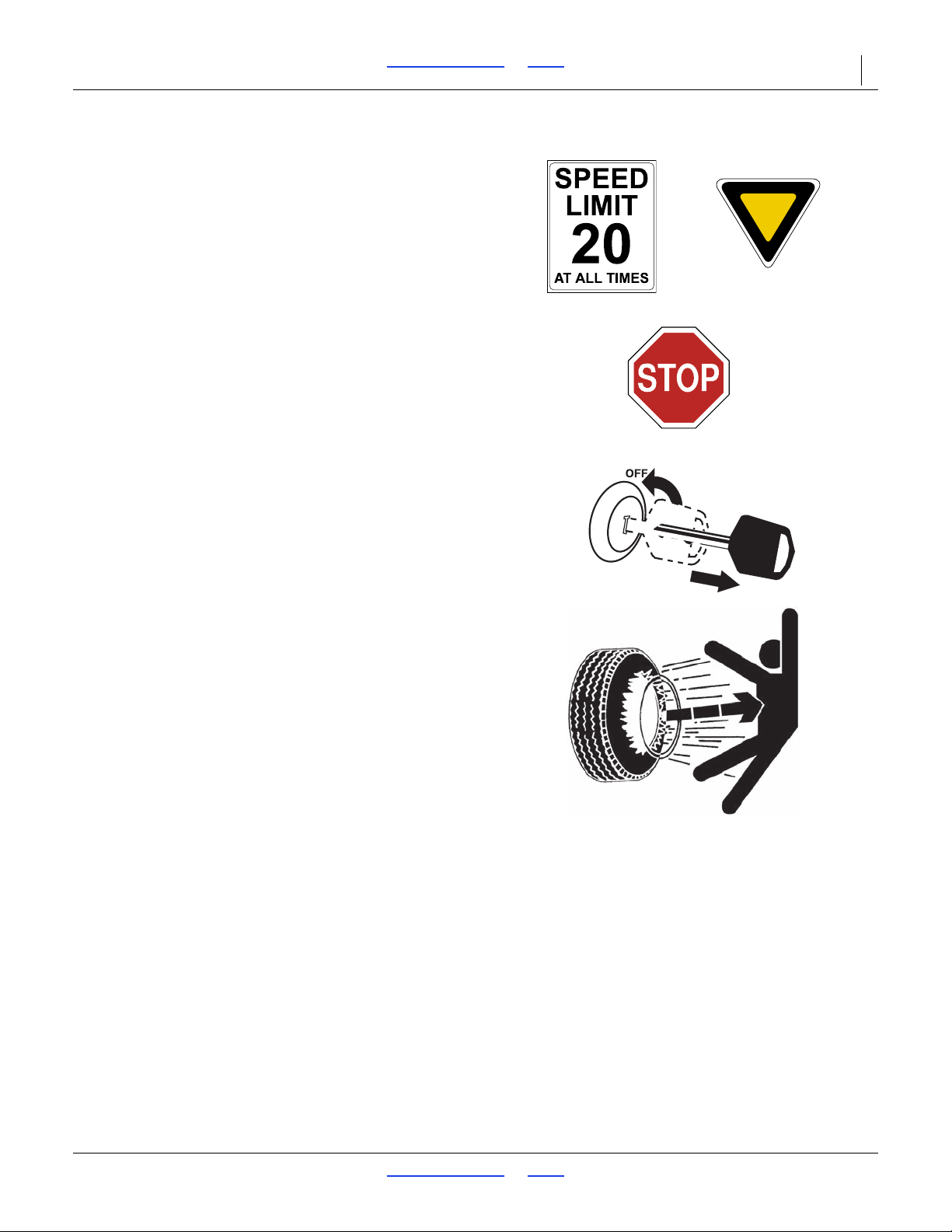
Transport Machinery Safely
Maximum transport speed for implement is 20 mph (32
kph). Some rough terrains require a slower speed.
Sudden braking can cause a towed loa d to swerve and
upset.
Do not exceed 20 mph. Never travel at a speed which does
not allow adequate control of steering and stopping.
Reduce speed if towed load is not equipped with brakes.
Comply with state and local laws.
Do not tow an implement that, when fully loaded, weighs
more than 1.5 times the weight of towing vehicle.
Carry reflectors or flags to mark drill in case of
breakdown on the road.
Do not fold or unfold the drill while the tractor is moving.
Shutdown and Storage
Lower drill, put tractor in park, turn off engine, and
remove the key.
Secure drill using blocks and supports provided.
Detach and store drill in an area where children normally
do not play.
Tire Safety
Tire changing can be dangerous and should be
performed by trained personnel using correct tools and
equipment.
When inflating tires, use a clip-on chuck and extension
hose long enough for you to stand to one side–not in front
of or over tire assembly. Use a safety cage if available.
When removing and installing wheels, use wheel-handling
equipment adequate for weight involved.
2017-10-26 Table of Contents Index 195-325M
Page 9
3S-5000/F/HD/HDF Table of Contents Index Important Safety Information 5
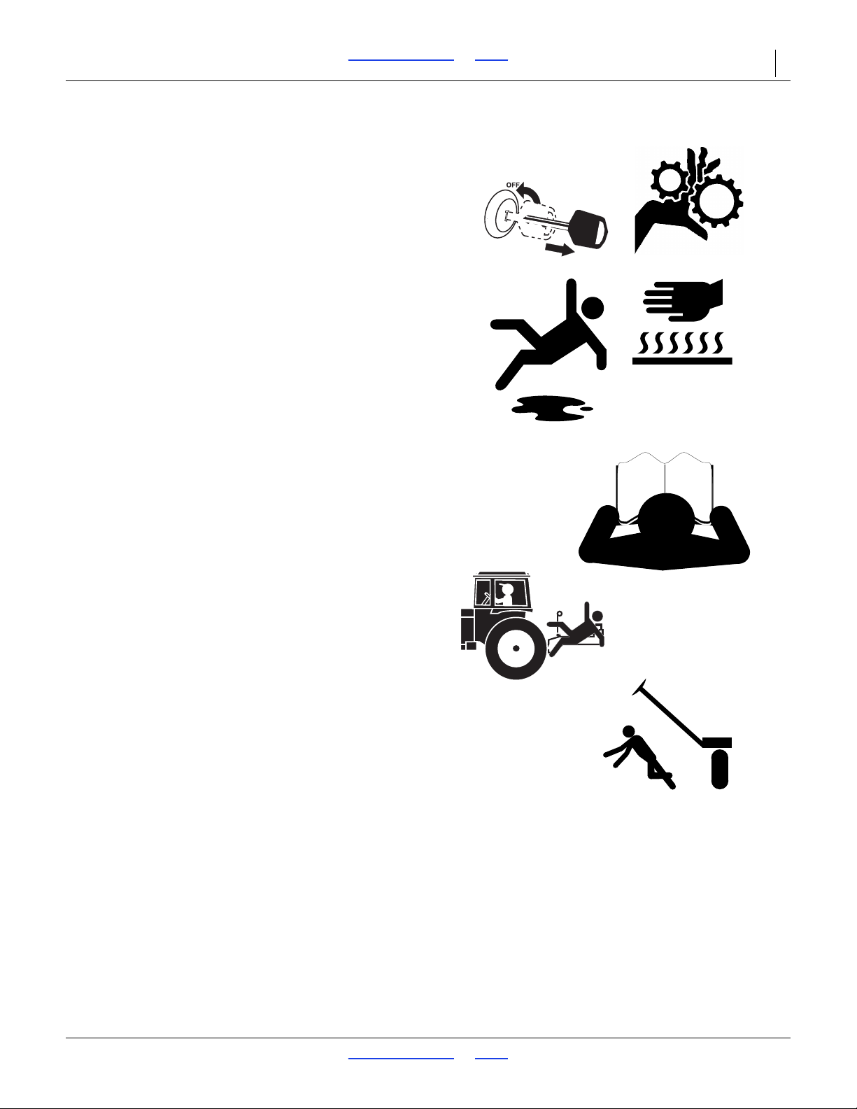
Practice Safe Maintenance
Understand procedure before doing work. Use proper
tools and equipment. Refer to this manual for additional
information.
Work in a clean, dry area.
Lower the drill, put tractor in park, turn off engine, and
remove key before performing maintenance.
Make sure all moving parts have stopped and all system
pressure is relieved.
Allow drill to cool completely.
Disconnect battery ground cable (-) before servicing or
adjusting electrical systems or before welding on drill.
Inspect all parts. Make sure parts are in good condition
and installed properly.
Remove buildup of grease, oil or debris.
Remove all tools and unused parts from drill before
operation.
Safety At All Times
Thoroughly read and understand the instructions in this
manual before operation. Read a ll instructions noted on
the safety decals.
Be familiar with all drill functions.
Operate machinery from the driver’s seat only.
Do not leave drill unattended with tractor engine running.
Do not dismount a moving tractor. Dismounting a moving
tractor could cause serious injury or death.
Do not stand between the tractor and drill during
hitching.
Keep hands, feet and clothing away from power-driven
parts.
Wear snug-fitting clothing to avoid entanglement with
moving parts.
Watch out for wires, trees, etc., when folding and raising
drill. Make sure all persons are clear of working area.
2017-10-26 Table of Contents Index 195-325M
Page 10
3S-5000/F/HD/HDF Table of Contents Index Important Safety Information 6
To install new decals:
1. Clean the area on which the decal is to be placed.
2. Peel backing from decal. Press firmly on surface,
being careful not to cause air bubbles under decal.
34283
34284
68380A
Safety Decals
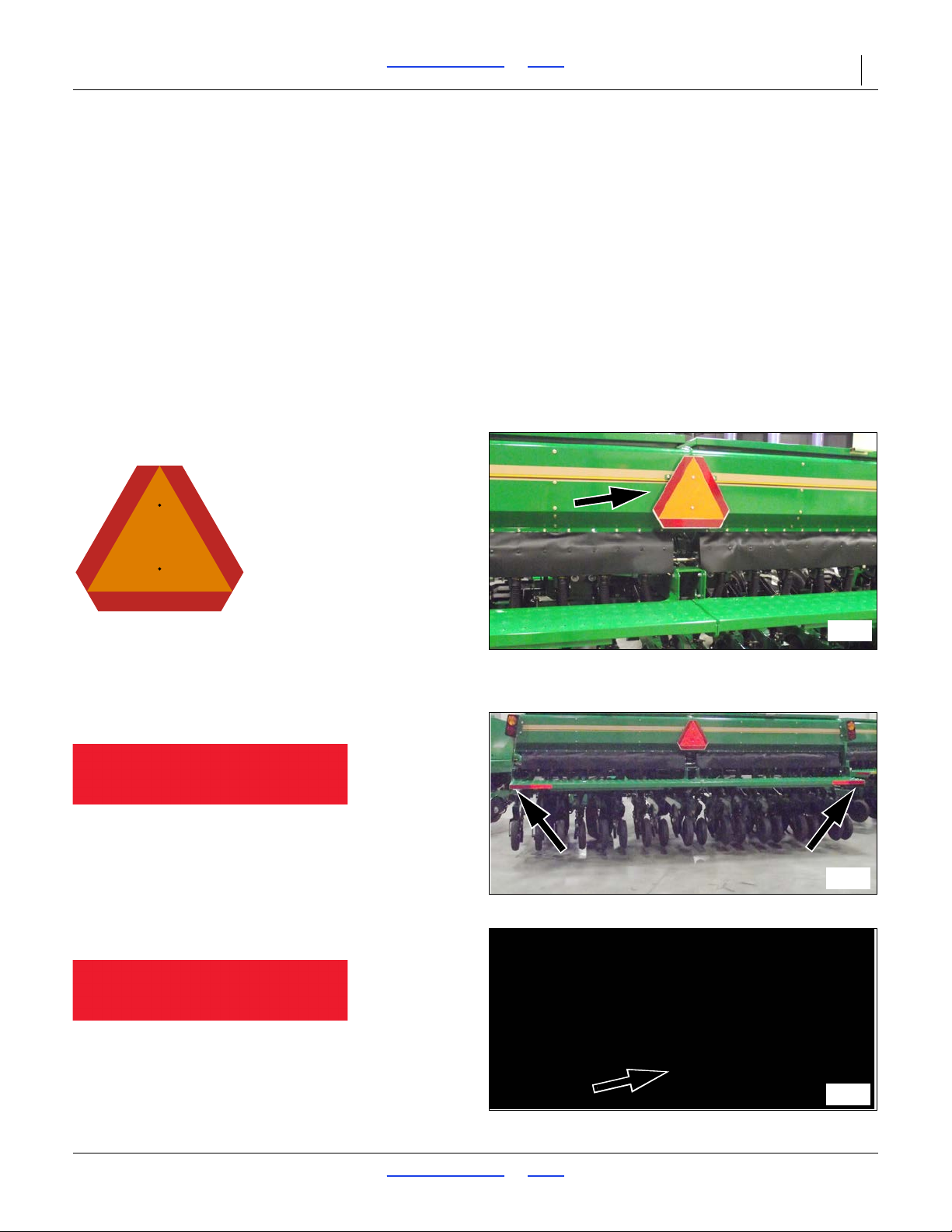
Safety Reflectors and Decals
Your implement comes equipped with all lights, safety
reflectors and decals in place. They were designed to
help you safely operate your implement.
Read and follow decal directions.
Keep lights in operating condition.
Keep all safety decals clean and legible.
Replace all damaged or missing decals. Order new decals
from your Great Plains dealer. Refer to this section for
proper decal placement.
When ordering new parts or components, also request
corresponding safety decals.
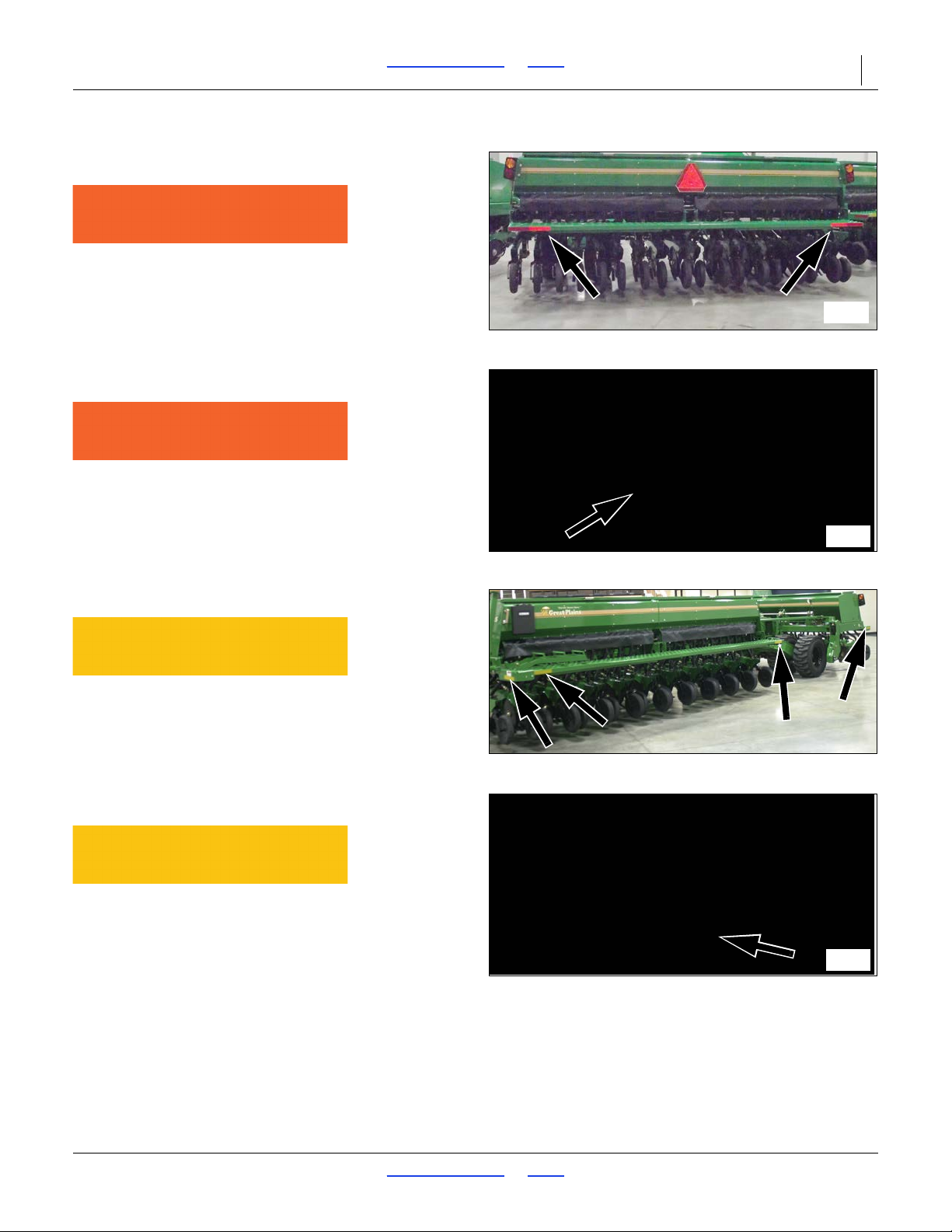
Slow Moving Vehicle Reflector
818-055C
On center section;
1 total
Red Reflectors (S/N C1304L-)
838-266C
On rear of center section, one each outside corner;
2 total
Red Reflectors (S/N C1305L+)
838-266C
On rear of center section, one on decal bracket at each
end;
2 total
2017-10-26 Table of Contents Index 195-325M
Page 11
3S-5000/F/HD/HDF Table of Contents Index Important Safety Information 7
34284
68380A
34300
68380A
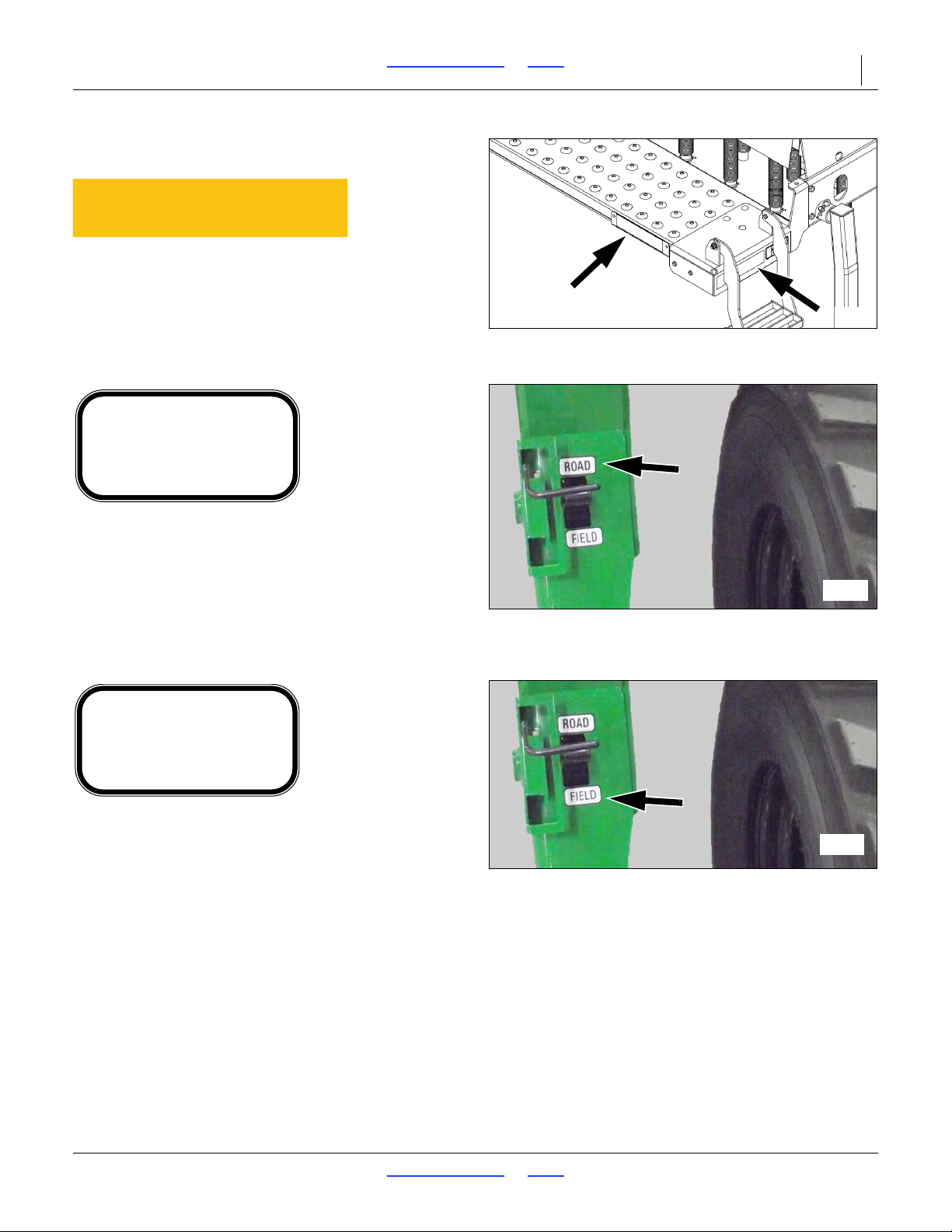
Daytime Reflectors (S/N C1304L-)
838-267C
On rear of center section;
2 total
Daytime Reflectors (S/N C1305L+)
838-267C
On rear of center section, one on decal bracket at each
end;
2 total
Amber Reflectors (S/N C1304L-)
838-265C
Three reflectors on each wing section, one reflector
on each end of center section;
8 total
Amber Reflectors (S/N C1 305L+)
838-265C
One reflector on each end of center section;
2 total
2017-10-26 Table of Contents Index 195-325M
Page 12
3S-5000/F/HD/HDF Table of Contents Index Important Safety Information 8
68380B
34285
34285
FIELD
P.N. 818-258C
Amber Reflectors (S/N C1 305L+)
838-265C
One on decal bracket at each end of wings, one on
outside end of wings;
6 total
Transport Lock Road
818-257C
RO AD
P.N. 818-257C
Place above lever: two each RH and LH end section,
two on center section;
6 total
Transport Lock Field
818-258C
Place below lever: two each RH and LH end section,
two on center section;
6 total
2017-10-26 Table of Contents Index 195-325M
Page 13
3S-5000/F/HD/HDF Table of Contents Index Important Safety Information 9
34287
34288
WARNING
NEGA TIVE TONGUE WEIGHT
HAZARD
Negative tongue weight can cause immediate
elevation of tongue when unhitching implement
To prevent serious injury or death:
Always be certain implement is hitched securely
to tractor drawbar before raising.
Lower implement BEFORE unhitching.
818-019C Rev. D
34289
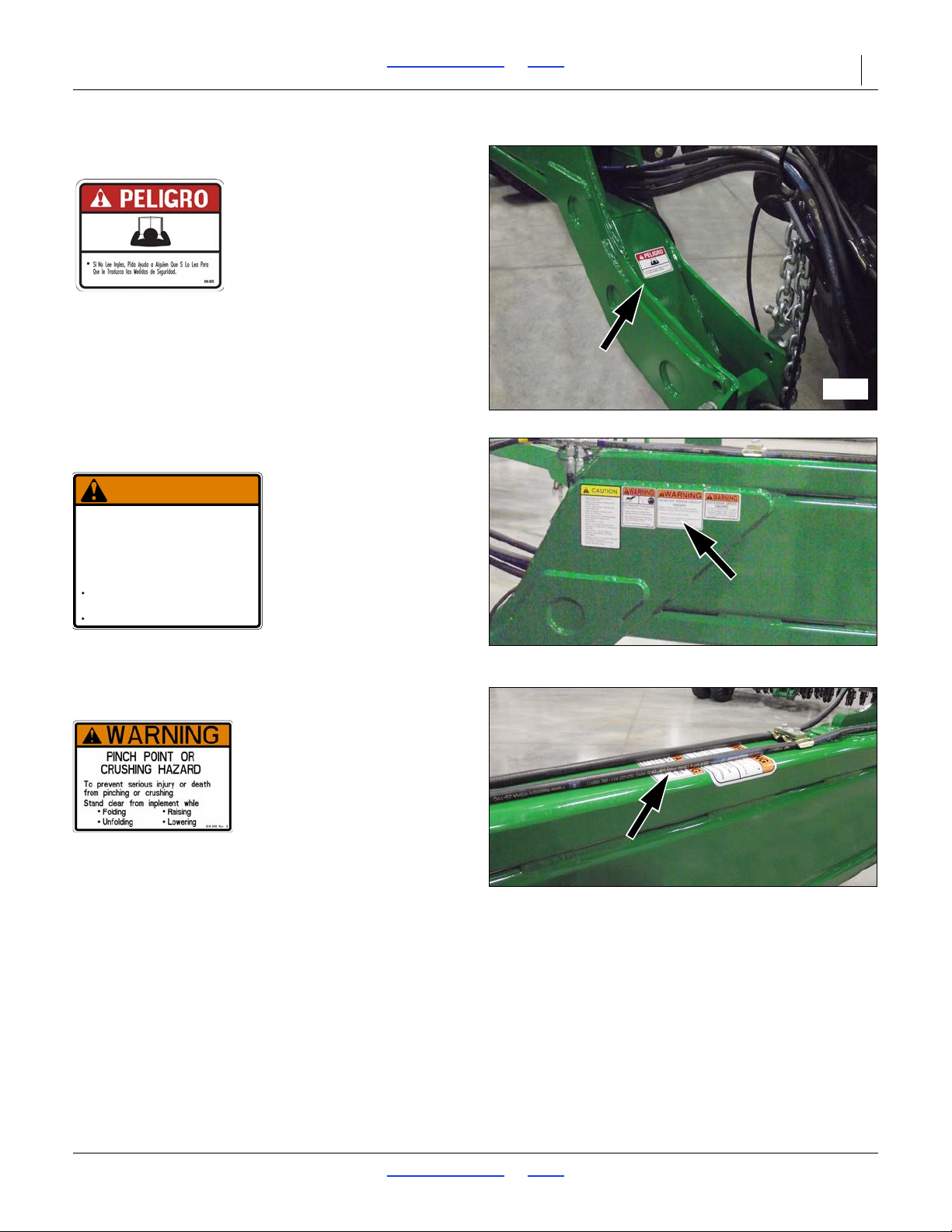
Danger (in Spanish):
818-557C
Advising non-English readers to seek translation
On tongue, at hitch;
1 total
Warning: Negative Tongue Weight Hazard
818-019C
On the tongue;
1 total
Warning: Pinch/Crush
818-045C
On top of tongue;
1 total
2017-10-26 Table of Contents Index 195-325M
Page 14
3S-5000/F/HD/HDF Table of Contents Index Important Safety Information 10
34288
818-188C Rev. C
Do Not exceed 20 mph maximum transport
speed. Loss of vehicle control and/or machine
can result.
To Prevent Serious Injury or Death:
EXCESSIVE SPEED HAZARD
WARNING
34288
34289
WARNING
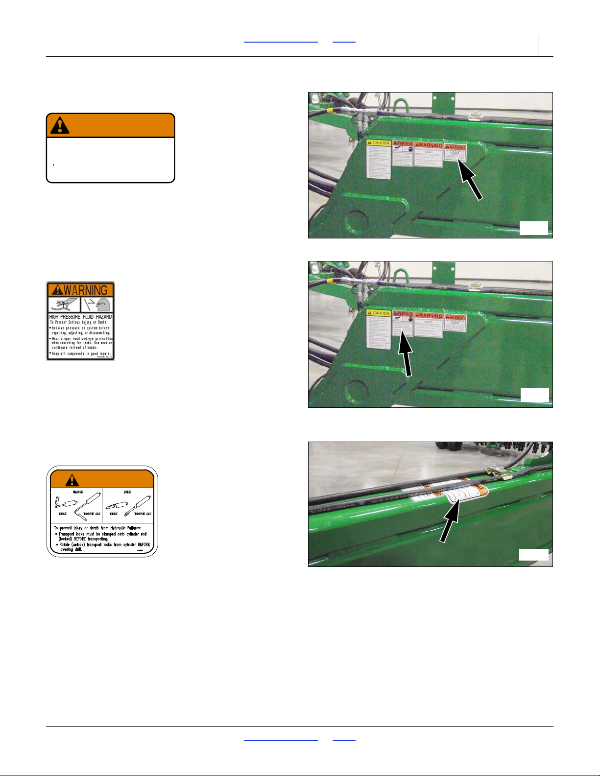
Warning: Speed
818-188C
On left side of tongue,
1 total
Warning: High Pressure Fluid Hazard
818-339C
On left side of tongue;
1 total
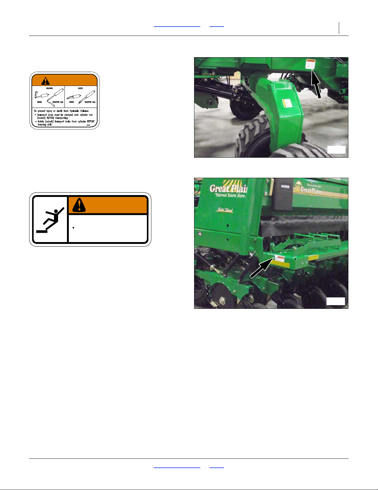
Warning: Transport Lock
818-660C
On top of tongue;
1 total
2017-10-26 Table of Contents Index 195-325M
Page 15
3S-5000/F/HD/HDF Table of Contents Index Important Safety Information 11
34290
WARNING
34291
WARNING
To avoid serious injury or death:
Watch your step when climbing ladder or
walking on walkboard.
838-102C
Warning: Transport Lock
818-660C
One on each side of drill frame;
2 total
Warning: Falling Hazard
838-102C
One decal on each end of the drill;
2 total
2017-10-26 Table of Contents Index 195-325M
Page 16
3S-5000/F/HD/HDF Table of Contents Index Important Safety Information 12
34288
CAUTION
34290
34295
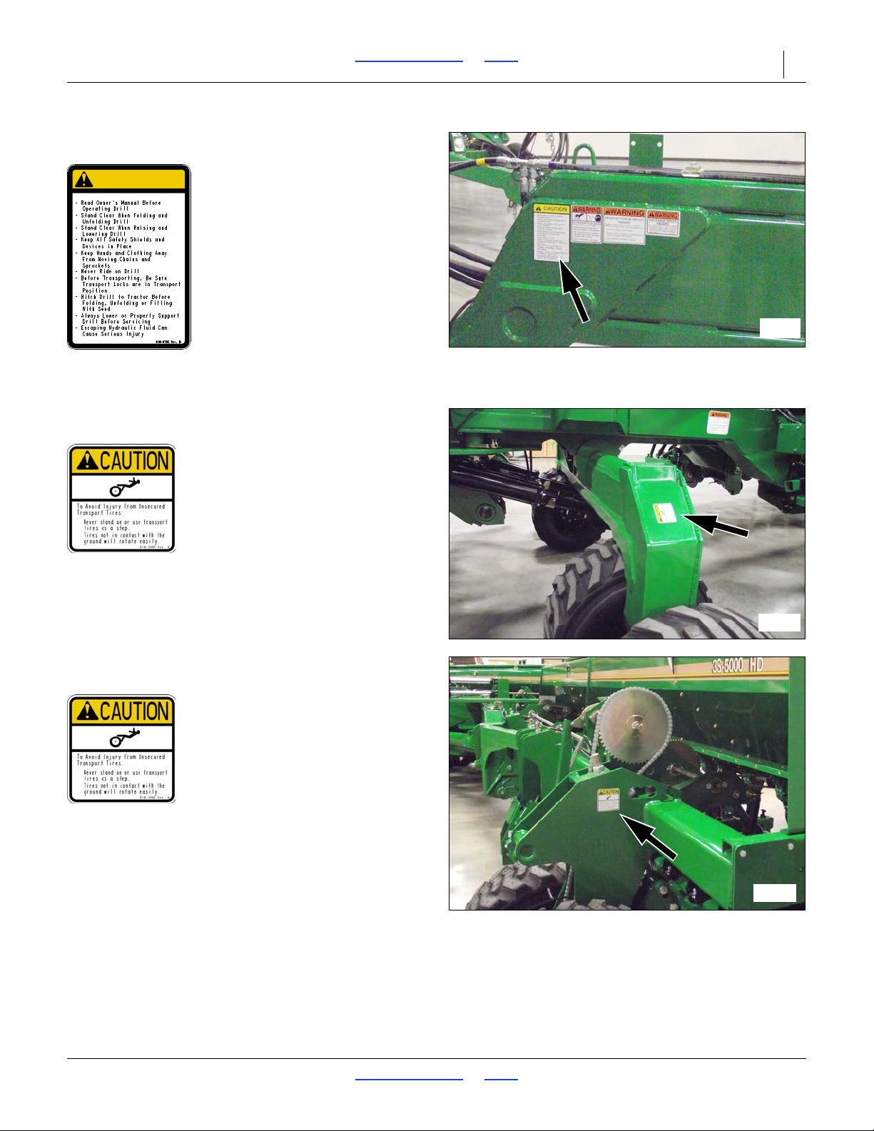
Caution: General Instructions
818-078C
On tongue;
1 total
Caution: Tires Not A Step
818-398C
One on each transport axle leg;
2 total
Caution: Tires Not A Step
818-398C
One on outside face each gauge wheel weldment;
2 total
2017-10-26 Table of Contents Index 195-325M
Page 17
3S-5000/F/HD/HDF Table of Contents Index Important Safety Information 13
34298
34292
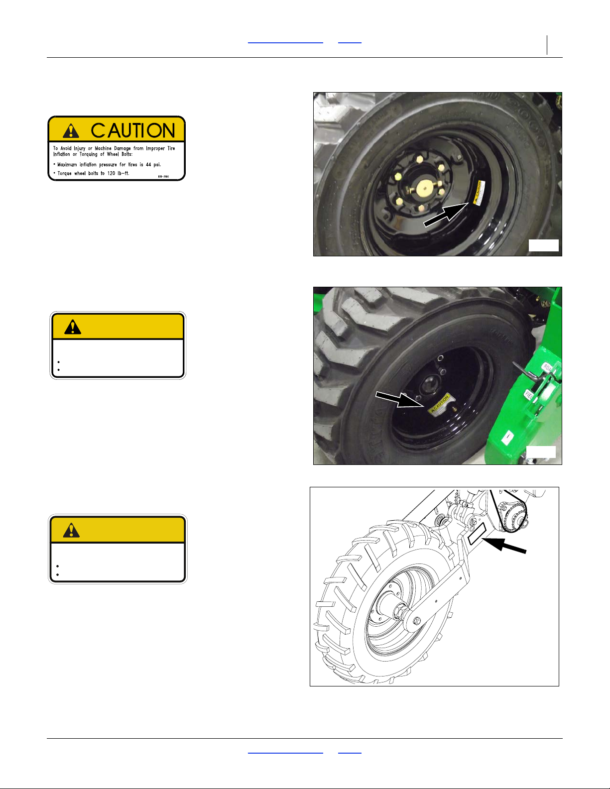
To Avoid Injury or Machine Damage from Improper Tire
Inflation or Torquing of Wheel Bolts:
Maximum inflation pressure of tires is 80 psi.
Torque wheel bolts to 300 lb-ft.
848-801C
CAUTION
36288
858-781C
Maximum inflation pressure of tires is 40 psi.
Torque wheel bolts to 120 ft-lbs.
To Avoid Injury or Machine Damage from Improper Tire
Inflation or Torquing of Wheel Bolts:
CAUTION
Caution: Tire Pressure and Torque
838-258C
Wing sections: one on each gauge wheel rim;
4 or 0 total
Caution: Tire Inflation and Torque
848-801C
Center section: one on each transport wheel rim;
4 or 0 total
Caution: Tire Inflation and Torque
858-781C
Liquid fertilizer drive: on side of wheel fork;
1 total
2017-10-26 Table of Contents Index 195-325M
Page 18
3S-5000/F/HD/HDF Table of Contents Index Introduction 14
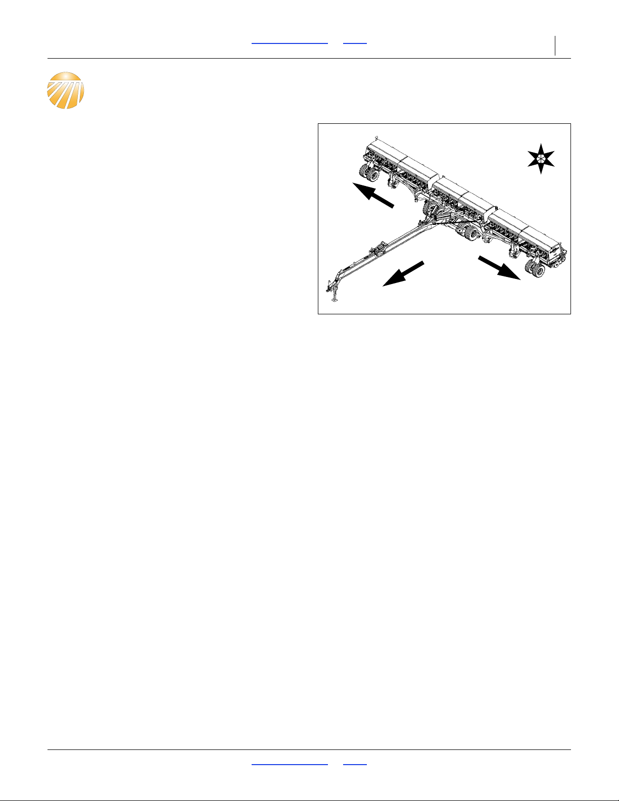
Figure 1
3S-5000/F/HD/HDF Drill
34310
U
D
F
B
L
R
L
R
Introduction
Great Plains welcomes you to its growing family of new
product owners. The 3-Section 50 Foot Folding Drill
(3S-5000/F/HD/HDF) has been designed with care and
built by skilled workers using quality materials. Proper
setup, maintenance, and safe operating practices will
help you get years of satisfactory use from the machine.
Description of Unit
The 3S-5000/F/HD/HDF Drill is a towed seeding
implement for use in conventional or minimum tillage
conditions. This three section drill has a working width of
50 feet (12.2 m). The drill has straight arm, double disk
openers. The opener disks make a seed bed, and seed
tubes mounted between the disks place seed in the
furrow. Press wheels following the op ener disks close the
furrow and gauge opener seeding depth. A T-handle on
the opener body is for seeding depth adjustments.
Seeding rates are adjustable with the seed rate
adjustment handle and sprocket changes.
The 3S-5000/F/HD/HDF features active hydraulic down
pressure on the opener frames. When used on a tractor
with closed-center hydraulics, constant down pressure
ensures even opener penetration in uneven ground.
Hydraulic down pressure is adjustable at a single point.
Intended Usage
Use the 3S-5000/F/HD/HDF Drill to seed
production-agriculture crops only. Do not modify the drill
for use with attachments other than Great Plains options
and accessories specified for use with the 3S-5000 Drill
Models Covered
3S-5000-6010 60 Row, 10 inch (25.4 cm) Spacing
3S-5000-8075 80 Row, 7.5 inch (19.1 cm) Spacing
3S-5000-1006 100 Row, 6 inch (15.2 cm) Spacing
3S-5000F-6010 60 Row, 10 inch (25.4 cm) Spacing
3S-5000F-8075 80 Row, 7.5 inch (19.1 cm) Spacing
3S-5000F-1006 100 Row, 6 inch (15.2 cm) Spacing
3S-5000HD-6010 60 Row, 10 inch (25.4 cm) Spacing
3S-5000HD-8075 80 Row, 7.5 inch (19.1 cm) Spacing
3S-5000HD-1006 100 Row, 6 inch (15.2 cm) Spacing
3S-5000HDF-6010 60 Row, 10 inch (25.4 cm) Spacing
3S-5000HDF-8075 80 Row, 7.5 inch (19.1 cm) Spacing
3S-5000HDF-1006 100 Row, 6 inch (15.2 cm) Spacing
Document Family
195-325M Owner’s Manual (this document)
2017-10-26 Table of Contents Index 195-325M
195-325B Seed Rate Charts
133-322M Small Seeds Manual
195-325P Parts Manual
Page 19

3S-5000/F/HD/HDF Table of Contents Index Introduction 15
U
D
F
B
L
R
Using This Manual
This manual will familiarize you with safety, assembly,
operation, adjustments, troubleshooting, and
maintenance. Read this manual and follow the
recommendations to help ensure safe and efficient
operation.
The information in this manual is current at printing.
Some parts may change to assure top performance.
Definitions
The following terms are used throughout this manual.
Right-hand and left-hand as used in
this manual are determined by facing
the direction the machine will travel
while in use unless otherwise stated.
An orientation rose in some line art
illustrations shows the directions of:
Up, Back, Left, Down, Front, Right.
A crucial point of information related to the current topic. Read
and follow the directions to remain safe, avoid serious damage
to equipment and ensure desi red field results.
NOTE:
Useful information related to the preceding topic.
2017-10-26 Table of Contents Index 195-325M
Page 20
3S-5000/F/HD/HDF Table of Contents Index Introduction 16
Figure 2
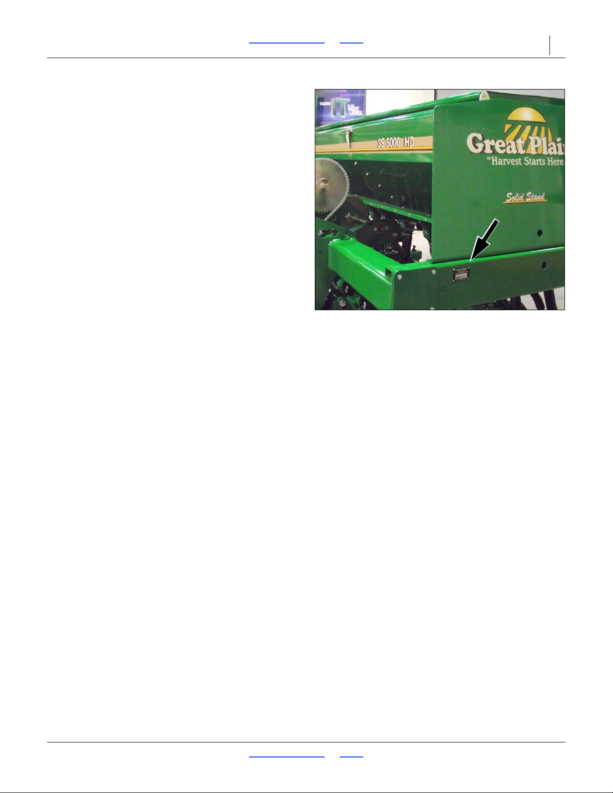
Serial Number Plate
34299
Owner Assistance
If you need customer service or repair parts, contact a
Great Plains dealer. They have trained personnel, repair
parts and equipment specially designed for Great Plains
products.
Refer to Figure 2
Your machine’s parts were specially designed and
should only be replaced with Great Plains parts. Always
use the serial and model number when ordering parts
from your Great Plains dealer. The serial-number plate is
located on the left end of seed box frame, as shown.
Record your 3S-5000/F/HD/HDF Drill model and serial
number here for quick reference:
Model Number:__________________________
Serial Number: __________________________
Further Assistance
Great Plains Manufacturing, Inc. and your Great Plains
dealer want you to be satisfied with your new drill. If for
any reason you do not understand any part of this
manual or are otherwise dissatisfied, please take the
following actions first:
1. Discuss the matter with your dealership service
manager . Make sure th ey are aware of a ny prob lems
so they can assist you.
2. If you are still unsatisfied, seek out the owner or
general manager of the dealership.
If your dealer is unable to resolve the problem or the
issue is parts related, please contact:
Great Plains Service Department
Or go to www.greatplainsag.com and follow the contact
information at the bottom of your screen for our service
department.
2017-10-26 Table of Contents Index 195-325M
1525 E. North St.
P.O. Box 5060
Salina, KS 67402-5060
Page 21
3S-5000/F/HD/HDF Table of Contents Index Preparation and Setup 17
Spill hazard/Tank damage risk:
Periodically check the tension of the straps for the fertilizer
tank. Strap tension will change as outside air temperature
changes. Adjust tension as necessary to prevent personal
injury or damage to the fertilizer tank.
Do not use petroleum based products on feeder cup or small
grass cup components.
Preparation and Setup
This section helps you prepare your tractor and
3S-5000/F/HD/HDF Drill for use.You must level the drill,
adjust drill tongue height to match your tractor drawbar
height, hook up the drill hydraulics to the tractor, and
check that the hydraulics have been bled.
Post-Delivery/Seasonal Setup
On initial delivery, use with a new tractor, and seasonally,
check and as necessary, complete these items before
continuing to the routine setup items:
• Bleed hydraulic system (page 73).
• Wing leveling and alignment (page 19).
• Marker setup (page 47)
• De-grease exposed cylinder rods if so protected at
last storage.
Pre-Planting Setup
Complete this checklist before routine setup:
Read and understand “Important Safety
Information” on page 1.
Check that all working parts are moving freely, bolts
are tight, and cotter pins are spread.
Check that all grease fittings are in place and
lubricated. See “Lubrication” on page 83.
Check that all safety decals and reflectors are
correctly located and legible. Replace if damaged.
See “Safety Decals” on page 6.
Inflate tires to pressure recommended and tighten
wheel bolts as specified. See “Specifications and
Capacities” on page 96.
2017-10-26 Table of Contents Index 195-325M
Page 22
3S-5000/F/HD/HDF Table of Contents Index Preparation and Setup 18
Figure 3
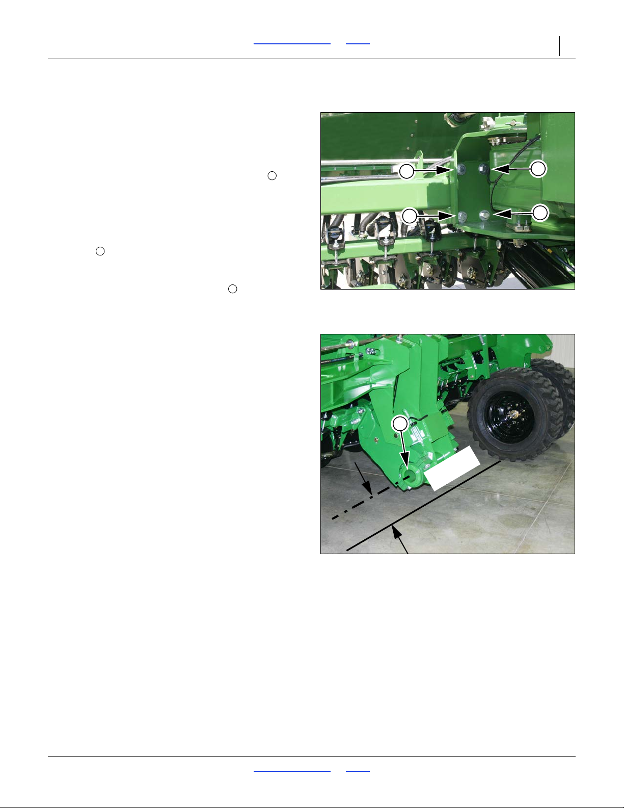
Center Box Mount Bolts
34319
1
1
1
1
121
Figure 4
Opener Frame Leveling
34297
2
O
p
e
n
e
r
Leveling the Drill
Center Box Frame Leveling
1. Park the drill on a clean level surface.
2. Raise the openers and lock them up.
Refer to Figure 3
3. Loosen the eight center box mount bolts , four
bolts on each side of tongue and slide center box
frame sideways until it is centered with mainframe
and transport axle.
Refer to Figure 4
4. Measure the height of center box opener frame
pivots from the level surface and raise low end of
box frame up until both opener frame pivots measure
the same distance from the ground.
5. Torque the
Opener Frames
Check that opener frames are level across drill. When
fully raised, top of opener mounts should clear bottom of
drill frame tube by at least
“Opener Frame Clearance” on page 55, for further
instructions.
7
/8inch box mount bolts .
1
/2inch (13 mm). See
2017-10-26 Table of Contents Index 195-325M
Page 23
3S-5000/F/HD/HDF Table of Contents Index Preparation and Setup 19
Figure 5
Stop Bolt Location
18988
Stop Bolt
Figure 6
Wing Box Alignment Measurement
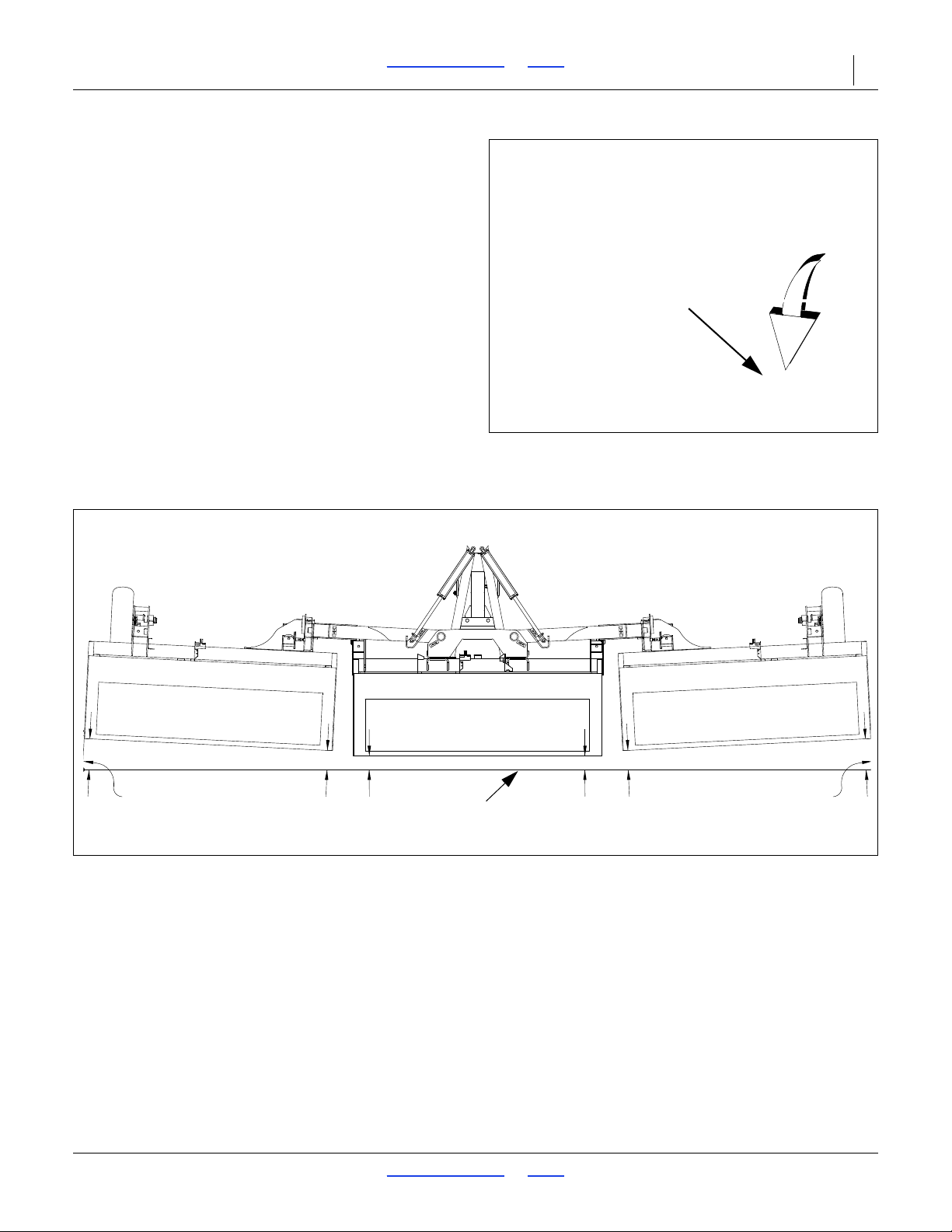
15654
String Line
String Line
Support
String Line
Support
A
A
B
B
C-B=1 to 11/4 inch
Wing Box Alignment
1. Place a block ahead of the wing gauge wheels.
Refer to Figure 5
2. Pull forward against blocks to rock wing frames
back. Pull forward until stop bolts are firmly against
tool bars.
Refer to Figure 6
3. Check for proper alignment by running a string line
across back of drill toward outer ends of wings. For
proper alignment, outside ends of boxes should be
about 1 inch to 1
inside ends.
4. To adjust box alignment, shorten or lengthen stop
bolts to change the contact p oint with the tool bars.
Adjust stop bolts in or out until outside ends of boxes
are 1 inch to 1
ends.
1
/4inch (25 to 32 mm) ahead of
1
/4inch (25 to 32 mm) ahead of inside
Tool Bar Height
Tool bar height is factory set and normally will not require
adjustment. If the tool bar is visibly not level see “Tool
Bar Height Adjustment” on page 53.
2017-10-26 Table of Contents Index 195-325M
Page 24
3S-5000/F/HD/HDF Table of Contents Index Preparation and Setup 20
1
2
Figure 7
Transfer Drive Shaft Vertical Adjustment
34381
1
2
Align Transfer Drive Shaft
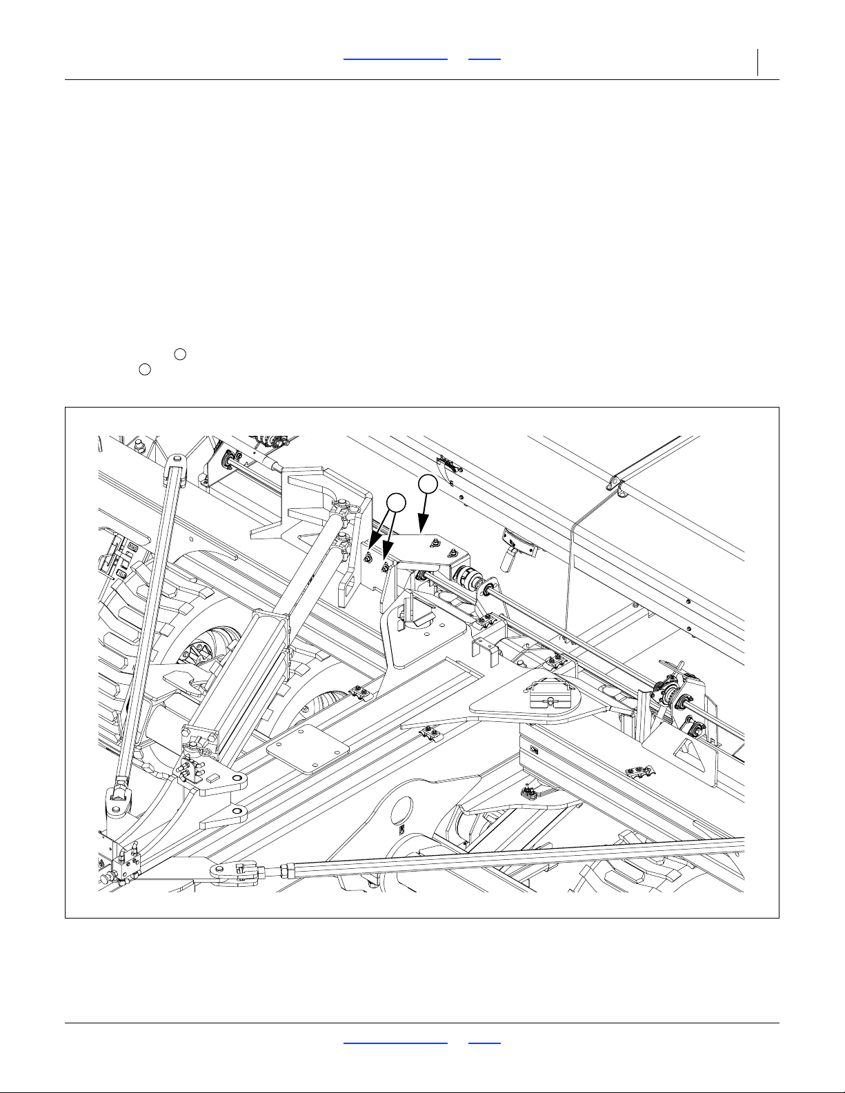
After wing boxes are properly aligned, the transfer drive
shaft must be aligned so the pair of break-away jaws are
fully engaged and are concentric. The
hex drive shafts holding the clutch jaws should not
contact each other when wing boxes are properly aligned
and back against their stops.
1. Place a 4x4 inch or similar sized block ahead of the
wing gauge wheels and pull forward or push wing
box frames back until the tool bar is firmly against
tool bar stop bolts on the center box frame.
Refer to Figure 7
2. To align the clutch jaws vertically, loosen the two
5
/8inch bolts on the backside of the adjustment
bracket . Slide the bracket up or down in the
desired direction.
7
/8inch (19 mm)
2017-10-26 Table of Contents Index 195-325M
Page 25

3S-5000/F/HD/HDF Table of Contents Index Preparation and Setup 21
3
434
Figure 8
Transfer Drive Shaft Vertical Adjustment
34381
3
2
4
Figure 9
Hex Shafts
18955
1/8 in. (3.2
5
Refer to Figure 8
3. To align the clutch jaws from front to rear, loosen the
1
two
/2inch carriage bolts and slide breakaway
clutch in the desired direction.
4. To adjust clutch jaws for full jaw contact, loosen the
1
two
/2inch carriage bolts and slide breakaway
clutch until jaws on the fixed half of clutch make
full contact with jaws on spring loaded half of clutch
without compressing clutch spring.
Refer to Figure 9
NOTE:
The two
1
/8inches (3.2 mm) between them when the clutch
7
/8inch (19 mm) hex shafts should have
jaws have full contact.
2017-10-26 Table of Contents Index 195-325M
Page 26
3S-5000/F/HD/HDF Table of Contents Index Preparation and Setup 22
Hitching Tractor to Drill
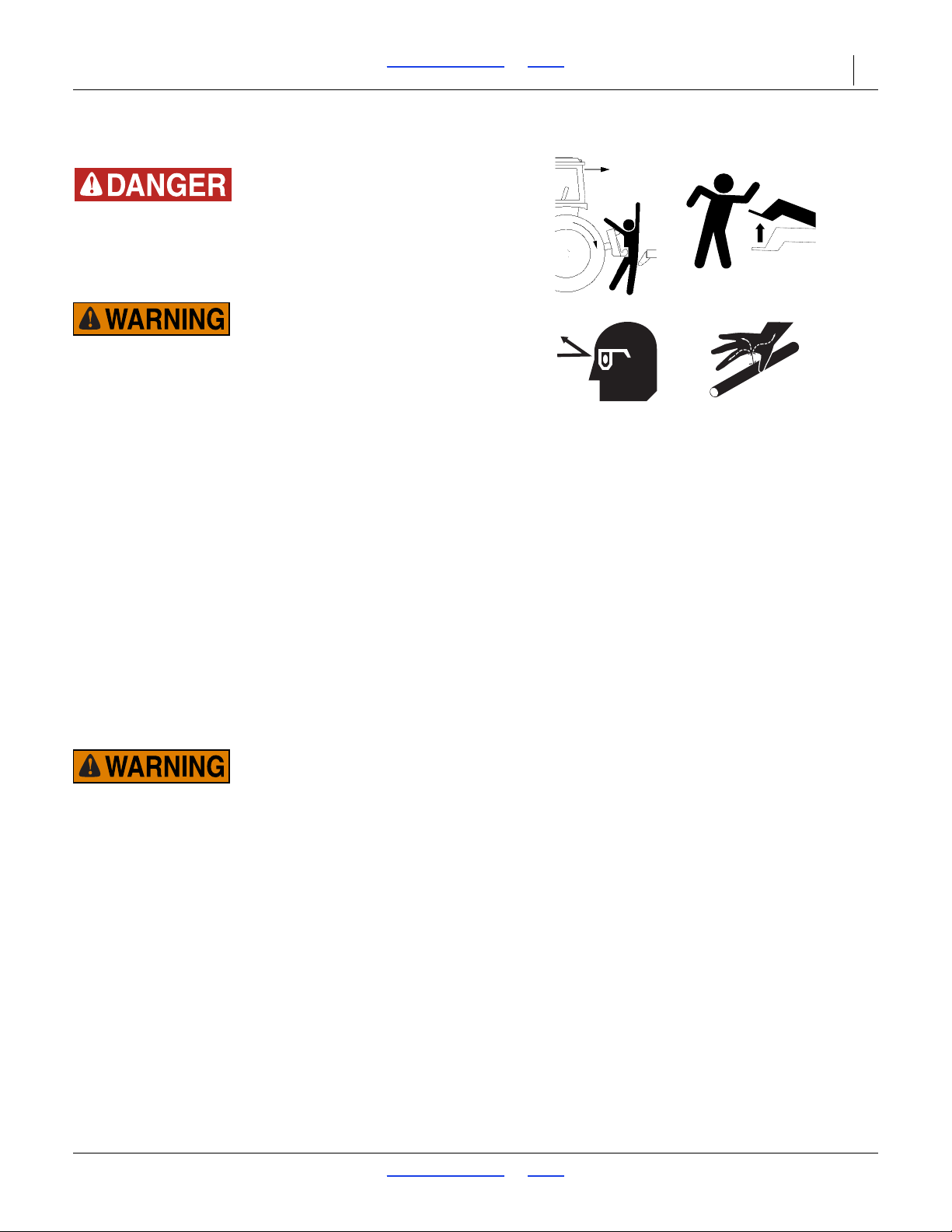
Crushing Hazard:
Do not stand or place any part of your body between drill and
moving tractor. You may be severely injured or killed by being
crushed between the tractor and drill. Stop tractor engine and
set park brake before installing the hitch pin.
Transport Hazard:
This drill can have positive and negative tongue weight, which
can work the hitch pin loose during transport. To avoid serious
injury or death due to a road accident, always use a clevis
hitch or clevis drawbar with a locking-style hitch pin.
1. Choose a drill-hitch option that is compatible with
your tractor drawbar.
The 3S-5000/F/HD/HDF has three hitch options:
• a clevis hitch,
• a small-hole, single-strap hitch or
• a large-hole, single-strap hitch.
Use the clevis hitch with tractors that have
single-tang draw bars. Use the single-strap hitch for
tractors with clevis draw bars. Always use a
locking-style hitch pin sized to match the holes in the
hitch and drawbar.
Adjusting the Drill Hitch
Crushing Hazard:
You may be severely injured or killed by being crushed
between the tractor and drill. Do not stand or place any part of
your body between machines being hitched. Stop tractor
engine and set parking brake before installing hitch pin.
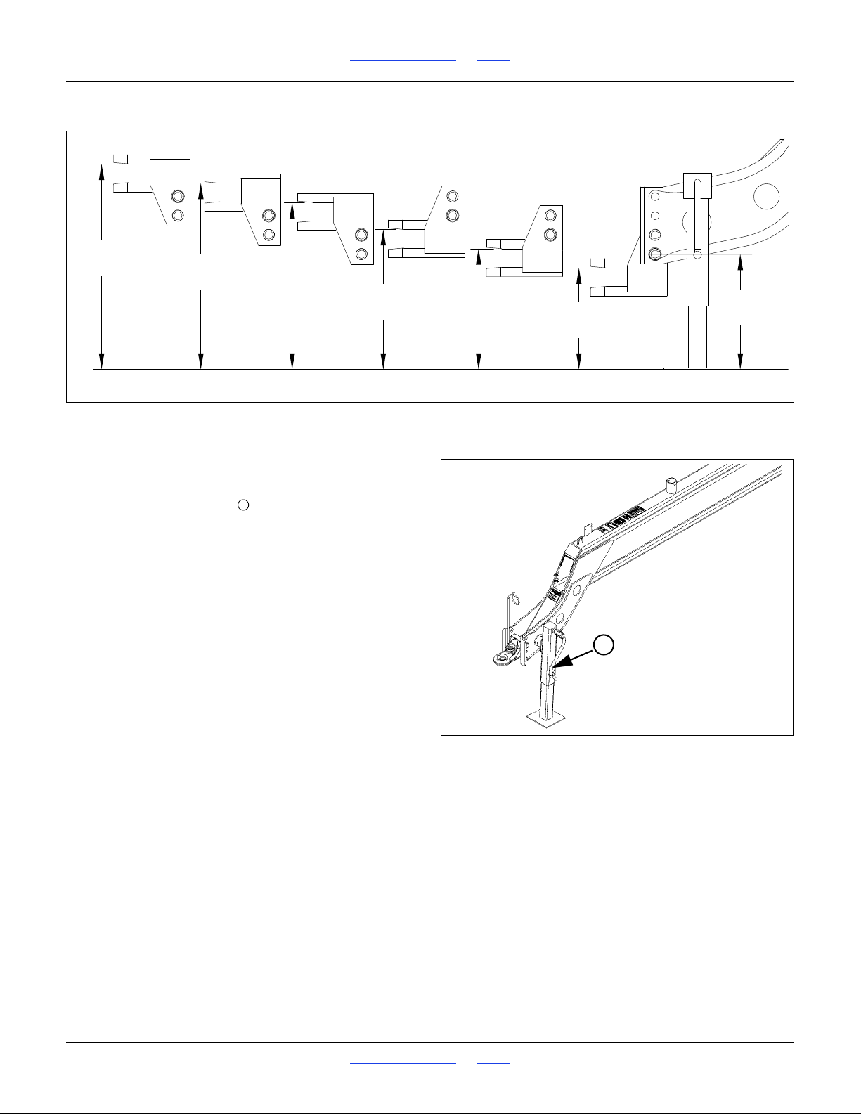
Refer to Figure 10
1. To adjust the drill hitch to match your tractor-drawbar
height, raise drill tongue so the lowest hitch hole is
18 inches off the ground.
NOTE:
When hitching drill to a different tractor, check for a
difference in drawbar heights. If heights are different,
readjust hitch height accordingly.
2017-10-26 Table of Contents Index 195-325M
Page 27
3S-5000/F/HD/HDF Table of Contents Index Preparation and Setup 23
32.0 inch
(81.3cm)
29.0 inch
(73.7cm)
26.0 inch
(66.0cm)
21.5 inch
(54.6cm)
18.5 inch
(47.0cm)
15.5 inch
(39.4cm)
18.0 inch
(45.7cm)
HITCH HEIGHTS AT VARIOUS POSITIONS CORRECT TONGUE HEIGHT
Figure 10
Hitch Heights
34232
Figure 11
Jack - S/N C1287L and below
34349
1
1
For drills with Serial Number C1287L and below
Refer to Figure 11
1. Mount the tongue jack on the side of the tongue.
Use the jack to raise the drill tongue.
2. Securely attach safety chain to an anchor on a
tractor capable of pulling the drill.
3. Store jack on top of tongue.
4. Plug drill electrical lead in tractor seven-pin
connector. If your tractor is not equipped with a
seven-pin connector, contact your dealer for
installation.
2017-10-26 Table of Contents Index 195-325M
Page 28
3S-5000/F/HD/HDF Table of Contents Index Preparation and Setup 24
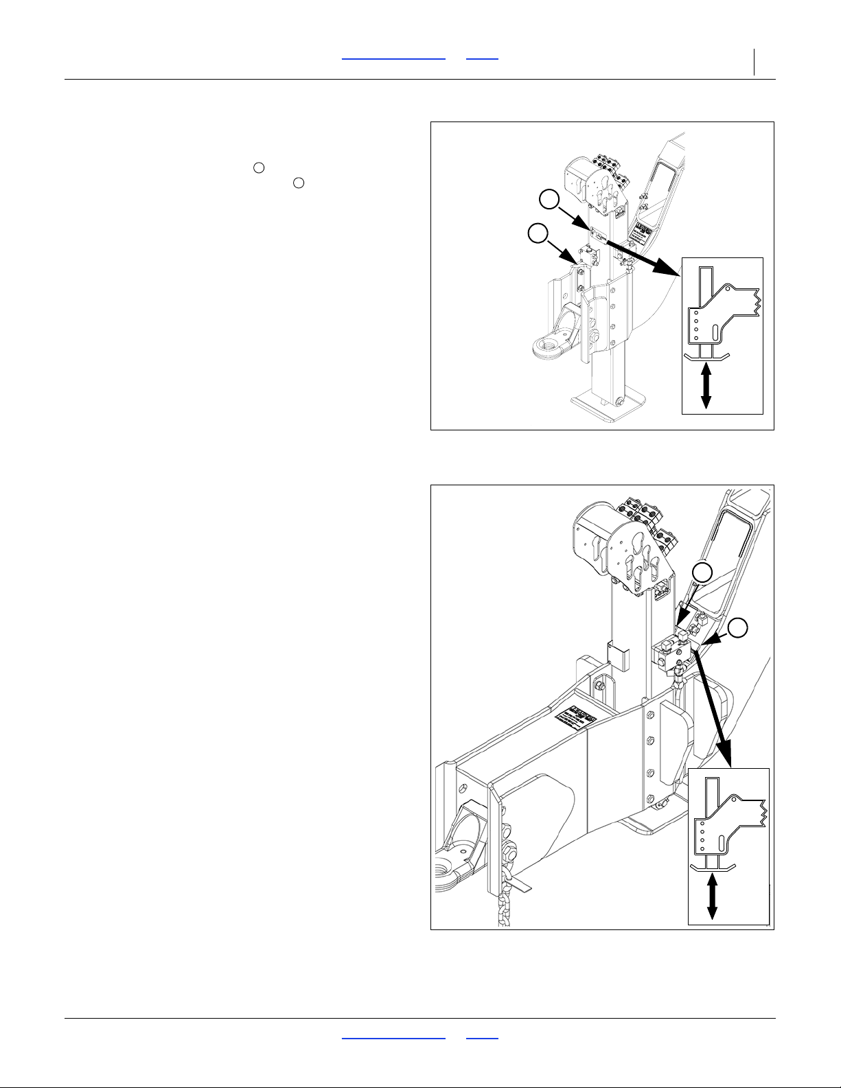
Figure 12
Jack - S/N C1288L to S/N C1295L
38568
2
3
2
3
Figure 13
Jack - S/N C1296L and above
38568
2
3
For drills with Serial Number C1288L and above
Refer to Figure 12 and Figure 13
1. Move the selector valve to the jack operating
position as shown on the decal . Use the tractor
hydraulics to raise or lower the drill tongue.
2. Securely attach safety chain to an anchor on a
tractor capable of pulling the drill.
3. Plug drill electrical lead in tractor seven-pin
connector. If your tractor is not equipped with a
seven-pin connector, contact your dealer for
installation.
2017-10-26 Table of Contents Index 195-325M
Page 29
3S-5000/F/HD/HDF Table of Contents Index Preparation and Setup 25
Figure 14
Color Coded Hose Handles
31733
Hydraulic Hose Hookup
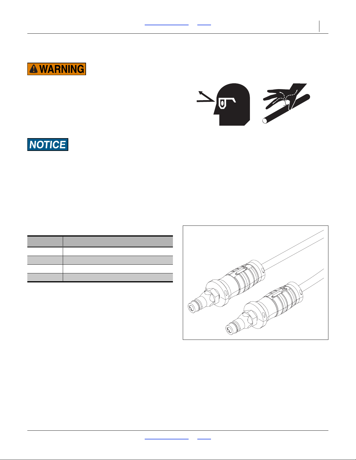
High Pressure Fluid Hazard:
Relieve pressure before disconnecting hydraulic lines.
Escaping fluid under pressure can have sufficient pressure to
penetrate the skin causing serious injury. Use a piece of paper
or cardboard, NOT BODY PARTS, to check for leaks. Wear
protective gloves and safety glasses or goggles when working
with hydraulic systems. If an accident occurs, seek immediate
medical attention from a physician familiar with this type of
injury.
To run dril l on tractors with open center hydrauli cs or on
tractors with fixed-displacement hydraulic pumps, you must
install a Great Plains kit, part number 194-143A. If you are
not familiar with your tractor hydraulics, cons ult your tractor
dealer.
Refer to Figure 14
Great Plains hydraulic hoses have color coded handle
grips to help you hookup hoses to your tractor outlets.
Hoses that go to the same remote valve are marked with
the same color.
Current Style Color Coded Hose Handles
Color Hydraulic Function
Red Opener Lift Cylinders
Blue Transport Lift Cylinders
Gray Fold Cylinders / Hydraulic Jack
Green Marker Cylinders
To distinguish hoses on the same hydraulic circuit, refer
to the symbol molded into the handle grip. Hoses with an
extended-cylinder symbol feed cylinder base ends.
Hoses with a retracted-cylinder symbol feed cylinder rod
ends.
1. Connect opener-lift hoses to circuit designated for
hydraulic-motor control.
2. Connect transport-lift hoses to tractor remote valve.
3. Connect fold hoses to tractor remote valve.
NOTE:
If your tractor has only two remote valves, you must
install a double-selector valve to combine the
transport-lift and opener-lift circuits. See “Two Outlet
Hydraulic Kit” on page 94.
2017-10-26 Table of Contents Index 195-325M
Page 30
3S-5000/F/HD/HDF Table of Contents Index Operating Instructions 26
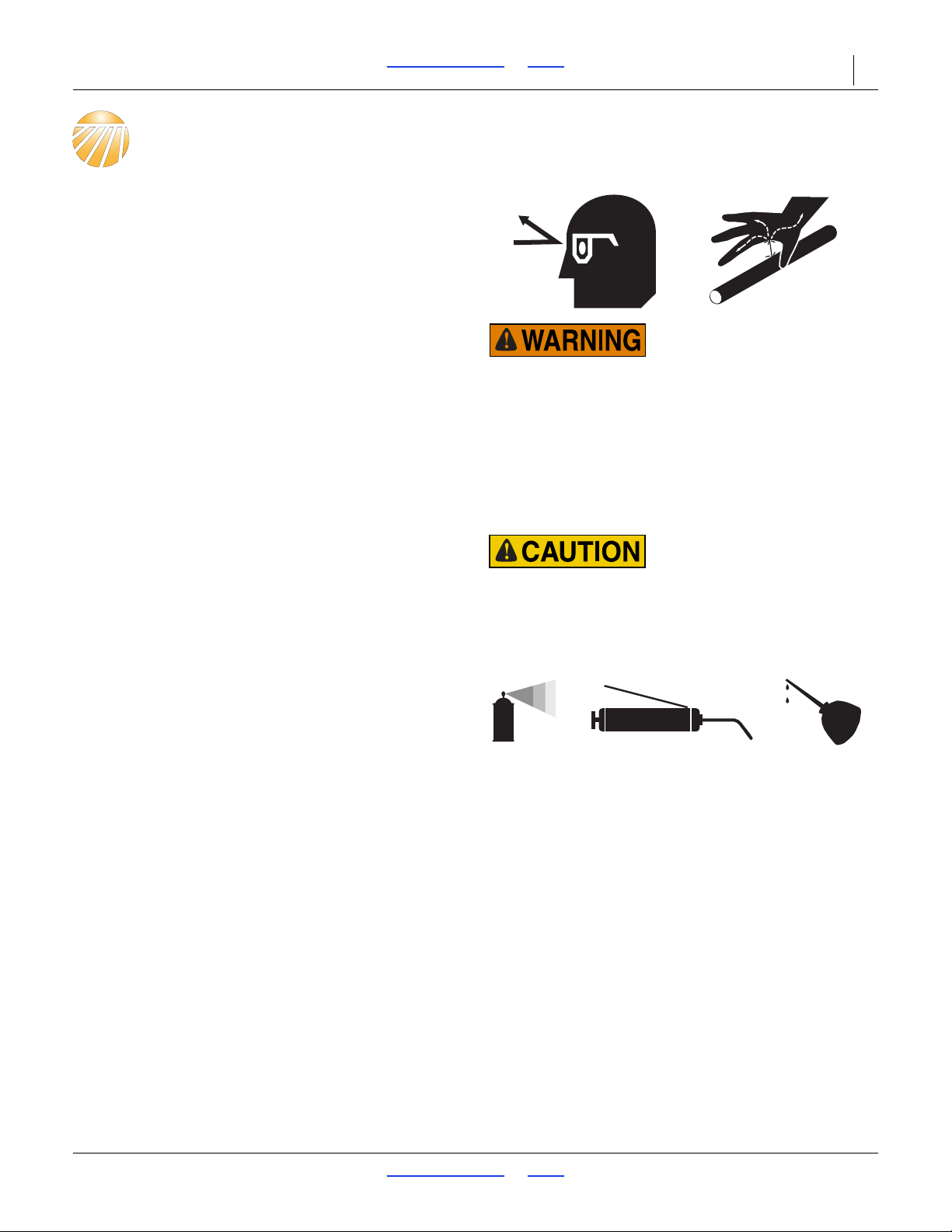
High Pressure Fluid Hazard:
Relieve pressure before disconnecting hydraulic lines. Use a
piece of paper or cardboard, NOT BODY PARTS, to check for
leaks. Wear protective gloves and safety glasses or goggles
when working with hydraulic systems. Escaping fluid under
pressure can have sufficient pressure to penetrate the skin
causing serious injury. If an accident occurs, seek immediate
medical assistance from a physician familiar with this type of
injury.
Spill hazard/Tank damage risk:
Periodically check the tension of the straps for the fertilizer
tank. Strap tension will change as outside air temperature
changes. Adjust tension as necessary to prevent personal
injury or damage to the fertilizer tank.
Operating Instructions
This section covers general operating procedures.
Experience, machine familiarity, and the following
information will lead to efficient operation and good
working habits. Always operate farm machinery with
safety in mind.
Pre-Start Checklist
Perform the following steps before transporting the
3S-5000/F/HD/HDF Drill to the field.
Carefully read “Important Safety Information” on
page 1.
Lubricate drill as indicated under “Lubrication” on
page 83.
Check all tires for proper inflation. See
“Specifications and Capacities” on page 96.
Check all bolts, pins, and fasteners. Torque as
shown in “Torque Values Chart” on page 109.
Check drill for worn or damaged parts. Repair or
replace parts before going to the field.
Check hydraulic hoses, fittings, and cylinders for
leaks. Repair or replace before going to the field.
Perform all beginning-of-season and daily service
items under “Maintenance” on page 72.
2017-10-26 Table of Contents Index 195-325M
Page 31
3S-5000/F/HD/HDF Table of Contents Index Operating Instructions 27
Figure 15
Jack - S/N C1288L to S/N C1295L
38568
1
2
1
2
Figure 16
Jack - S/N C1296L and above
38568
1
2
Folding
Crushing Hazard:
Bystanders could be crushed between the folding drill boxes
and the drill tongue. To avoid serious injury or death, keep all
bystanders well away during drill operation.
1. Park tractor and drill on level ground with tractor
transmission in park. Be aware of clearance needed
to fold drill.
2. Fold up markers.
Refer to Figure 15 and Figure 16
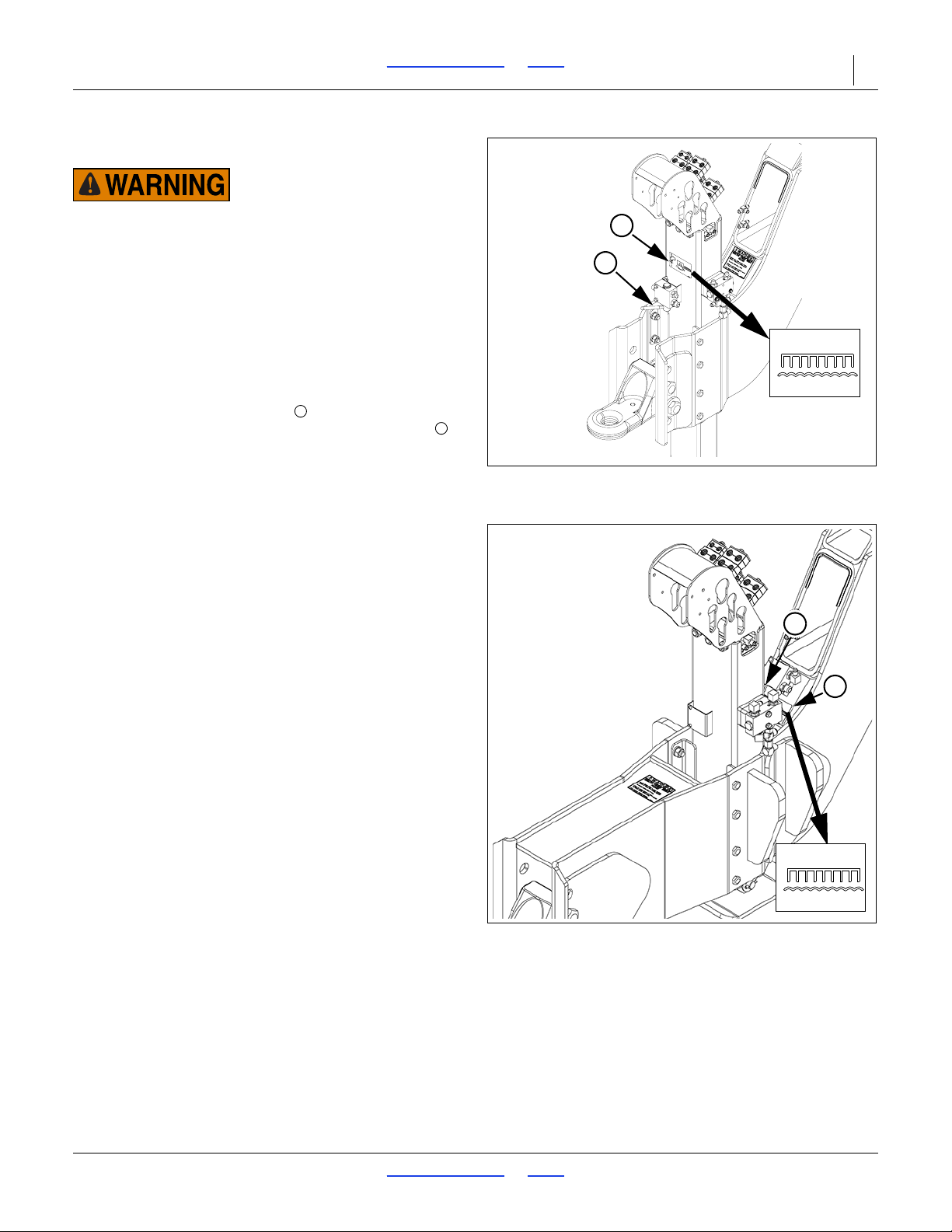
3. For drills with Serial Number C1288L and above:
Move the selector valve on the jack to the
folding/unfolding position as shown on the decal .
2017-10-26 Table of Contents Index 195-325M
Page 32
3S-5000/F/HD/HDF Table of Contents Index Operating Instructions 28
Figure 17
Opener Lock Up
34294
Figure 18
Transport Lift Cylinder Lock
34321
Figure 19
Front Box Lift Cylinder Lock
18959
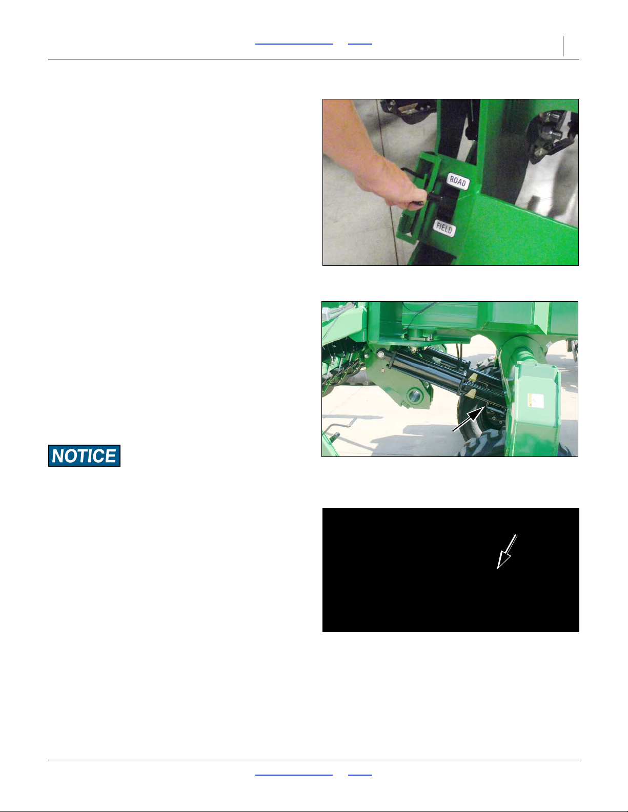
Refer to Figure 17
4. Position opener lock handles in road position and
completely raise openers.
NOTE:
The opener transport lock handles are spring loaded
and can be moved to ROAD position with openers u p
or down, but locks will only engage when openers are
completely raised. There are two locks on each drill
section (six total).
5. Make sure transport lift cylinders and front box lift
cylinder are completely retracted.
6. Slowly supply oil to rod end of fold circuit.
Completely fold wing frames until both wing gauge
wheels contact tongue tube.
7. Supply oil to transport lift circuit until transport lift
cylinders and front box lift cylinder are completely
extended and drill is completely raised.
Refer to Figure 18 and Figure 19
8. Rotate cylinder lock channels over rods on the two
transport lift cylinders and the front box lift cylinder.
The channels will remain in position when cylinders settle
against channels.
9. Allow transport lift cylinders to settle back against
lock channels.
10. Before transporting, check that hydraulic cylinders
are holding lock channels securely.
2017-10-26 Table of Contents Index 195-325M
Page 33
3S-5000/F/HD/HDF Table of Contents Index Operating Instructions 29
Figure 20
Jack - S/N C1288L to S/N C1295L
38568
1
2
1
2
Figure 21
Jack - S/N C1296L and above
38568
1
2
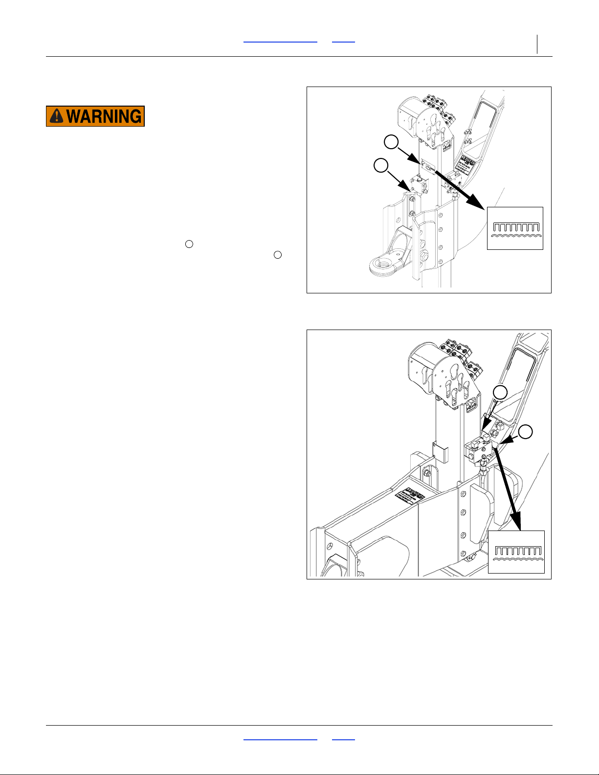
Unfolding
Crushing Hazard:
Bystanders could be crushed between the folding drill boxes
and the drill tongue. To avoid serious injury or death, keep all
bystanders well away during drill operation.
1. Park tractor and drill on level ground with tractor
transmission in park. Be aware of clearance needed
to unfold drill.
Refer to Figure 20 and Figure 21
2. For drills with Serial Number C1288L and above:
Move the selector valve on the jack to the
folding/unfolding position as shown on the decal .
2017-10-26 Table of Contents Index 195-325M
Page 34
3S-5000/F/HD/HDF Table of Contents Index Operating Instructions 30
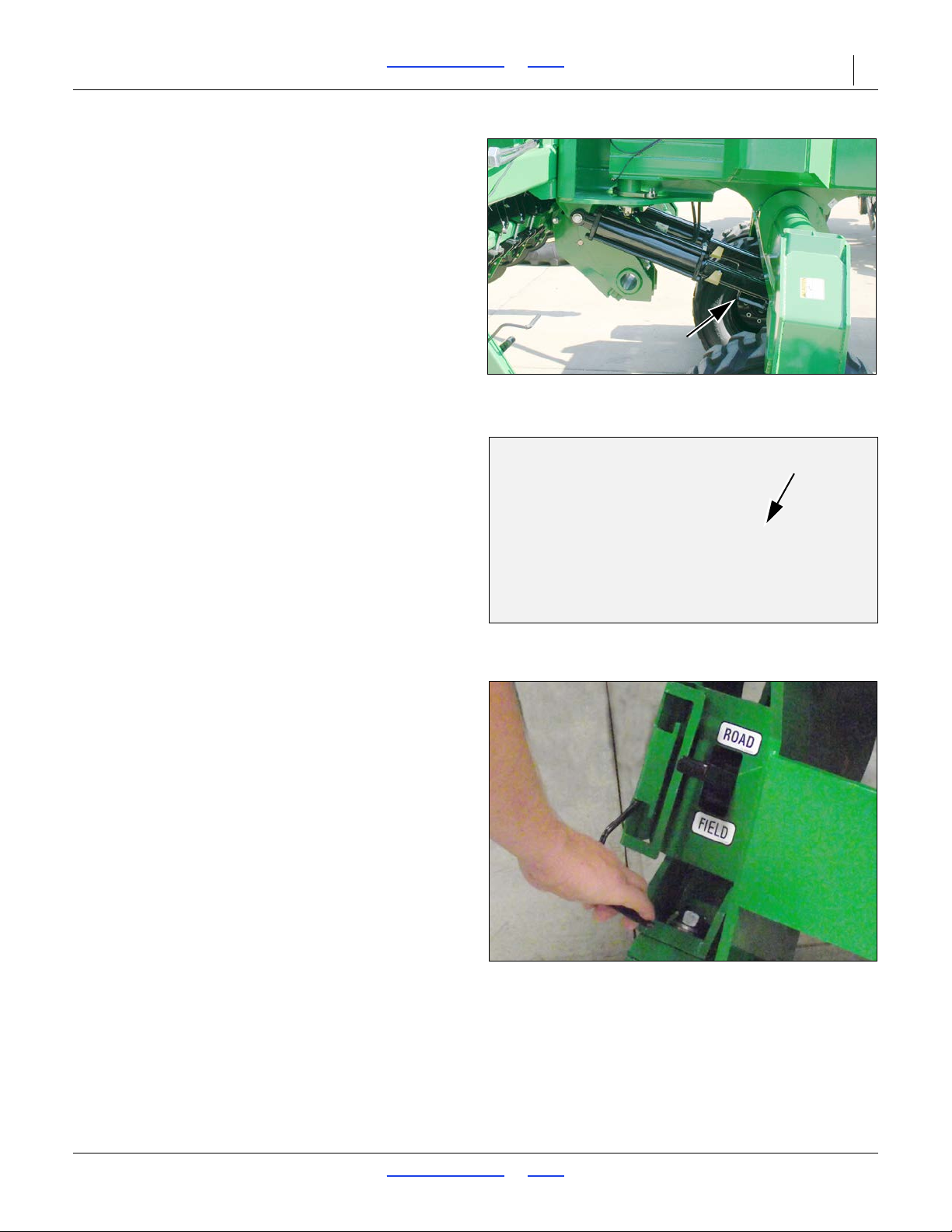
Figure 22
Transport Lift Cylinder Lock
34321
Figure 23
Front Box Lift Cylinder Lock
18959
Figure 24
Opener Unlock
34286
3. Supply oil to transport lift circuit until transport lift
cylinders and front box lift cylinder are completely
extended and drill is raised completely.
Refer to Figure 22 and Figure 23
4. Rotate cylinder lock channels off cylinder rods of
transport lift cylinders and front box lift cylinder.
5. Completely retract transport lift cylinders and front
box lift cylinder.
6. Slowly supply oil to base end of fold circuit. Unfold
wing frames by completely extending fold cylinders.
Refer to Figure 24
7. Position opener transport lock handles in FIELD
position.
8. Completely raise openers to allow opener transport
locks to disengage.
NOTE:
The opener transport lock handles are spring loaded
and can be moved to field position with openers up or
down, but locks will only disengage when op eners are
completely raised. There are two lock handles on
each drill section (6 total).
2017-10-26 Table of Contents Index 195-325M
Page 35
3S-5000/F/HD/HDF Table of Contents Index Operating Instructions 31
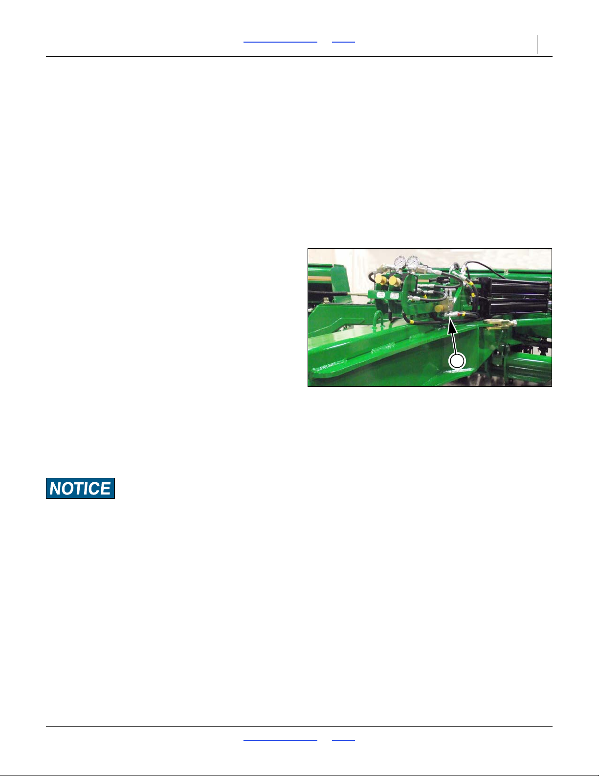
Figure 25
Bypass Valve
34296
1
Folding and Unfolding Quick Reference
To Fold Drill
1. Move selector valve on jack.
2. Fold markers.
3. Raise openers.
4. Fold drill.
5. Extend transport and front box lift cylinders.
6. Lock transport and front box lift cylinders.
Setting the Bypass Valve
Refer to Figure 25
A bypass valve is plumbed into the opener down
pressure circuit. Tractors with load-sensing,
closed-center hydraulics require this bypass valve to
protect the tractor hydraulic system.
If you are unsure what type of hydraulic system is on
your tractor, contact your tractor manufacturer.
Tractors with Open Center Hydraulics
Close bypass valve for no oil flow by turning knob on
valve clockwise completely. Always operate the drill with
the bypass valve closed.
Tractor s with Pressure Compensating Closed Ce nter
Hydraulics (PC Closed)
Close bypass valve for no oil flow by turning knob on
valve clockwise completely. Always operate the drill with
the bypass valve closed.
Tractors with Load Sensing Closed Center
Hydraulics (LS Closed) or Pressure Flow
Compensating (PFC) Systems
To Unfold Drill
1. Move selector valve on jack.
2. Completely extend transport and front box lift
cylinders.
3. Unlock transport and front box lift cylinders.
4. Retract transport and front box lift cylinders.
5. Unfold drill.
6. Lower openers.
Equipment Damage Risk:
Failure to use the bypass valve on load-sensing tractors may
cause major tractor damage.
1. Close bypass valve for no oil flow by turning knob on
valve clockwise completely.
2. With tractor at half throttle, adjust flow-control valve
on tractor so openers raise and lower at a
reasonable speed. Keep tractor at one-half throttle
for remaining steps.
NOTE:
The faster openers raise and lower, the greater
potential for oil heating, premature wear or tractor
damage.
3. Engage tractor hydraulics and lower openers. Lock
hydraulic lever on tractor for continuous operation.
2017-10-26 Table of Contents Index 195-325M
Page 36
3S-5000/F/HD/HDF Table of Contents Index Operating Instructions 32
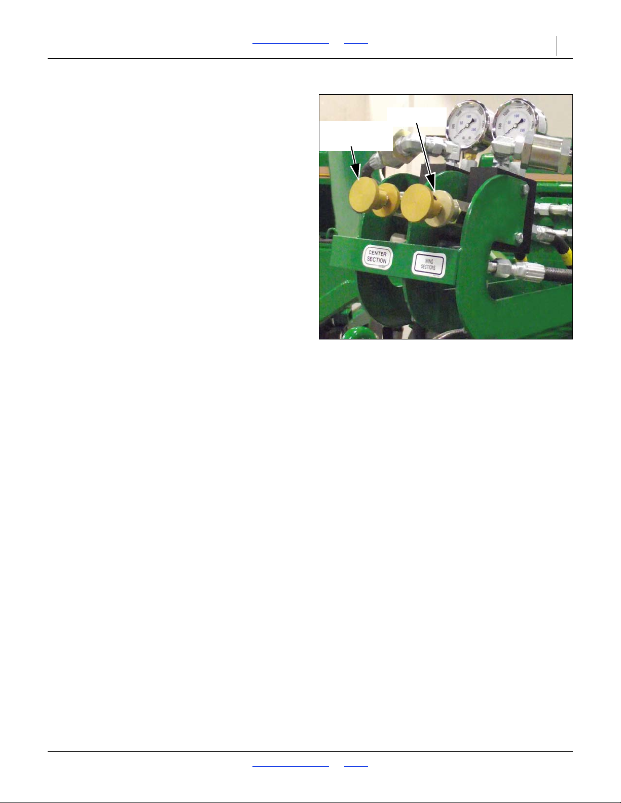
Figure 26
Opener Down Pressure Control
Valves
34293
Adjustment
Knob
Lock Disk
Refer to Figure 26
4. Adjust pressure-control valves on drill for opener
down pressure so gauges are at 1800 psi.
5. While watching gauges on drill, slowly turn knob on
bypass valve counterclockwise. Adjust bypass valve
just until needles on gauges begin to move down
from 1800 psi. Lock bypass valve at this setting.
(See also note below.)
6. Adjust pressure-control valves on drill to desired
opener down pressure as explained under
“Hydraulic Down Pressure All Openers” on
page 57.
NOTE:
The higher the bypass pressure, the greater the
potential for oil heating and premature tractor
damage. At the same time, for proper opener
operation the bypass valve must be set at least
300 psi above the opener down-pressure setting
when the tractor is at one-half throttle. Therefor e, you
should set the bypass valve as low as possible while
staying at least 300 psi above the opener down
pressure setting.
While 1800 psi is a good starting point for setting the
bypass valve, if you consistently operate the drill with low
opener down pressure you can set the bypass valve
below 1800 psi. If you consistently operate the drill with
very high opener down pressure, you may need a
bypass-valve setting above 1800 psi.
2017-10-26 Table of Contents Index 195-325M
Page 37

3S-5000/F/HD/HDF Table of Contents Index Operating Instructions 33
Opener Operation
The openers are raised and lowered on their own
hydraulic circuit. When used with an active hydraulic
system, constant hydraulic do wn pressure is placed on
openers for even soil penetration across the drill. To
operate openers with live hydraulic power, always
connect the opener-lift hoses to the circuit designated for
hydraulic-motor control.
To achieve proper opener flotation, the opener hydraulic
circuit must be powered by an active hydraulic system.
An active hydraulic system requires a tractor with
closed-center hydraulics or pressure-flow compensated
hydraulics powered by a variable displacement hydraulic
pump.
To run drill on tractors with open center hydraulics or on
tractors with fixed-displacement hydraulic pumps, you
must install a Great Plains kit, part number 194-143A.
Contact your Great Plains dealer for ordering
information.
If you are not familiar with your tractor’s hydraulics,
consult your tractor dealer.
For more information on opener adjustments, see
instructions beginning on page 57.
Crushing Hazard:
You will be seriously injured or killed if you are caught
between raising openers and drill frame. Always stop tractor
engine, set park bake, and remove key before adjusting or
servicing openers. Keep all bystanders well away during drill
operation.
High Pressure Fluid Hazard:
Escaping fluid under pressure can penetrate the skin causing
serious injury. Avoid the hazard by relieving pressure before
disconnecting hydraulic lines. Use a piece of paper or
cardboard, NOT BODY PARTS, to check for suspected leaks.
Wear protective gloves and safety glasses or goggles when
working with hydraulic systems. If an accident occurs, see a
doctor immediately. Any fluid injected into the skin must be
surgically removed within a few hours or gangrene may result.
2017-10-26 Table of Contents Index 195-325M
Page 38
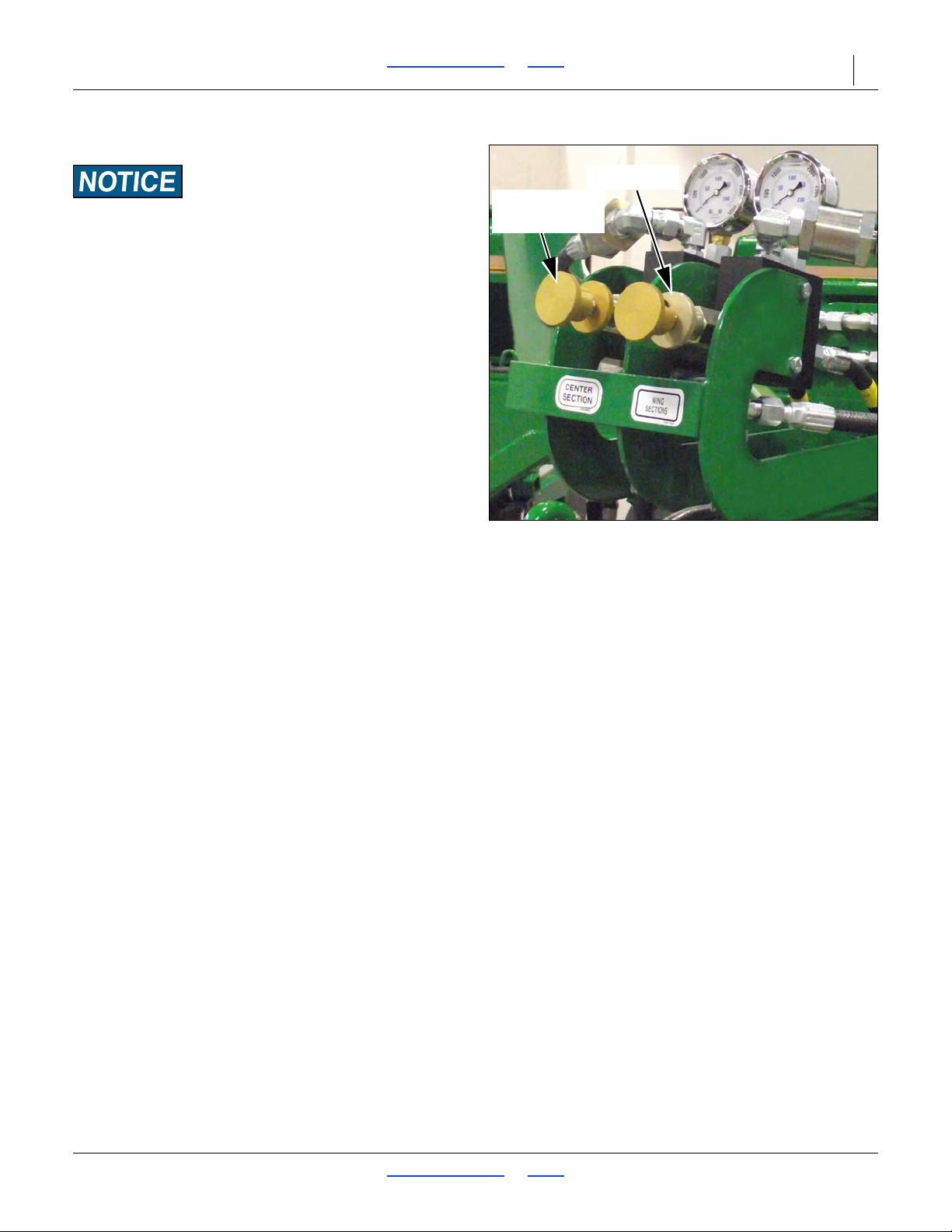
Figure 27
Pressure Control Valves
34293
Adjustment
Knob
Lock Disk
3S-5000/F/HD/HDF Table of Contents Index Operating Instructions 34
Active Hydraulic Systems
Equipment Damage Risk:
Tractors with load-sensing hydraulics must use the bypass
valve to operate the 3S-5000. Failure to use the bypass valve
can cause major tractor damage. Before adjusting opener
down pressure, set bypass valve as explained under “Setting
the Bypass Valve” on page 31.
1. Lock hydraulic lever forward during field operation
for constant hydraulic flow to openers.
John Deere tractors with Sound-Gard™ Body:
Use lever lock clip, John Deere part number R52667, to
lock lever forward. See your tractor dealer for clip
purchase and installation.
John Deere 7000 Series tractors:
Rotate valve detent selector to motor position to lock
lever in forward position.
John Deere 8000 Series tractors:
Set timer to continuous. Push lever forward until detent
clicks.
Case-IH Magnum tractors:
Lock lever forward in detent posit ion. You may need to
turn up detent pressure to its maximum setting. Do not
tie hydraulic lever past detent position with a strap. See
your tractor dealer for hydraulic-system details.
Other tractors:
Lock lever forward in detent posit ion. You may need to
turn up detent pressure to maximum or use a mechanical
detent holder to hold lever forward. See your tractor
dealer for proper means of providing constant flow to
openers.
Refer to Figure 27
2. With tractor hydraulic lever locked forward and
openers in field position, set down pressure with
adjustment knob. Watch pressure gauge and dial in
desired pressure on openers. There is one
pressure-control valve for openers on center section
and one for openers on wing sections of drill.
NOTE:
Rotate knob clockwise to increase pressure and
counterclockwise to decrease pressure.
3. Once pressure is set, lock each knob with lock disk.
4. In some typical applications, pressure on center
section is set slightly higher that the wings to account
for additional compaction from drill transport tires
and tractor tires. The recommended pressure range
for drilling is between 200 psi and 1600 psi.
For drills without markers: Setting opener down
pressure above 1600 psi. will raise drive wheels off
the ground when the seed box is empty causing
skips and poor seed metering.
For drills with markers: Setting opener down
pressure above 2300 psi. will raise drive wheels off
the ground when the seed box is empty causing
skips and poor seed metering.
5. For more information on adjusting hydraulic down
pressure, see “Hydraulic Down Pressure All
Openers” on page 57.
During operation always raise openers before turning.
Never back up or turn sharply with openers in the
ground. Doing so will plug openers and may damage
equipment.
2017-10-26 Table of Contents Index 195-325M
Page 39
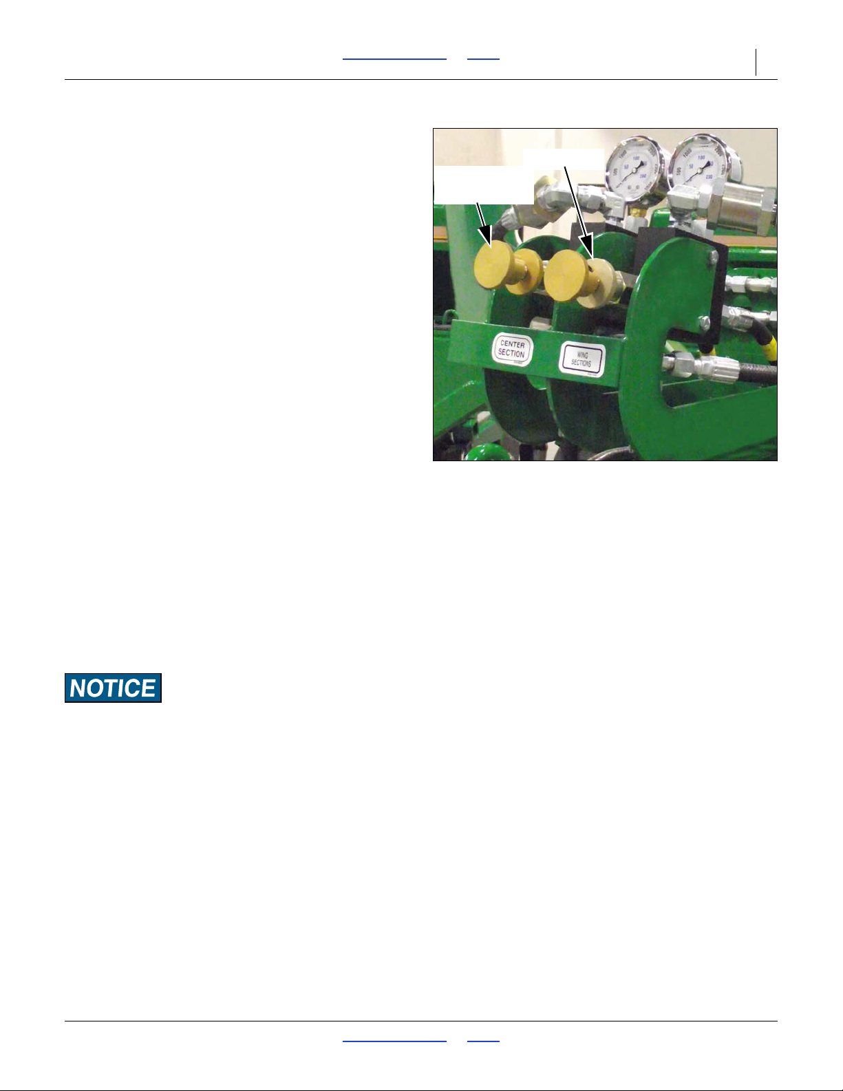
Figure 28
Pressure Control Valves
34293
Adjustment
Knob
Lock Disk
3S-5000/F/HD/HDF Table of Contents Index Operating Instructions 35
Priority Flow Hydraulic Systems
On some tractors with load-sensing hydraulics, circuit #1
is capable of taking nearly 100 percent of available
hydraulic flow. Operating the openers or markers on
circuit #1 will starve the other circuit, making one function
inoperable.
To operate markers and constant opener down pressure
at the same time, connect the openers to circuit #2 and
the markers to circuit #3.
Non-Active Hydraulic System
To run drill with open center hydraulics or
fixed-displacement hydraulic pumps requires a Great
Plains kit, part number 194-143A. After installing the kit,
refer to the following instructions for opener operation.
1. Lower opener frames by pushing forward on tractor
hydraulic lever. Lock lever temporarily in this position
while adjusting opener down pressure.
Refer to Figure 28
2. With tractor hydraulic lever locked forward, set down
pressure with adjustment knob. Watch pressure
gauge and dial in desired pressure on openers.
There is one pressure-control valve for openers on
center section and one for openers on wing sections
of drill.
NOTE:
Rotate knob clockwise to increase pressure and
counterclockwise to decrease pressure.
3. Once pressure is set, lock each knob with lock disk.
4. After opener down pressure is set, return tractor
hydraulic lever to neutral. This locks in the selected
pressure, and opener frames will remain fixed in this
position.
During operation:
• Each time openers are lowered, hold tractor remote
hydraulic lever forward for a few seconds to
recharge circuit, then return it to its neutral position.
The tractor and drill should be on level ground when
returning tractor lever to neutral.
• When approaching rough terrain where you need
Tractor Damage Risk:
Open-center tractors and tractors with fixed-displacement
pumps are not designed to provide a continuous supply of
pressurized oil to remote valves. Locking hydraulic lever
forward on these tractors can cause overheating of hydraulic
oil and tractor damage. After setting opener down pressure,
always return hydraulic lever to neutral.
NOTE:
On some tractors with very positive remote hydraulic
checks, a slight increase in the reading on the
pressure gauges may occur after tractor remote
lever is returned to neutral. This is caused by back
pressure on opener cylinders and should be ignored.
The net operating pressure on opener cylinders is
maintained at the pressure you selected while tractor
remote lever was held forwar d-not at the apparent ly
increased pressure. Reactivating tractor lever
forward will confirm this.
active hydraulics to maintain even opener
penetration, push tractor hydraulic lever forward
momentarily. As soon as you return to level ground,
return lever to neutral. Do not activate tractor
hydraulic lever for more than 20 seconds at a time,
once every 2 minutes. Always wait until tractor and
drill are on level ground before returning lever to
neutral. You can bump tractor hydraulic lever forward
any time on level ground to assure the preset
pressure is correctly locked in and to reset the
system.
• Always raise openers before turning. Never back up
or turn sharply with openers in the ground. Doing so
will plug openers and may damage equipment.
2017-10-26 Table of Contents Index 195-325M
Page 40
3S-5000/F/HD/HDF Table of Contents Index Operating Instructions 36
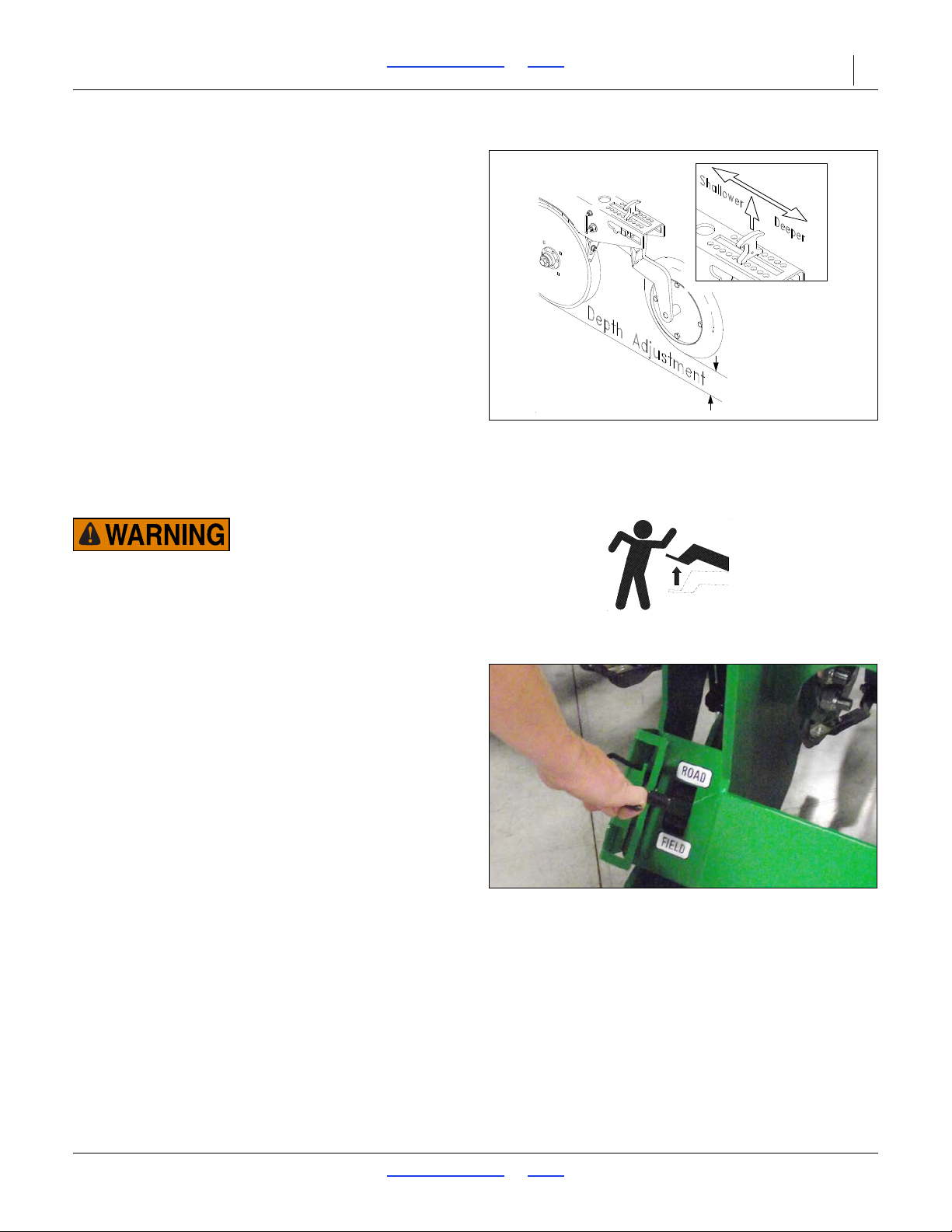
Figure 29
Press Wheel Adjustment
15659
Figure 30
Opener Lock Up
34294
Opener Depth
After opener pressure is set on an active or non-active
hydraulic system, set opener seeding depth by adjusting
press wheel height.
Refer to Figure 29
1. To adjust, raise openers slightly.
2. Lift and slide T-handles on top of openers.
• For shallower seeding, slide
T-handles toward drill.
• For deeper seeding, slide T-handles
away from drill.
3. Adjust all press wheels to the same height.
Raising and Lowering Openers
Negative Weight: Raising openers on unfolded, unhitched drill
will cause drill tongue to rise suddenly, which could cause
serious injury or death. Be certain that drill is hitched securely
to your tractor draw bar and the safety chain is securely
attached to tractor before raising openers and unfolding drill.
Opener sub-frames are on a dedicated hydraulic circuit.
Openers raise and lower independently of the drill frame
(which is raised and lowered by the transport lift circuit).
When lowered, the opener circuit can use live hydraulic
power to regulate down pressure. To operate with live
hydraulic power, connect the opener lift circuit to the #1
remote hydraulic circuit or the circuit designed for
HYDRAULIC MOTOR control. On many CLOSED
CENTER or PRESSURE/FLOW COMPENSATED
tractors the #1 circuit is the circuit designed to supply live
hydraulic power to remote locations.
On the standard 3S-5000/F/HD/HDF drill, the openers
raise and lower as a group, from a tractor cab lever . If the
Point Row Option is installed, each section can raise and
lower independently, using switches on the point row
control module in the tractor cab.
If the Two Outlet conversion kit is installed, a selector
valve near the hitch must be operated to switch between
Opener Lift and Transport Lift. During field operations,
this valve is in the Opener Lift position.
2017-10-26 Table of Contents Index 195-325M
Page 41
3S-5000/F/HD/HDF Table of Contents Index Operating Instructions 37
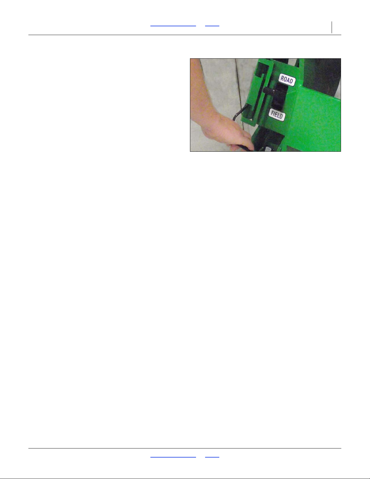
Figure 31
Opener Unlock
34286
Opener Lock Up
The openers must be locked up for transporting or for
working under the drill.
NOTE:
Opener transport lock handles can be moved with
openers up or down, but transport locks will only
engage after openers are raised completely and
disengage after openers are lowered completely.
There are two lock handles on each drill section.
Lock Up Openers
Refer to Figure 30
1. Position opener transport handles in ROAD position.
2. Raise openers completely.
Unlock Openers
Refer to Figure 31
1. Position opener transport lock handles in FIELD
position.
2. Raise openers completely.
2017-10-26 Table of Contents Index 195-325M
Page 42
3S-5000/F/HD/HDF Table of Contents Index Operating Instructions 38
Loading Main Seed Box
1. Check that all meter doors are positioned for the
seed size, and not set for clean-out. See “Position
Seed Cup Doors” on page 52. If loading prior to
transport, set them to position 1 (smallest seed).
2. Install or remove optional seed plu gs as desired for
the row spacing planned. See “Seed Cup Plugs
(Main Box)” on page 92. If loading prior to transport,
and calibration has not yet been done, set Seed
Rate Handle to 0. At 0, and with the doors at 1, no
seed can leak during transport.
3. If loading prior to transport, and calibration has not
yet been done, set Seed Rate Handles to 0. At 0,
and with the doors at 1, no seed can leak during
transport.
4. On fertilizer-capable drill models:
5. Take all necessary materials safety precautions if the
seed is treated.
6. Load material into box. Make sure material is loaded
or spread evenly across all partitions. Use tool or
gloved hand. Do not over fill boxes.
7. To reduce wea r, remove main shaft drive chains for
small seed boxes.
Loading Small Seeds Box
1. If loading prior to transport, and calibration has not
yet been done, set Seed Rate Handles to 0. At 0, no
seed can leak during transport.
2. Take all necessary materials safety precautions if the
seed is treated.
3. Load material into box. Make sure material is loaded
or spread evenly across all partitions. Use tool or
gloved hand. Do not over fill boxes.
4. To reduce wea r, remove main shaft drive chains for
main seed boxes.
• Check that the divider flap is set as desired (separate
compartments, or all-seed). See “Loading Fertilizer
Compartment” on page 39.
• If seeding only from the forward (seed) compartment,
flip the top spill flap back to prevent seed from
entering the fertilizer compartment. See “Loading
Fertilizer Compartment” on page 39.
Figure 32
Fill Decal
858-070C
Figure 33
Fill Decal on Bottom of Box Lid
68472
Loading Materials
The drill must be hitched for seed loading. Seed may be
loaded in the field or prior to transport.
Fully loaded with dense seed, the drill can weigh an
additional 9507 pounds (4312 kg). Include this weight
when checking tractor capability.
The mainframe may be raised or lowered. Lowered
places the walkboards closer to the ground, reducing
effort when manually loading bagged seed. If equipped
with ladders, swing them down.
Load slightly more material than needed, because
consumption rates can vary between compartments
even though the furrow rates are identical.
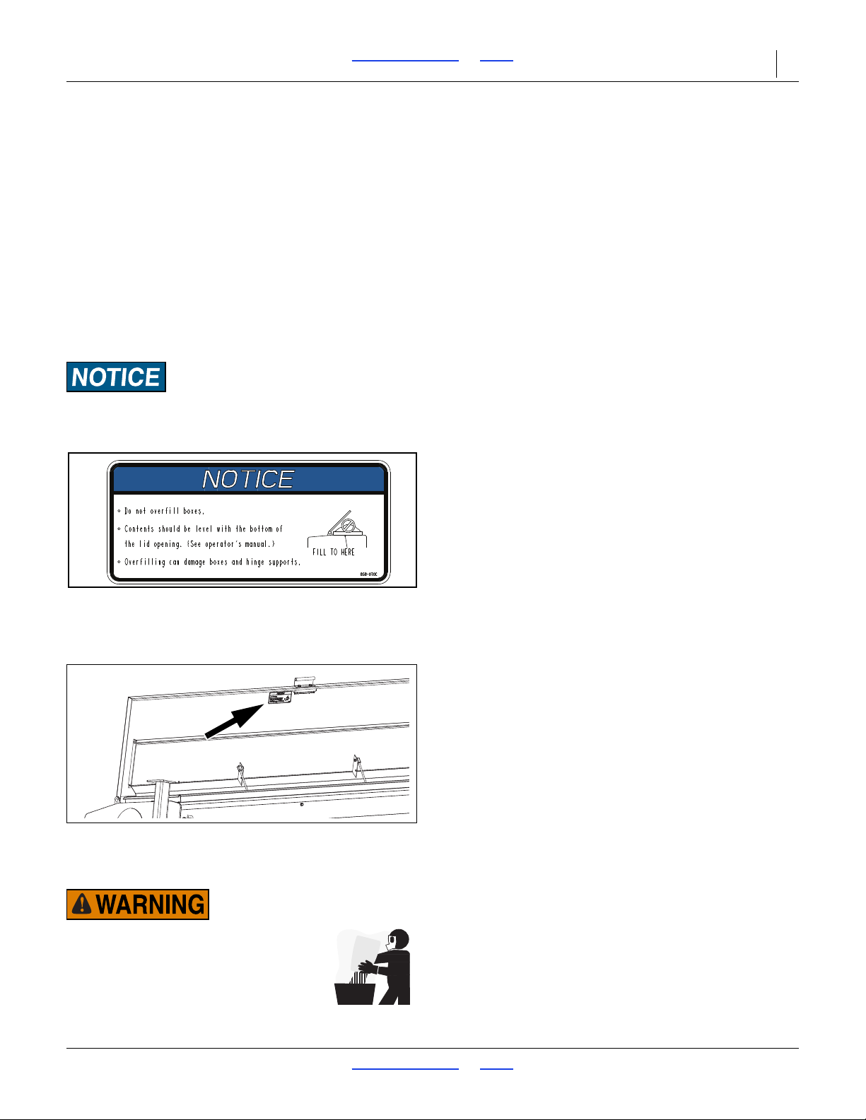
Do not overfill boxes. Contents should be level with the bottom
of the lid opening. Overfilling can damage boxes and hin ge
supports.
Possible Agricultural Chemicals Hazards:
Take all necessary materials safety
precautions when loading dusty seed,
treated seed or fertilizer.
2017-10-26 Table of Contents Index 195-325M
Page 43
3S-5000/F/HD/HDF Table of Contents Index Operating Instructions 39
1
Figure 34
Latch for Fertilizer Clean-out Door
16383
1
1
Figure 35
Seed/Fertilizer Flap Closed
16383
1
1
Figure 36
Spill Flap
16375
1
Loading Fertilizer Compartment
Load fertilizer after transport if possible. Some spillage
can occur through meters during transport, even with the
drive system disengaged.
Possible Agricultural Chemicals Hazards:
Take all necessary materials safety
precautions when loading dusty seed,
treated seed or fertilizer.
Refer to Figure 37
1. Clean any seed or debris from fertilizer
compartment. Close and latch the clean-out door.
Make sure all door latches are engaged before
loading fertilizer compartment.
Refer to Figure 33
2. Close the seed/fertilizer flap so seed and fertilizer
cannot pass between compartments.
Flap flips forward to block passage. The flap top
edge is secured to the dividers. Rotate the bent
clips to engage the edge of the flap, and tighten the
knobs .
Refer to Figure 34
3. Open spill flap over fertilizer compartment and
swivel back until it rests against open drill-box lid.
The spill flap serves as a spill guard to keep fertilizer
out of the seed compartment.
4. Fill fertilizer compartment. Make sure material is
loaded or spread evenly across all partitions. Use
tool or gloved hand. Do not overfill boxes.
5. To reduce wea r, remove main drive shaft chains for
main seed boxes.
2017-10-26 Table of Contents Index 195-325M
Page 44
3S-5000/F/HD/HDF Table of Contents Index Operating Instructions 40
Figure 37
Clean-Out Door Latched
34320
1
Figure 38
Divider Door
16383
1
1
1
2
3
123
Figure 39
Divider Door Secured
16380
2
4
2
4
Fertilizer Box Operation
The 3S-5000/F/HD/HDF is equipped with a fertilizer
compartment so you can plant seed and apply fertilizer in
the same field pass. Use only dry, granular fertilizer in
the fertilizer box.
1. Clean any seed or debris from fertilizer
compartment. Close and latch the clean-out door.
Make sure all door latches are engaged before
loading fertilizer compartment.
2. Adjust seed and fertilizer compartments to desired
capacity. The 3S-4000 is equipped with standard
dividers that partition drill boxes into 60 percent seed
and 40 percent fertilizer. If your drill is outfitted with
optional offset dividers, you can change the
seed-to-fertilizer ratio.
3. Calibrate fertilizer-application rate as explained in
the Seed Rate manual 195-325B.
Using Fertilizer Compartment
Refer to “Loading Materials” on page 38 and see
“Loading Fertilizer Compartment” on page 39.
Seeding with Both Compartments
1. Clean out boxes as explained under “Materials
Clean-Out” on page 80.
Refer to Figure 38
2. Open divider door between seed and fertilizer
compartments. To open door, loosen knobs .
Loosen knobs until bent clips can be turned off door.
3. When all bent clips have been turned, lift vinyl dew
shield (not shown) and flip the flap backward over
fertilizer-tray openings .
Refer to Figure 39
4. With seed/fertilizer flap covering fertilizer
openings, lower vinyl dew shield to hold flap over
fertilizer openings and away from divider.
5. To avoid unnecessary wear, remove fertilizer drive
chains.
2017-10-26 Table of Contents Index 195-325M
Page 45

3S-5000/F/HD/HDF Table of Contents Index Operating Instructions 41
2017-10-26 Table of Contents Index 195-325M
Page 46
3S-5000/F/HD/HDF Table of Contents Index Operating Instructions 42
Figure 40
3S-5000L Liquid Fertilizer System
36413
R
C
L
L15
L17
L18
L19
L22
L21
L23
L24
L26
L33
L30
L28
L27
L32
L29
L31
L12
L14
L13
L20
L25
U
D
F
B
L
R
L11
L16
L34
Liquid Fertilizer System (Option)
2017-10-26 Table of Contents Index 195-325M
Page 47

3S-5000/F/HD/HDF Table of Contents Index Operating Instructions 43
L11
L33
L19
L27
L28
L29
Liquid Fertilizer System Elements
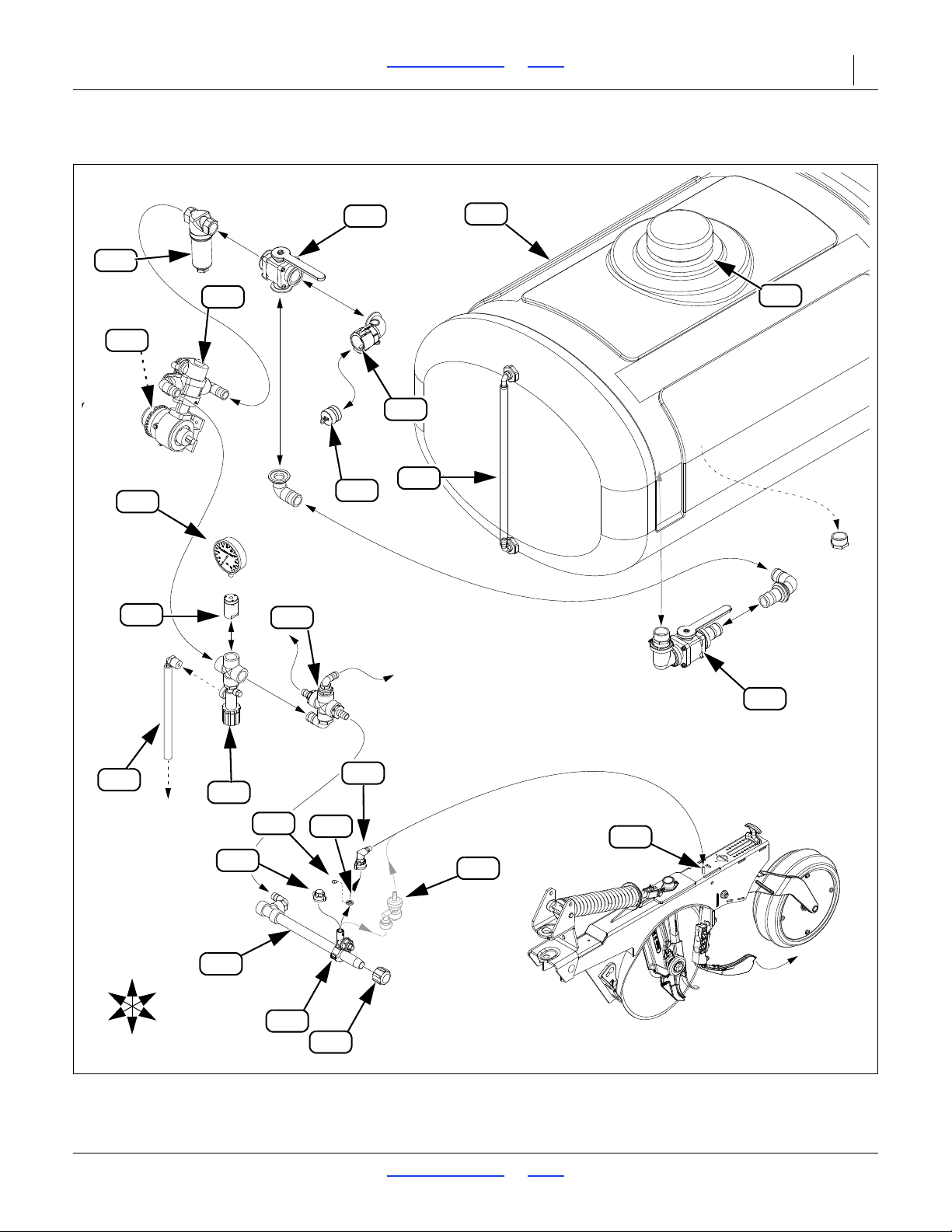
Refer to Figure 40 on page 42
Callout numbers through are consistent
throughout this manual and refer only to liquid fertilizer
system components.
L23. Relief valve
This valve sets the boom pressure (typically 65 psi)
above which the pump and nozzles will be protected
against over-pressure.
L11. Inlet cap
Leave this captive cap in the inlet except when loading
and unloading material. See “Loading Liquid Fertilizer”
on page 44.
L12. Supply tank
This tank holds 400 gallons (1514 liters) of pre-mixed
liquid fertilizer.
L13. Tank sight gauge
Provides visible indication of remaining material in the
tank.
L14. Tank vent/cap
For tank inspection, loading and wash-out, remove the
entire tank cap, or just the center section.
L15. Tank supply valve
Open for application or boom flush. Keep closed for
material loading, unloading and transport.
L16. Strainer inlet valve
(Quick-Fill) Normally left open. Close for strainer
cleaning or mesh replacement.
L17. Strainer
Prevents large particles from damage the pump or
clogging orifice plates and nozzles.
L18. CDS-John Blue
®
pump
The pump is driven by the ground drive wheel at a rate
determined by the range sprocket and adjuster
setting.
L19. Pump rate adjuster
This dial (on pump face away from page) provides fine
adjustment of pump rate. A tool is provided on the drive
assembly.
L20. Manifold
A tee and a cross divide the pump output for left and right
boom, pressure gauge and relief valve.
L24. Over-pressure dump line
If boom pressure exceeds the setting of the relief valve,
excess material is sent to the dump line and deposited
on the ground.
L25. Boom
There are separate boom lines for each section,
interconnected at the manifold tee.
L26. Nozzle body
Booms are provisioned with the maximum number of
nozzle bodies (row count) that the frame width supports.
Nozzles not in use are capped at the factory.
L27. Orifice plate
Standard nozzles regulate pressure at each row, and
balance pressure across the boom, by use of orifice
plates. Three standard sizes are supplied.
L28. Orifice gasket
The orifice plate is secured inside this gasket.
L29. Nozzle
The standard nozzle holds the orifice gasket in place.
L30. VeriFlow nozzle (op tion)
Replaces , and . Using this alternate nozzle
eliminates orifice plate changes over a wide range of
rates.
L31. Delivery tubing
Fertilizer is delivered to the Keeton
®
firmer.
L32. Unused tap nozzle cap
Additional caps are available for operations with
alternate row spacings.
L33. Boom cap
Remove for boom flush.
L34. Quick-fill
Open for quick filling.
L21. Gauge protector
Transmits boom pressure to the gauge, but prevents
caustic fertilizer from reaching the gauge.
L22. Pressure gauge
When applying material, this gauge displays the boom
pressure.
2017-10-26 Table of Contents Index 195-325M
Page 48
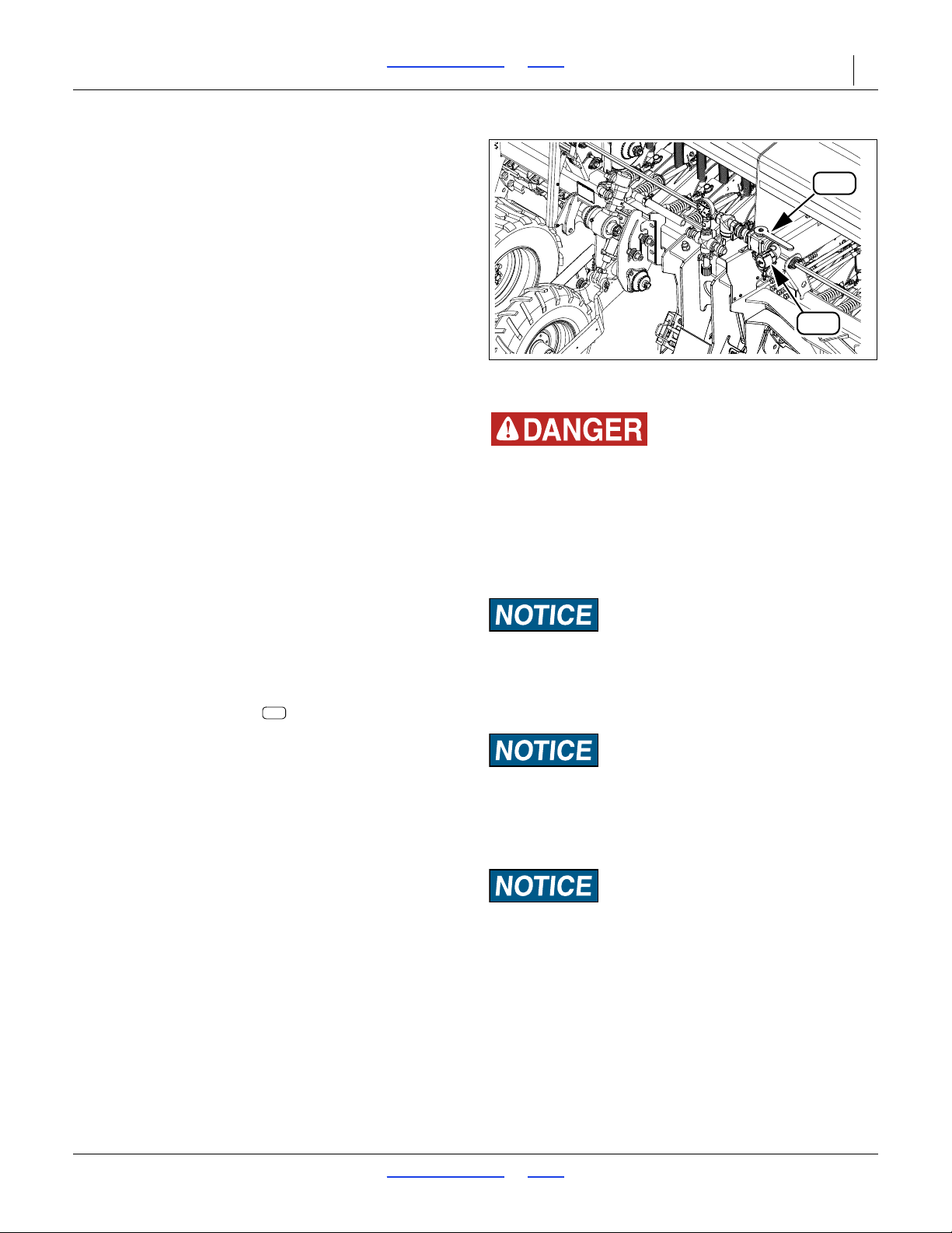
3S-5000/F/HD/HDF Table of Contents Index Operating Instructions 44
L16
L34
Agricultural Chemical Hazard:
Avoid contact with skin or eyes. Wear proper protective
equipment as required by chemical manufacturer. Avoid
prolonged breathing of chemical fumes. Wear respirator as
requir ed by chemical manufacturer. Some chemicals will cause
serious burns, lung damage, and death. Seek medical
assistance immediately if accident occurs. Know what to do in
case of accident.
Equipment Damage Risk:
Do not run the pump when dry. Remove the final pump drive
chain if not applying fertilize r. Air rapidly corrodes the pump.
When not pumping, fill the pump with clean water or RV
antifreeze.
Equipment Damage and Plugging Risks:
Use only materials compatible with polyethylene and
polypropylene. Use only pre-mixed liquid fertilizer. The system
is not designed for dry fertilizer mixes. Granular fertilizer may
damage the pump and plug orifices.
Equipment Damage Risk:
Do not leave fertilizer standing. Load late. Pump it all. Clean
out the system. Fertilizer is usually extremely caustic, and can
damage the piston pump if left standing. Also protect the pump
from air. See “Liquid Fertilizer Clean-Out” on page 81.
NOTE:
It is not possible to use the drill pump to load
material, as it only pumps when the drill is in motion
and is only plumbed to pump to the boom. If the
fertilizer source has no pump, it needs to be elevated
above the tank for gravity fill.
Figure 41
Quick-Fill Inlet
36423
L34
Loading Liquid Fertilizer
If fertilizer will not be applied, disengage the driveshaft
by pulling the drive lock out roll pin and twist it
90 degrees (located on the sprocket on the right side of
the drive wheel).
System Inspection
1. Wear protective equipment suitabl e for the material
presently in or previously dispensed from the tank(s).
2. Remove the lid on the tank and inspect for:
- residual fertilizer incompatible with next use
- contaminants
- debris that might clog filters
- trapped animals, lost tools, etc.
3. If it is necessary to flush the tank, or remove debris
too large to flush, see “Tank Clean-Out” on page 81.
4. Re-secure the lid.
5. At first use each season, and after extended use,
check the strainer mounted under the pump. Perform
any cleaning before loading fertilizer.
6. The standard screen size is 80 (Blue). Some orifice
selections (step 3) require changing th e str ain er.
Tank Loading
Refer to Figure 41
Review the information below before commencing steps.
• Load chemicals immediately prior to use. Material
loaded too early may sediment or stratify, resulting in
uneven application or system plugging.
• The tank is designed to be loaded using the 2-inch
cam-lock quick-fill inlet , located at the right front
of the implement. If for any reason you cannot use
that inlet, you can also load material via a ladder and
tank top hatch. The lid is threaded and unscrews.
• Determine how to monitor tank fill level. If the day is
bright, or loading at night with a bright light available,
it is possible to see the fluid level through the
semi-translucent tank walls. Otherwise, it is
necessary to have an observer monitor through the
tank hatch.
• Be familiar with the location of plumbing valves.
Common tasks require setting as many as five
valves.
1. Consult the Seed and Fertilizer Rate manual
(195-325B) for rate setting details.
2. Set the Fertilizer drive sprockets and piston pump
rate adjuster per the Rate charts.
3. Install the recommended size orifice plate at each
active drop line.
2017-10-26 Table of Contents Index 195-325M
Page 49

3S-5000/F/HD/HDF Table of Contents Index Operating Instructions 45
L16
L34
L15
L34
L16
L16
L15
L34
L16
L34
L15
L15
L15
L34
Quick-Fill Fertilizer Loading
If loading via tank top hatch, see “Hatch Fertilizer
Loading” (right column).
1. Set the quick-fill shutoff valve to closed (1a):
a. Handle to front: Closed: no flow at inlet
b. Handle to drill left: Fill: inlet open
2. Set selector valve to Quick-Fill (2a):
a. Handle arrow to drill left/front:
tank-to-quick-fill path open
b. Handle arrow to front/drill right:
valve closed: no flow at valve
c. Handle arrow to drill left/rear:
tank-to-pump path open
3. Set tank discharge valve to Operate (3a):
a. Handle arrow left: Operate (tank fill or pump)
b. Handle perpendicular to piping:
valve closed: no flow to or from tank
c. Handle arrow drill right:
clean-out: tank open to drain
4. Connect fertilizer supply to Quick-Fill inlet .
5. Open supply valve (if any) and check for leaks.
6. Alert observer to monitor tank fill level.
NOTE:
Although the lid is commonly removed to monitor fill
level, it is not necessary to remove it for filling. The
lid is vented, preventing back-pressure at normal fill
and application rates.
7. Start source pump (if any).
8. Open Quick-Fill inlet valve .
9. When tank reaches desired fill level,
stop source pump (if any),
close source valve (if any) and
close inlet shut-off .
10. Disconnect supply line at Quick-Fill.
11. Close any tank lid removed.
12. If loading fertilizer prior to transport, set tank
discharge valve to closed (3b). This keeps any
sedimentation out of the lines.
13. Set the selector valve to Pump (2c).
Fertilizer loading is complete.
Hatch Fertilizer Loading
If loading materials via Quick-Fill, see “Quick-Fill
Fertilizer Loading” instructions (left column).
Refer to Figure 41
1. Set the quick-fill shutoff valve to closed (1a):
a. Handle to front: Closed: no flow at inlet
b. Handle to drill left: Fill: inlet open
2. Set selector valve to Quick-Fill (2a):
a. Handle arrow to drill left/front:
tank-to-quick-fill path open
b. Handle arrow to front/drill right:
valve closed: no flow at valve
c. Handle arrow to drill left/rear:
tank-to-pump path open
3. For field loading, set tank discharge valve to
Operate (3a):
a. Handle pointer left: Operate (tank fill or pump)
b. Handle perpendicular to piping:
valve closed: no flow to or from tank
c. Handle arrow drill right:
clean-out: tank open to drain
For pre-transport loading, set tank discharge
valve to closed (3b). This keeps any
sedimentation out of the lines.
4. Remove lid on tank to load.
5. Route supply line into tank.
6. Commence fertilizer flow.
7. When tank reaches desired fill level,
stop source supply.
8. Close the tank lid.
9. If loading fertilizer prior to transport, set the tank
discharge valve to closed (3b). This keeps any
sedimentation out of the lines.
10. Set the selector valve to Pump (2c).
Fertilizer loading is complete.
2017-10-26 Table of Contents Index 195-325M
Page 50
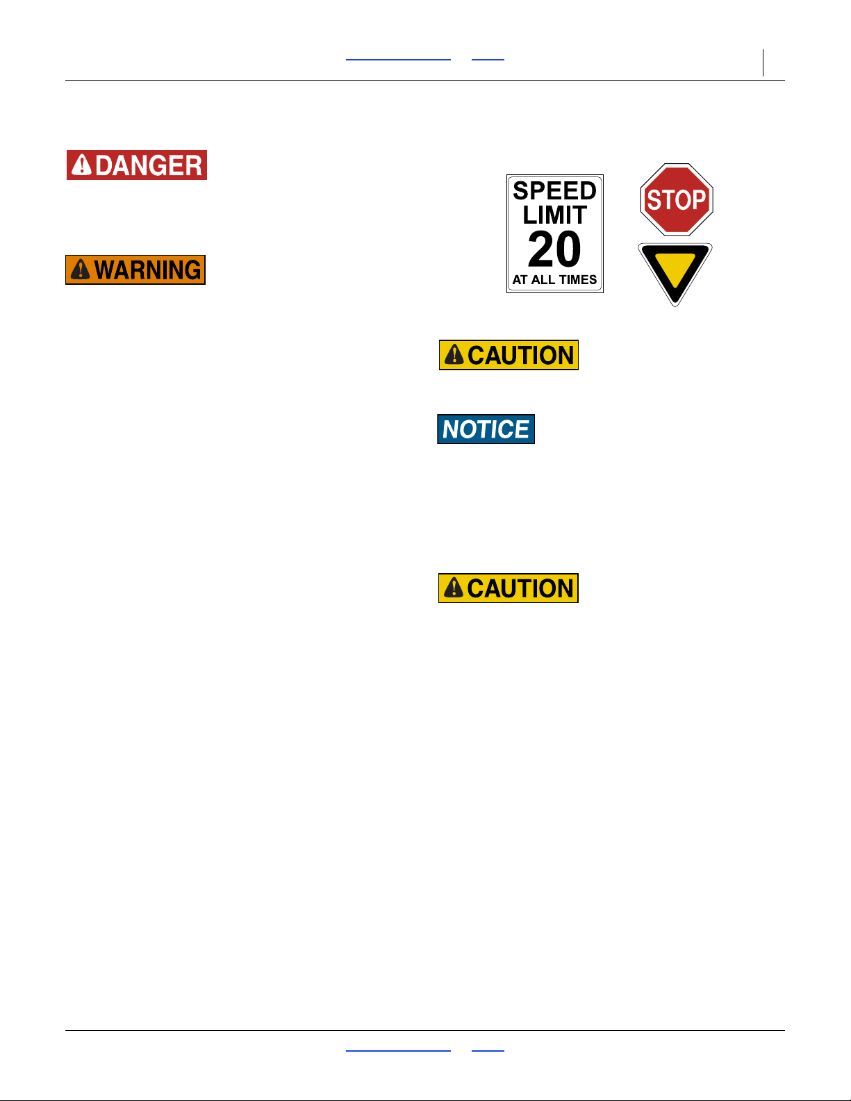
3S-5000/F/HD/HDF Table of Contents Index Operating Instructions 46
Braking and Loss of Control Hazard:
Do not exceed 20 mph when driving straight.
Reduction of Control Risk:
Seed may be loaded prior to travel, but increases stopping
distance, increases the need for caution in turns and braking,
Spill hazard/Tank damage risk:
Periodically check the tension of the straps for the fertilizer
tank. Strap tension will change as outside air temperature
changes. Adjust tension as necessary to prevent personal
injury or damage to the fertilizer tank.
Transporting the Drill
Loss of Control Hazard:
Ensure that the towing vehicle is adequate for the task. Using
an inadequate tow vehicle is extremely unsafe, and can result
in loss of control, serious injury and death.
Loss of Control Hazard:
Towing the d rill at high speeds or with a vehicle that is not
heavy enough could lead to loss of vehicle control. Loss of
vehicle control could lead to serious road accidents, injury
and death. To reduce the hazard:
Do not tow a drill that, when fully loaded, weig hs more than
1.5 times the weight of the towing vehicle.
T ransport Checklist
Before transporting the drill check the following items.
Transport only with a tractor of proper size. See
“Specifications and Capacities” on page 96
Hitch drill securely to tractor. Always use a
locking-style pin sized to match holes in hitch and
drawbar (minimum of 1-inch diameter). See
“Hitching Tract or to Drill” on page 22.
Attach safety chain to an anchor on tractor capable
of pulling drill.
Plug drill safety lights into tractor seven-pin
connector.
Make sure drill is folded properly. See “Folding” on
page 27.
Lock openers up into road position. See “Opener
Lock Up” on page 37.
Secure cylinder lock channels on transpor t-cylinder
rods and front box lift cylinders. Allow transport lift
cylinders to settle against lock channels. See
“Folding” on page 27.
Comply with all national, regio nal and local safety
laws when traveling on public roads.
Travel with caution.
2017-10-26 Table of Contents Index 195-325M
Page 51
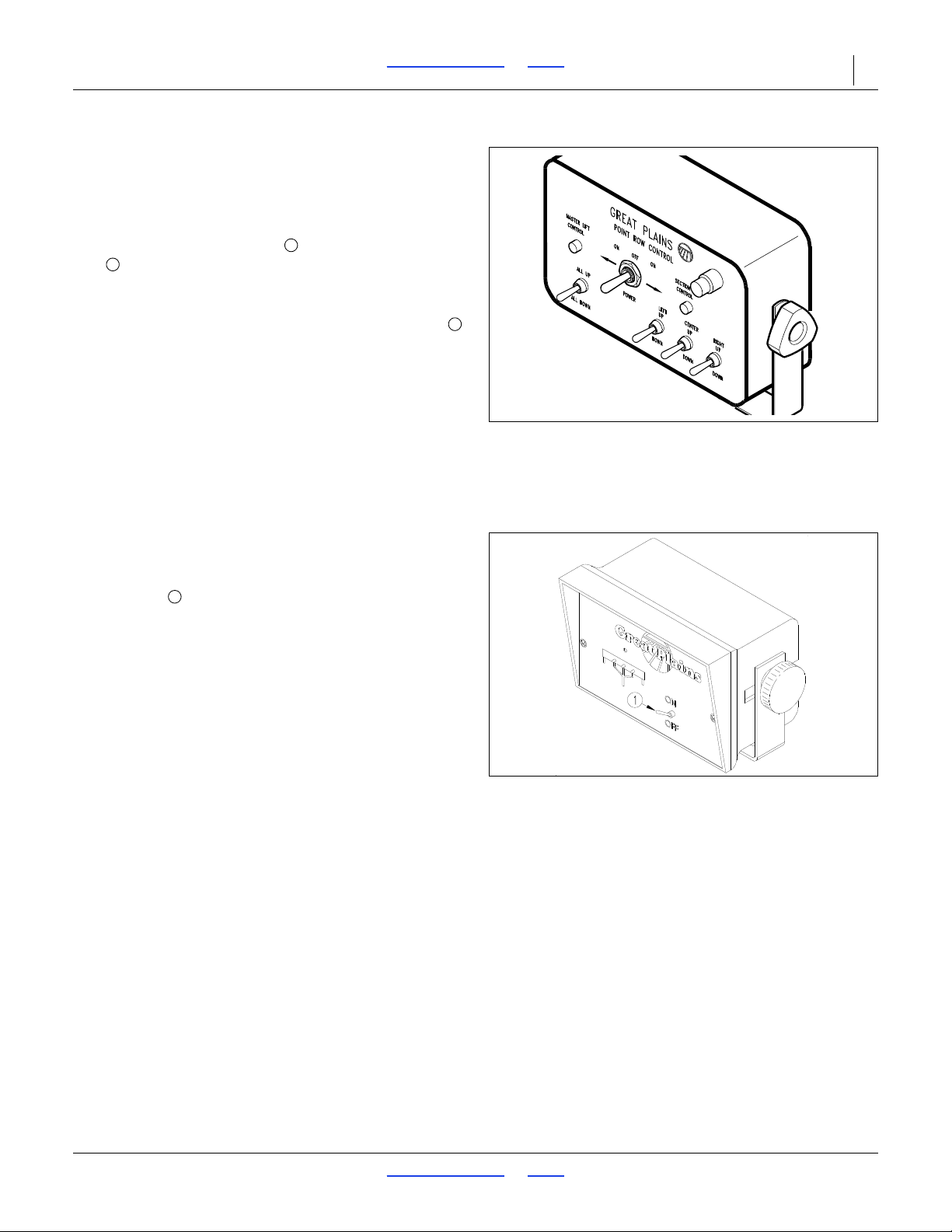
3S-5000/F/HD/HDF Table of Contents Index Operating Instructions 47
Figure 42
Point-Row Control Monitor
17060
123
Figure 43
Shaft Monitor Head
18943
1
Point Row Operation (Option)
Refer to Figure 42
The point-row option (page 92) allows you to raise and
lower openers on one drill section independent of the
others. To raise and lower openers on all sections
together, flip power switch so master-lift-control
light is on. Raise or lower all openers by moving the
switch under the light.
To raise and lower openers on one section independent
of the others, flip power s witch so section-control-light
is lit. Raise and lower openers on a section by moving
the switches under the light.
NOTE:
Turn power switch for point row of f when tractor is off.
Shaft Monitor Operation (Option)
Refer to Figure 43
The optional shaft monitor (page 94) sounds an alarm if
any seed shaft stops for more than 20 seconds.
To operate shaft monitor, turn system on by activating
on-off switch on monitor head. If seed-cup shaft is
turning, all section lights will be on and the alarm will not
sound.
If any seed-cup shaft stops for 20 seconds, an alarm will
sound and a light on the monitor will flash designating
the failed shaft.
The 20-second delay is to prevent nuisance alarms when
turning at the end of the field. If a failure does occur and
an alarm sounds, remember that you have traveled for
20 seconds without planting.
2017-10-26 Table of Contents Index 195-325M
Page 52
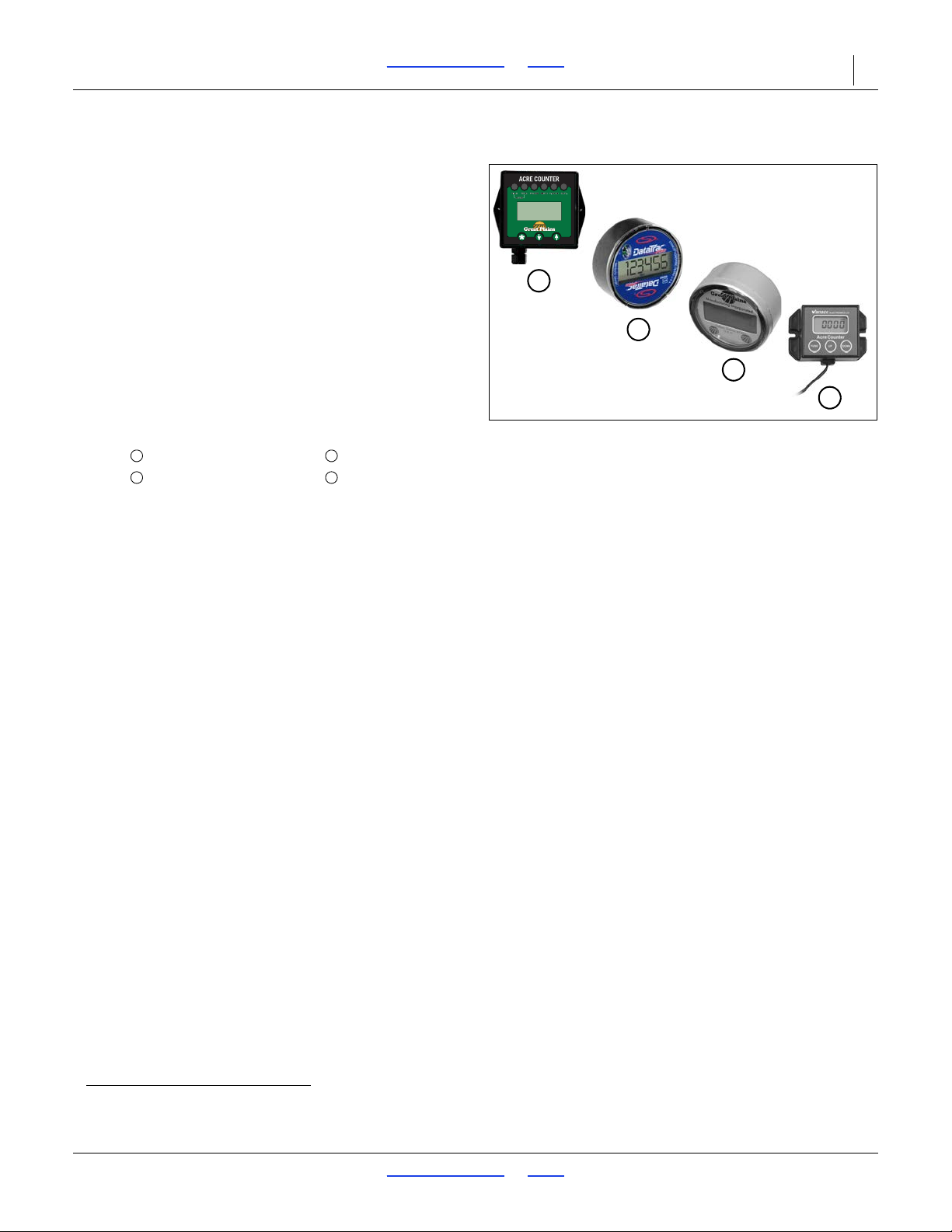
3S-5000/F/HD/HDF Table of Contents Index Operating Instructions 48
Figure 44
Acremeters
34776
34937
27378
36275
1
2
3
4
132
4
Acremeter Operation
The acremetera counts shaft rotations whenever the
shaft is rotating - normally this is only with the drill
lowered and in motion. The meter is programmed to
display rotations as acres or hectares, when using all
rows, factory-specified tires and tire inflations.
NOTE:
Unusual conditions and/or non-standard row
spacings can cause the acremeter tally to vary
somewhat from actual acres planted.
Refer to Figure 44
Acremeters supplied with model 3S-5000 Drill drills have
varied over time. For operational details (modes, resets,
calibration), see the manual supplied with the acremeter:
Meter Style and Manual
194-074M 152-314M
152-325M 194-209M
a. An electronic acremeter is available as an upgrade for older drills having a mechanical acremeter.
2017-10-26 Table of Contents Index 195-325M
Page 53
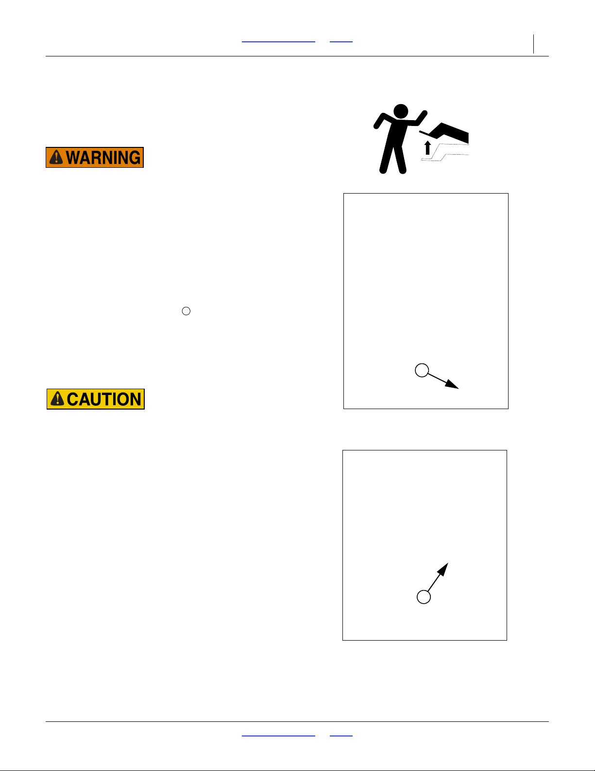
3S-5000/F/HD/HDF Table of Contents Index Operating Instructions 49
Figure 45
Parking Stand in Storage Position
18837
1
1
Figure 46
Parking Stand in Parking Position
15565
1
Parking
For information on long-term storage, see “Storage” on
page 50.
Parking with Drill Unfolded
This drill has a negative tongue weight when unfolded and
openers are raised. Lower parking stand, lower openers and
remove hydraulic down pressure bef ore unhitching the drill in
the unfolded position. Unhitching in the unfolded position with
the openers raised could result in sudden elevation of the
tongue, causing injury or death.
1. Remove jack from its storage location on top of
tongue and pin it on post on left side of tongue as
shown in Figure 11 on page 23. Extend jack until
weight of tongue is on jack.
Refer to Figure 45 and Figure 46
2. Lower parking stands located on outer ends of drill
by unpinning keeper pin and rotating stands
down. Place a block under foot of stand if it does not
contact the ground.
3. Lower openers and reduce hydraulic down pressure
to zero.
4. Unplug drill hydraulic hoses and electrical lines from
tractor.
Use caution when removing the hitch pin. Slight tongue
elevation may occur.
5. Remove hitch pin first, then safety chain from tractor
drawbar.
NOTE:
After unhitching the unfolded drill, the tongue may rise
above tractor-drawbar height. Lower tongue by
connecting the opener-lift circuit and pressurizing
openers.
Parking with Drill Folded
Always transport markers folded flat. Make sure second
marker section rests securely on transport carrier.
1. Raise, lock and fold drill into transport position.
2. Park drill on a level, solid area.
3. Remove jack from its storage location on top of
tongue and pin it on post on left side of tongue as
shown in Figure 11 on page 23. Extend jack until
weight of tongue is on jack. If ground is soft, place a
board or plate under jack to widen ground-contact
area.
4. Unplug hydraulic hoses and electrical lines from
tractor.
5. Remove hitch pin first, then safety chain from tractor
drawbar.
2017-10-26 Table of Contents Index 195-325M
Page 54

3S-5000/F/HD/HDF Table of Contents Index Operating Instructions 50
Storage
Store drill where children do not play. If possible, store
drill inside for longer life.
1. Thoroughly clean drill boxes and seed cups. Do not
store drill with seed-treatment residue in boxes and
cups.
2. Lubricate and adjust all roller chains.
3. Lubricate areas noted under “Lubrication”
beginning on page 83. Take special care to oil seed
cup drive sprockets in the square bore.
4. Lock opener frames up for transport or disconnect
seed and fertilizer hoses from openers. Leaving
seed hoses connected when storing drill with
openers lowered will cause permanent stretching
and cracking of hoses.
5. Inspect drill for worn or damaged parts. Make repairs
and service during the off season.
6. Use spray paint to cover scratches, chips and worn
areas on the drill to protect the metal.
7. Cover with a tarp if stored outside.
2017-10-26 Table of Contents Index 195-325M
Page 55
3S-5000/F/HD/HDF Table of Contents Index Adjustments 51
Adjustments
To get full performance from your drill, you need an
understanding of all component operations, and many
provide adjustments for optimal field results.
The Model 3S-5000/F/HD/HDF has double-disc 00 or
00HD Series openers with depth-controlling press
wheels mounted on floating opener frames. Opener
bodies are staggered for easy soil flow. All openers pivot
on a common axis to maintain consistent depth as the
opener frames follow contours. A spring provides the
down pressure necessary for opener double discs to
open a seed furrow. The spring allows openers to float
down into depressions and up over obstructions.
Individual openers can be adjusted to account for tire
tracks.
NOTE:
Even if your planting conditions rarely change, some
of these adjustment items need periodic attention
due to normal wear.
Seed and Fertilizer Rate
Materials are applied by fluted feed meters driven by the
left end wheel. Independent mechanisms drive main
seed, fertilizer and optional small seeds application.
Adjustment Page The Adjustment Affects
Setting Main Box Seed Rate SRM
Setting Drive Type SRMaCoarse control of seeding rate
Main Box Seed Rate Handle SRM
Position Seed Cup Doors SRMaConsistent seed delivery for certain seed sizes
Setting Fertilizer Rate SRM
Small Seeds Rate SRMaSmall seeds population
Hitching Tractor to Drill 22
Adjusting the Drill Hitch 22 Frame Level
Leveling the Drill 18 Frame Level
Opener Frame Adjustment 54 Consistent seeding depth
00 Row Unit Adjustments 59-60 Consistent seeding depth
Opener Height 61 Seeding depth in tire tracks
Row Unit Down Pressure (Spring) 61 Level row units and consistent seeding depth in tire tracks
00 Series Disk Scraper Adjustment 67 Consistent seeding depth
Seed Firmer Adjustments 67 Consistent seed placement and coverage
Dry Fertilizer Tube Adjustment 63 Optimal fertilizer placement
00 & 00HD Series Opener Depth 68 Seeding depth.
Marker Adjustments 68 Marker folding operation, intended swatch spacing
a. SRM: Seed Rate Manual: This adjustment is described in manual 195-325B.
a
a
a
Main Box Seed rate is controlled by adjustments for:
• Drive Type gearbox lever
• Seed Rate Handle at box (drill front)
• Feed Cup Door (one each seed tube)
Fertilizer rate is controlled by:
• Rate Adjuster at box (drill rear)
Small Seeds rate is controlled by:
• Rate Handle at box (drill rear)
Planting Depth
Setting nominal planting depth, and achieving it
consistently, is affected by multiple adjustable drill
functions, from greatest to least effect they are:
• 00 & 00HD Series Opener Depth,
• Hydraulic Down Pressure All Openers,
• Row Unit Down Pressure (Spring),
• Opener Height, and;
• 00 Row Unit Adjustments (as blades wear)
Fine control of seeding rate
Fine control of application rate
2017-10-26 Table of Contents Index 195-325M
Page 56
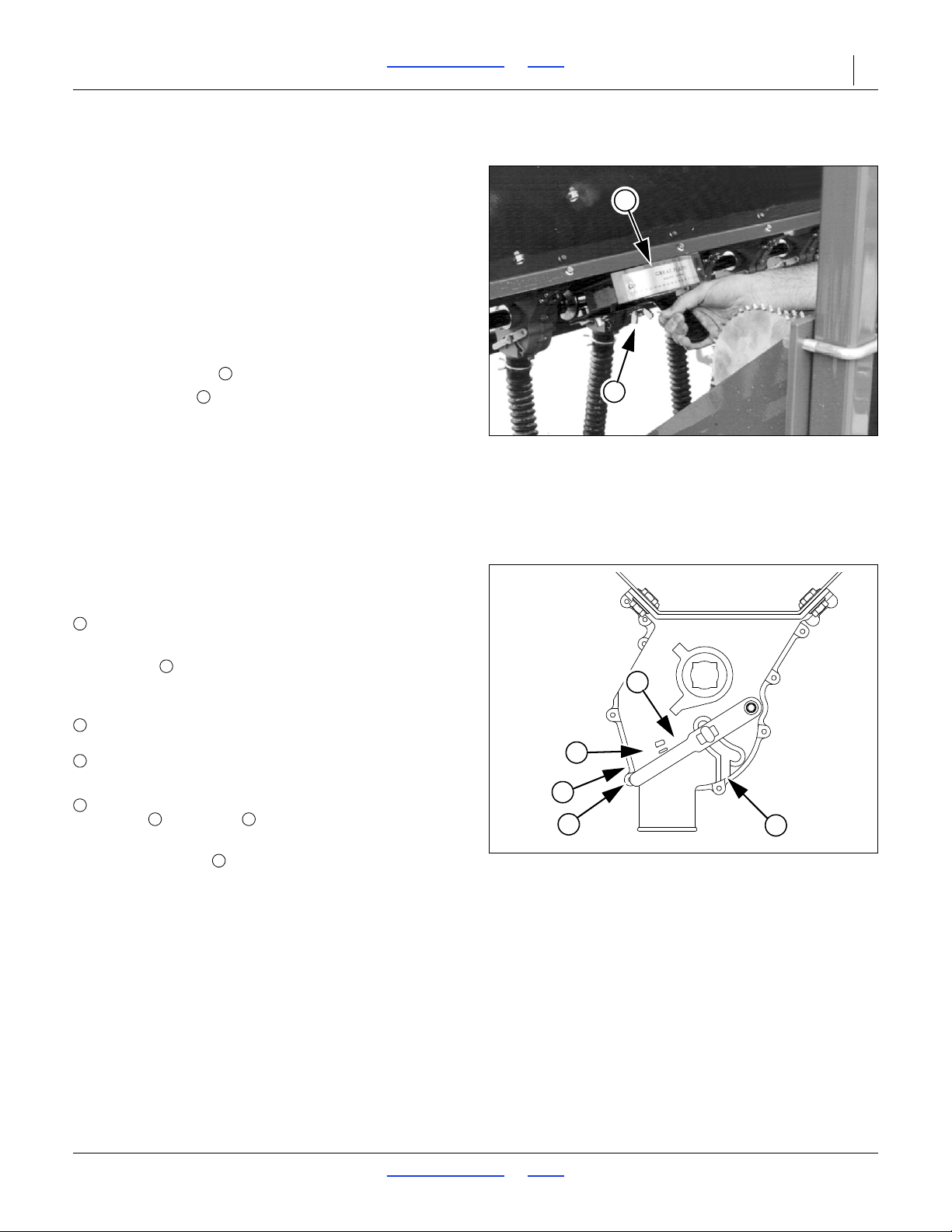
3S-5000/F/HD/HDF Table of Contents Index Adjustments 52
Figure 47
Seed Rate Handle
17618
2
1
1
2
1
4
2
3
5
Figure 48
Seed Cup Door Handle
26211
3412323
5
Main Box Seed Rate Handle
Refer to Figure 47
There are main box seed rate handles for each section of
the drill (3 handles total). Generally, all need to be set
identically, and you need to calibrate only one section.
The seed rate handle controls the percent engagement
of the seed sprocket in each seed cup. The initial setting
of the handle is given by the Seed Rate Chart.
You can temporarily stop seed flow to a drill section by
setting a handle to zero.
To set a handle:
1. Loosen wing nut under handle.
2. Set indicator to just past value from Seed Rate
Chart.
3. Tighten wing nut.
Position Seed Cup Doors
Refer to Figure 48,
which depicts the seed cup door handle in position
.
At each main seed box seed tube, adjust the seed cup
door handle for the seed size.
The handle has three normal operating position detents:
(top detent) is for the smallest seeds.
Use it for wheat and similar small seeds.
(middle detent) is for larger seeds.
Use it for soybeans and similar larger seeds.
(bottom detent) is for oversize or fragile seeds.
If you experience excessive cracking with
setting , use setting .
NOTE:
Handle position is used for clean-out, not pla nting.
If set to this position with seed loaded, it may be
difficult to reset it to a normal operating position.
2017-10-26 Table of Contents Index 195-325M
Page 57
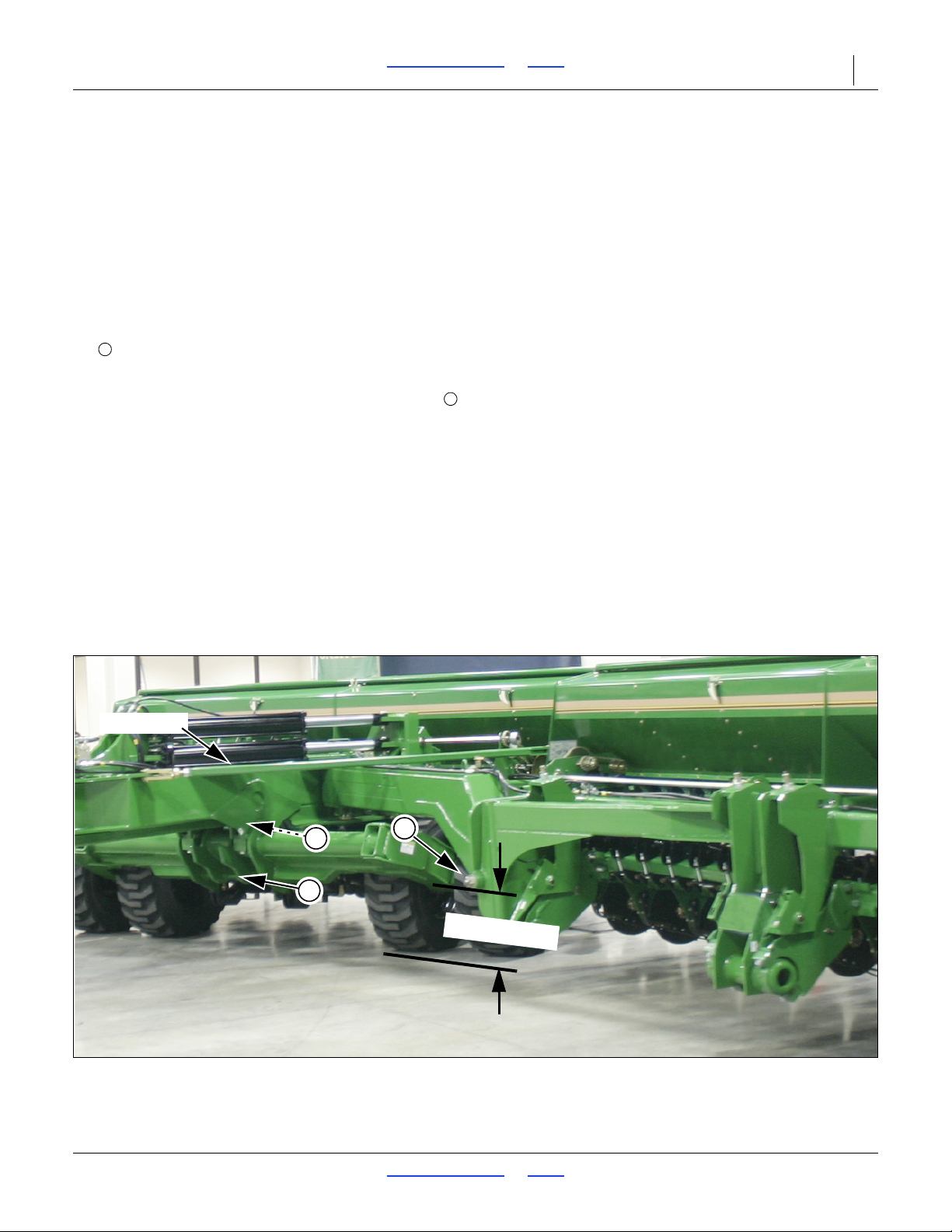
3S-5000/F/HD/HDF Table of Contents Index Adjustments 53
1
2
Figure 49
Tool Bar and Link Tube Adjustments
34302
Truss Tube
1
T
o
o
l B
a
r
H
e
igh
t
2
2
Frame Adjustments
Tool Bar Height Adjustment
Tool Bar height is factory set and normally will not require
adjustment. If you tear down the drill for repair or if the
tool bar is visibly not level, spacer washers on vertical
pivot pins allow for a small amount of tool bar-height
adjustment.
Refer to Figure 49
To check tool bar height, park drill on a level surface.
Measure from ground to centerline of horizontal pivot
pin . If dimension on either side of drill varies more
1
than
/4inch, adjust tool bar height.
To adjust tool bar height, reposition spacer washers .
First lower openers and set enough opener down
pressure to help balance frame. Raise tool bar by
removing spacer washers from top of the vertical pivot
and placing them on bottom side of pivot. Lower tool bar
by removing spacer washers from bottom of vertical pivot
and placing them on top of pivot.
Truss Tube
Provide a small amount of tension on truss tube to help
hold draft load from tool bars.
2017-10-26 Table of Contents Index 195-325M
Page 58
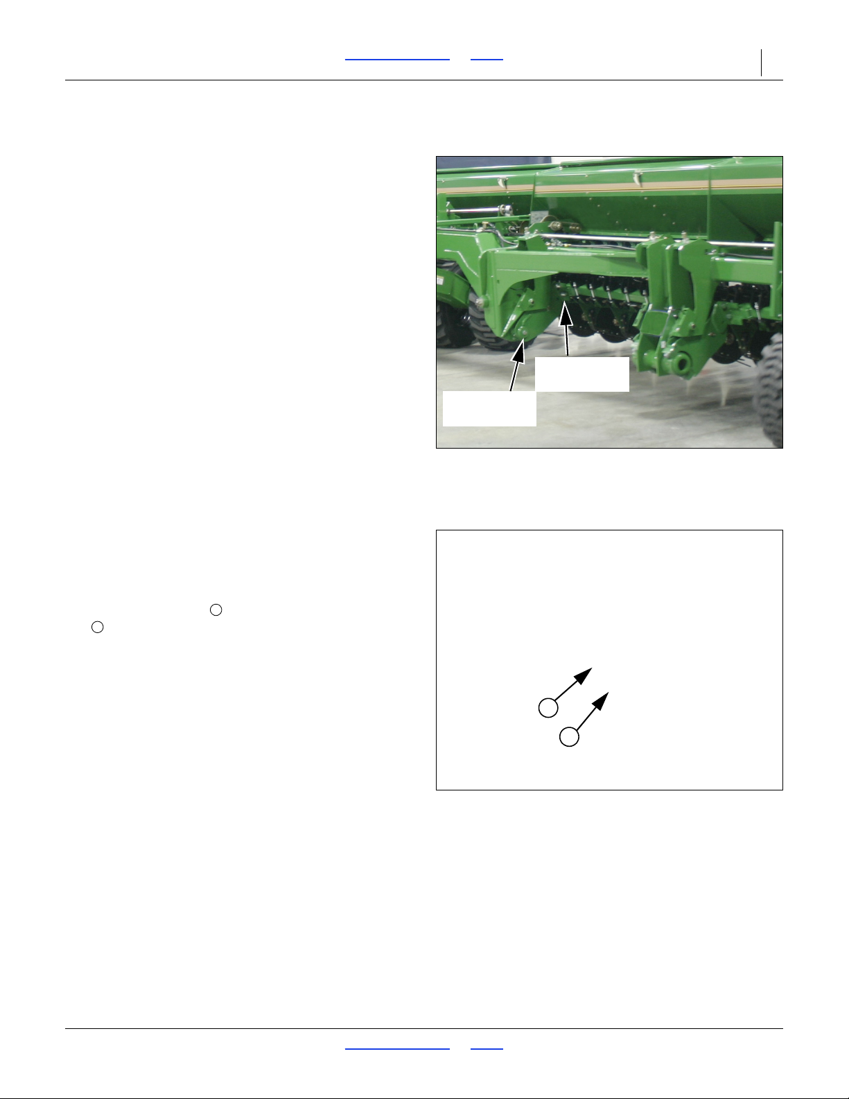
3S-5000/F/HD/HDF Table of Contents Index Adjustments 54
Figure 50
Opener Frame
34303
Opener Frame
Pivot
Opener Frame
Adjustment
Figure 51
Opener Frame Adjustment
15558
1
2
1
2
Opener Frame Adjustment
Refer to Figure 50
Each drill section has an opener frame which pivots
about the centerline of the drill gauge wheels. These
floating opener frames have the ability to rock the
openers 15 degrees up and 15 degrees down as a
group. By pivoting at the gauge wheels, openers
maintain a consistent depth as opener frames rock up
and back.
Down pressure for each opener frame is provided by two
cylinders working on a constant lever arm. When
combined with live hydraulics, the cylinders provide
constant down pressure across the widt h of each op ener
frame – regardless of how the frame is positioned. Two
cylinders per opener frame along with special trunnions
also provide some ability for one end of an opener frame
to rock independent of the other while maintaining
constant opener down pressure across the frame. A
pressure-control valve on each circuit allows you to
adjust down pressure.
The opener frame has one adjustment point for two
different operating positions, one for drilling with normal
down pressure and another for drilling with high down
pressure.
Refer to Figure 51
You can adjust opener frames between two operating
positions–one for normal down pressure and one for
higher down pressure. The adjustment is near the
opener frame pivots. There are three holes and two
bolts. The bottom bolt serves as the pivot. The top
bolt is for adjustment.
For normal drilling conditions, keep top bolt in second
hole. Use this setting when drilling with opener down
pressure below 1600 psi.
When drilling with opener down pressure above
1600 psi, place top bolt in top hole on all six pivot points
across drill.
2017-10-26 Table of Contents Index 195-325M
Page 59
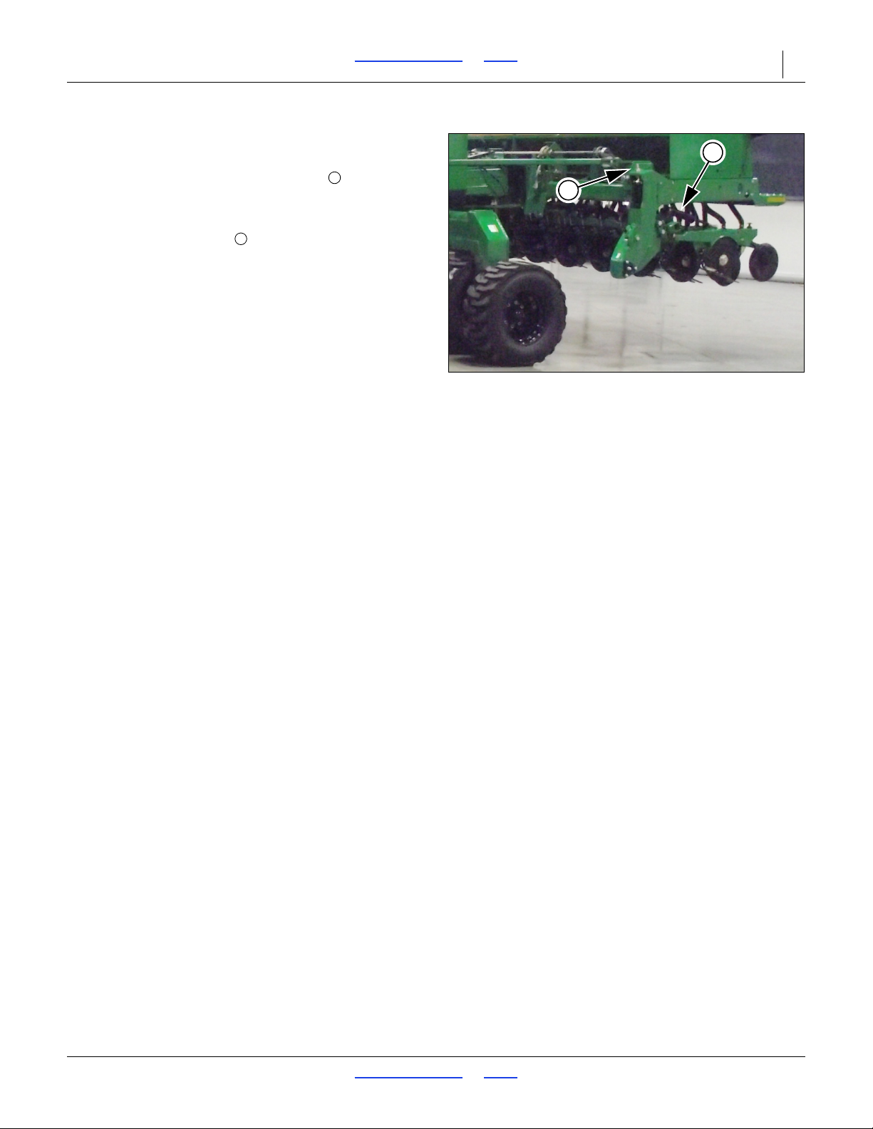
3S-5000/F/HD/HDF Table of Contents Index Adjustments 55
Figure 52
Opener Frame Clearance
34328
1
2
1
2
Opener Frame Clearance
Refer to Figure 52
When fully raised, top of opener mounts should clear
bottom of drill frame tube by at least
To adjust opener frames so all openers have the same
clearance, loosen jam nut on opener lift cylinders and
turn adjustment nut. When openers are at the correct
height, tighten jam nut. Repeat at each opener lift
cylinder if necessary .
1
/2inch.
2017-10-26 Table of Contents Index 195-325M
Page 60
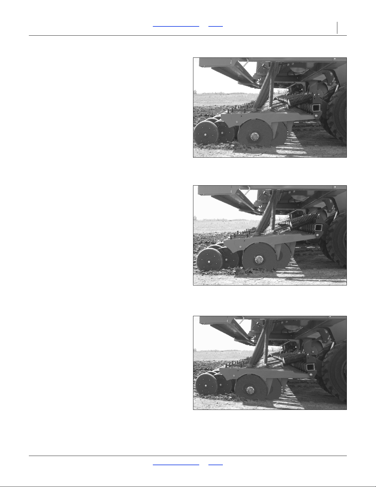
3S-5000/F/HD/HDF Table of Contents Index Adjustments 56
Figure 53
Frame & Opener Level
29131
Figure 54
Openers Too High in Front
29132
Figure 55
Openers Too Low in Front
29133
Frame Level
Refer to Figure 53
The 00HD Series openers are designed to produce
optimal results when the opener frames are level with the
ground. Operating with drill frame level is also
recommended, and this is set by hitch height, see
“Adjusting the Drill Hitch” on page 22.
If planting depth is not as desired check and adjust the
following items:
• opener sub-frame adjustment: all gauge wheel
trunnions in same frame pivot holes
• opener pivot height: all openers pivoting in same
hole at their mounts (possi bly excepting rows in tire
tracks) see “Opener Height” on page 61,
• opener press wheel height: all row units set the
same - see “Opener Height” on page 61, and;
• opener spring down-force: all row units set the same
(possibly excepting rows in tire tracks) see “Row
Unit Down Pressure (Spring)” on page 61.
Refer to Figure 54
This illustrates openers too high in front. Increase
hydraulic pressure and/or lengthen opener springs.
Check sub-frame pivot in use at higher pressures.
Refer to Figure 55
This illustrates openers too low in front, also known as
"bulldozing". Decrease hydraulic pressure and/or
shorten opener springs.
Check sub-frame pivot if pressures have recently been
reduced.
2017-10-26 Table of Contents Index 195-325M
Page 61
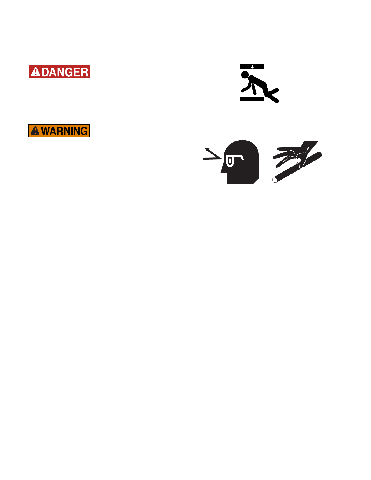
3S-5000/F/HD/HDF Table of Contents Index Adjustments 57
Hydraulic Down Pressure All Openers
Crushing Hazard:
You will be seriously injured or killed if you are caught
between raising openers and drill frame. Always stop tractor
engine, set park brake, and remove key before adjusting or
servicing openers. Keep all bystanders well away during drill
operation.
High Pressure Fluid Hazard:
Escaping fluid under pressure can penetrate the skin causing
serious injury. Avoid the hazard by relieving pressure before
disconnecting hydraulic lines. Use a piece of paper or
cardboard, NOT BODY PARTS, to check for suspected leaks.
Wear protective gloves and safety glasses or goggles when
working with hydraulic systems. If an accident occurs, see a
doctor immediately.
Opener down pressure controls opener penetration and
press-wheel soil firming. Use only enough down
pressure to cut a furrow and maintain proper soil-firming
over seed. Excessive opener down force may cause
bulldozing of the openers in light soil conditions, and will
lead to premature wear on opener components.
2017-10-26 Table of Contents Index 195-325M
Page 62
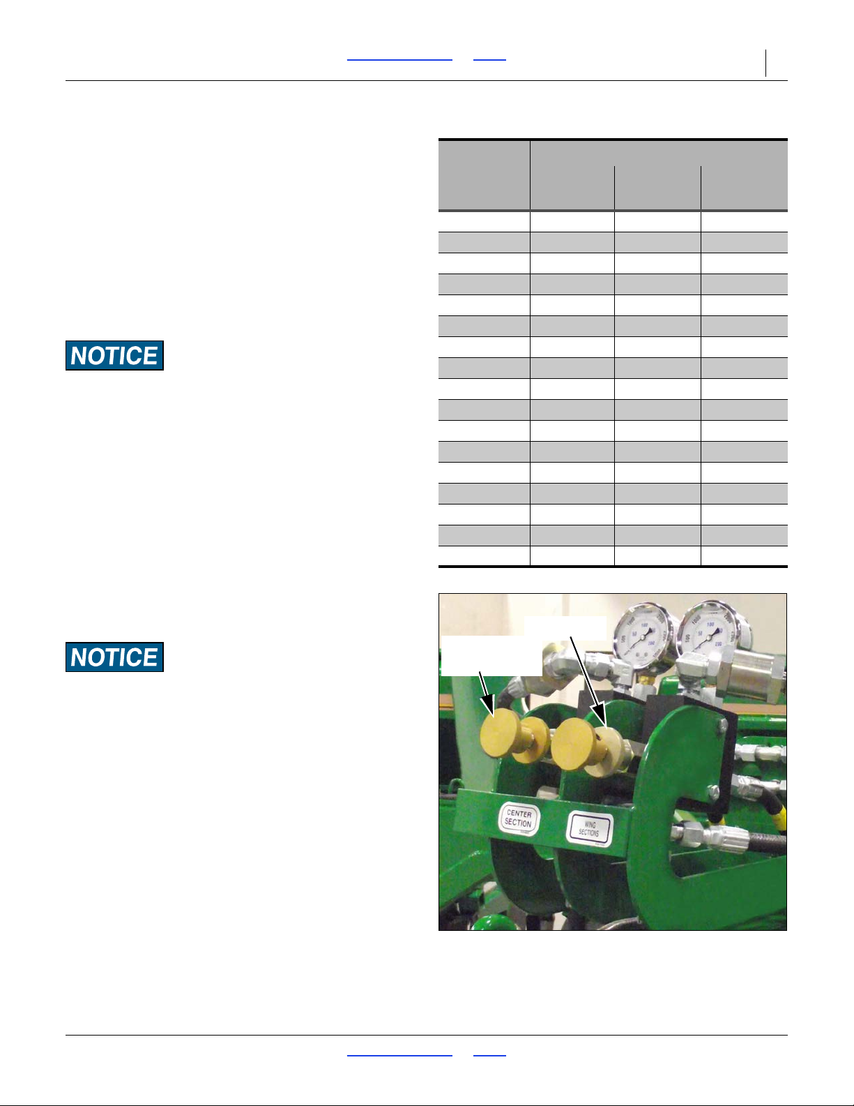
3S-5000/F/HD/HDF Table of Contents Index Adjustments 58
Hydraulic Down-Force
Gauge
Setting
Pounds of Force at Opener Disks
6 inch
rows
7 1/2 inch
rows
10 inch rows
200 PSI 83 86 92
300 PSI 90 95 102
400 PSI 97 103 11 3
500 PSI 103 111 124
600 PSI 1 10 119 135
700 PSI 117 128 146
800 PSI 123 136 157
900 PSI 130 144 167
1000 PSI 137 152 178
1 100 PSI 143 161 189
1200 PSI 150 169 200
1300 PSI 157 177 211
1400 PSI 163 185 222
1500 PSI 170 194 233
1600 PSI 176 202 244
1700 PSI 183 210 254
1800 PSI 190 218 264
Figure 56
Pressure Control Valves
34293
Adjustment
Knob
Lock Disk
Table at right shows the approximate force at openers for
a given pressure at the pressure control valve.
NOTE:
To account for additional compaction from drill and
tractor tires, set pressure on cent er openers slightly
higher than wing openers.
To run the drill with constant opener down pressure
requires an Active Hydraulic System. An Active
Hydraulic System requires a tractor with closed-center
hydraulics or pressure/flow compensated hydraulics
powered by a variable displacement hydraulic pump. (If
you are not familiar with your tractor’s hydraulics, consult
your tractor dealer.)
Tractors with load-sensing hydraulics must use the bypass
valve to operate the 3S-5000/F/HD/HDF. Failure to use the
bypass valve can cause major tracto r damage. Before
adjusting opener down pressure, set bypass valve as explained
under “Setting the Bypass Valve” on page 31.
NOTE:
T o run the drill on tractors with open-center hydraulics
or on tractors with fixed displacement hydraulic
pumps you must install a Great Plains kit, part number
194-143A. Contact your Great Plains dealer for
ordering information. See “Non-Active Hydraulic
System” on page 35.
To set down pressure:
1. Lower openers to the ground. Lock hydraulic lever
forward for constant hydraulic flow.
You must lock hydraulic lever forward. See “Opener
Operation” on page 33, for instructions.
Refer to Figure 56
2. Turn knob on pressure-control valve while watching
pressure gauge, turn knob until gauge shows
desired pressure. Turn clockwise to increase
pressure. Turn counterclockwise to decrease
pressure.
There is one pressure-control valve for openers on
the center section and one for openers on the wing
sections of the drill.
As a general starting point, set hydraulic down
pressure to 1000 psi. For most field conditions,
adjust down pressure between 200 and 1600 psi.
2017-10-26 Table of Contents Index 195-325M
Page 63
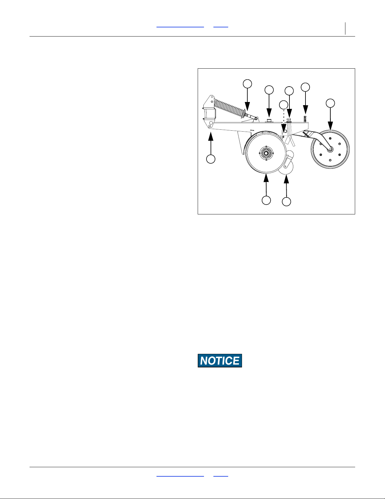
3S-5000/F/HD/HDF Table of Contents Index Adjustments 59
Figure 57
00 Series Row Unit
34233
1
2
3
5
4
6
9
7
8
00 Row Unit Adjustments
Refer to Figure 57 (which depicts a row unit fully
populated with all optional accessories [except
scraper and Keeton
Model 3S-5000/F/HD/HDF drills)
From front to back, a 00 Series row unit can include the
following capabilities (some optional):
1. Opener height adjustment: standard
If a few rows need to run deeper, such as in tire
tracks, the arm’s pivot point may be lowered. See
“Opener Height” on page 6 1.
2. Single Down Pressure Spring: standard
Each row unit is mounted on the drill as a pivoting
arm which allows the row unit to independently move
up and down. The adjustable spring provides the
force to get the row unit and attachments into the
soil. See “Row Unit Down Pressure (Spring)” on
page 61.
3. Disc Blades: standard, 2 per row unit
Double disc blades open a furrow, creating the seed
bed. Spacers adjust the blades for a clean furrow.
See “00 Row Unit Adjustments” on page 59.
4. Main seed delivery tube: standard
No adjustments are necessary.
5. Disc Scraper: standard (not shown)
In sticky soils, a scraper helps keep the opener discs
operating freely. A slotted scraper is standard.
A spring-loaded carbide scraper is optional. See
“Carbide Disc Scraper” on page 90.
6. Seed firmer:
seed flap (not shown) standard:
®
] supported for use with the
7. Fertilizer delivery tube: optional
The tube may be reversed to drop fertilizer with the
main seed, or just ahead of the press wheels.
8. Small Seeds delivery tube: optional
The tube may be reversed to drop small seed near
the main seed tube, or just ahead of the press
wheels.
Seed-Lok
Improves seed-soil contact. See “00 Series
Seed-Lok
Keeton
Improves seed-soil contact, and provides a stable
arm for a low-rate liquid fertilizer delivery tube. See
“Keeton
®
firming wheel (shown)
®
Lock Up” on page 67.
®
seed firmer (not shown)
®
Seed Firmer Adjustment” on page 67.
If fertilizer is also installed, the Small Seeds tube is
mounted outside the opener frame.
9. Press wheels: standard (choice of types)
These close the seed trench. The wheels also
support the free end of the row unit, and provide the
primary control over seeding depth. See “00 & 00HD
Series Opener Depth” on page 68.
Equipment Damage Risk:
Do not back up with row units in the ground. To do so will
cause severe damage and row unit plugging.
2017-10-26 Table of Contents Index 195-325M
Page 64
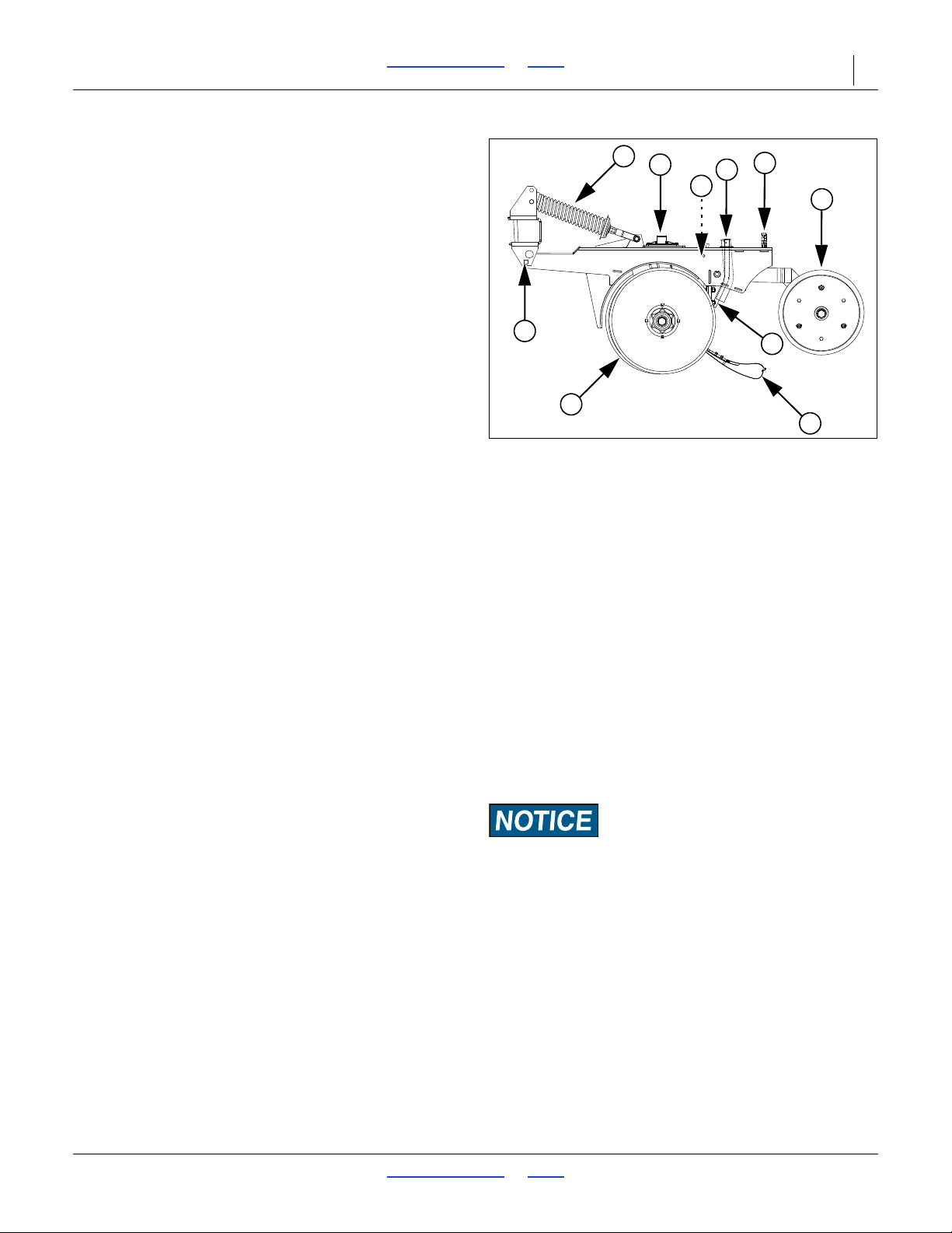
3S-5000/F/HD/HDF Table of Contents Index Adjustments 60
Figure 58
00HD Series Row Unit
26427
1
2
3
7
4
8
9
5
6
6
00HD Row Unit Adjustments
The 3S-5000/F/HD/HDF has double-disk openers with
depth-controlling press wheels mounted on floating
opener frames. Opener bodies are staggered for easy
soil flow. All openers pivot on a common axis to maintain
consistent depth as the opener frames follow contours. A
spring provides the down pressure necessary for opener
double disks to open a seed furrow. The spring allows
openers to float down into depressions and up over
obstructions. Individual openers can be adjusted to
account for tire tracks.
Refer to Figure 58 (which depicts a row unit fully
populated with all optional accessories supported for
use with the 3S-5000/F/HD/HDF drill)
From front to back, a Great Plains 00HD Series row unit
can include the following capabilities (some optional):
1. Opener height adjustment: standard
If a few rows need to run deeper, such as in tire
tracks, the arm’s pivot point may be lowered. See
“Opener Height” on page 6 1.
2. Single Down Pressure Spring: standard
Each row unit is mounted on the drill as a pivoting
arm which allows the row unit to independently move
up and down. The adjustable spring provides the
force to get the row unit and attachments into the
soil. See “Row Unit Down Pressure (Spring)” on
page 61.
3. Disc Blades: standard, 2 per row unit
Double disk blades open a furrow, creating the seed
bed. Spacers adjust the blades for a clean furrow.
See “00 Row Unit Adjustments” on page 59.
4. Main seed delivery tube: standard
No adjustments are necessary.
5. Fertilizer delivery tube: optional
The tube may be reversed to drop fertilizer with the
main seed, or just ahead of the press wheels.
6. Small Seeds delivery tube: optional
The tube may be reversed to drop small seed near
the main seed tube, or just ahead of the press
wheels.
If fertilizer is also installed, the Small Seeds tube is
mounted outside the opener frame.
7. Disk Scraper: optional
In sticky soils, a scraper helps keep the opener disks
operating freely. See “Carbide Disc Scraper” on
page 90.
8. Seed firmer: seed flap (not shown) standard:
Keeton
Improves seed-soil contact, and provides a stable
arm for a low-rate liquid fertilizer delivery tube. See
“Keeton
Seed-Lok
Improves seed-soil contact. See “00 Series
Seed-Lok
9. Press wheels: standard (choice of types)
These close the seed trench. The wheels also
support the free end of the row unit, and provide the
primary control over seeding depth. See “00 & 00HD
Series Opener Depth” on page 68.
Equipment Damage Risk:
Do not back up with row units in the ground. To do so will
cause severe damage and row unit plugging.
®
seed firmer (shown)
®
Seed Firmer Adjustment” on page 67.
®
firming wheel (not shown)
®
Lock Up” on page 67.
2017-10-26 Table of Contents Index 195-325M
Page 65
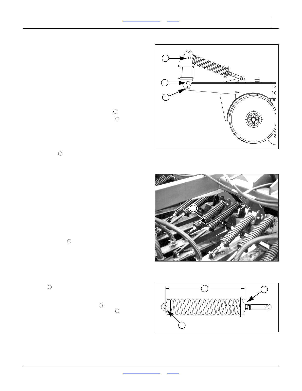
3S-5000/F/HD/HDF Table of Contents Index Adjustments 61
Figure 59
Pivot Point Bolt Holes
26382
2
1
3
1
2
3
Figure 60
Row Unit Spring Tension
17158
1
1
Figure 61
00 Series Spring Length
26454
3
2
4
234
Opener Height
The depth to which the opener disc blades penetrate the
soil is controlled in front by the tool bar and pivot (opener
height), and in the back by the press wheel heig ht .
If the actual ground level is lower for some rows, such as
those in tire tracks, you can lower that row unit by
lowering the pivot point.
Refer to Figure 59
1. Raise the drill just enough to relieve tension in the
down-pressure spring.
2. Remove the bolt from the upper hole .
3. Re-position the arm at the lower hole , and secure
with bolt.
NOTE:
No spring tension or position adjustment is required.
The pivot holes are designed for neutral effect on
spring tension (the bolt at the top end of the spring
uses a hole that depends on spring length, and not
opener height.)
Row Unit Down Pressure (Spring)
For planting in tire tracks, and no-till conditions, you can
increase spring pressure on individual or on all openers.
Adjust the spring in conjunction with the subframe
down-force, and opener height, to keep the top of the
row unit parallel to the ground.
Adjusting pressure at the springs for all rows is not
recommended. Use the opener frame pivot pin.
Refer to Figure 60 and Figure 61
To increase spring pressure:
1. Loosen jam nut at lower end of opener spring.
2. Tighten flange against spring tension.
NOTE:
3. After adjusting, lock flange nut in place with jam nut.
The length of the spring is factory-set to:
5
13
The reference points for this length are the
center of the upper/front clevis pin and
the base of the lower/rear spring stop cup .
The factory preset length is recommended for
conventional till and min-till conditions. Shorten it for
rows in tire tracks or more difficult min-till conditions. The
minimum recommended length is:
5
12
1
Each
force at opener disc (approximately 9 kg per cm). Do
not tighten nut more than one inch (2.5 cm).
/16 inches (33.8 cm).
/16 inches (31.3 cm).
/4 inch adjustment adds about 13 pounds of
2017-10-26 Table of Contents Index 195-325M
Page 66
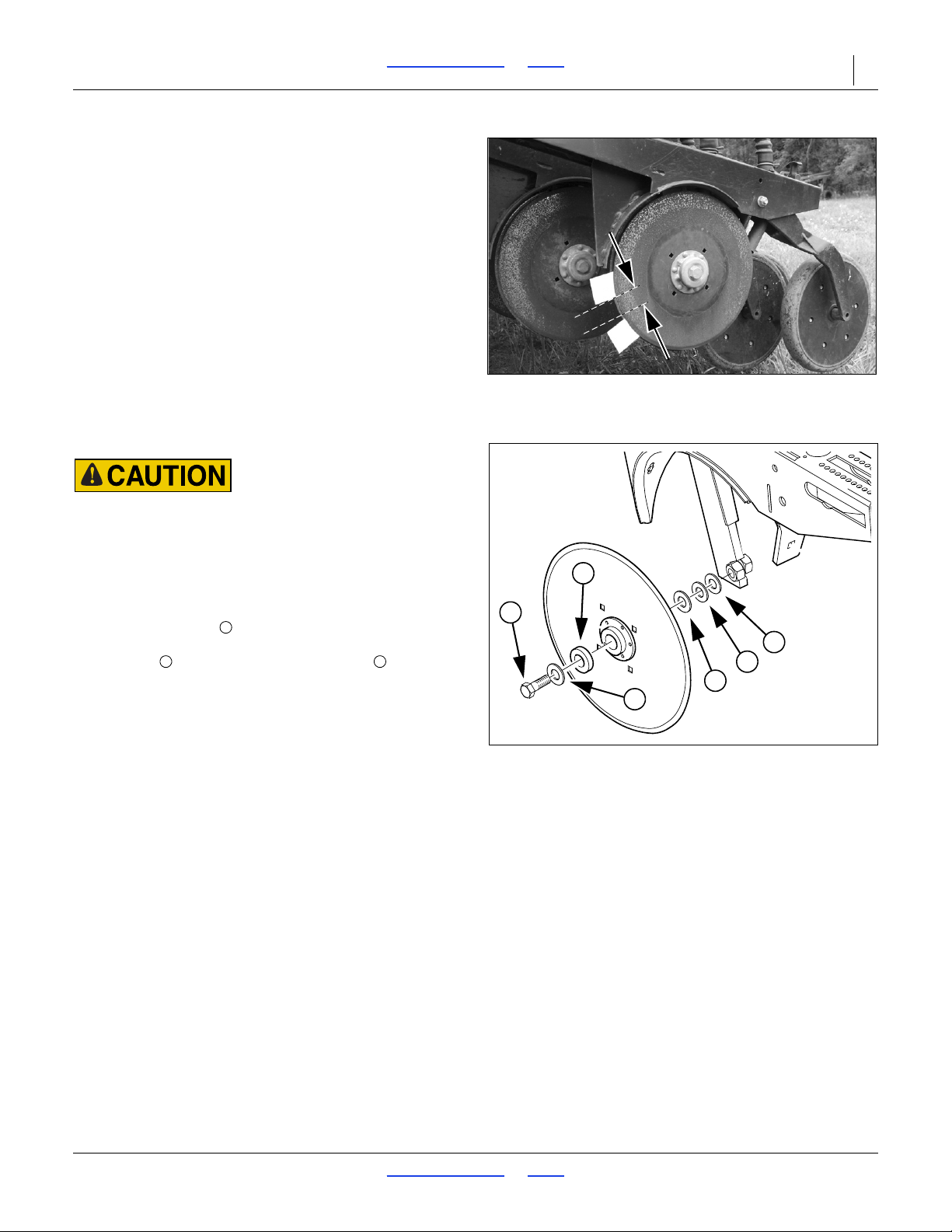
3S-5000/F/HD/HDF Table of Contents Index Adjustments 62
Figure 62
Checking Disc Contact
26451
Figure 63
Adjusting Disc Spacers
26385
2
1
3
3
3
3
132
Disc Blade Adjustments
Opener disc angle and stagger is not adjustable, but
disc-to-disc spacing is, and may need attention as discs
experience normal wear. Spacers must be reset when
blades are replaced.
Refer to Figure 62
The ideal spacing causes the blades to be in contact for
about one inch. If you insert two pieces of paper between
the blades, the gap between them should be 0 to 1.75 in.
(0 to 4.4 cm).
If the contact region is significantly large r or smaller (or
there is no contact at all), it needs to be adjusted by
moving one or more spacer washers. If the contact
region varies with blade rotation, one or both blades is
likely bent and in need of replacement.
Adjusting Disc Contact
Sharp Object Hazard:
Use caution when making adjustments in this area. Row unit
disc blades may be sharp.
Refer to Figure 63
1. Raise the openers and lock them with the transport
pin.
2. Remove the bolt retaining the opener disc on one
side. Carefully remove the disc, noting how many
spacers are outside the disc bearing and inside
the disc. Do not lose the hub components and
spacer washers.
3. To reduce the spacing between the discs (the normal
case), move one spacer washer from the inside to
the outside of the disc.
4. Re-assemble and check disc contact.
2017-10-26 Table of Contents Index 195-325M
Page 67
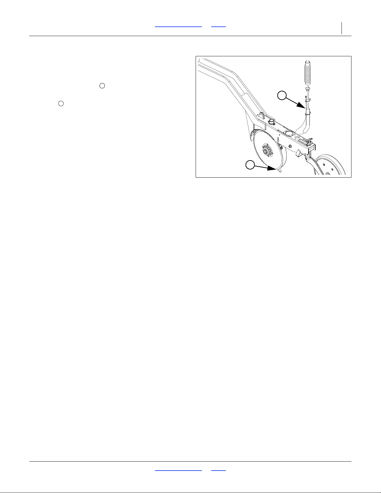
3S-5000/F/HD/HDF Table of Contents Index Adjustments 63
Figure 64
Fertilizer Tube Forward
32236
1
2
1
2
Dry Fertilizer Tube Adjustment
Refer to Figure 64
Deeper dry fertilizer placement may be achieved by
rotating the fertilizer tube to face forward.
This orientation is suggested only if the seed firmer is a
seed flap . If a Keeton
fertilizer falls on the firmer and may be scattered rather
than placed deeper.
®
or Seed-Lok® is present,
2017-10-26 Table of Contents Index 195-325M
Page 68
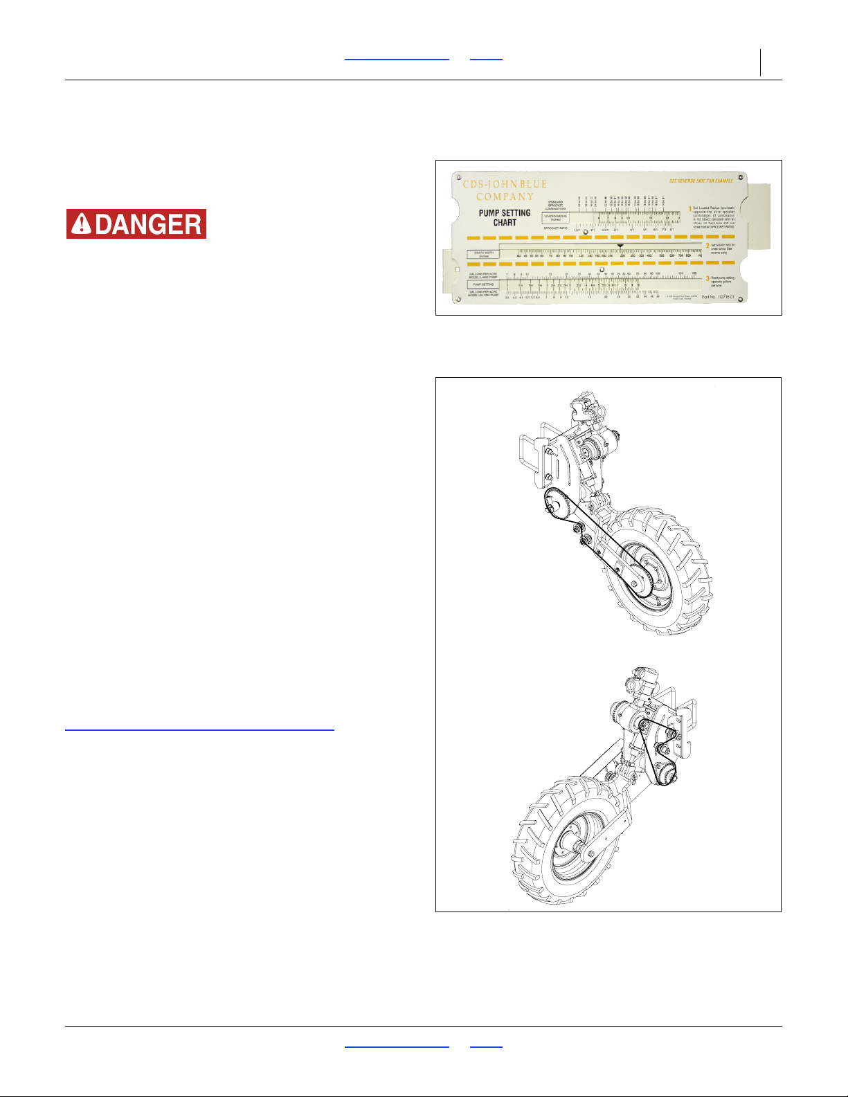
3S-5000/F/HD/HDF Table of Contents Index Adjustments 64
Figure 65
115698-91 Pump Slide Chart
29981
Figure 66
Fertilizer Transmission
36288
Liquid Fertilizer Adjustments (Option)
This section is a summary. For detailed instructions, as
well as fertilizer rate and orifice sizing charts, see the
Seed and Fertilizer Rate manual (195-325B).
Agricultural Chemical Hazards:
Avoid contact with skin or eyes. Wear proper protective
equipment as required by chemical manufacturer. Avoid
prolonged breathing of chemical fumes. Wear respirator as
required by chemical manufacturer.Some chemicals will cause
serious burns, lung damage, and death. Seek medical
assistance immediately if accident occurs. Know what to do in
case of accident.
Rate is positively set by the drive system and pump.
Adjustments to orifice plates must also be made to
provide back-pressure keeping the boom within a
specific pressure range to assure consistent delivery.
Ideal manifold pressure is between 15 and 40 psi.
A check valve at each nozzle prevents flow below
approximately 8 psi, preventing boom drainage during
turns and non-planting moves. Operating at pressure too
low may cause some nozzles to close, resulting in
uneven flow row-to-row.
A relief valve at the boom inlet protects the system from
over-pressure. Above approximately 65 psi, material is
diverted to a dump line.
Great Plains recommends checking with your local
agronomist as soil conditions vary. Soil conditions in your
area may need less or more fertilizer than represented in
these charts. For in-furrow applic ation, do not exceed 12
gallons per acre in any case.
The flow rate calculator on the CDS-John Blue website
can be used to obtain precise pump settings at any rate.
For instructions on using the flow rate ca lculator, go to:
www.cds-johnblue.com/flow-rate-calculator.shtml
2017-10-26 Table of Contents Index 195-325M
Page 69
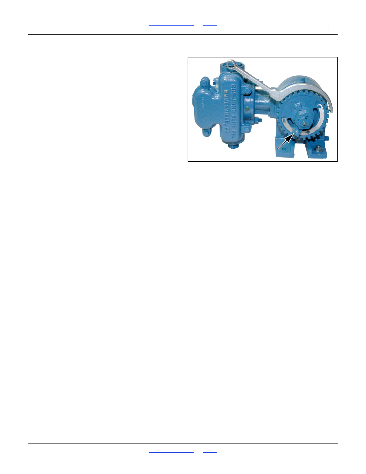
3S-5000/F/HD/HDF Table of Contents Index Adjustments 65
Figure 67
115631-01 Pump Adjuster
Pump Number NGP-6055
31320
There are three adjustments for the liquid fertilizer
system components:
1. Fertilizer Rate:
A fertilizer transmission sprocket pairing (Figure 66)
selects one of two rate Ranges.
An adjuster at the pump (Figure 67) provides fine
control of flow rate. Fertilizer rate is unaffected by
seed rate or ground speed.
See the Seed and Fertilizer Rate manual 195-325B
for charts and detailed setting instructions.
2017-10-26 Table of Contents Index 195-325M
Page 70
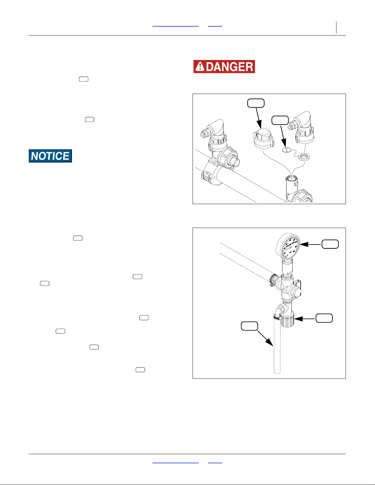
3S-5000/F/HD/HDF Table of Contents Index Adjustments 66
Figure 68
Fertilizer Drop Line Nozzle
29984
L33
L27
Agricultural Chemical Hazard:
Wear protective gloves when exchanging orifice plates.
L27
L33
Figure 69
Fertilizer Relief Valve
31017
L22
L23
L24
L23
L22
L24
L24
L23
L24
L23
Refer to Figure 68
2. Row orifice setup:
Orifice plate sizes are chosen to assure
consistent pressure at all nozzles, wi th the 15-40 psi
range. See the Seed and Fertilizer Rate manual for
sizing and installation.
Unused rows may be shut off by exchanging the
nozzle for a cap . Plates at th e active lin e usually
need to be changed at shut-off or turn-on. See the
Seed and Fertilizer Rate manual 195-325B for
details.
Material Loss or Misapplication Risks:
Orifice size must be appropriate for rate selected. Drop line
orifice plates do not affect rate. If orifice size is too small,
over-pressure in system may result in material loss at relief
valve. An orifice size too large may result in uneven
application across all rows.
When shutting off rows, review orifice sizing.
Refer to Figure 69
3. Relief valve setting:
See the Seed and Fertilizer Rate manual for details
on setting this valve.
Once set for a given fertilizer density, the valve only
requires seasonal review.
During operations, monitor the gauge and the dump
line . Watch for the following conditions:
• A reading below 15 psi usually indicates a need for a
smaller orifice size.
• A reading in the ideal 15-40 psi range, but with
material appearing at the dump line , indicates a
need to increase the operating pressure of the
valve .
• A reading at or near 65 psi, with material appearing
at the dump line , usually indicates a need to
increase orifice size (or plugged orifices).
• A reading above 65 psi indicates a need to reduce
the operating pressure of the valve .
2017-10-26 Table of Contents Index 195-325M
Page 71
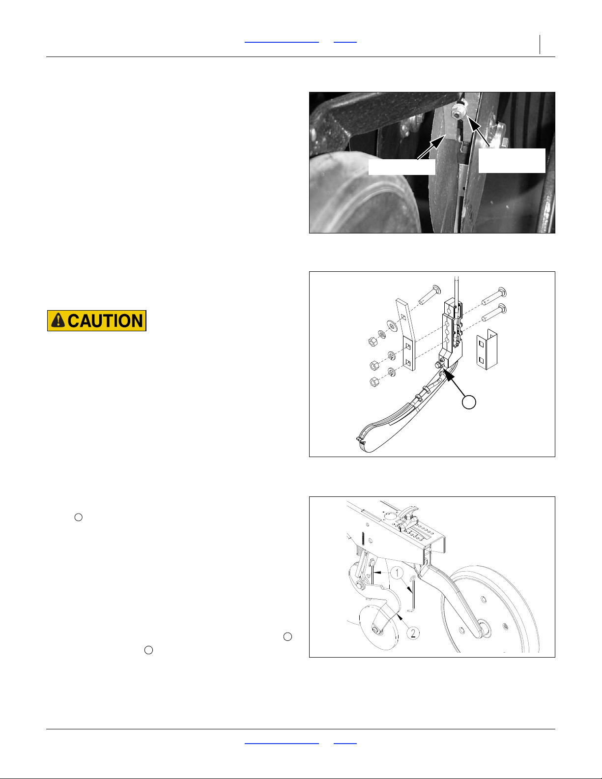
3S-5000/F/HD/HDF Table of Contents Index Adjustments 67
Figure 70
Disk Scraper Adjustment
18842
Disk Scraper
Adjustment Bolt
Figure 71
Keeton
®
Seed Firmer
26390
1
Figure 72
Seed-Lok
®
Lock up
18944
1
1
2
00 Series Disk Scraper Adjustment
Refer to Figure 70
To keep opener disks turning freely, dirt scrapers are
mounted between disks to clean as the disks rotate. As
field conditions vary, you may need to adjust scrapers. In
damp conditions, lower scrapers. If openers are not
turning freely, raise scrapers.
To adjust, loosen
3
/8inch bolt, shown in, and move
scraper as needed.
Seed Firmer Adjustments
Depending on row option originally specified, 00 Series
row units include a seed flap or Seed-Lok
Keeton
®
seed firmer may be ordered separately.
The seed flap requires no adjustment, but may need to
be replaced if worn, and may need to be shortened if an
optional seed firmer is added after initial delivery.
®
. An optional
Sharp Object Hazard:
Use caution when making adjustments in this area. Row unit
disc blades may be sharp. To adjust the Keeton
®
Seed Firmer,
lower the drill until the discs of the row units are resting on the
ground.
Keeton® Seed Firmer Adjustment
Refer to Figure 71
The optional Keeton
®
Seed Firmer is an engineered
polymer shape that slides down the seed trench. It traps
seeds as they exit the seed tube and firms them into the
bottom of the furrow “V”.
The Firmer is provided with a preset tension which is
recommended for using the first year. The tension
screw can be tightened in subsequent years according
to your needs. Firmers should provide just enough
tension to push seeds to the bottom of the trench.
00 Series Seed-Lok® Lock Up
Optional Seed-Lok® firming wheels provide additional
seed-to-soil contact. The wheels are spring loaded and
do not require adjusting. In some wet and sticky
conditions the wheels may accumulate soil.
Refer to Figure 72
To lock up Seed-Lok
under Seed-Lok
®
wheels, hook bottom of hanger
®
arm as shown
2017-10-26 Table of Contents Index 195-325M
Page 72
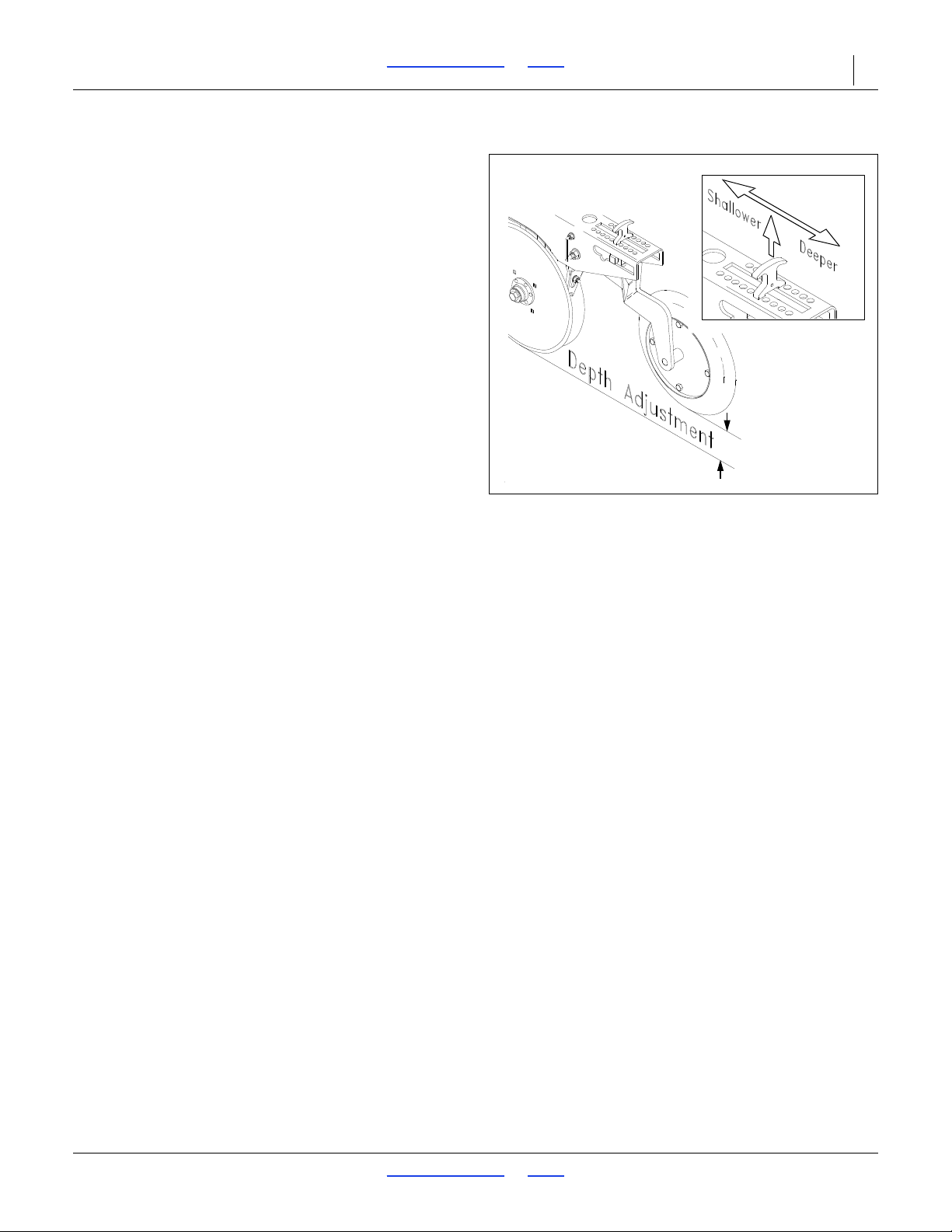
3S-5000/F/HD/HDF Table of Contents Index Adjustments 68
Figure 73
Press Wheel Adjustment
15659
00 & 00HD Series Opener Depth
Press Wheel Adjustment
A press wheel is attached to each opener body. Press
wheels provide two important functions.
First, press wheels close seed furrow s and gently press
soil over seed. To provide consistent seed firming, press
wheels are free to move down from normal operating
position. This maintains pressing action even if opener
disks encounter obstructions or hard soil.
Second, press wheels control seeding depth. To
maintain a consistent depth, the relationship between the
bottom of the opener disks and press wheel is fixed
upwardly by an adjustable stop on each opener. The
position of the adjustable stop determines how deep
seed is placed. Raising the stop increases seeding
depth. Lowering the stop decreases seeding depth.
Refer to Figure 73
Set opener seeding depth by adjusting press-wheel
height. To adjust, first rais e openers slightly, then lift and
slide T-handles on top of openers. Adjust all press
wheels to the same height.
• For shallower seeding, slide T-handles toward drill.
• For deeper seeding, slide T-handles away from drill.
NOTE:
Opener down pressure controls soil-firming pressure
on press wheel. Use press-wheel adjustments to
regulate seeding depth and opener-down-pressure
adjustments to control opener penetration and soil
firming.
2017-10-26 Table of Contents Index 195-325M
Page 73
3S-5000/F/HD/HDF Table of Contents Index Troubleshooting 69
Troubleshooting
Problem Cause Solution
Planting too much
Planting too little
Uneven seed
spacing.
Incorrect seed rate or drive type. Check seed rate information in Seed Rate manual.
Seed size and weight may vary. Adjust seed rate handle.
Actual field size is different. Verify field size.
Excessive overlap.
Irregular shaped field.
Incorrect tire size or air pressure. Correct tire size and air pressure, page 96.
Seed cup door open too much. Refer to page 52.
Incorrect seed rate or drive type. Check seed rate information in Seed Rate manual.
Excessive field speed. Reduce field speed.
Seed size and weight may vary. Adjust seed rate handle.
Incorrect tire size or air pressure. Correct tire size and air pressure, page 96.
Check seed level in seed box. Fill seed box.
Actual field size is different Verify field size.
Excessive gaps between drill passes Adjust marker, page 68.
Build up of seed treatment in seed cups. Clean out seed cups.
Plugged opener seed tube. Lift drill, expose bottom of seed tube and clean out.
Obstruction in seed cup from foreign
matter or unclean seed.
Thrown or worn drive chains Check drive chains.
Worn sprockets and/or chain idlers. Replace sprockets and/or chain idlers
Excessive field speed. Reduce field speed
Unclean seed. Use clean seed.
Build up of seed treatment in seed cup. Clean out seed cup.
Adjust marker, page 68.
Clean seed cup.
Seed-Lok® plugging. Lock up Seed-Lok®, page 67.
Damaged or missing seed flap. Replace seed flap.
Opener disks not turning.
Plugged opener seed tube. Lift up drill, expose bottom of seed tube and clean out.
Worn/rusted sprockets and/or chain idler.
Opener not penetrating low spots. Adjust opener, see instructions beginning on page 57.
Drive type too slow. Use faster drive type and readjust seed rate handle.
Seed cup flutes are open too far. Close flutes to a more narrow position.
Uneven seed depth
2017-10-26 Table of Contents Index 195-325M
Excessive field speed. Reduce field speed.
Planting conditions too wet. Wait until drier weather.
Seed-Lok® building up with dirt. Lock up Seed-Lok®, page 67.
Damaged or missing seed flaps. Replace seed flaps.
Partially plugged opener seed tube. Lift up drill, expose bottom of seed tube and clean out.
See “Opener disks not turning freely” in this
Troubleshooting chart.
Check and replace any worn/rusted sprockets or chain
idlers.
Page 74
3S-5000/F/HD/HDF Table of Contents Index Troubleshooting 70
Problem Cause Solution
Opener disks not
turning freely
Acremeter does not
measure accurately
NOTE:
Acremeter is most
accurate when
seeding back and
forth with markers
Opener plugged with dirt. Clean opener.
Planting conditions too wet. Wait until drier weather.
Seed-Lok® is plugging opener. Lock up Seed-Lok®, page 67.
Failed disk bearings. Replace disk bearings.
Bent or twisted opener frame. Replace opener frame.
Partially plugged opener seed tube. Lift up drill, expose bottom of seed tube and clean out.
Incorrect tire size or air pressure. Correct tire size or air pressure, page 96.
Excessive overlap or gaps between
passes.
Soil conditions.
Acremeter not for your width of drill. Refer to drill parts manual.
Avoid overlap or gaps. Adjust marker.
Loose soil and slippage will cause variations in acres
registered.
with few
headlands,
curves and point
Actual field size different. Verify field size.
rows.
Press wheels not
compacting the soil
as desired
Excessive seed
cracking
Drill boxes do not
empty evenly
Drill boxes do not
empty evenly (cont.)
Press wheel or
openers plugging
Too wet or cloddy. Wait until drier weather or rework ground.
Not enough hydraulic down pressure.
Incorrect press wheel depth. Reset press wheel depth, page 68.
Excessive field speed. Reduce field speed.
Unclean seed. Use clean seed.
Damaged, old or dry seed. Use clean, new seed.
Seed cup flutes not open enough. Open seed cup flutes.
Seed cup door handle not open enough. Refer to page 52.
Drive types not the same on all boxes. Correct drive types.
Opener seed tube plugged.
Drive chains missing or damaged. Replace drive chains.
Planting around fields vs.
back-and-forth.
Rough field conditions may move seed
in the box.
Seed cup(s) are shut off. Open seed cup(s).
Some models do not have the same
number of seed cups between each
bulkhead divider. The section with more
seed cups will empty sooner.
Planting conditions too wet. Wait until drier weather.
Too much hydraulic pressure on
openers.
Backed up with drill in the ground. Clean out and check for damage.
Failed disk bearings. Replace disk bearings.
Disk blades worn. Replace disk blades.
Scraper worn or damaged. Replace scraper.
Increase hydraulic down pressure, see instructions
beginning on page 58.
Lift up drill, expose bottom of seed tube and clean out with
wire.
Correct planting operation.
N/A
Verify number of seed cups in each box.
Reduce hydraulic down pressure on openers.
2017-10-26 Table of Contents Index 195-325M
Page 75
3S-5000/F/HD/HDF Table of Contents Index Troubleshooting 71
Problem Cause Solution
Seed cup sprockets
locked up or seed
drive shaft twisted.
Openers drill too
deep (Bulldozing)
Front of openers
dropping too low in
hard or minimum-till
conditions
Foreign matter lodged in seed cup
sprockets.
Build-up of dried liquid insecticide in
seed cups.
Too much hydraulic down pressure on
openers.
Incorrect press wheel adjustment. Readjust press wheel, page 68.
Incorrect opener frame setting. Set opener frame bolt in top hole, page 54.
Too much hydraulic down pressure on
openers.
Clean out seed cup sprockets.
Remove build-up by disassembling each seed cup and
scraping the foreign substance from turning surfaces.
Reduce hydraulic down pressure on openers.
Reduce hydraulic down pressure on openers.
Openers raise when
tractor hydraulic
lever is held forward
Reverse hydraulic hoses at tractor quick couplers.
and lower when
lever is held back.
Opener frames do
not float over
uneven terrain.
Pressure gauges
read zero when
openers are lowered
and tractor
hydraulic lever is
held forward
Pressure gauges
show pressure
when openers are
raised.
Transpor t lock
channels will not
stay in position for
transport.
Hydraulic lever not locked forward. Lock hydraulic lever forward.
Openers not connected to circuit
designed for hydraulic motor control.
Hydraulic hoses not routed correctly
between pressure control valves and
opener lift cylinders.
Hydraulic hoses not routed correctly
between pressure control valves and
opener lift cylinders.
U-shaped clip in lock channel not
clasping cylinder rod securely.
Hydraulic cylinders have not settled
against lock channels before
transporting.
Refer to page 34.
See hose routing diagrams beginning on page 98.
See hose routing diagrams beginning on page 98.
Tighten or loosen clip by turning bolt on clip. Replace clip if
necessary.
Make sure hydraulic cylinders have settled against lock
channels before transporting. The weight of the cylinders
help hold lock channels in place.
2017-10-26 Table of Contents Index 195-325M
Page 76

3S-5000/F/HD/HDF Table of Contents Index Maintenance and Lubrication 72
Spill hazard/Tank damage risk:
Periodically check the tension of the straps for the fertilizer
tank. Strap tension will change as outside air temperature
changes. Adjust tension as necessary to prevent personal
injury or damage to the fertilizer tank.
Do not use petroleum based products on feeder cup or small
grass cup components.
Maintenance and Lubrication
Maintenance
Proper servicing and maintenance is the key to long
implement life. With careful and systematic inspection,
you can avoid costly maintenance, downtime, and repair.
Always turn off and remove the tractor key before
making any adjustments or performing any maintenance.
Crushing Hazard:
Always have transport locks in place and frame sufficiently
blocked up when working on implement. You may be severely
injured or killed by being crushed under the falling implement.
High Pressure Fluid Hazard:
Check all hydraulic lines and fittings before applying pr essure.
Fluid escaping from a very small hole can be almost invisible.
Use paper or cardboard, not body parts, and wear heavy
gloves to check for suspected leaks. Escaping fluid under
pressure can have sufficient pressure to penetrate the skin. If
an accident occurs, seek immediate medical assistance from a
physician familiar with this type of injury.
This drill has a negative tongue weight when unfolded and
openers are raised. Lower parking stand, lower openers and
remove hydraulic down pressure bef ore unhitching the drill in
the unfolded position. Unhitching in the unfolded position with
openers raised could result in sudden elevation of the tongue,
causing injury or death.
1. After using your drill for several hours, check all bolts
to be sure they are tight.
2. Remove excess slack from chains. Clean and use
chain lube on all roller chains as needed.
3. Maintain proper air pressure in drill tires.
4. Keep disk scrapers properly adjuste d.
5. Clean drill on a regular basis. Regular and thorough
cleaning will lengthen equipment life and reduce
maintenance and repair.
6. Lubricate areas listed under “Lubrication” on
page 83.
7. Replace any worn, damaged, or illegible safety
labels by obtaining new labels from your Great
Plains dealer.
2017-10-26 Table of Contents Index 195-325M
Page 77
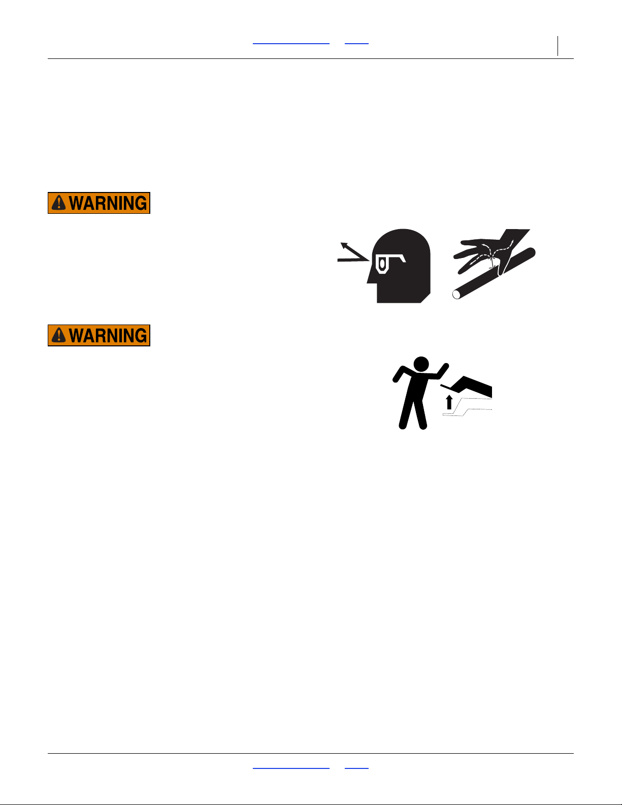
3S-5000/F/HD/HDF Table of Contents Index Maintenance and Lubrication 73
Bleeding Hydraulics
To function properly, the hydraulics must be free of air. If
hydraulics have not been bled, they will operate with
jerky, uneven motions and could cause wings to drop
rapidly during folding or unfolding. If hydraulics were not
bled during initial implement setup or if you replace a par t
in hydraulic system during the life of the drill, complete
the following procedures.
High Pressure Fluid Hazard:
Relieve pressure before disconnecting hydraulic lines.
Escaping fluid under pressure can have sufficient pressure to
penetrate the skin causing serious injury. Use a piece of paper
or cardboard, NOT BODY PARTS, to check for leaks. Wear
protective gloves and safety glasses or goggles when working
with hydraulic systems. If an accident occurs, seek immediate
medical attention from a physician familiar with this type of
injury.
Negative Tongue Weight Hazard:
Raising openers on unfolded, unhitched drill will cause drill
tongue to rise suddenly, which could cause serious injury or
death. Be certain that drill is hitched securely to your tractor
drawbar and the safety chain is securely attached to tractor
before raising openers and unfolding drill.
2017-10-26 Table of Contents Index 195-325M
Page 78
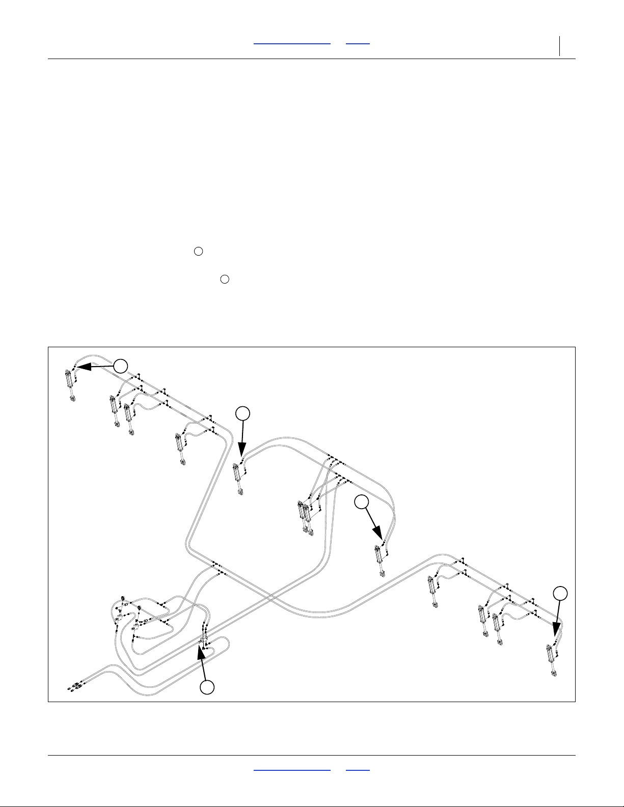
3S-5000/F/HD/HDF Table of Contents Index Maintenance and Lubrication 74
Figure 74
Bleeding Opener Lift Hydraulics
34348
1
2
2
2
2
1
2
Bleeding Opener Lift Hydraulics
Refer to Figure 74
1. Check hydraulic fluid level in tractor re servoir and fill
to proper level. Add fluid to system as needed.
System capacity for entire drill is about
1
4
/2gallons (17 liters).
2. Make sure opener frames are locked up in road
position. See “Opener Lock Up” on page 37.
3. Turn knob on both pressure-control valves
completely counterclockwise, then turn valves
clockwise far enough to build up 1000 psi (about
three turns).
4. Turn knob on bypass valve completely clockwise
for no oil flow.
5. Loosen four top hose-end fittings at the locations
shown.
NOTE:
Do not loosen an O-ring fitting for bleeding. Bleeding
air from an O-ring fitting will damage the seal.
6. Slowly supply oil to top side of pressure-control
valves until oil begins to appear at a loosened hose
fitting. As oil begins to appear at a fitting, tighten that
fitting.
7. Slowly supply oil to bottom s ide of pressure-control
valves until oil begins to appear at remaining
loosened hose fitting. As oil begins to appear at the
fitting, tighten fitting. Continue to supply oil to bottom
side of pressure-control valves until all openers are
raised completely.
8. Move opener transport locks to field position and
cycle openers up and down ten times. Each time you
lower openers, hold tractor remote lever until opener
circuit builds up to pressure set at control valves.
9. After cycling openers, return opener transport locks
to road position.
2017-10-26 Table of Contents Index 195-325M
Page 79
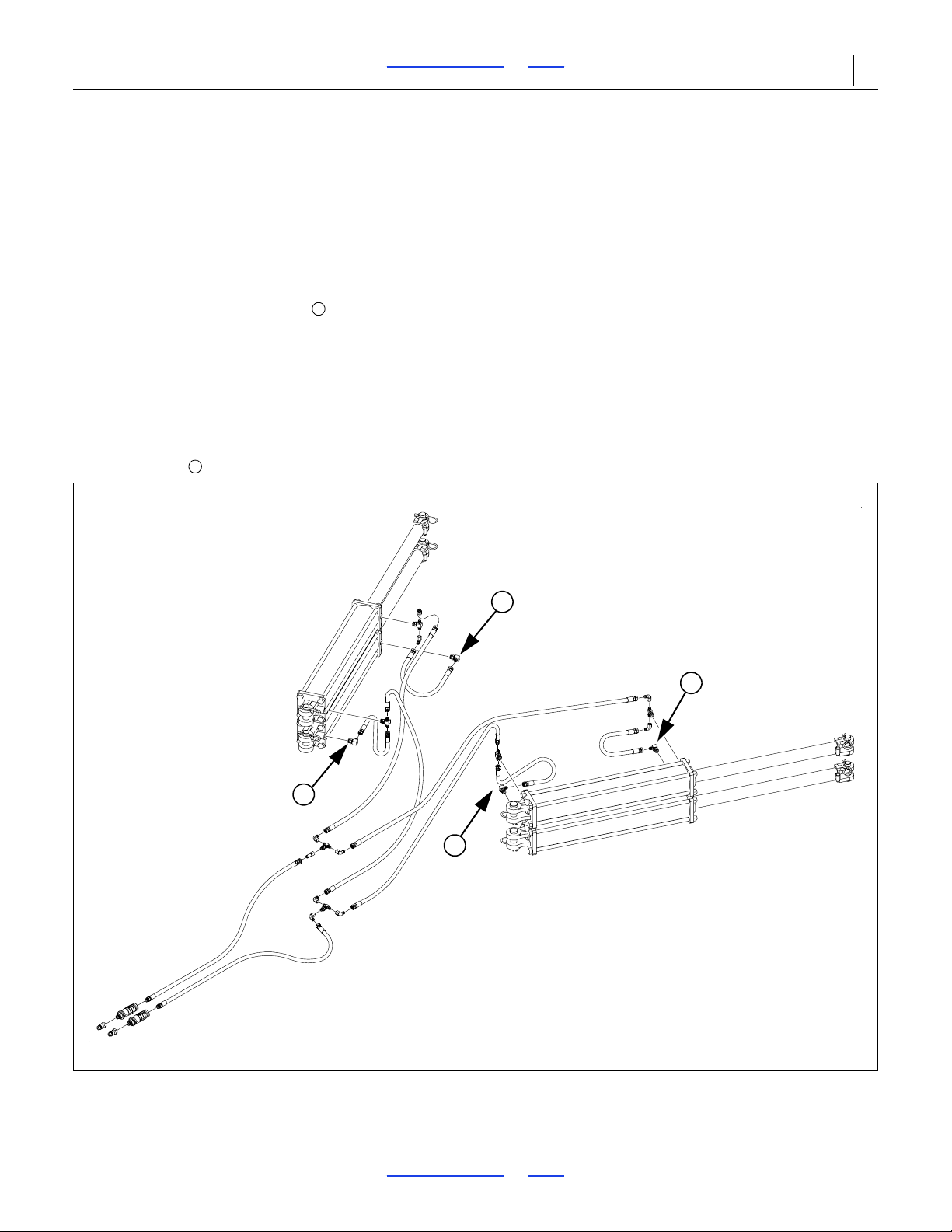
3S-5000/F/HD/HDF Table of Contents Index Maintenance and Lubrication 75
Figure 75
Bleeding Fold Hydraulics
34342
1
2
1
2
1
2
Bleeding Fold Hydraulics
Refer to Figure 75
1. Check hydraulic fluid level in tractor re servoir and fill
to proper level. Add fluid to system as needed.
2. With drill unfolded and fold cylinders completely
extended, disconnect rod end pins and swing the
cylinders so they will not contact anything when
extended.
3. Loosen rod end hose fittings at elbow on lower
fold cylinders.
Do not loosen an O-ring fitting for bleeding. Bleeding
air from an O-ring fitting will damage the seal.
4. Slowly supply oil to rod end of fold cylinders until oil
appears at loosened hose fitting. Tighten fitting and
completely retract fold cylinders.
5. With cylinders completely retracted, loosen base end
hose fittings at elbow on lower fold cylinders.
6. Slowly supply oil to base end of fold cylinders until oil
appears at loosened hose fitting. Tighten base end
hose fitting and cycle fold cylinders in and out
several times.
7. Re-pin cylinder rod clevis.
2017-10-26 Table of Contents Index 195-325M
Page 80

3S-5000/F/HD/HDF Table of Contents Index Maintenance and Lubrication 76
1
2
Figure 76
Bleeding Transport Lift Hydraulics
18836
Bleeding Transport Lift Hydraulics
Refer to Figure 76
1. Check hydraulic fluid level in tractor re servoir and fill
to proper level. Add fluid to system as needed.
2. Lower drill into field position and completely retract
box lift cylinder at middle of tongue. Loosen base
end hose fitting on left transport lift cylinder and base
end fitting on box lift cylinder .
3. Slowly supply oil to base end of transport lift
cylinders until oil appears at loosened hose fitting.
Oil may not appear at both locations at the same
time. As oil begins to appear at a fitting, tighten that
fitting and proceed until both fittings have been
tightened.
4. Completely extend transport lift cylinders and
immediately lock cylinders up by flipping up cylinder
lock channels on both transport lift cylinders and box
lift cylinder.
Crushing Hazard:
The hydraulics could fail, causing the openers to fall and
crush you. To prevent serious injury or death, always secure
cylinder lock channels over extended transport-lift cylinders
before working under openers.
5. When cylinder lock channels are in place, loosen rod
end hose fitting on left transport lift cylinder and rod
end hose fitting on box lift cylinder .
6. Slowly supply oil to rod end of transport lift cylinders
until oil appears at the loosened hose fittings. As oil
begins to appear at fitting, tighten that fitting and
proceed until all fittings are tightened.
7. Extend transport lift cylinders, and remove the
cylinder lock channels. Completely cycle transpor t lift
hydraulics several times.
2017-10-26 Table of Contents Index 195-325M
Page 81
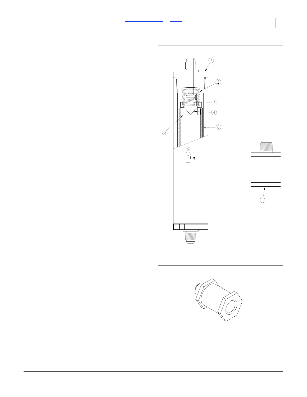
3S-5000/F/HD/HDF Table of Contents Index Maintenance and Lubrication 77
Figure 77
In-line Hydraulic Filters
22984
Figure 78
In-line Hydraulic Filters
25187
Opener Hydraulic Filters
If the raising or lowering times of the opener are
noticeably slower, check the in-line filter and clean if
needed.
Refer to Figure 77
1. To disassemble unscrew end cap of filter. Remove
top retaining washer and screen.
2. Clean filter screen with solvent and compressed air
or replace if needed.
3. When reassembling put screen into filter. Place
retaining washer on top of filter and screw on end
cap.
2017-10-26 Table of Contents Index 195-325M
Page 82
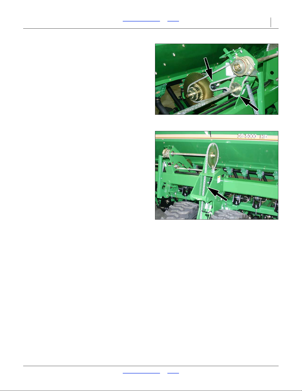
3S-5000/F/HD/HDF Table of Contents Index Maintenance and Lubrication 78
Figure 79
Drive Chains and Idlers
34305
Figure 80
Drive Chains and Idlers
34304
Drive System Maintenance
Refer to Figure 79 and Figure 80
For proper operation and to prevent downtime and
repair, keep drive chains properly adjusted and
lubricated. Regularly check drive chains for excess slack
and wear. Adjust idlers to remove an y excess slack from
chains.
NOTE:
Be sure chain is installed with the chain connector link
retainer towards the centerline and the clip opening
(split end) is facing the opposite way of the chain
travel.
2017-10-26 Table of Contents Index 195-325M
Page 83
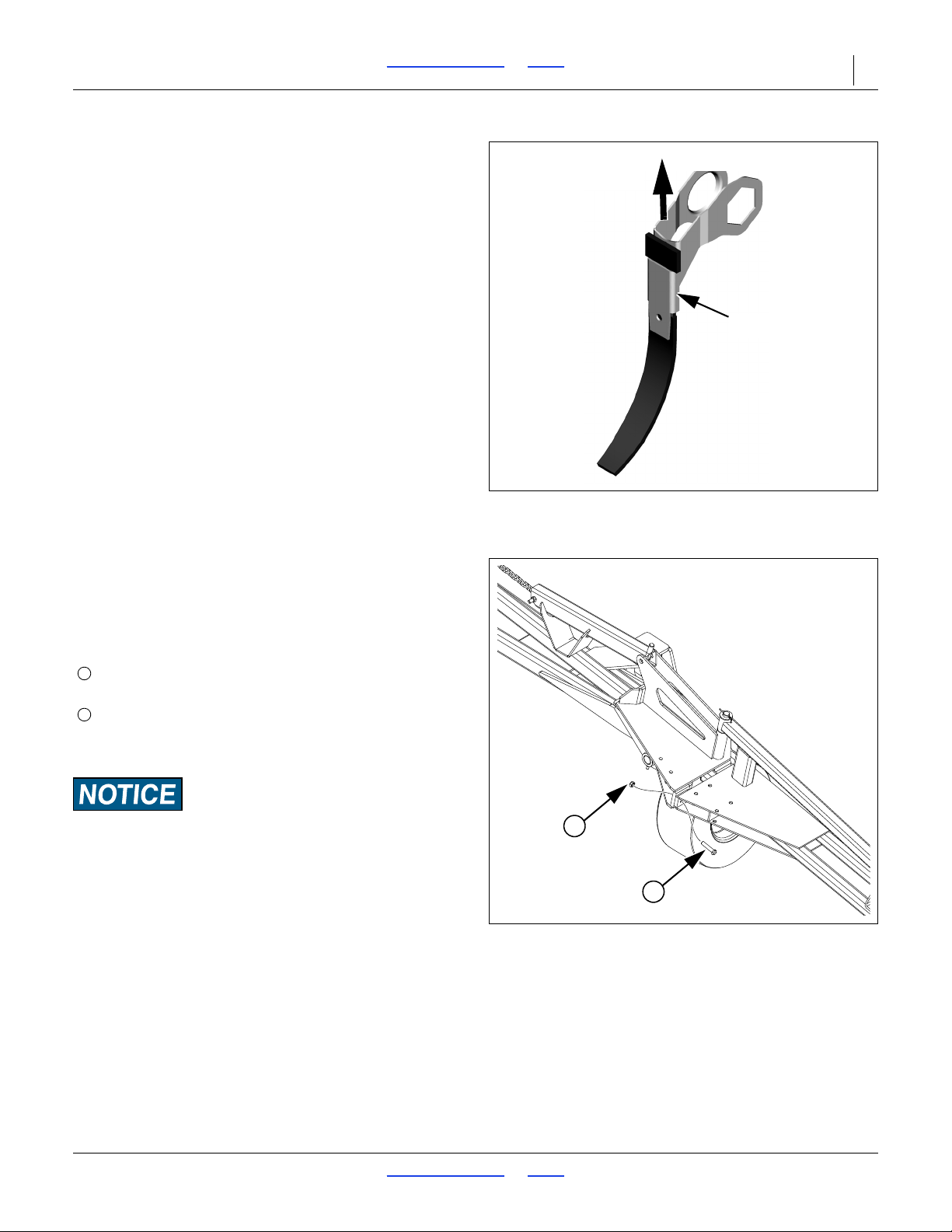
3S-5000/F/HD/HDF Table of Contents Index Maintenance and Lubrication 79
Figure 81
Seed Flap Replacement
18945
Metal Bracket
Pull Up
Figure 82
Marker Shear Bolt
36180
2
1
1
2
Seed Flap Replacement
1. Remove one disk for easier seed flap replacement.
Refer to Figure 81
2. To replace pull the seed flap up out of metal bracket.
3. Push new seed flap down through metal bracket until
seed flap is in place.
Marker Maintenance
If a marker gets caught or hits an obstruction, it is
designed to fail a shear bolt at the fold, pivot on a pin,
and swing back.
The shear bolt is a hex head cap screw,
1
/2-13 x 21/2inch Grade 5,
Great Plains part number 802-130C, plus a
1
/2-13 lock nut, Great Plains part number 803-019C.
Install a replacement shear bolt on the vertical faces on
the side opposite from the pivot bolt.
Equipment Damage Risk:
Using a lower Grade bolt can result in nuisance shears. Using
a higher Grade can result in machine damage.
If grease-seal cap for marker-disk-hub bearings is
damaged or missing, disassemble and clean hub.
Repack with grease and install a new seal or grease cap.
2017-10-26 Table of Contents Index 195-325M
Page 84
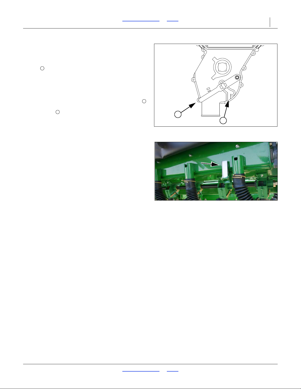
3S-5000/F/HD/HDF Table of Contents Index Maintenance and Lubrication 80
Figure 83
Seed Cup Clean-Out
26211
1
2
1
1
2
Figure 84
A Fertilizer Clean-Out Latch
34320
Materials Clean-Out
Main Box Clean-Out
Refer to Figure 83, which depicts the seed cup door
handle in a normal operating position.
1. Set the Seed Rate Handle to zero (0). This moves
the seed cup sprockets out of the seed path.
2. Position a tarp or bucket under each row or set of
rows to be cleaned out.
3. At the seed cup for that row, pull the door handle
out of the operating detent range, and swing it down
to position .
4. Open the main seed box and use a small brush to
sweep seed toward seed cups set to clean-out. If
seed does not flow freely, inspect seed cup, hose
and seed tubes for obstructions.
5. If a vacuum cleaner is available, use it to remove
residual material.
It is not necessary to operate the meter drive shaft for
clean-out. With the Seed Rate set to zero, nothing
moves inside the seed cups; however, an inspection of
the flutes for excess wear and damage does require
shaft rotation.
Set the Seed Rate Handle to 100 and disengage the
lock-out hub. With openers lowered to engage the clutch,
the seed meter jackshaft can be slowly turned with the
calibration crank, while another person inspects the
flutes from the open seed boxes.
Fertilizer Box Clean-Out
After applying fertilizer, clean the box as soon as
possible. Fertilizers often contain corrosive chemicals.
Refer to Figure 84
With a small scoop or can, remove as much fertilizer as
possible from drill boxes.
Clean-out releases material across the entire length of a
box. Have collection equipment prepared.
Release all clean-out latches on the drill, and open
clean-out door. Leave door open until after washout.
Wash inside of fertilizer box with high pressure water.
Let drill boxes dry before closing clean-out doors.
Small Seeds Box Clean-Out
1. Open box lid and scoop out as much seed as
possible.
2. To recover remaining seed, place a collection tarp
under the small seeds tubes at the openers.
3. Raise drill.
4. Set seed rate handle to 100.
5. Rotate calibration crank or end wheel until no seed
flows.
6. If a vacuum cleaner is available, remove any
residual seed from top of meters.
2017-10-26 Table of Contents Index 195-325M
Page 85
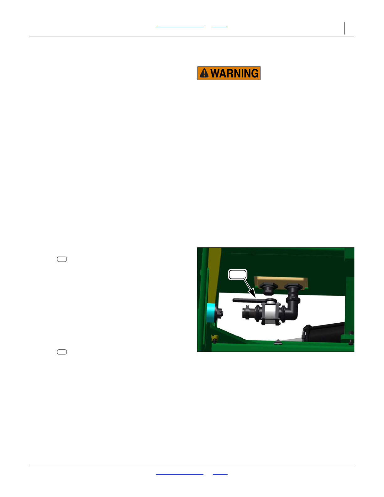
3S-5000/F/HD/HDF Table of Contents Index Maintenance and Lubrication 81
Figure 85
Tank Discharge Line Valve
file
Possible Chemical Hazard:
Wear proper protective equipment as required by chemical
manufacturer. Avoid prolonged breathing of chemical fumes.
Wear respirator as required by chemical manufacturer. Some
chemicals will cause serious burns, lung damage, and death.
Avoid contact with skin or eyes. Seek medical assistance
immediately if accident occurs. Know what to do in case o f an
accident.
L15
L34
L15
Liquid Fertilizer Clean-Out
With proper attention to maintenance, end of day
clean-out, end of season clean-out, and winterizing, you
can substantially increase the life and reliability of your
fertilizer system. Protect the pump, clean the tanks,
strainers, lines and nozzles, and you can avoid costly
and time-consuming repairs at the next season.
Fertilizers are usually highly corrosive to metals other
than stainless steel. Suspension fertilizers can clog
system components in storage.
Flush entire system with clean water. Do this at the field
last treated, or other location compliant with chemical
supplier clean-up instructions.
1. Remove end caps from booms and flush booms out
with water. Drain and replace end caps.
2. Remove strainer and drain it out. Drain all lines and
tank completely to prevent freezing damage.
3. Remove drop line nozzles. Clean orifice plates.
4. Cap or plug inlet line to tractor.
5. Flush pump per pump supplier manual. Fill pump
with RV antifreeze and cap off.
6. Wash all spilled fertilizer off the drill.
Tank Clean-Out
1. If the pump has already been filled with RV
antifreeze for storage, set the main selector
valve to Off or Quick-Fill to prevent draining
pump.
Refer to Figure 85
2. Move the drill to a location suitable for draining
material last applied from the tank, or where the
drainage can be collected. A site with access to rinse
water is ideal.
3. Open the tank lid. Observe the quantity of material
present. Check for build-up, sedimentation and
foreign matter, particularly any objects large enough
to clog the drain.
4. Slowly operate the tank discharge line
valve handle to open the tank to the drain elbow
(“FLOW” legend toward drain elbow).
5. Power-wash the inside of the tank from above.
6. When the tank is clean and drained, set the
discharge valve to Off or Fill/Pump.
7. Close the tank lid.
2017-10-26 Table of Contents Index 195-325M
Page 86
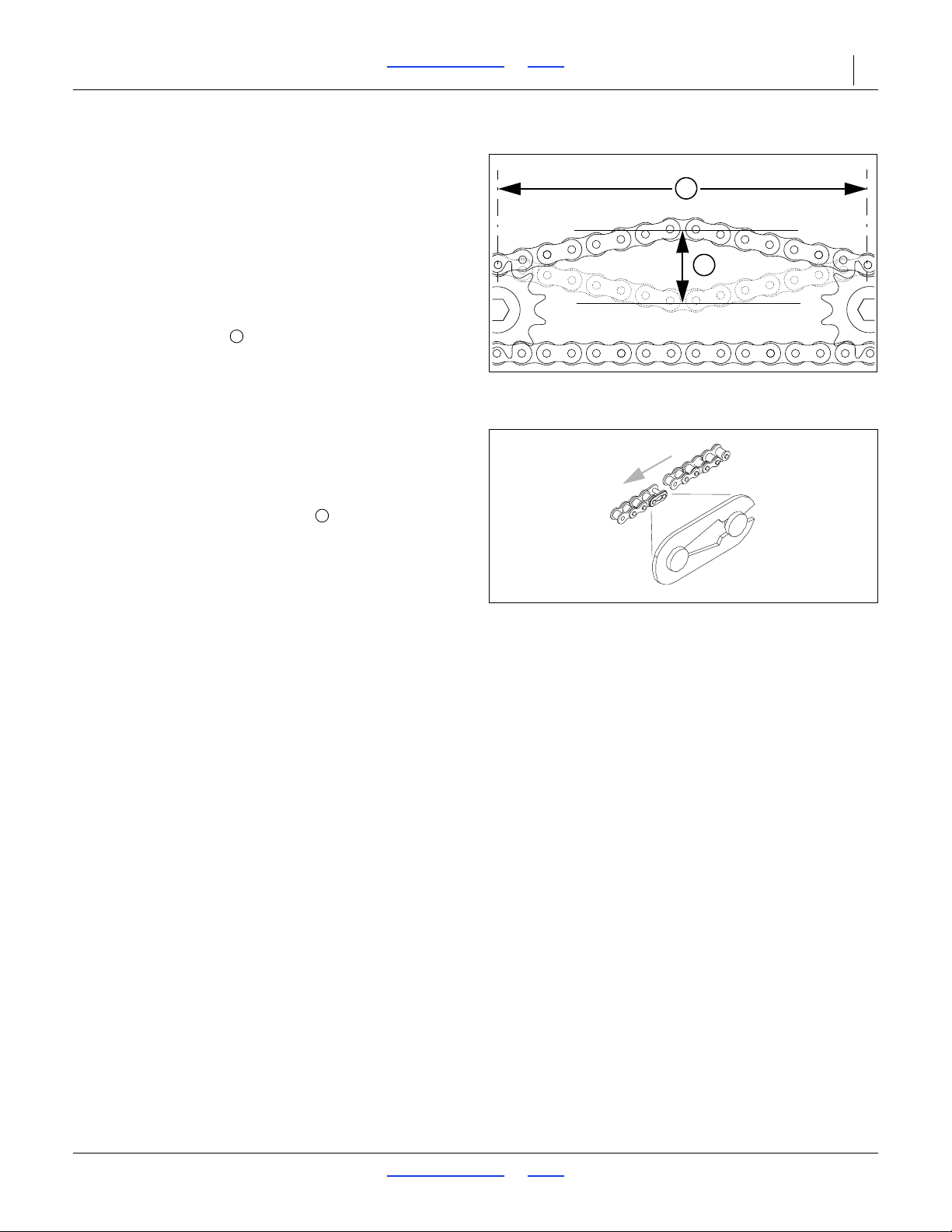
3S-5000/F/HD/HDF Table of Contents Index Maintenance and Lubrication 82
Figure 86
Measuring Chain Slack
27264
2
1
1
Figure 87
Chain Clip Orientation
26482
2
Chain Maintenance
Inspect and lubricate chains regularly. The slack of new
chains tends to increase during the first few hours of
operation due to seating.
Chain Slack
Check slack within the first 8 hours of operation and
tighten idlers as necessary.
Refer to Figure 86, which, for clarity, greatly
exaggerates slack, and omits the idlers.
1. Measure the span for allowable slack:
Locate the longest span of each chain (usually the
span which does not run through the idlers).
2. Measure the current slack:
Acting at a right angle to the chain span at the center
of the span, deflect the chain in both directions with a
force of about 9 lbs (4 kg). The slack is the distance
of the movement.
3. Adjust the idlers for ideal slack .
Whenever mounting a chain, make sure the clip at the
removable link is oriented to minimize snags.
Refer to Figure 87
Install clip with open end facing away from direction of
chain travel (shown by gray arrows in chain routing
diagrams).
2017-10-26 Table of Contents Index 195-325M
Page 87
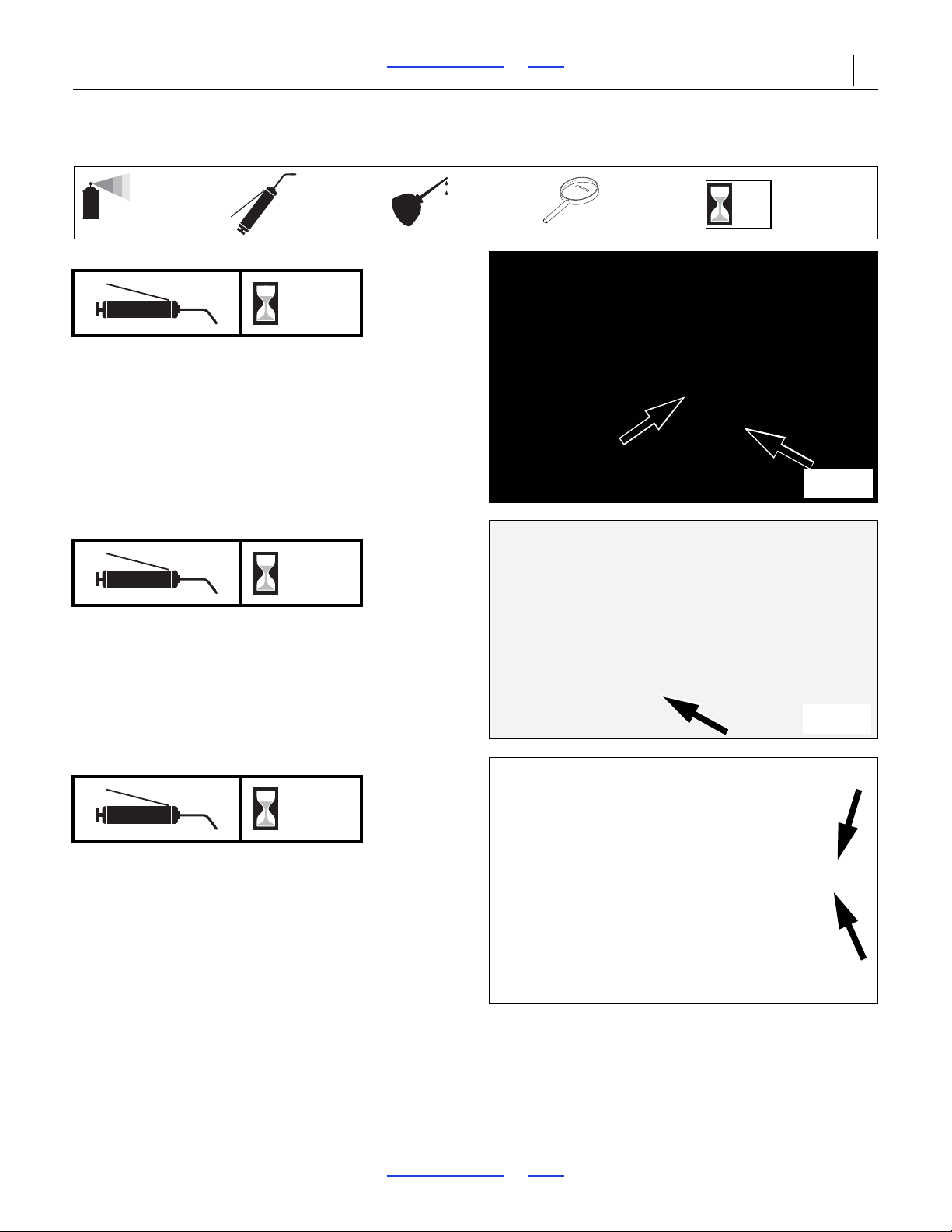
3S-5000/F/HD/HDF Table of Contents Index Maintenance and Lubrication 83
50
Multi-purpose
spray lubricant
Multi-purpose
grease lubricant
Multi-purpose
oil lubricant
Intervals
(operating hours)
at which service
is required
Inspection
34208
18856
18859
18875
Lubrication
Drive Clutches
10
2 grease fittings; on each clutch
Type of Lubrication: Grease
Quantity: Until Grease emerges
Opener Frame Pivots
10
2 grease fittings; center section
1 grease fitting; each wing section
Type of Lubrication: Grease
Quantity: Until Grease emerges from ends of pivot
Telescoping Transfer Drive Shaft
10
2 grease fittings on shaft
Type of Lubrication: Grease
Quantity: Until grease emerges
2017-10-26 Table of Contents Index 195-325M
Page 88
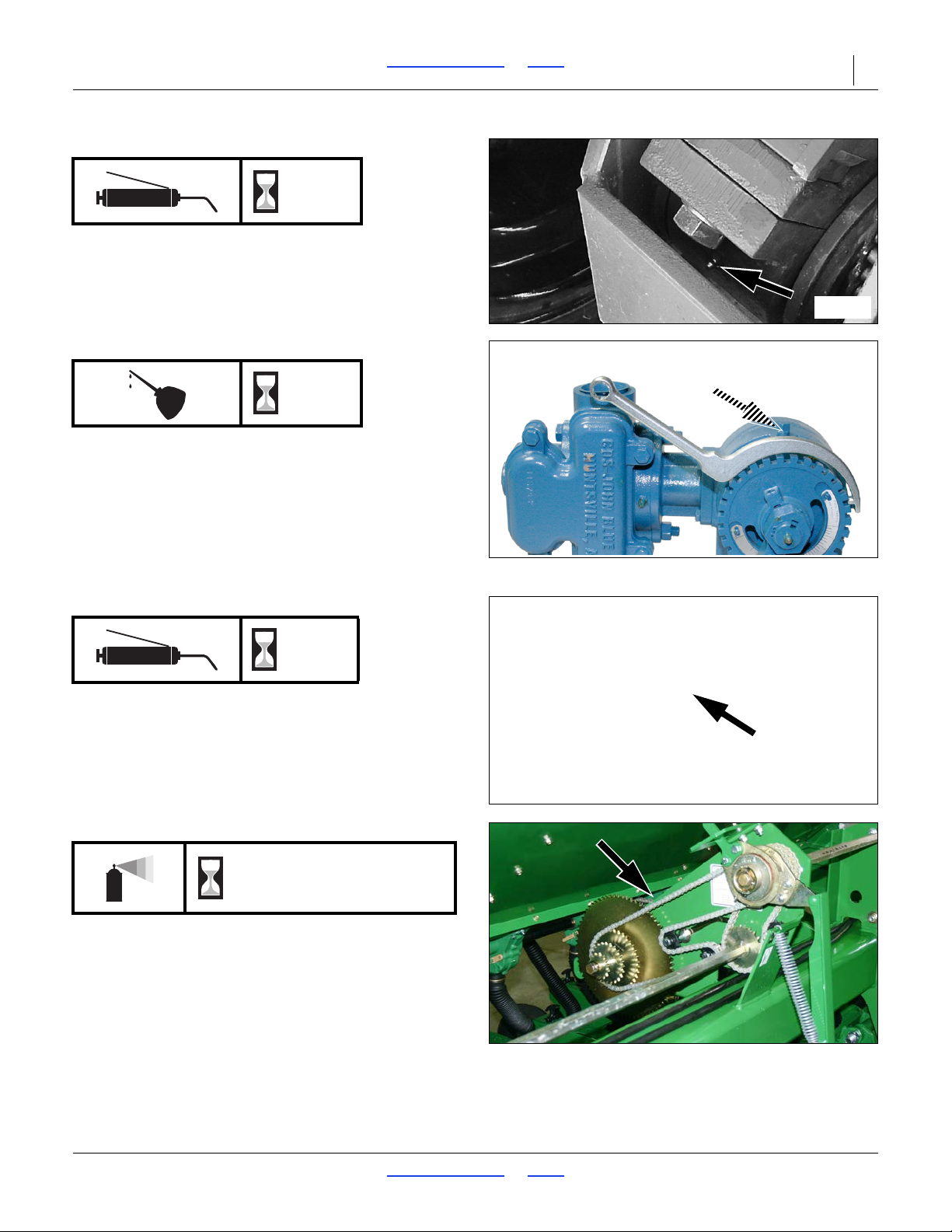
3S-5000/F/HD/HDF Table of Contents Index Maintenance and Lubrication 84
18860
31320
16381
34305
Opener Frame Pivots
10
one each gauge wheel
Type of Lubrication: Grease
Quantity: Until Grease emerges from ends of pivot
Liquid Fertilizer Pump Crankshaft (Option)
10
One inspection/fill port
Type of Lubrication: SAE 90 EP Gear Oil
Quantity: 8 fluid ounce capacity
Refer to JohnBlue manual for pump (NGP-6055)
maintenance.
Null4:
Dry Fertilizer Shaft Bearings (Option)
15
Both ends of shafts; 0 or 6 grease fittings total
Type of Lubrication: Grease
Quantity: Until resistance is felt
Clutch to Speed Change Drive Chain
As Required
One per section
Type of Lubrication: Chain Lube
Quantity = Coat thoroughly
2017-10-26 Table of Contents Index 195-325M
Page 89
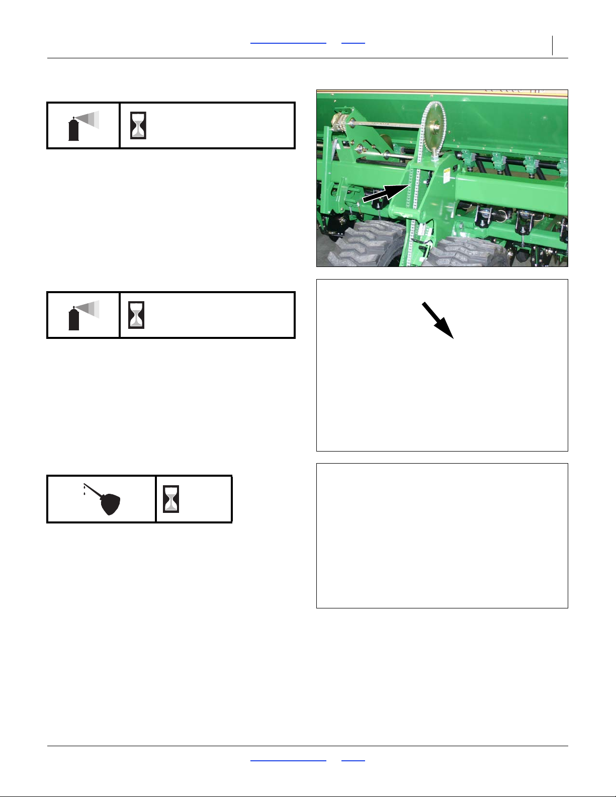
3S-5000/F/HD/HDF Table of Contents Index Maintenance and Lubrication 85
34304
18864
16381
Gauge Wheel to Clutch Shaft Drive Chain
As Required
One per gauge wheel
Type of Lubrication: Chain Lube
Quantity = Coat thoroughly
Speed Change Shaft to Seed Cup Drive Chain
As Required
One per section
Type of Lubrication: Chain Lube
Quantity: Coat thoroughly
Felt Barrier Seals (Option)
2 seals per section, 0 or 6 total
Type of Lubrication: Chain Lube
Quantity = Coat thoroughly
30
2017-10-26 Table of Contents Index 195-325M
Page 90
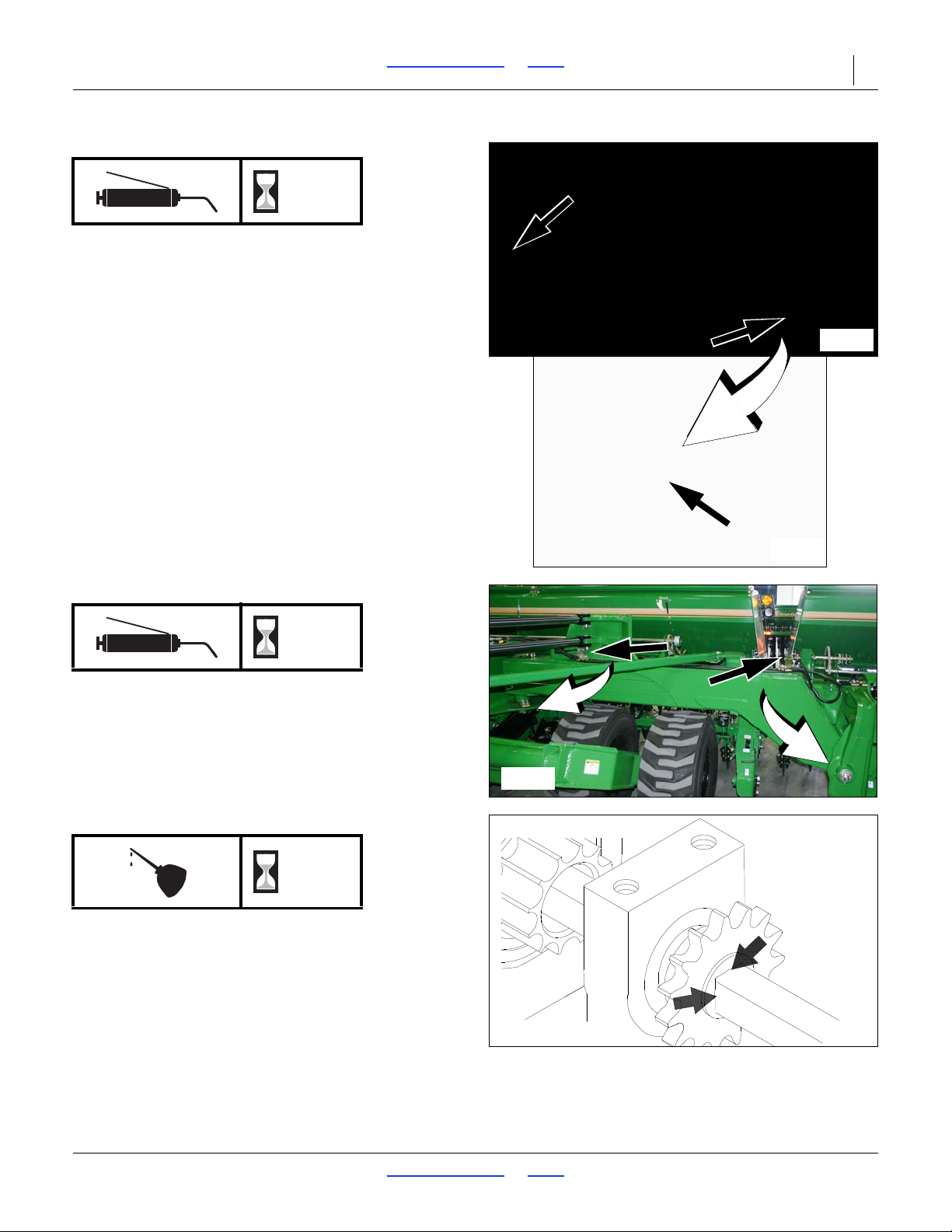
3S-5000/F/HD/HDF Table of Contents Index Maintenance and Lubrication 86
18867
18866
34327
12126
Box Frame Pivots
50
1 grease fitting on each side, 2 grease fittings total
Type of Lubrication: Grease
Quantity: Until grease emerges
Box Frame Pivots
50
1 grease fitting on each side, 2 grease fittings total
Type of Lubrication: Grease
Quantity: Until grease emerges
Seed Cup Drive Sprocket
50
One sprocket per section; 3 total
Type of Lubrication: Oil
Quantity: Coat thoroughly
Move the seed-rate-adjustment handle back and forth
to get oil back into the square bore.
2017-10-26 Table of Contents Index 195-325M
Page 91
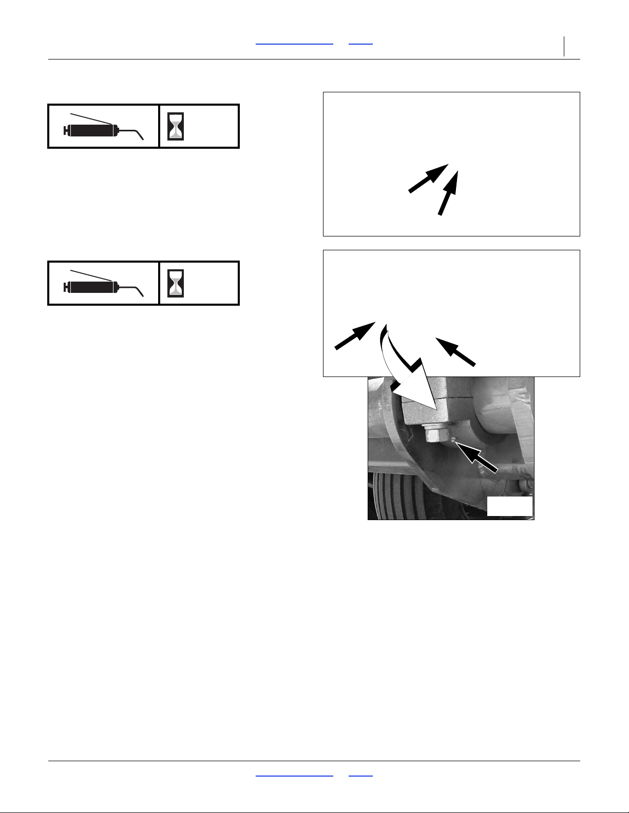
3S-5000/F/HD/HDF Table of Contents Index Maintenance and Lubrication 87
18868
18867
18861
Transport Lift Pivots
50
2 grease fittings
Type of Lubrication: Grease
Quantity: Until Grease emerges
Transport Axle
50
2 grease fittings
Type of Lubrication: Grease
Quantity: Until grease emerges
2017-10-26 Table of Contents Index 195-325M
Page 92
3S-5000/F/HD/HDF Table of Contents Index Maintenance and Lubrication 88
18862
18863
16379
16381
Mainframe Pivots
50
2 grease fittings on each side; 4 grease fittings total
Type of Lubrication: Grease
Quantity: Until grease emerges
Dry Fertilizer Drive Chains (Option)
50
One chain per section; 0 or 3 total
Type of lubrication: Spray
Quantity = Coat chains thoroughly
2017-10-26 Table of Contents Index 195-325M
Page 93
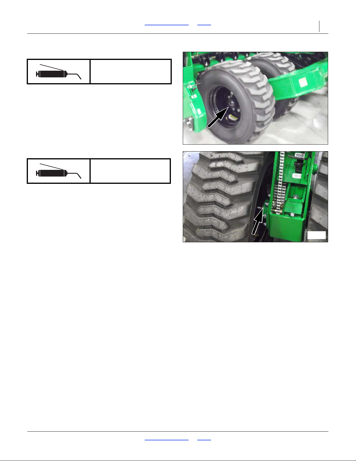
3S-5000/F/HD/HDF Table of Contents Index Maintenance and Lubrication 89
34318
34301
Transport Hub Bearings
2-3 Years
One bearing per tire; 4 total
Type of Lubrication: Wheel Bearing Grease
Quantity: Repack
Gauge Wheel Bearings
2-3 Years
One bearing per tire; 4 total
Type of Lubrication: Wheel Bearing Grease
Quantity: Repack
2017-10-26 Table of Contents Index 195-325M
Page 94
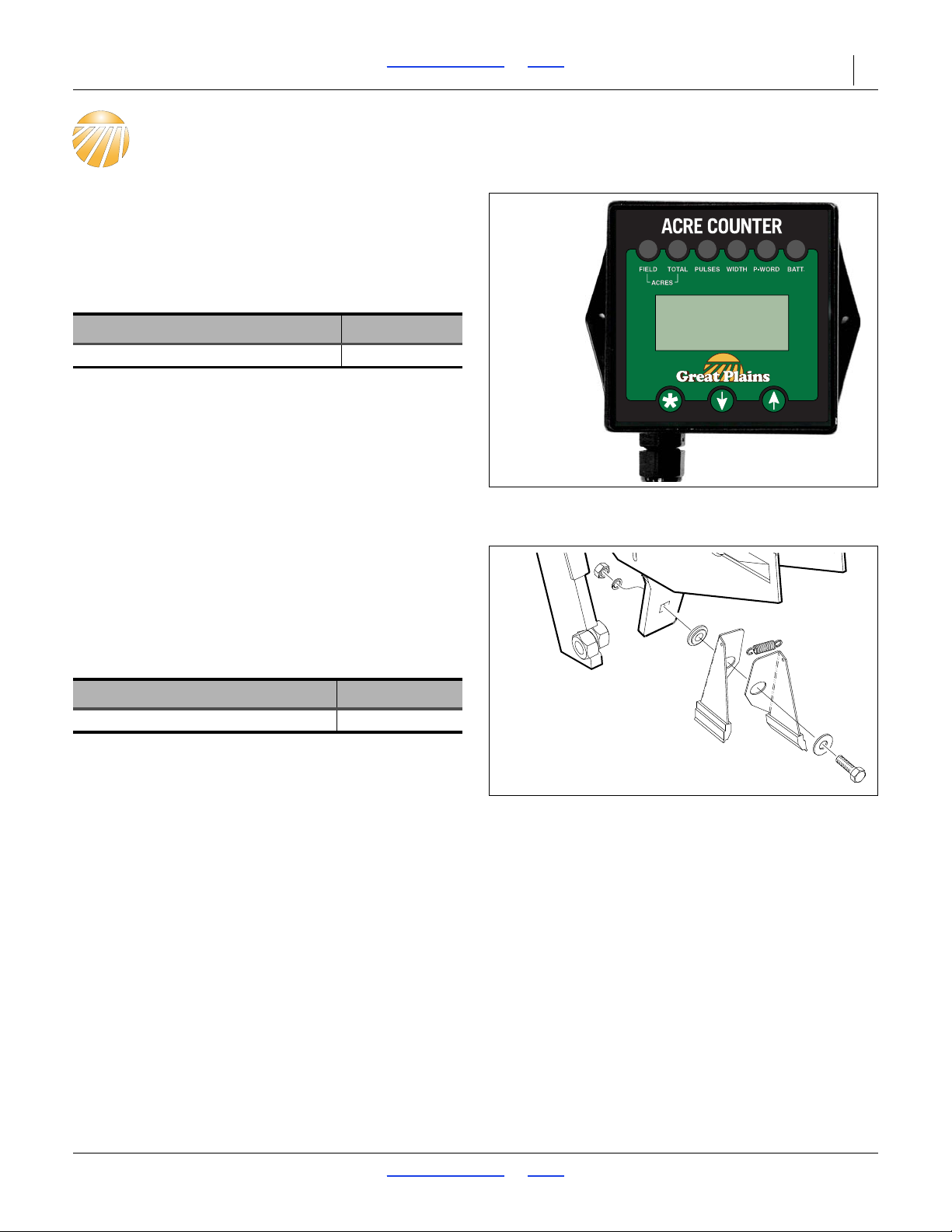
3S-5000/F/HD/HDF Table of Contents Index Options 90
34776
19000
Options
Acremeter
One digital electronic acremeter is standard on the
3S-5000/F/HD/HDF drill. If you require a replacement
order the parts below.
For more information refer to “Acremeter Operation” on
page 48.
Option Packages Part Number
Electronic Acremeter 823-423C
Carbide Disc Scraper
Slotted scrapers are standard.
Optional carbide disc scrapers are spring-loaded and
require no periodic adjus tment. Scrape rs are compat ible
with the standard seed flap and Seed-Lok
Keeton
See “Carbide Disc Scraper Installation” on page 110.
®
.
Description Part Number
SPRING SCRAPER ASSEMBLY 121-781A
®
, but not
2017-10-26 Table of Contents Index 195-325M
Page 95
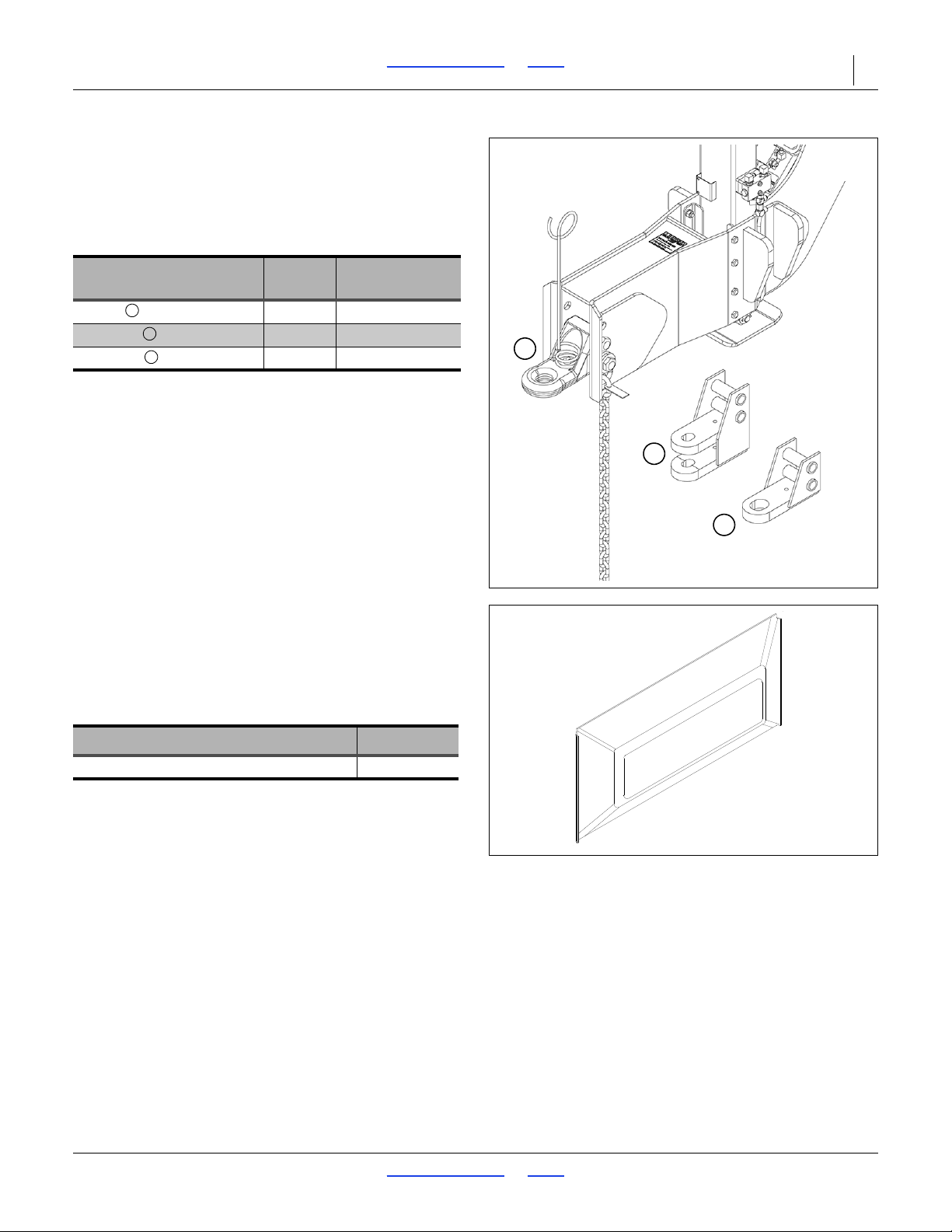
3S-5000/F/HD/HDF Table of Contents Index Options 91
38987
2
1
3
123
16669
Hitches
One hitch is selected upon initial order of an
3S-5000/F/HD/HDF drill, and includes the spring wire
loop, safety chain, and all fasteners. Additional hitches
may be ordered for conversion in the field, and include
extra hitch mounting bolts, lock washers and nuts.
Description
Large Strap (61) 170-038A
Clevis (62) 170-039A
CAT5 (64) 170-073A
Order
Option
Part
Number
Offset Box Divider
The 3S-5000/F/HD/HDF is equipped with standard
dividers that partition the drill boxes into 60 percent seed
and 40 percent fertilizer. Optional offset dividers allow
you to run 68 percent seed and 32 percent fertilizer or
55 percent seed and 45 percent fertilizer.
Description Part Number
Divider Insert 33 X 4.5 Offset 817-322C
2017-10-26 Table of Contents Index 195-325M
Page 96
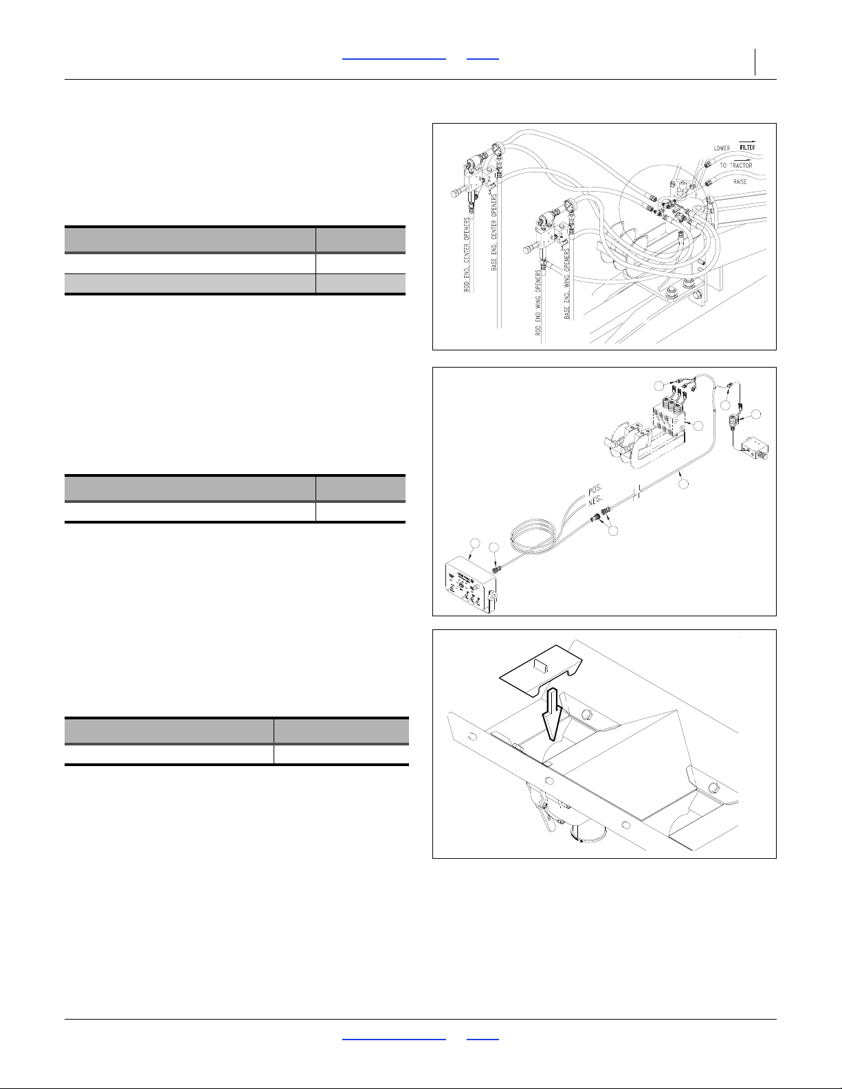
3S-5000/F/HD/HDF Table of Contents Index Options 92
18750
22962
15642
Open Center Conversion Kit
The standard 3S-5000/F/HD/HDF drill is compatible with
tractors having “active” or “closed center” hydraulic
systems. For use with “non-active” or “closed center”
tractors, a conversion kit is available. Order one kit per
drill.
Description Part Number
Open Center Hydraulic Kit 194-143A
Open-Center Hydraulic Assy Manual 194-149M
Point Row Clutch
The 3S-5000/F/HD/HDF can be outfitted with clutches
and controls that allow you to raise and lower openers o n
each drill section independently.
For more information refer to:
“Point Row Operation (Option)” on page 47.
Description Part Number
3S-5000/F/HD/HDF Point Row Accessory 195-306A
Seed Cup Plugs (Main Box)
Seed cup plugs are available to block off individual rows
when a wider row spacing is desired. Plugs are installed
by pushing them into the seed cup openings on desired
rows.
Description Part Number
3
/4 Wide Feeder Cup Plug 817-087C
1
1
3
51
60
67
68
2
70
2017-10-26 Table of Contents Index 195-325M
Page 97
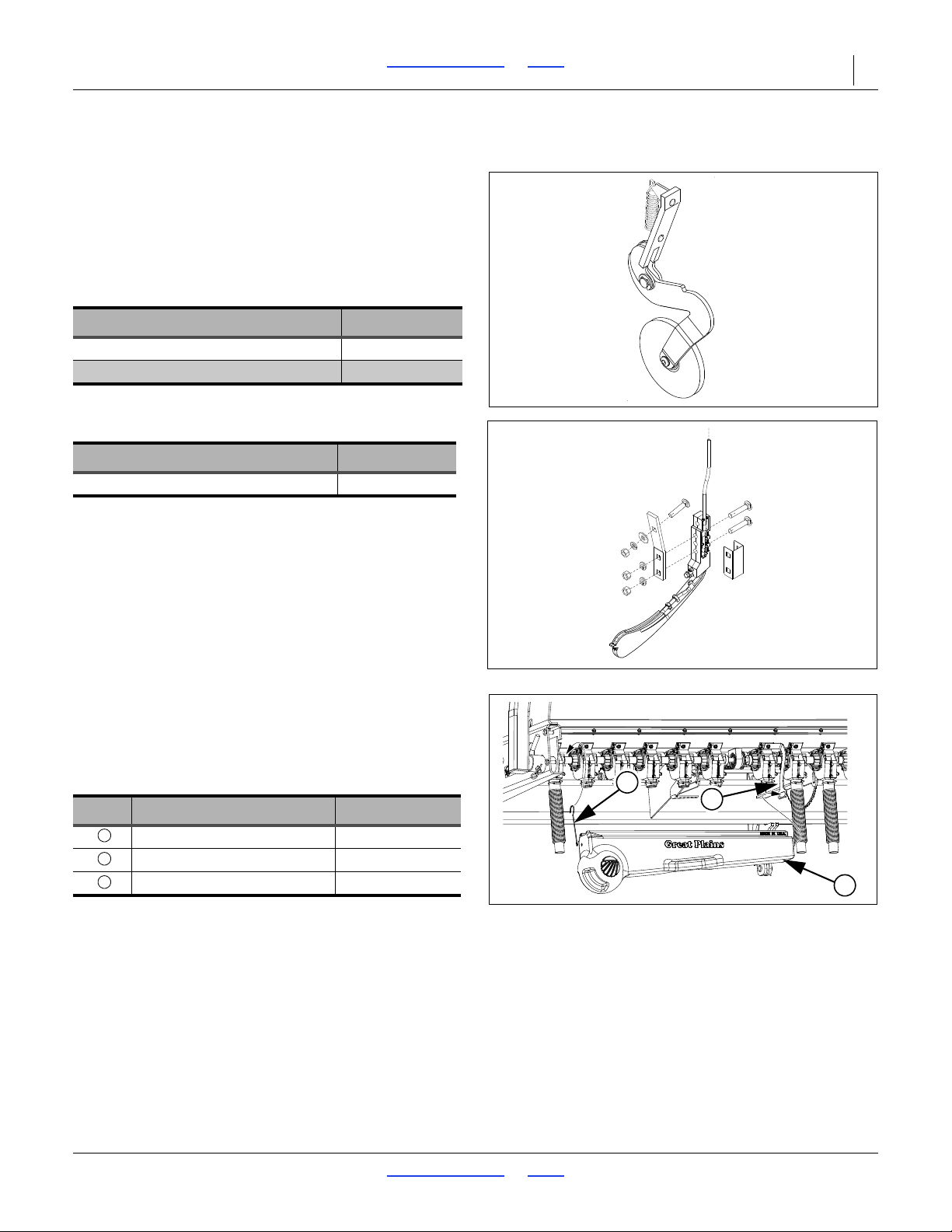
3S-5000/F/HD/HDF Table of Contents Index Options 93
12677
26390
1
2
3
123
Seed Firmers
00 Series Seed-Lok
The spring loaded Seed-Lok® firming wheels press seed
directly into the bottom of the furrow, assuring the best
seed to soil contact. The firming wheels promote even
emergence since seeds are planted and firmed at the
same depth. The wheels bolt directly to the scraper
mount on the standard drill openers.
Option Packages Part Number
00 Series 5 inch Seed-Lok
00 Series 6i inch Seed-Lok
Keeton® Seed Firmer
Description Part Number
®
Keeton
For operations, see “Seed Firmer Adjustments” on
page 67.
seed firmer (per opener) 890-810C
®
Seed Firmer
®
®
122-193K
122-266K
Calibration Tray
This tray is used for calibrating accurate seed rate. It is
necessary to order a spring clip when ordering the tray,
the end mount bracket is already present on newer
models.
Description Part Number
Plastic Calibration Tray 837-013C
Cal Tray End Mount 194-707D
Calibration Tray Spring Clip 807-336C
2017-10-26 Table of Contents Index 195-325M
Page 98
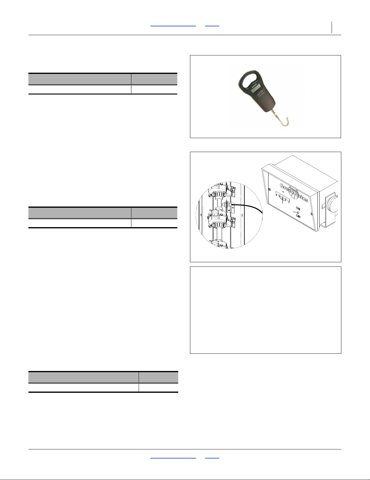
3S-5000/F/HD/HDF Table of Contents Index Options 94
36242
18943
34210
18869
Digital Scale
This scale is for use with the calibration tray.
Option Packages Part Number
Digital Scale 50 LB/23 KG 891-209C
Shaft Monitor
This kit provides a cab alarm in the event that a main box
seed meter shaft stops turn ing (which might result from
excess down-pressure, low tire pressure/flat tire, chain
break or clutch malfunction). Order one kit per drill.
For more information refer to:
“Shaft Monitor Operation (Option)” on page 47.
Option Packages Part Number
3-Channel Shaft Monitor 116-283A
Two Outlet Hydraulic Kit
To operate all drill functions, the standard
3S-5000/F/HD/HDF requires a t ractor with three remote
valves. Tractors with two remote valves can be used with
the two outlet hydraulic kit. Using a double selector valve
mounted on drill tongue, this kit combines transport lift
and opener lift circuits.
To operate a drill equipped with markers on a tractor with
two remote valves, you must install two kits-one to
combine the transport lift and opener lift circu its and one
to combine the marker and fold circuits.
For more information refer to “Hydraulic Hose Hookup”
on page 25 and “Point Row Operation (Option)” on
page 47.
Description Part Number
Two Outlet Tractor Hydraulic Kit 194-122A
2017-10-26 Table of Contents Index 195-325M
Page 99
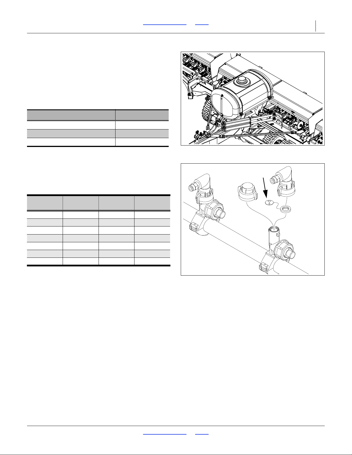
3S-5000/F/HD/HDF Table of Contents Index Options 95
36286
29984
Orifice Part Port Port
Size Number Diameter Area
20 832-052C 0.020 in 0.20 mm²
28* 832-056C 0.028 in
0.40 mm²
34* 832-053C 0.034 in 0.59 mm²
48* 832-054C 0.048 in 1.17 mm²
59 832-057C 0.059 in
1.76 mm²
80 832-055C 0.080 in 3.24 mm²
98 832-059C 0.098 in 4.87 mm²
29993* Sizes standard in many fertilizer bundles.
Check your accessories before ordering.
Liquid Fertilizer System
A liquid fertilizer system includes a support frame, one
tank, drive system (powered by existing ground drive),
strainer, CDS-JohnBlue piston pump, relief
valve/pressure gauge, boom, nozzles, orifice plate sizes
28/34/48, and drop lines to rows.
The system is factory installed, but ordered as a
separate line item.
Description Order Number
3S-5000 Liquid Fert 6 Inch 417-186A
3S-5000 Liquid Fert 7.5 Inch 417-187A
3S-5000 Liquid Fert 10 Inch 417-188A
See “Liquid Fertilizer System (Option)” on page 42.
Fertilizer Orifice Plates
The manifold systems include size 28, 34 and 48 plates.
To order alternate plates, use the following part numbers.
Order one per row unit.
2017-10-26 Table of Contents Index 195-325M
Page 100
3S-5000/F/HD/HDF Table of Contents Index Appendix A - Reference Information 96
Appendix A - Reference Information
Specifications and Capacities
3S-5000-1006 3S-5000-8075 3S-5000-6010
1
Row Spacing 6 inch 7
Rows per Drill 100 80 60
Weight (no fertilizer)
Working Width 50 feet (12.2 m)
Transport Width 15 feet (4.6 m)
Transport Height 8 feet 4 inches (2.5 m)
Transport Length 39 feet 10 inches (12 m)
Field Length 39 feet 10 inches (12 m)
Length, with Liquid Fertilizer 39 feet 10 inches (12 m)
Main Seed Box Capacity 148.7 bushels (5240 li ters)
Small Seeds Box Capacity 10 bushels (352.4 liters)
Liquid Fertilizer Capacity 400 gallons
Gauge Wheel Tires
Transport Wheel Tires
Tractor Requirements
Three remote valves or two remote valves and optional kit.
Tractors with load-sensing hydraulics may require a bypass valve, Great Plains part
number 810-400C. Contact your tractor dealer to verify if the valve is needed.
16.5 NHS Skid Steer
17.5 NHS Skid Steer
240 hp minimum (134 kW)
/2 inch 10 inch
24,260 pounds
11004 kg
30.5 X 12
14 (14 Ply)
Tire Inflation Chart
Tire Inflation Chart Tire Warranty Information
Wheel Tire Size Inflation
Transport
Gauge Wheel
Transport 440/55R18
Gauge Wheel 340/60R16.5
Ground Drive
Wheel, Liquid
Fertilizer
2017-10-26 Table of Contents Index 195-325M
17.5 NHS Skid Steer
16.5 NHS Skid Steer
14
30.5 X 12
7.6-15 6 ply
80 psi
(551 kPa)
44 psi
(303 kPa)
73 psi
(503 kPa)
73 psi
(503 kPa)
73 psi
(503 kPa)
All tires are warranted by the original manufacturer of the tire. Tire
warranty information is found in the brochures included with your
Operator’s and Parts Manuals or online at the manufacturer’s web
sites listed below. For assistance or information, contact your
nearest Authorized Farm Tire Retailer.
Manufacturer Web site
Firestone www.firestoneag.com
Gleason www.gleasonwheel.com
Titan www.titan-intl.com
BKT www.bkt-tires.com/en
 Loading...