

Page 1
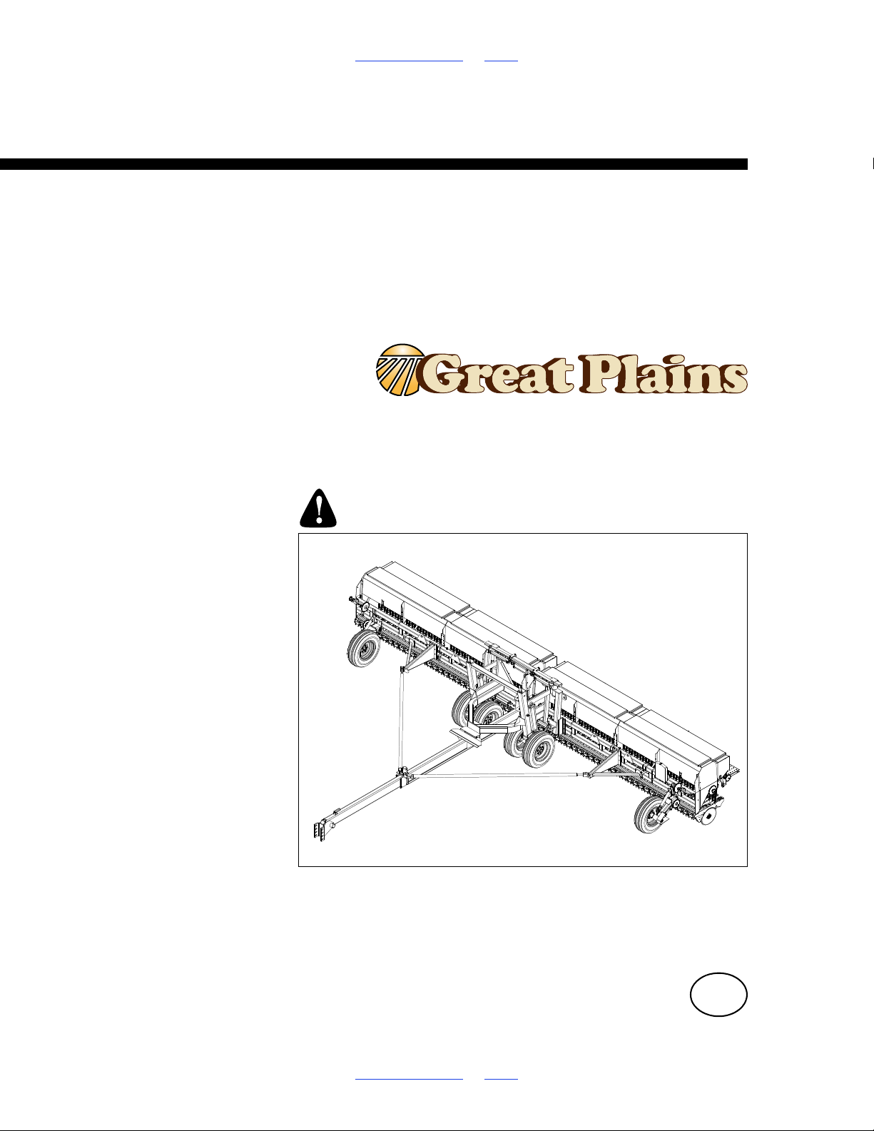
Table of Contents Index
36149
Operator/Rate Manual
2SF24 and 2SF30
Two Section Folding Drill 1994+
Manufacturing, Inc.
www.greatplainsmfg.com
Read the operator manual entirely. When you see this symbol, the
subsequent instructions and warnings are serious - follow without
exception. Your life and the lives of others depend on it!
Illustrations may show optional equipment not supplied with standard unit or
may depict similar models where a topic is identical.
ORIGINAL INSTRUCTIONS
© Copyright 1998 Printed 2018-08-02 155-015M-A
Table of Contents Index
EN
Page 2
Machine Identification
Record your machine details in the log below. If you replace this manual, be sure to transfer this information to the new
manual.
If you or the dealer have added options not originally ordered with the machine, or removed options that were originally
ordered, the weights and measurements are no longer accurate for your machine. Update the record by adding the
machine weight and measurements with the option(s) weight and measurements.
Model Number
Serial Number
Machine Height
Machine Length
Machine Width
Machine Weight
Year of Construction
Delivery Date
First Operation
Accessories
Dealer Contact Information
Name:
Street:
City/State:
Telephone:
Email:
Dealer’s Customer
No.:
WARNING:
Cancer and Reproductive Harm - www.P65Warnings.ca.gov
Page 3

2SF24 and 2SF30 Cover Index iii
Table of Contents
Important Safety Information.................................................1
Safety Decals ....................................................................6
Introduction...........................................................................11
Models Covered ..............................................................11
Description of Unit ...........................................................11
Intended Usage ........................................................11
Document Family.............................................................11
Using This Manual...........................................................11
Definitions.................................................................11
Owner Assistance............................................................12
Further Assistance...........................................................12
Preparation and Setup .........................................................13
Initial Setup......................................................................13
Post-Delivery/Seasonal Setup.........................................13
Pre-Planting Setup ..........................................................13
Hitching Tractor to Drill....................................................14
Tractor Draw Bar Hook-Up.......................................15
Hydraulic Hose Hookup............................................16
Bleeding Hydraulic Systems............................................18
Bleeding the Lifting Hydraulic System ......................18
Bleeding Folding Hydraulics.....................................19
Leveling Drill ....................................................................20
Transport Wheel Adjustments for Leveling Drill .......21
Gauge Wheel Adjustments for Leveling Drill............22
Box Alignment Adjustments.............................................22
Pull Bar Adjustments ................................................22
Drill Adjustments ......................................................23
Operating Instructions .........................................................24
Pre-Start Checklist...........................................................24
General Notes for Field Operations.................................25
Folding the Drill................................................................26
Lifting the Drill..................................................................27
Unfolding the Drill .....................................................28
Transporting the Drill .......................................................29
Parking ............................................................................30
Marker Operations...........................................................31
Dual Marker Operations ...........................................31
Acremeter........................................................................31
DataTrac Acremeter .................................................33
Long-Term Storage .........................................................34
Adjustments ..........................................................................35
Planting Depth Adjustments ............................................36
Press Wheel-Opener Linkage Depth Adjustment ....36
Disk Opener Spring Pressure Setting ......................36
Seeding Adjustments.......................................................37
Main Box Seed Rate Handle ...................................38
Position Seed Cup Doors.........................................38
Seed Rate Charts: U.S. Customary Units .......................39
Alfalfa or Rape .........................................................39
Barley .......................................................................39
Buckwheat................................................................39
Flax or Sudan...........................................................39
Millet.........................................................................40
Milo...........................................................................40
Oats or Safflower .....................................................40
Peas .........................................................................40
Pinto Beans..............................................................41
Rice Long Grain .......................................................41
Rice Short Grain.......................................................41
Rye...........................................................................42
Soybeans .................................................................42
Sunflowers ...............................................................43
Wheat.......................................................................43
Wheat Grass ............................................................44
Small Seeds Attachment .................................................45
Small Grass Seed Charts................................................46
Alfalfa, Red Alsike, Crimson Clover .........................46
Bermuda, Red Top, Lespedeza, Sercia, Sand,
Weeping Love Grass................................................46
Birdsfoot, Trefoil, Sudan...........................................46
Canola, Ladino, Clover, Canary Grass, Timothy...... 46
Red and Sweet Clover, Lespedeza Hulled ..............47
Kentucky Blue Grass, Fescue, Annual Rye Grass...47
Millet, Reed Canary..................................................47
Orchard Grass..........................................................47
Fertilizer Meter Rate........................................................48
Seeding Drive Speeds .............................................48
Fertilizer Rate Charts U.S. Customary Units...................49
Fertilizer 2014+ ........................................................49
Fertilizer 2013- .........................................................49
Density Conversion Chart ........................................49
Fertilizer Sprockets ..................................................49
Marker Adjustments ........................................................50
Folding Speed ..........................................................50
Transport Carrier......................................................51
Marker Chain............................................................52
Marker Disk Adjustment ...........................................52
Disk Scraper Adjustments ...............................................53
Seed Firmer Adjustments................................................53
Troubleshooting ...................................................................55
Maintenance and Lubrication..............................................57
Maintenance....................................................................57
Seed Flap Replacement...........................................58
Marker Maintenance) ...............................................59
Lubrication and Scheduled Maintenance ........................60
© Copyright 1998 All rights Reserved
Great Plains Manufacturing, Inc. provides this publication “as is” without warranty of any kind, either expressed or implied. While every precaution has been
taken in the preparation of this manual, Great Plains Manufacturing, Inc. assumes no responsibility for errors or omissions. Neither is any liability assumed for
damages resulting from the use of the information contained herein. Great Plains Manufacturing, Inc. reserves the right to revise and improve its products as
it sees fit. This publication describes the state of this product at the time of its publication, and may not reflect the product in the future.
Registered Trademarks of Great Plains Manufacturing, Inc. include: Air-Pro, Clear-Shot, Discovator, Great Plains, Land Pride, MeterCone,
Nutri-Pro, Seed-Lok, Solid Stand, Terra-Guard, Turbo-Chisel, Turbo-Chopper, Turbo-Max, Turbo-Till, Ultra-Till, Whirlfilter, and Yield-Pro.
Trademarks of Great Plains Manufacturing, Inc. include: AccuShot, Max-Chisel, Row-Pro,
Singulator Plus, Short Disk, Swath Command, Terra-Tine, Ultra-Chisel, and X-Press.
Brand and Product Names that appear and are owned by others are trademarks of their respective owners.
Printed in the United States of America
2018-08-02 Cover Index 155-015M-A
Page 4

2SF24 and 2SF30 Cover Index iv
Options ..................................................................................62
Appendix A - Reference Information ..................................65
Specifications and Capacities..........................................65
Dimensions Transport .....................................................67
Torque Values Chart .......................................................68
Appendix B - Assembly and Setup .....................................69
Drill Assembly..................................................................69
Assembly Diagram ..........................................................71
Harness Installation (2SF24 S/N 3509F+) (2SF30 S/N
3974G+) ..........................................................................72
Appendix M - Metric Charts .................................................74
Metric Seed Rate Charts .................................................74
Alfalfa or Rape..........................................................74
Barley .......................................................................74
Buckwheat................................................................74
Flax or Sudan ...........................................................74
Millet .........................................................................75
Milo...........................................................................75
Oats or Safflower......................................................75
Peas .........................................................................75
Pinto Beans..............................................................76
Rice Long Grain .......................................................76
Rice Short Grain.......................................................76
Rye...........................................................................77
Soybeans .................................................................77
Sunflowers ...............................................................78
Wheat.......................................................................78
Wheat Grass ............................................................79
Metric Small Grass Seed Charts .....................................80
Alfalfa, Red Alsike, Crimson Clover .........................80
Bermuda, Red Top, Unhulled Lespedeza, Sercia,
Sand & Weeping Love Grass...................................80
Birdsfoot, Trefoil, Sudan...........................................80
Canola, Ladino Clover, Canary Grass, Timothy.......80
Red & Sweet Clover, lespedeza Hulled ...................81
Kentucky Blue Grass, Fescue, Annual Rye Grass...81
Millet, Reed Canary..................................................81
Orchard Grass..........................................................81
Metric Fertilizer Rate Charts............................................82
Fertilizer 2014+ ........................................................82
Fertilizer 2013- .........................................................82
2018-08-02 Cover Index 155-015M-A
Page 5
2SF24 and 2SF30 Table of Contents Index 1
Important Safety Information
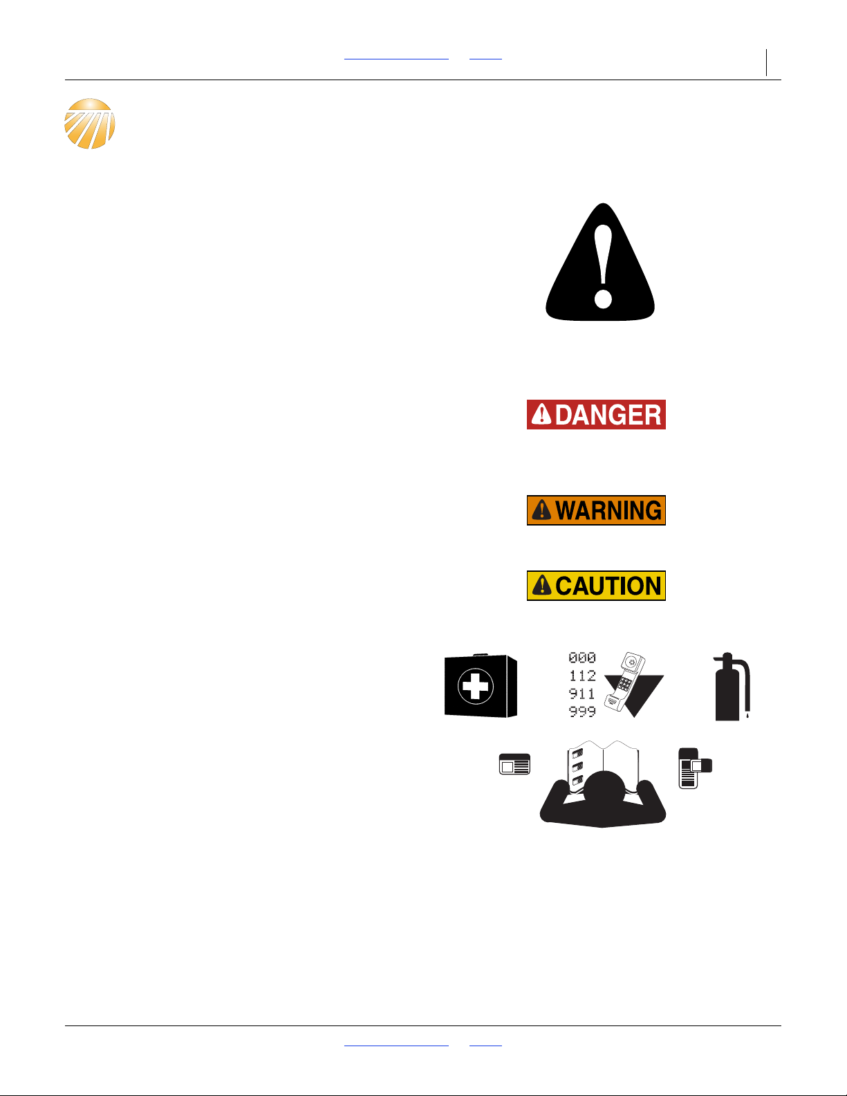
Look for Safety Symbol
The SAFETY ALERT SYMBOL indicates there is a
potential hazard to personal safety involved and extra
safety precaution must be taken. When you see this
symbol, be alert and carefully read the message that
follows it. In addition to design and configuration of
equipment, hazard control and accident prevention are
dependent upon the awareness, concern, prudence and
proper training of personnel involved in the operation,
transport, maintenance and storage of equipment.
Be Aware of Signal Words
Signal words designate a degree or level of hazard
seriousness.
DANGER indicates an imminently hazardous situation
which, if not avoided, will result in death or serious injury.
This signal word is limited to the most extreme situations,
typically for machine components that, for functional
purposes, cannot be guarded.
WARNING indicates a potentially hazardous situation
which, if not avoided, could result in death or serious
injury, and includes hazards that are exposed when
guards are removed. It may also be used to alert against
unsafe practices.
CAUTION indicates a potentially hazardous situation
which, if not avoided, may result in minor or moderate
injury. It may also be used to alert against unsafe
practices.
Prepare for Emergencies
Be prepared if a fire starts.
Keep a first aid kit and fire extinguisher handy.
Keep emergency numbers for doctor, ambulance, hospital
and fire department near phone.
Be Familiar with Safety Decals
Read and understand “Safety Decals” on page 6,
thoroughly.
Read all instructions noted on the decals.
Keep decals clean. Replace damaged, faded and illegible
decals.
2018-08-02 Table of Contents Index 155-015M-A
Page 6
2SF24 and 2SF30 Table of Contents Index Important Safety Information 2
Wear Protective Equipment
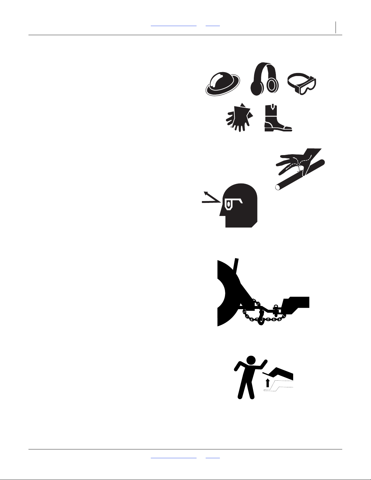
Wear protective clothing and equipment.
Wear clothing and equipment appropriate for the job.
Avoid loose-fitting clothing.
Because prolonged exposure to loud noise can cause
hearing impairment or hearing loss, wear suitable
hearing protection such as earmuffs or earplugs.
Because operating equipment safely requires your full
attention, avoid wearing entertainment headphones while
operating machinery.
Avoid High Pressure Fluids
Escaping fluid under pressure can penetrate the skin,
causing serious injury. This drill requires a
Power-Beyond port, which is always under pressure
when the tractor is running.
Avoid the hazard by relieving pressure at other remotes,
and shutting down tractor before connecting,
disconnecting or inspecting hydraulic lines.
Use a piece of paper or cardboard, NOT BODY PARTS, to
check for suspected leaks.
Wear protective gloves and safety glasses or goggles when
working with hydraulic systems.
If an accident occurs, seek immediate medical assistance
from a physician familiar with this type of injury.
Use A Safety Chain
Use a safety chain to help control drawn machinery
should it separate from tractor draw-bar.
Use a chain with a strength rating equal to or greater than
the gross weight of towed machinery.
Attach chain to tractor draw-bar support or specified
anchor location. Allow only enough slack in chain for
turns.
Replace chain if any links or end fittings are broken,
stretched or damaged.
Do not use safety chain for towing.
Negative Tongue Weight
This drill can have positive and negative tongue weight,
and it can change during planting. This poses a serious
hazard during unhitching and it can work the hitch pin
loose during transport. To avoid serious injury or death
due to a rising hitch or road accident.
Always use a leveling hitch pin.
Always use the hitch provided.
Always hitch before connecting hydraulics.
Always lower the openers or fold the drill and install the
jackstand before unhitching.
2018-08-02 Table of Contents Index 155-015M-A
Page 7
2SF24 and 2SF30 Table of Contents Index Important Safety Information 3
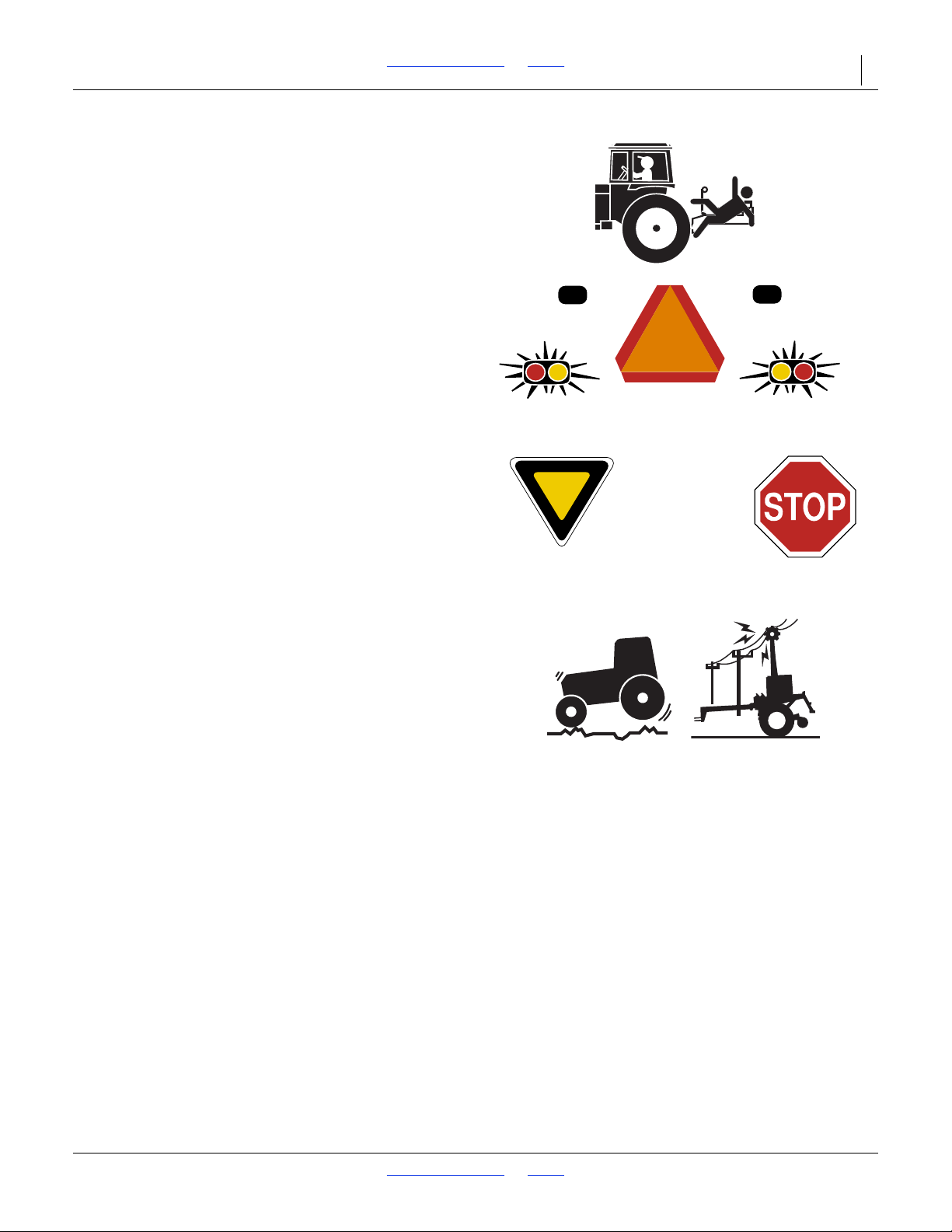
Keep Riders Off Machinery
Riders obstruct the operator’s view. Riders could be
struck by foreign objects or thrown from the machine.
Never allow children to operate equipment.
Keep all bystanders away from machine during operation.
Use Safety Lights and Devices
Slow-moving tractors and towed implements can create
a hazard when driven on public roads. They are difficult
to see, especially at night.
Use flashing warning lights and turn signals whenever
driving on public roads.
Use lights and devices provided with implement.
Transport Machinery Safely
Maximum transport speed for implement is 20 mph (32
kph), 13 mph (22 kph) in turns. Some rough terrains
require a slower speed. Sudden braking can cause a
towed load to swerve and upset.
Do not exceed 20 mph. Never travel at a speed which does
not allow adequate control of steering and stopping.
Reduce speed if towed load is not equipped with brakes.
Comply with state and local laws.
Do not tow an implement that, when fully loaded, weighs
more than 1.5 times the weight of towing vehicle.
Carry reflectors or flags to mark drill in case of
breakdown on the road.
Keep clear of overhead power lines and other
obstructions when transporting. Refer to transport
dimensions under “Specifications and Capacities” on
page 65.
Do not fold or unfold the drill while the tractor is moving.
2018-08-02 Table of Contents Index 155-015M-A
Page 8
2SF24 and 2SF30 Table of Contents Index Important Safety Information 4
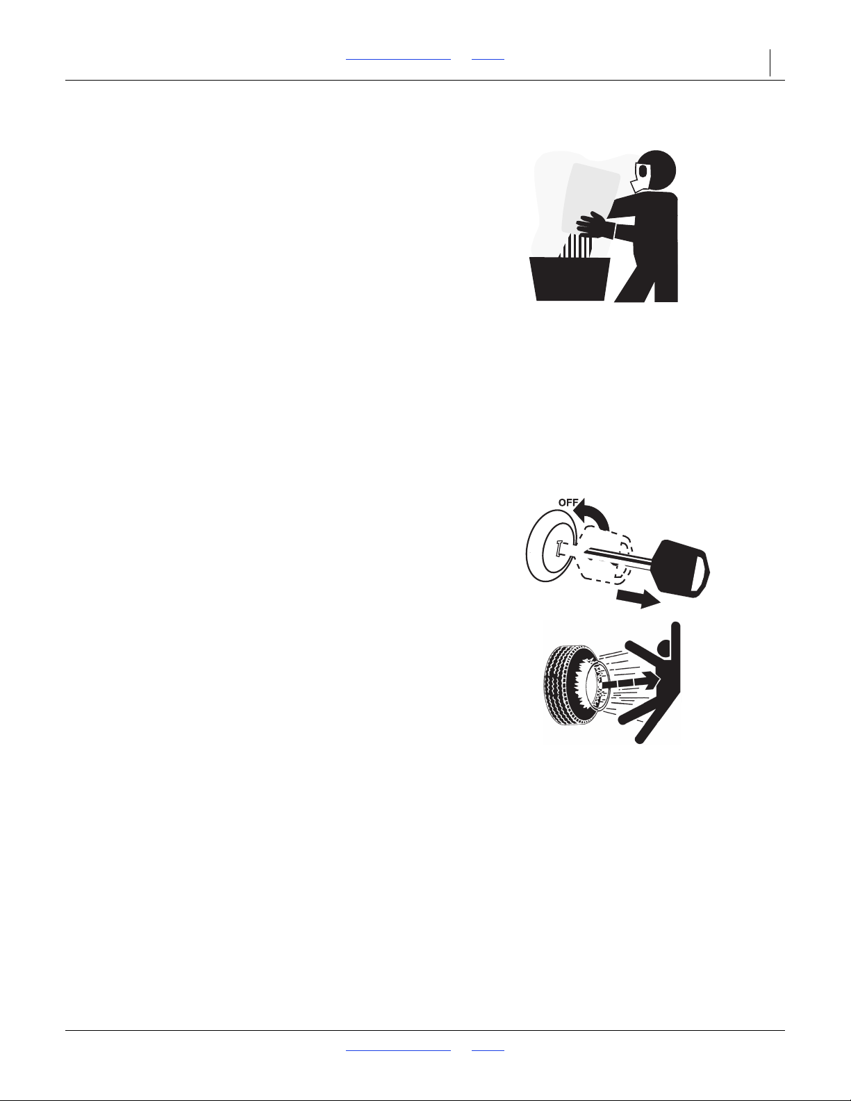
Handle Chemicals Properly
Agricultural chemicals can be dangerous. Improper use
can seriously injure persons, animals, plants, soil and
property.
Do not use liquid treatments with drill.
Read and follow chemical supplier instructions.
Wear protective clothing.
Handle all chemicals with care.
Agricultural chemicals can be dangerous. Improper use
can seriously injure persons, animals, plants, soil and
property.
Store or dispose of unused chemicals as specified by the
chemical manufacturer.
Dispose of empty chemical containers properly. By law
rinsing of the used chemical container must be repeated
three times. Puncture the container to prevent future use.
An alternative is to jet-rinse or pressure rinse the
container.
Never wash out a hopper within 100 feet (30 m) of any
freshwater source or in a car wash.
Shutdown and Storage
Lower drill, put tractor in park, turn off engine, and
remove the key.
Secure drill using blocks and supports provided.
Detach and store drill in an area where children normally
do not play.
Tire Safety
Tire changing can be dangerous. Employ trained
personnel using correct tools and equipment.
When inflating tires, use a clip-on chuck and extension
hose long enough for you to stand to one side–not in front
of or over tire assembly. Use a safety cage if available.
When removing and installing wheels, use wheel-handling
equipment adequate for weight involved.
2018-08-02 Table of Contents Index 155-015M-A
Page 9
2SF24 and 2SF30 Table of Contents Index Important Safety Information 5
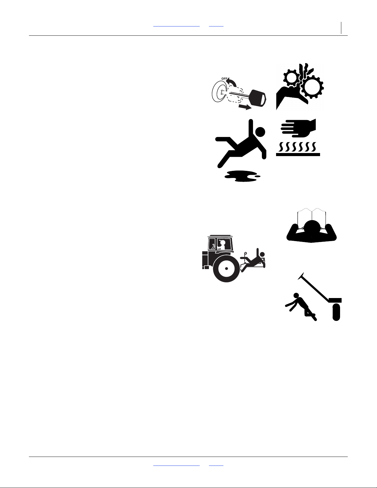
Practice Safe Maintenance
Understand procedure before doing work. Use proper
tools and equipment. Refer to this manual for additional
information.
Work in a clean, dry area.
Lower the drill, put tractor in park, turn off engine, and
remove key before performing maintenance.
Make sure all moving parts have stopped and all system
pressure is relieved.
Allow drill to cool completely.
Disconnect battery ground cable (-) before servicing or
adjusting electrical systems or before welding on drill.
Inspect all parts. Make sure parts are in good condition
and installed properly.
Remove buildup of grease, oil or debris.
Remove all tools and unused parts from drill before
operation.
Safety At All Times
Thoroughly read and understand the instructions in this
manual before operation. Read all instructions noted on
the safety decals.
Be familiar with all drill functions.
Operate machinery from the driver’s seat only.
Do not leave drill unattended with tractor engine running.
Do not stand between the tractor and drill during
hitching.
Keep hands, feet and clothing away from power-driven
parts.
Wear snug-fitting clothing to avoid entanglement with
moving parts.
Watch out for wires, trees, etc., when folding and raising
drill. Make sure all persons are clear of working area.
2018-08-02 Table of Contents Index 155-015M-A
Page 10
2SF24 and 2SF30 Table of Contents Index Important Safety Information 6
68418A
68418B
Safety Decals
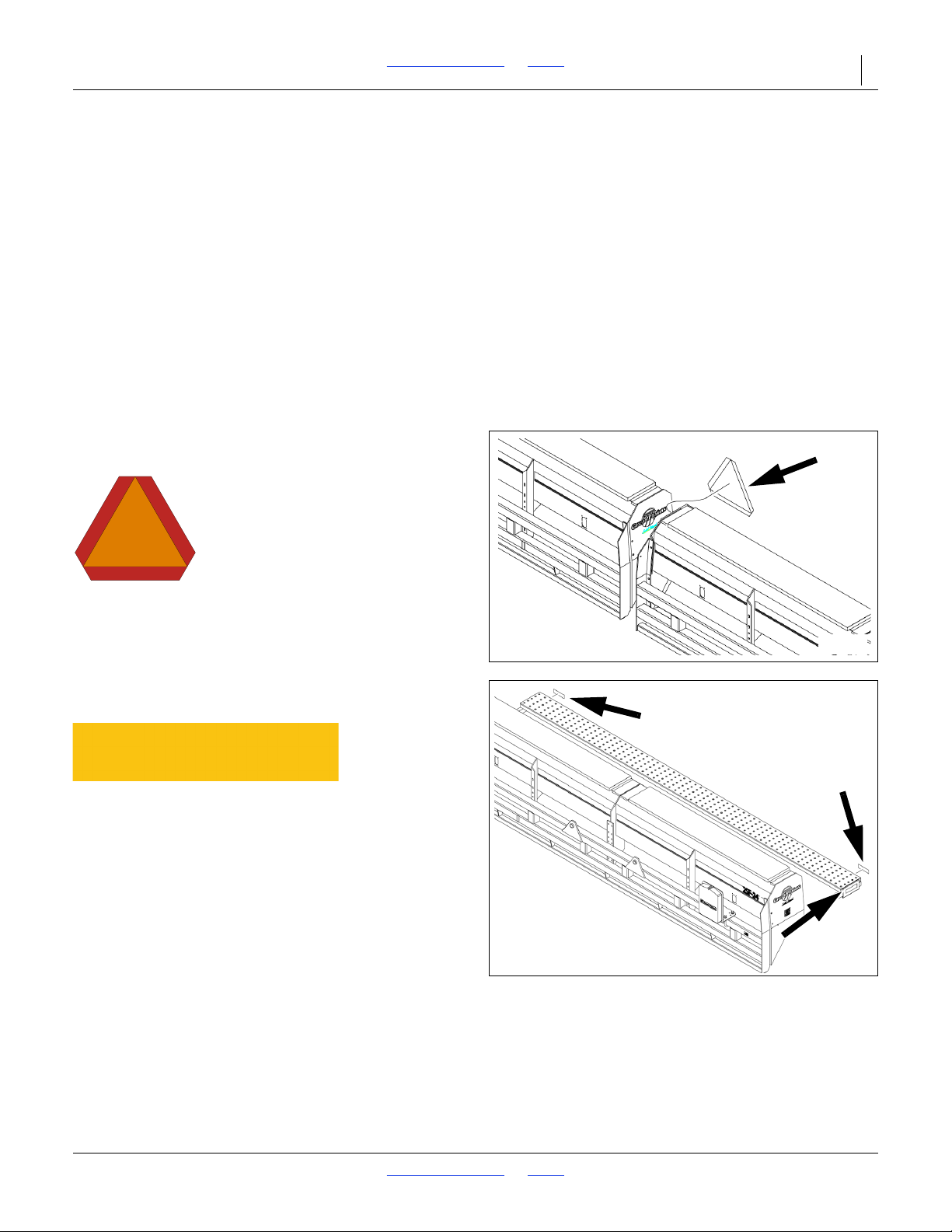
Safety Reflectors and Decals
Your implement comes equipped with all lights, safety
reflectors and decals in place. They were designed to
help you safely operate your implement.
Read and follow decal directions.
Keep lights in operating condition.
Keep all safety decals clean and legible.
Replace all damaged or missing decals. Order new decals
from your Great Plains dealer. Refer to this section for
proper decal placement.
When ordering new parts or components, also request
corresponding safety decals.
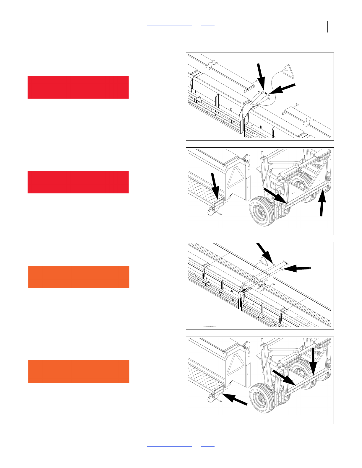
Slow Moving Vehicle Reflector
818-003C
To install new decals:
1. Clean the area on which the decal is to be placed.
2. Peel backing from decal. Press firmly on surface,
being careful not to cause air bubbles under decal.
On the right end of left-hand seed box (facing rear in
transport);
1 total
Amber Reflectors
838-265C
On the outside face of the right and left walkboard, on the
rear face at both ends of the right and left walkboard;
6 total
2018-08-02 Table of Contents Index 155-015M-A
Page 11
2SF24 and 2SF30 Table of Contents Index Important Safety Information 7
11366
68418C
19948
68418C
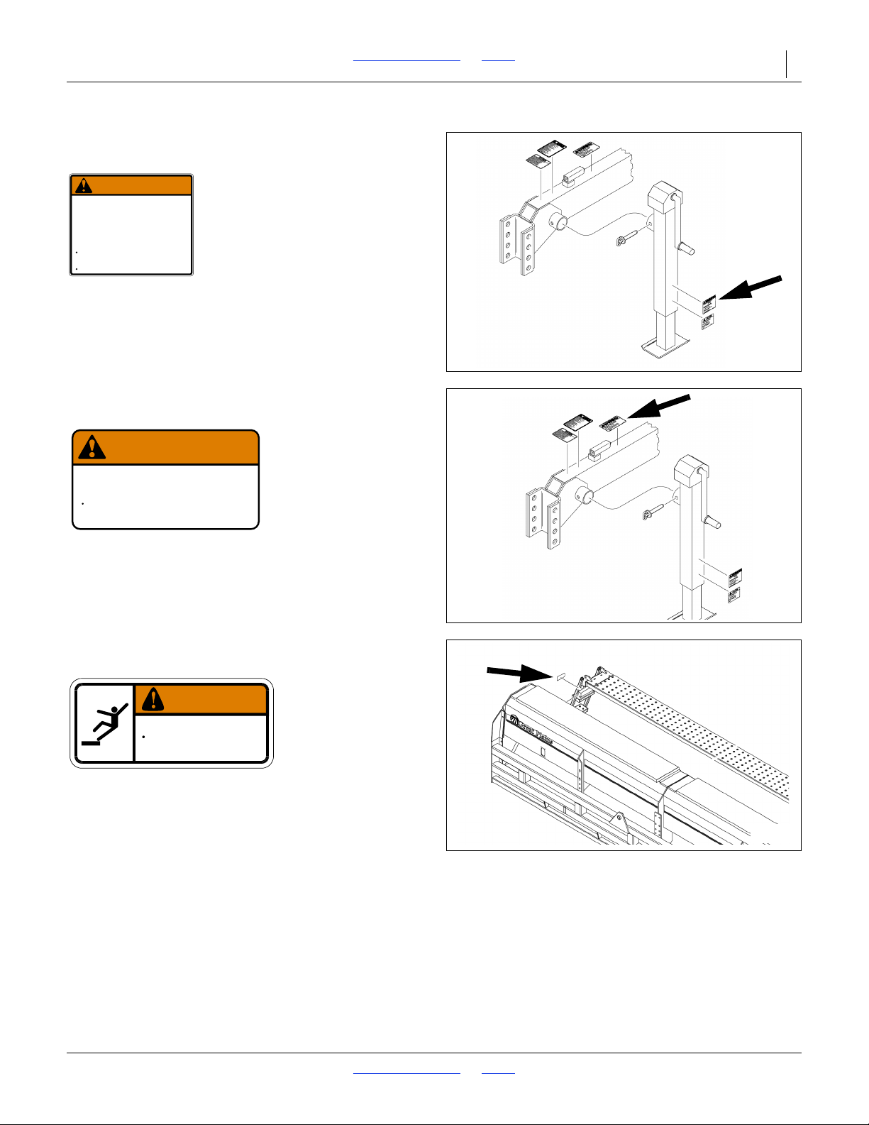
Red Reflectors
(2SF24 S/N 3508F-) (2SF30 S/N 3973G-)
838-266C
On the inside face of the seed hoppers (facing rear in
transport);
2 total
Red Reflectors
(2SF24 S/N 3509F+) (2SF30 S/N 3974G+)
838-266C
On the inside face of the walkboard on each seed box
(facing rear in transport), on the rear face of frame;
4 total
Daytime Reflectors
(2SF24 S/N 3508F-) (2SF30 S/N 3973G-)
838-267C
On the center inside face of right and left hopper section;
2 total
Daytime Reflectors
(2SF24 S/N 3509F+) (2SF30 S/N 3974G+)
838-267C
On the inside face of the walkboard on each seed box
(facing rear in transport), on the rear face of frame;
4 total
2018-08-02 Table of Contents Index 155-015M-A
Page 12
2SF24 and 2SF30 Table of Contents Index Important Safety Information 8
68418D
WARNING
NEGATIVE TONGUE WEIGHT
HAZARD
Negative tongue weight can cause immediate
elevation of tongue when unhitching implement
To prevent serious injury or death:
Always be certain implement is hitched securely
to tractor drawbar before raising.
Lower implement BEFORE unhitching.
818-019C Rev. D
68418D
818-188C Rev. C
Do Not exceed 20 mph maximum transport
speed. Loss of vehicle control and/or machine
can result.
To Prevent Serious Injury or Death:
EXCESSIVE SPEED HAZARD
WARNING
68418E
WARNING
To avoid serious injury or death:
Watch your step when climbing ladder or
walking on walkboard.
838-102C
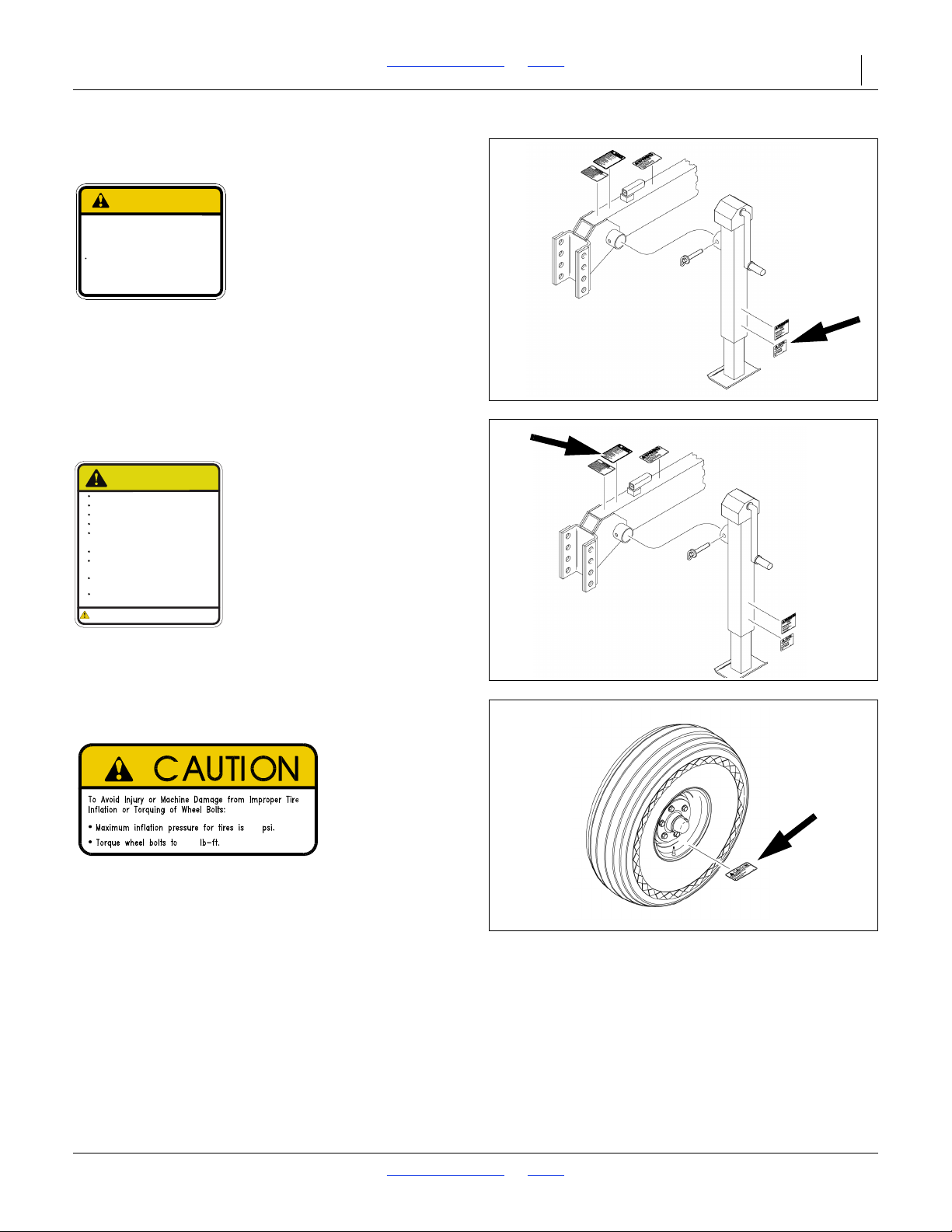
Warning: Negative Tongue Weight Hazard
818-019C
On the lower left face of the parking stand;
1 total
Warning: Excessive Speed Hazard
818-188C
On top face of transport lock weldment on tongue;
1 total
Warning: Falling Hazard
838-102C
On right outside face of walkboard by ladder on
right-hand seed box;
1 total
2018-08-02 Table of Contents Index 155-015M-A
Page 13
2SF24 and 2SF30 Table of Contents Index Important Safety Information 9
68418D
818-020C Rev. B
Do Not lower drill in folded
position - tire damage may
result.
To Avoid Machine Damage:
TIRE DAMAGE HAZARD
CAUTION
68418D
WARNING:
Cancer and Reproductive Harm - www.P65Warnings.ca.gov
Read Owner’s Manual before using machine.
Stand clear when folding and unfolding markers.
Stand clear when raising and lowering machine.
Keep all safety shields and devices in place.
Keep hands, feet, and clothing away from
Never ride on machine.
Always lower or properly support machine
Escaping hydraulic fluid can cause serious
Review safety instructions with all operators
moving chains and sprockets.
BEFORE servicing.
818-587C Rev. B
injury.
annually.
CAUTION
68418F
44
85
858-669C
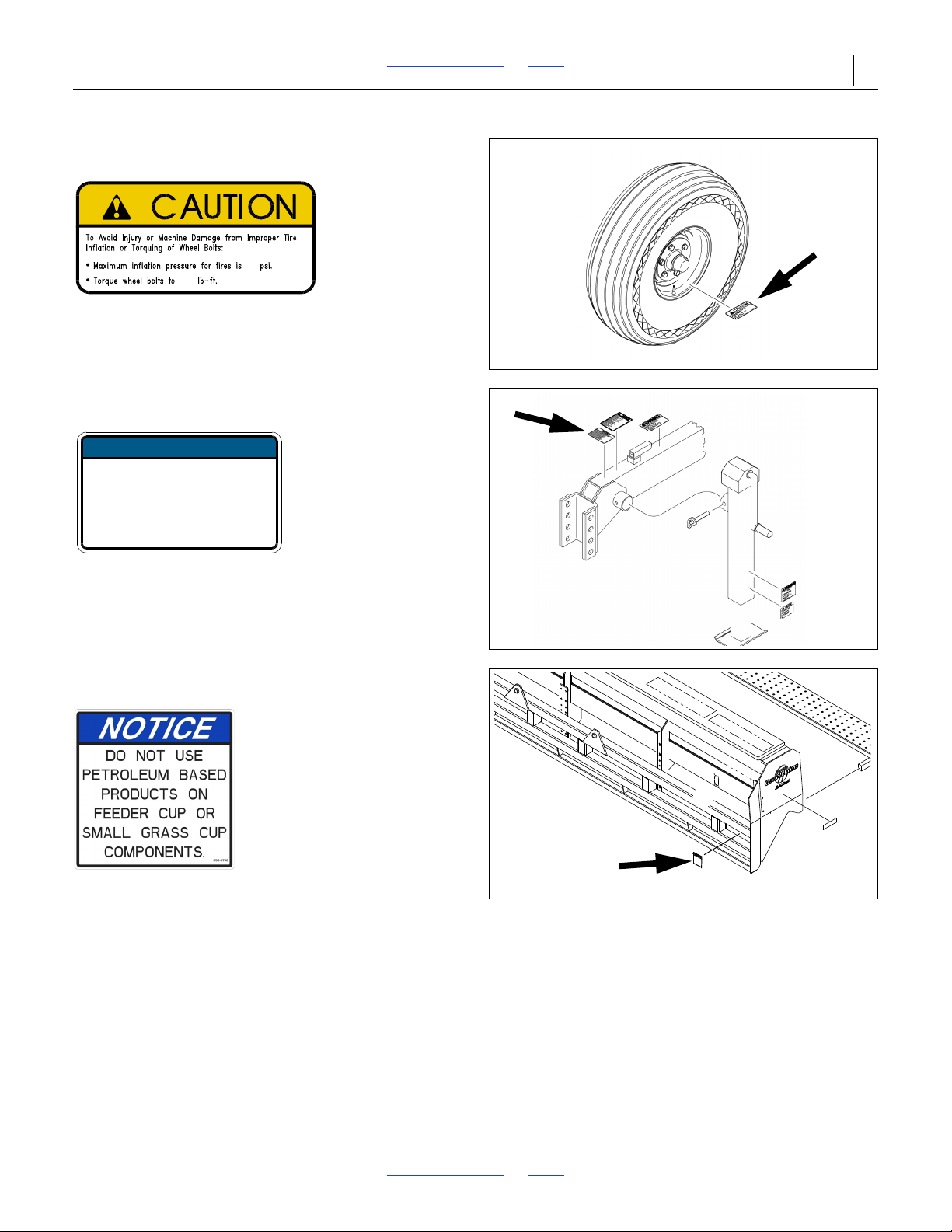
Caution: Tire Damage Hazard
818-020C
On the lower left face of the parking stand:
1 total
Caution: Read Operator’s Manual
818-587C
On top face of tongue near hitch;
1 total
Caution: 44 PSI Tire Pressure
858-669C
On rim of each gauge wheel;
2 total (single gauge wheels)
4 total (dual gauge wheels)
2018-08-02 Table of Contents Index 155-015M-A
Page 14
2SF24 and 2SF30 Table of Contents Index Important Safety Information 10
68418F
4
85
858-C
68418D
818-043C Rev. A
This machine is equipped with rephasing master slave lift cylinders which
may after a period of time get out of time or phase. An indication of
this is when one section is running too low or too high because its lift
cylinder is either overextended or overetracted compared to the other lift
cylinders. To rephase the cylinders, raise the implement completely up and
hold the tractor hydraulic lever on for a few seconds giving the cylinders
time to rephase. This should be done each time the machine is ra
ised out
of the ground. Momentarily reversing the hydraulic lever immediately after
rephasing to allow the cylinders to retract about 1/2” will help to maintain
a level implement.
LIFT CYLINDERS OPERATING INSTRUCTIONS
NOTICE
2SF-24
Caution: 64 PSI Tire Pressure
858-669C
On rim of each transport wheel;
4 total
Notice: Lift Cylinder Operating Instructions
818-043C
On top face of tongue near hitch;
1 total
Notice: General Instructions
858-679C
Front frame, both ends;
2 total
2018-08-02 Table of Contents Index 155-015M-A
Page 15
2SF24 and 2SF30 Table of Contents Index 11
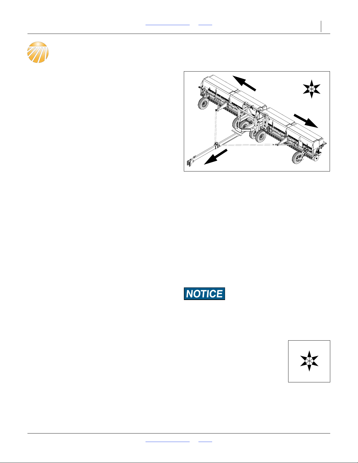
Figure 1
Two Section Folding Drill
36149
L
R
U
D
F
B
L
R
U
D
F
B
L
R
Introduction
Great Plains welcomes you to its growing family of new
product owners. The Two Section Folding Drills have been
designed with care and built by skilled workers using
quality materials. Proper setup, maintenance, and safe
operating practices will help you get years of satisfactory
use from the machine.
Models Covered
2SF24-4806 48-Row,6 inch (15cm)
2SF24-4007 40-Row,7 inch (17.8cm)
2SF24-3875 38-Row,7.5 inch (19cm)
2SF24-3608 36-Row,8 inch (20cm)
2SF24-2810 28-Row,10 inch (25.4cm)
2SF30-6006 60-Row,6 inch (15cm)
2SF30-5207 52-Row,7 inch (17.8cm)
2SF30-4875 48-Row,7.5 inch (19cm)
2SF30-4408 44-Row,8 inch (20cm)
2SF30-3610 36-Row,10 inch (25.4cm)
Description of Unit
The 2SF24 and 2SF30 Drill is a towed precision planting
implement for use in conventional till conditions. The
2SF24 and 2SF30 features fluted feed cups and a
ground-driven metering system to provide accurate
simple seeding with offset double-disk openers that
provide superior penetration.
Intended Usage
Use the 2SF24 and 2SF30 drill to seed
production-agriculture crops only. Do not modify the drill
for use with attachments other than Great Plains options
and accessories specified for use with the 2SF24 and
2SF30.
Document Family
155-015M-A Owner’s Manual (this document)
155-015P Parts manual
Using This Manual
This manual will familiarize you with safety, assembly,
operation, adjustments, troubleshooting, and
maintenance. Read this manual and follow the
recommendations to help ensure safe and efficient
operation.
The information in this manual is current at printing.
Some parts may change to assure top performance.
Definitions
The following terms are used throughout this manual.
A crucial point of information related to the preceding topic.
Read and follow the directions to remain safe, avoid serious
damage to equipment and ensure desired field results.
NOTE:
Useful information related to the preceding topic.
Right-hand and left-hand as used in
this manual are determined by facing
the direction the machine will travel
while in use unless otherwise stated.
An orientation rose shows the
directions of: Up, Back, Left, Down,
Front, Right.
2018-08-02 Table of Contents Index 155-015M-A
Page 16
2SF24 and 2SF30 Table of Contents Index Introduction 12
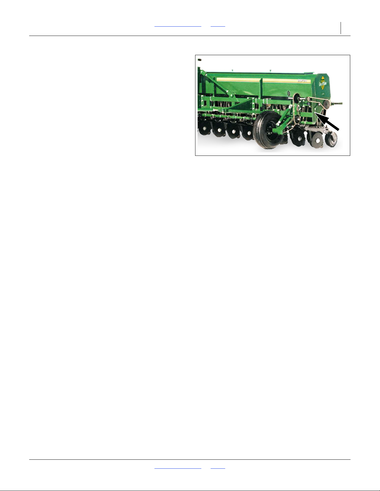
Figure 2
Serial Number Plate
36129
Owner Assistance
If you need customer service or repair parts, contact a
Great Plains dealer. They have trained personnel, repair
parts and equipment specially designed for Great Plains
products.
Refer to Figure 2
Your machine’s parts were specially designed and
should only be replaced with Great Plains parts. Always
use the serial and model number when ordering parts
from your Great Plains dealer. The serial-number plate is
located on the left outside end of the front upper tool bar.
Record your 2SF24 or 2SF30 drill model and serial
number here for quick reference:
Model Number:__________________________
Serial Number: __________________________
Your Great Plains dealer wants you to be satisfied with
your new machine. If you do not understand any part of
this manual or are not satisfied with the service received,
please take the following actions.
1. Discuss the matter with your dealership service
manager. Make sure they are aware of any problems
so they can assist you.
2. If you are still unsatisfied, seek out the owner or
general manager of the dealership.
Further Assistance
Great Plains Manufacturing, Inc. wants you to be
satisfied with your new product. If for any reason you do
not understand any part of this manual or are otherwise
dissatisfied, please contact:
Great Plains Service Department
1525 E. North St.
P.O. Box 5060
Salina, KS 67402-5060
Or go to www.greatplainsag.com and follow the contact
information at the bottom of your screen for our service
department.
2018-08-02 Table of Contents Index 155-015M-A
Page 17

2SF24 and 2SF30 Table of Contents Index 13
Preparation and Setup
This section helps you prepare your tractor and 2SF24 or
2SF30 Drill for use, and covers tasks that need to be
done seasonally, or when the tractor/drill configuration
changes.
Before using the drill in the field, you must hitch it to a
suitable tractor, inspect systems and level the drill.
Before using the drill for the first time, and periodically
thereafter, certain adjustments and calibrations are
required.
Initial Setup
See“Appendix B - Assembly and Setup” on page 69
for first-time/infrequent setup tasks.
Post-Delivery/Seasonal Setup
On initial delivery, use with a new tractor, and seasonally,
check and as necessary, complete these items before
continuing to the routine setup items:
• Bleed hydraulic system (page 18).
• De-grease exposed cylinder rods if so protected at
last storage.
Pre-Planting Setup
Complete this checklist before routine setup:
Read and understand “Important Safety
Information” on page 1.
Check that all working parts are moving freely, bolts
are tight, and cotter pins are spread.
Check that all grease fittings are in place and
lubricated. See “Lubrication and Scheduled
Maintenance” on page 60.
Check that all safety decals and reflectors are
correctly located and legible. Replace if damaged.
See “Safety Decals” on page 6.
Inflate tires to pressure recommended and tighten
wheel bolts as specified. See “Tire Inflation Chart”
on page 68.
2018-08-02 Table of Contents Index 155-015M-A
Page 18
2SF24 and 2SF30 Table of Contents Index Preparation and Setup 14
Hitching Tractor to Drill
Great Plains 2-Section Folding Drills are engineered to
be used with tractors having a standard drawbar. To
operate your Great Plains Folding Drill in most field
conditions, a tractor of 125 minimum horsepower for
24 foot drills and 150 minimum horsepower for 30 foot
drills should be used.
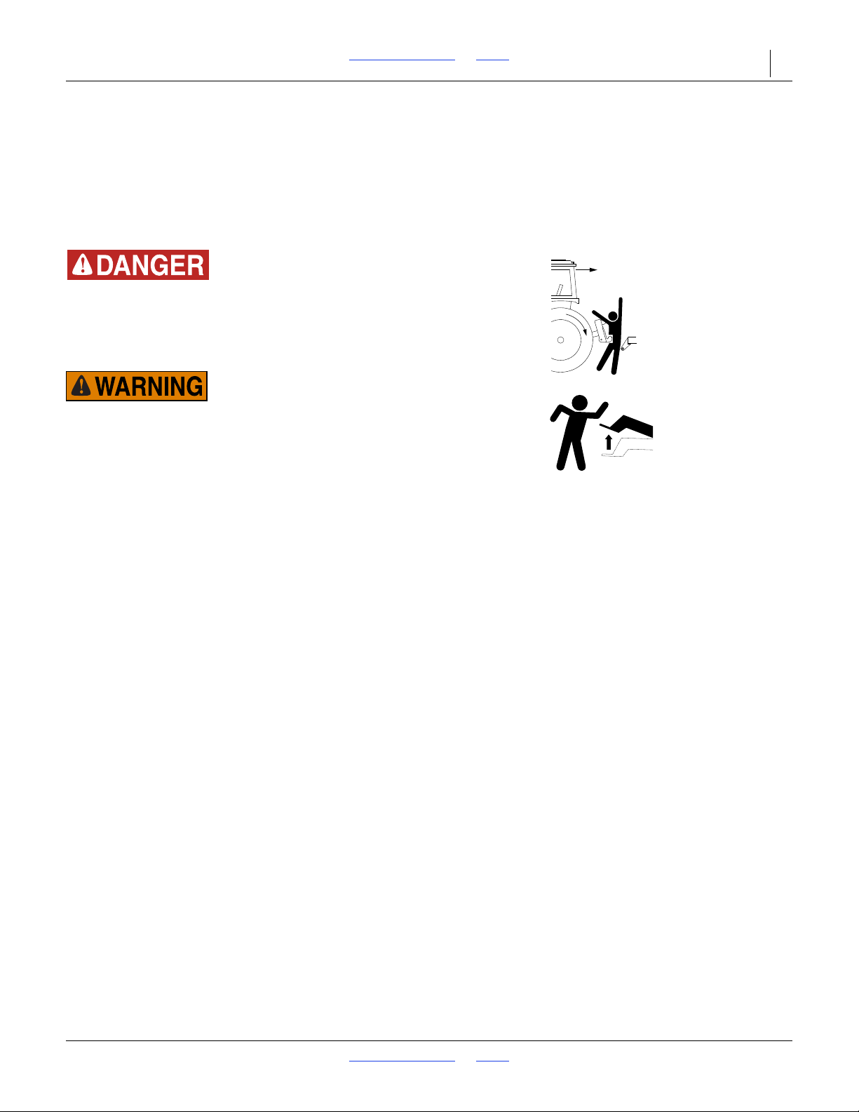
Crushing Hazard:
Do not stand or place any body part between drill and moving
tractor. You may be severely injured or killed by being crushed
between the tractor and drill. Stop tractor engine and set
parking brake before attaching cables and hoses.
Negative Tongue Weight Hazard:
This drill can have both positive and Negative Tongue Weight
and it can change during planting. This poses a serious hazard
during unhitching and it can work the hitch pin loose during
transport. Never unhook from tractor with boxes unfolded and
raised off the ground.
2018-08-02 Table of Contents Index 155-015M-A
Page 19
2SF24 and 2SF30 Table of Contents Index Preparation and Setup 15
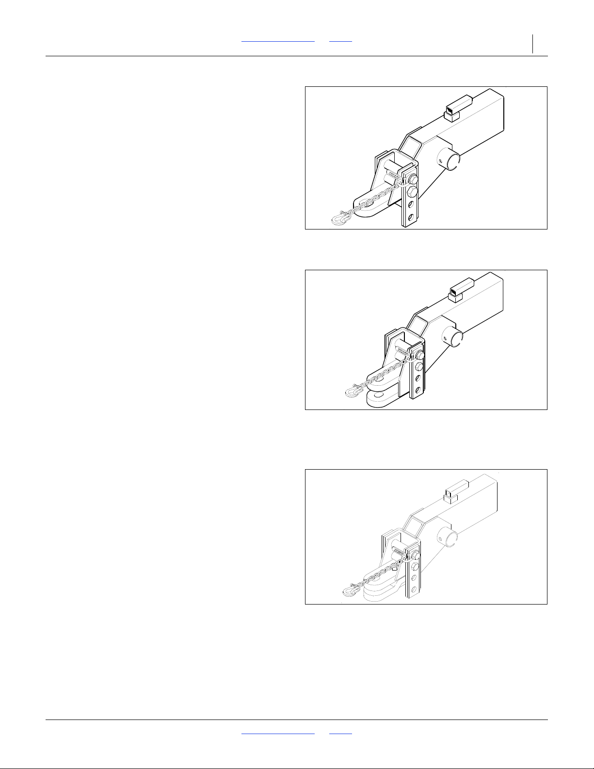
Figure 3
Single Strap Hitch
11638
Figure 4
Clevis Hitch
11637
Figure 5
Combination Hitch
17274
Tractor Draw Bar Hook-Up
Refer to Figure 3, Figure 4 and Figure 5
1. The hitch can be used as either a single strap, clevis,
or combination hitch.
2. When using the combination hitch, remove lower
strap when hooking up to a clevis-type tractor
drawbar. Spacers between the drawbar and hitch
may be added to eliminate some of the movement of
the tongue caused from positive to negative tongue
weight.
Two hitch sizes are available:
• the small hole hitch with or without the hammer strap
1
(1
/4 inch maximum pin diameter) and
• the large hole hitch without a hammer strap (up to
1
1
/2inch diameter pin). The small-hole hitch is sold
as standard equipment.
The mounting holes in the hitch have been offset so the
hitch can be turned over and bolted on in three different
positions giving you six different hitch heights.
On the clevis-type hitch, always mount the thinner strap
on the bottom.
NOTE:
Set hitch so tongue of drill is parallel to ground when
drill is in planting position. Use tongue jack to level
tongue, then find closest setting of hitch to match your
tractor drawbar height.
3. Attach safety chain on tongue hitch to tractor and
lock hook securely on chain. Adjust chain length to
remove all slack except what is necessary to permit
turning of the drill and tractor.
4. The tongue jack makes it possible to raise or lower
the hitch for tractor unhooking and reconnecting.
Always return jack to its horizontal position on top of
the tongue at the pull bar slide stop.
2018-08-02 Table of Contents Index 155-015M-A
Page 20
2SF24 and 2SF30 Table of Contents Index Preparation and Setup 16
Figure 6
Color Coded Hose Handles
31733
Hydraulic Hose Hookup
High Pressure Fluid Hazard:
Shut down tractor before making hydraulic connections.
Only trained personnel should work with system hydraulics.
Escaping fluid under pressure can have sufficient pressure to
penetrate the skin causing serious injury. If an accident
occurs, seek immediate medical assistance from a physician
familiar with this type of injury. Use paper or cardboard, NOT
BODY PARTS, to check for leaks. Wear protective gloves and
safety glasses or goggles when working with hydraulic
systems.
For ease of operation, your tractor should be equipped
with six remote hydraulic outlets (three pairs). This will
allow you to connect one pair to the drill lift circuit, one
pair to your drill fold circuit and one pair remaining for
connection of optional markers. If your tractor has only
four remote outlets (two pairs) and a marker circuit is
required, a marker sequences valve with double selector
is available through your Great Plains Dealer.
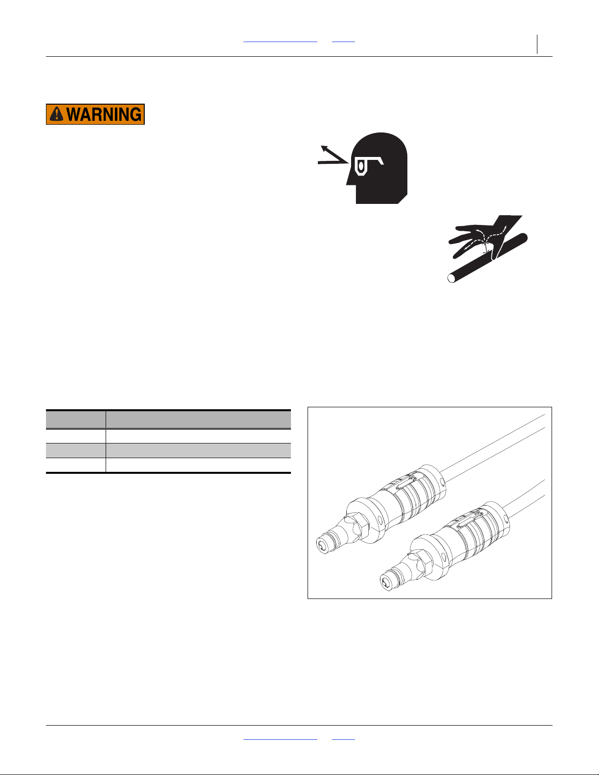
Refer to Figure 6
Great Plains hydraulic hoses have color coded handle
grips to help you hookup hoses to your tractor outlets.
Hoses that go to the same remote valve are marked with
the same color.
Color Coded Hose Handles
Color Hydraulic Function
Blue Lift
Gray Fold
Green Marker (Optional)
To distinguish hoses on the same hydraulic circuit, refer
to the symbol molded into the handle grip. Hoses with an
extended-cylinder symbol feed cylinder base ends.
Hoses with a retracted-cylinder symbol feeds cylinder
rod ends.
For hydraulic fan and drive motors, connect the hose
under the retracted cylinder symbol to the pressure side
of the motor. Connect the hose under the extended
cylinder symbol to the return side of the motor.
2018-08-02 Table of Contents Index 155-015M-A
Page 21
2SF24 and 2SF30 Table of Contents Index Preparation and Setup 17
Figure 7
Older Style Hoses w/Label
27270
Older Style Hoses with Color Ties
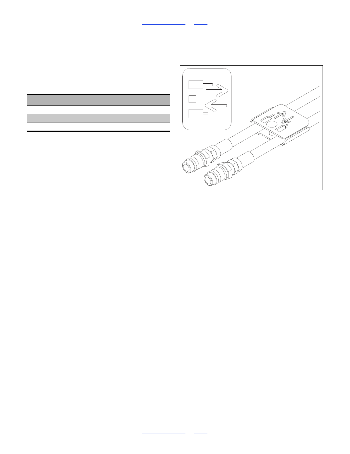
Refer to Figure 7
Great Plains hydraulic hoses are color coded to help you
hookup hoses to your tractor outlets. Hoses that go to
the same remote valve are marked with the same color
tie.
Color Hydraulic Function
Blue Lift
White Fold
Orange Marker (Optional)
To distinguish hoses on the same hydraulic circuit, refer
to hose label. The hose under an extended-cylinder
symbol feeds a cylinder base end. The hose under a
retracted-cylinder symbol feeds a cylinder rod end.
For hydraulic fan and drive motors, connect the hose
under the retracted cylinder symbol to the pressure side
of the motor. Connect the hose under the extended
cylinder symbol to the return side of the motor.
2018-08-02 Table of Contents Index 155-015M-A
Page 22

2SF24 and 2SF30 Table of Contents Index Preparation and Setup 18
Bleeding Hydraulic Systems
4. Hydraulically retract the cylinders, then repeat the
extending procedure several more times until both
Negative Tongue Weight Hazard:
This drill has a Negative Tongue Weight when unfolded and
raised. Be certain that the drill is hitched securely to your
tractor draw bar and be certain the hitch safety chain is
securely attached to the drill hitch and tractor before raising
or unfolding the drill!
Equipment Damage Risk:
When using sealant on pipe threads the friction between the
threads is reduced; therefore, be certain not to over tighten,
causing damage to a valve, cylinder port or fitting.
NOTE:
The SAE O-RING and JIC 37° FLARE type hose
connections do not require sealant for reconnecting.
They do not require high torque for a good seal.
Bleeding the Lifting Hydraulic System
This Drill is equipped with rephasing type hydraulic lift
cylinders that require a special procedure for bleeding air
from the hydraulic system. If your dealer has not already
prepared the cylinders for transport use, read the
following information carefully. The rephasing cylinders
will not function properly if this bleeding procedure is not
followed. Do not crack hose fittings in order to bleed air
from this system.
NOTE:
Check the hydraulic fluid level in the tractor reservoir
and fill to the proper level before starting this
procedure. If the bleeding is performed with a low
reservoir supply, there is a chance of drawing air into
the system. System capacity is approximately 3.3
gallons and requires one pair of remote outlets.
1. If required, raise your drill 1 inch in order to extend
your lift cylinders a little. Loosen the jam nuts on top
of the transport vertical tubes and screw the
adjustment screw in until it bottoms. Lower the drill
until the cylinders become loose.
2. Unpin the cylinders from the mainframe and turn the
cylinders upside down to a position where the rod
end is higher than the base end. Support the
cylinders in a safe location. One transport tire may
have to be removed in order to unpin the master
cylinder.
3. Start the tractor and run the engine at idle. With the
rod end of the cylinders higher than the base end,
hydraulically extend the cylinders and hold the
tractor control lever in position for sixty seconds after
the cylinders have extended to their maximum
stroke.
cylinders are free of air and operate together.
5. Repin the cylinders to the main frame and axle with
the rod end down. If air is tapped in either cylinder,
the affected cylinder will have a spongy, erratic
movement and the machine will not raise evenly.
Refill the tractor hydraulic fluid reservoir to its proper
level.
NOTE:
After drill is raised, a slight settling will occur due to
the action of the rephasing cylinder.
NOTE:
In order to prevent trapped air pockets, the port on
the rod end must be higher than any other port of the
cylinder during the bleeding operation.
NOTE:
The folding and transport/wing lift cylinders are not
rephasing type cylinders and do not require this
bleeding procedure.
2018-08-02 Table of Contents Index 155-015M-A
Page 23
2SF24 and 2SF30 Table of Contents Index Preparation and Setup 19
Figure 8
Wing Fold Hydraulics
10285
Bleeding Folding Hydraulics
The following section describes a bleeding procedure
that requires you to crack (loosen) a hydraulic fitting. Be
aware that these lines may be under pressure even with
the tractor shut off. Never allow anyone under the drill
when fittings are opened. Escaping fluid may allow the
drill to suddenly drop. Be aware of the following medical
alert.
High Pressure Fluid Hazard:
Escaping fluid under pressure can have sufficient force to
penetrate the skin. Check all hydraulic lines and hoses before
applying pressure. Fluid escaping from a very small hole can
be almost invisible. Use paper or cardboard, not body parts, to
check for suspected leaks. If injured, seek medical assistance
from a doctor familiar with this kind of injury.
The drill transport lift systems should be completely
operational BEFORE attempting to work with the folding
hydraulic circuit.
NOTE:
The cylinders are double acting but are not the
rephasing type.
1. The first step in charging the fold hydraulic circuit is
to make sure the tractor hydraulic fluid reservoir is
filled to the proper level. System capacity is
approximately 2 gallons and requires one pair of
remote outlets. If optional selector is used, rotate to
the wing lift position.
2. With the drill fully raised and in the folded position,
disconnect the rod end pin on each fold cylinder and
block the cylinders in a location where they are free
to extend and retract without contacting anything.
3. Cycle the fold cylinders in and out several times to
work the air out of the system.
NOTE:
If the wing fold cylinders do not operate properly,
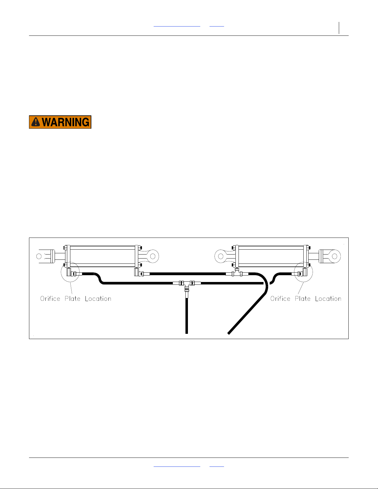
clean out the small hole in the elbow fitting on fold
cylinders. These orifice are located in the cylinder
elbow as circled in Figure 8.
4. Retract the hydraulic cylinder and repin the rod ends.
5. Recheck the tractor reservoir level and add clean
fluid as necessary.
6. It is advisable to fold and unfold the drill several
times. The majority of the air should now be expelled
from this system. The remaining air will gradually be
pushed to the tractor during day to day operations.
2018-08-02 Table of Contents Index 155-015M-A
Page 24
2SF24 and 2SF30 Table of Contents Index Preparation and Setup 20
Figure 9
Opener Spring Rods
10548
Leveling Drill
This section describes procedures for leveling the drill on
its initial setup. This should be a one-time adjustment
and will not be needed during day-to-day operation.
If while using the drill, it appears to be lifting or planting
unevenly, check the following before re-leveling the drill.
• First, make sure the tongue is running level to the
ground while running in the field. Be sure to check
this if the drill has been switched to a different tractor.
• Second, check the lift cylinders. Be sure they are
properly bled, are operating correctly, and do not
have internal oil leaks before using this section to
re-level the drill.
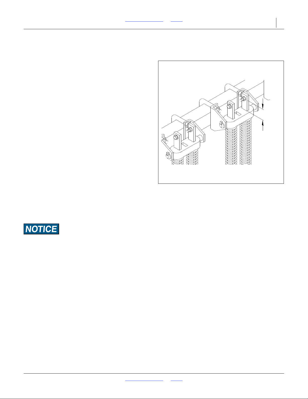
The opener spring rods located along the back of the drill
boxes are indicators of the level of the drill because they
show the amount of down-pressure exerted on the disk
openers and press wheels. A level drill will have equal
opener down-pressure from end to end.
Check the spring rod cross bolts at the top of the spring
rods to see that they are all extended about 2 inches
above their spring rod castings. This is a general
dimension and may vary with the spring down-pressure
you require for different soil conditions and planting
depths, see “Planting Depth Adjustments” on page 36.
If you require more downward float of your openers you
may want to increase this dimension. Keep in mind when
this dimension is increased your upward motion is
decreased, limiting the vertical travel of the openers for
running over rocks and other foreign objects.
2 in.
5.08 cm
Opener Damage Risk:
If your openers’ vertical travel is decreased, considerable
damage will occur to your openers.
If all the spring rods along the drill extend the same
distance above their castings, the drill is level and you
should tighten down the threaded studs as described in
“Transport Wheel Adjustments for Leveling Drill” on
page 21. If the spring-rod extensions vary in length, the
drill can be leveled with transport wheel and gauge
wheel adjustments. These are described on page 21.
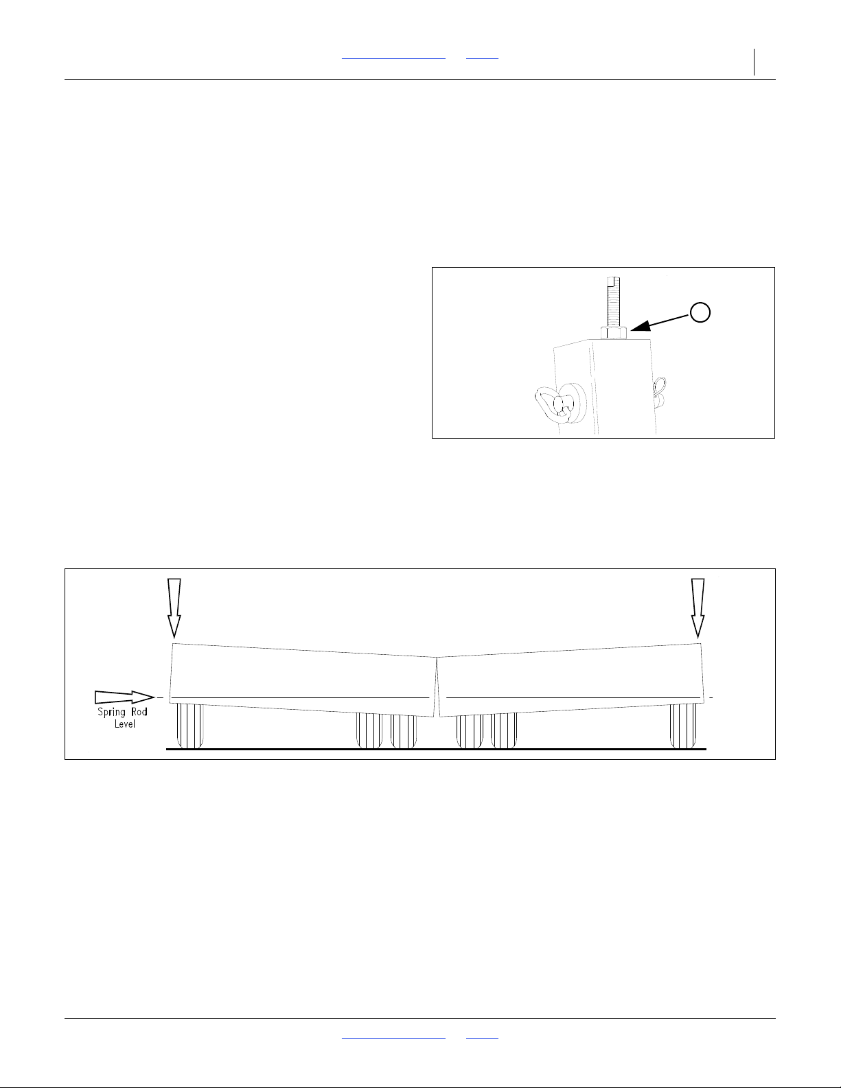
To summarize: After leveling your drill, it should have the
same dimension from the ground to the box frame at
both ends of each box. These adjustments may have to
be fine tuned after observing the drill in the field in actual
planting conditions.
2018-08-02 Table of Contents Index 155-015M-A
Page 25
2SF24 and 2SF30 Table of Contents Index Preparation and Setup 21
Figure 10
Threaded Stud
10672
1
Figure 11
Wing Fold Hydraulics
11504
Transport Wheel Adjustments for Leveling Drill
When leveling your drill, opener spring rods near the
center of the drill that extend higher above their spring
rod castings than desired can be adjusted by raising the
transport frame. This is done by raising the drill with the
hydraulic lift cylinders.
Spring rods near the center that do not extend high
enough are adjusted by lowering the transport frame by
retracting the cylinders.
Refer to Figure 11
Once the spring rods are at the desired setting, screw
the threaded studs on top of the vertical tubes down as
far as possible and secure them with the jam nuts (1).
This adjustment will stop the lift cylinder travel at the
same point each time the boxes are lowered for drilling
and assures accurate seed depth control.
NOTE:
If it is noticed that one drill box spring rod extension is
different from the other drill box at the center of your
drill, this is a sign that your lift hydraulic master and
slave cylinders are out of sequence with one another.
In order to get them back in sequence, simply raise
your drill all the way up and hold your tractor
hydraulic control valve lever on for a few seconds.
Lower your drill and both cylinders will be in
sequence with one another and the two drill boxes
should be at the same level again.
2018-08-02 Table of Contents Index 155-015M-A
Page 26
2SF24 and 2SF30 Table of Contents Index Preparation and Setup 22
Figure 12
Gauge Wheel Turnbuckle
10546
Figure 13
Opener Spring Rods
11284
Gauge Wheel Adjustments for Leveling Drill
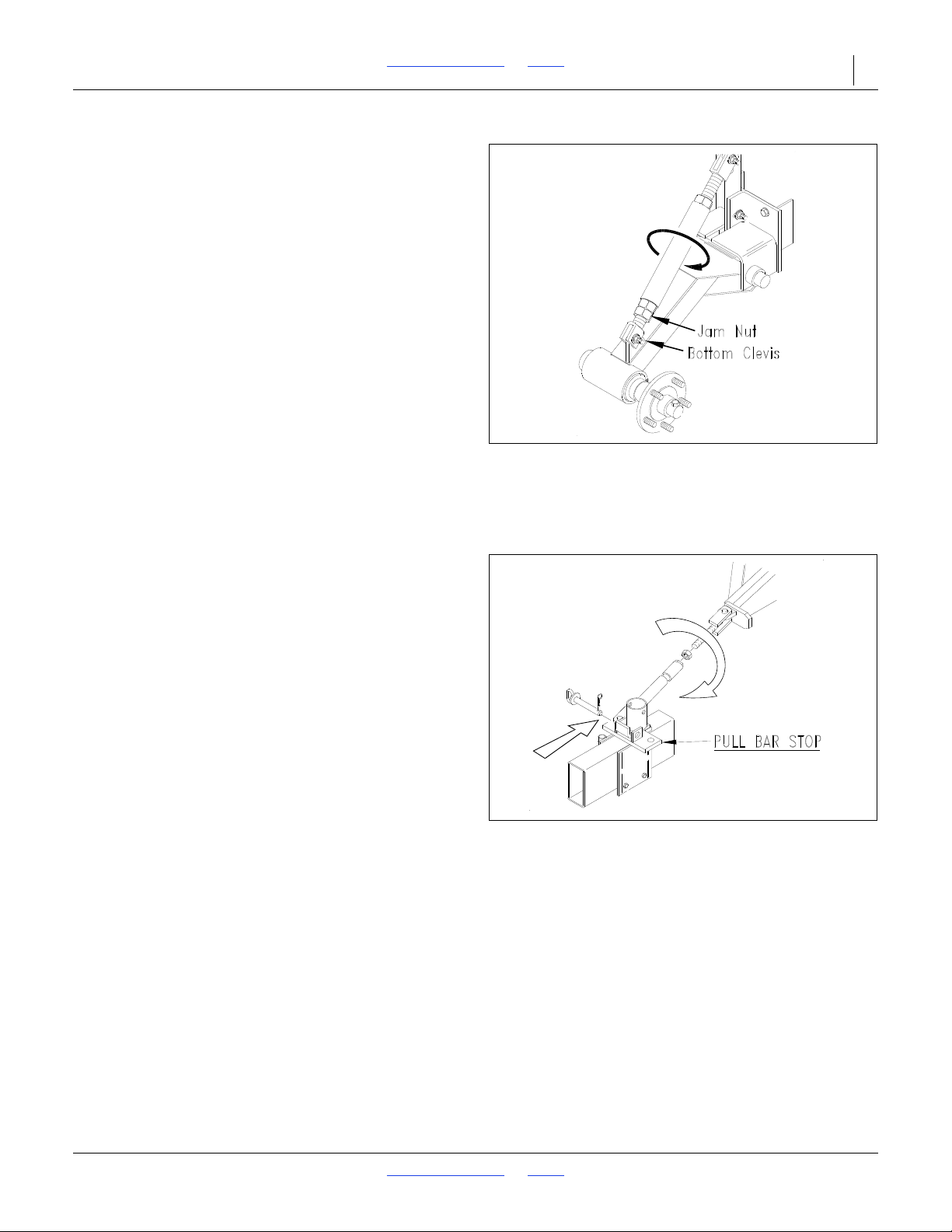
Refer to Figure 11 and Figure 12
The openers near the outside of the drill are adjusted by
raising or lowering the gauge wheels.
Raise the drill out of the ground and loosen the jam nut
located near the bottom clevis of the gauge wheel
turnbuckle. This turnbuckle is threaded to allow easy
gauge wheel adjustment.
• Lengthening the turnbuckle the gauge wheel is
lowered, causing less spring rod extension through
the spring rod casting.
• Shortening the turnbuckle the gauge wheel is raised,
causing less spring rod to protrude through the
spring rod casting.
After adjusting, be sure the turnbuckle on both gauge
wheel arms have the same pin center dimension.
Shortening the gauge wheel turnbuckle will level the
ends of the drill with the center.
Box Alignment Adjustments
Pull Bar Adjustments
Refer to Figure 13
With the drill lowered to the ground and completely
unfolded the tongue slide on the tongue should be back
against the stop on the tongue. Adjust the pull bars
length so drill boxes are in line with one another and
parallel to the back edge of the main frame.
2018-08-02 Table of Contents Index 155-015M-A
Page 27
2SF24 and 2SF30 Table of Contents Index Preparation and Setup 23
Figure 14
Top Slide Cylinder
10671
Figure 15
Threaded Stud
10672
Drill Adjustments
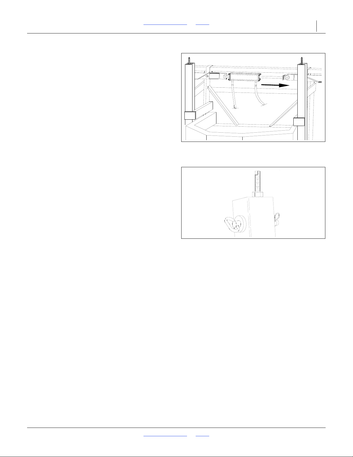
Refer to Figure 14
Put the transport pins in storage position. Slowly lower
the drill until it is on the ground and the main frame top
slide cylinder is fully extended. Pull the drill forward a few
feet to make sure that the transport and the gauge wheel
tires have equally firm contact with the soil.
Refer to Figure 15
Unfold the drill on a level seedbed typical to your soil
conditions.
At the top of both vertical tubes on the transport frame is
a threaded stud and jam nut. Make sure both studs have
approximately the same length of threads extending
above the jam nut (approximately 3 inches for most
planting conditions). Adjustments may be required.
2018-08-02 Table of Contents Index 155-015M-A
Page 28
2SF24 and 2SF30 Table of Contents Index 24
High Pressure Fluid Hazard:
Relieve pressure and shut down tractor before connecting,
disconnecting or checking hydraulic lines. Use a piece of
paper or cardboard, NOT BODY PARTS, to check for leaks.
Wear protective gloves and safety glasses or goggles when
working with hydraulic systems. Escaping fluid under pressure
can have sufficient pressure to penetrate the skin causing
serious injury. If an accident occurs, seek immediate medical
assistance from a physician familiar with this type of injury.
Operating Instructions
This section covers general operating procedures.
Experience, machine familiarity, and the following
information will lead to efficient operation and good
working habits. Always operate farm machinery with
safety in mind.
Pre-Start Checklist
Perform the following steps before transporting the
product to the field.
Carefully read “Important Safety Information” on
page 1.
Fertilizer Option: Review the application instructions
and Material Safety Data Sheet (MSDS) for the
fertilizer(s).
Lubricate drill as indicated under “Lubrication and
Scheduled Maintenance” on page 60.
Check all tires for proper inflation. See “Tire
Inflation Chart” on page 68.
Check all bolts, pins, and fasteners. Torque as
shown in “Torque Values Chart” on page 68.
Check drill for worn or damaged parts. Repair or
replace parts before going to the field.
Check hydraulic hoses, fittings, and cylinders for
leaks. Repair or replace before going to the field.
NOTICE
LIFT CYLINDERS OPERATING INSTRUCTIONS
This machine is equipped with rephasing master slave lift cylinders which
may after a period of time get out of time or phase. An indication of
this is when one section is running too low or too high because its lift
cylinder is either overextended or overetracted compared to the other lift
cylinders. To rephase the cylinders, raise the implement completely up and
hold the tractor hydraulic lever on for a few seconds giving the cylinders
time to rephase. This should be done each time the machine is raised out
of the ground. Momentarily reversing the hydraulic lever immediately after
rephasing to allow the cylinders to retract about 1/2” will help to maintain
a level implement.
818-043C Rev. A
2018-08-02 Table of Contents Index 155-015M-A
Page 29
2SF24 and 2SF30 Table of Contents Index Operating Instructions 25
General Notes for Field Operations
Most of the procedures described in this section require
the use of a tractor with hydraulic remotes. Before
proceeding with the first time setup, or before making
any adjustments mentioned in this section, make every
effort to obtain and hitch a tractor to the drill.
24 foot drill: minimum of 125 horsepower
30 foot drill: minimum of 150 horsepower
Negative Tongue Weight Hazard:
This drill can have both positive and Negative Tongue Weight
and it can change during planting. This poses a serious hazard
during unhitching and it can work the hitch pin loose during
transport. Never unhook from tractor with boxes unfolded and
raised off the ground.
Be certain that the drill tires have the proper inflation as
listed in the “Tire Inflation Chart” on page 68.
Load seed box with seed. Use clean seed to get the best
results. Always have the drill hitched securely to a tractor
with safety chain connected. Lower the drill before
loading.
This drill can be transported with a full box of grain. It is
best not to do this unless necessary because the
increased weight does increase the chances for
problems on the road. Do not exceed 20 miles per hour.
Calibrate each seed box for a proper rate based on the
seed that you are drilling. Calibration information is
located on the inside of your box lid or in the seed rate
book. Make sure the seed rate is adjusted the same
across the entire drill.
If your drill comes equipped with an acremeter, it should
be mounted on the left gauge wheel axle on the outboard
side. It will accumulate the total acres drilled with the drill.
In order to find out the acres covered, write down the
beginning reading and subtract it from the ending
reading for the total acres planted.
This drill is offered in different row spacings; therefore,
some of the drill boxes do not have the same number of
seed cups between each internal box divider. The
section with the largest number of cups will tend to empty
sooner.
Make sure that the seed-cup-door adjustment handles
are set the same across the drill.
If you notice excessive cracking on large-grain seeds,
adjust all seed cup door handles to a wider setting.
After lowering the drill into planting position, observe the
drill from the side. Check to see that the tongue is level to
the ground. If it is not, a hitch height adjustment is
needed. See “Tractor Draw Bar Hook-Up” on page 15.
It is especially important to check for this if the drill has
been hitched to a different tractor.
This drill is not designed to be turned sharply in the field.
Always lift the drill completely out of the ground when
turning at ends of field rows and other short-radius turns.
If the drill is not completely raised, the lift hydraulics will
be out of sequence. Refer to “Bleeding Hydraulic
Systems” on page 18.
Crushing Hazard:
Never allow anyone to ride on the drill.
Maximum seeding speed will vary according to soil
conditions.
You can adjust the tension on each disk spring. This is
especially useful in applying more pressure in tractor tire
tracks.
Equipment Damage Risk:
Do not lower drill while in folded position, certain equipment
damage will occur.
Machine Damage Risk:
Never back up with openers in the ground. If you do, check all
openers to be sure none are clogged.
2018-08-02 Table of Contents Index 155-015M-A
Page 30
2SF24 and 2SF30 Table of Contents Index Operating Instructions 26
Figure 16
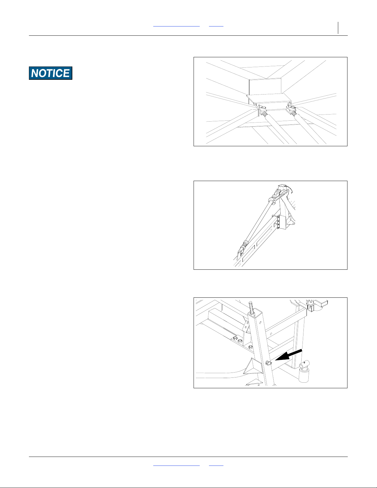
Transport Stabilizers in Road
Position
10673
Figure 17
Wing Adjustment Turnbuckle
10674
Figure 18
Transport Lock Pin in Transport
Position
17269
Folding the Drill
Equipment Damage Risk:
Do not lower drill while in folded position, certain equipment
damage will occur.
1. Folding is best achieved on level ground with the
tractor transmission in neutral. Be aware of the
clearance required to fold the drill.
2. NEVER allow anyone near the drill during folding
operations.
Refer to Figure 16
3. When folding the drill, the drill transport stabilizer
frame should line up with the nest on the front of the
main frame,
Refer to Figure 17
4. If the stabilizers scrape the wing on the tongue, the
boxes can be raised or lowered by adjusting the wing
adjustment turnbuckle.
Refer to Figure 18
5. Apply hydraulic pressure to the raising and lowering
system. Raising the drill may be required to free up
the transport lock pins in the vertical tubes for
removal. Place pins into transport position.
6. Fold boxes using hydraulic cylinders. Do this very
slowly and carefully. Serious damage could occur if
done fast and carelessly.
2018-08-02 Table of Contents Index 155-015M-A
Page 31
2SF24 and 2SF30 Table of Contents Index Operating Instructions 27
Figure 19
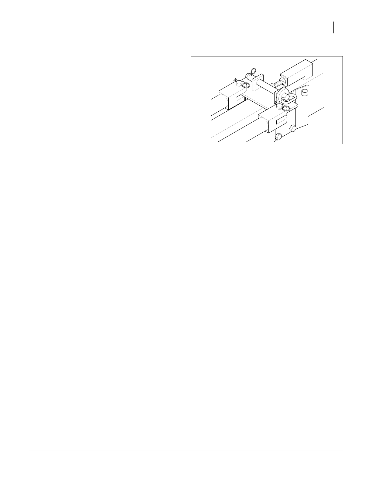
Pull Bar Pin Locked in Transport
Position
10739
Refer to Figure 19
7. Place the pin in the pull-bar transport lock. This must
always be used when transporting the drill in the
folded position.
Lifting the Drill
The lift cylinders may after a period of time get out of
time or phase. The effects of this can be seen when one
side of the drill is running too low or too high because its
lift cylinder is either overextended or not retracted
compared to the other lift cylinders.
To rephase the cylinders, raise the drill completely up
and hold the tractor hydraulic lever on for a few seconds
to give the cylinders time to rephase. This should be
done each time the drill is raised out of the ground.
Momentarily reversing the hydraulic lever immediately
after rephasing to allow the cylinders to retract about
1
/2inch will help in maintaining a level drill.
NOTE:
Understand that having the cylinders become
gradually out of time is different than having air
trapped in the system from improper bleeding. Each
condition is corrected differently.
2018-08-02 Table of Contents Index 155-015M-A
Page 32
2SF24 and 2SF30 Table of Contents Index Operating Instructions 28
Figure 20
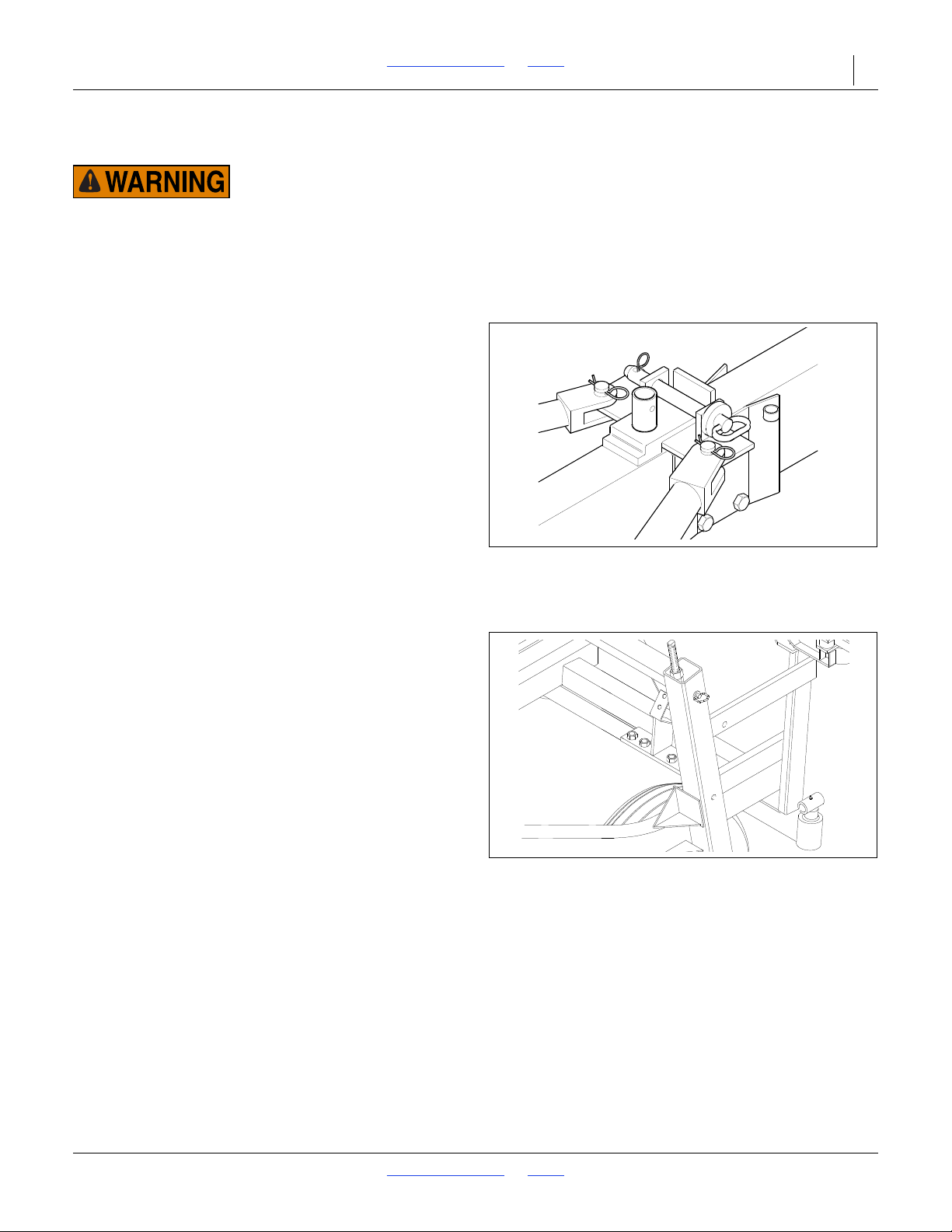
Pull Bar Lock Pin in Field Position
10730
Figure 21
Transport Lock Pin in Field Position
17268
Unfolding the Drill
Negative Tongue Weight Hazard:
This drill has a negative tongue weight when unfolded and
raised. Be certain that the drill is hitched securely to your
tractor drawbar and be certain the hitch safety chain is
securely attached to the drill hitch and tractor before raising
or unfolding the drill!
1. Unfolding the drill is best achieved on level ground
with the tractor transmission in neutral.
2. Be aware of the clearance requirements of the
unfolding drill. Allow plenty of room to unfold and DO
NOT allow anyone in the area of the drill when
unfolding.
Refer to Figure 20 and Figure 21.
3. Remove pin from pull-bar transport lock.
4. Slowly unfold the drill using the hydraulic cylinders.
For the first time, watch to be sure the hydraulic
hoses do not get pinched or kinked. Serious damage
could occur if the drill is unfolded carelessly.
5. Apply hydraulic pressure to the raising and lowering
system. Lowering the drill may be required to free up
the transport lock pins in the vertical tubes for
removal. Place pins into storage position.
2018-08-02 Table of Contents Index 155-015M-A
Page 33
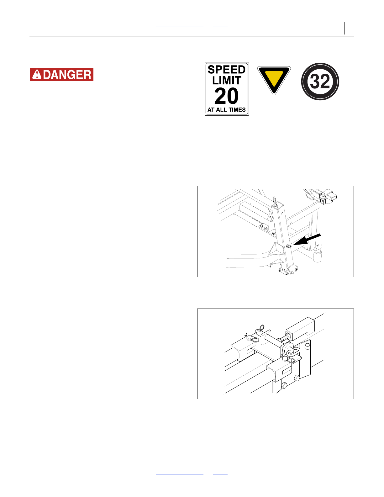
2SF24 and 2SF30 Table of Contents Index Operating Instructions 29
Figure 22
Transport Lock Pin in Transport
Position
17269
Figure 23
Pull Bar Lock Pin in Transport
Position
10739
Transporting the Drill
Loss of Control Hazard:
Never tow an implement that weighs more than 150% of the
tractor. Check your numbers. This drill is quite heavy for its
size. Ensure that the towing vehicle is adequate for the task.
Using an inadequate tow vehicle is extremely unsafe, and can
result in loss of control, serious injury and death. The drill can
weigh nearly 23000 pounds (10500 kg), depending on
configuration and material load. The tractor MUST be rated
for the load and must weigh at least 67% of the load. If the
tractor is not rated for at least 23000 lbs, calculate or obtain a
scale weight of the drill. See chart below for typical
configuration weights.
Do not tow if drill exceeds the load rating of the vehicle.
Before transporting drill
1. Make sure that hitch is securely attached to the draw
bar of the tractor and that the hitch safety chain has
been securely attached.
2. To prevent possible damage in case of hydraulic
failure during transport, Always insert transport lock
pins when transporting (see Figure 22).
3. Check to be sure the pull-bar transport lock pin is in
position (see Figure 23).
4. Check to see if you have the required air pressure in
your transport tires for proper inflation see “Tire
Inflation Chart” on page 68.
5. When in transport, use warning lights and safety
hitch chain. Comply with all federal, state and local
laws when traveling on public roads.
6. Be sure that the drill is properly folded. The drill
boxes must be correctly supported in the folded
position. “Folding the Drill” on page 26.
7. Reduce speed of the tractor when transporting over
uneven or rough terrain. Avoid all chuck holes and
washboard areas in roads.
8. Reduce speed of the tractor when transporting over
hills or steep slopes. NEVER exceed 20 miles per
hour.
9. Use slow moving vehicle emblem for warning
vehicles approaching from the rear.
10. When transporting, remember the drill is wider than
your tractor and extreme care must be taken to allow
for safe clearance.
11. Extra care should be taken when transporting with
seed in the box.
2018-08-02 Table of Contents Index 155-015M-A
Page 34
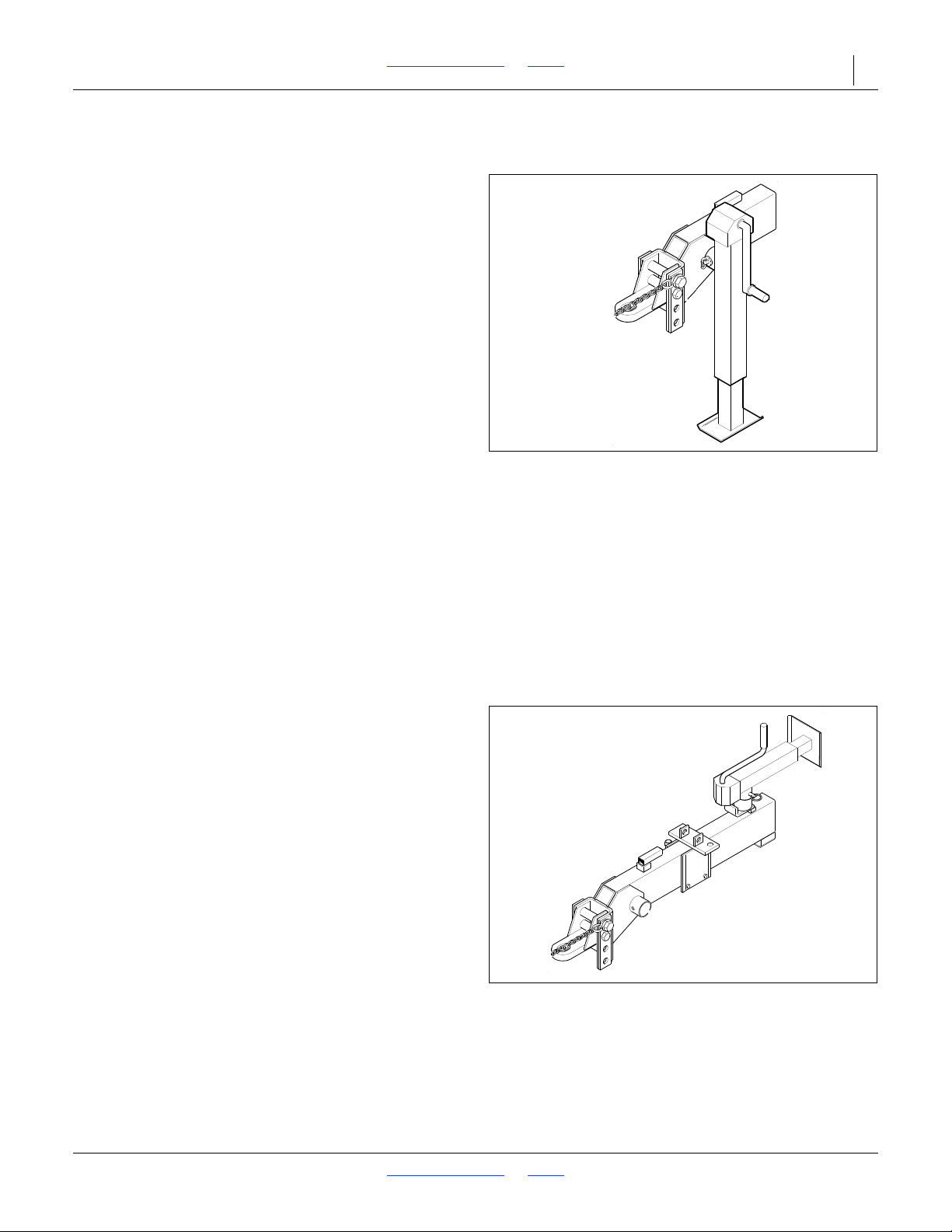
2SF24 and 2SF30 Table of Contents Index Operating Instructions 30
Figure 24
Jack in Vertical Position
10739
Figure 25
Jack in Transport Position
10739
Parking
1. Choose a location with level firm ground. Do not
unhitch on a steep slope.
2. Fold drill (page 26).
3. Set hydraulic circuits to neutral.
4. Disconnect hydraulic lines. Secure them so that they
do not touch the ground.
5. Disconnect electrical cables, capping where
provisioned.
6. Move jack from storage position to side of tongue
(see Figure 24).
If the ground is soft, place a board or plate under the
jack to widen the ground contact area.
7. Slightly raise tongue with jack until the weight of the
tongue is on the jack and has been removed from
the tractor drawbar.
8. Remove the hitch pin and safety chain from the
tractor drawbar.
9. Restart tractor and pull away from drill.
The following steps should be done when preparing to
hitch the drill to the tractor.
10. Raise or lower the drill tongue as needed and hitch
the drill to the tractor drawbar. Always use a safety
chain, see “Tractor Draw Bar Hook-Up” on
page 15.
11. Plug the drill hydraulic lines into the tractor remotes.
12. Connect the electrical cables.
13. Retract the jack until the weight of the tongue and pin
it on the storage post located on top of the main
tongue (see Figure 25).
NOTE:
If the drill is being hitched up and operated for the first
time, it is important to follow the safety, setup,
adjustment, bleeding, and operating information.
2018-08-02 Table of Contents Index 155-015M-A
Page 35
2SF24 and 2SF30 Table of Contents Index Operating Instructions 31
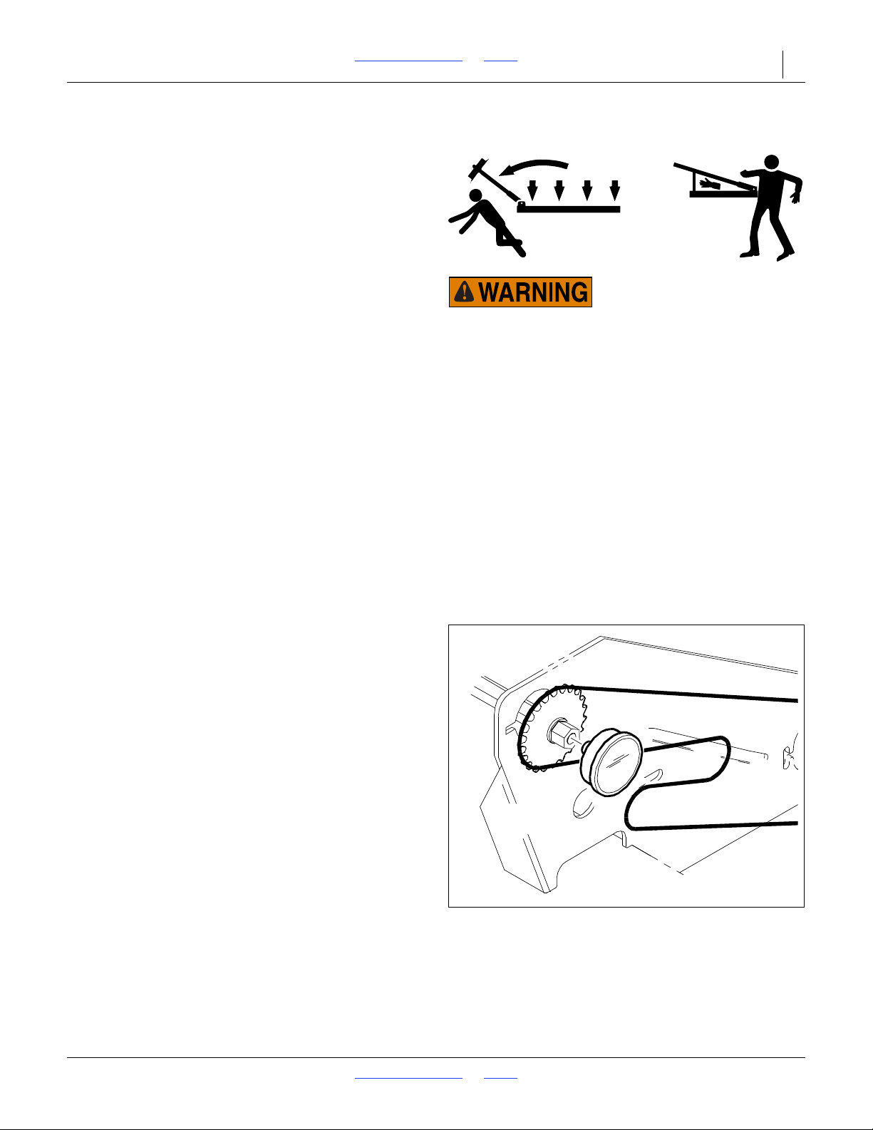
Overhead, Crushing and Sharp Object Hazards:
Do not allow anyone to stand under, near or beyond the end of
opener frame during marker operations. There is risk of
serious injury or death for anyone under the frame or in the
path of a marker. Marker arms are heavy, are under
tremendous hydraulic power, and may move suddenly if the
hydraulic system is damaged or needs bleeding. Marker discs
may be sharp.
Figure 26
Electronic Acremeter Installation
27000
Marker Operations
It is not possible to operate the markers other than during
a field lift or field lower. If the Lift/Lower steps are
followed, one marker alternately folds on one side at each
lift, and the other unfolds at each lower.
Dual Marker Operations
It is possible to deploy markers on both sides. This might
be needed for special field passes, but can also occur
inadvertently if a lift/lower is interrupted.
Two Markers Out
1. Perform a normal field lower/marker deploy (previous
topic).
2. When the lowering stops, with the marker fully
unfolded, briefly reverse the lever to Extend (lift), then
back to Retract (lower).
3. The marker on the opposing side deploys. Hold at
Retract until the marker is fully unfolded.
Folding From Two Markers Out
With two markers out, the next lift operation folds only
one of them (the second one deployed). To fold the other
marker, use either of two techniques:
• Perform a second lower, then a lift, or
• At full fold of the first marker, perform a brief Extend,
then a Retract, to fold the other marker (and continue
frame lift).
Acremeter
Refer to Figure 26
The acremeter is factory installed. It is located on the left
end of the left main drive shaft.
If the acremeter has been removed, screw the threaded
end of the meter into the
end of center main drive shaft.
Tighten the threaded end only enough to prevent it from
working loose from normal vibration. In use, there is no
torque or tension that might tend to unscrew it.
1
/2-20 tapped hole in the left
2018-08-02 Table of Contents Index 155-015M-A
Page 36
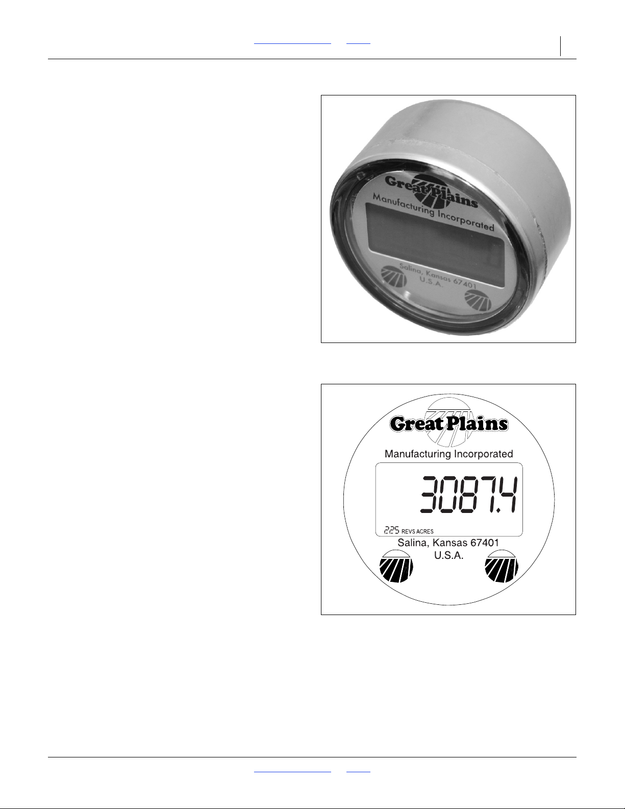
2SF24 and 2SF30 Table of Contents Index Operating Instructions 32
Figure 27
Electronic Acremeter
27378
Figure 28
Meter Display
36139
The acremeter counts shaft rotations whenever the shaft
is rotating - this is with the drill lowered and in motion or
during calibration crank operation. The meter is
programmed to display rotations as acres or hectares,
when using all rows, factory-specified tires and tire
inflations.
Unusual conditions and/or non-standard row spacings
can cause the acremeter tally to vary somewhat from
actual acres planted.
Normal Operating Sequence
The acremeter counts rotations during drill calibration
(and if so, can be useful for calibration, although the
meter must be on, or moved to the shaft being cranked).
1. Record the acremeter reading at the start of planting
(and after calibration). The large 12345.6 format
display is the grand total area planted since meter
installation. The smaller number in the lower left
corner is the number of revolutions per acre for
which the meter was factory-programmed. If the
display is blank, see “Dormant Display” below.
2. Lower drill and plant. Acremeter counts shaft
rotations, calculates acres or hectares, and adds to
the running grand total.
During planting (drill lowered and moving forward),
the display blanks (goes dormant), but area tally
continues.
When raised for turns, obstructions and transport,
the drill’s ground drive wheel, contact wheel or clutch
disengages the drive shaft, and the meter counts no
additional (non-planting) rotations.
Whenever shaft rotation stops, the LCD display
activates after 30 to 60 seconds, and remains visible
for 30 to 45 minutes.
3. At the completion of planting, record the final reading
of the grand total. If the display goes dormant before
you can read it, see “Dormant Display”.
4. Subtract the reading at Step 1 from the reading at
Step 6 for the total planted in the present session.
Dormant Display
To conserve power, the LCD display blanks itself most of
the time. If you need to read the display after if has
"timed out" and gone dormant:
• use the calibration crank to turn the jackshaft once,
or
• gently tap or wave a magnet at either of the Great
Plains logo spots on the lower region of the display.
Be careful not to scratch the window.
2018-08-02 Table of Contents Index 155-015M-A
Page 37
2SF24 and 2SF30 Table of Contents Index Operating Instructions 33
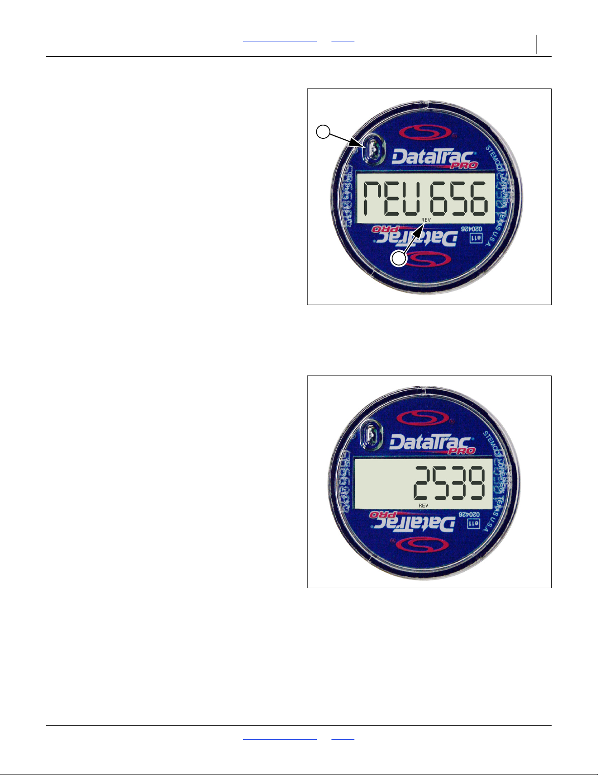
Figure 29
Check Program
34938
2
1
Figure 30
Typical Area Display
34939
DataTrac Acremeter
The DataTrac acremeter is factory installed on new units
(effective July 1, 2013). The meter is supplied with a
decal located on its side indicating the number of
programmed wheel revolutions.
The numbers automatically orient to read upright.
The acremeter always shows “REV” (1) on the face of
the display. The meter is programmed to count acres if
the drill is for domestic use and is programmed for
hectares if the drill is for export use.
Normal Operating Sequence
To display the number of revolutions per acre or hectare
programmed into the meter simply cover the round bump
on the face of the unit (light sensor) (2) with the palm of
your hand and leave it there for at least
removing it. A screen that shows “rEV ###” will be
displayed. The ### is the number of revolutions that is
programmed into the unit.
The acremeter may count rotations during drill calibration
(and if so, can be useful for calibration).
1
/2 second before
1. Record the acremeter reading at the start of planting
(and after calibration). The large “123456” format
display is the grand total area planted since meter
installation.
2. Lower drill and plant. The acremeter counts shaft
rotations, calculates acres or hectares, and adds to
the running grand total.
When raised for turns, obstructions and transport,
the drill’s ground drive wheel, contact wheel or clutch
disengages the drive shaft, and the meter counts no
additional (non-planting) rotations.
3. At the completion of planting, record the final reading
of the grand total.
4. Subtract the reading at Step 1 from the reading at
Step 3 for the total planted in the present session.
Dormant Display
If the display is totally blank and never displays anything,
the battery may be dead. Expected life is 5 to10 years.
The battery is not user-replaceable.
2018-08-02 Table of Contents Index 155-015M-A
Page 38

2SF24 and 2SF30 Table of Contents Index Operating Instructions 34
Long-Term Storage
1. Clean the drill as necessary. Be sure that the seed
boxes, fertilizer box and all feed systems are
completely cleaned out before storing.
2. Lube chain and adjust all roller chains.
3. Lubricate all fittings as indicated in “Maintenance
and Lubrication” on page 57.
4. When storing in transport position, use all locking
devices as described under “Transporting the Drill”
on page 29 and “Operating Instructions” on
page 24.
5. Apply a light coat of grease to all exposed hydraulic
cylinder rods.
6. Seed cup drive sprocket hub should be oiled in its
square bore. Squirt oil on to the square seed cup
shaft and move seed cup adjustment lever back and
forth in order to get the oil back into the square. This
is most important before putting the drill in storage.
7. Always maintain proper pounds of air pressure in
gauge wheel tires and in transport tires see “Tire
Inflation Chart” on page 68.
8. Store the drill inside if possible. Inside storage will
reduce maintenance and make for a longer drill life.
2018-08-02 Table of Contents Index 155-015M-A
Page 39
2SF24 and 2SF30 Table of Contents Index 35
Adjustments
To get full performance from the 2SF24 or 2SF30 drill,
you need an understanding of all component operations,
and many provide adjustments for optimal field results.
Even if your planting conditions rarely change, some of
these items need periodic adjustment due to normal
wear.
Some of these have been covered earlier in this manual.
Adjustment Page The Adjustment Affects
Planting Depth Adjustment 36
Press Wheel-Opener Linkage Depth Adjustment 36 Consistent seed firming and planting depth
Seeding Adjustments 37 Seeding rate and size
Small Seeds Attachment 45 Small seeds population
Fertilizer Meter Rate 48 Control of application rate
Marker Adjustments 50 Correctly offset and visible pass marks
Disk Scraper Adjustments 53 Keep opener disks turning freely
Seed Firmer Adjustments 53 Consistent seed placement and coverage
Leveling
Opener Spring Rods 20 Uniform down pressure on press wheels and openers
Transport Wheels 21 Controls lift cylinder travel for accurate seed depth
Gauge Wheels 22 Levels ends of drill with the center
Box Adjustments 22
Pull Bar 22
Top Slide 22 Helps to make adjustments to the pull bars
Seeding Adjustments
Main Box Rate 37 Correct sprocket arrangement for seed type
Seed Cup Handle 38 Correct position of handle for seed size
Fertilizer Rate 48 Proper metering rate for field conditions
Small Seeds Rate 45 Match sprocket arrangement with drive type
Ensure drill boxes are in line with one another and
parallel to the main frame for uniform seeding
2018-08-02 Table of Contents Index 155-015M-A
Page 40
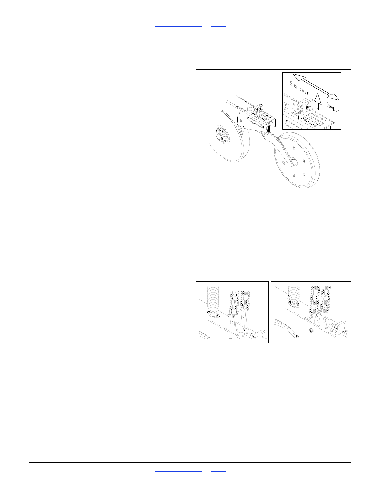
2SF24 and 2SF30 Table of Contents Index Adjustments 36
Figure 31
Direct Link Press Wheel Adjustment
12100
Figure 32
Maximum (left) and Minimum (right)
Pressure
12102
12103
Planting Depth Adjustments
Press Wheel-Opener Linkage Depth
Adjustment
Attached to the rear of each these openers is one of
several optional press wheels. The press wheel and its
mechanism provide two important functions:
1. The press wheel closes the furrow and gently
presses the soil over the seed.
To provide consistent seed firming, the press wheel is
free to move downward from its normal operation
position. This system maintains pressing action even if
the opener body is lifted as a result of the opener disks
encountering an obstruction or hard soil.
2. The press wheel rolls on the ground providing depth
control to the opener and seed.To maintain a
consistent planting depth, the relationship between
the bottom of the opener disk-blades and the press
wheel is upwardly fixed. The upward stop is
independently adjustable on each opener. The
position of the adjustable stop determines how deep
the seed will be placed.
Refer to Figure 31
To change the height of the press wheel, which
automatically changes the seeding depth of the opener,
simply lift the "T" handle located on top of the opener at
the rear and slide forward or rearward until the seeding
depth is correct as shown in the inset in. A spring loaded
pin holds the "T" handle at your setting to maintain the
proper depth.
Disk Opener Spring Pressure Setting
Refer to Figure 32
Each opener spring can be adjusted for down pressure.
This is useful when penetrating hard soil and for planting
in tractor tire tracks. To adjust the pressure, remove the
"W" clip at the bottom of the spring and place it in a
higher hole in the spring rod for more pressure, and in a
lower hole for less pressure.
2018-08-02 Table of Contents Index 155-015M-A
Page 41

2SF24 and 2SF30 Table of Contents Index Adjustments 37
Seeding Adjustments
1. Raise outboard ends of drill boxes high enough to lift
the end wheels off the ground. Rotate gauge wheel
to see that seed cups and drive are working properly,
not binding and free from foreign material.
2. To adjust your seeding rate, first you must decide
which sprocket arrangement you need (see seeding
charts on next pages).
a. To change sprockets, remove nut on the double
speed change sprocket and turn sprocket over.
b. Loosen the idler arm bolt, put chains on and
tighten both bolts. (The lengths of the chains will
need to be adjusted in order to make this
change.)
There are many factors which will affect seeding rates,
including seed treatment, weight of seed, size of seed,
surface condition of seed, and tire configuration,
pressure and slippage. Minor adjustments will probably
be needed to compensate for these factors.
The pounds-per-acre in the seed charts are based on
drills having 9.5L X 15 inch implement gauge wheel tires.
The large differences in seed size and treatment can
cause a wide variation in actual seeding rates. The seed
rate charts on the following pages are based on average
size seed. This may differ from the seed you are using.
Use the seed rate chart as a guide.
Set the pounds-per-acre desired at the indicator number
for your row spacing and complete the following
procedure to calibrate the drill for your specific seed.
a. Place several pounds of seed over three of the
seed cups at the outboard end of the drill box.
b. Pull the seed tubes off of these three disk
openers
c. Raise the drill off the ground.
d. Place a container under the three seed tubes to
gather the seed as it is metered.
e. Rotate the drive gauge wheel until one acre has
been tallied on the acremeter.
This will be approximately 225 rotations on a 24
foot drill and approximately 182 rotations on a 30
foot drill.
Be sure to check the three seed cups to make
sure each cup has plenty of seed coming into it.
f. Weigh the seed which has been metered. Divide
by three. This will give you the ounces/pounds
metered by each seed cup.
Multiply by the number of openers on your drill to
arrive at the total pounds-per-acre your drill
would meter at that setting.
If the seeding rate is different than desired, set
your seed cup adjustment lever accordingly.
Repeat step a through step f on each drill section.
You may want to repeat the calibration procedure if the
results of your calibration vary greatly from the
suggested setting contained in this manual.
Tire size and field conditions will also affect seeding
rates. Be certain that your drill tires are 9.5L x 15" and
that they have the proper inflation.
When drilling, check the amount of seed you are using
by noting acres drilled, amount of seed added to drill,
and level of seed in drill box.
If you suspect that you are drilling more or less than
desired, and you have accurately calibrated the drill to
your seed, you may need to adjust the seeding rate
slightly to compensate for your field conditions.
NOTE:
This drill is equipped with four-position feed cup door
on each feed cup. The highest handle position is for
wheat and other small grain seeds, the second
handle position is for soybean and other large grain
seeds. Should excessive cracking occur to the large
seeds, drop the handle to the third position. The
wide-open position will allow complete clean out of
the feed cup. Make sure all handles are in the same
position before drilling.
NOTE:
Do not open the cup up to the wide-open position
with seed in the box unless complete clean out is
desired.
2018-08-02 Table of Contents Index 155-015M-A
Page 42
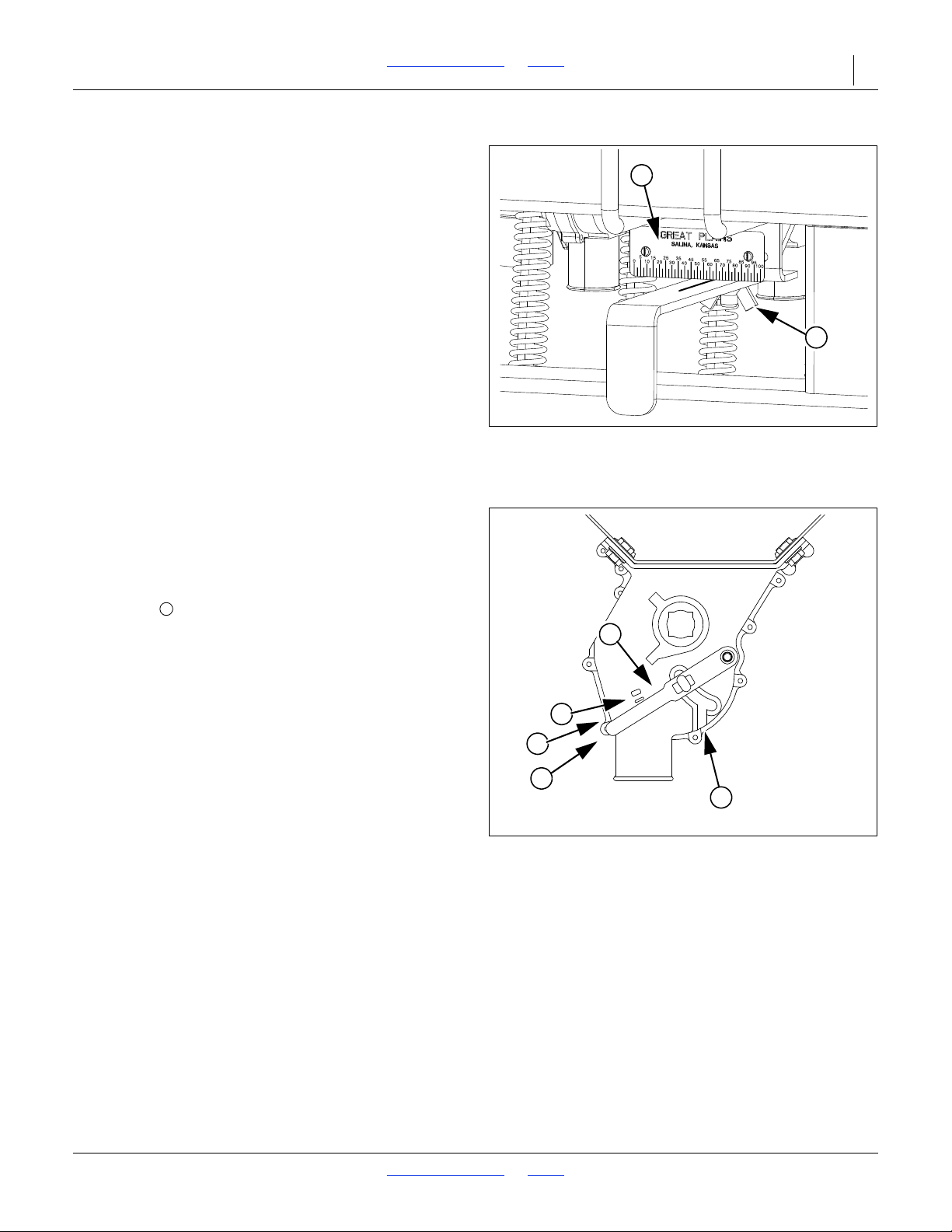
2SF24 and 2SF30 Table of Contents Index Adjustments 38
Figure 33
Seed Rate Handle
36150
1
2
Figure 34
Seed Cup Door Handle
?????
1
2
3
4
5
4
Main Box Seed Rate Handle
Refer to Figure 33
There are main box seed rate handles for each section of
the drill (2 handles total). Generally, they need to be set
identically, and you need to calibrate only one section.
The seed rate handle controls the percent engagement
of the seed sprocket in each seed cup. The initial setting
of the handle is given by the Seed Rate Chart.
You can temporarily stop seed flow to a drill section by
setting a handle to zero.
To set a handle:
1. Loosen wing nut (1) under handle.
2. Move indicator (2) from current setting to about 10
past the new desired value from calibration or the
Seed Rate Chart, then move it back to the new
desired value.
3. Tighten wing nut.
Position Seed Cup Doors
Refer to Figure 34
which depicts the seed cup door handle in position
(3).
At each main seed box seed tube, adjust the seed cup
door handle for the seed size.
The handle has three normal operating position detents:
(top detent) is for the smallest seeds.
(1)
Use it for wheat and similar small seeds.
(middle detent) is for larger seeds.
(2)
Use it for soybeans and similar larger seeds.
(bottom detent) is for oversize or fragile seeds.
(3)
If you experience excessive cracking with setting (2),
use setting (3).
NOTE:
Handle position (5) is used for cleanout, not planting.
If set to this position with seed loaded, it may be
difficult to reset it to a normal operating position.
2018-08-02 Table of Contents Index 155-015M-A
Page 43
2SF24 and 2SF30 Table of Contents Index Adjustments 39
ALFALFA OR RAPE
SEED RATE INDICATOR SETTING NUMBER
DRIVE TYPE 2 0 5 10 15 20 25 30 35404550556065707580 859095100
Row Spacing Pounds Per Acre
6 in. 0 4 6 8 11 14 17 20 23 26 29 32 35 3740424547505254
7 in. 0 3 571013 15 18 20 23 25 2830 32 34 37 394143 45 46
7 1/2 in. 0 3 5 7 9 12 14 16 18 21 23 26 2830 32 34 36 38 40 41 43
8 in. 0 3 468 11 13 15 17 19 22 24 26 27 29 31 33 35 36 38 39
10 in. 0 2 3 5 7 9 10 12 14 16 18 19 21 22 24 25 27 2830 31 32
BARLEY
SEED RATE INDICATOR SETTING NUMBER
DRIVE TYPE 1 0 5 10 15 20 25 30 35404550556065707580 859095100
Row Spacing Pounds Per Acre*
6 in. 0 0 7 14 20 27 33 394450556268 75 82 88 93 99 102 105 107
7' 0 0 6 12 18 23 2834 38 44 48 54 59 65 71 76 81 86 88 91 93
7 1/2 in. 0 0 6 11 16 21 26 31 3640445055606670757981 84 86
8 in. 0 0 5 10 15 20 24 28333740465055606468 73 75 77 79
10 in. 0 0 4 8 12 16 20 23 27 30 33 3741454953 56 59 61 63 64
* Based on 46.4 pounds per bushel
BUCKWHEAT
SEED RATE INDICATOR SETTING NUMBER
DRIVE TYPE 1 0 5 10 15 20 25 30 35404550556065707580 859095100
Row Spacing Pounds Per Acre
6 in. 0 8 14 20 26 33 40 47 55 62 70 77 85 94 102 111 118 124 128 134138
7 in. 0 7 121722293440475461677381 88 97 102 107 111 116 120
7 1/2 in. 0 6 1116212632 374450566268 75 82 899499102107111
8 in. 0 6 1015192429344045515762697582 86919498 101
10 in. 0 5 8 12 15 20 24 28333742465156616771747780 83
FLAX OR SUDAN
SEED RATE INDICATOR SETTING NUMBER
DRIVE TYPE 2 0 5 10 15 20 25 30 35404550556065707580 859095100
Row Spacing Pounds Per Acre
6 in. 02469121416192124262932 35 38 42 45 47 47 48
7 in. 0 2 3 5 8 10 12 14 16 18 21 23 25 2830 33 36 39414141
7 1/2 in. 0 2 3 5791113 15 17 19 21 23 26 2830 33 36 37 38 38
8 in. 0 1 3 5 7 9 10 12 14 16 17 19 21 23 26 2831 33 34 35 35
10 in. 0124578 10 11 13 14 16 18 19 21 23 25 27 28 28 29
Seed Rate Charts: U.S. Customary Units
2018-08-02 Table of Contents Index 155-015M-A
Page 44
2SF24 and 2SF30 Table of Contents Index Adjustments 40
MILLET
SEED RATE INDICATOR SETTING NUMBER
DRIVE TYPE 2 0 5 10 15 20 25 30 35404550556065707580 859095100
Row Spacing Pounds Per Acre
6 in. 0 3 5 7 10 12 15 18 21 24 26 30 32 36 3943 47 50 52 53 53
7 in. 02468 11 13 16 18 21 23 26 2831 34 374043 45 46 46
7 1/2 in. 0 2 4 6 8 10 12 14 17 19 21 24 26 29 31 34 3740424242
8 in. 0 2 3 5791113 15 17 19 22 24 26 29 31 34 36 38 39 39
10 in. 0 2 3 46791113 14 16 18 19 21 23 26 2830 31 32 32
MILO
SEED RATE INDICATOR SETTING NUMBER
DRIVE TYPE 2 0 5 10 15 20 25 30 35404550556065707580 859095100
Row Spacing Pounds Per Acre*
6 in. 0 3 5 8 12 15 18 21 24 27 30 34 374145495457606061
7 in. 0 2 4 7 10 12 15 18 21 24 26 29 32 36 39424650525253
7 1/2 in. 024691114161922242730 33 36 3943 46 48 48 49
8 in. 0 2 3 6 8 10 13 15 18 20 22 25 27 30 33 36 3942444445
10 in. 0 2 3 5 7 9 11 12 14 16 18 20 22 25 27 29 32 34 36 36 37
* Based on 62.4 pounds per bushel
OATS OR SAFFLOWER
SEED RATE INDICATOR SETTING NUMBER
DRIVE TYPE 1 0 5 10 15 20 25 30 35404550556065707580 859095100
Row Spacing Pounds Per Acre*
6 in. 0 4 8 14 19 25 31 3744515764717683 90 96 102 107 112 116
7 in. 0 4 7 12 16 22 27 32 38 44 49 55 61 66 72 78838893 97 100
7 1/2 in. 0 3 7 111520252935414551576167727781 85 8993
8 in. 0 3 6 10141923 27 32 3741475256616670757882 85
10 in. 0 3 5 8 11 15 19 22 26 31 34 38 42 46 50 54 58 61 64 67 70
* Based on 39 pounds per bushel
PEAS
SEED RATE INDICATOR SETTING NUMBER
DRIVE TYPE 1 0 5 10 15 20 25 30 35404550556065707580 859095100
Row Spacing Pounds Per Acre
6 in. 0 0 102641557082 95 110 123 135 150 163 176 189 204 215 227 235241
7 in. 0 0 8 233548 61 71 82 96 107 117 130 141 152 164 177 186 197 204 209
7 1/2 in. 0 0 8 21 33 44 56 66 76 88 99 108 120 130 140 151 163 172 182188 193
8 in. 0 0 7 19 304051606981 90 99 110 120 129 139149158 167 172 177
10 in. 0 0 6 16 24 33 42 49 57 66 74 819098 105 113 122 129 136141145
2018-08-02 Table of Contents Index 155-015M-A
Page 45
2SF24 and 2SF30 Table of Contents Index Adjustments 41
PINTO BEANS
SEED RATE INDICATOR SETTING NUMBER
DRIVE TYPE 2 0 5 10 15 20 25 30 35404550556065707580 859095100
Row Spacing Pounds Per Acre*
6 in. 00047121620242832 36414448 53 56 60 63 64 65
7 in. 0 0 0 3 6101418 21 24 27 31 35 38 42 46 49 52 55 55 56
7 1/2 in. 0 0 0 3 6913 16 19 22 25 29 32 35 39424548 50 51 52
8 in. 0 0 0 3 5 9 12 15 18 20 23 27 30 32 35 394144464747
10 in. 00024710121417192224272932 34 36 38 38 39
* Based on 60.35 pounds per bushel
RICE LONG GRAIN
SEED RATE INDICATOR SETTING NUMBER
DRIVE TYPE 1 0 5 10 15 20 25 30 35404550556065707580 859095100
Row Spacing Pounds Per Acre
6 in. 0 6 101520252934 3944495458 64 73 79 859193 97 100
7 in. 0 5 9 13 17 21 25 30 34 38 42 47 50 56 63 69 74 7881 84 87
7 1/2 in. 0 5 8 12 16 20 23 2831 35 3943 46 51 59 63 98 72 74 7880
8 in. 0 4 8 11 14 18 21 25 29 32 364042475458 63 66 68 71 74
10 in. 0 4 6 9 12 15 17 21 23 26 29 32 35 39444751545658 60
RICE LONG GRAIN
SEED RATE INDICATOR SETTING NUMBER
DRIVE TYPE 1A 0 5 10 15 20 25 30 35404550556065707580 859095100
Row Spacing Pounds Per Acre
6 in. 0 12 21 314050607180 91 100 110 119 132 150 162 175 185 191 200 206
7 in. 0 11 19 27 3544526169788796103 114 130 141 152 160 165 173 179
7 1/2 in. 0 10 17 25 324048 57 64 72 80 89 95 105 120 130140148 153 160 165
8 in. 0 9 16 23 29 37445259667481 87 97 110 119 129 135 140 146 151
10 in. 0 7 13 18 24 30 364248 54 60 66 71 79 90 97 105 111 115 120 124
RICE SHORT GRAIN
SEED RATE INDICATOR SETTING NUMBER
DRIVE TYPE 1 0 5 10 15 20 25 30 35404550556065707580 859095100
Row Spacing Pounds Per Acre
6 in. 0 7 13 18 2330 354246515762667483 90 98 103 107 112 115
7 in. 0 6 1116202631 36 3 944495457647278859093 97 100
7 1/2 in. 0 6 1014192428333641455053 59 66 72 7883859092
8 in. 0 5 9 13 17 22 26 31 33 3741464955616672767882 85
10 in. 0 4 8 11 14 18 21 25 27 31 34 37404550545962646769
2018-08-02 Table of Contents Index 155-015M-A
Page 46
2SF24 and 2SF30 Table of Contents Index Adjustments 42
RICE SHORT GRAIN
SEED RATE INDICATOR SETTING NUMBER
DRIVE TYPE 1A 0 5 10 15 20 25 30 35404550556065707580 859095100
Row Spacing Pounds Per Acre
6 in. 0 15 26 3748 61 738593 104 116 128 136153 169 185 201 212 219 230237
7 in. 0 13 23324253 63 74 81 91 101 111 118 132 147 160 175 184 190 199 205
7 1/2 in. 0 12 21 30 394958 68 75 8493 103 109 122 136148 161 170 175 184189
8 in. 0 11 19 27 354553 63 69 77 85 94 100 112 124 136148 156 161 169 174
10 in. 0 9 162229
3744515663 70 77 81 92 102 111 121 127 132138 142
RYE
SEED RATE INDICATOR SETTING NUMBER
DRIVE TYPE 2 0 5 10 15 20 25 30 35404550556065707580 859095100
Row Spacing Pounds Per Acre
6 in. 0 3 6 8 11 14 16 18 20 23 25 2830 33 36 38 40 42 43 46 47
7 in. 0 3 5791213 16 18 20 22 24 26 29 31 33 35 36 38 40 41
7 1/2 in. 0 3 5 7 9 11 12 14 16 18 20 22 24 27 29 31 32 34 35 36 38
8 in. 02468 10 11 13 15 17 19 20 22 24 26 28 29 31 32 33 34
10 in. 024578 9 111214151718 20 21 23 24 25 26 27 28
SOYBEANS
SEED RATE INDICATOR SETTING NUMBER
DRIVE TYPE 1 0 5 10 15 20 25 30 35404550556065707580 859095100
Row Spacing Pounds Per Acre*
6 in. 0000304055708498 113 127 140 154 166 176 188 200 204 207 209
7 in. 0 0 0 0 26 3548 61 72 8598 110 122 133 144 153 163 173 177 180181
7 1/2 in. 0 0 0 0 24 324456677991101112123 132 141 150 160 164 166 167
8 in. 000022304051617283 93 103 113 121 129 138 147 150 152 153
10 in. 0 0 0 0 18 24 33 42 50 59 68 76 84 92 99 106 113 120 123 124 125
* Based on 59.1 pounds per bushel
SOYBEANS
SEED RATE INDICATOR SETTING NUMBER
DRIVE TYPE 2 0 5 10 15 20 25 30 35404550556065707580 859095100
Row Spacing Pounds Per Acre*
6 in. 0 0 0 0 10 13 18 23 27 32 37414650545761656768 68
7 in. 00008 11 16 20 24 2832 364043 47 50 53 57 58 59 59
7 1/2 in. 0 0 0 0 8 11 14 18 22 26 30 33 374043 46 49 52 53 54 55
8 in. 000071013 17 20 24 27 30 34 3740424548 49 50 50
10 in. 000068 11 14 16 19 22 25 27 30 32 34 37 39404141
* Based on 59.1 pounds per bushel
2018-08-02 Table of Contents Index 155-015M-A
Page 47
2SF24 and 2SF30 Table of Contents Index Adjustments 43
SOYBEANS
SEED RATE INDICATOR SETTING NUMBER
DRIVE TYPE 2A 0 5 10 15 20 25 30 35404550556065707580 859095100
Row Spacing Pounds Per Acre*
6 in. 0 0 0 0 20 27 37475666768594103 111 118 126 134137139140
7 in. 0 0 0 0 17 2332414957667381 8996103 110 116 119 121 122
7 1/2 in. 0 0 0 0 16 22 30 374553 61 68 75 82 89 95 101 107 110 111 112
8 in. 0 0 0 0 15 20 27 344148 56 62 69 75 82 8793 98 101 102 103
10 in. 0 0 0 0 12 16 22 2834404551566267717680 82 84 84
* Based on 59.1 pounds per bushel. Setting the feed cup adjustment lever between 50 & 80 allows for optimum seeding of soybeans.
SUNFLOWERS
SEED RATE INDICATOR SETTING NUMBER
DRIVE TYPE 2 0 5 10 15 20 25 30 35404550556065707580 859095100
Row Spacing Pounds Per Acre*
6 in. 00023 468 9 11141517192023 24 26 27 28 29
7 in. 000233578 10 12 13 15 16 18 20 21 22 23 24 25
7 1/2 in. 0 0 0 1 33568 9 111214151618 19 21 21 22 23
8 in. 000123 5678 10 11 12 14 15 17 18 19 20 20 21
10 in. 000123 45678 9 101112141415161717
* Based on 28.9 pounds per bushel
WHEAT
SEED RATE INDICATOR SETTING NUMBER
DRIVE TYPE 1 0 5 10 15 20 25 30 35404550556065707580 859095100
Row Spacing Pounds Per Acre*
6 in. 0 11 20 28374755657585 96 106 116 129 140 153 161 170 175 184189
7 in. 0 10 17 24 324048 56 65 738392 100 111 121 132 140 147 152 159 164
7 1/2 in. 0 9 16 23 29 3744526068 77 8593 103 112 122 129 136 140 147 152
8 in. 0 8 15 21 27 344048 55 62 70 788594103 112 118 124 129 135139
10 in. 0 7 121722283339455158 64 70 77 84 92 97 102 105 110 114
* Based on 60 pounds per bushel
WHEAT
SEED RATE INDICATOR SETTING NUMBER
DRIVE TYPE 2A 0 5 10 15 20 25 30 35404550556065707580 859095100
Row Spacing Pounds Per Acre*
6 in. 0 8 13 19 25 31 3744505764717886 94 102 108 114 117 123 127
7 in. 0 7 1116212732 38 44 46 56 62 67 75 81 899499102107110
7 1/2 in. 0 6 1115202530 354045525762697582 86919499102
8 in. 0 6 101418 23 27 32 374247525763 69 75 79 83 869093
10 in. 0 5 8 11 15 19 22 26 30 34 3943 47 52 56 61 65 68 70 74 76
* Based on 60 pounds per bushel
2018-08-02 Table of Contents Index 155-015M-A
Page 48
2SF24 and 2SF30 Table of Contents Index Adjustments 44
WHEAT GRASS
SEED RATE INDICATOR SETTING NUMBER
DRIVE TYPE 2 0 5 10 15 20 25 30 35404550556065707580 859095100
Row Spacing Pounds Per Acre
6 in. 01223 445678 9 9 10 11 12 13 14 14 15 15
7 in. 01123345567889 101111121213 13
7 1/2 in. 011223 445667889 101011111212
8 in. 0112233445667889 1010101111
10 in. 011122334455667788999
2018-08-02 Table of Contents Index 155-015M-A
Page 49
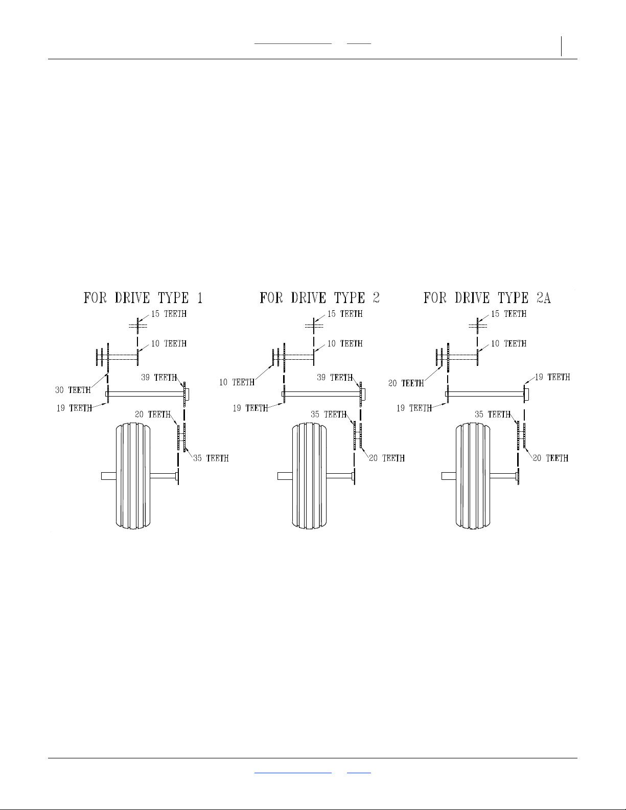
2SF24 and 2SF30 Table of Contents Index Adjustments 45
Figure 35
Small Seeds Sprocket Arrangements
16399
Small Seeds Attachment
To calibrate the seeding rate on the optional small seeds
attachment, follow these steps.
Refer to Figure 35
1. The proper small-seeds sprocket arrangement given
different drive types on the main drill box. Arrange
the sprockets on the small-seeds attachment
according to which drive type you will use on the
main drill box.
NOTE:
For accurate metering on the small seeds
attachment, the main drill box sprockets must be set
to drive type 1, 2 or 2A.
2. Set the seed-rate adjustment handle on the small
seeds attachment as indicated by the charts, “Small
Grass Seed Charts” beginning on page 46.
3. Calibrate the small seeds attachment to your
material by following the steps under “Seeding
Adjustments” on page 37.
2018-08-02 Table of Contents Index 155-015M-A
Page 50
2SF24 and 2SF30 Table of Contents Index Adjustments 46
Alfalfa, Red Alsike, Crimson Clover
Rate Adjuster Setting
Row 5 10 15 20 25 30 35404550556065707580 859095100
Spacing
Seed Rate in Pounds per Acre
6 inch 0 2.2 3.5 4.8 6.0 7.5 8.7 9.8 11.2 12.5 13.8 15.1 16.4 17.5 18.6 20 21 23 24 25
7 inch 0 1.9 3.0 4.1 5.1 6.4 7.5 8 .4 9.5 10.8 11.8 12.9 14.0 15.0 16.3 17.3 18.3 20 21 22
7.5 inch 0 1.8 2.83.9 4.8 6.0 7.0 7.9 9.0 10.0 11.1 12.1 13.2 14.0 15.3 16.2 17.2 18.3 19.3 20
8 inch 0 1.6 2.6 3.6 4.5 5.6 6.6 7.4 8.4 9.4 10.3 11.3 12.3 13.0 13.1 15.2 16.1 17.1 18
.0 18.9
10 inch 0 1.3 2.1 2.83.5 4.4 5.1 5.8 6.6 7.4 8.1 8.9 9.7 10.3 11.2 11.9 12.6 13.4 14.2 14.9
Bermuda, Red Top, Unhulled Lespedeza, Sercia, Sand & Weeping Love Grass
Rate Adjuster Setting
Row 5 10 15 20 25 30 35404550556065707580 859095100
Spacing
Seed Rate in Pounds per Acre
6 inch 0 0.7 1.1 1.7 2.6 3.3 4.1 5.0 5.9 6.6 7.2 7.88.4 9.0 9.5 10.2 10.9 11.6 12.2 12.9
7 inch 0 0.6 0.9 1.5 2.2 2.83.6 4.3 5.1 5.6 6.2 6.7 7.1 7.7 8.1 8.7 9.4 10.0 10.5 11.0
7.5 inch 0 0.5 0.9 1.4 2.1 2.6 3.3 4.0 4.7 5.3 5.8 6.3 6.7 7.2 7.6 8.2 8.8 9.3 9.8 10.4
8 inch 0 0.5 0.8 1.3 2.0 2.5 3.1 3.8 4.4 4.9 5.4 5.9 6.5 6.7 7.1 7.6 8.2 8.7 9.2 9.7
10 inch 0 0.4 0.6 1.0 1.5 1.9 2.4 3.0 3.5 3.9 4.2 4.6 4.9 5.3 5.6 6.0 6.4 6.8
7.2 7.6
Birdsfoot, Trefoil, Sudan
Rate Adjuster Setting
Row 5 10 15 20 25 30 35404550556065707580 859095100
Spacing
Seed Rate in Pounds per Acre
6 inch 0 1.7 3.3 5.2 6.88.7 10.7 12.7 14.7 16.8 19.2 21 23 26 2830 32 34 36 38
7 inch 0 1.5 2.8 4.5 5.8 7.5 9.2 10.9 12.5 14.4 16.5 18.2 20 22 24 26 28 29 31 33
7.5 inch 0 1.4 2.6 4.2 5.4 7.0 8.6 10.2 11.9 13.5 15.4 17.0 18.8 21 23 24 26 28 29 31
8 inch 0 1.3 2.5 3.9 5.1 6.6 8.1 9.5 11.0 12.6 14.4 15.9 17.5 19.2 21 22 24 26 27 29
10 inch 0 1.0 1.9 3.1 4.0 5.1 6.3 7.5 8.6 9.9 11.3 12.5 13.8 15.1 16.5 17.6 1
8.9 20 21 23
Canola, Ladino Clover, Canary Grass, Timothy
Rate Adjuster Setting
Row 5 10 15 20 25 30 35404550556065707580 859095100
Spacing
Seed Rate in Pounds per Acre
6 inch 0 1.1 2.1 3.3 4.7 6.1 7.6 9.2 10.7 12.2 13.8 15.5 17.0 18.5 20 22 23 25 27 29
7 inch 0 0.9 1.7 2.8 4.1 5.2 6.6 7.9 9.2 10.5 11.8 13.3 14.6 15.9 17.4 18.7 20 22 23 25
7.5 inch 0 0.9 1.6 2.6 3.9 4.9 6.1 7.4 8.6 9.8 11.1 12.5 13.7 14.9 16.3 17.6 18.8 20 22 24
8 inch 0 0.8 1.5 2.5 3.6 4.6 5.7 6.9 8.0 9.2 10.3 11.6 12.8 13.9 15.2 16.4 17.5 19.0 21 22
10 inch 0 0.6 1.5 1.9 2.5 3.6 4.5 5.4 6.3 7.2 8.1 9.1 10.0 10.9 12.0 12.9 13.8 14.9 16.1 17.2
Small Grass Seed Charts
2018-08-02 Table of Contents Index 155-015M-A
Page 51
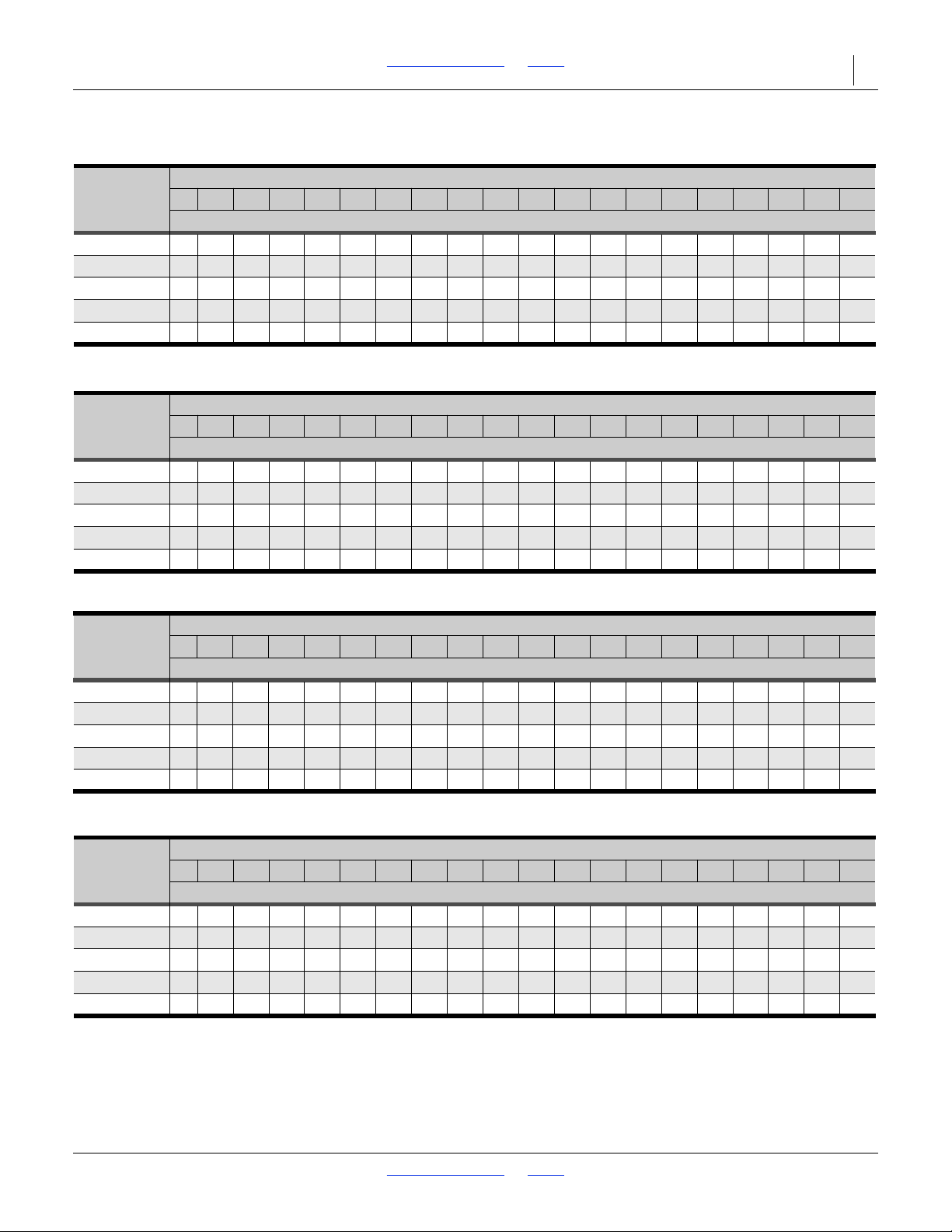
2SF24 and 2SF30 Table of Contents Index Adjustments 47
Red & Sweet Clover, Lespedeza Hulled
Rate Adjuster Setting
Row 5 10 15 20 25 30 35404550556065707580 859095100
Spacing
Seed Rate in Pounds per Acre
6 inch 0 1.5 3.4 5.2 7.1 9.0 11.3 13.2 15.3 17.0 19.0 21 23 25 26 2830 32 34 36
7 inch 0 1.3 2.9 4.5 6.1 7.7 9.7 11.3 13.1 14.6 16.3 17.8 19.3 21 23 25 26 28 29 31
7.5 inch 0 1.2 2.7 4.2 5.7 7.2 9.1 10.6 12.3 13.7 15.3 16.7 18.1 19.7 21 23 24 26 27 29
8 inch 0 1.1 2.5 3.9 5.3 6.7 8.5 9.9 11.5 12.8 14.3 15.6 16.9 18.3 19.8 21 23
24 25 27
10 inch 0 0.9 2.0 3.1 4.2 5.3 6.7 7.8 9.0 10.0 11.2 12.2 13.3 14.4 15.6 16.6 17.8 18.9 19.9 21
Kentucky Blue Grass, Fescue, Annual Rye Grass
Rate Adjuster Setting
Row 5 10 15 20 25 30 35404550556065707580 859095100
Spacing
Seed Rate in Pounds per Acre
6 inch 0 0.2 1.2 1.9 2.7 3.3 4.1 4.6 5.2 5.8 6.3 6.8 7.3 7.88.38.8 9.2 9.7 10.0 10.5
7 inch 0 0.2 1.0 1.6 2.3 2.83.5 4.0 4.5 5.0 5.4 5.9 6.3 6.7 7.1 7.5 7.9 8.0 8.6 9.0
7.5 inch 0 0.2 0.9 1.5 2.2 2.7 3.33.7 4.2 4.6 5.1 5.5 5.9 6.3 6.7 7.0 7.4 7.7 8.1 8.4
8 inch 0 0.2 0.9 1.4 2.0 2.5 3.0 3 .5 3.9 4.3 4.8 5.1 5.5 5.9 6.2 6.6 6.9 7.5 7.5 7.9
10 inch 0 0.1 0.7 1.1 1.6 2.0 2.4 2.7 3.1 3.4 3.7 4.0 4.3 4.6 4.9 5.2 5.4 5.7 5.9 6.2
Millet, Reed Canary
Rate Adjuster Setting
Row 5 10 15 20 25 30 35404550556065707580 859095100
Spacing
Seed Rate in Pounds per Acre
6 inch 0.4 1.4 2.4 3.5 4.4 5.5 6.5 7.5 8.5 9.5 10.5 11.5 12.5 13.6 14.6 15.6 16.6 17.6 18.5 19.0
7 inch 0.4 1.2 2.1 3.0 3.8 4.7 5.6 6.4 7.38.1 9.0 9.9 10.7 11.6 12.5 13.3 14.2 15.1 15.9 16.1
7.5 inch 0.3 1.2 2.0 2.83.6 4.4 5.2 6.0 6.8 7.6 8.4 9.3 10.1 10.9 11.7 12.5 13.3 14.1 14.9 15.1
8 inch 0.3 1.1 1.8 2.6 3.3 4.1 4.9 5.6 6.4 7.1 7.9 8.6 9.4 10.2 10.9 11.7 12.4 13.2 13.9 14.1
10 inch 0.3 0.8 1.4 2.0 2.6 3.2 3.8 4.4 5.0 5.6 6.2 6.8 7.4 8.0 8.6 9.2 9.8 10.4 10.9 11.5
Orchard Grass
Rate Adjuster Setting
Row 5 10 15 20 25 30 35404550556065707580 859095100
Spacing
Seed Rate in Pounds per Acre
6 inch 0 0 0.3 0.7 0.9 1.3 1.5 2.0 2.4 2.83.33.5 3.9 4.4 4.8 5.0 5.5 5.7 6.1 6.3
7 inch 0 0 0.2 0.6 0.7 1.1 1.3 1.7 2.1 2.4 2.83.0 3.4 3.7 4.1 4.3 4.7 5.0 5.2 5.4
7.5 inch 0 0 0.2 0.5 0.7 1.1 1.2 1.6 1.9 2.3 2.6 2.83.2 3.5 3.9 4.0 4.4 4.6 4.9 5.1
8 inch 0 0 0.2 0.5 0.7 1.0 1.1 1.5 1.8 2.1 2.5 2.6 2.9 3.33.6 3.8 4.1 4.3 4.6 4.8
10 inch 0 0 0.1 0.4 0.5 0.8 0.9 1.2 1.4 1.7 1.9 2.1 2.3 2.6 2.83.0 3.2 3.33.6 3.7
2018-08-02 Table of Contents Index 155-015M-A
Page 52
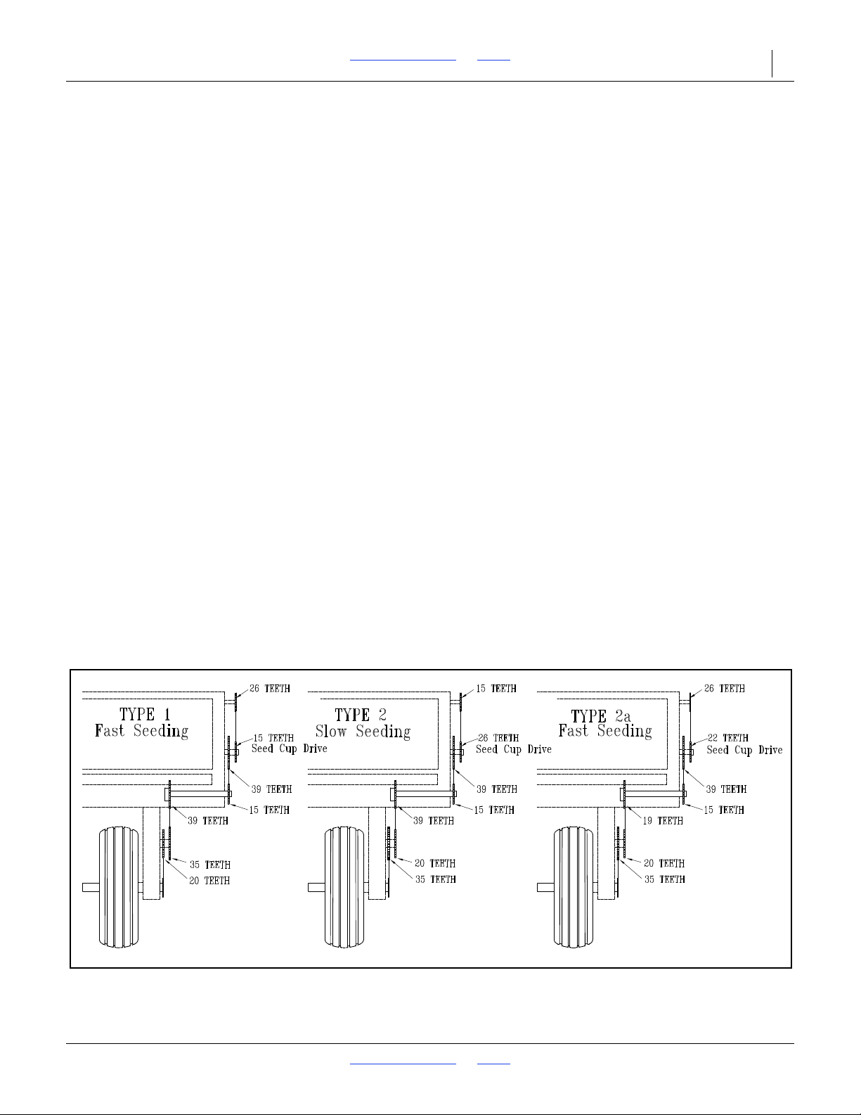
2SF24 and 2SF30 Table of Contents Index Adjustments 48
Figure 36
Sprocket Arrangements
10604
Fertilizer Meter Rate
Application rates will vary with fertilizer type, density and
particle size. Relative humidity and field conditions can
also affect application rates. The chart on the page 49 is
based on material with a density of 65 pounds per cubic
foot (1.04 kg/L) and average particle size. Initially set the
rate according to the charts, then calibrate the drill to
your material as described below.
If your drill has two boxes, remember to repeat the
following steps for each drill box.
1. Raise the drill with the tractor hydraulics so the drive
wheels are off the ground. Rotate the drive wheels to
see that the metering system is working properly and
free from foreign material.
2. From the chart, find the setting number for your row
spacing and desired application rate. Rotate the gate
adjustment knob to the number obtained from the
chart.
3. Check that your gauge-wheel tires are the correct
size 9.5L x 15 inches and properly inflated. See “Tire
Inflation Chart” on page 68.
4. Record the weight of an empty container large
enough to hold the fertilizer metered for one acre.
5. Place several pounds of fertilizer over three fertilizer
feed cups on the outside end of the drill box. Pull the
fertilizer tubes off of these three openers.
6. Turn the gauge wheels a few turns to fill the feed
cups with material. Continue to turn until fertilizer
drops to the ground from all three tubes.
7. Place a container under the three tubes to gather
metered fertilizer.
8. Turn the gauge wheel until for one acre
(approximately 225 tire rotations on a 24-foot drill
and 182 rotations on a 30-foot drill). Check that the
three feed cups have plenty of fertilizer coming into
them.
9. Weigh the metered material. Subtract the initial
weight of the empty container. Divide by three.
Multiply by the number of openers on your drill to
determine total pounds-per-acre metered. If this
figure is different than desired, reset adjustment
knob accordingly.
NOTE:
You may want to repeat the calibration procedure if
your results vary greatly from the chart.
When drilling, check the rate by noting acres drilled,
amount of fertilizer added to drill and level of material in
drill box. If you are applying more or less than desired,
adjust the metering rate slightly to compensate for field
conditions.
Seeding Drive Speeds
Refer to Figure 36
When changing seeding drive speed for faster or slower
seeding, the fertilizer drive sprocket must also be
changed in order for the fertilizer rotor to maintain
consistent speed. The drawings below illustrate the
proper sprocket arrangement when using different types
of seeding drive speeds.
2018-08-02 Table of Contents Index 155-015M-A
Page 53
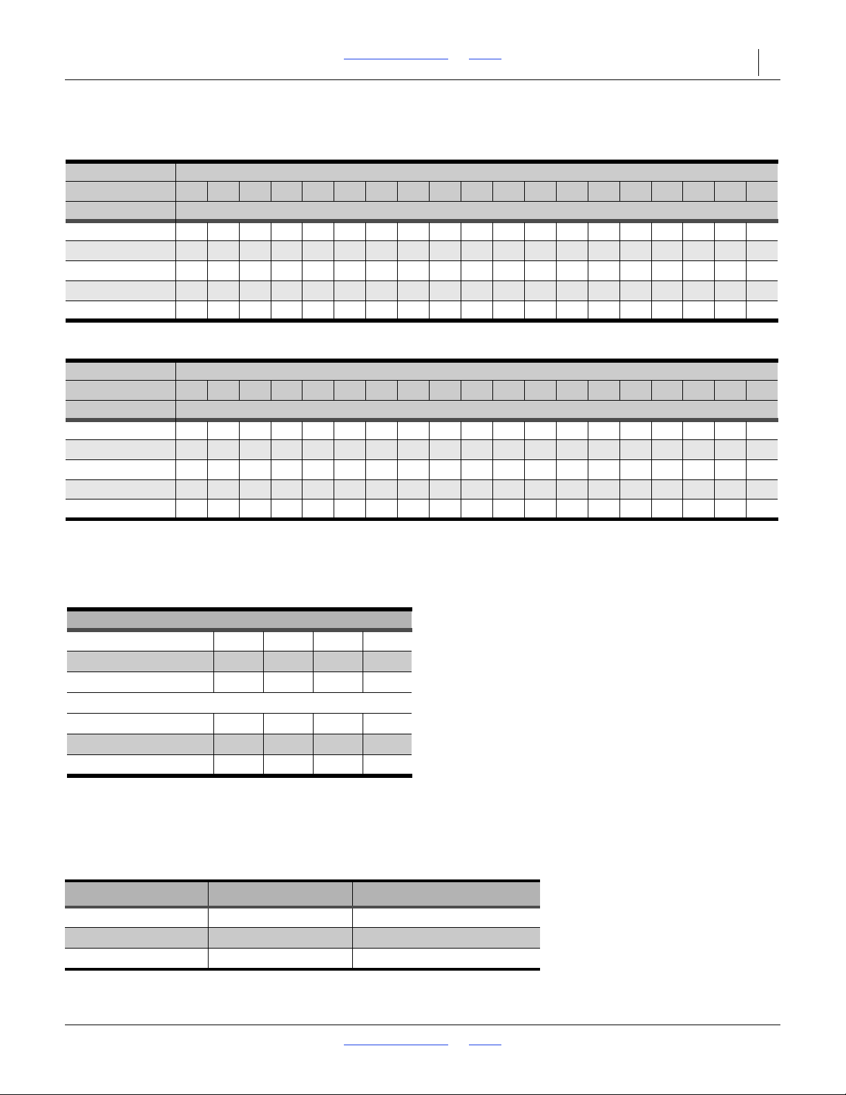
2SF24 and 2SF30 Table of Contents Index Adjustments 49
Fertilizer
Rate Adjuster Setting
2014+ 1015202530 35404550556065707580 859095100
Row Spacing Application Rate - Pounds per Acre*
6 inch 9 13 25 48 67 89 112 131154173 197 218 234 261 279 292 303306 308
7 inch 9 13 23 41 57 78 95 111 131148 165 184 199 221 23 5 246 256 259 261
7.5 inch 7 11 20 38 54 72 8 9 105 123 138 157 174 187 209 223 234 242 245 247
8 inch 7 11 20 3650698498 115 130146163 176 195 207 219 226 228 231
10 inch 5 8 16 29 40 54 67 79 92 104 11
8 131 140 157 167 175 182183 185
* Based on 65 pounds per cubic foot.
Fertilizer
Rate Adjuster Setting
2013- 1015202530 35404550556065707580 859095100
Row Spacing Application Rate - Pounds per Acre*
6 inch 15 233148 64 87 109 125 140 168 195 210 225 248 270 295 320 345 369
7 inch 13 20 26 38 54 74 93 106 119 143 166 179 191 211 230 251 272 293314
7.5 inch 12 18 24 37516887 100 112 134156168 180198 216 236 256 276 295
8 inch 11 17 233648 62 82 94 105 126 146 158 169 186203 221 240 259 277
10 inch 9 14 19 29 38 52 66 75 84 101 117 126 135 149 162 177 192 207 221
* Based on 65 pounds per cubic foot.
Dry Fertilizer Density Adjustment
Pounds/Cubic-Foot
45 50 55 60
Kilograms/Liter
0.72 0.800.88 0.96
Conversion Factor
1.44 1.301.18 1.08
Pounds/Cubic-Foot
65 70 75 80
Kilograms/Liter
1.04 1.12 1.20 1.28
Conversion Factor
1.00 0.93 0.870.81
34755
Fertilizer Rate Charts U.S. Customary Units
Density Conversion Chart
The fertilizer meter rate charts are based on fertilizer with a density of 65 pounds per cubic foot (1.04 kilograms per
liter). If you are applying fertilizer of a different density, use the following table to convert application rate.
Example: Your fertilizer has a density of 75 pounds per cubic foot, and you want to apply 100 pounds per acre. Multiply
the desired application rate by the conversion factor: 100 x 0.87 = 87
Adjust drill to the setting closest to 87 pounds per acre.
Fertilizer Sprockets
Drill Drive Type Fertilizer Sprocket (3) Feeder Cup Sprocket (4)
Drive Type 1 26T 15T
Drive Type 2 15T 26T
DriveType2A 26T 22T
2018-08-02 Table of Contents Index 155-015M-A
Page 54

2SF24 and 2SF30 Table of Contents Index Adjustments 50
Figure 37
Speed Adjustment, Dual Markers
14048
1
2
Figure 38
Single Marker Speed Adjustment
15625
Marker Adjustments
Folding Speed
Refer to Figure 37
Adjust folding speed for dual markers with hex
adjustment screws on the sequence-valve body. There is
one adjustment screw for raising (fold) speed (1) and one
for lowering (extend) speed (2). You can identify
adjustment screws by markings stamped in valve body.
Turn adjustment screws clockwise to decrease folding
speed and counterclockwise to increase folding speed.
With tractor idling at a normal operating speed, adjust
marker folding to a safe speed. Excessive folding speed
could damage markers and void the warranty.
After adjusting the folding speed, tighten jam nuts on hex
adjustment screws to hold settings.
Refer to Figure 38
The hydraulic system for a single marker has a needle
valve to control folding speed. The needle valve is in the
hydraulic hose at rod end of marker cylinder.
Turn adjustment knob clockwise to reduce folding speed
or counterclockwise to increase folding speed. With
tractor idling at a normal operating speed, adjust marker
folding to a safe speed. Excessive folding speed could
damage markers and void the warranty.
2018-08-02 Table of Contents Index 155-015M-A
Page 55
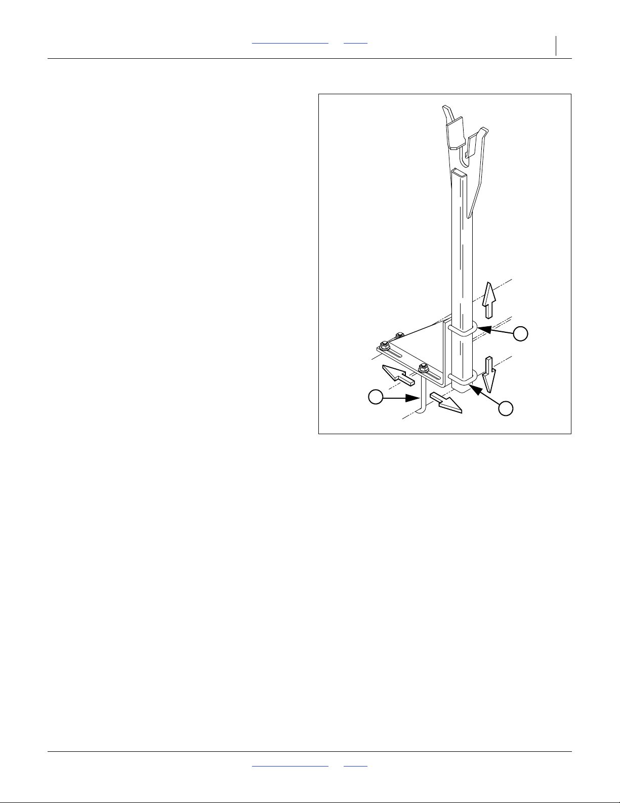
2SF24 and 2SF30 Table of Contents Index Adjustments 51
Figure 39
Marker Transport Carrier
Adjustment
15632
2
1
2
Transport Carrier
Refer to Figure 39
When marker is folded, the second section should be
centered in transport-carrier saddle and parallel with top
of drill box.
To adjust front-to-rear position of saddle, loosen
1
/2x 6 inch U-bolts (1) that fasten transport-carrier
mount onto box frame. Slide transport-carrier assembly
forward or back as needed.
1
To adjust height of saddle, loosen
that hold carrier tube to mounting bracket. Slide carrier
tube up or down as needed.
/2x 2 inch U-bolts (2)
2018-08-02 Table of Contents Index 155-015M-A
Page 56
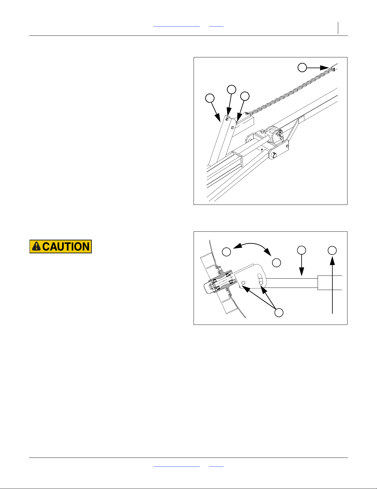
2SF24 and 2SF30 Table of Contents Index Adjustments 52
Figure 40
Marker Chain Adjustment
15669
1
3
4
2
Figure 41
Marker Disk Angle
11757
N
W
2
1
T
Marker Chain
Refer to Figure 40
There are two, interrelated adjustments for the marker
chain. Make these adjustments in the following order.
Lifting Slack. With marker unfolded, back full-threaded
adjustment bolt (1) down until head extends as little as
possible. Slowly fold marker while observing disk. If
marker disk slides across ground more than a foot before
chain and linkage lifts it up, the chain is too long.
Shorten chain one or two links by moving clevis (2).
Check adjustment by repeating folding process.
If chain is too short when marker is unfolded, it will
prevent end of marker from dropping into field
depressions, causing skips in your marker line. Correct
this condition by lengthening chain one or two links at
clevis (2).
Folding Slack. Fold marker. Use full-threaded
adjustment bolt (1) to take slack out of chain while
marker is folded. Extend bolt until there is no chain slack.
Lock bolt in this position by tightening nuts (3) on either
side of upright channel (4).
Marker Disk Adjustment
Sharp Object Hazard:
Use caution when making adjustments in this area. Marker
disks may be sharp.
Refer to Figure 41
There are two ways you can change the mark left by the
marker disk.
Disk Angle
1. To change angle of cut, and the width of the mark,
loosen
For a wider mark (W), increase the angle of the
marker with respect to the tube (1). For a narrower
mark (N), reduce the angle.
NOTE:
Do not set a marker angle wider than need to make a
useful mark. Excess angle increases wear on all
marker components.
2. Tighten bolts (2).
Direction of Cut
To change direction of cut and throw dirt either in or out:
Reverse blade and depth band by remounting lug bolts
on disk hub.
1
/2inch bolts (2) holding the disk assembly.
2018-08-02 Table of Contents Index 155-015M-A
Page 57
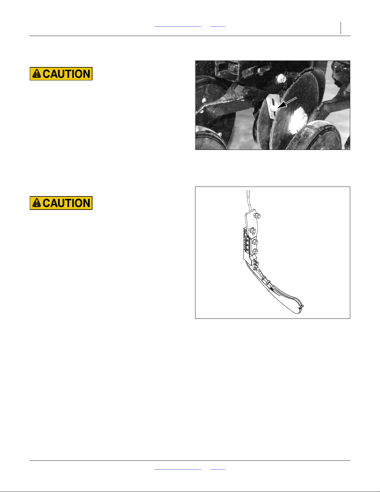
2SF24 and 2SF30 Table of Contents Index Adjustments 53
Figure 42
Opener Disk Scraper
26463
Figure 43
Keeton
®
Seed Firmer
26443
Disk Scraper Adjustments
Sharp Object Hazard:
Row unit disk blades may be sharp. Use caution when making
adjustments in this area.
Refer to Figure 42
Disk scrapers are optional. To keep opener disks turning
freely, dirt scrapers are mounted between disks to clean
as disks rotate.
As field conditions vary, scrapers may need to be
adjusted. In damp conditions, lower scrapers. If openers
are not turning freely, raise scrapers. To adjust, loosen
bolt and move scraper as needed.
Seed Firmer Adjustments
Sharp Object Hazard:
Row unit disk blades may be sharp. Use caution when making
adjustments in this area. To adjust the Keeton
lower the drill until the disks of the row units are resting on the
ground.
®
Seed Firmer,
Keeton® Seed Firmer Adjustment
The optional Keeton® Seed Firmer is an engineered
polymer shape that slides down the seed trench. It traps
seeds as they exit the seed tube and firms them into the
bottom of the "V".
Refer to Figure 43
The Firmer is provided with a preset tension which is
recommended for using the first year. The tension screw
can be tightened in subsequent years according to your
needs. Firmers should provide just enough tension to
push seeds to the bottom of the trench.
2018-08-02 Table of Contents Index 155-015M-A
Page 58
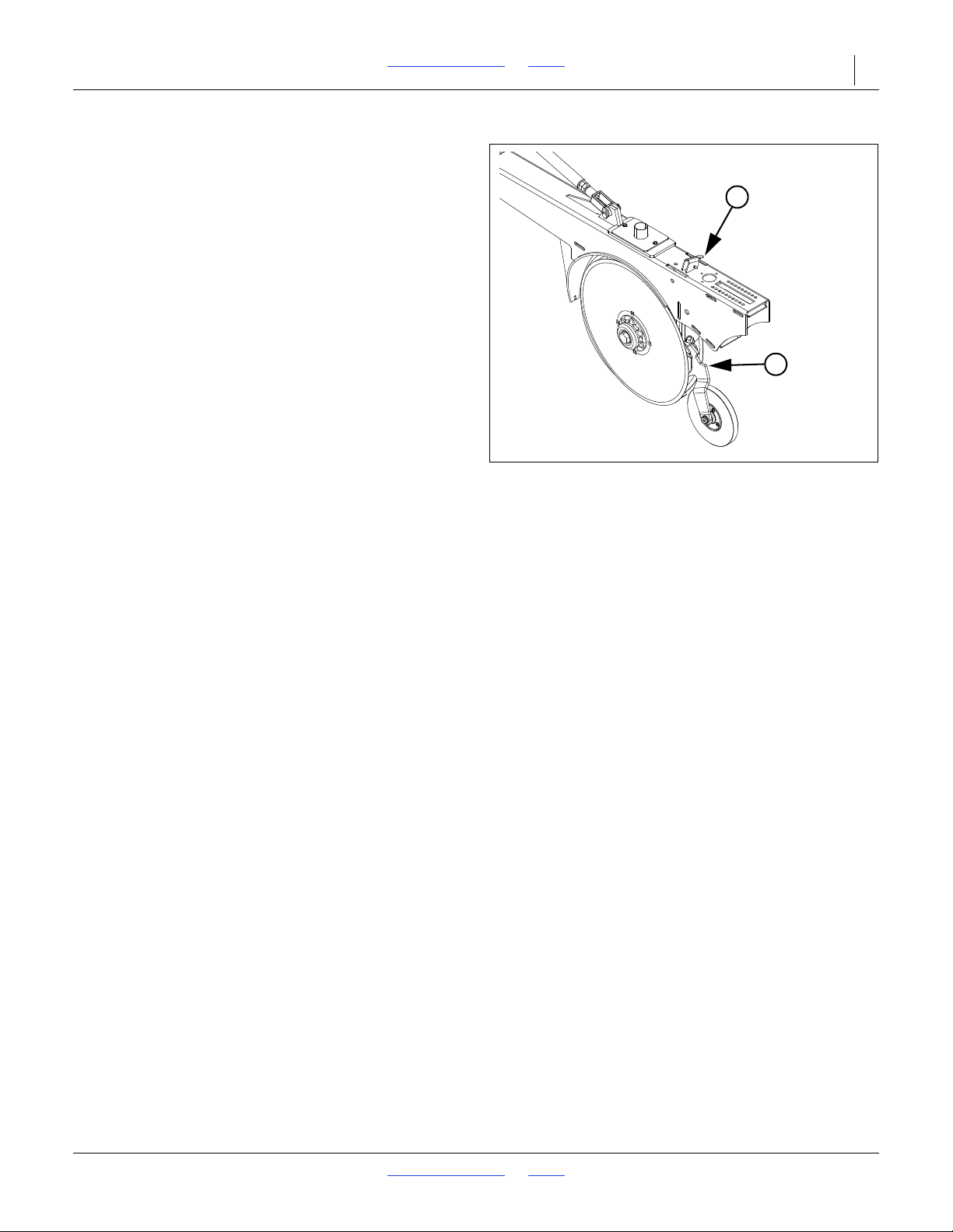
2SF24 and 2SF30 Table of Contents Index Adjustments 54
Figure 44
Seed-Lok
®
Lock-Up
26443
1
2
Seed-Lok® Seed Firmer Lock-Up
Refer to Figure 44
Optional Seed-Lok
seed-to-soil contact. The wheels are spring loaded and
do not require adjusting. In some wet and sticky
conditions the wheels may accumulate soil. To avoid
problems associated with this, you can lock-up the
firmers.
To lock up Seed-Lok
• Pull up on Seed-Lok
®
firming wheels provide additional
®
wheels:
®
arm (1).
• Raise lever (2).
2018-08-02 Table of Contents Index 155-015M-A
Page 59
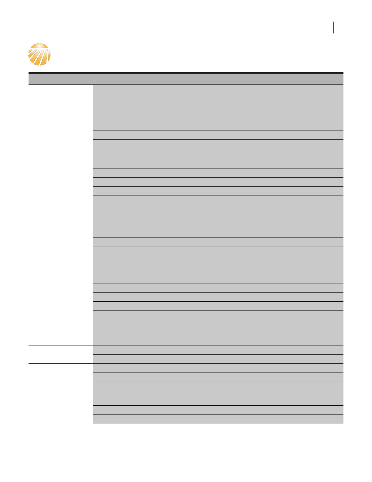
2SF24 and 2SF30 Table of Contents Index 55
Troubleshooting
Problem Solution
Uneven Seed
Spacing or Uneven
Stand
Opener Disks Not
Turning Freely
Actual Seeding Rate
Is Different than
Desired
Excessive Seed
Cracking
Acremeter Does Not
Measure Accurately
Uneven Seeding
Depth
Press Wheels Not
Compacting Soil As
Desired
Grain Box Not
Emptying Evenly
Check for plugging in seed cup.
Check to see if seed tubes are plugged.
Reduce ground speed.
Check opener disks to see they turn freely.
Use faster drive speed and close seed cup flutes to a more narrow position.
Spring pressure on openers could be improperly adjusted causing opener to not penetrate low spots.
Check for trash or mud build-up on Seed-Lok® wheel.
Check for trash or mud build-up on disk scraper. Re-adjust scraper.
Check to see if scraper is adjusted too tightly and is restricting disk movement.
Check disk bearings.
Check opener frame for possible damage.
If opener disks turn freely by hand but not in field, reduce down pressure on disk opener.
Check press wheel adjustment for seeding depth.
Check tire pressure. For proper inflation see “Tire Inflation Chart” on page 68.
Check gauge wheel size. Proper size is 9.5L x 15.
Seed treatment will affect seeding rate if the chemicals build up in seed cup. Unless cleaned regularly,
this build up can cause breakage of the seed-cup shaft.
Check speed change box setting.
For instructions on calculating seed rate see “Seeding Adjustments” on page 37.
Use slower drive speed and open flutes in seed cup to a wider position.
Position seed-cup handles to a lower notch.
Check tire pressure. For proper inflation see “Tire Inflation Chart” on page 68.
Check end gauge wheel tire size. proper size is 9.5L x 15.
Check planting operation for excessive overlap or gaps between passes.
Loose soil conditions and slippage will cause variations in acres registered.
To check accuracy of acremeter, see “The acremeter counts shaft rotations whenever the shaft is
rotating - this is with the drill lowered and in motion or during calibration crank operation. The
meter is programmed to display rotations as acres or hectares, when using all rows,
factory-specified tires and tire inflations.” on page 32.
Check to be sure your acremeter is for your width of drill.
See “Planting Depth Adjustments” on page 36.
See “Hitching Tractor to Drill” on page 14 and “Leveling Drill” on page 20.
Refer to “Planting Depth Adjustments” on page 36.
Re-adjust press wheel depth to match coulter depth.
Increase down pressure on disk openers.
Certain models do not have the same number of seed cups between each divider of bulkhead. The
section with the larger number of cups will empty sooner.
Seed cups close to the ends of box tend to empty sooner due to amount of seed available.
Check adjustment levers on each box to see that they are set on the same indicator number.
2018-08-02 Table of Contents Index 155-015M-A
Page 60
2SF24 and 2SF30 Table of Contents Index Troubleshooting 56
Problem Solution
Press Wheel or
Openers Plugging
Rubber Tire Depth
Drilling in damp or wet conditions may increase this problem.
Openers may be moved from a staggered to an in-line position to reduce trash thrown from front
openers into rear openers.
Reduce down pressure on openers.
Do not back up drill in the field, or stop and allow drill to roll backwards with openers in the ground.
If using double “V” press wheels, adjust angle bar.
Check Seed-Lok® wheel.
Install scrapers.
Control Wheels
Becoming Packed
With Mud
Reduce spring tension on openers.
Improper Folding of
Drills
Hydraulic Adaptors
Cracking
Seed Cup Sprockets
Locked up or
Twisted Seed-Drive
Shaft
Raising and Lowering
Drill is Rough and
Uneven
Hydraulic Marker
Functioning
Improperly
Chain-Debris/Retainer
Clip
Adjust post frame adjusting links.
Check hydraulic system for air and oil leaks.
Clean out small orifice fittings in wing cylinders.
Make sure that the wing boxes unfold to a straight line. check to see that both pull bars are attached to
the boxes at exactly the same distance inboard from the inboard edge of the drill box (90”) and both are
exactly the same length.
JIC fittings do not require high torque.
ALWAYS use liquid pipe sealant when adding or replacing pipe thread hydraulic fittings. Plastic sealant
tape can crack fittings and plug hydraulic lines. JIC and O-Ring fittings DO NOT require sealant. O-ring
fittings require a thin coat of oil on the O-Ring.
IMPORTANT: When using sealant on pipe threads, the friction between the threads is reduced,
therefore, be certain not to overtighten causing damage to the cylinders, valves or fittings.
Check for foreign matter lodged in one or more seed cup sprockets.
Liquid insecticide from seed has dried within the seed cup. Remove the build up by disassembling each
seed cup and scrape the foreign substance from the turning surfaces. NOTE: Liquid inoculant should
be applied with caution and care should be taken to clean the seeding system after drilling treated
seeds.
Lubricate lower rollers of vertical transport tubes located between the transport tires.
Check hydraulic fittings for leaks.
Rephasing cylinders not properly bled. See “Hydraulic Hose Hookup” on page 16. When raising drill
at end of field, the lifting cylinders should be fully extended to ensure that they are always rephased. If
machine is only raised enough to lift openers out of the ground, lift cylinders may eventually get out of
sequence and cause uneven seeding depth.
Check all hose fittings and connections for air and oil leaks.
The chain on the folding 3-section marker should be slack when the marker is both fully extended and
fully raised.
Check tractor hydraulic oil level.
Check all bolts and fasteners.
Double selector valve positioned for wing fold. Shift valve to marker sequence position.
Open needle valve, cycle markers slowly and reset needle valve if plugged.
Be sure retainer clip open end is facing opposite way of chain travel.
2018-08-02 Table of Contents Index 155-015M-A
Page 61
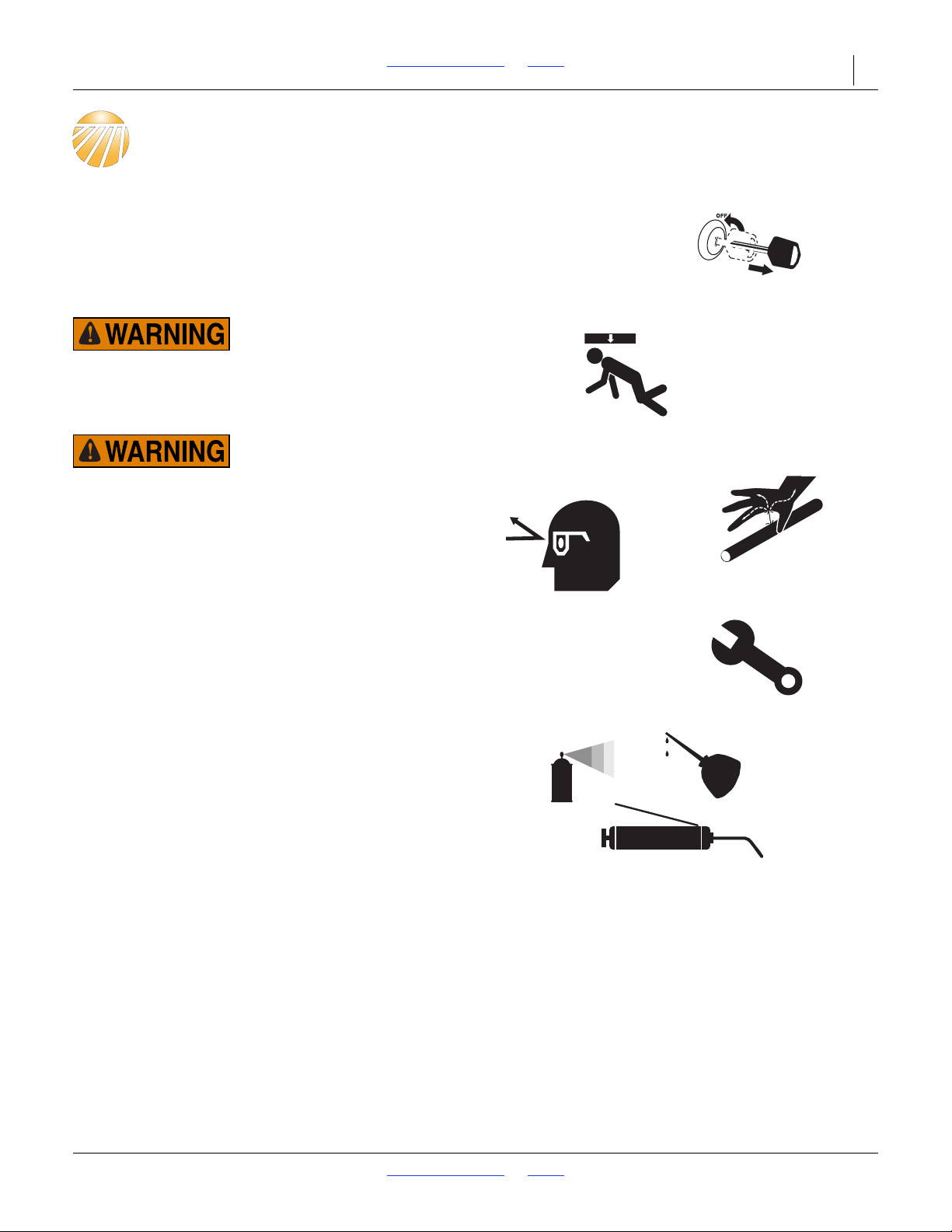
2SF24 and 2SF30 Table of Contents Index 57
Maintenance and Lubrication
Maintenance
Proper servicing and maintenance is the key to long
implement life. With careful and systematic inspection,
you can avoid costly maintenance, downtime, and repair.
Always turn off and remove the tractor key before making
any adjustments or performing any maintenance.
Crushing Hazard:
Always have transport locks in place when working on
implement. You may be severely injured or killed by being
crushed under a falling implement.
High Pressure Fluid Hazard:
Check all hydraulic lines and fittings before applying pressure.
Fluid escaping from a very small hole can be almost invisible.
Use paper or cardboard, not body parts, and wear heavy
gloves to check for suspected leaks. Escaping fluid under
pressure can have sufficient pressure to penetrate the skin. If
an accident occurs, seek immediate medical assistance from a
physician familiar with this type of injury.
1. After using your drill for several hours, check all bolts
to be sure they are tight.
2. Remove excess slack from chains. Clean and use
chain lube on all roller chains as needed.
3. Maintain proper air pressure in drill tires.
4. Check the hitch safety chain before the drill is
transported and regularly during normal operation.
Inspect the chain and hardware for wear and other
damage. Replace immediately if needed.
5. Keep disk scrapers properly adjusted.
6. Clean drill on a regular basis. Regular and thorough
cleaning will lengthen equipment life and reduce
maintenance and repair.
7. Lubricate areas listed under “Lubrication and
Scheduled Maintenance” on page 60.
8. Replace any worn, damaged, or illegible safety
labels by obtaining new labels from your Great
Plains dealer.
2018-08-02 Table of Contents Index 155-015M-A
Page 62
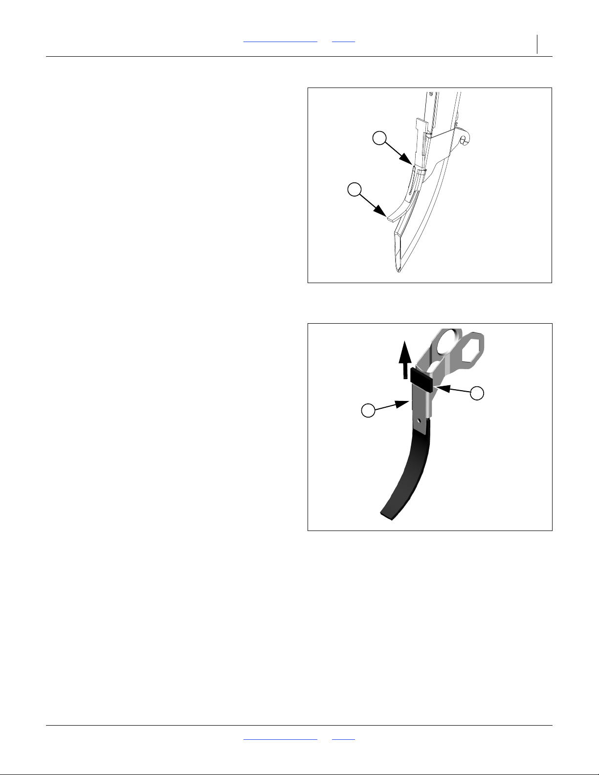
2SF24 and 2SF30 Table of Contents Index Maintenance and Lubrication 58
Figure 45
816-302C Seed Tube Flap
31047
2
1
Figure 46
817-349C Seed Tube Flap
18398
2
1
Seed Flap Replacement
Refer to Figure 45
To replace a seed flap (1), use a needle nose pliers or
similar tool to grasp “T” top of flap. Pull upward to pull
flap up out of metal bracket (2).
Push new seed flap (1) down through metal bracket (2)
until flap snaps into place with “T” top resting on top of
bracket.
Older Style Seed Flap
Refer to Figure 46
1. Remove one disk for easier seed flap replacement.
2. To replace, pull the seed flap (1) up out of metal
bracket (2).
3. Push new seed flap (1) down through metal bracket
until seed flap is in place.
2018-08-02 Table of Contents Index 155-015M-A
Page 63
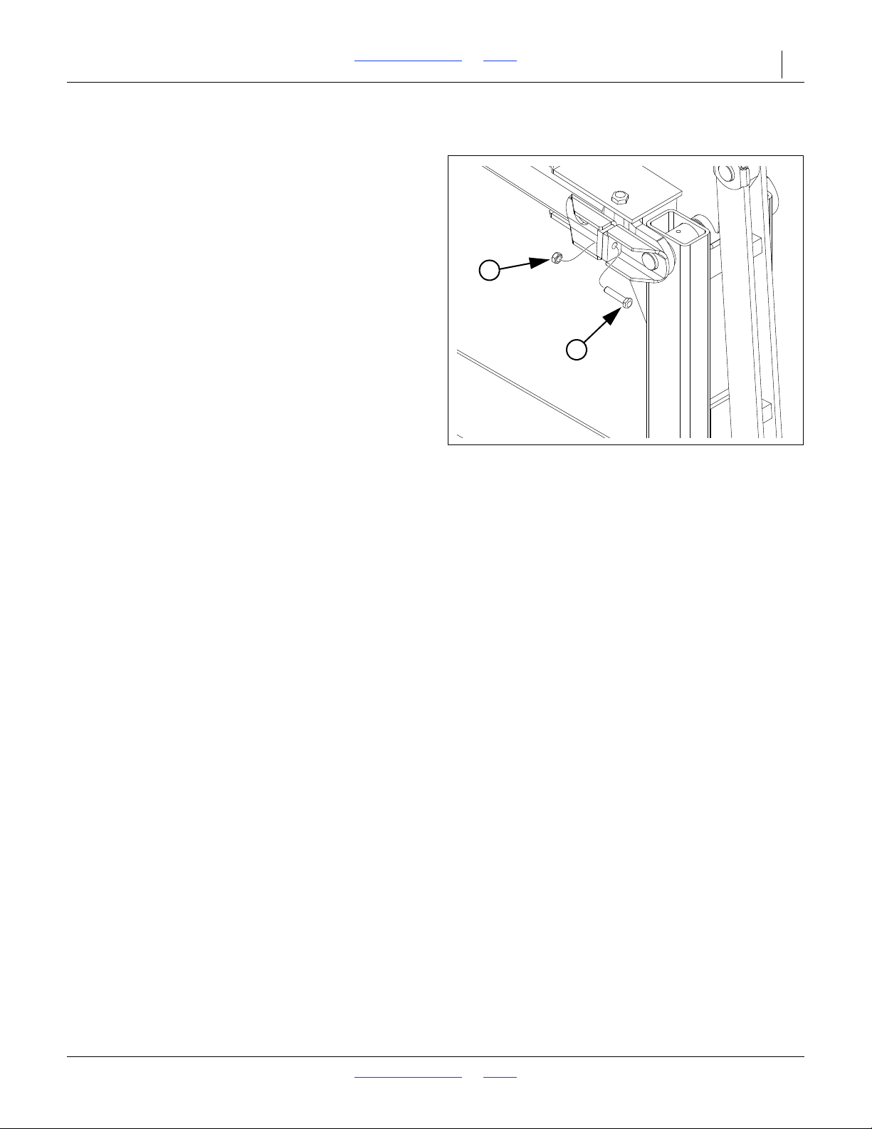
2SF24 and 2SF30 Table of Contents Index Maintenance and Lubrication 59
3
4
Figure 47
Marker Shear Bolt
34718
Marker Maintenance
Marker Shear Bolt Replacement
Refer to Figure 47
If a marker gets caught or hits an obstruction, it is
designed to fail a shear bolt (3) at the fold, pivot on a
second bolt (not visible in Figure), and swing back.
The shear bolt is a hex head cap screw,
5
(3)
/16-18 x 11/2inch Grade 5,
Great Plains part number 802-012C, plus a
5
/16-18 lock nut, Great Plains part number 803-011C.
(4)
NOTE:
If an exact replacement is not immediately available,
temporarily substitute an M8x1.25 Class 8.8 bolt and
nut.
Install a replacement shear bolt on the vertical face on
the side opposite from the pivot bolt. Do not use a higher
grade bolt, or marker hang-ups may result in machine
damage. Do not use a lower grade bolt, or you may
experience nuisance shears.
Marker Grease Seal Cap
If grease seal cap for marker-disk-hub bearings is
damaged or missing, disassemble and clean hub.
Repack with grease and install new seal or grease cap.
2018-08-02 Table of Contents Index 155-015M-A
Page 64
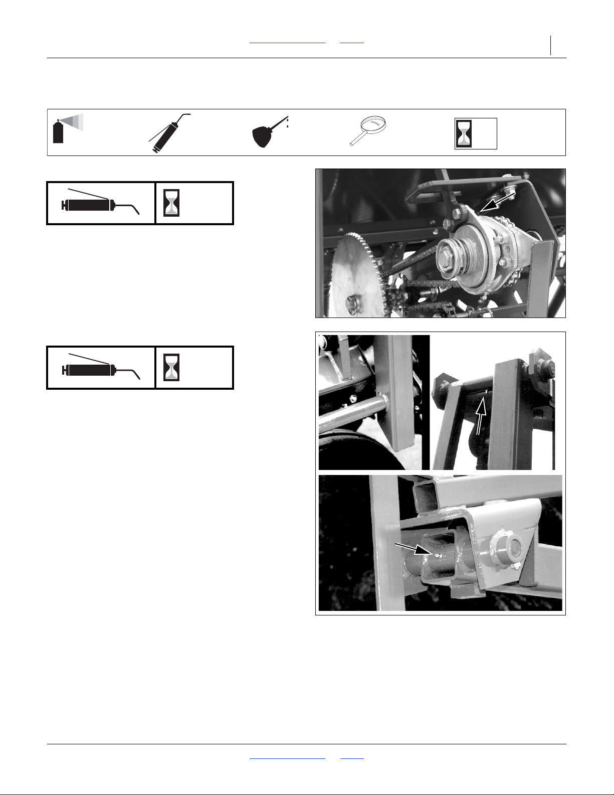
2SF24 and 2SF30 Table of Contents Index Maintenance and Lubrication 60
50
Multi-purpose
spray lubricant
Multi-purpose
grease lubricant
Multi-purpose
oil lubricant
Intervals
(operating hours)
at which service
is required
Inspection
34208
18856
15546
15547
Lubrication and Scheduled Maintenance
Drive Shaft Clutches
10
2 grease fittings each of 2 clutches; 4 total
Type of Lubrication: Grease
Quantity: Until grease emerges
Also smear grease on clutch engagement.
Marker Hinge Pivots
10
1 grease fitting at mount pivot,
1 grease fitting and 1st to 2nd section pivot,
1 grease fitting at 2nd section to arm pivot;
3 or 6 total
Type of Lubrication: Grease
Quantity: Until grease emerges at pivot ends
2018-08-02 Table of Contents Index 155-015M-A
Page 65
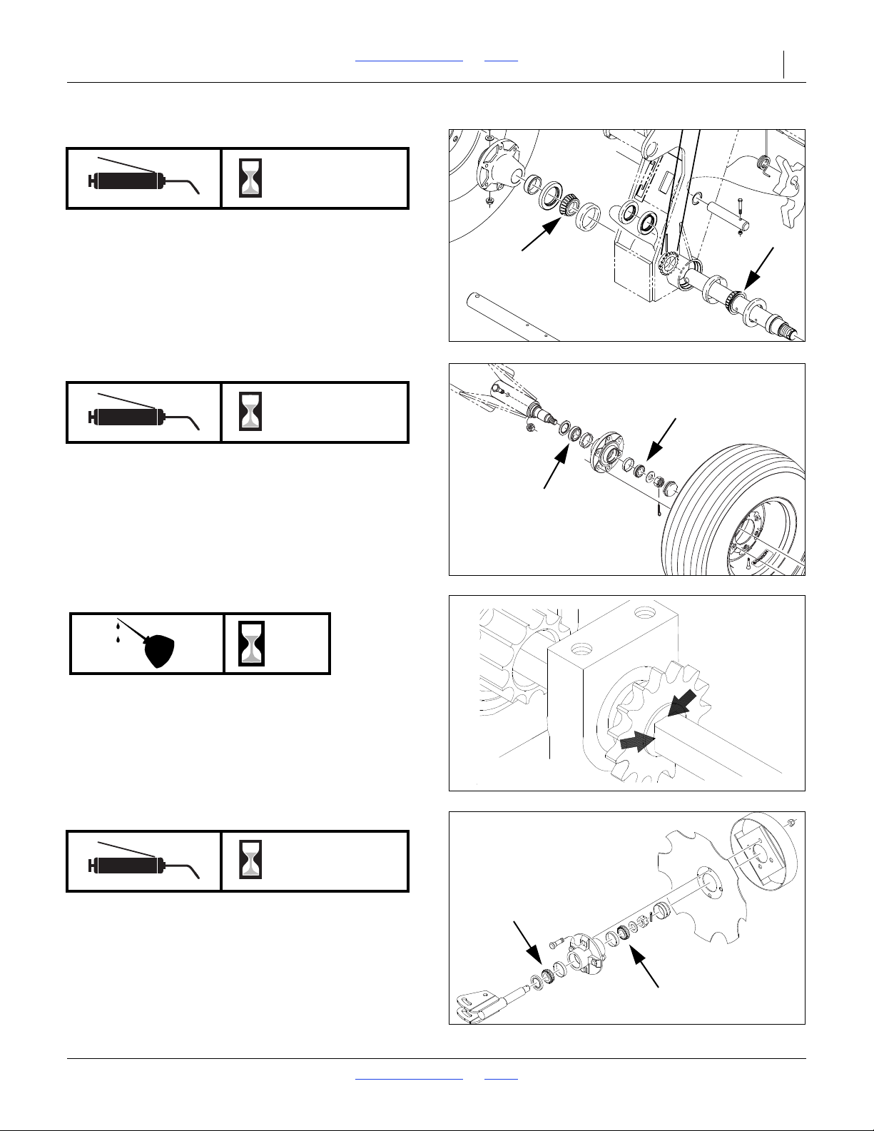
2SF24 and 2SF30 Table of Contents Index Maintenance and Lubrication 61
15457
18856
12126
50
18856
Gauge Wheel Bearings
Seasonal
2 races each of 4 wheels; 8 total
Type of Lubrication: Grease
Quantity: Repack
Transport Wheel Bearings
Seasonal
2 races each of 4 wheels; 8 total
Type of Lubrication: Grease
Quantity: Repack
Seed Cup Drive Shaft Sprocket
2 sliding sprockets; one each side
Type of Lubrication: Oil
Quantity: Coat thoroughly
Move the Seed Rate adjustment handle back and forth to
get oil into the square bore. Perform this with seed box
empty, or handle may be difficult to set to 100.
Marker Disk Bearings
Seasonal
2 races each marker; 2 or 4 total
Type of Lubrication: Grease
Quantity: Repack
2018-08-02 Table of Contents Index 155-015M-A
Page 66
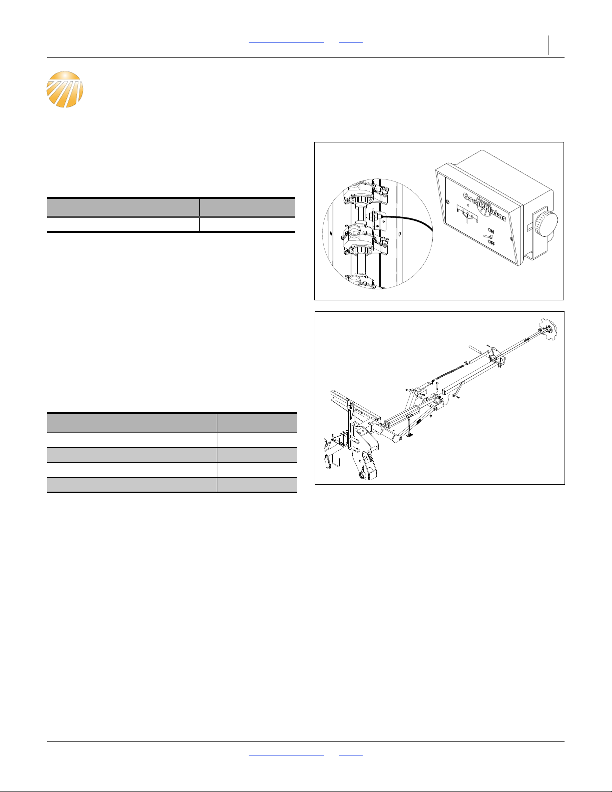
2SF24 and 2SF30 Table of Contents Index 62
34210
18943
25497
Options
Shaft Monitor
This kit provides a cab alarm in the event that a main box
seed meter shaft stops turning (which might result from
excess down-pressure lifting a gauge wheel, low tire
pressure/flat tire, chain break or clutch malfunction).
Order one kit per drill.
Description Part Number
2-Channel Shaft Monitor 116-282A
Flat Folding Markers
Hydraulically operated markers provide precise
pass-to-pass spacing by leaving a user-controlled visible
score mark to one side.
The single marker is left-side mounted. Dual markers are
operated through an automatic sequence valve. After
each fold operation, the next unfold extends the other
marker. Order one kit per drill.
Description Part Number
Single Flat Fold Marker 24 foot 113-200A
Single Flat Fold Marker 30 foot 113-196A
Dual Flat Fold Marker 24 foot 113-201A
Dual Flat Fold Marker 30 foot 113-197A
Dual gauge wheels and markers not compatible on
2SF24.
2018-08-02 Table of Contents Index 155-015M-A
Page 67
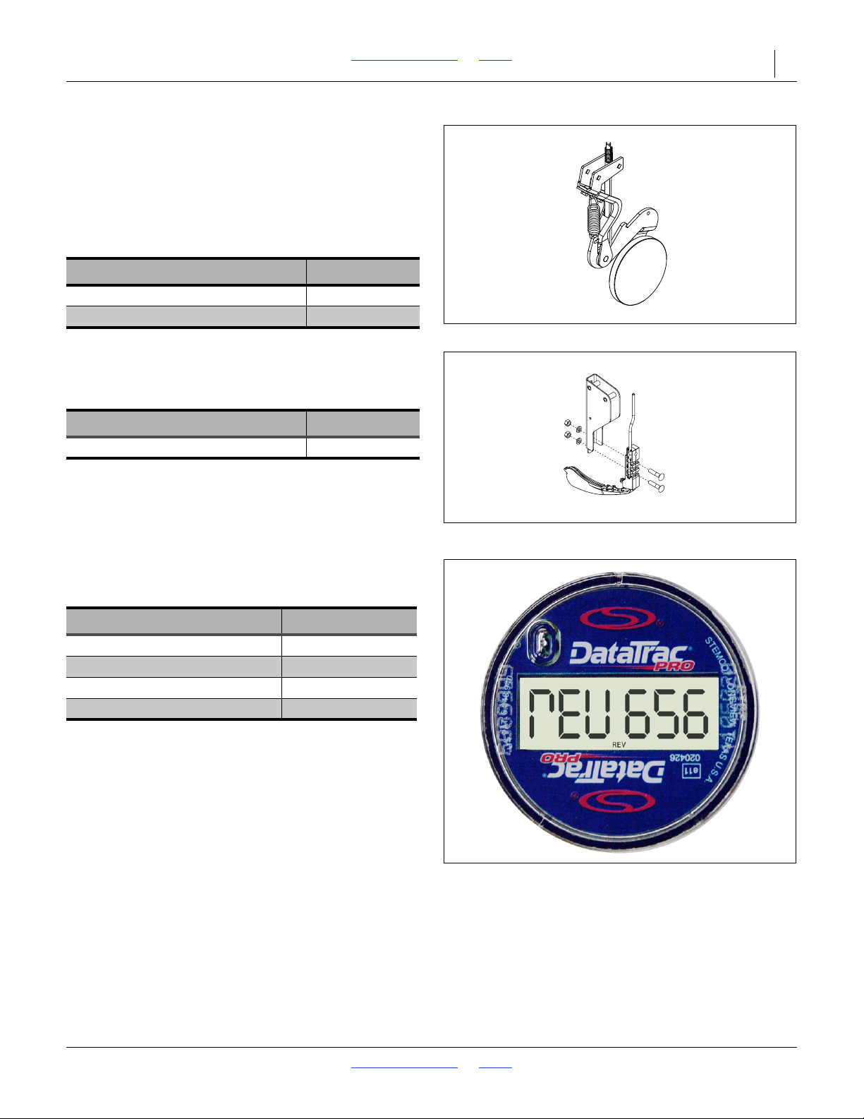
2SF24 and 2SF30 Table of Contents Index Options 63
25293
28316
Seed Firmers
The base 2SF24 and 2SF30 product requires a choice of
row unit bundles which include one of three firmers: seed
flap, Keeton
firmer may be installed at the same time. Order one per
row.
Seed-Lok
Keeton
The Keeton
delivery.
Keeton
®
, or Seed-Lok®. Only one type of seed
®
Seed Firmer
Description Part Number
00 Series 5 inch Seed-Lok
00 Series 6 inch Seed-Lok
®
Seed Firmer
®
seed firmer supports low-rate fertilizer
Description Part Number
®
seed firmer (per opener) 890-810C
®
®
122-193K
122-266K
Acremeter
Should a mechanical acremeter fail, or an electronic
acremeter’s battery life be exceeded, replace it with our
current electronic meter.
Description Part Number
24 foot Acremeter 891-107C
24 foot Hectare Meter 891-108C
30 foot Acremeter 891-041C
30 foot Hectare Meter 891-042C
2018-08-02 Table of Contents Index 155-015M-A
Page 68
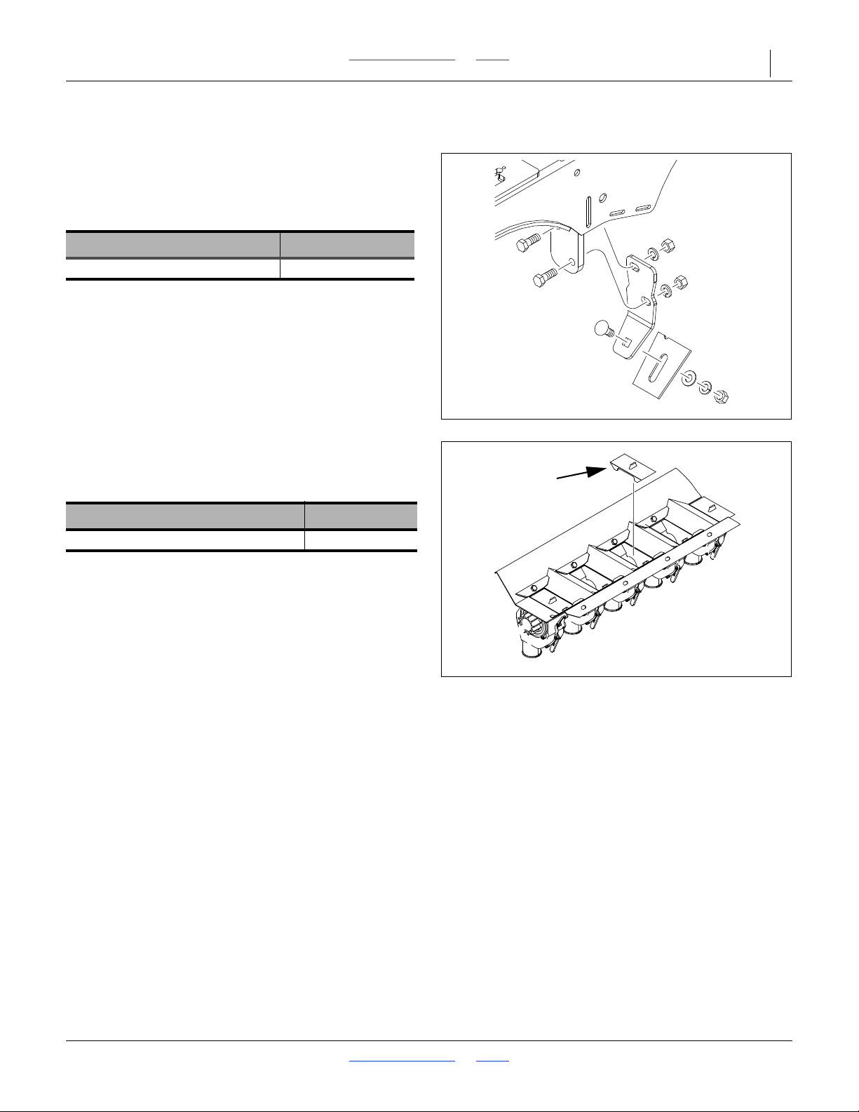
2SF24 and 2SF30 Table of Contents Index Options 64
26460
26279
Air Design Spring Loaded Scrapers
Optional disk scrapers help clear any soil and debris not
removed by the standard disk spreaders at the seed
tube. Scraper cannot be mounted if optional seed firmers
are used. Scrapers are compatible with the standard
seed flap.
Description Part Number
Spring Scraper Assembly 121-781A
Not compatible with Keeton
®
seed firmers.
Feeder Cup Plugs
This plug stops seed flow from the main seed box above
the meter. Order one per row to be set inactive.
Description Part Number
1 1/4 Wide Feeder Cup Plug 817-200C
2018-08-02 Table of Contents Index 155-015M-A
Page 69
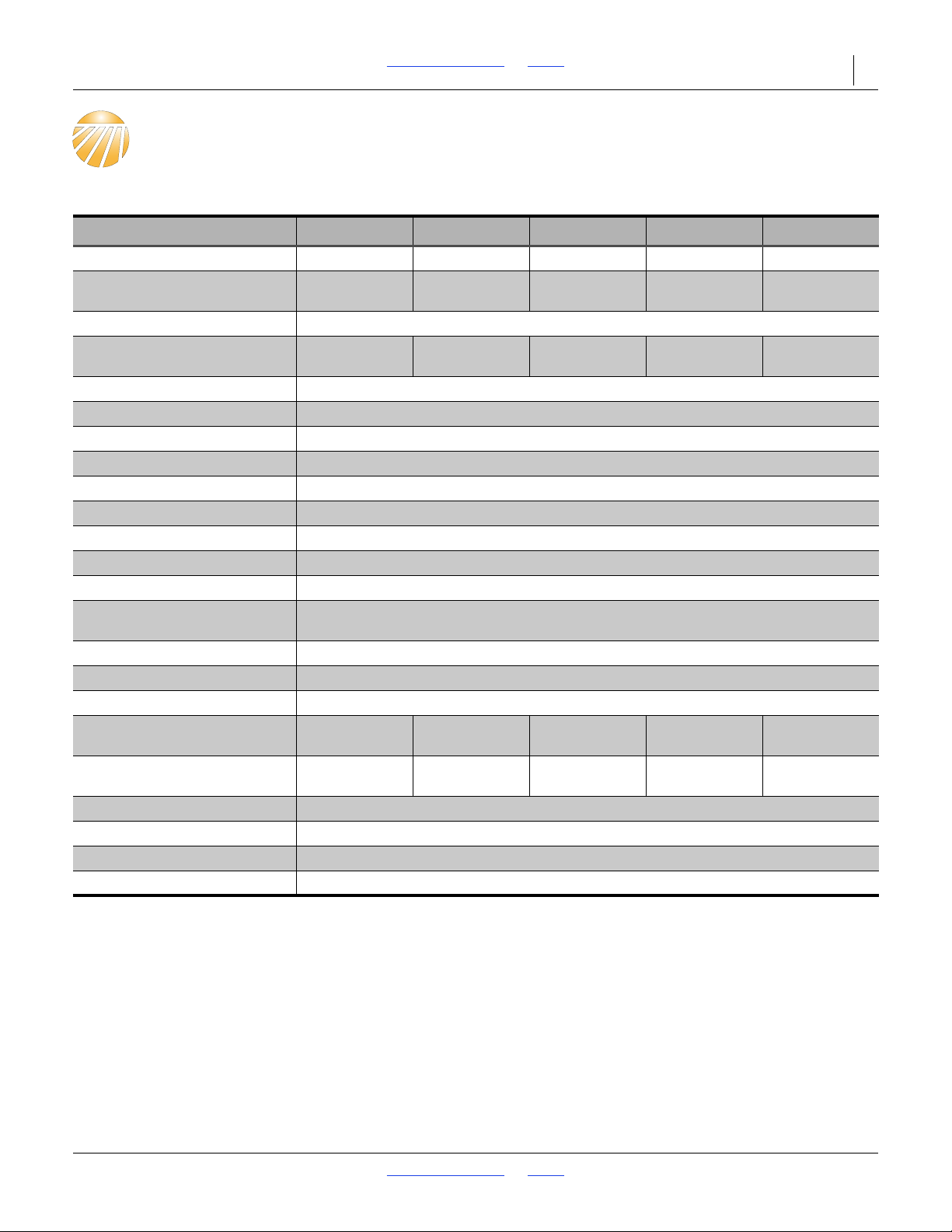
2SF24 and 2SF30 Table of Contents Index 65
Appendix A - Reference Information
Specifications and Capacities
24-Foot (7.2 m) Models 2SF24-2810 2SF24-3608 2SF24-3875 2SF24-4007 2SF24-4806
Row Count 28 36 38 40 48
Row Spacing 10 inches
(25.4 cm)
Working Width 24 feet 9 inches (7.54 m)
Swath (Channel Width) 280 inches
(711.2 cm)
Seed Capacity 48 bushel (1690 liters)
Fertilizer Capacity 24 cubic feet (800 liters)
Small Seed Capacity 6.8 bushels (240 liters)
Transport Width 14 feet (4.27 m)
Working Length 23 feet 2 inches (7.06 m)
Transport Length 19 feet 4 inches (5.89 m)
Working Height 6 feet 4 inches (1.92 m)
Transport Height 7 feet 7 inches (231 cm)
Transport Clearance 19 inches (48 cm)
Minimum Tractor
Requirement
Hitch Pull Type, Large Diameter, Small Clevis or Small Strap
Hydraulic Circuits Required Closed or Open Center, 2 or 3 Remotes
Hydraulic Power Required 2250 psi (155 bar) at 5 gallons/minute (19 liters/minute)
Weight
(minimum, empty)
Weight
(maximum, full
Transport Tire Size 9.5Lx15 12 Ply Tubeless
Wing Gauge Wheel Tire Size 9.5L-15SL 8 Ply
Opener Down Pressure 90 to 180 pounds (40 to 80 kg)
Opener Depth Range 4 inches (8.9 cm) in 1/4 inch (6.4 mm) increments
7,500 pounds
(3400 kg)
15,100 pounds
(6800 kg)
8.0 inches
(20 cm)
288 inches
(731.5 cm)
8,000 pounds
(3600 kg)
15,600 pounds
(7100 kg)
7.5 inches
(19 cm)
285 inches
(723.9 cm)
125 hp (93 kW)
8,200 pounds
(3700 kg)
15,700 pounds
(7100 kg)
7 inches
(17.8 cm)
280 inches
(711.2 cm)
8,300 pounds
(3800 kg)
15,900 pounds
(7200 kg)
6 inches
(15.2 cm)
288 inches
(731.5 cm)
8,800 pounds
(4000 kg)
16,400 pounds
(7400 kg)
2018-08-02 Table of Contents Index 155-015M-A
Page 70
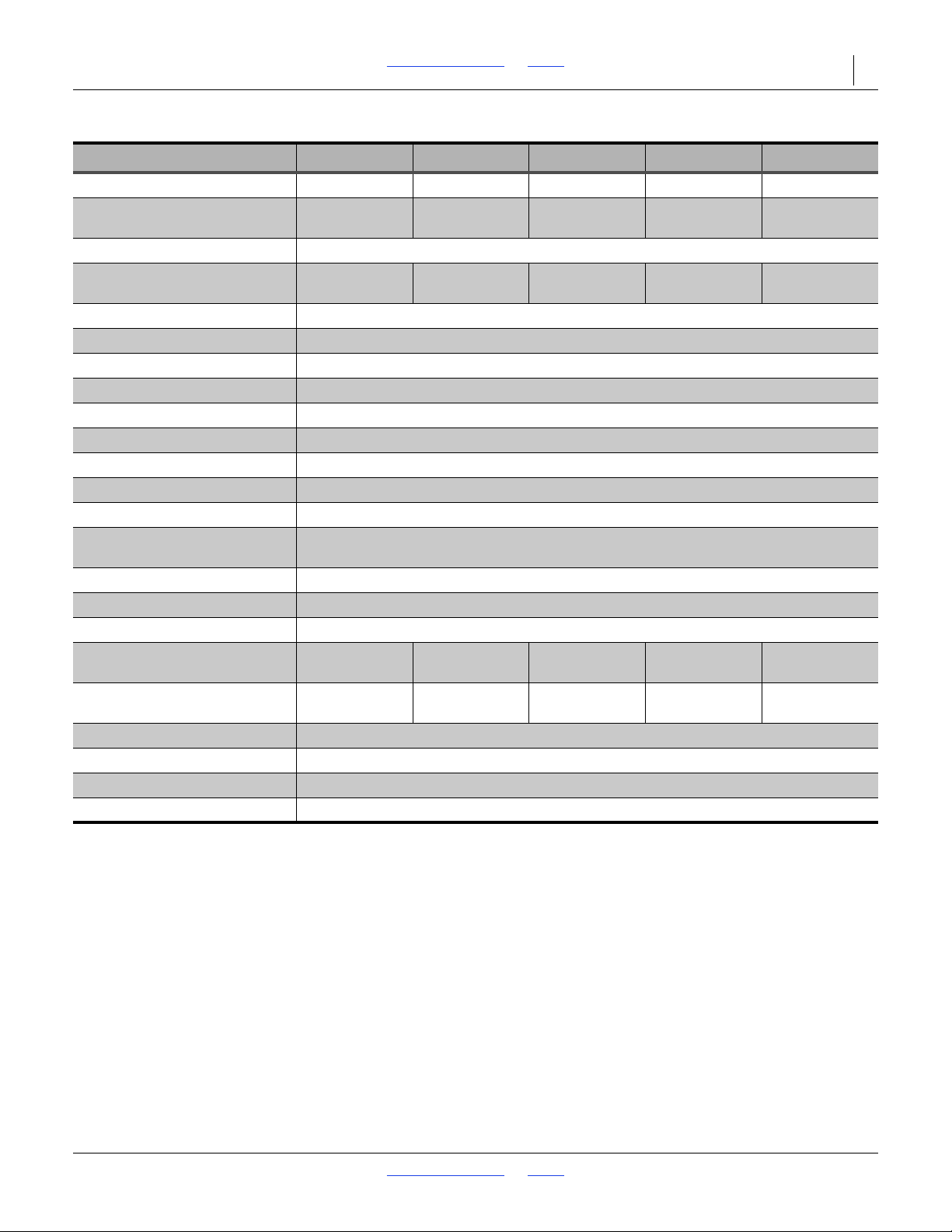
2SF24 and 2SF30 Table of Contents Index Appendix A - Reference Information 66
30-Foot (9.1 m) Models 2SF30-3610 2SF30-4408 2SF30-4875 2SF30-5207 2SF30-6006
Row Count 36 44 48 52 60
Row Spacing 10 inches
(25.4 cm)
8.0 inches
(20 cm)
7.5 inches
(19 cm)
7 inches
(17.8 cm)
6 inches
(15.2 cm)
Working Width 30 feet (9.14 m)
Swath (Channel Width) 360 inches
(914.4 cm)
352 inches
(894.1 cm)
360 inches
(914.4 cm)
364 inches
(924.6 cm)
360 inches
(914.4 cm)
Seed Capacity 60 bushels (2110 liters)
Fertilizer Capacity 30 cubic feet (1060 liters)
Small Seed Capacity 7.2 bushels (250 liters)
Transport Width 14 feet (4.27 m)
Working Length 23 feet 2 inches (7.06 m)
Transport Length 19 feet 4 inches (5.89 m)
Working Height 6 feet 4 inches (1.92 m)
Transport Height 7 feet 7 inches (231 cm)
Transport Clearance 19 inches (48 cm)
Minimum Tractor
Requirement
140 hp (104 kW)
Hitch Pull Type, Large Diameter, Small Clevis or Small Strap
Hydraulic Circuits Required Closed or Open Center, 2 or 3 Remotes
Hydraulic Power Required 2250 psi (155 bar) at 5 gallons/minute (19 liters/minute)
Weight
(minimum, empty)
Weight
(maximum, full
8,300 pounds
(3800 kg)
17,700 pounds
(8000 kg)
8,600 pounds
(3900 kg)
17,900 pounds
(8100 kg)
8,800 pounds
(4000 kg)
18,100 pounds
(8200 kg)
9,100 pounds
(4100 kg)
18,400 pounds
(8300 kg)
9,600 pounds
(4400 kg)
18,900 pounds
(8600 kg)
Transport Tire Size 9.5Lx15 12 Ply Tubeless
Wing Gauge Wheel Tire Size 9.5L-15SL 8 Ply
Opener Down Pressure 90 to 180 pounds (40 to 80 kg)
Opener Depth Range 4 inches (8.9 cm) in 1/4 inch (6.4 mm) increments
2018-08-02 Table of Contents Index 155-015M-A
Page 71
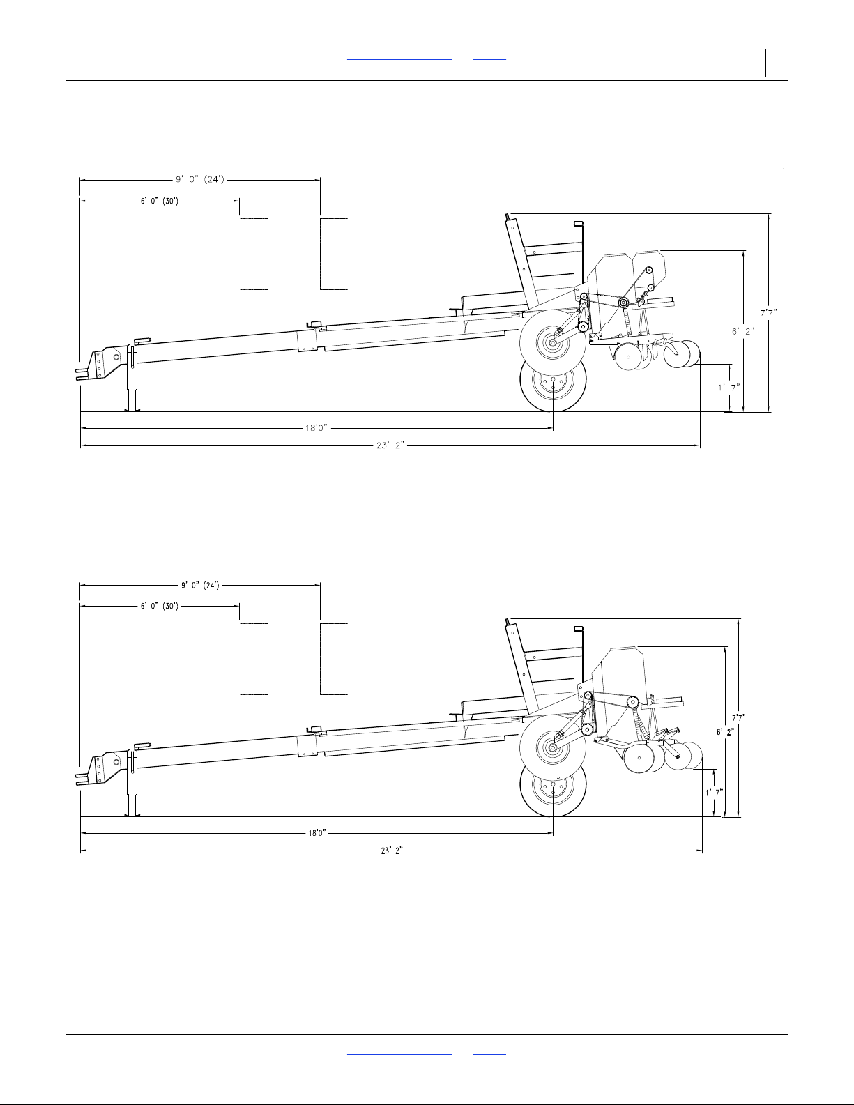
2SF24 and 2SF30 Table of Contents Index Appendix A - Reference Information 67
10242
Dimensions Transport
2018-08-02 Table of Contents Index 155-015M-A
Page 72
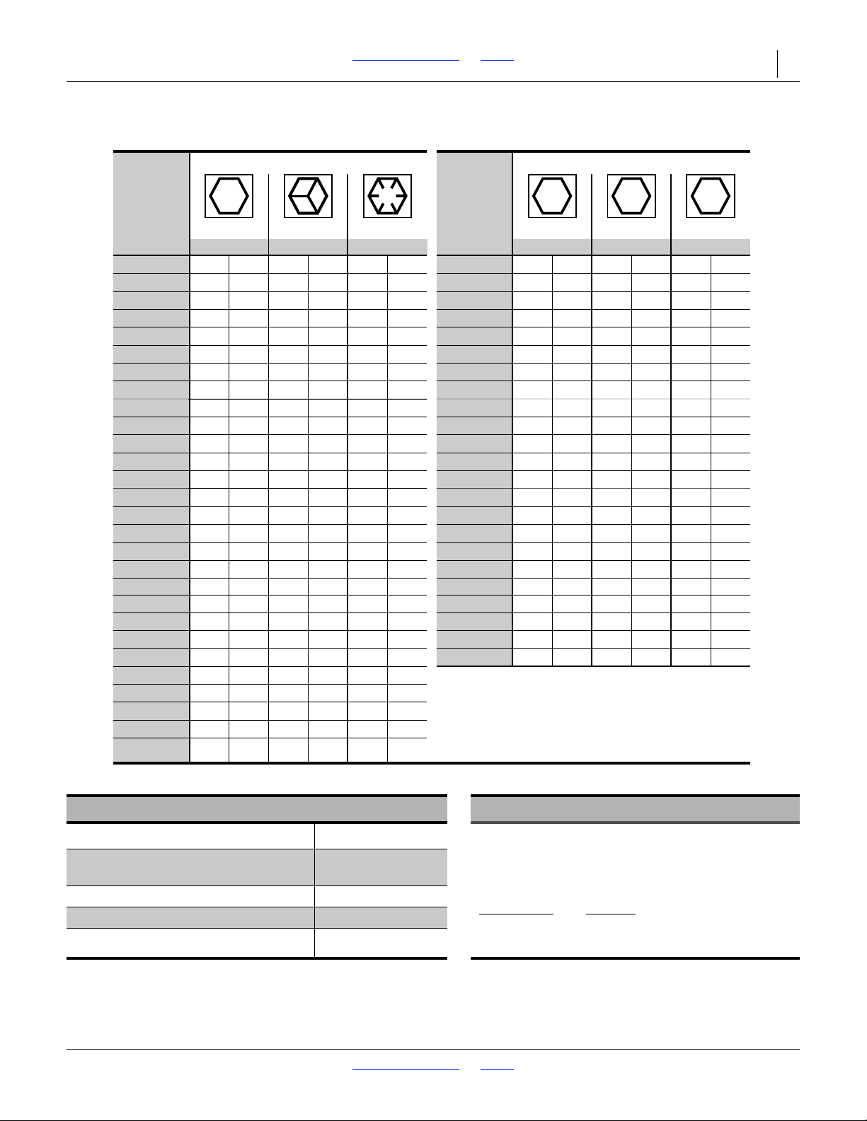
2SF24 and 2SF30 Table of Contents Index Appendix A - Reference Information 68
946
25199m
Bolt
Size
Bolt Head Identification
Bolt
Size
Bolt Head Identification
Grade 2 Grade 5 Grade 8 Class 5.8 Class 8.8 Class 10.9
in-tpi
a
N-m
b
N-m N-m
mm x pitch
c
N-m N-m N-m
1
⁄4-20
7.4 11 16
M 5 X 0.8
1
⁄4-28
8.5 13 18
M 6 X 1
71115
5
⁄16-18
15 24 33
M 8 X 1.25
17 26 36
5
⁄16-24
17 26 37
M 8 X 1
18 2839
3
⁄8-16
27 42 59
M10 X 1.5
33 52 72
3
⁄8-24
314767
M10 X 0.75
396185
7
⁄16-14
43 67 95
M12 X 1.75
58 91 125
7
⁄16-20
49 75 105
M12 X 1.5
60 95 130
1
⁄2-13
66 105 145
M12 X 1
90 105 145
1
⁄2-20
75 115 165
M14 X 2
92 145 200
9
⁄16-12
95 150 210
M14 X 1.5
99 155 215
9
⁄16-18
105 165 235
M16 X 2
145 225 315
5
⁄8-11
130 205 285
M16 X 1.5
155 240 335
5
⁄8-18
150 230 325
M18 X 2.5
195 310 405
3
⁄4-10
235 360 510
M18 X 1.5
220 350 485
3
⁄4-16
260 405 570
M20 X 2.5
280 440 610
7
⁄8-9
225 585 820
M20 X 1.5
310 650 900
7
⁄8-14
250 640 905
M24 X 3
480 760 1050
1-8
340 875 1230
M24 X 2
525 830 1150
1-12
370 955 1350
M30 X 3.5
960 1510 2100
1
1
⁄8-7
4801080 1750
M30 X 2
1060 16802320
1
1
⁄8-12
540 1210 1960
M36 X 3.5
1730 2650 3660
1
1
⁄4-7
680 1520 2460
M36 X 2
1880 2960 4100
1
1
⁄4-12
750 16802730
1
3
⁄8-6
890 1990 3230
a. in-tpi = nominal thread diameter in inches-threads per inch
1
3
⁄8-12
1010 2270 3680
b. N· m = newton-meters
1
1
⁄2-6
1180 2640 4290
1
1
⁄2-12
1330 2970 4820
c. mm x pitch = nominal thread diameter in mm x threadpitch
To rque tolerance + 0%, -15% of torquing values. Unless otherwise specified use torque values listed above.
5.88.8 10.9
25199
ft-lb
d
ft-lb ft-lb ft-lb ft-lb ft-lb
5.6 8 12
61014 5 8 11
11 17 25 12 19 27
13 19 27 13 21 29
20 3144 243953
22 3549 294562
324970 426793
365578 44 70 97
49 76 105 66 77 105
55 85 120 68 105 150
70 110 155 73 115 160
79 120 170 105 165 230
97 150 210 115 180 245
110 170 240 145 230 300
170 265 375 165 260 355
190 295 420 205 325 450
165 430 605 230480 665
185 475 670 355 560 780
250 645 910 390 610 845
275 705 995 705 1120 1550
355 795 1290 785 1240 1710
395 890 1440 1270 1950 2700
500 1120 1820 1380 2190 3220
555 1240 2010
655 1470 2380
745 1670 2710
870 1950 3160
d. ft-l
b = foot pounds
980 2190 3560
3 57
Torque Values Chart
9.5L x 15” 12 Ply Rib Implement t
2018-08-02 Table of Contents Index 155-015M-A
9.5L x 15” 8 Ply Rib Implement (SV)
11L x 15” 12 Ply Rib Implement 44 psi (303 kPa)
Tire Inflation Chart Tire Warranty Information
Tire Size Inflation
44 psi (303kPa)
44 psi (303kPa)
All tires are warranted by the original manufacturer of the
tire. Tire warranty information is found in the brochures
included with your Operator’s and Parts Manuals or
online at the manufacturer’s web sites listed below. For
assistance or information, contact your nearest
Authorized Farm Tire Retailer.
Manufacturer
Firestone www.firestoneag.com
Gleason www.gleasonwheel.com
Titan www.titan-intl.com
Web site
Page 73

2SF24 and 2SF30 Table of Contents Index 69
Appendix B - Assembly and Setup
Before You Start
Read and understand the operator’s manual for your drill.
A basic understanding of how the drill works will aid in
the assembly and setup of your drill.
Before attempting to assemble the drill use the following
as a check list. Having all the needed parts and
equipment readily at hand will speed up your assembly
task and will make the job as safe as possible.
Check for all major frame components.
Check for fasteners and pins that were shipped with
the drill.
NOTE:
All hardware coming from the factory has been
installed in the location where it will be used. If a part
or fastener is temporarily removed for assembly
reasons, remember where it goes. Keep the parts
separated.
If a pin, bolt or other part has been removed and you
are unsure where it is used, use the parts manual to
identify it. Be sure the part gets used in the correct
location.By double checking while you assemble,
you will lessen the chance of using a bolt incorrectly
that may be needed later.
Have a forklift or loader along with chains and safety
stands that are sized for the job ready for the
assembly task.
Have a tractor with remote hydraulics ready to attach
to the tongue. The tongue must be anchored to a
large enough tractor to overcome the negative
tongue weight that will be present when the boxes
are attached to the frame. The hydraulics will aid in
raising and lowering the drill to align pins and bolts
during assembly.
Negative Tongue Weight Hazard:
Be familiar with the term NEGATIVE TONGUE WEIGHT. Be
aware of the special precautions you should take when
working with an implement that can develop Negative Tongue
Weight.
Have a minimum of two people on hand while
assembling the drill.
Drill Assembly
Refer to Figure 48 on page 71.
1. Read and understand the previous section titled:
Before You Start.
2. Read “Important Safety Information” on page 1,
before assembling drill.
3. Set the tongue (1) approximately 21 inches off the
ground in a horizontal position with stable blocking
for support.
4. Raise the mainframe (2) up, keeping the side
members horizontal. Position the mainframe over the
tongue and lower into position.
5. Secure tongue to main frame with six 1 x 2
long bolts (3), lock washers and nuts.
6. Attach the tongue screw jack (4) in a vertical position
and remove blocking so the unit is on the ground.
7. Remove the safety wires from each hydraulic
cylinder rod clevis between the tires.
8. Slide the hydraulic hoses from the mainframe
through the tongue and pull them out at the tractor
end. Attach tractor male couplers to the hydraulic
hoses.
9. Hook tractor up to the tongue and plug hydraulic
connectors into the tractor.
a. With tractor running at an idle speed charge the
drill hydraulic system. Be sure tractor has plenty
of hydraulic fluid. (This system requires
approximately 3.3 gallons.)
b. When the drill frame is raised for the first time,
one lift cylinder will extend fully before the other
one begins to move.
c. Once the first cylinder is fully extended continue
to hold the tractor valve in the same position for
at least 60 seconds after the second lift cylinder
has fully extended.
The reason for the unevenness of raising for the
first time is because the drill is equipped with
master and slave rephasing cylinders.
d. Raise and lower the frame several times to be
sure there is no binding or problems with your lift
system. Refer to “Hitching Tractor to Drill” on
page 14, for additional information.
10. Attach the gauge-wheel turnbuckle (5) to the
gauge-wheel arm (6) on each drill and then mount
the wheel (7) and tire.
1
/2inch
2018-08-02 Table of Contents Index 155-015M-A
Page 74

2SF24 and 2SF30 Table of Contents Index Appendix B - Assembly and Setup 70
141516
21
11. Position the two drill boxes in line, end to end, with
the end chain drive sprockets outboard and
approximately 3 inches between the drill boxes.
Drills on 8 inch row spacing and narrower will have
8 inch spacing at disks between boxes.
12. Using the tractor, back the drill main frame up to the
center of the two drill boxes (8).
a. When close, position the posts (9) on each side
of the mainframe so the face of the post
mounting angles are toward the drill frames.
b. Attach the post (9) to the drill frames using eight
5/8 x 3
1
/2 X 5 inch long U-bolts (10), lock
washers (11), and nuts (12).
c. With the U-bolts left loose, slide the drill frames
inward so that the lugs (13) welded to the drill
frames are up tight against the post angles.
d. Tighten all the nuts on the U-bolts.
13. Attach frame adjustment link from the drill frame
to the pivot post using the clevis pin with hairpin
cotters.
Pin to pin should be approximately 37 inches.
14. Locate drill transport stabilizer frame (16)
1
86
/2inches from the outside edge of each box
frame.
5
a. Using
/8 inch U-bolts (17), lock washers (18)
and nuts (19), mount stabilizer to box frame.
b. Repeat for other side.
15. Adjust clevis end of pull bars (20) so that the
distance from the center line to center line of pull bar
pin holes is approximately 134
1
/4 inches.
16. Mount pull bars to drill transport stabilizer frames
and tongue slide . With the tongue slide in the
back position against its stop, adjust pull bar lengths
so boxes are in line with one another and parallel to
the back edge of the mainframe.
17. Extend the main lift cylinder (22) and place the
transport lock pins (23) in the transport position
through the holes in the mainframe axle side tube.
18. Fold the drill making sure that the tongue slide (21)
moves smoothly up the tongue.
a. When drill boxes are almost folding in, stop and
adjust the post-frame adjustment links on each
box so that the tang (24) on each drill transport
stabilizer frame lines up with the nest (25) on the
front of the main frame.
b. Fold drill completely closed.
19. With tongue slide forward on the tongue and drill
folded completely, position the pull bar lock pin (26)
across the top of the tongue slide. Adjust the
transport lock bolt (27) on top and front of tongue up
against lock pin with
1
/16 inch clearance and lock the
jam nut. This pin prevents the drill from unfolding
when in transport.
Do not lower drill while in folded position, certain equipment
damage will occur.
20. Check to see that all nuts are tightened. See
“Torque Values Chart” on page 68, for torque
specifications.
2018-08-02 Table of Contents Index 155-015M-A
Page 75
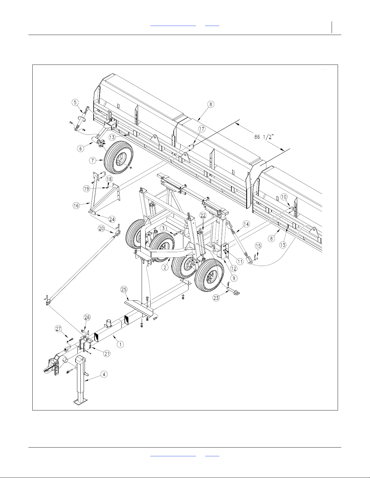
2SF24 and 2SF30 Table of Contents Index Appendix B - Assembly and Setup 71
Figure 48
Assembly Diagram
11505
Assembly Diagram
2018-08-02 Table of Contents Index 155-015M-A
Page 76
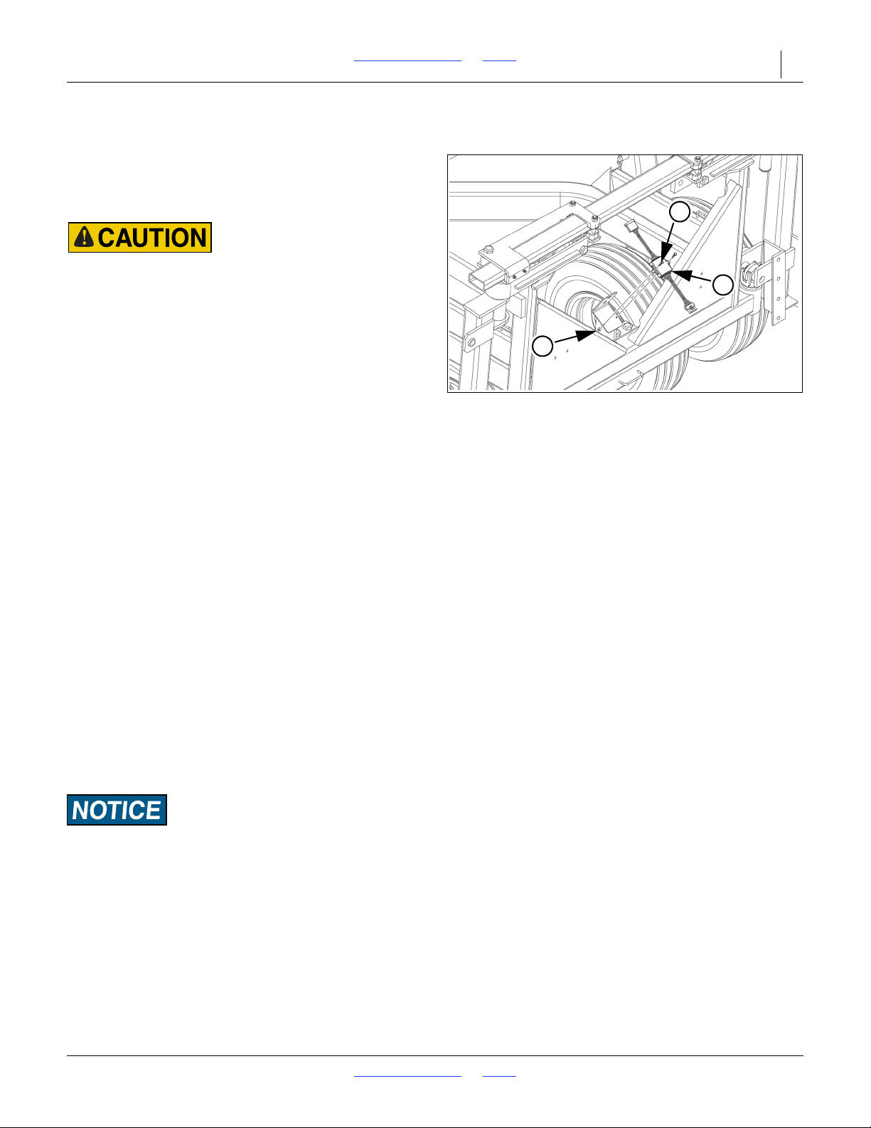
2SF24 and 2SF30 Table of Contents Index Appendix B - Assembly and Setup 72
4
5
3
Figure 49
Install Enhanced Module
68420A
Harness Installation (2SF24 S/N 3509F+) (2SF30 S/N 3974G+)
The red and amber lights should already be installed on
the machine. The enhanced module and machin
wishbone harness will need to be installed to connect the
lights.
Harness Damage Hazard:
Make sure all wiring harnesses are secured to the machine to
prevent damage to the harnesses which can result in injury to
the operator or damage to the machine.
Refer to Figure 49 and Figure 50 on the next page.
The main wiring harness (1) with 7-pin plug (2) will
already be installed inside the tongue.
1. Install the enhanced module (3) to the rear of the
mainframe as shown. Secure with two 1/4-20 x 1 1/4
inch bolts (4) and flange nuts (5).
2. Plug in the main wiring harness coming from the rear
of the tongue to the enhanced module.
3. Connect the wishbone harness (6) to the other end
of the enhanced module. Make sure to position the
wishbone harness so it can be routed as follows:
• The wires with green tape will be routed to the
right-hand side of the machine.
• The wires with yellow tape will be routed to the
left-hand side of the machine.
4. Route the wishbone harness to the red lights.
5. Plug in the three pin connectors (7) to the red lights.
6. Route the two pin wire lead (8) to the amber lights.
Some wire ties, connecting the two and three pin
wire leads, may need to be clipped off with side
cutters to route the two pin wire leads.
7. Plug in the two pin connectors (9) to the amber
lights.
8. Secure the wiring harness to the machine with
adhesive backed cord clips (10) and wire ties (11).
Wire Damage Risk:
Make sure all harnesses are secured to machine. To prevent
damage to harnesses, do not stretch wires and do not let wires
drag on the ground. Allow enough harness length for folding
and unfolding machine, and watch for any pinch points.
2018-08-02 Table of Contents Index 155-015M-A
Page 77
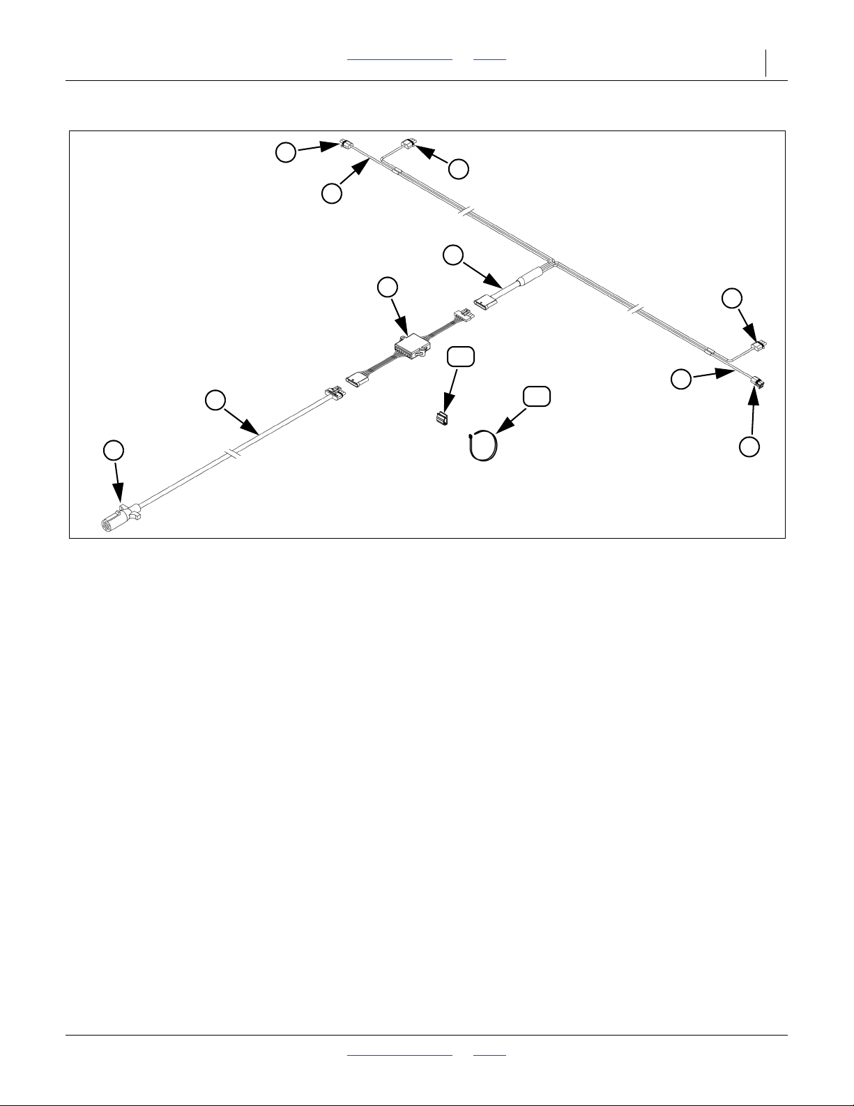
2SF24 and 2SF30 Table of Contents Index Appendix B - Assembly and Setup 73
6
9
3
1
2
7
8
8
7
9
10
11
Figure 50
Harness Routing Diagram
68420
2018-08-02 Table of Contents Index 155-015M-A
Page 78
2SF24 and 2SF30 Table of Contents Index 74
ALFALFA OR RAPE
SEED RATE INDICATOR SETTING NUMBER
DRIVE TYPE 2 0 5 10 15 20 25 30 35404550556065707580 859095100
Row Spacing Kilograms Per Hectare
15.2 cm (6”) 0 4 7 9 12 16 19 22 26 29 33 36 394145475053 56 58 61
17.8 cm (7”)03 6 8 11 15 17 20 22 26 2831 34 36 38 41 44 46 48 50 52
19.1 cm (7.5”)03 6 8 10 13 16 18 20 24 26 29 31 34 36 38 40 43 45 46 48
20.3 cm (8”)03 4 7 9 12 15 17 19 21 25 27 29 30 33 35 3 7 394043 44
25.4 cm (10”)023 6 8 10 11 1
3 16 18 20 21 24 25 27 2830 31 34 35 36
BARLEY
SEED RATE INDICATOR SETTING NUMBER
DRIVE TYPE 1 0 5 10 15 20 25 30 35404550556065707580 859095100
Row Spacing Kilograms Per Hectare*
15.2 cm (6”)008 16 22 30 3744495662697684 92 99 104 111 114 118 120
17.8 cm (7”)00713 20 26 31 38 43 49 54 61 66 7380 85919699102104
19.1 cm (7.5”)0071218 24 29 35404549566267747884 89919496
20.3 cm (8”) 0 0 6 11 17 22 27 31 37414552566267727682 84 86 89
25.4 cm (10”) 004913 18 22 26 30 34 37414650555963 66 68 71 72
* Based on 0.6 kg/liter
BUCKWHEAT
SEED RATE INDICATOR SETTING NUMBER
DRIVE TYPE 1 0 5 10 15 20 25 30 35404550556065707580 859095100
Row Spacing Kilograms Per Hectare
15.2 cm (6”)09162233 374553 62 69 7886 95 105 114 124 132139143 150 155
17.8 cm (7”)08 13 19 25 33 38 45 53 61 68 75 82 91 99 109 114 120 124 130135
19.1 cm (7.5”)071218 24 29 3641495663 69 76 84 92 100 105 111 114 120 124
20.3 cm (8”) 0 7 1117212733 38 45 50 57 64 69 77 84 92 96 102 105 110 113
25.4 cm (10”)06913 17 22 27 31 374147525763 68 75 80 83 869093
FLAX OR SUDAN
SEED RATE INDICATOR SETTING NUMBER
DRIVE TYPE 2 0 5 10 15 20 25 30 35404550556065707580 859095100
Row Spacing Kilograms Per Hectare
15.2 cm (6”) 02471013 16 18 21 24 27 29 33 36 3943 47 50 53 53 54
17.8 cm (7”)023 691113 16 18 20 24 26 2831 34 374044464646
19.1 cm (7.5”)023 6 8 10 12 15 17 19 21 24 26 29 31 34 37404143 43
20.3 cm (8”)013 6 8 10 11 13 16 18 19 21 24 26 29 31 35 37 38 39 39
25.4 cm (10
”) 012468 9 1112151618 20 21 24 26 2830 31 31 33
Appendix M - Metric Charts
Metric Seed Rate Charts
2018-08-02 Table of Contents Index 155-015M-A
Page 79
2SF24 and 2SF30 Table of Contents Index Appendix M - Metric Charts 75
MILLET
SEED RATE INDICATOR SETTING NUMBER
DRIVE TYPE 2 0 5 10 15 20 25 30 35404550556065707580 859095100
Row Spacing Kilograms Per Hectare
15.2 cm (6”)03 6 8 11 13 17 20 24 27 29 34 36404448 53 56 58 59 59
17.8 cm (7”) 02479121518 20 24 26 29 31 35 38 41 45 48 50 52 52
19.1 cm (7.5”)024791113 16 19 21 24 27 29 33 35 38 41 45 47 58 47
20.3 cm (8”)023 6 8 10 12 15 17 19 21 25 27 29 33 35 38 40 43 44 44
25.4 cm (10”)023 478 10 12 15 16 18 20 21 24 26 29 31 34 35 3
6 36
MILO
SEED RATE INDICATOR SETTING NUMBER
DRIVE TYPE 2 0 5 10 15 20 25 30 35404550556065707580 859095100
Row Spacing Kilograms Per Hectare*
15.2 cm (6”)03 6913 17 20 24 27 30 34 38 41 46 50 55 61 64 67 67 68
17.8 cm (7”)0248 11 13 17 20 24 27 29 33 36404447525658 58 59
19.1 cm (7.5”) 0 2 4 7 10 12 16 18 21 25 27 30 34 37404448 52 54 54 55
20.3 cm (8”)023 7 9 11 15 17 20 22 25 2830 34 37404447494950
25.4 cm (10”)023 6 8 10 12 13 16 18 20 22 25 2830 33 36 38 40 40 41
* Based on 0.8 kg/liter
OATS OR SAFFLOWER
SEED RATE INDICATOR SETTING NUMBER
DRIVE TYPE 1 0 5 10 15 20 25 30 35404550556065707580 859095100
Row Spacing Kilograms Per Hectare*
15.2 cm (6”) 0 4 9 16 21 2835414957647280 8593 101 108 114 120 126 130
17.8 cm (7”)048 13 18 25 30 3643 49 55 62 68 74 81 8793 99 104 109 112
19.1 cm (7.5”)03812 17 22 2833394650576468 75 81 869195100104
20.3 cm (8”)03 7 1116212630 36414653 58 63 68 74 7
884 879295
25.4 cm (10”)03 6 9 12 17 21 25 29 35 38 43 47 52 56 61 65 68 72 75 78
* Based on 0.46 kg/liter
PEAS
SEED RATE INDICATOR SETTING NUMBER
DRIVE TYPE 1 0 5 10 15 20 25 30 35404550556065707580 859095100
Row Spacing Kilograms Per Hectare
15.2 cm (6”) 0 0 1129466278 92 106 123 138 151 168 183 197 212 229 241 254 263 270
17.8 cm (7”)009263954688092108 120 131 146 158 170 184198 208 221 229 234
19.1 cm (7.5”)00924374963 74 85 99 111 121 135 146 157 169 183 193 204 211 216
20.3 cm (8”)008 21 344557677791101111123 135 145 156 167 177 187193 198
25.4 cm (10”)00718
27 374755647483 91 101 110 118 127 137 145 152 158 163
2018-08-02 Table of Contents Index 155-015M-A
Page 80
2SF24 and 2SF30 Table of Contents Index Appendix M - Metric Charts 76
PINTO BEANS
SEED RATE INDICATOR SETTING NUMBER
DRIVE TYPE 2 0 5 10 15 20 25 30 35404550556065707580 859095100
Row Spacing Kilograms Per Hectare*
15.2 cm (6”) 00048 13 18 22 27 31 36404649545963 67 71 72 73
17.8 cm (7”)0003 7 111620242730 35 3943 47 52 55 58 62 62 63
19.1 cm (7.5”)0003 7101518 21 25 283336 3944475054565758
20.3 cm (8”)0003 61013 17 20 22 26 30 34 36 394446495253 53
25.4 cm (10”) 000248 11 13 16 19 21 25 27 30
33 36 38 40 43 43 44
* Based on 0.77 kg/liter
RICE LONG GRAIN
SEED RATE INDICATOR SETTING NUMBER
DRIVE TYPE 1 0 5 10 15 20 25 30 35404550556065707580 859095100
Row Spacing Kilograms Per Hectare
15.2 cm (6”) 0 7 11172228333844 49 55 61 65 72 82 89 95 102 104 109 112
17.8 cm (7”) 0 6 101519242834 38 43 47 53 56 63 71 77 83 87919498
19.1 cm (7.5”)06913 18 22 26 31 35 394448 52 57 66 71 76 81 83 8790
20.3 cm (8”) 0 4 9 12 16 20 24 28333640454753 61 65 71 74 76 80 83
25.4 cm (10”)0471013 17 19 24 26 29 33 36 39444953 57 61 63 65 67
RICE LONG GRAIN
SEED RATE INDICATOR SETTING NUMBER
DRIVE TYPE 1A 0 5 10 15 20 25 30 35404550556065707580 859095100
Row Spacing Kilograms Per Hectare
15.2 cm (6”)013 24 3545566780 90 102 112 123 133 148 168 182 196 207 214 224 231
17.8 cm (7”) 0 12 21 30 394958 68 77 8798 108 115 128 146 158 170 179 185194201
19.1 cm (7.5”) 0 11 19 28364554647281 90 100 106 118 135 146 157 166 171 179 185
20.3 cm (8”)01018 26 33 41 49 58 66 74 83 91 98 109 123 1
33 145 151 157 164 169
25.4 cm (10”)08 15 20 27 3440475461677480 89 101 109 118 124 129 135139
RICE SHORT GRAIN
SEED RATE INDICATOR SETTING NUMBER
DRIVE TYPE 1 0 5 10 15 20 25 30 35404550556065707580 859095100
Row Spacing Kilograms Per Hectare
15.2 cm (6”)08 15 20 26 34 3947525764697483 93 101 110 115 120 126 129
17.8 cm (7”)071218 22 29 354044495561647281 87 95 101 104 109 112
19.1 cm (7.5”) 0 7 1116212731 374046505659667481 8 793 95 101 103
20.3 cm (8”) 0 6 101519252935 37414652556268 74 81 85 879295
25.4 cm (10”) 0 4 9 12 16 20 24 2830 35 38 41 45 50 56 61 66 69 72 75 77
2018-08-02 Table of Contents Index 155-015M-A
Page 81
2SF24 and 2SF30 Table of Contents Index Appendix M - Metric Charts 77
RICE SHORT GRAIN
SEED RATE INDICATOR SETTING NUMBER
DRIVE TYPE 1A 0 5 10 15 20 25 30 35404550556065707580 859095100
Row Spacing Kilograms Per Hectare
15.2 cm (6”) 0 17 29 41 54 6882 95 104 117 130143 152 171 189 207 225 238 245 258 266
17.8 cm (7”) 0 15 26 3647597183 91 102 113 124 132148 165 179 196 206 213 223 230
19.1 cm (7.5”)013 24 344455657684 94 104 115 122 137 152 166 180 196 206 212 103
20.3 cm (8”) 0 6 101519252935 37414652556268 74 81 85 879295
25.4 cm (10”) 0 4 9 12 16 20 24 2830 35
38 41 45 50 56 61 66 69 72 75 77
RYE
SEED RATE INDICATOR SETTING NUMBER
DRIVE TYPE 2 0 5 10 15 20 25 30 35404550556065707580 859095100
Row Spacing Kilograms Per Hectare
15.2 cm (6”)03 7 9 12 16 18 20 22 26 2831 34 374043 45 47 48 52 53
17.8 cm (7”)03 6 8 10 13 15 18 20 22 25 27 29 33 35 37 394043 45 46
19.1 cm (7.5”)03 6 8 10 12 13 16 18 20 22 25 27 30 33 35 36 38 394043
20.3 cm (8”) 024791112151719212225272931 33 35 36 37 38
25.4 cm (10”) 0246
8 9101213 16 17 19 20 22 24 26 27 28 29 30 31
SOYBEANS
SEED RATE INDICATOR SETTING NUMBER
DRIVE TYPE 1 0 5 10 15 20 25 30 35404550556065707580 859095100
Row Spacing Kilograms Per Hectare*
15.2 cm (6”) 000034456278 94 110 127 142 157 173 186 197 211 224 229 232234
17.8 cm (7”) 00002939546881 95 110 123 137 149 161 171 183 194 198 202 203
19.1 cm (7.5”)000027364963 75 89 102 113 126 138 148 158 168 179 184186187
20.3 cm (8”) 000025344557688193 104 115 127 136 145 155 165 168 170 171
25.4 cm (10
”) 0 0 0 0 20 27 37475666768594103 111 119 127 135138 139140
* Based on 0.76 kg/liter
SOYBEANS
SEED RATE INDICATOR SETTING NUMBER
DRIVE TYPE 2 0 5 10 15 20 25 30 35404550556065707580 859095100
Row Spacing Kilograms Per Hectare*
15.2 cm (6”) 0 0 0 0 11 15 20 26 30 3641465256616468 73 75 76 76
17.8 cm (7”) 000091218 22 27 31 36404548 53 56 59 64 65 66 66
19.1 cm (7.5”)00009121620252934 37414548 52 55 69 59 61 62
20.3 cm (8”) 00008 11 15 19 22 27 30 34 38 41 45 47 50 54 55 56 56
25.4 cm (10”) 000079121618 21 25 2830 34 36 38 41 44 45 46 46
* Based on 0.76 kg/liter
2018-08-02 Table of Contents Index 155-015M-A
Page 82
2SF24 and 2SF30 Table of Contents Index Appendix M - Metric Charts 78
SOYBEANS
SEED RATE INDICATOR SETTING NUMBER
DRIVE TYPE 2A 0 5 10 15 20 25 30 35404550556065707580 859095100
Row Spacing Kilograms Per Hectare*
15.2 cm (6”) 000022304153 63 74 85 95 105 115 124 132 141 150 154 156 157
17.8 cm (7”) 0 0 0 0 19 26 364655647482 91 100 108 115 123 130133 136137
19.1 cm (7.5”)000018 25 3441505968 76 84 92 100 106 113 120 123 124 126
20.3 cm (8”) 0 0 0 0 17 22 30 38 46 54 63 69 77 849298 104 110 113 114 115
25.4 cm (10”) 000013 18 25
31 38 45 50 57 63 69 75 80 8590929494
* Based on 0.76 kg/liter. Setting the feed cup adjustment lever between 50 & 80 allows for optimum seeding of soybeans.
SUNFLOWERS
SEED RATE INDICATOR SETTING NUMBER
DRIVE TYPE 2 0 5 10 15 20 25 30 35404550556065707580 859095100
Row Spacing Kilograms Per Hectare*
15.2 cm (6”) 00023 4 7 9 10 12 16 17 19 21 22 26 27 29 30 31 33
17.8 cm (7”) 0002336 8 91113 15 17 18 20 22 24 25 26 27 28
19.1 cm (7.5”)0001336 7 9 10 12 13 16 17 18 20 21 24 24 25 26
20.3 cm (8”) 000123 678 9 111213 16 17 19 20 21 22 22 24
25.4 cm (10”) 000123 4678 9 10111213 16 16 17 18 19 19
* Based on 0.37 kg/liter
WHEAT
SEED RATE INDICATOR SETTING NUMBER
DRIVE TYPE 1 0 5 10 15 20 25 30 35404550556065707580 859095100
Row Spacing Kilograms Per Hectare*
15.2 cm (6”) 0 12 22 314153 62 738495108 119 130 145 157 171 180 191 196 206 212
17.8 cm (7”) 0 11 19 27 36455463 738293 103 112 124 136148 157 165 170 178 184
19.1 cm (7.5”)01018 26 33 41 49 58 67 76 86 95 104 115 126 137 145 152 157 165 170
20.3 cm (8”)09172430 38 45 54 62 69 7887 95 104 115 126 132139 145 151 156
25.4 cm (10”)08 13 19 25 31 3
74450576572788694103 109 114 118 123 128
* Based on 0.77 kg/liter
WHEAT
SEED RATE INDICATOR SETTING NUMBER
DRIVE TYPE 2A 0 5 10 15 20 25 30 35404550556065707580 859095100
Row Spacing Kilograms Per Hectare*
15.2 cm (6”) 0 9 15212835414956647280 87 96 105 114 121 128 131138 142
17.8 cm (7”)08 12 18 24 30 3643 49 52 63 69 75 84 91 100 105 111 114 120 123
19.1 cm (7.5”) 0 7 1217222834 39455058 64 69 77 84 92 96 102 105 111 114
20.3 cm (8”) 0 7 111620263 0 36414753 58 64 71 77 84 8993 96 101 104
25.4 cm (10”) 0 6 9 12 17 21 25 29 34 38 44 48 53 5
8 63 68 73 76 788385
* Based on 0.77 kg/liter
2018-08-02 Table of Contents Index 155-015M-A
Page 83
2SF24 and 2SF30 Table of Contents Index Appendix M - Metric Charts 79
WHEAT GRASS
SEED RATE INDICATOR SETTING NUMBER
DRIVE TYPE 2 0 5 10 15 20 25 30 35404550556065707580 859095100
Row Spacing Kilograms Per Hectare
15.2 cm (6”) 01223 44678 9 1010111213 15 16 16 17 17
17.8 cm (7”) 01123346678 9 9 10 11 12 12 13 13 15 15
19.1 cm (7.5”)011233446778 9 9 10 11 11 12 12 13 13
20.3 cm (8”) 0112233446778 9 9 10 11 11 11 12 12
25.4 cm (10”) 011122334466778899101010
2018-08-02 Table of Contents Index 155-015M-A
Page 84
2SF24 and 2SF30 Table of Contents Index Appendix M - Metric Charts 80
Alfalfa, Red Alsike, Crimson Clover
Rate Adjuster Setting
Row 5 10 15 20 25 30 35404550556065707580 859095100
Spacing
Seed Rate in Kilograms per Hectare
15.2 cm (6”)02.53.9 5.4 6.7 8.4 9.8 11.0 12.6 14.0 15.5 16.9 18.4 19.6 21 23 24 26 27 28
17.8 cm (7”)02.13.4 4.6 5.7 7.2 8.4 9.4 10.6 12.1 13.2 14.5 15.7 16.8 18.3 19.4212223 24
19.1 cm (7½”)0 2.0 3.1 4.4 5.4 6.7 7.88.9 10.1 11.2 12.4 13.6 14.8 15.7 17.1 18.2 19.3 21 22 23
20.3 cm (8”)01.8 2.9 4.0 5.0 6.3 7.4 8.3 9.4 10.5 11.5 12.7 13.8 14.6 14.7 17.0 1
8.0 19.2 20 21
25.4 cm (10”)01.5 2.4 3.1 3.9 4.9 5.7 6.5 7.4 8.3 9.1 10.0 10.9 11.5 12.6 13.3 14.1 15.0 15.9 16.7
Bermuda, Red Top, Unhulled Lespedeza, Sercia, Sand & Weeping Love Grass
Rate Adjuster Setting
Row 5 10 15 20 25 30 35404550556065707580 859095100
Spacing
Seed Rate in Kilograms per Hectare
15.2 cm (6”)00.8 1.2 1.9 2.9 3.7 4.6 5.6 6.6 7.4 8.1 8.7 9.4 10.1 10.6 11.4 12.2 13.0 13.7 14.5
17.8 cm (7”) 0 0.7 1.0 1.7 2.5 3.1 4.0 4.8 5.7 6.3 6.9 7.5 8.0 8.6 9.1 9.8 10.5 11.2 11.8 12.3
19.1 cm (7½”) 0 0.6 1.0 1.6 2.4 2.9 3.7 4.5 5.3 5.9 6.5 7.1 7.5 8.1 8.5 9.2 9.9 10.4 11.0 11.7
20.3 cm (8”) 0 0.6 0.9 1.5 2.2 2.83.5 4.3 4.9 5.5 6.1 6.6 7.3 7.5 8.0 8.5 9.2 9.
8 10.3 10.9
25.4 cm (10”) 0 0.4 0.7 1.1 1.7 2.1 2.7 3.4 3.9 4.4 4.7 5.2 5.5 5.9 6.3 6.7 7.2 7.6 8.1 8 .5
Birdsfoot, Trefoil, Sudan
Rate Adjuster Setting
Row 5 10 15 20 25 30 35404550556065707580 859095100
Spacing
Seed Rate in Kilograms per Hectare
15.2 cm (6”)01.93.7 5.8 7.6 9.8 12.0 14.2 16.5 18.8 22 24 26 29 31 34 36 38 41 43
17.8 cm (7”)01.73.1 5.0 6.5 8.4 10.3 12.2 14.0 16.1 18.5 20 22 25 27 29 31 33 35 37
19.1 cm (7½”) 0 1.6 2.9 4.7 6.1 7.8 9.6 11.4 13.3 15.1 17.3 19.1 21 23 25 27 29 31 33 35
20.3 cm (8”)01.52.8 4.4 5.7 7.4 9.1 10.6 12.3
14.1 16.1 17.8 19.6 22 24 25 27 29 30 32
25.4 cm (10”)01.1 2.1 3.5 4.5 5.7 7.1 8.4 9.6 11.1 12.7 14.0 15.5 16.9 18.5 19.7 21 23 24 25
Canola, Ladino Clover, Canary Grass, Timothy
Rate Adjuster Setting
Row 5 10 15 20 25 30 35404550556065707580 859095100
Spacing
Seed Rate in Kilograms per Hectare
15.2 cm (6”)01.22.43.7 5.3 6.88.5 10.3 12.0 13.7 15.5 17.4 19.1 21 23 24 26 2831 33
17.8 cm (7”)01.01.93.1 4.6 5.8 7.4 8.9 10.3 11.8 13.2 14.9 16.4 17.8 19.52122252628
19.1 cm (7½”)0 1.0 1.8 2.9 4.4 5.5 6.88.3 9.6 11.0 12.4 14.0 15.4 16.7 18.3 19.7 21 23 25 26
20.3 cm (8”) 0 0.9 1.7 2.8 4.0 5.2 6.4 7.7 9.0 10.3 11.5 13.0 14.3 15.6 17.0 18.4 19.6 21 2
3 25
25.4 cm (10”) 0 0.7 1.7 2.1 2.8 4.0 5.0 6.1 7.1 8.1 9.1 10.2 11.2 12.2 13.5 14.5 15.5 16.7 18.0 19.3
Metric Small Grass Seed Charts
2018-08-02 Table of Contents Index 155-015M-A
Page 85
2SF24 and 2SF30 Table of Contents Index Appendix M - Metric Charts 81
Red & Sweet Clover, Lespedeza Hulled
Rate Adjuster Setting
Row 5 10 15 20 25 30 35404550556065707580 859095100
Spacing
Seed Rate in Kilograms per Hectare
15.2 cm (6”)01.73.8 5.88.0 10.1 12.7 14.8 17.1 19.1 21 23 25 27 30 32 34 36 38 40
17.8 cm (7”)01.53.3 5.0 6.88.6 10.9 12.7 14.7 16.4 18.3 20 22 24 25 28 29 3 1 33 34
19.1 cm (7½”)0 1.33.0 4.7 6.4 8.1 10.2 11.9 13.8 15.4 17.1 18.7 20 22 24 25 27 29 30 32
20.3 cm (8”)01.22.
8 4.4 5.9 7.5 9.5 11.1 12.9 14.3 16.0 17.5 18.9 21 22 24 25 27 2830
25.4 cm (10”)01.0 2.2 3.5 4.7 5.9 7.5 8.7 10.1 11.2 12.6 13.7 14.9 16.1 17.5 18.6 20 21 22 23
Kentucky Blue Grass, Fescue, Annual Rye Grass
Rate Adjuster Setting
Row 5 10 15 20 25 30 35404550556065707580 859095100
Spacing
Seed Rate in Kilograms per Hectare
15.2 cm (6”)00.21.3 2.1 3.0 3.7 4.6 5.2 5.8 6.5 7.1 7.6 8.2 8.7 9.3 9.9 10.3 10.9 11.2 11.8
17.8 cm (7”) 0 0.2 1.1 1.8 2.6 3.1 3.9 4.5 5.0 5.6 6.1 6.6 7.1 7.5 8.0 8.4 8.9 9.0 9.6 10.1
19.1 cm (7½”) 0 0.2 1.0 1.7 2.5 3.0 3.7 4.1 4.7 5.2 5.7 6.2 6.6 7.1 7.5 7.88.38.6 9.1 9.4
20.3 cm (8”) 0 0.2 1.0 1.6 2.2 2.83.4 3.9 4.4 4.8 5.4 5.7 6.2 6.6 6.9 7.4 7.7 8.4 8.4 8.9
25.4 cm (10”)00.1 0.8 1.2 1.8 2.2 2.7 3.0 3.5 3.8 4.1 4.5 4.8 5.2 5.5 5.8 6.1 6.4 6.6 6.9
Millet, Reed Canary
Rate Adjuster Setting
Row 5 10 15 20 25 30 35404550556065707580 859095100
Spacing
Seed Rate in Kilograms per Hectare
15.2 cm (6”)0.41.62.73.9 4.9 6.2 7.38.4 9.5 10.6 11.8 12.9 14.0 15.2 16.4 17.5 18.6 19.7 21 21
17.8 cm (7”)0.41.3 2.4 3.4 4.3 5.3 6.3 7.2 8.2 9.1 10.1 11.1 12.0 13.0 14.0 14.9 15.9 16.9 17.8 18.0
19.1 cm (7½”)0.3 1.3 2.2 3.1 4.0 4.9 5.8 6.7 7.6 8.5 9.4 10.4 11.3 12.2 13.1 14.0 14.9 15.8 16.7 16.9
20.3 cm (8”)0.3 1.2 2.0 2.9 3.7 4.6 5.5 6.3 7.2 8.0 8.9 9.6 10.5 11.4 12.2 13.1 1
3.9 14.8 15.6 15.8
25.4 cm (10”)0.3 0.9 1.6 2.2 2.9 3.6 4.3 4.9 5.6 6.3 6.9 7.6 8.3 9.0 9.6 10.3 11.0 11.7 12.2 12.9
Orchard Grass
Rate Adjuster Setting
Row 5 10 15 20 25 30 35404550556065707580 859095100
Spacing
Seed Rate in Kilograms per Hectare
15.2 cm (6”)00 0.3 0.8 1.0 1.5 1.7 2.2 2.7 3.1 3.7 3.9 4.4 4.9 5.4 5.6 6.2 6.4 6.8 7.1
17.8 cm (7”) 0 0 0.2 0.7 0.8 1.2 1.5 1.9 2.4 2.7 3.1 3.4 3.8 4.1 4.6 4.8 5.3 5.6 5.8 6.1
19.1 cm (7½”) 0 0 0.2 0.6 0.8 1.2 1.3 1.8 2.1 2.6 2.9 3.1 3.6 3.9 4.4 4.5 4.9 5.2 5.5 5.7
20.3 cm (8”) 0 0 0.2 0.6 0.8 1.1 1.2 1.7 2.0 2.4 2.8 2.9 3.33.7 4.0 4.3 4.6 4.8 5.2 5.4
25.4 cm (10
”) 0 0 0.1 0.4 0.6 0.9 1.0 1.3 1.6 1.9 2.1 2.4 2.6 2.9 3.1 3.4 3.6 3.7 4.0 4.1
2018-08-02 Table of Contents Index 155-015M-A
Page 86
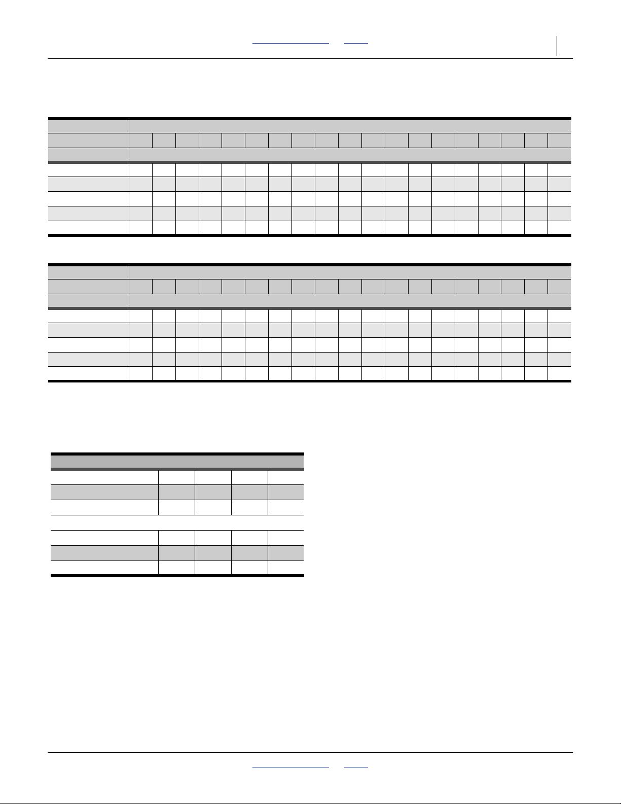
2SF24 and 2SF30 Table of Contents Index Appendix M - Metric Charts 82
Fertilizer
Rate Adjuster Setting
2014+
10 15 20 25 30 35404550556065707580 859095100
Row Spacing Application Rate - Kilograms per Hectare*
15.2 cm (6 in.) 10 15 28 54 75 100 126 147 173 194 221 244 262 293313327 340 343345
17.8 cm (7 in.) 10 15 26 46 64 87 106 124 147 166 185 206 223 248 263 276 287290293
19.1 cm (7.5 in.) 8 12 22 43 61 81 100 118 138 155 176 195 210 234 250 262 271 275 277
20.3 cm (8 in.) 8 12 22 40 56 77 94 110 129 146 164 183 197 219 232 245 253 256 259
25.4 cm (10 in.) 6 9 183345 61 75 89103 117 132 147 157 176 187 196 204 205 207
*Based on 1.04 kg/liter.
Fertilizer
Rate Adjuster Setting
2013-
10 15 20 25 30 35404550556065707580 859095100
Row Spacing Application Rate - Kilograms per Hectare*
15.2 cm (6 in.) 17 26 35547298 122 140 157 188 219 235 252 278303331 359 387414
17.8 cm (7 in.) 15 22 29 43 61 83 104 119 133 160 186 201 214 236258 281 305 328352
19.1 cm (7.5 in.) 13 20 27 41 57 76 98 112 126 150 175 188 202 222 242 265 287 309 331
20.3 cm (8 in.) 12 19 26 40 54 69 92 105 118 141 164 177 189208 228 24
8 269 290 310
25.4 cm (10 in.) 10 16 21 33 43 58 74 8494113 131 141 151 167 182198 217 232248
*Based on 1.04 kg/liter.
Dry Fertilizer Density Adjustment
Pounds/Cubic-Foot
45 50 55 60
Kilograms/Liter
0.72 0.800.88 0.96
Conversion Factor
1.44 1.301.18 1.08
Pounds/Cubic-Foot
65 70 75 80
Kilograms/Liter
1.04 1.12 1.20 1.28
Conversion Factor
1.00 0.93 0.870.81
34755
Metric Fertilizer Rate Charts
Density Conversion Chart
The fertilizer meter rate charts are based on fertilizer with a density of 65 pounds per cubic foot (1.04 kilograms per
liter). If you are applying fertilizer of a different density, use the following table to convert application rate.
Example: Your fertilizer has a density of 75 pounds per cubic foot, and you want to apply 100 pounds per acre. Multiply
the desired application rate by the conversion factor.
100 x 0.87 = 87
Adjust drill to the setting closest to 87 pounds per acre.
2018-08-02 Table of Contents Index 155-015M-A
Page 87
2SF24 and 2SF30 Table of Contents Index Appendix M - Metric Charts 83
Warranty
Great Plains (a division of Great Plains Manufacturing, Inc.) warrants to the
original purchaser that this Great Plains unit will be free from defects in material
and workmanship for a period of one year from the first use date when used as
intended and under normal service and conditions for personal use; ninety days
for custom/commercial or rental use. This Warranty is limited to the replacement
of any defective part by Great Plains and the installation by the dealer of any
such replacement part. Great Plains reserves the right to inspect any equipment
or part which are claimed to have been defective in material or workmanship.
The following items and/or conditions are not covered under warranty:
failures resulting from abuse or misuse of the equipment, failures occurring as a
result of accidental damage or acts of God, failures resulting from alterations or
modifications, failures caused by lack of normal maintenance as outlined in the
operator’s manual, repairs made by non-authorized personnel, items replaced or
repaired due to normal wear (such as wear items and ground engaging
components), repeat repair due to improper diagnosis or repair by the dealer,
temporary repairs, service calls and/or mileage to and from customer location,
overtime premium, or unit hauling expenses. The warranty may be voided if the
unit is towed at speeds in excess of 20 miles per hour (32 kilometers per hour),
or is used in soils with rocks, stumps, or other obstructions.
Great Plains reserves the right to make changes in materials or design of the
product at any time without notice. The warranty shall not be interpreted to
render Great Plains liable for damages of any kind, direct or consequential or
contingent to property. Furthermore, Great Plains shall not be liable for damages
resulting from any cause beyond its control. This warranty does not extend to
crop loss, losses caused by planting or harvest delays or any expense or loss of
labor, supplies, rental machinery, or for any other reason.
No other warranty of any kind whatsoever express or implied, is made with
respect to this sale; and all implied warranties of merchantability and fitness for
a particular purpose which exceed the obligations set forth in this written
warranty are hereby disclaimed and excluded from this sale.
This warranty is not valid unless the unit is registered with Great Plains within
10 days from the date of the original purchase.
38112
2018-08-02 Table of Contents Index 155-015M-A
Page 88

Table of Contents Index
Table of Contents Index
Page 89

2SF24 and 2SF30 Cover Table of Contents 83
Index
A
adjustments ........................................35
amber reflectors ...................................6
Appendix ............................................69
B
blue, hose grip ....................................16
bolt, shear ...........................................59
C
capacities ...........................................65
cap, grease seal .................................59
CAUTION, defined ...............................1
checklists
pre-setup .....................................13
pre-start .......................................24
chemicals .............................................4
children .................................................3
color code, hose ..........................16
covered models ..................................11
customer service ................................12
cylinder symbols ..........................16
,17
,17
D
DANGER, defined ................................1
daytime reflectors .................................7
decal replacement ................................6
decals
caution
PP-HC-MF-24 & 30 ................9
tire damage hazard ................9
notice
lift cyl operating instructions .10
warning
falling hazard ..........................8
negative tongue weight ..........8
speed .....................................8
decal, safety .........................................6
definitions ...........................................11
directions ............................................11
disposal, chemical ................................4
dual marker ........................................31
F
fire ........................................................1
folding .................................................26
G
gauge wheel turnbuckle .....................22
gray, hose grip ....................................16
grease seal cap ..................................59
H
height, hitch ....................20,21, 22, 23
height, tool bar...................... 19
high pressure fluids ..............................2
hitch height .................................. 20, 22
hitching ...............................................14
,21, 48
hydraulic safety .................................... 2
I
inflation............................................... 68
intended usage .................................. 11
L
left-hand, defined ............................... 11
leveling hitch pin .................................. 2
lights..................................................... 3
M
maintenance ...................................... 57
marker......................................... 59
maintenance safety .............................. 5
marker operation ................................ 31
marker shear bolt ............................... 59
Material Safety Data Sheet ................ 24
model number .................................... 12
MSDS................................................. 24
M8x1.25 Class 8.8 ............................. 59
N
Note, defined...................................... 11
NOTICE, defined..........................11,12
O
orientation rose .................................. 11
owner assistance ............................... 12
P
parking ............................................... 30
planting depth adjustments ................ 36
protective equipment............................ 2
R
red reflectors ........................................ 7
reflectors
amber............................................ 6
daytime ......................................... 7
red................................................. 7
SMV .............................................. 6
reflectors, safety................................... 6
repair parts ......................................... 12
riders ................................................2
right-hand, defined ............................. 11
,3
S
safety chain .......................................... 2
safety decal .......................................... 6
safety information................................. 1
safety symbol ....................................... 1
seed flap ............................................ 58
Seed-Lok® ......................................... 63
serial number ..................................... 12
setup .................................................. 13
initial............................................ 13
pre-planting ................................. 13
seasonal ..................................... 13
shutdown.............................................. 4
specifications ......................................65
sprocket arrangements .......................48
storage........................................... 4
symbol, safety.......................................1
,34
T
tables
adjustments .................................35
document family ..........................11
hose color code ....................16
models covered ...........................11
torque values ...............................68
troubleshooting
population ............................55
threaded stud...............................21
tire inflation .........................................68
tires .......................................................4
top slide cylinder .................................23
torque
fastener .......................................68
towing vehicle capability .....................29
transport .............................................29
transport speed.....................................3
two markers out ..................................31
,17
,23
U
URLs, tires ..........................................68
W
WARNING, defined ..............................1
warranty ..............................................68
weight, planter ....................................29
welding .................................................5
wing fold hydraulics .....................19
,21
Numerics
113-196A, marker ...............................62
113-197A, marker ...............................62
113-200A, marker ...............................62
113-201A, marker ...............................62
2SF24-2810 ........................................11
2SF24-3608 ........................................11
2SF24-3875 ........................................11
2SF24-4007 ........................................11
2SF24-4806 ........................................11
2SF30-4875 ........................................11
2SF30-5207 ........................................11
2SF30-6006 ........................................11
802-012C, bolt ....................................59
803-011C, nut .....................................59
818-019C, decal ...................................8
818-020C, decal ...................................9
818-043C, decal ............................ 9
818-055C, reflector ...............................6
818-188C, decal ...................................8
818-587C, decal ...................................9
838-102C, decal ...................................8
,10
2018-08-02 Cover Table of Contents 155-015M-A
Page 90

2SF24 and 2SF30 Cover Table of Contents 84
838-265C, reflector ...............................6
838-266C, reflector ...............................7
838-267C, reflector ...............................7
890-840C, Keeton ..............................63
2018-08-02 Cover Table of Contents 155-015M-A
Page 91

Table of Contents Index
Table of Contents Index
Page 92

Great Plains, Mfg.
1525 E. North St.
P.O. Box 5060
Salina, KS 67402
 Loading...