

Page 1
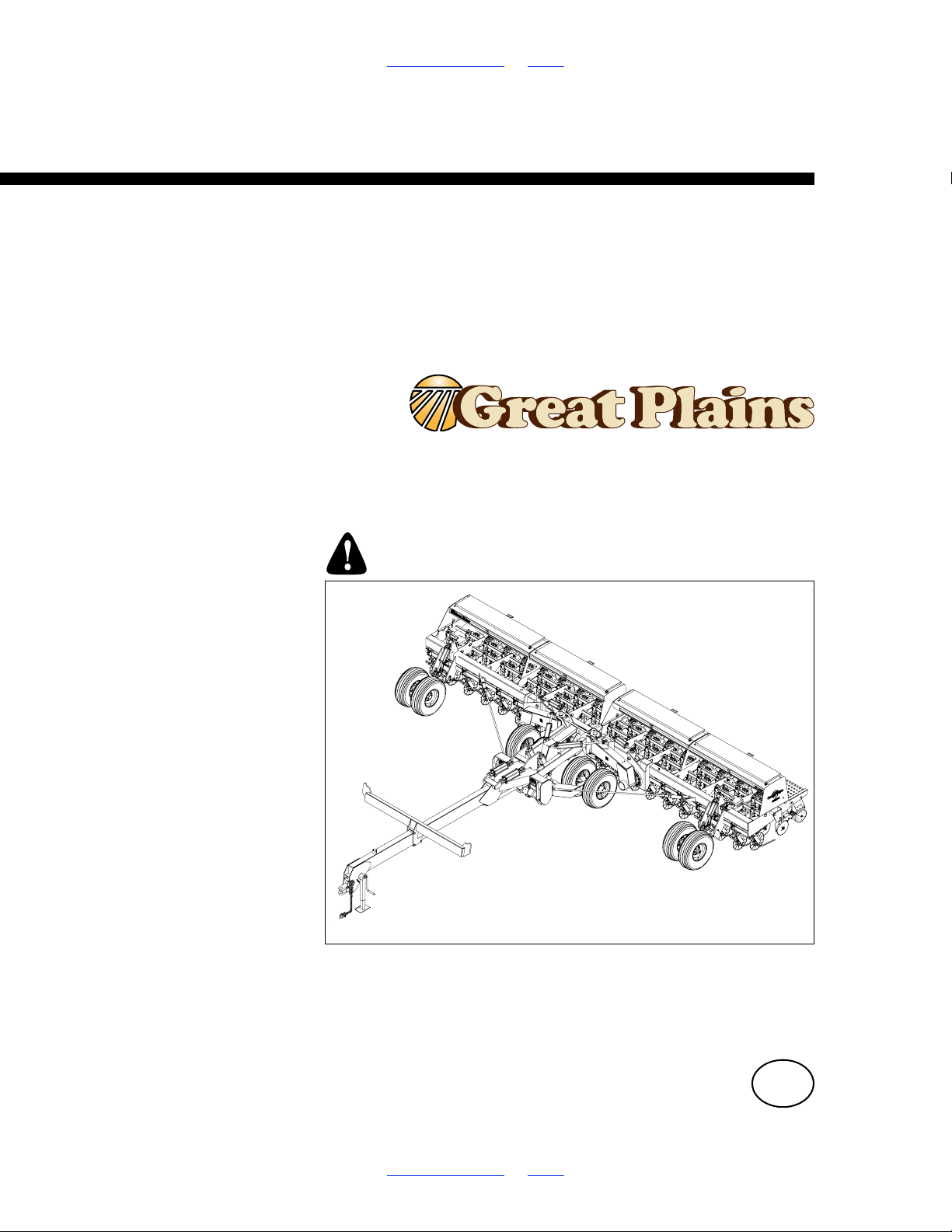
Table of Contents Index
14570
Operator Manual
2N-2410 and 2N-3010
Folding No-Till Drill
Manufacturing, Inc.
www.greatplainsmfg.com
Read the operator manual entirely. When you see this symbol, the
subsequent instructions and warnings are serious - follow without
exception. Your life and the lives of others depend on it!
Illustrations may show optional equipment not supplied with standard unit or
may depict similar models where a topic is identical.
ORIGINAL INSTRUCTIONS
© Copyright 1999 Printed 2018-08-02 196-126M
Table of Contents Index
EN
Page 2
Machine Identification
Record your machine details in the log below. If you replace this manual, be sure to transfer this information to the new
manual.
If you or the dealer have added options not originally ordered with the machine, or removed options that were originally
ordered, the weights and measurements are no longer accurate for your machine. Update the record by adding the
machine weight and measurements with the option(s) weight and measurements.
Model Number
Serial Number
Machine Height
Machine Length
Machine Width
Machine Weight
Year of Construction
Delivery Date
First Operation
Accessories
Dealer Contact Information
Name:
Street:
City/State:
Telephone:
Email:
Dealer’s Customer
No.:
WARNING:
Cancer and Reproductive Harm - www.P65Warnings.ca.gov
Page 3

2N-2410 & 2N-3010 Cover Index iii
Table of Contents
Important Safety Information.................................................1
Safety Decals ....................................................................5
INTRODUCTION ....................................................................13
Description of Unit ....................................................13
Intended Usage ........................................................13
Models Covered .......................................................13
Document Family .....................................................13
Using This Manual....................................................13
Owner Assistance ....................................................14
Further Assistance ...................................................14
Drill Preparation and Setup .................................................15
Pre-start Checklist ...........................................................15
Hitch Height Adjustment...........................................15
Installing Drill Control Consoles.......................................16
Bleeding Hydraulic Systems............................................17
Field-Lift Hydraulics..................................................17
Raise-To-Fold Hydraulics.........................................18
Fold Hydraulics.........................................................18
Marker Hydraulics ....................................................19
Frame Leveling Adjustment......................................20
Aligning Boxes..........................................................21
Operating Instructions .........................................................22
Pre-start Checklist ...........................................................22
Tractor Requirements......................................................22
Hitching Tractor to Drill.............................................23
Operating Control Console.......................................23
Operating Electric Clutch Consoles..........................24
Folding the Drill ........................................................24
Unfolding the Drill .....................................................25
Lifting the Drill in the Field........................................26
Field Operations .......................................................26
Opener Operation.....................................................27
Marker Operation .....................................................27
Shaft Monitor Operation ...........................................28
Electric Clutch Operation..........................................28
Acremeter Operation................................................28
Transporting .............................................................29
Parking .....................................................................29
Adjustments ..........................................................................30
No-Till Seeding.........................................................30
Coulter Adjustments.................................................30
Hydraulic Depth Control ...........................................31
Electric Clutch Switch Adjustment...................................32
Pull Cable Adjustments ............................................33
Weights ....................................................................33
Opener Down-Pressure Adjustment................................36
Press Wheel Adjustment .................................................36
Setting the Seeding Rate ................................................37
Gauge-Wheel Drive Adjustment...............................39
Disk Scraper Adjustment..........................................39
Leveling Adjustment.................................................39
Marker Adjustments .................................................40
Disk Adjustment .......................................................41
Coulter Tines............................................................42
Harrow Attachment Adjustment ...............................42
Seed-Lok..................................................................42
Troubleshooting ...................................................................43
General Maintenance ......................................................45
Cylinder Lock Channels ...........................................46
Storage.....................................................................46
Lubrication............................................................................47
Optional Attachments Lubrication ............................49
Options..................................................................................51
Coulter Tines............................................................51
Weight Brackets.......................................................51
Shaft Monitors ..........................................................51
Markers ....................................................................52
Small Seeds Attachment..........................................52
Harrow Attachment ..................................................53
Rear Mount Boom ....................................................53
Seed Box Agitator ....................................................53
Seed-Lok Firming Wheels........................................54
Seed-Cup Plugs .......................................................54
Specifications and Capacities.............................................55
Appendix ...............................................................................56
Electric Clutch Console and Wire Harness .....................56
Torque Values Chart for Common Bolt Sizes .................57
Tire Inflation Chart....................................................57
© Copyright 1999 All rights Reserved
Great Plains Manufacturing, Inc. provides this publication “as is” without warranty of any kind, either expressed or implied. While every precaution has been
taken in the preparation of this manual, Great Plains Manufacturing, Inc. assumes no responsibility for errors or omissions. Neither is any liability assumed for
damages resulting from the use of the information contained herein. Great Plains Manufacturing, Inc. reserves the right to revise and improve its products as
it sees fit. This publication describes the state of this product at the time of its publication, and may not reflect the product in the future.
Registered Trademarks of Great Plains Manufacturing, Inc. include: Air-Pro, Clear-Shot, Discovator, Great Plains, Land Pride, MeterCone,
Nutri-Pro, Seed-Lok, Solid Stand, Terra-Guard, Turbo-Chisel, Turbo-Chopper, Turbo-Max, Turbo-Till, Ultra-Till, Whirlfilter, and Yield-Pro.
Trademarks of Great Plains Manufacturing, Inc. include: AccuShot, Max-Chisel, Row-Pro,
Singulator Plus, Short Disk, Swath Command, Terra-Tine, Ultra-Chisel, and X-Press.
Brand and Product Names that appear and are owned by others are trademarks of their respective owners.
Printed in the United States of America
8/2/18 Cover Index 196-126M
Page 4
2N-2410 & 2N-3010 Table of Contents Index 1
Important Safety Information
Look for Safety Symbol
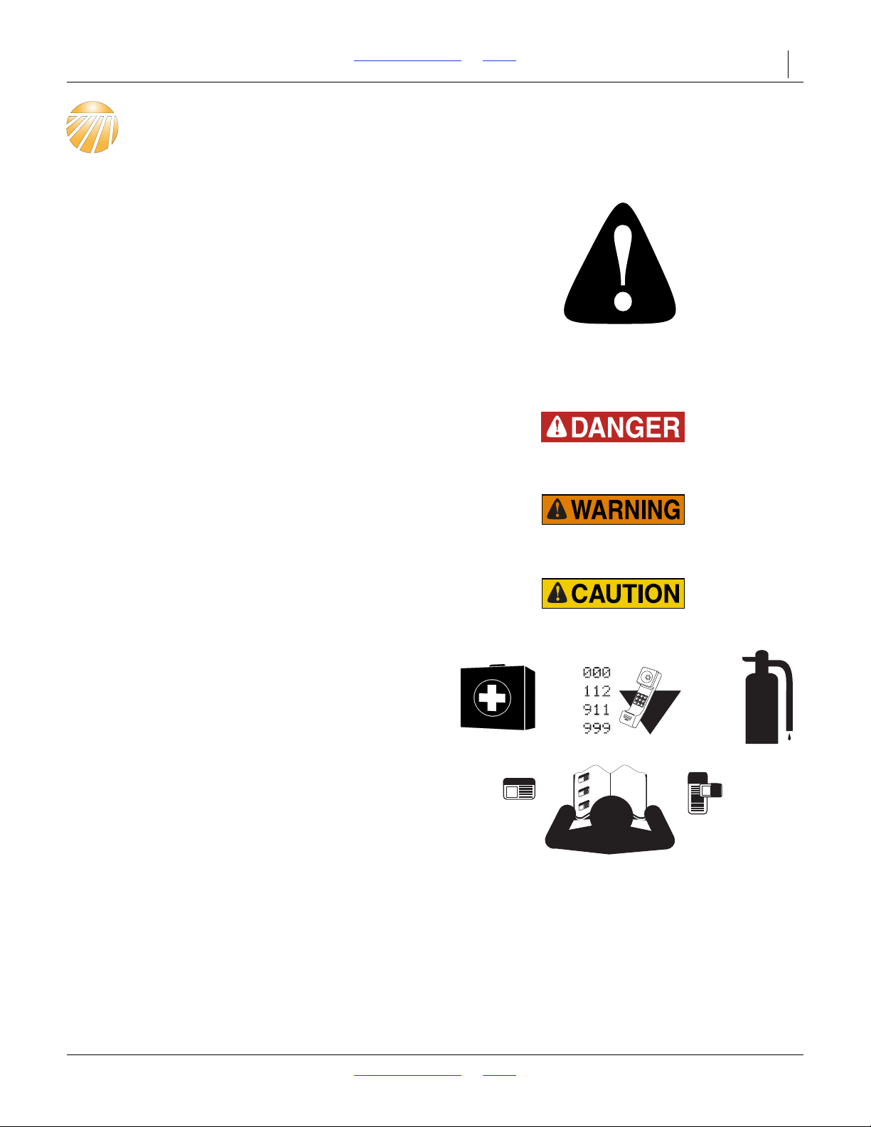
The SAFETY ALERT SYMBOL indicates there is a
potential hazard to personal safety involved and extra
safety precaution must be taken. When you see this
symbol, be alert and carefully read the message that
follows it. In addition to design and configuration of
equipment, hazard control and accident prevention are
dependent upon the awareness, concern, prudence and
proper training of personnel involved in the operation,
transport, maintenance and storage of equipment.
Be Aware of Signal Words
Signal words designate a degree or level of hazard
seriousness.
DANGER, and the color Safety Red, indicate an
imminent hazard which, if not avoided, will result in death
or serious injury. This signal word is limited to the most
extreme situations, typically for machine components
that, for functional purposes, cannot be guarded.
WARNING, and the color Safety Orange, indicate a
potential hazard which, if not avoided, could result in
death or serious injury, and includes hazards that are
exposed when guards are removed. It may also be used
to alert against unsafe practices.
CAUTION, and the color Safety Yellow, indicate a
potential hazard which, if not avoided, may result in
minor or moderate injury. It may also be used to alert
against unsafe practices.
Prepare for Emergencies
Be prepared if a fire starts
Keep a first aid kit and fire extinguisher handy.
Keep emergency numbers for doctor, ambulance, hospital
and fire department near phone.
Be Familiar with Safety Decals
Read and understand “Safety Decals” on page 5,
thoroughly.
Read all instructions noted on the decals.
Keep decals clean. Replace damaged, faded and illegible
decals.
8/2/18 Table of Contents Index 196-126M
Page 5

2N-2410 & 2N-3010 Table of Contents Index Important Safety Information 2
Wear Protective Equipment
Wear protective clothing and equipment.
Wear clothing and equipment appropriate for the job.
Avoid loose-fitting clothing.
Because prolonged exposure to loud noise can cause
hearing impairment or hearing loss, wear suitable
hearing protection such as earmuffs or earplugs.
Because operating equipment safely requires your full
attention, avoid wearing entertainment headphones while
operating machinery.
Handle Chemicals Properly
Agricultural chemicals can be dangerous. Improper use
can seriously injure persons, animals, plants, soil and
property.
Read and follow chemical manufacturer’s instructions.
Wear protective clothing.
Handle all chemicals with care.
Avoid inhaling smoke from any type of chemical fire.
Never drain, rinse or wash dispensers within 100 feet of a
freshwater source, nor at a car wash.
Store or dispose of unused chemicals as specified by
chemical manufacturer.
Dispose of empty chemical containers properly. Laws
generally require power rinsing or rinsing three times,
followed by perforation of the container to prevent re-use.
Avoid High Pressure Fluids
Escaping fluid under pressure can penetrate the skin,
causing serious injury.
Avoid the hazard by relieving pressure before
disconnecting hydraulic lines.
Use a piece of paper or cardboard, NOT BODY PARTS, to
check for suspected leaks.
Wear protective gloves and safety glasses or goggles when
working with hydraulic systems.
If an accident occurs, seek immediate medical attention
from a physician familiar with this type of injury.
8/2/18 Table of Contents Index 196-126M
Page 6
2N-2410 & 2N-3010 Table of Contents Index Important Safety Information 3
Use A Safety Chain
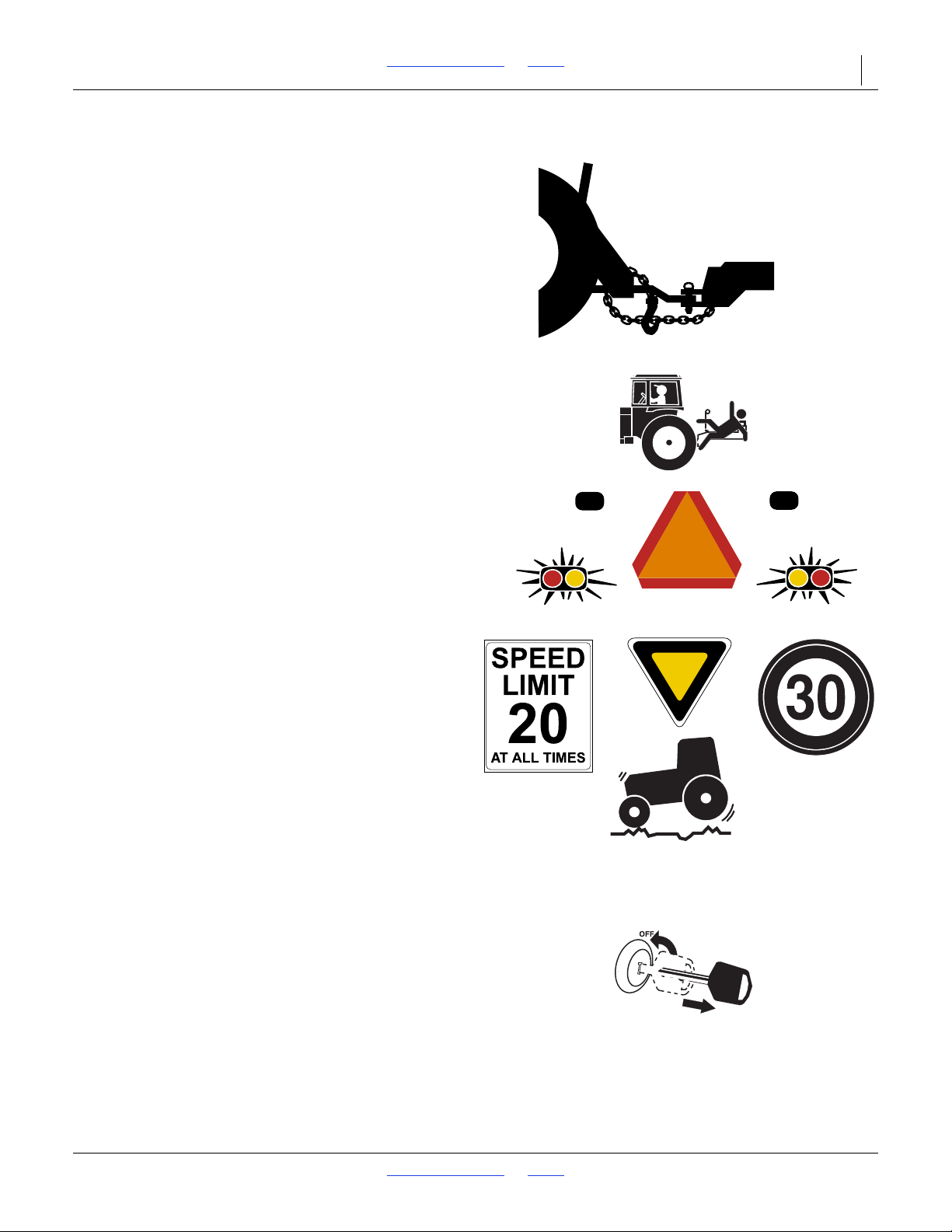
Use a safety chain to help control drawn machinery
should it separate from tractor drawbar.
Use a chain with a strength rating equal to or greater than
the gross weight of towed machinery.
Attach chain to tractor drawbar support or other specified
anchor location. Allow only enough slack in chain to
permit turning.
Replace chain if any links or end fittings are broken,
stretched or damaged.
Do not use safety chain for towing.
Keep Riders Off Machinery
Riders obstruct the operator’s view. Riders could be
struck by foreign objects or thrown from the machine.
Never allow children to operate equipment.
Keep all bystanders away from machine during operation.
Use Safety Lights and Devices
Slow-moving tractors and towed implements can create
a hazard when driven on public roads. They are difficult
to see, especially at night.
Use flashing warning lights and turn signals whenever
driving on public roads.
Use lights and devices provided with implement.
Transport Machinery Safely
Maximum transport speed for implement is 20 mph
(30 kph). Some rough terrains require a slower speed.
Sudden braking can cause a towed load to swerve and
upset.
Ensure towing vehicle weighs at least
implement weight.
Do not exceed 20 mph (30 kph). Never travel at a speed
which does not allow adequate control of steering and
stopping. Reduce speed if drill is not equipped with
brakes.
Comply with state and local laws.
Carry reflectors or flags to mark drill in case of
breakdown on the road.
2
/3 (67%) of gross
Shutdown and Storage
Park on level ground.
Unhitch and store the drill in an area where children
normally do not play.
8/2/18 Table of Contents Index 196-126M
Page 7
2N-2410 & 2N-3010 Table of Contents Index Important Safety Information 4
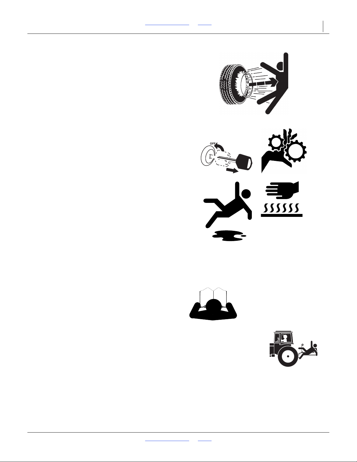
Tire Safety
Tire changing can be dangerous and should be
performed by trained personnel using correct tools and
equipment.
When inflating tires, use a clip-on chuck and extension
hose long enough for you to stand to one side–not in front
of or over tire assembly. Use a safety cage if available.
When removing and installing wheels, use wheel-handling
equipment adequate for weight involved.
Practice Safe Maintenance
Understand procedure before doing work. Use proper
tools and equipment. Refer to this manual.
Work in a clean, dry area.
Lower the drill, put tractor in park, turn off engine, and
remove key before performing maintenance. If work must
be performed with implement raised, use blocks or
jackstands rated for the drill weight.
Make sure all moving parts have stopped and all system
pressure is relieved.
Allow drill to cool completely.
Disconnect battery ground cable (-) before servicing or
adjusting electrical systems.
Welding: Disconnect battery ground. Avoid fumes from
heated paint.
Inspect all parts. Make sure parts are in good condition
and installed properly.
Remove buildup of grease, oil or debris.
Remove all tools and unused parts from drill before
operation.
Safety At All Times
Thoroughly read and understand the instructions in this
manual before operation. Read all instructions noted on
the safety decals.
Be familiar with all drill functions.
Operate machinery from the driver’s seat only.
Do not leave drill unattended with tractor engine running.
Do not stand between the moving tractor and drill during
hitching.
Keep hands, feet and clothing away from power-driven
parts.
Wear snug-fitting clothing to avoid entanglement with
moving parts.
Make sure all persons are clear of working area.
8/2/18 Table of Contents Index 196-126M
Page 8
2N-2410 & 2N-3010 Table of Contents Index Important Safety Information 5
12945A
Direction of travel
Main Frame
68478
Safety Decals
Safety Reflectors and Decals
Your implement comes equipped with all lights, safety
reflectors and decals in place. They were designed to
help you safely operate your implement.
Read and follow decal directions.
Keep lights in operating condition.
Keep all safety decals clean and legible.
Replace all damaged or missing decals. Order new decals
from your dealer. Refer to this section for proper decal
placement.
When ordering new parts or components, also request
corresponding safety decals.
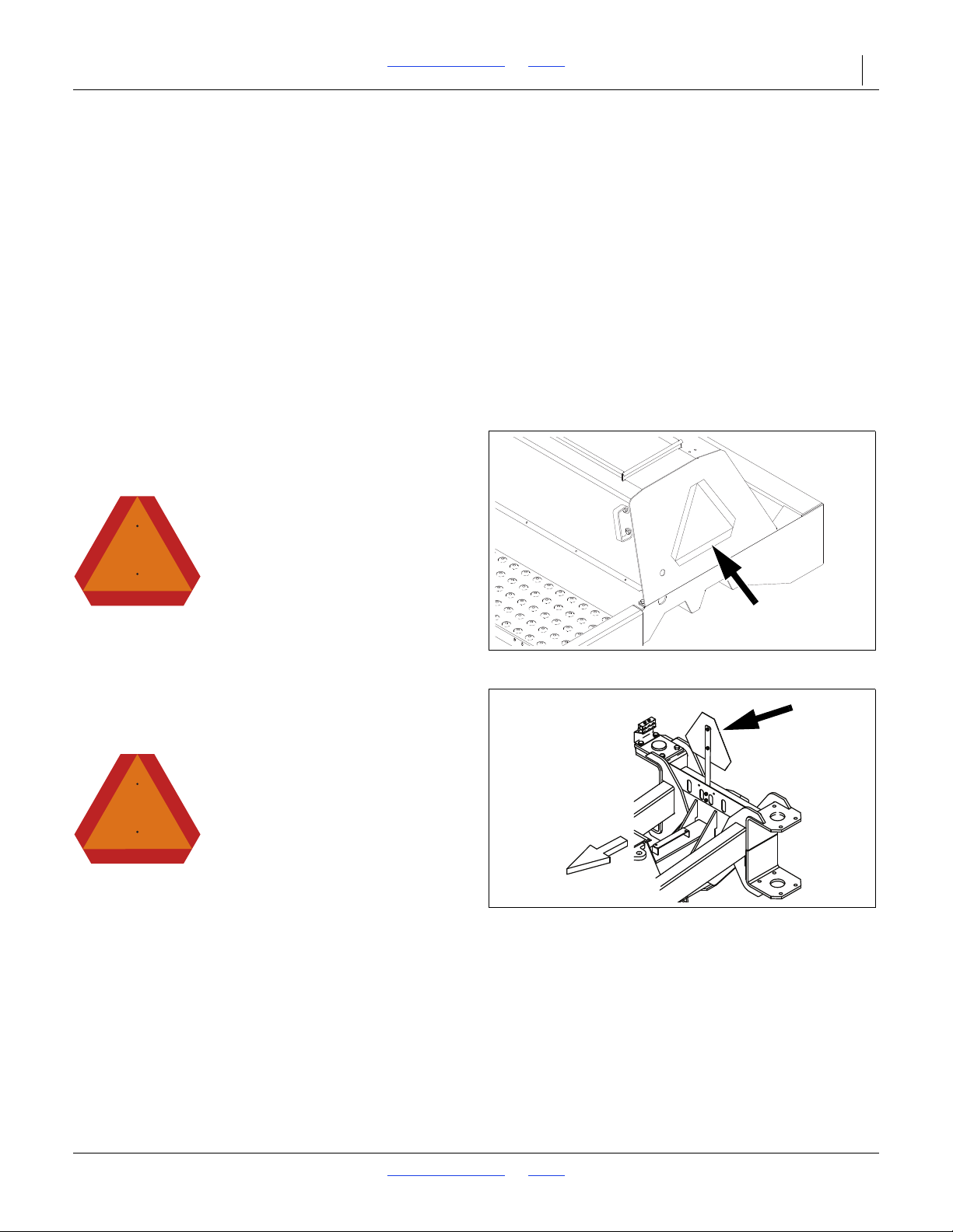
Reflector: Slow Moving Vehicle (SMV)
(2N-2410 S/N C1977-)(2N-3010 S/N D2485-)
818-055C
To install new decals:
1. Clean the area on which the decal is to be placed.
2. Peel backing from decal. Press firmly on surface,
being careful not to cause air bubbles under decal.
At rear of drill when folded
1 total
Reflector: Slow Moving Vehicle (SMV)
(2N-2410 S/N C1978+)(2N-3010 S/N D2486+)
818-055C
At rear of mainframe.
1 total
8/2/18 Table of Contents Index 196-126M
Page 9
2N-2410 & 2N-3010 Table of Contents Index Important Safety Information 6
68479
00000
68479A
68479A
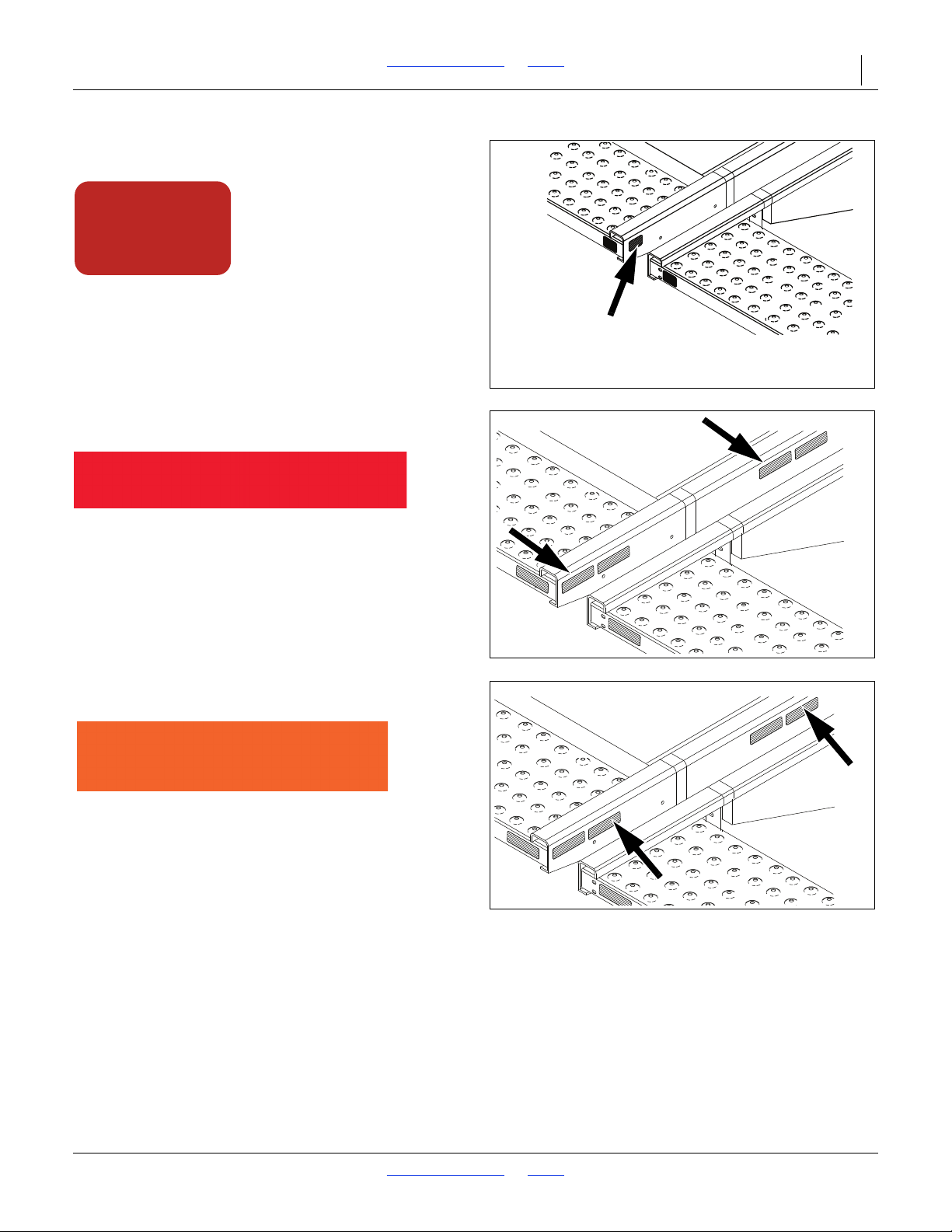
Reflectors: Red
818-230C
On side frames at inner ends of walkboard
2 total
Reflectors: Red
838-266C
On side frames at inner ends of walkboard
4 total
Reflectors: Daytime
838-267C
On side frames at inner ends of walkboard;
4 total
8/2/18 Table of Contents Index 196-126M
Page 10
2N-2410 & 2N-3010 Table of Contents Index Important Safety Information 7
12943A
68479A
68479A
68479A
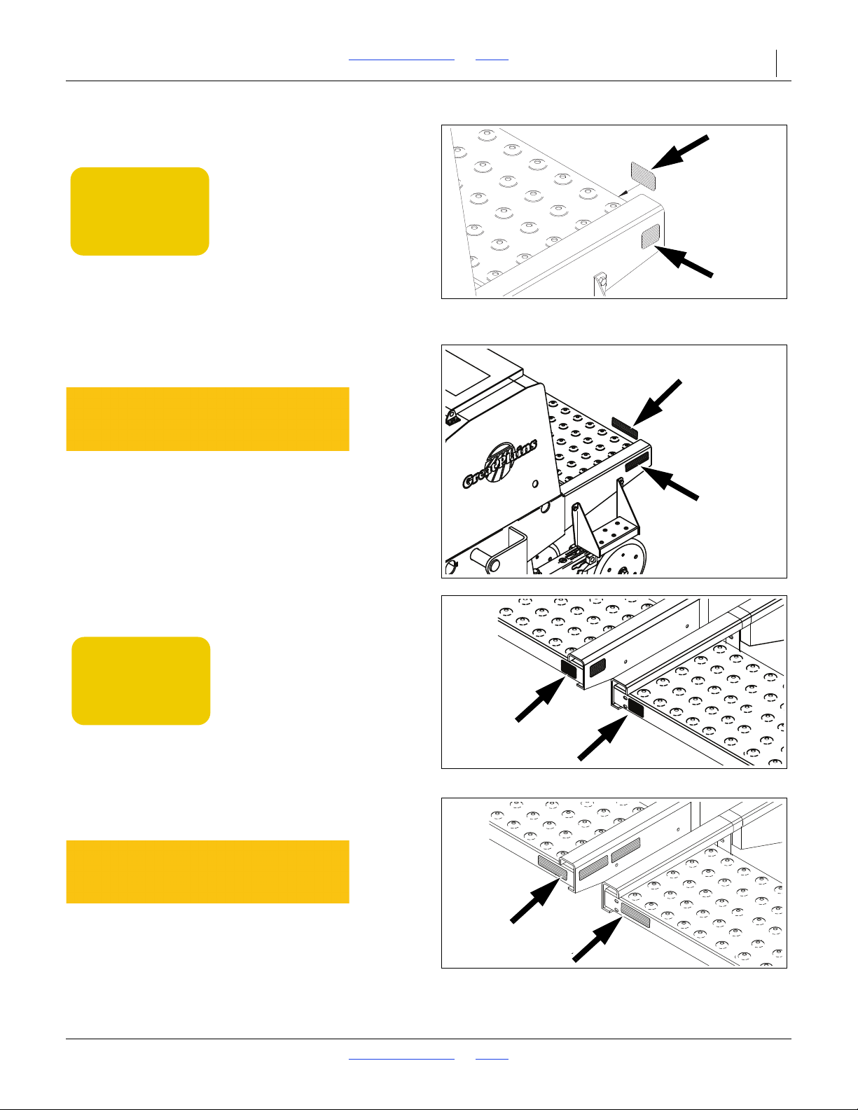
Reflectors: Amber
818-229C
On rear of walkboards at outer ends;
On side frames at outer ends of walkboard;
4 total
Reflectors: Amber
838-265C
On rear of walkboards at outer ends;
On side frames at outer ends of walkboard;
4 total
Reflectors: Amber
818-229C
On rear of walkboards at inner ends;
2 total
Reflectors: Amber
838-265C
On rear of walkboards at inner ends;
2 total
8/2/18 Table of Contents Index 196-126M
Page 11
2N-2410 & 2N-3010 Table of Contents Index Important Safety Information 8
13734
12941A
14526
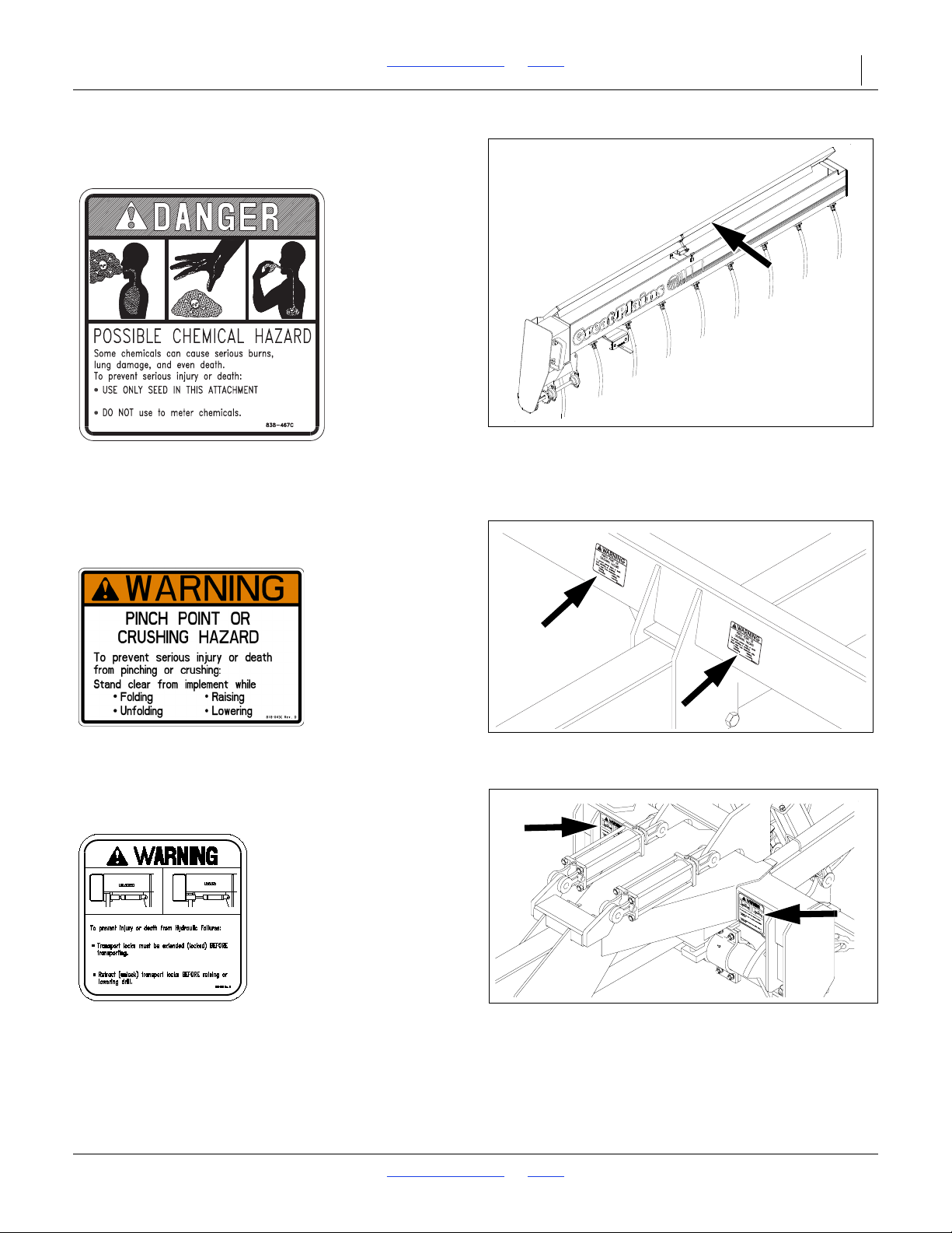
Danger: Chemical Hazard
838-467C
Inside drill box;
1 total
Warning: Pinching/Crushing
818-045C
2 total
Warning: Transport Lock
818-477C
2 total
8/2/18 Table of Contents Index 196-126M
Page 12
2N-2410 & 2N-3010 Table of Contents Index Important Safety Information 9
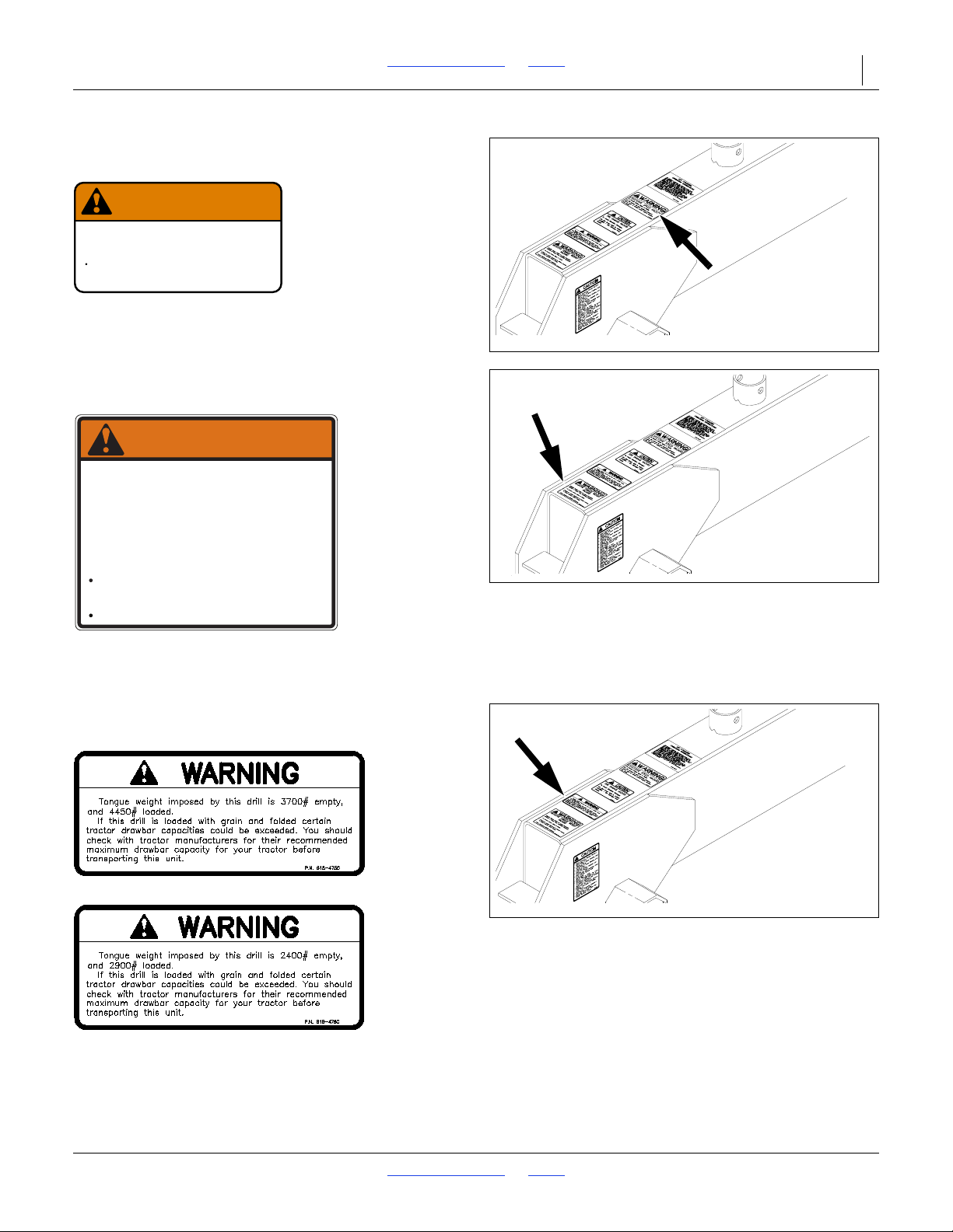
12950
818-188C Rev. C
Do Not exceed 20 mph maximum transport
speed. Loss of vehicle control and/or machine
can result.
To Prevent Serious Injury or Death:
EXCESSIVE SPEED HAZARD
WARNING
12950
NEGATIVE TONGUE WEIGHT
HAZARD
Negative tongue weight can cause immediate
elevation of tongue when unhitching implement
To prevent serious injury or death:
Always be certain implement is hitched securely
to tractor drawbar before reaising.
Lower implement BEFORE unhitching.
818-019C Rev. D
WARNING
12950
Warning: Speed
818-188C
On tongue tube near hitch
1 total
Warning: Negative Tongue Weight
818-019C
On tongue tube near hitch;
1 total
Warning: 30-Ft./24-Ft. Tongue Weight
818-475C (3010)/
818-476C (2410)
On tongue tube near hitch;
1 total
8/2/18 Table of Contents Index 196-126M
Page 13

2N-2410 & 2N-3010 Table of Contents Index Important Safety Information 10
12944A
818-020C Rev. B
Do Not lower drill in folded
position - tire damage may
result.
To Avoid Machine Damage:
TIRE DAMAGE HAZARD
CAUTION
12944A
WARNING:
Cancer and Reproductive Harm - www.P65Warnings.ca.gov
Read Owner’s Manual before using machine.
Stand clear when folding and unfolding markers.
Stand clear when raising and lowering machine.
Keep all safety shields and devices in place.
Keep hands, feet, and clothing away from
Never ride on machine.
Always lower or properly support machine
Escaping hydraulic fluid can cause serious
Review safety instructions with all operators
moving chains and sprockets.
BEFORE servicing.
818-587C Rev. B
injury.
annually.
CAUTION
13317A
Caution: Lowering Drill
818-020C
On tongue tube near hitch
1 total
General Caution
818-587C
On tongue tube near hitch;
1 total
Caution: Tires Not A Step
818-398C
On side frames above tires;
2 total
8/2/18 Table of Contents Index 196-126M
Page 14
2N-2410 & 2N-3010 Table of Contents Index Important Safety Information 11
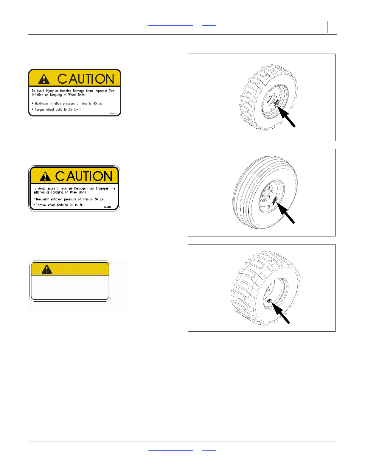
68481
CAUTION
To Avoid Injury or Machine Damage from Improper Tire
Inflation or Torquing of Wheel Bolts:
•
Maximum inflation pressure of tires is 60 psi.
•
Torque wheel bolts to 105 lb-ft.
838-426C
Caution: Tire Pressure and Torque
838-092C
Gauge wheel with 265/70B16.5 NHS skid steer tire;
4 total
Caution: Tire Pressure and Torque
818-855C
Gauge wheel with 11L-15 X 8 PLY ribbed tire;
4 total
Caution: Tire Pressure and Torque
838-426C
Gauge wheel with 395/55B16.5 NHS skid steer tire;
Transport wheel with 395/55B16.5 NHS skid steer tire;
4 total
8/2/18 Table of Contents Index 196-126M
Page 15
2N-2410 & 2N-3010 Table of Contents Index Important Safety Information 12
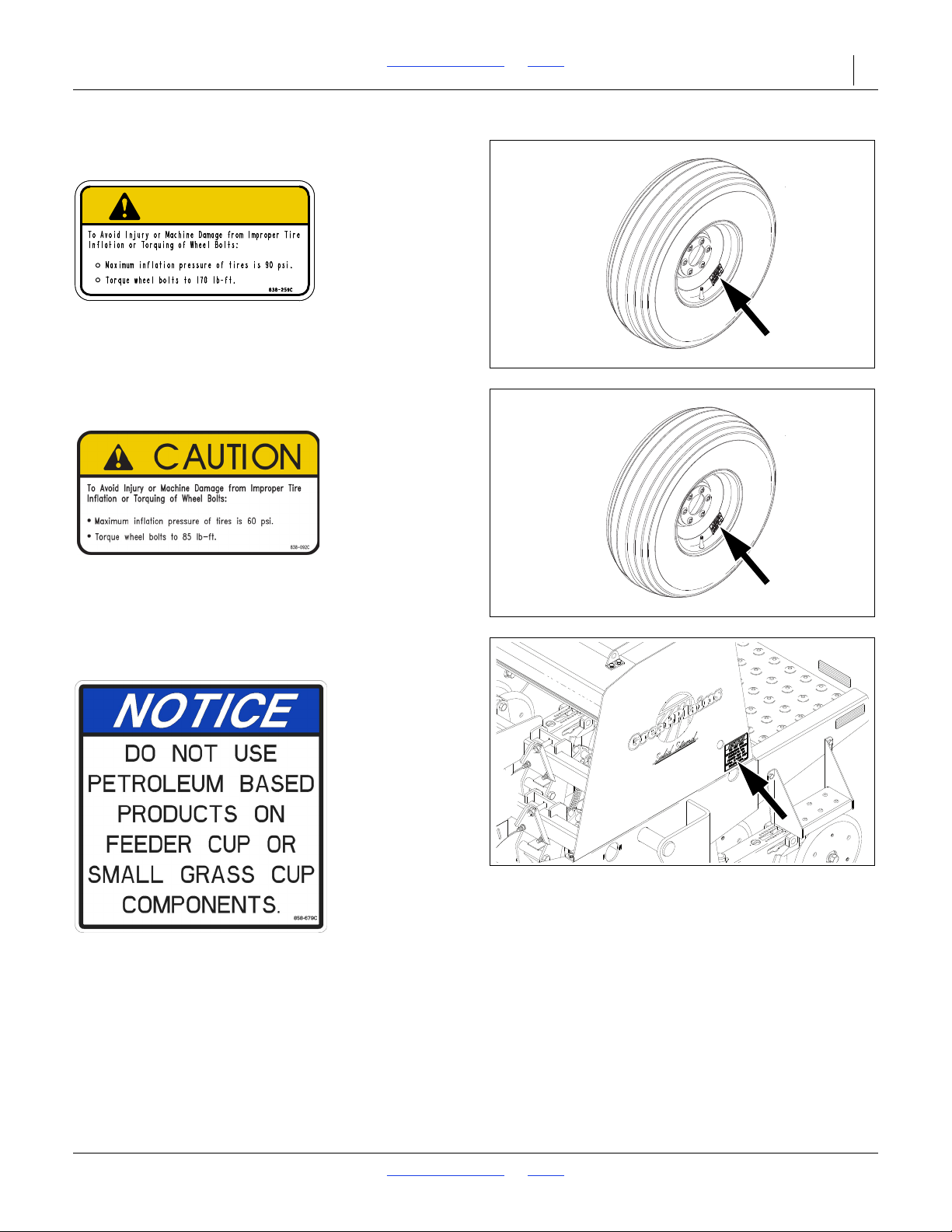
68481
CAUTION
68481
2N-2410
68668
Caution: Tire Pressure and Torque
838-259C
Transport wheel with 12.5-15 20 ply ribbed tire;
4 total
Caution: Tire Pressure and Torque
838-092C
Auxiliary axle;
4 total
NOTICE: No Petroleum Products
858-679C
Small seed option;
2 to 4 total
8/2/18 Table of Contents Index 196-126M
Page 16
2N-2410 & 2N-3010 Table of Contents Index 13
14570
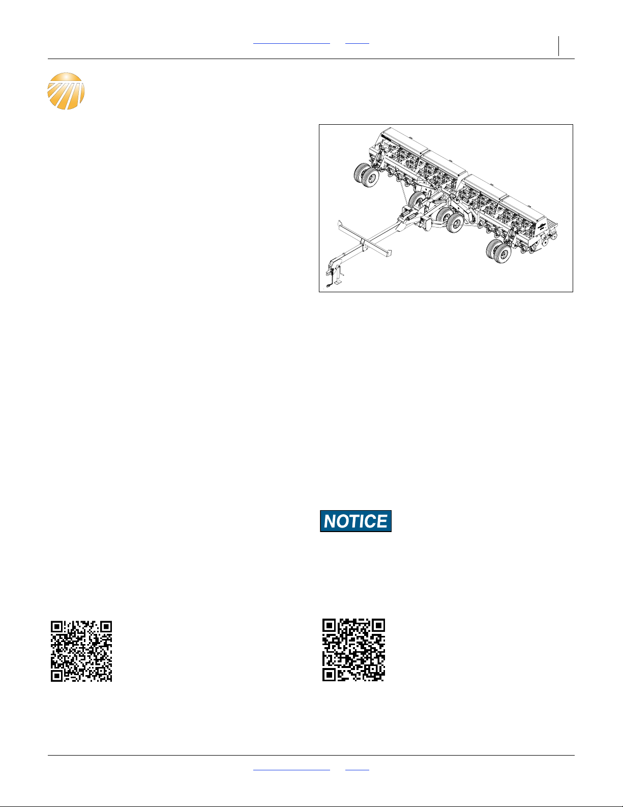
Figure 1
2N-2410 Drill
Dealer QRC
The QR Code (Quick Response) to the
left will take you to available dealers for
Great Plains products. Refer to the
Parts Manual QR Locater for detailed
instructions.
Manual Family QRC
The QR Code (Quick Response) to the
left will take you to this machine’s family
of manuals. Use your smart phone or
tablet to scan the QR Code with an
appropriate App to begin viewing.
INTRODUCTION
Great Plains welcomes you to its growing family of new
product owners. This implement has been designed
with care and built by skilled workers using quality
materials. Proper assembly, maintenance and safe
operating practices will help you get years of
satisfactory use from the machine.
Description of Unit
The two-section folding no-till drill is a towed seeding
implement for no- or minimum-till soil conditions. The
drill is equipped with two hydraulic circuits. One is used
to raise and lower the drill for field operations. A
separate electro-hydraulic circuit lifts, locks and folds
the implement for transport. An in-cab control console
allows the operator to switch between functions on the
electro-hydraulic circuit. The drill is outfitted with
coulters and double-disk openers. The openers are
mounted on parallel arms. Press wheels follow the
opener disks to firm the seedbed and control seeding
depth.
Intended Usage
This machine is intended for use in minimum- or no-till
applications.
Models Covered
2N-2410-281028 row, 10-inch spacing
2N-2410-360836 row, 8-inch spacing
2N-2410-387538 row, 7.5-inch spacing
2N-3010-361036 row, 10-inch spacing
2N-3010-440844 row, 8-inch spacing
2N-3010-487548 row, 7.5-inch spacing
Document Family
196-126M - 2N-2410 and 2N-3010 Operator Manual
(this document)
196-126B - Seed Rate Chart
196-126P - Parts Manual
Using This Manual
This manual will familiarize you with safety, assembly,
operation, adjustment, troubleshooting and
maintenance. Read this manual and follow the
recommendations to help ensure safe and efficient
operation.
This manual is current at printing. Some parts may
change to assure top performance.
Definitions
Right and left as used in this manual are determined by
facing the direction the machine will travel while in use
unless otherwise stated.
A crucial point of information related to the preceding topic.
For safe and correct operation, read and follow the directions
provided before continuing.
NOTE: Useful information related to the preceding
topic.
8/2/18 Table of Contents Index 196-126M
Page 17
2N-2410 & 2N-3010 Table of Contents Index INTRODUCTION 14
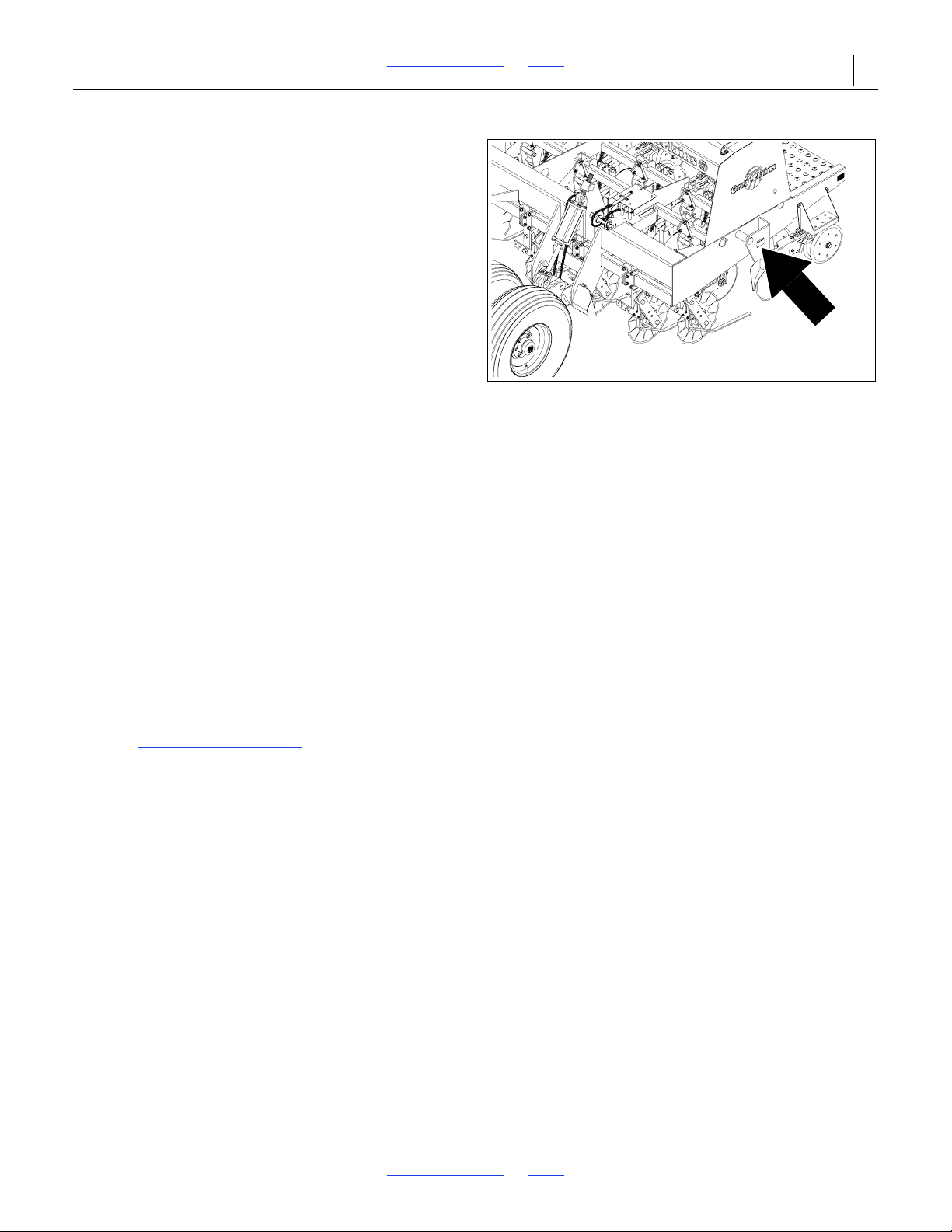
16537
Figure 2
Serial Number Plate
Owner Assistance
If customer service or repair parts are needed contact
your Great Plains dealer. They have trained personnel,
parts and service equipment specially designed for
Great Plains products.
Your machine’s parts were specially designed and
should only be replaced with Great Plains parts. Always
use the serial and model number when ordering parts
from your Great Plains dealer. The serial number plate is
located on the outside end of the left drill box as shown in
Figure 2.
Further Assistance
Great Plains Manufacturing, Inc. and your Great Plains
dealer want you to be satisfied with your new product. If
for any reason you do not understand any part of this
manual or are otherwise dissatisfied, please take the
following actions first:
1. Discuss the matter with your dealership service
manager. Make sure they are aware of any problems
so they can assist you.
2. If you are still unsatisfied, seek out the owner or
general manager of the dealership.
If your dealer is unable to resolve the problem or the
issue is parts related, please contact:
Great Plains Service Department
1525 E. North St.
P.O. Box 5060
Salina, KS 67402-5060
Or go to www.greatplainsag.com
information at the bottom of your screen for our service
department.
and follow the contact
8/2/18 Table of Contents Index 196-126M
Page 18
2N-2410 & 2N-3010 Table of Contents Index 15
16273
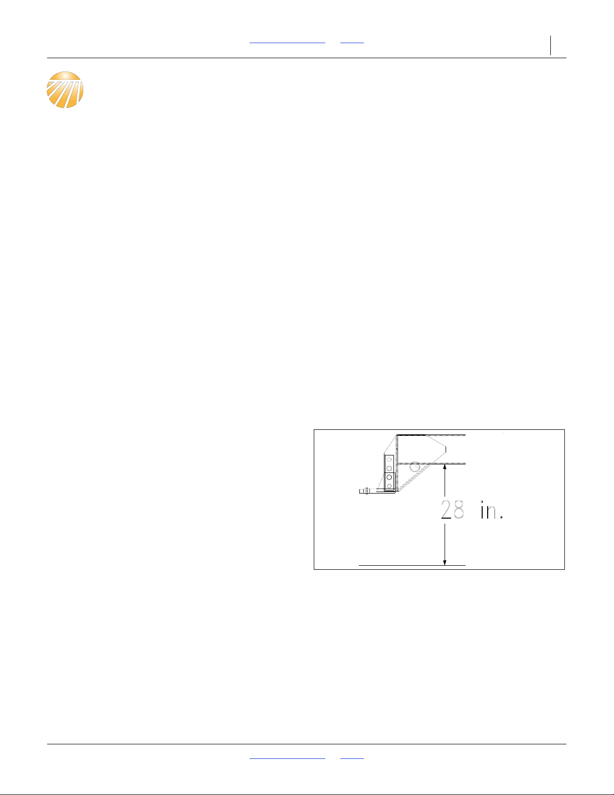
Figure 3
Tongue Height
Drill Preparation and Setup
This section will help you prepare your tractor and drill for
use. The drill hitch must be adjusted to match drawbar
height, and the drill control console must be installed in
your tractor.
This section also covers bleeding the drill hydraulics and
making drill frame and box adjustments. As the operator,
you may need to perform these functions after dill repair.
Before operating the drill, check that the hydraulic
systems are free or air, the frame is level, and boxes are
aligned.
Pre-start Checklist
1. Read and understand “Important Safety
Information,” page 1.
2. Check that all working parts are moving freely, bolts
are tight, and cotter pins are spread.
3. Check that all grease fittings are in place and
lubricated. Refer to Lubrication, page 47.
4. Check that all safety labels and reflectors are
correctly located and legible. Replace if damaged.
See Safety Decals, page 5.
5. Inflate tires to pressure recommended and tighten
wheel bolts as specified. See Tire Inflation Chart
page 57.
Hitch Height Adjustment
Refer to Figure 3
For proper operation, the drill tongue must run parallel
to the ground in field position. Follow these instructions
to adjust the drill hitch to match your tractor drawbar
height.
1. Check the distance from under the tongue to the
ground as shown in Figure 3. Using the drill jack,
adjust the tongue up or down until the distance is
about 28 inches
2. Back the tractor drawbar up to the drill hitch.
Determine how much adjustment is needed for the
drill to match drawbar height.
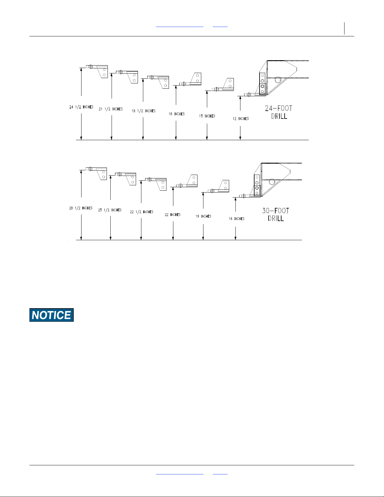
3. Unbolt the hitch from the tongue. Bolt the hitch so
the drill matches drawbar height. Keeping in mind
your drill size, refer to Figure 4 or Figure 5 for the
different ways you can bolt the hitch and the
resulting hitch heights.
.
8/2/18 Table of Contents Index 196-126M
Page 19
2N-2410 & 2N-3010 Table of Contents Index Drill Preparation and Setup 16
Hitch Height Adjustment, 24-Foot Drills
Figure 4
16274
Hitch Height Adjustment, 30-Foot Drills
Figure 5
16532
4. Hitch the drill to the tractor using a hitch pin at least
one inch in diameter. Install a retaining clip on the
hitch pin to prevent it from working up.
A clevis-style hitch, Great Plains part number
196-136H, is available through your Great Plains
dealer.
When hitching the drill to a different tractor, check for
differences in drawbar heights and re-adjust the drill hitch
accordingly.
Installing Drill Control Consoles
1. Mount the control boxes at a convenient location in
the tractor cab. Connect the 12-foot extension cable
to the pin connector on the back of the control box.
Route the cable to the tractor drawbar area. Secure
the cable to avoid damage.
2. Connect the power cords to a 12-volt power source
on the tractor. The polarity of the power supply is
very important. The red wire must be connected to
the positive (+) battery terminal. The white wire must
be connected to the negative (-) battery terminal.
To help with console and wire harness installation
refer to diagram on page 56.
8/2/18 Table of Contents Index 196-126M
Page 20

2N-2410 & 2N-3010 Table of Contents Index Drill Preparation and Setup 17
Bleeding Hydraulic Systems
A hydraulic system with air in the circuit will move in
jerky, uneven motions. If your hydraulics have not been
properly bled or you replace a hydraulic component,
bleed the hydraulics.
Field-Lift Hydraulics
The field-lift system is equipped with four rephasing-type
hydraulic cylinders that require a special procedure for
bleeding air. Read and follow the procedure carefully. Air
in the system will cause uneven seeding across the drill.
Do not loosen hose fittings in order to bleed air from this
system.
Escaping fluid under pressure can have sufficient pressure to
penetrate the skin causing serious injury. Avoid the hazard by
relieving pressure before disconnecting hydraulic lines. Use a
piece of paper or cardboard, NOT BODY PARTS, to check for
leaks. Wear protective gloves and safety glasses or goggles
when working with hydraulic systems. If an accident occurs,
see a doctor immediately.
This drill has a negative tongue weight when unfolded and
raised. Be certain that the drill is hitched securely to your
tractor drawbar and the hitch safety chain is securely attached
to the drill.
Never allow anyone under the drill when fittings are opened.
Escaping fluid may allow the drill to drop suddenly.
1. Check that the tractor reservoir is filled to the proper
level. It will take 4 gallons to charge the field-lift
cylinders.
2. Put the tractor in park and set the parking brake. If
your tractor does not have these features, block
wheels to prevent tractor from rolling.
3. Raise and support the main frame and outside ends
of boxes just high enough to take the weight off all
four field-lift cylinders.
4. With the drill blocked and supported, unpin both
ends of all four field-lift cylinders. The field-lift
cylinders are located on the wing gauge wheels and
the main-frame transport wheels. Remove and safely
position the cylinders so the rod ends are higher than
the base ends. Check that there is enough room for
the cylinder rods to fully extend without contacting
anything.
To prevent trapped air pockets, the rod end must be higher
than any other part of the cylinder.
5. With the tractor at idle, engage the lift-hydraulics
lever. When the cylinders for both gauge wheels
have completely extended, hold the lever on for one
minute.
6. Retract the cylinder rods. Extend the rods again and
hold the lever on for one more minute. Repeat this
step two more times to completely bleed the system.
7. Retract and reattach the hydraulic cylinders.
8. Recheck the tractor hydraulic reservoir level and add
clean fluid as necessary.
Transport-Lock Hydraulics
The transport-lock cylinders are not rephasing. The two
transport-lock cylinders are on each side of the main
frame above the transport axle pivot tubes. Follow these
steps to properly bleed the transport-lock hydraulics.
1. Check that the tractor reservoir is filled to the proper
level. It will take about one gallon to charge the
transport-lock cylinders.
2. Raise the drill to field position and support the main
frame.
3. Select the locks system on the control console.
Retract the lock cylinders completely.
4. Loosen the connection between the hose and baseend tee fitting on the left lock cylinder. With the
tractor at idle slowly work the remote lever to feed oil
to the base end of the lock cylinders. Stop when you
see oil coming from around the fitting. Do not attempt
to fully extend the lock cylinders when bleeding the
base ends.
5. With the cylinders completely extended, repeat step
4 for the rod-end fitting.
6. Recheck the tractor reservoir and add clean fluid as
necessary.
7. Retract and extend the lock cylinders several times
to expel most air from the system. The remaining air
will be expelled gradually during day-to-day
operations.
8. Recheck the tractor hydraulic reservoir and add
clean fluid as necessary.
8/2/18 Table of Contents Index 196-126M
Page 21

2N-2410 & 2N-3010 Table of Contents Index Drill Preparation and Setup 18
Raise-To-Fold Hydraulics
The raise-to-fold cylinders are double acting but not
rephasing. There are four cylinders in the raise-to-fold
system. Two are on the tool bar, and two are on the
tongue. Follow these steps to properly bleed the raise-tofold hydraulics.
1. Check that the tractor reservoir is filled to the proper
level. It will take 3.4 gallons to charge the raise-tofold cylinders.
2. Select the raise-to-fold system on the control
console.
3. Check that the drill is unfolded and resting safely on
the ground.
4. Disconnect the rod-end clevis of both tool-bar
cylinders and both tongue cylinders. Support the
cylinders so the rods may extend and retract freely.
5. Retract the tongue cylinders completely. This will
also fully extend the tool-bar cylinders.
6. Loosen the hose-end fitting coming into the tee on
the base end of the left tongue cylinder.
Do not attempt to bleed an O-ring fitting or O-ring damage
may occur.
7. Slowly work the remote lever to feed oil to the base
end of the tongue cylinders. Stop when you see oil
coming from around the fitting. Do not attempt to
extend the tongue cylinders while bleeding the base
ends.
8. Loosen the hose-end fittings at the tee on rod ends
of the tool-bar cylinders. Slowly work lever which
feeds oil to the rod end of the tool-bar cylinders. Stop
when you see oil coming from around the fittings. Do
not attempt to retract the tool-bar cylinders while
bleeding the rod ends.
9. Fully extend the tongue cylinders and retract the
tool-bar cylinders.
10. Loosen the hose-end fitting at the tee on the rod end
of the left tongue cylinder.
Do not attempt to bleed an O-ring fitting or O-ring damage
may occur.
11. Slowly work the lever in the opposite direction to feed
oil to rod end of the tongue cylinders. Stop when you
see oil coming from around the fitting. Do not attempt
to retract the tongue cylinders while bleeding the rod
ends.
12. Loosen the hose-end fittings at the tee coming from
the base ends of the tool-bar cylinders. Slowly work
the lever to feed oil to the base end of the tool-bar
cylinders. Stop when you see oil coming from around
the fittings. Do not attempt to extend the tool-bar
cylinders while bleeding the base ends.
13. Extend and retract the cylinders several times to
expel most air from the system. The remaining air
will gradually be pushed to the tractor during day-today operations.
14. Re-pin the tongue and tool-bar cylinders. Raise and
lower the wings several times to check for proper
operation. If movement is erratic, repeat bleeding
operation.
15. Recheck the tractor hydraulic reservoir level and add
clean fluid as necessary.
Fold Hydraulics
The fold cylinders are not rephasing. The two fold
cylinders connect the main frame and drill boxes. Follow
these steps to properly bleed the fold hydraulics.
Check that the transport-lock and raise-to-fold systems are
bled and completely operational before working with the fold
hydraulics.
1. Make sure the tractor hydraulic fluid reservoir is filled
to the proper level. It will take about two gallons to
charge the fold cylinders.
2. With the boxes unfolded unpin the rod-end clevis and
support the fold cylinders so they can be extended
and retracted.
3. Select the fold system on the control console.
Retract the fold cylinders completely.
4. Loosen the connection between the hose-end and
base-end tee fitting on the left fold cylinder.
5. With the tractor at idle slowly work the tractor lever to
feed oil to the base end of the fold cylinders. Stop
when you see oil coming from around the fitting. Do
not attempt to extend the fold cylinders when
bleeding base ends.
6. With cylinders completely extended, repeat the
procedure for the hose connection at the rod end.
7. Retract and extend the cylinders several times to
expel most air from this system. The remaining air
will gradually be pushed to the tractor during day-today operations.
8. Recheck the tractor reservoir level and add clean
fluid as necessary.
8/2/18 Table of Contents Index 196-126M
Page 22

2N-2410 & 2N-3010 Table of Contents Index Drill Preparation and Setup 19
Marker Hydraulics
Never allow anyone near the drill when cycling the markers.
1. Make sure the tractor hydraulic fluid reservoir is filled
to the proper level. It will take one gallon to charge
the dual marker cylinders.
2. With the drill unfolded and lowered, turn marker
switch on the control console to the left marker
position.
3. With the marker unfolded, crack the hydraulic hose
fitting located at the base end of the left marker
cylinder.
4. With the tractor at idle slowly work the tractor remote
lever to feed oil to the base end. Stop when you see
oil coming out around the hose ends. Tighten the
hose-end fittings.
5. Repeat step 3 and 4 for the hose-end fitting at the
rod end of the cylinder.
6. If dual markers are used, repeat steps 2, 3 and 4 for
the right marker cylinder.
Leave the control console switch in the left marker position
when bleeding the right marker cylinder. Both markers are
controlled by the left marker switch if your markers have a
sequence valve.
7. Fold and unfold the marker slowly to work all the air
out of your marker hydraulics.
JIC fittings do not require high torque. JIC and O-ring fittings
do not require sealant. Always use liquid pipe sealant when
adding or replacing pipe thread fittings. To avoid possible
danger of cracking hydraulic fittings from over tightening, do
not use plastic sealant tape.
8/2/18 Table of Contents Index 196-126M
Page 23
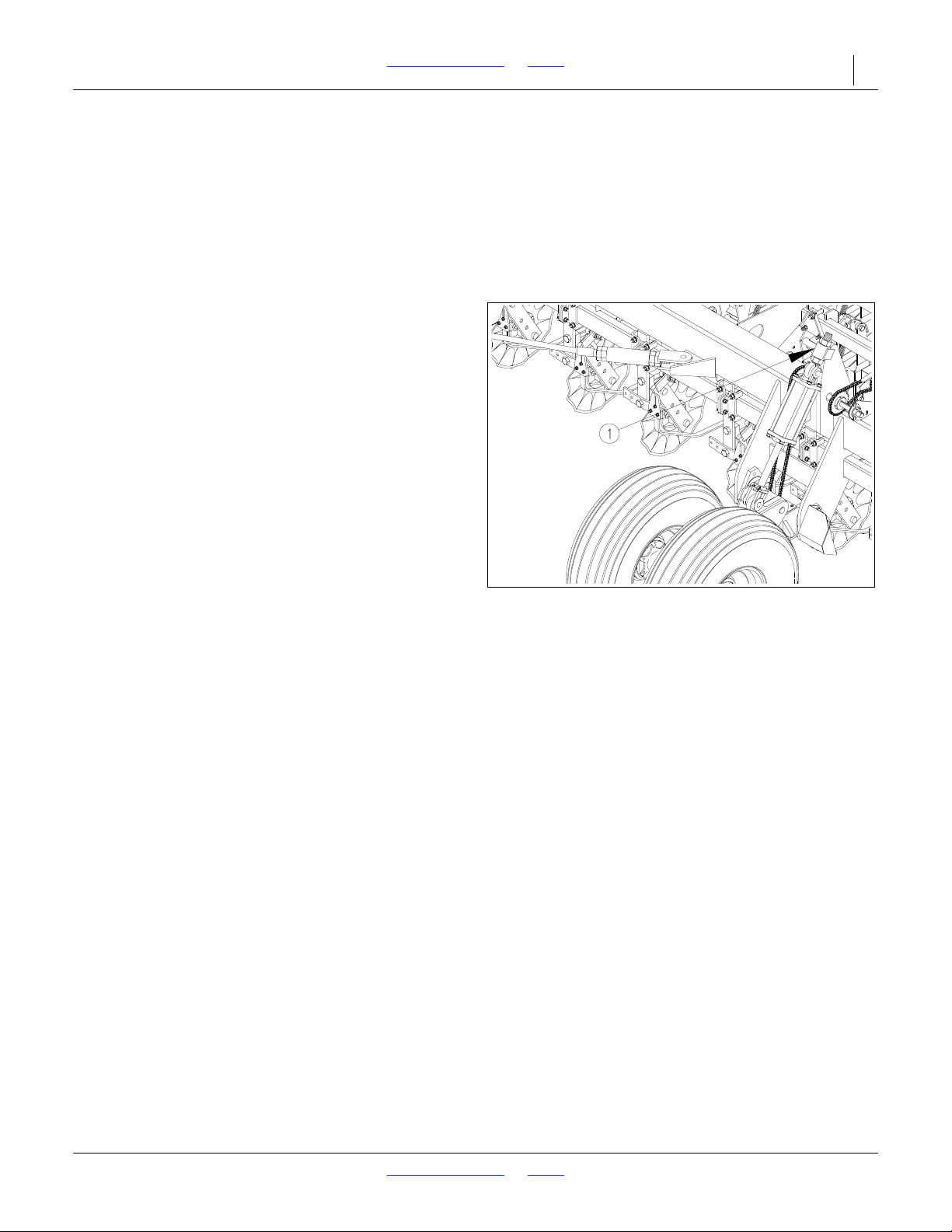
2N-2410 & 2N-3010 Table of Contents Index Drill Preparation and Setup 20
12779
Figure 6
Wing Gauge Wheel Eye-Bolt Adjustment
Frame Leveling Adjustment
Periodic frame leveling should not be necessary, but if
you are having trouble maintaining equal coulter depth
across the drill, check that the frame is level. When the
drill is level, the box frames will be the same distance
from the ground at both ends of the drill.
Complete the steps under Bleed the Fold Hydraulics,
page 18, before proceeding.
Refer to Figure 6
1. Locate the threaded eye bolt at the base end of the
gauge-wheel cylinders (1). The eye bolt is locked in
place by a jam nuts. Observe the amount of thread
exposed above the upper nut and below the lower
nut. If the exposed threads are roughly equal, no
initial adjustment is needed. Go to step 3.
2. If the exposed threads above and below the nuts are
not equal, loosen and adjust the jam nuts until the
exposed threads are within 3/8 inch of each other.
Repeat for other end of drill.
3. Move the drill to a level area. With the drill unfolded,
check that the tool-bar cylinders are completely
extended. Raise the drill to its highest position with
the field-lift cylinders. With the tractor idling, rephase
the cylinders by holding the hydraulic lever on for an
additional 30 seconds. Immediately lower the boxes
until the coulters and openers are just ready to touch
the ground.
4. Move the gauge-wheel eye bolts (1) in or out until the
frames are level. When the frames are level, the
openers on the outside end of the drill will be the
same height as the center openers.
Eye-bolt adjustments are easier if the drill is first
lowered to the ground to remove some of the force
on the cylinders.
5. Repeat the steps above until the drill is level end-toend when drilling in actual seeding conditions.
8/2/18 Table of Contents Index 196-126M
Page 24
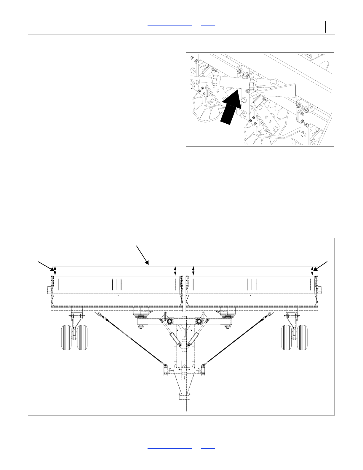
2N-2410 & 2N-3010 Table of Contents Index Drill Preparation and Setup 21
12778
Figure 7
Box Alignment Adjustment
String Line
16306
Measurement A
Measurement A
Measurement B
Measurement B
Figure 8
Box Alignment Measurements
Aligning Boxes
Refer to Figures 7 and 8
For proper alignment, the outside ends of the drill boxes
must be 1 to 1- 1/2 inches ahead of the inside ends.
Follow these steps to check box alignment and adjust
as necessary.
1. With the drill unfolded and lowered, pull forward a
few feet with the openers in the ground.
2. Extend a string line to the outer ends of the wing
boxes as shown in Figure 8. Measure from the
string line to each box as shown. For each box,
measurement A should be 1 to 1-1/2 inches greater
than measurement B.
3. If adjustment is needed, write down how many
inches the box should be moved to be within the 1to 1 1/2-inch tolerance mentioned above. Also note
the direction you need to move the outside end of
the box–forward or back.
4. Make adjustments at the box end of each pull cable
as shown in Figure 8. Loosen the jam nuts on the
adjustment trunnion screw. Turn the screw in or out
to move the box end forward or backward as
required. Tighten the jam nuts.
5. Pull ahead slightly and check the box alignment.
Re-adjust the pull cables if necessary.
8/2/18 Table of Contents Index 196-126M
Page 25

2N-2410 & 2N-3010 Table of Contents Index 22
Operating Instructions
This section will help you prepare the tractor and drill for
use. It will also give you general operating procedures.
Experience, machine familiarity and the following
information will lead to efficient operation and good
working habits. Always operate farm machinery with
safety in mind.
Pre-start Checklist
1. Carefully read “Important Safety Information,”
page 1.
2. Lubricate the drill as indicated under Lubrication,
page 47.
3. Check all tires for proper inflation as indicated on
Tire Inflation Chart, page 57.
4. Check all bolts, pins and fasteners. Torque as
specified on Torque Values Chart, page 57.
5. Check the drill for worn or damaged parts. Repair or
replace them before going to the field.
6. Check hydraulic hoses, fittings and cylinders for
leaks. Repair or replace them before going to the
field.
7. Check disk scrapers for proper adjustment. Refer to
Disk Scraper Adjustment, page 39.
8. Check that the drive-clutch linkage is operating
properly. The clutch jaws should be fully engaged with
the drill in seeding position. When the drill is fully
raised the clutch jaws should be completely
separated.
9. Rotate both gauge wheels to see that seed cups and
drive are working and free from foreign material.
Tractor Requirements
Recommended Minimum Tractor Size
24-foot drill - 200 to 250 horsepower
30-foot drill - 250 to 300 horsepower
NOTE: When determining tractor size, soil type,
terrain and tillage practices must be considered.
Towing the drill at high speeds or with a vehicle that is not
heavy enough can lead to loss of vehicle control. Loss of
vehicle control can lead to serious road accidents, injury and
death. The reduce the hazard:
• Do not exceed 20 mph.
• Use a towing vehicle heavy enough to control the
drill.
Minimum Towing Vehicle Weight
16,000 pounds
8/2/18 Table of Contents Index 196-126M
Page 26
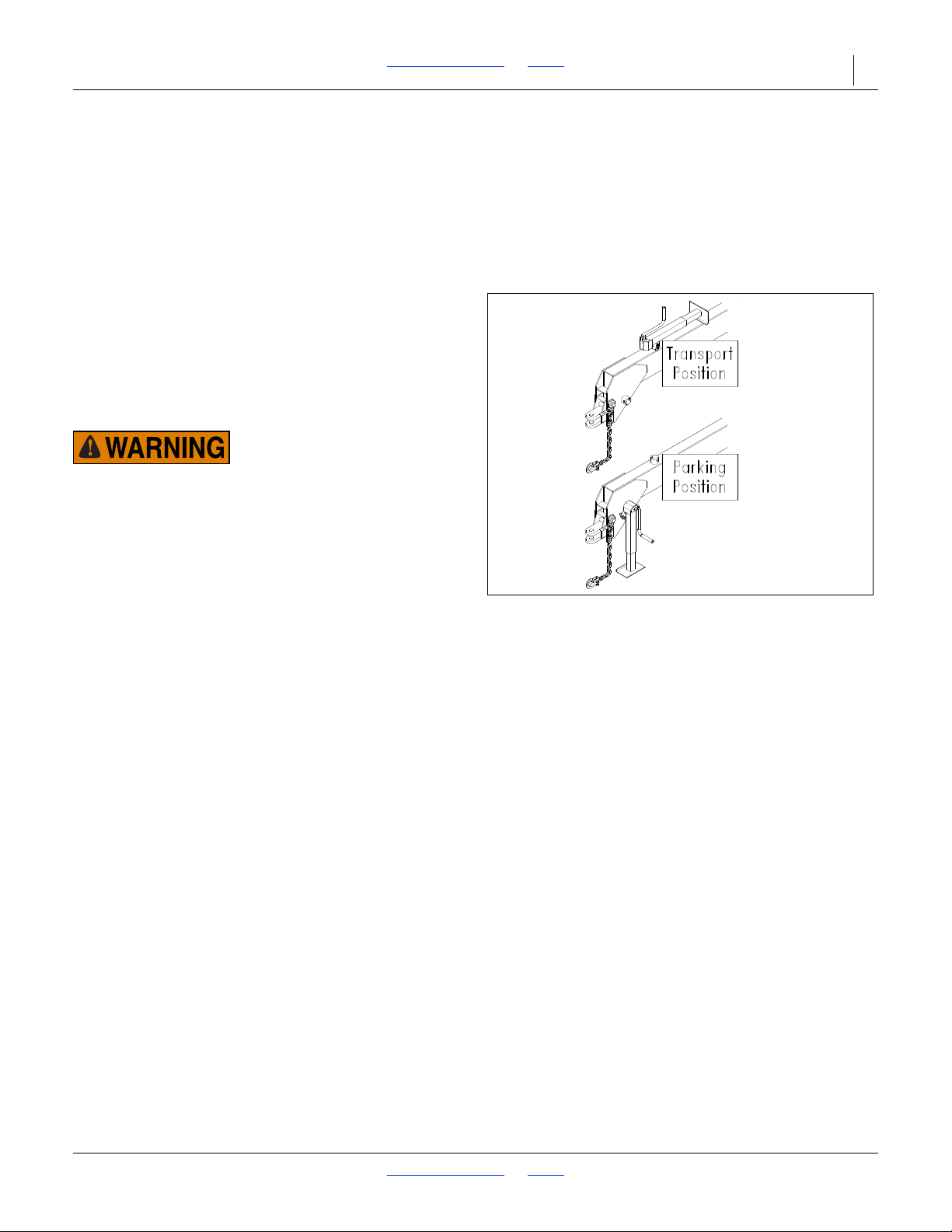
2N-2410 & 2N-3010 Table of Contents Index Operating Instructions 23
12782
Figure 9
Jack Positions
Hydraulics
Your tractor must have two remote outlets.
Safety Lights
Your tractor must be wired for the standard 7-pin
electrical connector. If your tractor is not equipped with
this connector, consult your dealer for installation.
Hitching Tractor to Drill
Refer to Figure 9
1. Use the drill jack to raise or lower the tongue as
needed. Hitch the drill to the tractor using a hitch pin
of adequate strength (at least one inch in diameter).
2. Install a retaining clip on the hitch pin to prevent it
from working up. Securely attach drill safety chain to
tractor drawbar.
Escaping fluid under pressure can have sufficient pressure to
penetrate the skin causing serious injury. Avoid the hazard by
relieving pressure before disconnecting hydraulic lines. Use a
piece of paper or cardboard, NOT BODY PARTS, to check for
leaks. Wear protective gloves and safety glasses or goggles
when working with hydraulic systems. If an accident occurs,
see a doctor immediately.
3. Connect hydraulic hoses to tractor remotes. One pair
of hoses is for the field-lift cylinders. The other pair is
for raise-to-fold, transport-lock, fold and marker
cylinders.
4. Plug the control-console cable to the drill harness.
Plug the drill light cable to the tractor.
5. Crank the jack until tongue weight is resting on the
tractor drawbar. Unpin the tongue jack from the
hitching stub. Pin the jack to the stub on top of the
tongue as shown in Figure 9.
Operating Control Console
Your drill is equipped with a control console that is
mounted in the tractor cab. Refer to Installing Drill
Control Consoles, page 16. The console is designed to
control drill folding and optional markers, electric
clutches and shaft monitors. The console has a master
switch that must be on when operating any of these
systems.
The raise-to-fold, transport locks and fold switches are
operated independently. Turn only one of these switches
on at one time. During field operations, turn all three
switches off.
To operate markers, turn the marker switch to the left
position during field operation. Turn this switch to the
center position (off) when folding or in transport.
8/2/18 Table of Contents Index 196-126M
Page 27

2N-2410 & 2N-3010 Table of Contents Index Operating Instructions 24
Operating Electric Clutch Consoles
To operate electric clutches, turn either the left or right
clutch switch to the off position to shut down the seeding
from the corresponding box. Turn the electric clutch
switches off when folding or in transport.
To operate shaft monitors, turn the shaft monitor switch
on during field operation and off when folding or
transporting.
Folding the Drill
To prevent serious injury or death:
Always use transport locks when drill is folded.
•
Fold only if hydraulics are bled free of air and fully charged with
•
hydraulic oil.
Stay away from frame sections when they are being raised or low-
•
ered.
Keep away and keep others away when folding or unfolding the
•
drill.
Fold the drill on level ground with the tractor in neutral. If
your drill has markers, be certain they are folded and
their control switches are off before folding. If your drill
has a harrow attachment, fold the attachment before
folding the drill. Refer to Folding Harrow Attachment,
page 25.
1. Raise drill with field-lift cylinders until cylinders are
fully extended.
2. Turn on master power switch on control console.
Turn on raise-to-fold switch.
3. Work tractor hydraulic lever to raise drill into fold
position.
4. Turn off raise-to-fold switch. Turn on transport-locks
switch.
5. Work tractor hydraulic lever to extend lock cylinders.
If lock cylinders will not extend, drill is not fully raised;
repeat steps 1 through 3.
If your tractor is equipped with hydraulic flow
controls, adjust flow-control valve for this circuit to
the slowest position.
6. Turn off transport-locks switch. Turn on fold switch.
7. Work tractor hydraulic lever to slowly retract fold
cylinders.
Never attempt to fold without first operating the raise-to-fold
and transport-lock systems. Otherwise, serious equipment
damage will occur.
8/2/18 Table of Contents Index 196-126M
Page 28

2N-2410 & 2N-3010 Table of Contents Index Operating Instructions 25
Once drill is folded over transport carriers, turn off fold
switch. Turn on raise-to-fold switch.
Work tractor hydraulic lever to lower boxes onto carriers.
Turn off raise-to-fold switch.
Folding Harrow Attachment
Before hydraulically folding drill, fold optional coil-tine
harrow as explained below.
Fold right-hand harrow assembly up until locking pin
engages into the first slot on harrow bracket.
Fold left-hand harrow assembly up until locking pin
engages into the second slot on harrow bracket.
Unfolding the Drill
This drill has negative tongue weight when unfolded and
raised. Be certain the drill is hitched securely to your
tractor drawbar and the hitch safety chain is securely
attached to the tractor before raising or unfolding the drill.
To prevent serious injury or death:
Always use transport locks when drill is folded.
Fold only if hydraulics are bled free of air and fully
charged with hydraulic oil.
Stay away from frame sections when they are being
raised or lowered.
Keep away and keep others away when folding or
unfolding drill.
Unfold the drill on level ground with the tractor
transmission in neutral.
1. On control console, turn on raise-to-fold switch.
2. Work tractor hydraulic lever to raise boxes off
transport carriers.
3. Turn off raise-to-fold switch. Turn on fold switch.
4. Work tractor hydraulic lever to slowly unfold drill
boxes.
5. When drill is unfolded completely, turn off fold switch.
Turn on transport-lock switch.
6. Work tractor hydraulic lever to retract transport-lock
cylinders.
If transport-lock cylinders will not retract, drill is not
raised fully. Make sure field-lift cylinders and
transport-lift cylinders are extended fully.
7. When transport-lock cylinders are retracted, turn off
transport-lock switch. Turn on raise-to-fold switch.
8. Work tractor hydraulic lever to lower drill.
9. Turn off raise-to-fold switch.
8/2/18 Table of Contents Index 196-126M
Page 29

2N-2410 & 2N-3010 Table of Contents Index Operating Instructions 26
Lifting the Drill in the Field
Your drill is raised for field operations with hydraulic
cylinders in a master-slave configuration. Over a period
of normal use the cylinders may get out of phase. This
will cause one side of the drill to run higher. To rephase
the cylinders:
1. Raise the drill completely with the field-lift cylinders.
Hold the hydraulic lever on for several seconds until
all cylinders are fully extended. This should be done
every time the implement is raised out of the ground.
2. When all field-lift cylinders are fully extended,
momentarily reverse the hydraulic lever to retract the
system 1/2 inch. This will help maintain levelness.
Air in the field-lift system will cause jerky and uneven
cylinder movement. Follow procedures under
Bleeding Hydraulic Systems, page 17, to properly
bled air from the system.
Field Operations
For normal seeding operations:
1. Hitch drill to a tractor with sufficient weight and
horsepower. Refer to Tractor Requirements, page
22, and Hitching Tractor to Drill, page 23.
2. Perform all checks listed on Pre-start Checklist, page
22.
3. Lower the drill into seeding position.
4. Observe the drill from the side. Check that the
tongue is running level with the ground. If not, refer to
Hitch Height Adjustment, page 15.
5. Set the seeding rate for both boxes. Refer to Setting
the Seeding Rate, page 37. Make sure the seeding
rate is the same across the drill.
6. Load boxes with clean seed.
7. Record the acremeter readout. The acremeter is
mounted on the outside end of the left gauge-wheel
shaft. Subtract this initial readout from later readings
to calculate area drilled.
8. Pull forward, lower drill, and begin seeding.
9. Always lift the drill out of the ground when turning at
row ends and for other short turns. Seeding will stop
automatically as the drill is raised in the field.
This drill is offered in three different row spacings.
Some of the drill boxes do not have the same
number of seed cups between each internal box
divider. The section with the largest number of cups
will empty sooner.
8/2/18 Table of Contents Index 196-126M
Page 30

2N-2410 & 2N-3010 Table of Contents Index Operating Instructions 27
Opener Operation
Never back up with openers in ground. If you do, check
all openers to be sure none are clogged or damaged.
For information on setting seed depth and opener
adjustments, see No-Till Seeding, page 30, and Leveling
Adjustments, page 39. For more information on
troubleshooting opener problems, see
“Troubleshooting,” page 43.
Marker Operation
Optional marker attachments are sold as single (lefthand) or dual units. The markers are operated on the
same electro-hydraulic circuit as the raise-to-fold,
transport-lock and folding functions.
Before operating the markers, make sure they are
properly bled as described under Marker Hydraulics,
page 19.
To operate the markers, turn the control-console switch
to the left marker position after the drill is unfolded.
Activate the hydraulic lever to fold or unfold the marker.
The dual markers are equipped with a sequencing valve
to ease marker operation. Starting with both markers
folded, the sequence is:
1. Activate lever. Right unfolds; left marker stays
folded.
2. Reverse lever. Right folds up; left stays folded.
3. Activate lever. Left unfolds; right stays folded.
4. Reverse lever. Left folds up; right stays folded.
5. Sequence repeats.
Because of the sequencing valve, do not turn marker
switch between the left and right positions on the
control console. The left-marker position controls
both markers. If you wish to operate the markers
independently, contact your Great Plains dealer for
additional parts to modify the marker hydraulics.
Markers are equipped with needle valves to set folding
speed. Refer to Folding Speed, page 41, and adjust
folding speed to a safe rate. Folding or unfolding markers
at high speed can damage markers.
When marker operation is complete, return markers to
the folded position and turn the marker switch to the
center (off) position.
8/2/18 Table of Contents Index 196-126M
Page 31
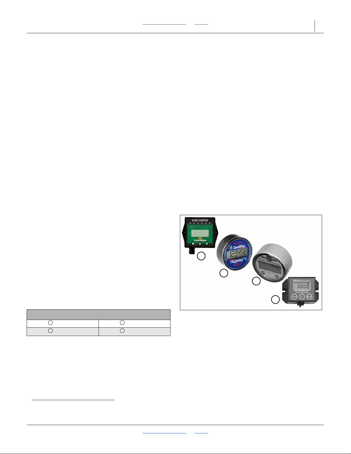
2N-2410 & 2N-3010 Table of Contents Index Operating Instructions 28
1
2
3
4
38110
Figure 10
Acremeter Variations
1
3
2
4
Shaft Monitor Operation
To operate the optional shaft monitors, turn the shaftmonitor switch on the control console to the on position.
If either seed-cup shaft stops for 20 seconds, an alarm
will sound. A light on the control console will designate
the failed shaft.
The 20-second delay is to prevent nuisance alarms when
turning at the end of the field. If the alarm sounds,
remember you have traveled for 20 seconds without
seeding.
Electric Clutch Operation
Electrical clutches on the upper jack shaft turn seeding
off and on as the drill is raised and lowered in the field.
The electric clutches allow you to turn seeding off while
the drill is lowered. A clutch for each drive shaft allows
you to control each drill box independently. The clutches
are controlled through the in-cab control console.
For regular field operation, turn the electric-clutch
switches on the control console to the on position. This
will activate the magnet on each clutch and allow the
clutch shafts to rotate.
To shut off seeding in one or both boxes while the drill is
lowered, turn one or both switches to the off position.
Acremeter Operation
The acremeter1 counts shaft rotations whenever the
shaft is rotating - normally this is only with the drill
lowered and in motion. The meter is programmed to
display rotations as acres or hectares, when using all
rows, factory-specified tires and tire inflations.
Unusual conditions and/or non-standard row
spacings can cause the acremeter tally to vary
somewhat from actual acres planted.
Refer to Figure 10
Acremeters supplied with drills have varied over time. For
operational details (modes, resets, calibration), see the
manual supplied with the acremeter:
Meter Style and Manual
194-074M 152-314M
152-325M 194-209M
1. An electronic acremeter is available as an upgrade for older drills having a mechanical acremeter.
8/2/18 Table of Contents Index 196-126M
Page 32

2N-2410 & 2N-3010 Table of Contents Index Operating Instructions 29
Transporting
This implement should never be towed faster than 20 mph.
Before transporting, check and practice the following
items.
Fold Drill. Transport the drill in folded position with
transport-lock cylinders extended. Refer to Folding the
Drill, page 24.
Loaded Boxes. This drill can be transported with boxes
loaded with grain, but only with extreme caution. The
additional weight reduces maneuverability and increases
stopping distance.
Stopping Distance. Keep the weight of this drill in mind.
Allow sufficient stopping distance at all times. Reduce
speed prior to making any turns or other maneuvers.
Increase stopping distance if transporting with loaded
boxes.
Bystanders. Check that no one is in the way before
moving. Do not allow anyone to ride on the drill.
Tractor Requirements. Check that the towing vehicle is
large enough to control the drill on the road. Refer to
Tractor Requirements, page 22.
Clearance. Know drill dimensions in transport position
and follow a route that provides adequate clearance from
all obstructions. Refer to Specifications and Capacities,
page 55.
Tires. Check that all tires are properly inflated as listed
on Tire Inflation Chart, page 57.
Road Rules. Comply with all federal, state and local
laws when transporting on public roads.
Warning Lights. Always use warning lights when
transporting the drill.
Watch Traffic. Be prepared for sudden maneuvers from
following vehicles.
Markers. Always transport optional markers folded flat.
Make sure the second marker section rests securely on
the transport carrier.
Harrow Attachment. Fold the optional harrow
attachment before hydraulically folding drill for transport.
Refer to Folding Harrow Attachment, page 25.
Parking
Perform the following steps when parking the drill. Refer
to Storage, page 45, for information on long-term storage
preparation.
1. Raise, lock and fold the drill in the transport position.
Refer to Folding the Drill, page 24.
2. Park the drill on a level, solid area.
3. Securely block the tires to prevent rolling.
4. Remove the jack from its storage stub. Pin the jack in
parking position. See Figure 9, page 23. If the
ground is soft, place a board or plate under the jack.
5. Extend the jack until tongue weight is off the
drawbar.
6. Unplug the hydraulic lines from the tractor. Do not
allow hose ends to rest on the ground.
7. Unplug the control-console cable from the tractor.
Unplug the drill light cable from the tractor.
8. Remove hitch pin and safety chain from tractor
drawbar.
8/2/18 Table of Contents Index 196-126M
Page 33

2N-2410 & 2N-3010 Table of Contents Index 30
Adjustments
No-Till Seeding
To get full performance from your no-till drill, you need a
good understanding of coulter, opener and press wheel
operation.
Coulters. A no-till coulter is mounted independently and
directly ahead of each opener. The coulters cut through
heavy trash and make a groove in the soil. The coulters
are mounted directly on the box frame. Consequently,
the cutting depth of all coulters changes as the drill is
raised and lowered. The cutting depth of the coulters is
controlled by an adjustable hydraulic depth stop.
Coulters that run directly in tire tracks can be lowered
individually. Refer to Coulter Adjustments, this page, for
information on how to make these adjustments.
Openers. Each opener is mounted on the drill with
parallel arms. This parallel-action mounting allows the
opener to move up and down while staying in-line with a
coulter. Opener double disks widen the coulter groove,
making a seed bed. A seed tube mounted between the
disks delivers seed to the trench.The down force needed
to cut and widen the coulter groove is supplied by two
springs nested in the parallel linkage. Adjusting these
springs changes opener down-force. Refer to Opener
Down-Pressure Adjustment, page 36, for information on
how to make this adjustment.
Press Wheels. Attached to the rear of each opener is
one of several press-wheel options. The press wheels
provide two important functions.
First, the press wheels close the furrow, gently pressing
the soil over the seed. To provide consistent seed
firming, the press wheels are free to move downward
from their normal operating position. This system
maintains pressing action even if the opener arm is lifted
when the disks encounter obstructions.
Second, the press wheels provide opener depth control.
The higher the press wheels run relative to the double
disks, the deeper seed will be placed. To maintain a
consistent depth, upward press-wheel movement is
restricted by an independently adjustable stop on each
opener. Refer to Press Wheel Adjustment, page 36, for
information on how to make this adjustment.
Coulter Adjustments
The drill is assembled so that when the coulters are at
two inches deep, the seeding depth is about one inch.
This is a good baseline setting for most seeding
operations. As field conditions warrant, you can change
settings on the entire drill or individual coulters.
8/2/18 Table of Contents Index 196-126M
Page 34
2N-2410 & 2N-3010 Table of Contents Index Adjustments 31
Raise Coulters
16271
4
2
Lower Coulters
1
3
Raise Coulters
16271
4
2
Lower Coulters
1
3
16271
4
2
1
3
A
B
Figure 11
Left Transport-Wheel Cylinder with Depth-Control Stop
AB123
4
Hydraulic Depth Control
Refer to Figure 11
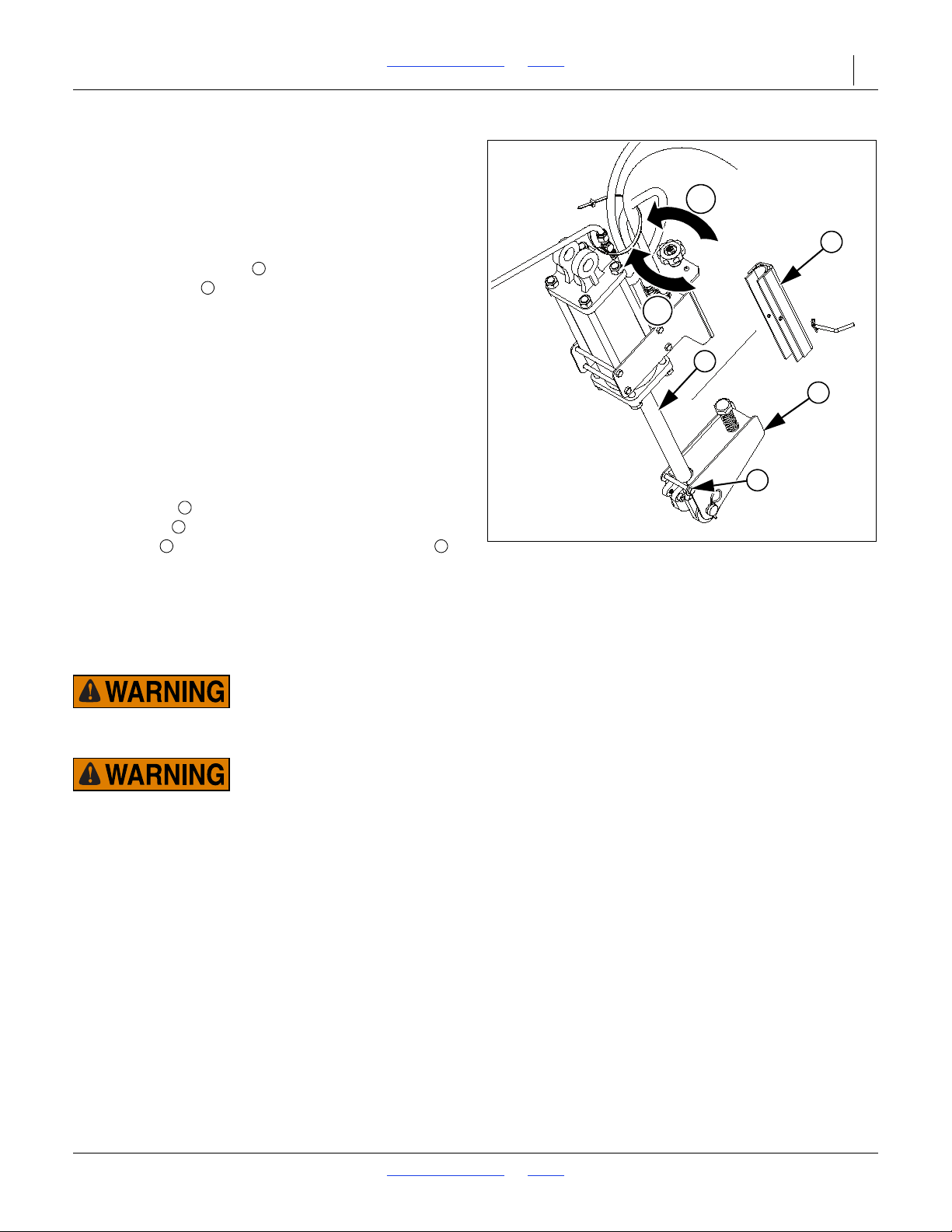
The master field-lift cylinder on the left-hand transport
wheel is equipped with a hydraulic valve that regulates
coulter depth. Figure 11 shows the valve and knob
used to adjust coulter depth.
Turn the knob clockwise to lower the coulters and
counter-clockwise to raise the coulters. Each rotation
will move the coulters approximately 3/32 inches. Make
depth adjustments with the implement slightly raised.
After adjusting the valve, raise and lower the implement
several times and recheck coulter depth.
The depth stop regulates depth on all coulters. If the
ends of either box run higher or lower than the center,
the field-lift system may be out of phase or have air in it,
or the frame sections may not be level. Refer to Lifting
the Drill in the Field, page 26, Bleed Field-Lift
Hydraulics, page 17, or Leveling Adjustment, page 39.
When performing maintenance operations, the cylinder
lock channels must be installed on the field-lift
cylinder rods . On the left-hand field-lift cylinder,
remove bolt from the lower depth stop assembly .
Rotate the lower depth stop assembly out of the way to
prevent damage both the lower depth stop assembly
and the lock channel. Refer to Cylinder Lock Channels,
page 46.
The cylinder lock channels must be installed in the
storage location on the mainframe during transport.
The cylinder lock channel must not contact the lower depth
stop assembly or damage will occur.
The cylinder lock channels must not be installed on the
field-lift cylinder rods during transport or damage can occur.
8/2/18 Table of Contents Index 196-126M
Page 35
2N-2410 & 2N-3010 Table of Contents Index Adjustments 32
19711
Figure 12
Electric Clutch Switch
15160
Figure 13
14550
Figure 14
Electric Clutch Switch Adjustment
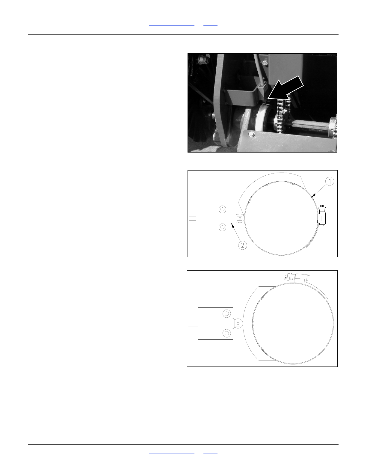
To adjust the height at which seed metering is turned
off, follow these steps.
Refer to Figure 12
1. Locate the height switch at left-hand gauge wheel.
2. Lower the implement until it is at a height where
seeding should start (usually just above the
ground). Securely support frame at this height with
jack stands or blocks.
3. Turn off the tractor and remove the key.
Refer to Figure 13
4. Loosen the cam clamp (1) on the gauge wheel
rockshaft and turn until the switch roller (2) is just
starting to make contact with the ramp surface.
Refer to Figure 14
5. Raise the implement fully and check that the switch
is compressed as shown.
8/2/18 Table of Contents Index 196-126M
Page 36
2N-2410 & 2N-3010 Table of Contents Index Adjustments 33
38169
Figure 15
Pull Cable
38170
Figure 16
Twist Direction
Pull Cable Adjustments
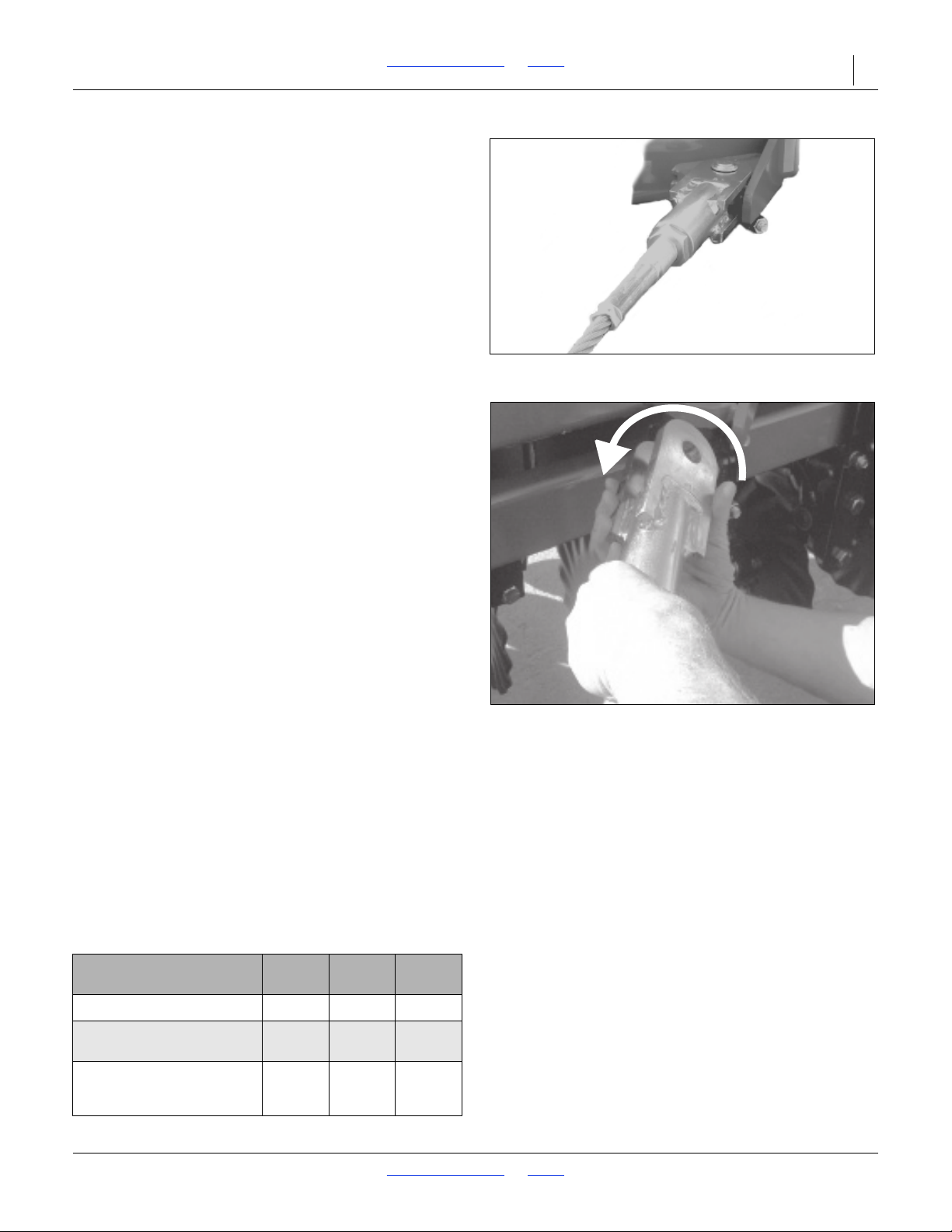
Refer to Figure 15
1. To adjust the pull cables, loosen the jam nut on the
adjustment trunnion screw, and adjust the screw
either in or out to move the box end forward or
backwards as required. Once adjusted, re-tighten
the jam nut.
2. Pull ahead slightly and re-check the box alignment.
Readjust the pull cables if necessary.
Refer to Figure 16
3. The pull cables need to be twisted to allow for proper
movement during folding and unfolding operations.
To do this, face towards the left hand box frame and
remove the pin from the adjustable clevis on the pull
cable. Taking the adjustable clevis and pull cable as
one, turn or twist this end of the cable one complete
turn towards the center of the machine and re-pin the
clevis.
4. Face towards the right hand box frame and remove
the pin from the adjustable clevis on the pull cable.
Take the adjustable clevis and pull cable as one, then
turn or twist this end of the cable one complete turn
towards the center of the machine and re-pin the
clevis.
5. Once both pull cables have been properly twisted,
carefully fold and unfold the drill.
6. Tighten all bolts as specified on the ‘Torque Values
Chart’ on page 57.
Weights
If more weight is required for coulters to penetrate the
soil, weight bracket kits are available from your Great
Plains dealer. Refer to Weight Brackets, page 51 for part
numbers and ordering information.
Refer to the charts below for the results of adding
weights to your drill. Always add an equal amount of
weight to each box frame. Never add more than 500
pounds to each box frame.
Weight Chart, 24-Foot Drill
7 1/2-in.
Rows
Empty Drill, Pounds 17,400 17,100 16,000
Pounds Per Coulter, No
Weights
Pounds Per Coulter,
Brackets and 1000 Pounds
Added
8/2/18 Table of Contents Index 196-126M
305 320 390
330 340 420
8-in.
Rows
10-in.
Rows
Page 37
2N-2410 & 2N-3010 Table of Contents Index Adjustments 34
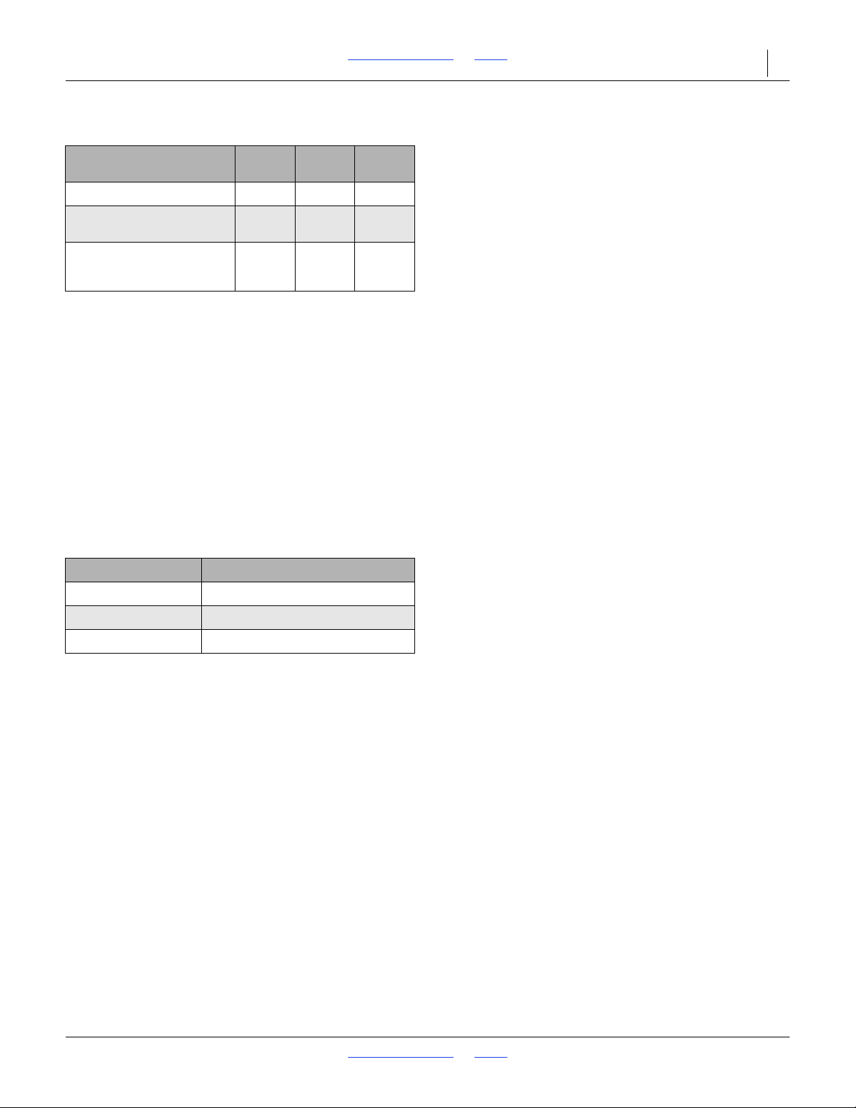
Weight Chart, 30-Foot Drill
7 1/2-in.
Rows
Empty Drill, Pounds 20,100 19,600 18,400
Pounds Per Coulter, No
Weights
Pounds Per Coulter,
Brackets and 1000 Pounds
Added
285 300 335
305 325 385
8-in.
Rows
10-in.
Rows
Optional markers, harrows and small-seed
attachments add about 25 pounds per coulter.
Completely loading the grain or small-seed boxes
adds about 100 pounds per coulter.
Coulter Springs
The coulter spring length is preset at 10 inches, giving
the coulter an initial operating force of 400 pounds. This
setting is adequate for many difficult no-till conditions.
For lighter no-till conditions where rocks or other
obstructions are a problem, you can lengthen the
springs to protect the coulters from impact. In heavier
conditions, shortening the spring will increase coulter
force. Refer to the chart below for adjusting the coulter
springs.
Coulter Down-Pressure Chart
Spring Length Coulter Force
10-1/4 in. 300 lb.
10 in. 400 lb.
9-3/4 in. 525 lb.
Any attempt to reset the coulter spring length shorter
than 9 3/4 inches may contribute to premature failure
of parts and warranty will be voided. If additional
force is necessary, add weights to the implement.
8/2/18 Table of Contents Index 196-126M
Page 38
2N-2410 & 2N-3010 Table of Contents Index Adjustments 35
10300
Figure 17
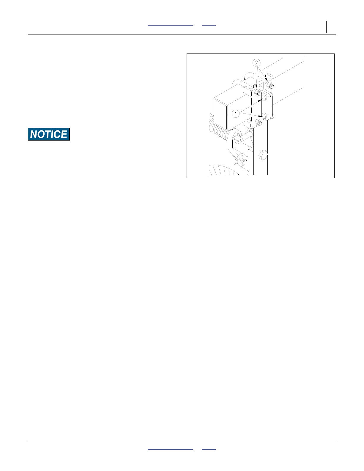
Individual Coulter Height Adjustment
Individual Coulters
Refer to Figure 17
When coulters follow in tire tracks and do not give
satisfactory depth, individual coulters can be lowered
by loosening the mounting clamps and adjusting the
coulter to the desired setting.
To tighten clamps, snug the hex-head clamp bolts (1)
just until the U-bolts are tight on each side of the spring
bar. Tighten nuts on U-bolts (2), then finish tightening
the hex-head clamp bolts.
Never lower any coulter more than 1 1/2 inches. Tire damage
could result as the drill is folded. Also note that when the drill
is in the raised position, ground clearance on lowered coulters
is reduced.
There may be as much as a 1/8-inch gap between
the clamp plates even when the coulter is mounted
securely.
8/2/18 Table of Contents Index 196-126M
Page 39
2N-2410 & 2N-3010 Table of Contents Index Adjustments 36
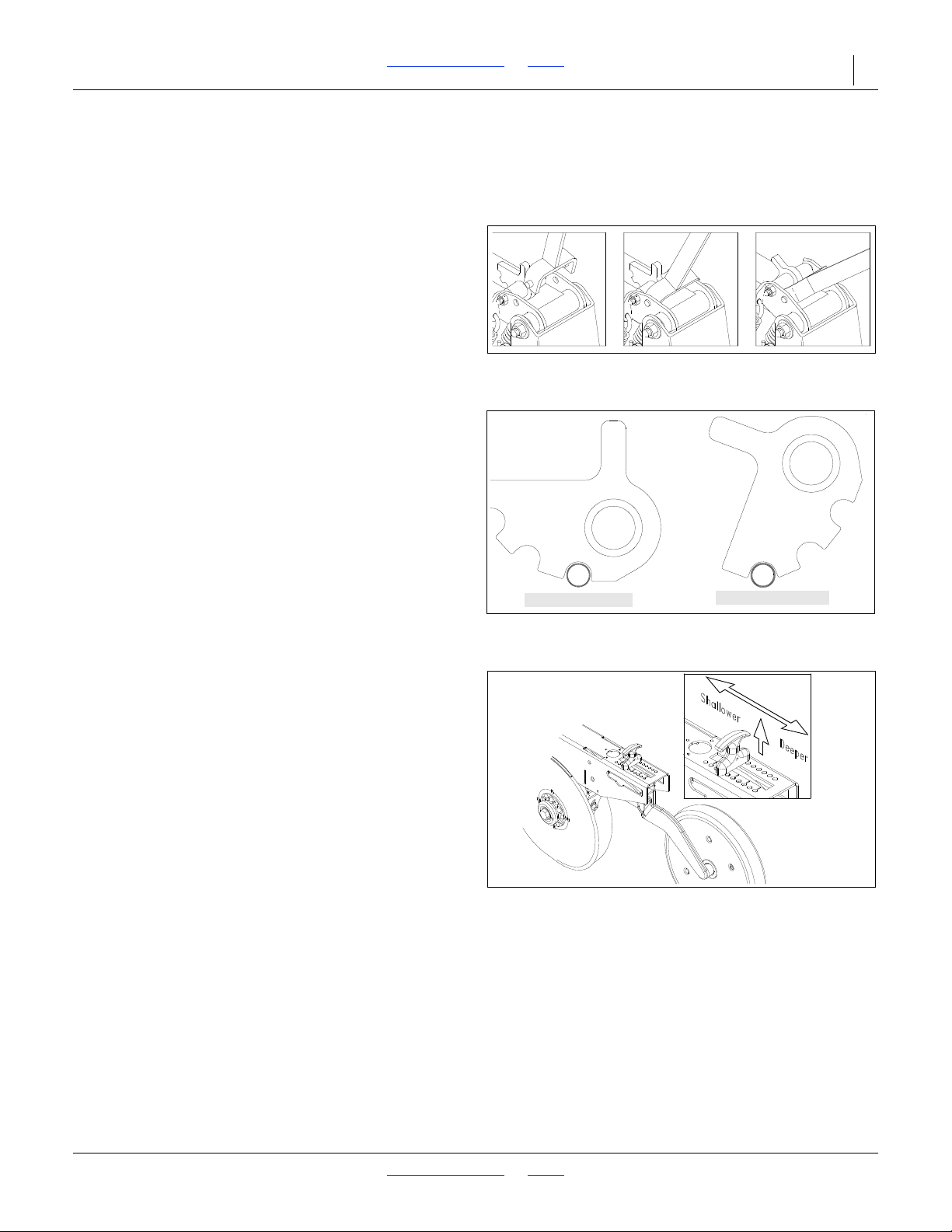
12105
Figure 18
Opener-Spring Adjustment
Minimum Force
Maximum Force
12104
Figure 19
Spring Settings
12100
Figure 20
Press Wheel Adjustment
Opener Down-Pressure Adjustment
You can adjust spring down pressure individually for
each opener. This is useful for penetrating hard soil and
planting in tire tracks.
Refer to Figure 18
To adjust down pressure, use the adjustment tool
stored under the walkboard. Position the tool in the
holes on the spring mounting plates and pull down on
the adjuster as shown.
Refer to Figure 19
Minimum and maximum settings are indicated by the
position of spring adjuster.
Press Wheel Adjustment
Refer to Figure 20
Changing the height of the press wheel automatically
changes seeding depth. To adjust, lift up on the Thandle and slide it forward or back.
• For shallower seeding, slide the handle toward the
implement.
• For deeper seeding, slide the handle away from the
implement.
8/2/18 Table of Contents Index 196-126M
Page 40
2N-2410 & 2N-3010 Table of Contents Index Adjustments 37
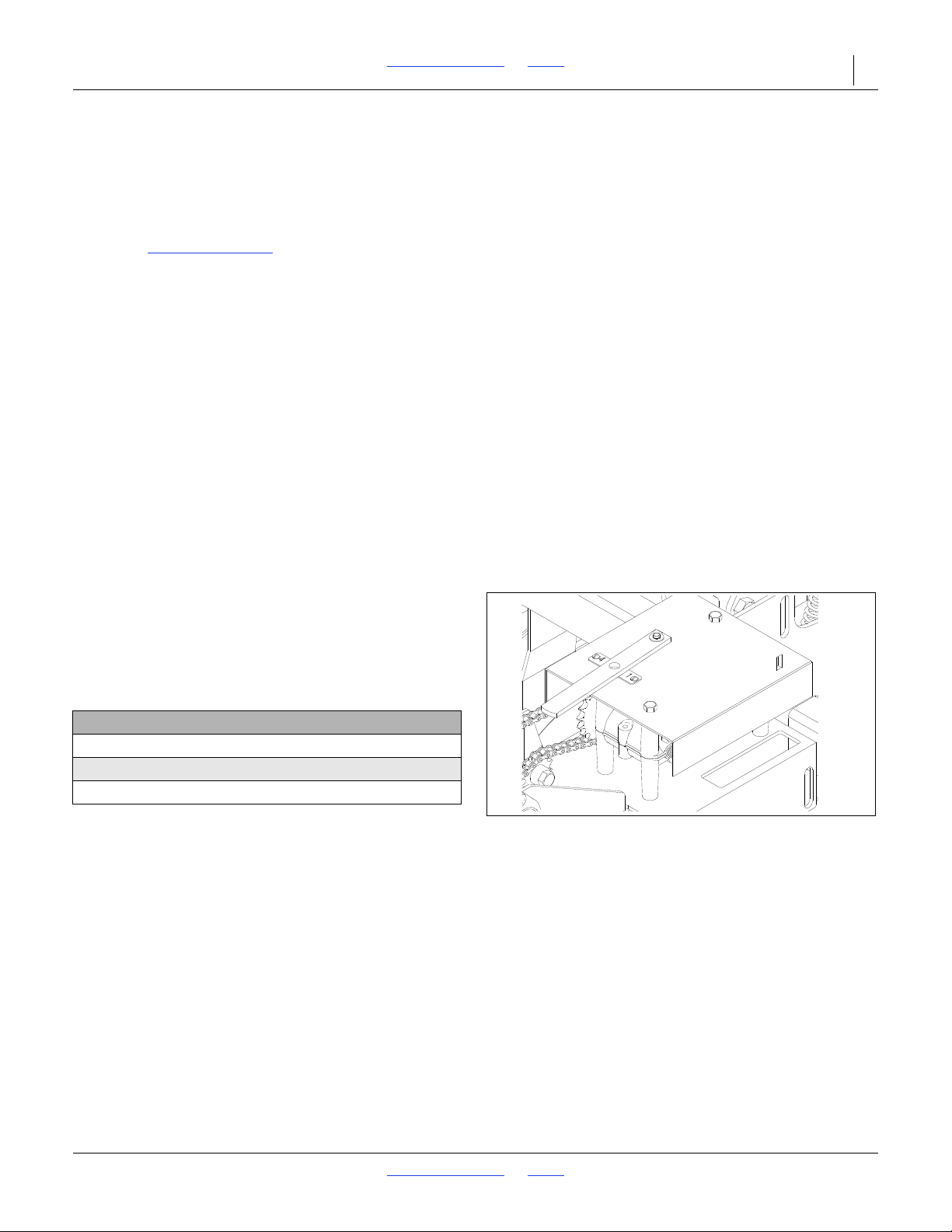
12916
Figure 21
Speed-Change Gearbox
Setting the Seeding Rate
Calibrating the seeding rate requires four steps: shifting
the speed-change gearbox, adjusting the seed-rate
handle, setting the seed-cup doors, and checking the
seeding rate.
Check the Seed-Rate Charts
charts list the proper settings for the speed-change
gearbox and seed-rate handle for various seeds and
seeding rates.
The seed-rate charts are based on cleaned, untreated
seed of average size and test weight. The rates are
based on 11L x 15 8-ply rib implement tires and
265/70B16 skid steer tires. Many factors will affect
seeding rates including foreign material, seed treatment,
seed size, field conditions, tire pressure and test weight.
Minor adjustments likely will be needed. Set and check
the seeding rate using the procedures below, then readjust the rate as necessary.
Before setting the seeding rate, rotate both gauge
wheels to see that the seed cups and drive are working
properly and free from foreign material.
Each drill box has its own metering mechanism.
After adjusting and checking the rate on one box, set
the same rate on the other box.
1. Shift Speed-Change Gearbox
Refer to Figure 21
The speed-change gearbox is designed to give you
a variety of speeds for different seeds and seeding
rates. You can shift between four different drive
types.
Gearbox Ratios:
Drive Type 2 is 2.06 Times Faster Than 1
Drive Type 3 is 3.08 Times Faster Than 1
Drive Type 4 is 5.03 Times Faster Than 1
or in the drill boxes. These
Refer to the seed-rate charts for the correct drive
type–1, 2, 3 or 4. Move the selector handle on the
gearbox until the correct number appears in the
handle window as shown in Figure 21. Rotate the
tires a few turns to confirm the gearbox has
engaged.
8/2/18 Table of Contents Index 196-126M
Page 41
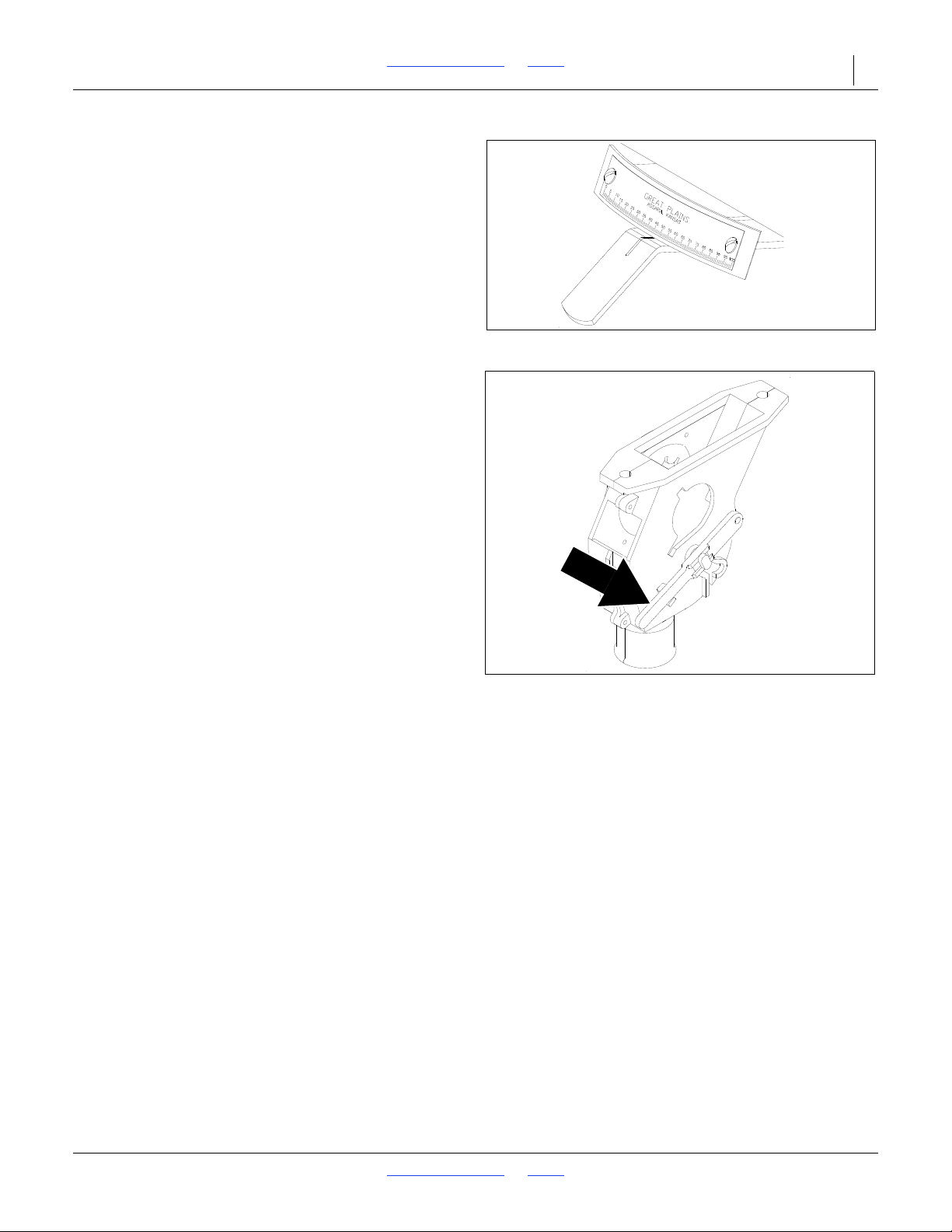
2N-2410 & 2N-3010 Table of Contents Index Adjustments 38
12927
Figure 22
Seed-Rate Handle
13867
Figure 23
Seed-Cup Door Handle
2. Adjust Seed-Rate Handle
Refer to Figure 22
Position the handle to the setting indicated on the seedrate chart. To adjust, loosen the wing nut under the
handle and slide until indicator lines up with desired
setting. Tighten nut.
3. Set Seed-Cup Doors
Refer to Figure 23
For wheat and other small seeds, move the seedcup-door handles to the highest position. For
soybeans and other large seeds, lower the handles
to the second position. If excessive seed cracking
occurs, lower the handles to the third position. For
seed-cup clean out, move the handles to the fourth,
wide-open position. Make sure all handles are in
the same position before drilling.
4. Check Seeding Rate
a. Place several pounds of seed over the three
seed cups on the outside end of the drill box.
b. Disconnect the seed tubes from the three
openers fed by the covered cups.
c. Raise the drill off the ground.
d. Record the empty weight of a container large
enough to hold the seed metered for one acre.
e. Turn gauge wheels until seed drops to the
ground from each cup.
f. Place a container under the three seed tubes to
gather the seed as it is metered.
g. Rotate the gauge wheel until one acre has
been tallied on the acremeter. This will be
about 225 rotations on a 24-foot drill and about
181 rotations on a 30-foot drill. Check that the
seed cups have plenty of seed coming into
them.
h. Weigh the metered seed. Subtract the initial
weight of the container. Divide by three.
Multiply by the number of openers on your drill
for the pounds-per-acre seeding rate. If this
figure is different than desired, re-adjust the
seed-rate handle and recheck the rate.
5. When satisfied with the seeding rate, repeat steps 1
through 3 for the other drill box, setting it to the same
rate.
8/2/18 Table of Contents Index 196-126M
Page 42
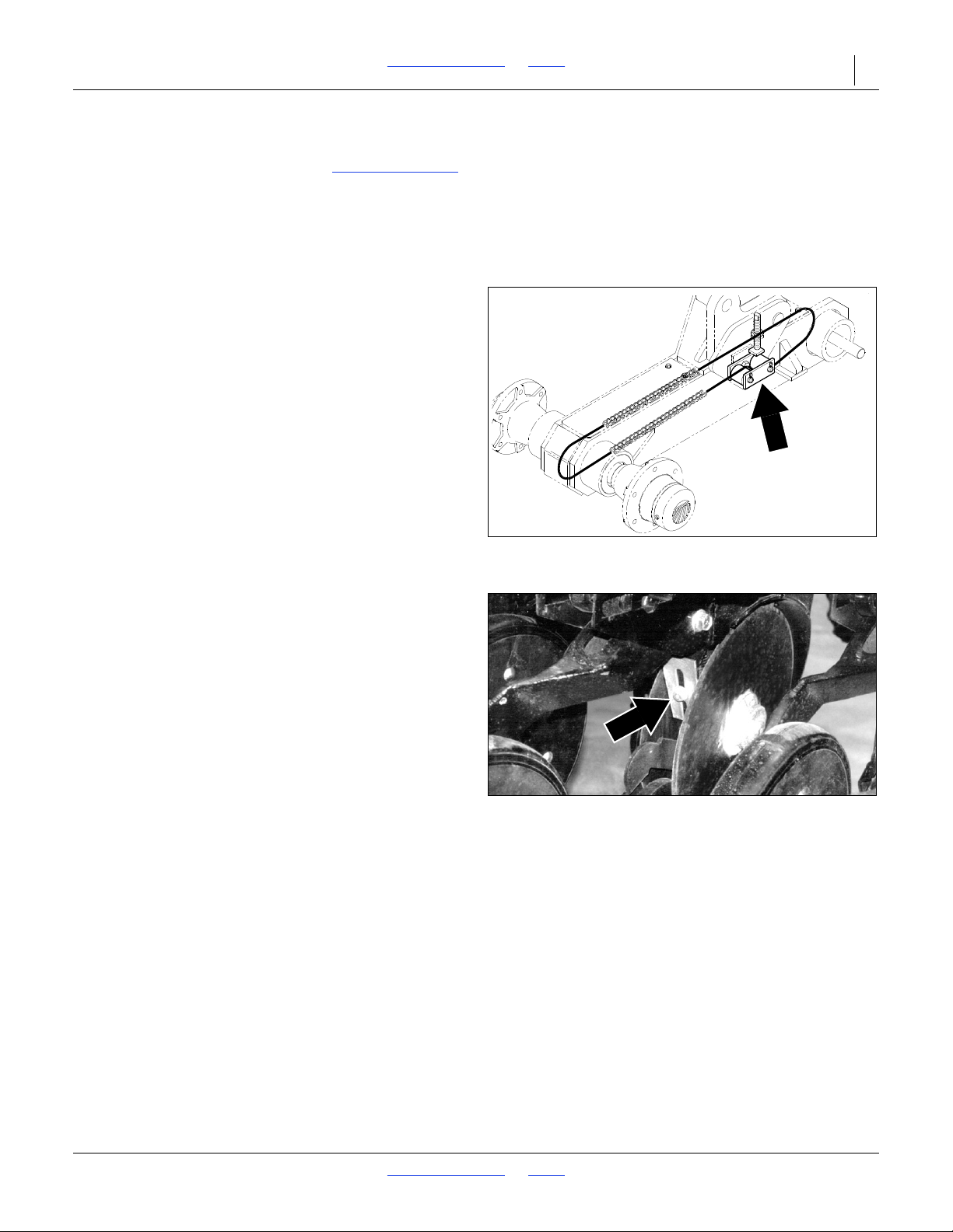
2N-2410 & 2N-3010 Table of Contents Index Adjustments 39
14528
Figure 24
Gauge-Wheel Idler-Sprocket Adjustment
16163
Figure 25
Disc-Scraper Adjustment
Small Seeds Attachment
To set the seeding rate, refer to the Seed-Rate Charts
Move the seed-rate handle on the attachment to the
setting indicated on the chart.
To calibrate the attachment to your material, follow the
steps listed under Check Seeding Rate, page 38.
.
Gauge-Wheel Drive Adjustment
Refer to Figure 24
Inside both gauge-wheel arms are two idler sprockets.
Adjust these sprockets after the first 100 acres of drill
use and at the beginning of each season.
To adjust, move the front idler sprocket on the top of the
chain down by loosening the jam nut and screwing in
the adjustment stud, located on top of the wheel arm.
Do not over tighten chains, causing excessive wear.
Tighten the jam nut to maintain the idler position.
Disk Scraper Adjustment
Refer to Figure 25
To keep the double-disk openers turning freely, dirt
scraper are mounted between the disks to clean as the
disks rotate. As field conditions vary, you may need to
adjust the scrapers. In damp conditions, the scrapers
may need to be lowered. If openers are not turning
freely, the scrapers may need to be raised. To adjust
scrapers, loosen the 3/8-inch bolt and move scraper as
needed.
The optional Air Design disk scrapers are self-
adjusting.
Leveling Adjustment
Equal coulter depth across the implement can only be
maintained if all frame sections are level. Periodic frame
leveling should not be necessary. If your drill appears to
lift or plant unevenly, check the following before releveling the drill.
First, make sure the tongue is level to the ground while
running in the field. Refer to Hitch Height Adjustment,
page 15.
Second, check the field-lift cylinders. Be sure they are
properly bled, operating correctly, and do not have
internal oil leaks.
If leveling is necessary, follow instructions under Frame
Leveling Adjustment, page 20.
8/2/18 Table of Contents Index 196-126M
Page 43
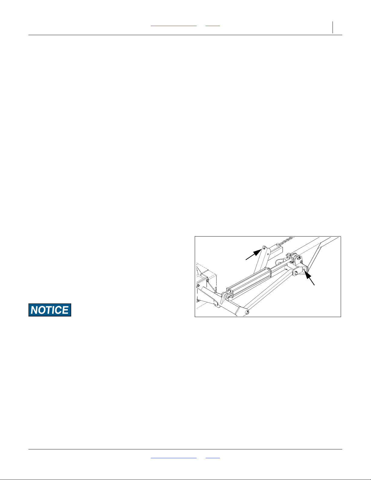
2N-2410 & 2N-3010 Table of Contents Index Adjustments 40
Adjustment Bolt
Shear Bolt
13008
Figure 26
Full-Threaded Adjustment Bolt
Marker Adjustments
Marker Chain
There are two marker chain adjustments–lifting slack and
folding slack. These adjustments should be performed
during initial marker assembly, but additional adjustment
may be needed. The adjustments are interrelated and
should be made in the following order:
Lifting Slack
1. Start with the marker in the unfolded position.
Back the full-threaded adjustment bolt down until
the head extends as little as possible. Slowly fold
the marker, observing the motion of the disk. If
the marker disk slides across the ground more
than about one foot before the chain and linkage
lifts it up, the chain is too slack. Tighten the chain
by moving the clevis one or two links at the
inside end of the chain. Recheck by repeating
this process.
2. If the chain does not have enough slack when
the marker is in the unfolded field position, the
chain will prevent the end of the marker from
dropping into field depressions. Correct this
condition by moving the utility clevis one or two
links, giving the chain more slack.
Folding Slack
Refer to Figure 26
After the adjustments in step one have been
completed, fold the marker. The adjustment bolt is
provided to take the slack out of the chain while the
marker is in the folded position. Extend this bolt until
the slack is out of the chain. Lock the bolt in this
position by tightening the nuts on either side of the
upright channel on the first marker section.
To prevent marker damage, the marker arm is attached to the
marker body with a 7/16-inch, grade 5 shear bolt. See Figure 26.
If it breaks, you must replace it with a grade 5 bolt. The bolt is
Great Plains part number 802-234C.
8/2/18 Table of Contents Index 196-126M
Page 44
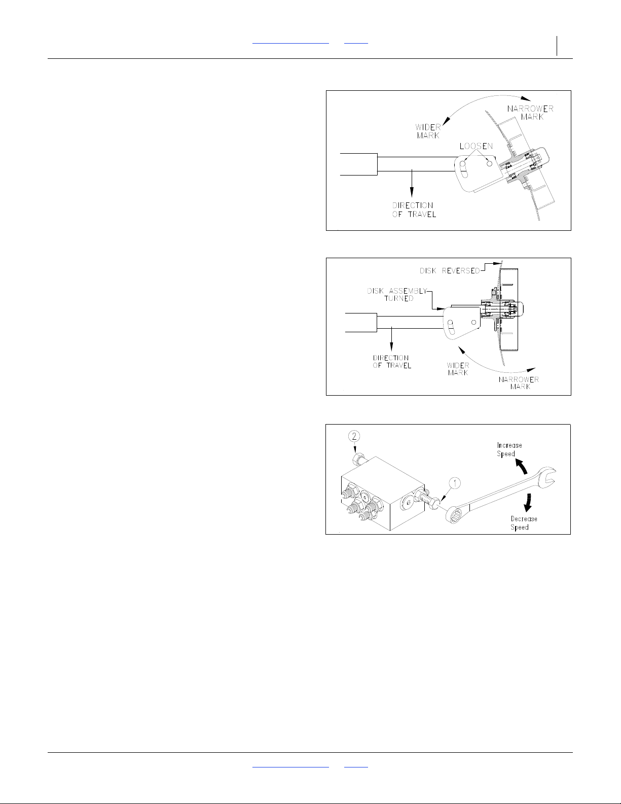
2N-2410 & 2N-3010 Table of Contents Index Adjustments 41
11757
Figure 27
Disc Angle
16403
Figure 28
Direction of Cut Reversed
14048
Figure 29
Speed Adjustment, Dual Markers
Disk Adjustment
The aggressiveness and the mark left by the disk may be
changed by two methods:
Angle of Cut
Refer to Figure 27
To change the angle of cut, loosen the two 1/2-inch bolts
holding the disk assembly. Rotate the disk assembly as
desired.
Direction of Cut
Refer to Figure 28
The disk may be mounted to throw dirt in or out for different
marks in different soil conditions. To change the direction of
cut:
a. Reverse the disk by removing the four lug bolts on
the disk hub. Remount the depth band and lug
bolts.
b. Turn the entire disk assembly by removing the two
1/2-inch bolts and turning the assembly one-half
turn. Reinstall the 1/2-inch bolts and set the disk
angle as desired.
Folding Speed
Refer to Figure 29
The dual markers are equipped with hex-head screws to
adjust folding speed. The screws are on the sequencevalve body. There are two screws–one controls folding
speed (1), the other controls unfolding speed (2). Turn the
adjustment screws clockwise for slower folding or
counterclockwise for faster folding. Adjust to a safe speed.
Excessive speed could damage the markers and void the
warranty.
8/2/18 Table of Contents Index 196-126M
Page 45
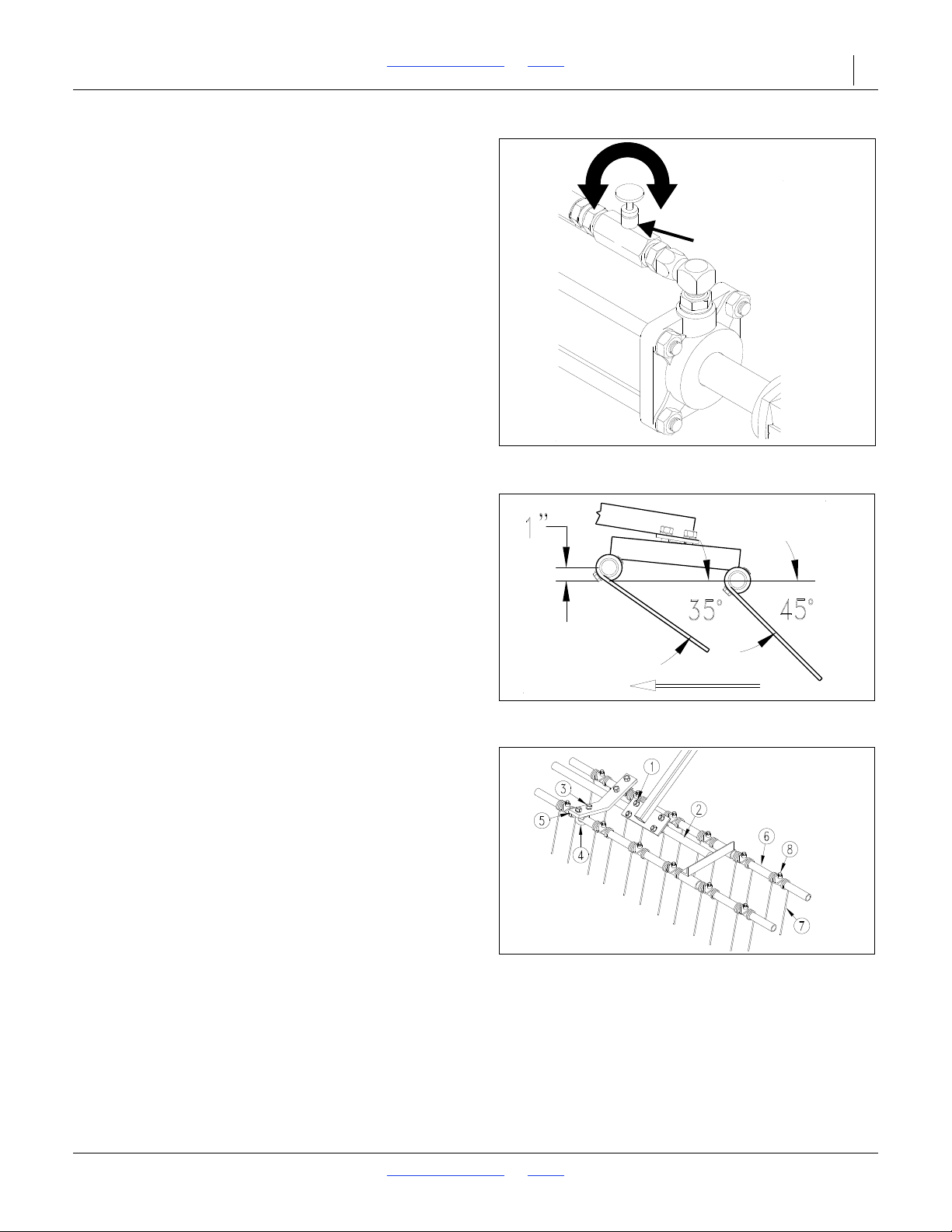
2N-2410 & 2N-3010 Table of Contents Index Adjustments 42
Faster
Slower
Needle Valve
15625
Figure 30
Speed Adjustment, Single Marker
12667
Figure 31
Tine Angle for No-Till Drilling
16297
Figure 32
Harrow Adjustment
Refer to Figure 30
The single-marker system is equipped with a needle valve
in the hydraulic hose line at the rod end of the marker
cylinder. Turn the adjustment knob clockwise to decrease or
counterclockwise to increase folding speed. Adjust to a safe
speed. Excessive folding speed could damage the marker
and may void the warranty.
Coulter Tines
Optional coulter tines are available for the front-mounted
coulters. In high-residue fields, the tines will help guide
residue under the coulters and openers to prevent plugging.
Under normal conditions these tines should not be needed.
Remove or install the tines as field condition warrant.
Harrow Attachment Adjustment
Refer to Figure 31
Figure 31 shows a successful harrow position for no-till
conditions. Because of different soil moisture, trash levels
and trash types, you may need to reposition the tube frame
or tines. Initially position the frame and tines as shown, then
re-adjust as necessary.
Refer to Figure 32
To adjust the frame, loosen the four hex nuts (1) on the ubolts and rotate the frame tube (2) as necessary.
To adjust the tines, loosen the four 1/2-inch hex nuts (3) on
the 1/2-inch U-bolts (4) on the support bar (5). Rotate tine
tubes (6) so the tines (7) are against the stop bushings (8)
and are angled back as necessary. Tighten hex nuts on
U-bolts.
Seed-Lok
The optional Seed-Lok firming wheels provide additional
seed-to-soil contact. The wheels are spring loaded and
do not require adjusting. In some wet and sticky
conditions the wheels may accumulate soil. Remove or
install the wheels as field conditions warrant.
8/2/18 Table of Contents Index 196-126M
Page 46
2N-2410 & 2N-3010 Table of Contents Index 43
Troubleshooting
Problem
Uneven seed
spacing
or stand
Opener disks not
turning freely
Actual seeding rate
is different than
desired
Excessive seed
cracking
Acremeter doesn’t
measure accurately
Uneven seeding
depth
Press wheel not
compacting the soil
as desired
Grain box not
emptying evenly
Solution
Check for plugging in seed cups.
Check for plugging in seed tubes.
Reduce ground speed.
Check that opener disks turn freely.
Shift speed-change gearbox to a faster drive-type and adjust the seed-rate handle to a lower number.
Increase spring pressure so openers penetrate low spots. Refer to Opener Down-Pressure
Adjustments, page 36.
Check for trash or mud build-up on Seed-Lok wheels.
Check for trash or mud build-up on disk scraper. Re-adjust scraper if necessary.
Refer to Disk Scraper Adjustment, page 39.
Check if disk scraper is restricting disk movement. Refer to Disk Scraper Adjustment, page 39.
Check disk bearings.
Check opener frame for possible damage.
If opener disks turn freely by hand but not in field, reduce down pressure on opener. Refer to Opener
Down-Pressure Adjustment, page 36.
Check if press wheels are adjusted too high. Refer to Press Wheel Adjustment, page 36.
Check tire pressure. Proper inflation is listed on Tire Inflation Chart, page 57.
Check gauge-wheel size. Proper size is 11L x 15 8-ply.
Clean seed-treatment build up out of seed cups and shafts.
Refer to Setting the Seeding Rate, page 37, for instructions on calculating seeding rate.
Use slower drive type on gearbox and adjust seed-rate handle to a higher number.
Position seed-cup doors to a lower notch. Refer to Set Seed-Cup Doors, page 38.
Check tire pressure. Proper inflation is listed on Tire Inflation Chart, page 57.
Check gauge-wheel tire size. Proper size is 11L x 15 8-ply.
Check seeding operation for excessive overlap or gaps between passes.
Consider soil conditions; loose soil and slippage will cause variations in acres registered.
Check that your acremeter is for your drill width. Refer to the parts manual.
Check if drill tongue is running level with ground. Refer to Hitch Height Adjustment, page 15.
Check if drill frame is level. Refer to Leveling Adjustment, page 39.
Reset press-wheel depth. Refer to Press Wheel Adjustment, page 36.
Re-adjust press wheel depth to match coulter depth.
Increase down-pressure on disk openers. Refer to Opener Down-Pressure Adjustment, page 36.
Check that speed-change gearbox and seed-rate handles are set the same on each drill box.
Certain models do not have the same number of seed cups between each divider of bulkhead.
The section with more cups will empty sooner.
8/2/18 Table of Contents Index 196-126M
Page 47

2N-2410 & 2N-3010 Table of Contents Index Troubleshooting 44
Problem
Press wheel or
openers plugging
Raising and
lowering drill is
rough or uneven
Seed-cup sprockets
locked up or twisted
seed-cup shaft
Coulters not going
deep enough
Coulters and drill
going too deep
Openers and/or
coulters plugging in
adverse conditions
Solution
Check soil conditions–may be too damp.
Decrease opener down pressure. See Opener Down-Pressure Adjustment, page 36.
Do not back up with openers in the ground.
Do not stop and allow drill to roll backward with openers in ground.
Check optional Seed-Lok wheels. Remove if soil conditions are too wet. Refer to Seed-Lok, page 42.
Install coulter trash tines. Refer to Coulter Tines,page 42.
Lubricate wheel-arm pivot casting. Refer to Lubrication, page 47.
Check hydraulic fittings for leaks.
Rephase the field-lift cylinders. Refer to Lifting the Drill in the Field, page 26.
Check that rephasing cylinders have been properly bleed. Refer to Field-Lift Hydraulics, page 17.
Check for foreign material lodged in one or more seed-cup sprockets.
Inspect seed-cups for dried liquid insecticide. Remove build-up by disassembling each seed cup and
scraping the foreign substance from the turning surfaces.
Check weight charts on page 33 and add weight if necessary.
Change depth stop to lower coulters. Refer to Coulter Adjustments, page 35.
Check weight charts on page 33 and remove weight if necessary.
Set press wheels to a shallower depth. Refer to Press Wheel Adjustment, page 36.
Change depth stop to raise coulters. Refer to Coulter Adjustments, page 30.
Drill at a slight angle to the rows.
Install coulter trash tines. Refer Coulter Adjustments page 30.
Actual seeding rate
is different than
desired
Hydraulic marker
functioning
improperly
Marker disk blade
does not mark
Check tire pressure. Proper inflation is listed on Tire Inflation Chart, page 57.
Check gauge wheel size. Proper size is 11L x 15" 8-ply.
Seed treatment will affect seeding rate if the chemicals build up in seed cup. Unless cleaned regularly,
this build-up can cause the seed-cup shaft to twist or break.
Check all hose fittings and connections for air and oil leaks.
Check that the chain on the folding marker is slack when the marker is both fully folded and unfolded.
Add chain slack as necessary. Refer to Marker Adjustments, page 40.
Check tractor hydraulic oil level.
Check all bolts and fasteners.
Check if needle valve is plugged; open valve, cycle markers, and reset the needle valve if necessary.
Check that switches on control console are set properly. Refer to Field Operations, page 26.
Check if the marker folding linkage and chain have enough slack to allow the marker disk to drop in low
spots. Maximum down float should be limited by the slots at the rod end of the marker cylinder–not by
the chain. Add chain slack as necessary. Refer to Marker Chain, page 40.
Reverse blade to pull dirt in or throw dirt out depending on soil conditions. Refer to Disc Scraper
Adjustment, page 39.
An optional smooth blade is available through your Great Plains dealer.
8/2/18 Table of Contents Index 196-126M
Page 48

2N-2410 & 2N-3010 Table of Contents Index Troubleshooting 45
Some chemicals will cause serious burns, lung damage and
death. Avoid contact with skin or eyes. Wear proper protective
equipment as required by chemical manufacturer. Avoid
prolonged breathing of chemical fumes. Wear respirator as
required by chemical manufacturer. Seek medical assistance
immediately if accident occurs. Know what to do in case of an
accident.
You may be severely injured or killed by being crushed from a
falling implement. Always have transport locks in place and
frame sufficiently blocked up when working on implement.
Escaping fluid under pressure can have sufficient pressure to
penetrate the skin. Check all hydraulic lines and fittings before
applying pressure. Fluid escaping from a very small hole can
be almost invisible. Use paper or cardboard, not body parts,
and wear heavy gloves to check for suspected leaks. If injured,
seek medical assistance from a doctor that is familiar with this
type of injury.
General Maintenance
Proper servicing and adjustment is the key to long
implement life. With careful and systematic inspection,
you can avoid costly maintenance, downtime and
repair. Always turn off and remove the tractor key
before making any adjustments or performing
maintenance.
1. After using your drill for several hours, check all
bolts to be sure they are tight. Periodically check
and secure all bolts, pins and fasteners. Tighten as
specified on Torque Values Chart, page 57.
2. Clean or replace any fittings that will not take
grease. Lubricate the drill as noted under
Lubrication, page 47.
3. Clean nozzles on optional rear-mount boom with a
low pressure (less than 30 psi) air hose.
Periodically replace nozzles. Always wear rubber
gloves when making repairs or adjustments.
4. Adjust idlers to remove excess slack from chains.
Adjust gauge-wheel arm drive chain as explained
under Gauge-Wheel Drive Adjustment, page 39.
Clean and use chain lube on all roller chains as
needed.
5. Always maintain correct tire pressure. Refer to Tire
Inflation Chart, page 57.
6. Occasionally inspect hydraulic hoses for cuts,
cracks and aging. Check fittings and cylinders for
evidence of leaks.
7. Check disk scrapers for proper adjustment. Refer to
Disk-Scraper Adjustment, page 39.
8. Replace any worn, damaged or illegible safety
labels at once. Refer to Safety Decals, page 5, for
correct label placement. Obtain new labels from
your Great Plains dealer.
8/2/18 Table of Contents Index 196-126M
Page 49
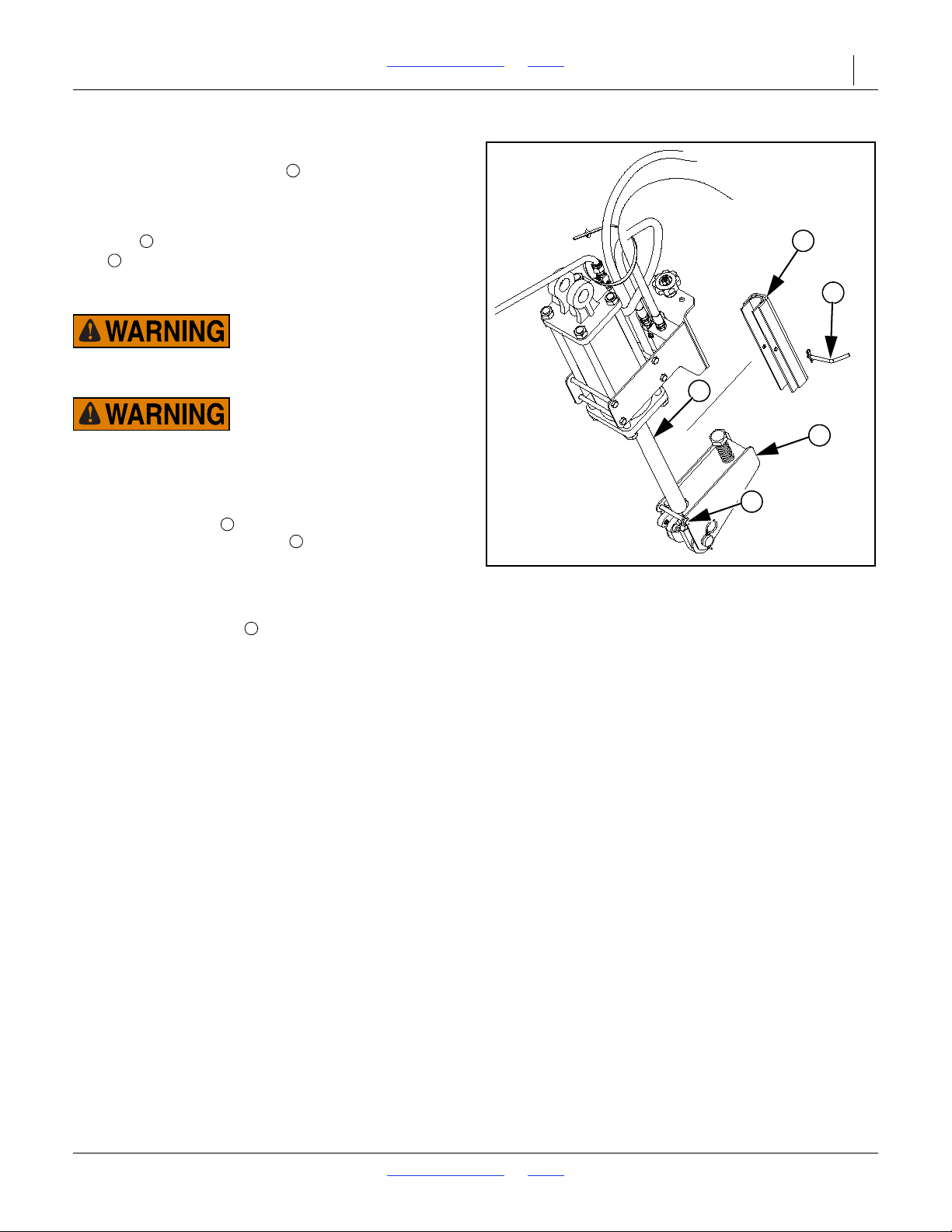
2N-2410 & 2N-3010 Table of Contents Index Troubleshooting 46
1
5
2
3
4
Figure 33
Pull Cable
1
12345
Cylinder Lock Channels
The cylinder lock channels are 1 1/2 in wide
channels. They are pinned to the bottom edges of the
mainframe near the tongue, one on each side. When
performing maintenance operations, the cylinder lock
channels must be installed on the field-lift cylinder
rods . During transport the cylinder lock channels
must be installed in the storage location on the
mainframe.
The cylinder lock channel must not contact the lower depth
stop assembly or damage will occur.
The cylinder lock channels must not be installed on the
field-lift cylinder rods during transport or damage can occur.
To install a cylinder lock channel on the left-hand
transport cylinder, do the following:
1. Remove the bolt , lock washer, and nut from the
lower depth stop assembly .
2. Rotate the lower depth stop assembly down.
3. Install the cylinder lock channel on the transport
cylinder rod.
4. Install the clevis pin and hair pin in the cylinder
lock channel.
Storage
Store the drill where children do not play. If possible,
store the drill inside for longer life.
1. If you store the drill in the unfolded position, unpin
and fully retract the fold cylinders to prevent rust.
2. Clean the drill as necessary. Be sure that the seed
boxes are cleaned completely before storing.
3. Disconnect seed hoses from openers. Premature hose
damage will occur if drill is stored with hoses connected.
4. Adjust idlers to remove excess slack from chains.
Adjust gauge-wheel-arm drive chain as explained
under Gauge-Wheel Drive Adjustment, page 39. Clean
and use chain lube on all roller chains as needed.
5. Lubricate the drill at all points indicated under
Lubrication, this page.
sprocket is oiled before the drill is stored.
6. Check all bolts, pins, fitting and hoses. Tighten,
repair or replace parts as needed.
7. Check all moving and soil-contact parts for wear or
damage. Make notes of any parts needing repair.
8. Use Great Plains touch-up paint to cover scratches,
chips and worn areas to prevent rust.
Be sure the seed-cup drive
8/2/18 Table of Contents Index 196-126M
Page 50
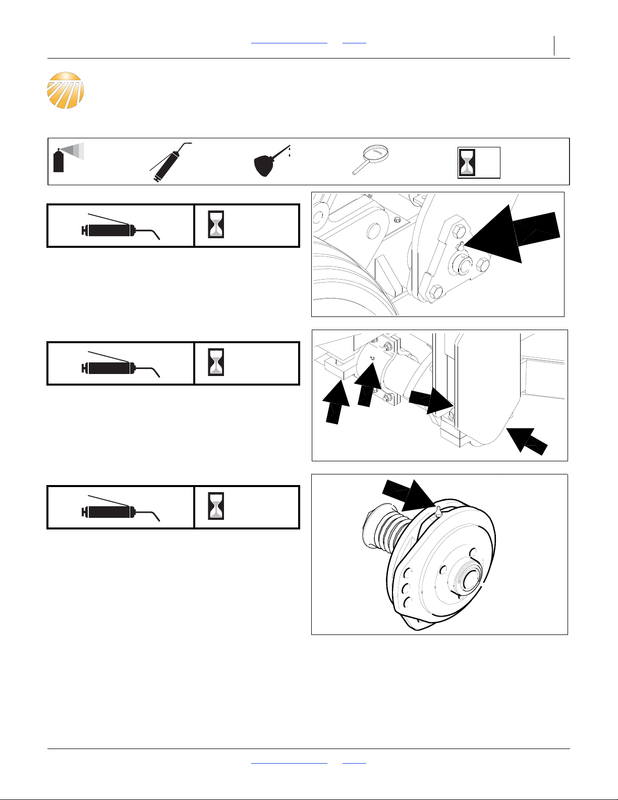
2N-2410 & 2N-3010 Table of Contents Index 47
50
Multi-purpose
spray lubricant
Multi-purpose
grease lubricant
Multi-purpose
oil lubricant
Intervals
(operating hours)
at which service
is required
Inspection
34208
12920
12921
12922
Lubrication
Gauge-Wheel-Arm Pivot Castings
8
The grease fittings are in the three-bolt cast bearings at
the end of each wheel arm pivot tube.
Type of Lubrication: Grease
Transport-Axle Assembly
8
Grease fittings on both sides of the three bearings
shown on each end of rockshaft - 12 fittings total.
(Rockshaft is inside and above the dual transport tires.)
Type of Lubrication: Grease
Clutches
8
Two zerks on each clutch (on models prior to 2002).
Type of Lubrication: Grease
8/2/18 Table of Contents Index 196-126M
Page 51
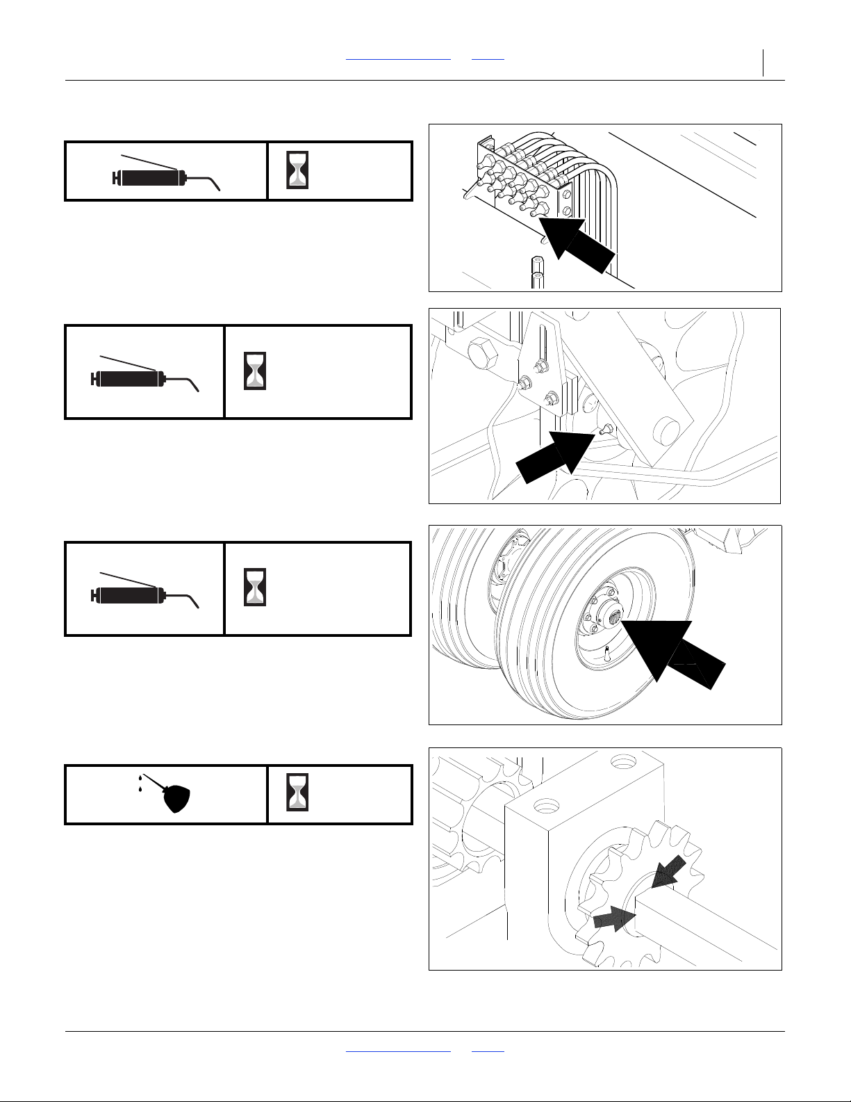
2N-2410 & 2N-3010 Table of Contents Index Lubrication 48
14192
12924
12926
12126
Coulter-Arm Pivots
8
Zerks are on central grease banks - two banks on each
box.
Type of Lubrication: Grease
Coulter Hub Bearings
Seasonal
ly
Type of Lubrication: Grease
Wheel Bearings
Seasonal
ly
Repack and check seals on transport and gauge
wheels.
Type of Lubrication: Grease
Seed-Cup-Drive Sprocket
10
Oil sprocket hub in its square bore. Squirt oil on the
square seed-cup shaft and move seed-rate handle
back and forth to get oil back into the square.
Type of Lubrication: Oil
8/2/18 Table of Contents Index 196-126M
Page 52
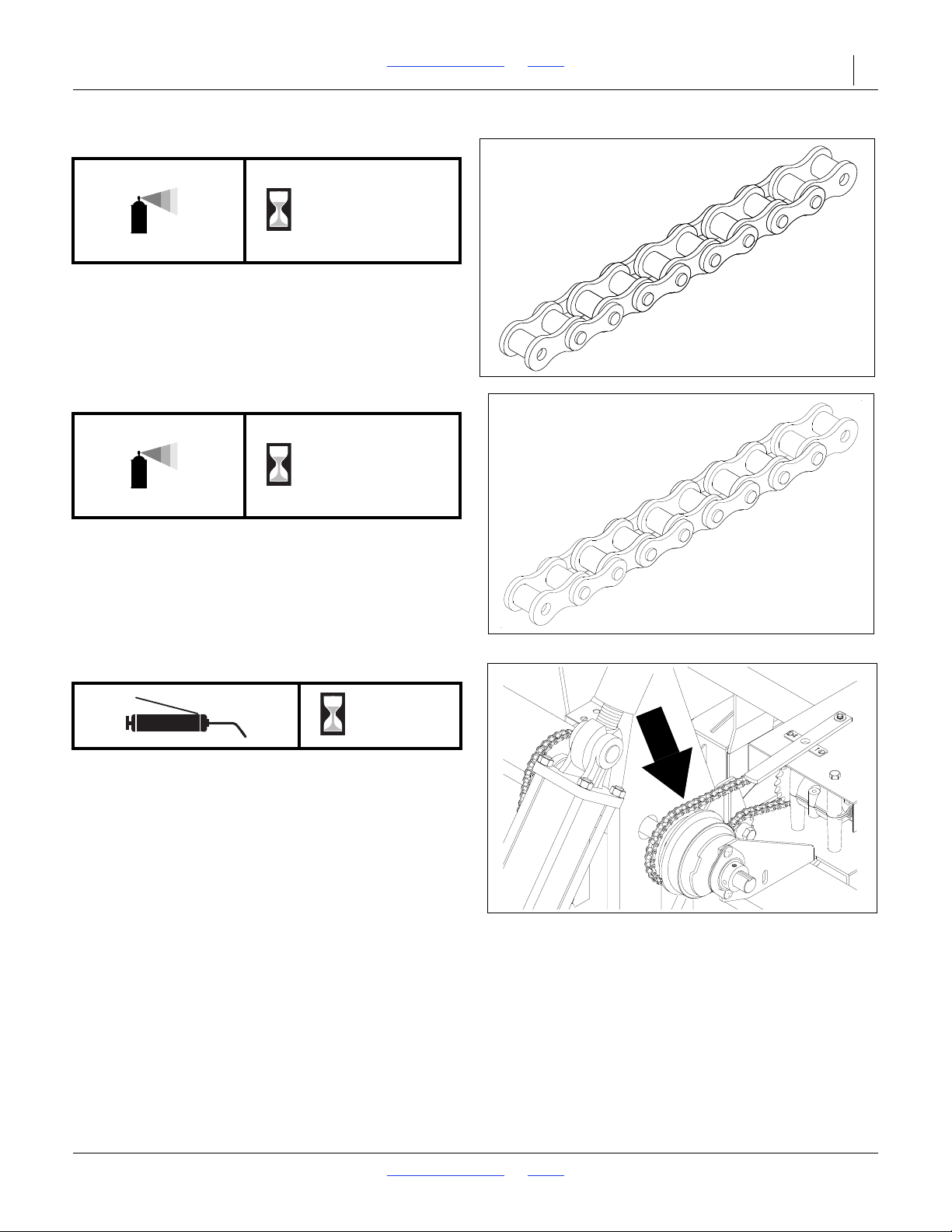
2N-2410 & 2N-3010 Table of Contents Index Lubrication 49
12227
12227
13933
Drive-TrainRoller Chain
As
Required
Type of Lubrication: Chain Lube
Optional Attachments Lubrication
Gauge-Wheel-to-Agitator Chains
As
Required
Type of Lubrication: Chain Lube
ElectricClutch-Drive Chain
Type of Lubrication: Chain Lube
15
8/2/18 Table of Contents Index 196-126M
Page 53
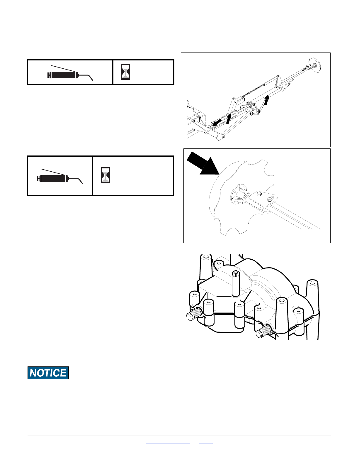
2N-2410 & 2N-3010 Table of Contents Index Lubrication 50
13008
12436
12167
Marker Hinges
25
Type of Lubrication: Grease
Marker-Disc Bearings
2 - 3
Years
If the grease seal cap is damaged or missing,
disassemble and clean the hub. Repack with grease
and install a new seal or grease cap.
Type of Lubrication: Grease
Speed-Change Box
The speed-change gearbox is lubricated and sealed at
the factory. Under normal conditions, it does not require
maintenance or lubrication.
If you open the gearbox for repair, repack all gears and
around the shaft bearings with least 7 ounces of
lithium-based, wheel-bearing grease.
It is important to keep moisture and dirt out of the
gearbox. Inspect the rubber seals on the gearbox drive
and shifter shafts. Replace seals if necessary.
Before bolting them back together, spread a very thin
coat of anaerobic sealant (such as Loctite 525) on the
gearcase-mating surfaces.Grease fittings on both sides
of the three bearings shown on each end of rockshaft 12 fittings total. (Rockshaft is inside and above the dual
transport tires.)
Use sealant sparingly! Excess sealant may squeeze off
surface and lock bearings or gears.
8/2/18 Table of Contents Index 196-126M
Page 54
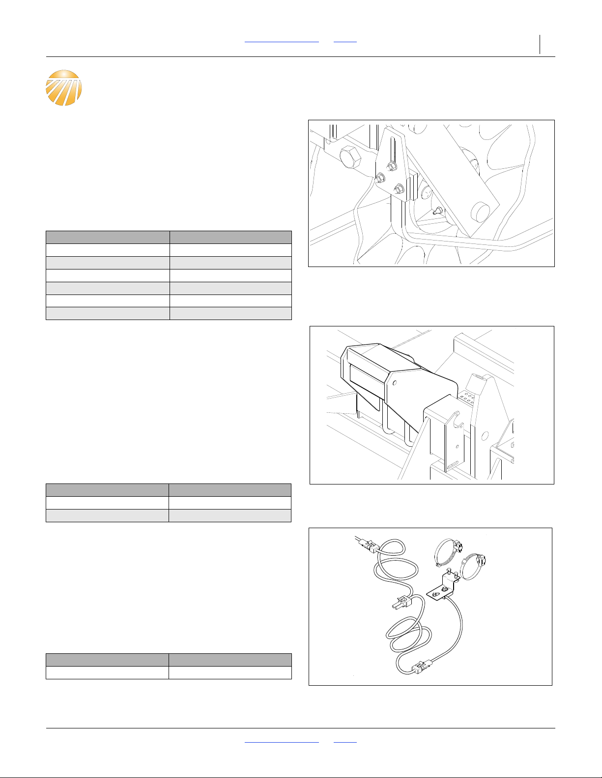
2N-2410 & 2N-3010 Table of Contents Index 51
12924
13011
13178
Options
Coulter Tines
The coulters on your implement can be equipped with
optional trash tines. Under most conditions, these tines
will not be needed. In high-residue fields, the tines will
help guide the residue under the coulters and openers
to prevent plugging.
To order tines, contact your Great Plains dealer. Refer
to the table below for the correct tine package for your
drill.
Drill Size Coulter Tine Part Number
24-ft., 7 1/2-in. Rows 149-717A
24-ft., 8-in. Rows 149-718A
24-ft., 10-in. Rows 149-719A
30-ft., 7 1/2-in. Rows 149-714A
30-ft., 8-in. Rows 149-715A
30-ft., 10-in. Rows 149-716A
Weight Brackets
If soil conditions require more weight for coulter
penetration, weight bracket kits are available. Each kit
contains two weight brackets–one for each box frame.
The weight brackets hold several styles of suitcase
weights commonly available through tractor dealers,
including John Deere, CASE, International Harvester
and CASE-IH.
For information on how additional weights will affect
seeding depth, refer to Weights, page 33.
To order weight brackets, contact your Great Plains
dealer. Refer to the table below for the correct brackets
for your drill.
Drill Size Weight Bracket Kit Part
24-ft. Drills 197-112A
30-ft. Drills 197-110A
Shaft Monitors
The optional 2-channel shaft monitor is an electronic
monitoring system to detect when seed-cup shafts stop
turning. If a shaft stops for more than 20 seconds, an
alarm sounds and a warning light designates the failed
shaft.
For information on how to operate the shaft monitors,
refer to Shaft Monitor Operation, page 28.
To order shaft monitors, contact your Great Plains
dealer.
Monitor Bundle Part Number
Shaft Monitor Package 197-106A
Specification Drawing
8/2/18 Table of Contents Index 196-126M
Page 55
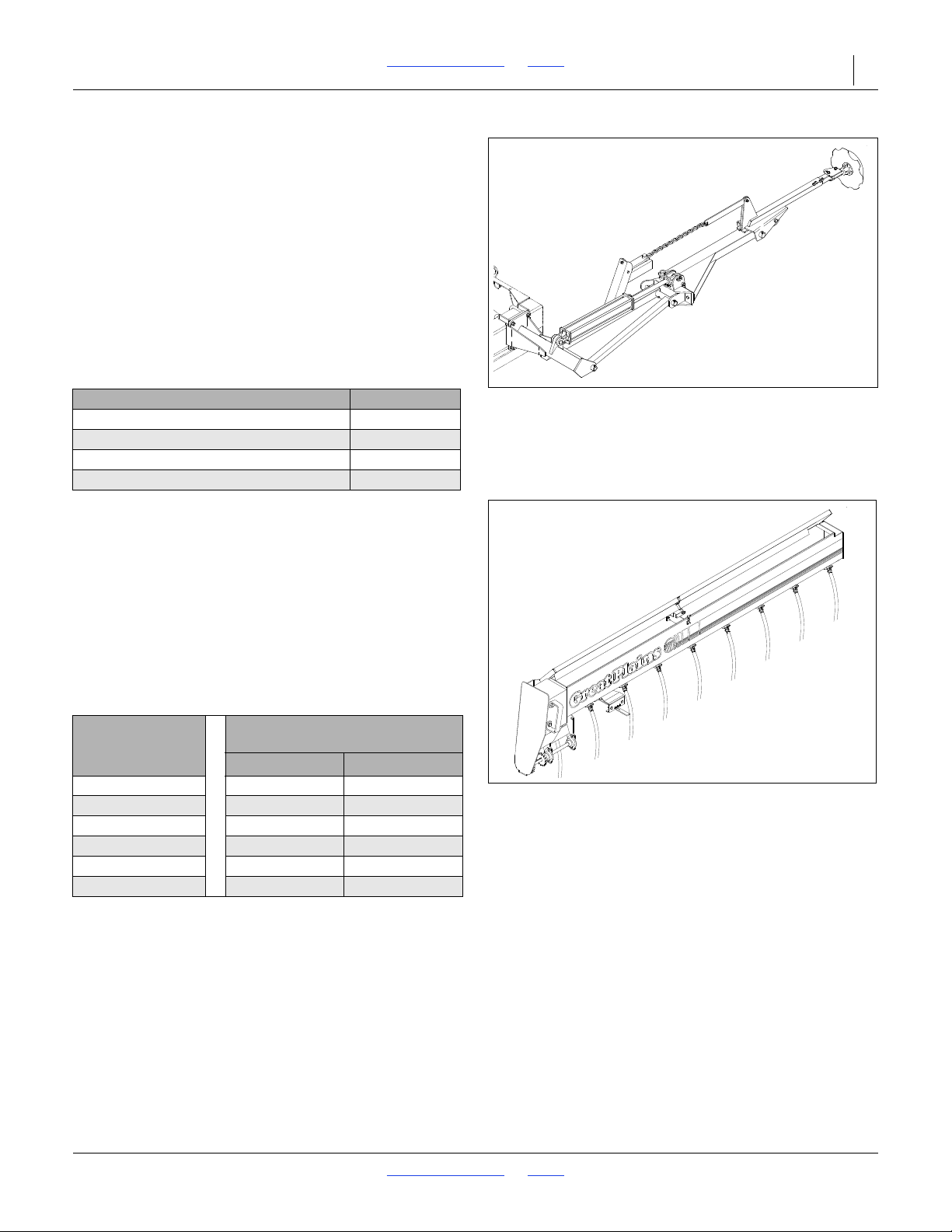
2N-2410 & 2N-3010 Table of Contents Index Options 52
13008
13734
Markers
Hydraulically operated no-till markers are available. The
units have a cast hub, tapered roller bearings and a bolton notched blade to cut though heavy residue, leaving a
line for you to follow on the next field pass. Markers are
sold as either a single or dual units. Dual markers are
equipped with a sequence valve for easy operation.
For information on how to operate the markers, refer to
Marker Operation, page 27. For information on how to
adjust the markers, refer to Marker Adjustment, page 40.
To order markers, contact your Great Plains dealer. Refer
to the table below for the correct marker package for your
drill
.
Marker Package Part Number
24-ft. 2-Section No-Till Left-Hand Flat-Fold 113-498A
24-ft. 2-Section No-Till Dual Flat-Fold 113-499A
30-ft. 2-Section No-Till Left-Hand Flat-Fold 113-500A
30-ft. 2-Section No-Till Dual Flat-Fold 113-501A
Small Seeds Attachment
The small-seeds attachment delivers the smallest
seeds evenly and gently. With a Y-tube, small seeds are
placed through the opener seed tube. Otherwise, seeds
are placed directly in front of the press wheel. The
attachment holds 0.24 bushels per foot.
For setting the seeding rate on the attachment, refer to
Check Seeding Rate page 38.
To order the small seeds attachment, contact your
Great Plains dealer. Refer to the table below for the
correct part number for your drill.
Attachment Package
Drill Size
With Y-Tube Without Y-Tube
24-ft., 7 1/2-in. Rows 133-024A 133-123A
24-ft., 8-in. Rows 133-026A 133-025A
24-ft., 10-in. Rows 133-128A 133-127A
30-ft., 7 1/2-in. Rows 133-017A 133-018A
30-ft., 8-in. Rows 133-020A 133-019A
30-ft., 10-in. Rows 133-022A 133-021A
8/2/18 Table of Contents Index 196-126M
Part Number
Page 56
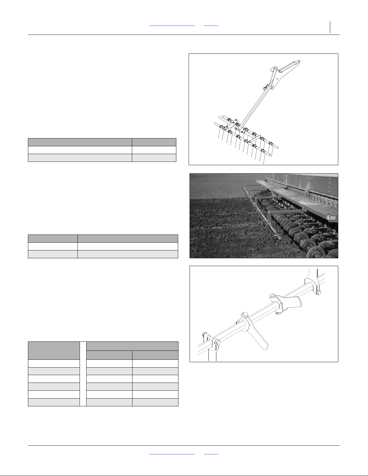
2N-2410 & 2N-3010 Table of Contents Index Options 53
13028
17996
12682
Harrow Attachment
The coil-tine harrow finishes no-till surfaces by leveling
and distributing residue for enhanced seed emergence.
The harrow attachment folds for transport.
For information on how to fold the harrow for transport,
refer to Folding Harrow Attachment, page 25. For
information on how to adjust the harrow, refer to Harrow
Attachment Adjustment, page 42.
To order the harrow attachment, contact your Great
Plains dealer.
Refer to the table below for the correct
harrow package for your drill.
Harrow Package Part Number
24-ft. No-Till Harrow Assembly 116-138A
30-ft. No-Till Harrow Assembly 116-137A
Rear Mount Boom
The drill boom mounts under the walkboard and allows
you to apply liquid herbicides or pesticides behind the
drill press wheels. The kit includes mounting hardware,
boom plumbing and nozzle bodies for 20-inch spacing.
Tractor tanks, pump, plumbing to the drill and nozzles
are required.
To order the boom, contact your Great Plains dealer.
Package Part Number
116-195A 24-Foot Two-Section No-Till Spray Boom
116-194A 30-Foot Two Section No-Till Spray Boom
Seed Box Agitator
An optional agitator can be added to the main seed
boxes. The agitator is designed to stir the seed directly
above the metering cups. The agitator helps prevent
bridging of light, fluffy seeds and separates soybeans
that are sticky with inoculant.
If your drill is equipped with a small seeds or fertilizer
attachment, the agitator is available without a drive.
To order the agitator, contact your Great Plains dealer.
Refer to the table below for the correct part for your drill.
Drill Size
24-ft., 7 1/2-in. Rows 118-459A 118-465A
24-ft., 8-in. Rows 118-460A 118-466A
24-ft., 10-in. Rows 118-461A 118-467A
30-ft., 7 1/2-in. Rows 118-456A 118-462A
30-ft., 8-in. Rows 118-457A 118-463A
30-ft., 10-in. Rows 118-458A 118-464A
Agitator Part Number
With Drive Without Drive
8/2/18 Table of Contents Index 196-126M
Page 57
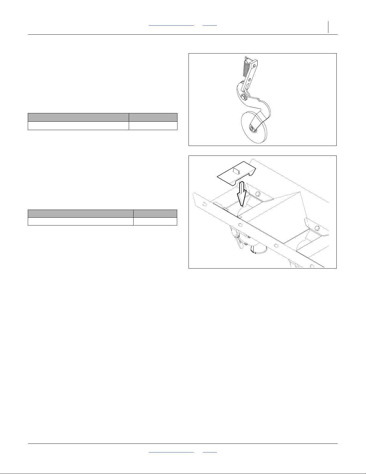
2N-2410 & 2N-3010 Table of Contents Index Options 54
12677
15642
Seed-Lok Firming Wheels
The optional, spring-loaded Seed-Lok firming wheel
presses the seed directly into the bottom of the seed
bed. The Seed-Lok option provides more even seed
emergence since seeds are planted and firmed at the
same depth.
To order Seed-Lok firming wheels, contact your Great
Plains dealer.
Seed-Lok Bundles Part Number
Solid Stand Removable 5-in. Seed-Lok 122-193k
Seed-Cup Plugs
Seed-cup plugs are available to block off individual
rows when you want wider row spacing. These plugs
are installed by pushing them into the seed-cup
openings on the desired rows.
To order seed-cup plugs, contact your Great Plains
dealer.
Seed Cup Plugs Package Part Number
1 3/4 in. Wide Seed-Cup Plug 817-087C
8/2/18 Table of Contents Index 196-126M
Page 58
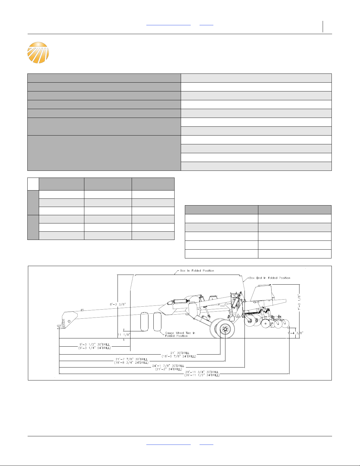
2N-2410 & 2N-3010 Table of Contents Index 55
Specifications and Capacities
Transport Width 17 feet, 1 inch
Working Width 24 or 30 feet
Box Length 12 or 15 feet
Dual Transport Tire Size 12.5L x 15 20-Ply
Gauge Wheel Tire Size: 11L x 15 8-Ply
Box Capacity:
Negative Tongue Weight:
24-ft. Drill: 48 bushels
30 ft. Drill: 60.6 bushels
24-ft. Drill, empty: 2650 lb.
24-ft. Drill, loaded: 3800 lb.
30-ft. Drill, empty: 2750 lb.
30-ft. Drill, loaded: 4000 lb.
Drill Row Number of
7.5 in.
8 in.
10 in.
24 ft.
7.5 in.
8 in.
10 in.
30 ft.
38 17,400 lb.
36 17,100 lb.
28 16,000 lb.
48 20,100 lb.
44 19,600 lb.
36 18,400 lb.
Drill Weight
All tires are warranted by the original manufacturer of
the tire. Tire warranty information can be found in the
brochures included with your Operator’s and Parts
Manuals or online at the manufacturer’s websites.
For service assistance or information, contact your
nearest Authorized Farm Tire Retailer.
Manufacturer Website
Titan www.titan-intl.com
Goodyear www.goodyearag.com
Firestone www.firestoneag.com
BKT Tires www.bkt-tires.com
Gleason Wheel www.gleasonwheel.com
8/2/18 Table of Contents Index 196-126M
Page 59
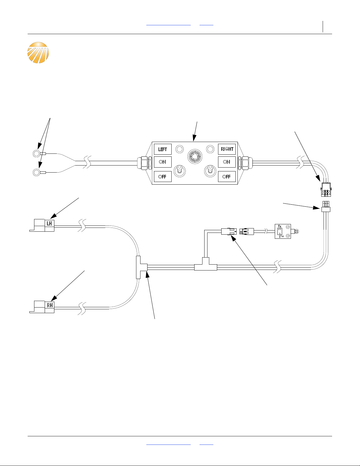
2N-2410 & 2N-3010 Table of Contents Index 56
Connect to tractor
battery.
Leave console loose
in the tractor cab.
Run this wire connector
out the cab and to the
back of the tractor.
At the front of the drill tongue, uncoil
the wire harness and connect the
plug to the plug coming from the
tractor cab.
Connect to the electric clutch
located on the left-hand side of
the frame.
Connect to the electric clutch
located on the right-hand side
of the frame.
Connect to the electric clutch switch
located on the left-hand gauge wheel
rockshaft.
At the rear of the tongue, uncoil the
wire harness and route appropriate
leads along the drill frame.
21790
Appendix
Electric Clutch Console and Wire Harness
8/2/18 Table of Contents Index 196-126M
Page 60
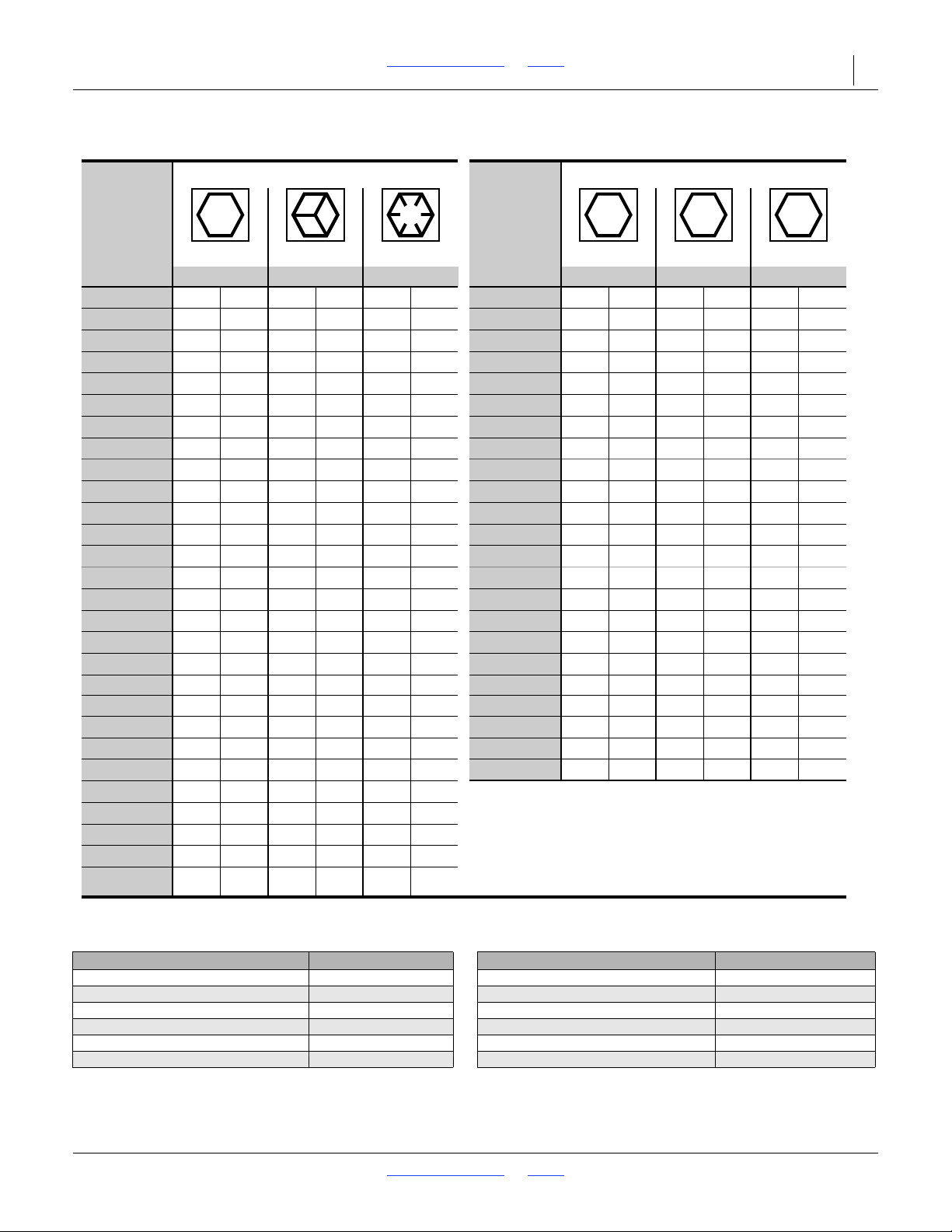
2N-2410 & 2N-3010 Table of Contents Index Appendix 57
946
25199m
Bolt
Size
Bolt Head Identification
Bolt
Size
Bolt Head Identification
Grade 2 Grade 5 Grade 8 Class 5.8 Class 8.8 Class 10.9
in-tpi
a
N-m
b
N-m N-m
mm x pitch
c
N-m N-m N-m
1
e4-20
7.4 11
M 5 X 0.8
1
e4-28
8.5 13 18
M 6 X 1
71115
5
e16-18
15 24 33
M 8 X 1.25
17 26 36
5
e16-24
17 26 37
M 8 X 1
18 2839
3
e8-16
27 42 59
M10 X 1.5
33 52 72
3
e8-24
314767
M10 X 0.75
39 61 85
7
e16-14
43 67 95
M12 X 1.75
5891 125
7
e16-20
49 75 105
M12 X 1.5
60 95130
1
e2-13
66 105 145
M12 X 1
90 105 145
1
e2-20
75 115 165
M14 X 2
92 145 200
9
e16-12
95 150 210
M14 X 1.5
99 155 215
9
e16-18
105 165 235
M16 X 2
145 225 315
5
e8-11
130 205 285
M16 X 1.5
155 240 335
5
e8-18
150 230 325
M18 X 2.5
195 310 405
3
e4-10
235 360 510
M18 X 1.5
220 350 485
3
e4-16
260 405 570
M20 X 2.5
280 440 610
7
e8-9
225 585 820
M20 X 1.5
310 650 900
7
e8-14
250 640 905
M24 X 3
480 760 1050
1-8
340 875 1230
M24 X 2
525 830 1150
1-12
370 955 1350
M30 X 3.5
960 1510 2100
1
1
e8-7
4801080 1750
M30 X 2
1060 16802320
1
1
e8-12
540 1210 1960
M36 X 3.5
1730 2650 3660
1
1
e4-7
680 1520 2460
M36 X 2
18802960 4100
1
1
e4-12
750 16802730
1
3
e8-6
8901990 3230
a. in-tpi = nominal thread diameter in inches-threads per inch
1
3
e8-12
1010 2270 3680
b. N· m = newton-meters
1
1
e2-6
1180 2640 4290
1
1
e2-12
13302970 4820
c. mm x pitch = nominal thread diameter in mm x thread pitch
To r que tolerance + 0%, -15% of torquing values. Unless otherwise specified use torque values listed above.
5.8
8.8
10.9
25199
ft-lb
d
ft-lb ft-lb ft-lb ft-lb ft-lb
5.6 8 12
61014 5 8 11
11 17 25 12 19 27
13 19 27 13 21 29
20 3144 2439 53
22 3549 29 45 62
3249 70 42 67 93
365578 44 70 97
49 76 105 66 77 105
55 85 120 68 105 150
70 110 155 73 115 160
79 120 170 105 165 230
97 150 210 115 180 245
110 170 240 145 230 300
170 265 375 165 260 355
190295 420 205 325 450
165 430 605 230480 665
185 475 670 355 560 780
250 645 910 390 610 845
275 705 99
5 705 1120 1550
355 7951290785 1240 1710
395 890 1440 1270 1950 2700
500 1120 1820 13802190 3220
555 1240 2010
655 1470 2380
745 1670 2710
870 1950 3160
d. ft-lb = foot pounds
9802190 3560
3 57
Torque Values Chart for Common Bolt Sizes
Tire Inflation Chart
Tire Size Inflation PSI Tire Size Inflation PSI
9.0 x 22.5 10-Ply Highway Service 70 70 11L x 15" 8-Ply Rib Implement 36
8/2/18 Table of Contents Index 196-126M
7.50 x 20" 4-Ply Drill Rib 28 11L x 15" 6-Ply Rib Implement 28
9.0 x 24" 8-Ply Rib Implement 40 12.5L x 15" 8-Ply Rib Implement 36
9.5L x 15" 6-Ply Rib Implement 32 12.5L x 15" 10-Ply Rib Implement 44
9.5L x 15" 8-Ply Rib Implement 44 12.5L x 15" 20-Ply Rib Implement 90
9.5L x 15" 12-Ply Rib Implement 60 41 x 15" x 18 - 22-Ply Rib Implement 44
Page 61
2N-2410 & 2N-3010 Table of Contents Index Appendix 58
38112
Warranty
Great Plains (a division of Great Plains Manufacturing, Inc.) warrants to the
original purchaser that this Great Plains unit will be free from defects in material
and workmanship for a period of one year from the first use date when used as
intended and under normal service and conditions for personal use; ninety days
for custom/commercial or rental use. This Warranty is limited to the replacement
of any defective part by Great Plains and the installation by the dealer of any
such replacement part. Great Plains reserves the right to inspect any equipment
or part which are claimed to have been defective in material or workmanship.
The following items and/or conditions are not covered under warranty:
failures resulting from abuse or misuse of the equipment, failures occurring as a
result of accidental damage or acts of God, failures resulting from alterations or
modifications, failures caused by lack of normal maintenance as outlined in the
operator’s manual, repairs made by non-authorized personnel, items replaced or
repaired due to normal wear (such as wear items and ground engaging
components), repeat repair due to improper diagnosis or repair by the dealer,
temporary repairs, service calls and/or mileage to and from customer location,
overtime premium, or unit hauling expenses. The warranty may be voided if the
unit is towed at speeds in excess of 20 miles per hour (32 kilometers per hour),
or is used in soils with rocks, stumps, or other obstructions.
Great Plains reserves the right to make changes in materials or design of the
product at any time without notice. The warranty shall not be interpreted to
render Great Plains liable for damages of any kind, direct or consequential or
contingent to property. Furthermore, Great Plains shall not be liable for damages
resulting from any cause beyond its control. This warranty does not extend to
crop loss, losses caused by planting or harvest delays or any expense or loss of
labor, supplies, rental machinery, or for any other reason.
No other warranty of any kind whatsoever express or implied, is made with
respect to this sale; and all implied warranties of merchantability and fitness for
a particular purpose which exceed the obligations set forth in this written
warranty are hereby disclaimed and excluded from this sale.
This warranty is not valid unless the unit is registered with Great Plains within
10 days from the date of the original purchase.
8/2/18 Table of Contents Index 196-126M
Page 62

2N-2410 and 2N-3010 Cover Table of Contents 59
Index
A
accident, hydraulic ................................2
acremeter, operation ..........................28
amber reflector .....................................7
C
CAUTION, defined ...............................1
chain, safety .........................................3
chemicals .............................................2
children .................................................3
clean-out ...............................................2
clothing .................................................2
containers .............................................2
D
DANGER, defined ................................1
daytime reflector ...................................6
decal replacement ................................5
decals
caution
general .................................10
lowering drill .........................10
no step .................................10
pressure and torque .............11
danger
chemical hazard .....................8
notice
no petroleum products .........12
warning
negative tongue weight ..........9
pinching/crushing ...................8
speed .....................................9
tongue weight .........................9
transport lock .........................8
decal, safety .........................................5
disposal ................................................2
F
fire ........................................................1
fumes....................................................4
H
headphones .......................................... 2
hearing .................................................2
High Pressure Fluids ............................2
L
leaks .....................................................2
lights .....................................................3
M
maintenance safety ..............................4
P
protective equipment ............................2
R
red reflector ..........................................6
reflector
amber............................................ 7
daytime ......................................... 6
red................................................. 6
SMV .............................................. 5
reflectors, safety................................... 5
riders .................................................... 3
S
safety chain .......................................... 3
safety decal .......................................... 5
safety information
decals ........................................... 5
safety symbol ....................................... 1
shutdown.............................................. 3
Slow Moving Vehicle ............................ 5
smoke .................................................. 2
SMV (Slow Moving Vehicle) ................. 5
storage ................................................. 3
symbol, safety ...................................... 1
T
tires ...................................................... 4
transport speed .................................... 3
U
URLs, tires ......................................... 55
W
WARNING, defined .............................. 1
welding ................................................. 4
Numerics
152-314M, manual ............................. 28
152-325M, manual ............................. 28
194-074M, manual ............................. 28
194-209M, manual ............................. 28
20 mph ................................................. 3
30 kph .................................................. 3
818-019C, decal................................... 9
818-020C, decal................................. 10
818-030C, reflector .............................. 6
818-04C,decal...................................... 8
818-055C, reflector .............................. 5
818-078C, decal................................. 10
818-188C, decal................................... 9
818-229C, reflector .............................. 7
818-398C, decal................................. 10
818-476C, decal................................... 9
818-477C, decal................................... 8
818-855C, decal................................. 11
818-860C, decal................................... 9
838-092C, decal...........................11
838-259C, decal................................. 12
838-265C, reflector .............................. 7
838-266C, reflector .............................. 6
838-267C, decal................................... 6
838-426C, decal................................. 11
, 12
838-467C, decal ...................................8
858-679C, decal .................................12
8/2/18 Cover Table of Contents 196-126M
Page 63

Table of Contents Index
Table of Contents Index
Page 64

Great Plains, Mfg.
1525 E. North St.
P.O. Box 5060
Salina, KS 67402
 Loading...