

Page 1
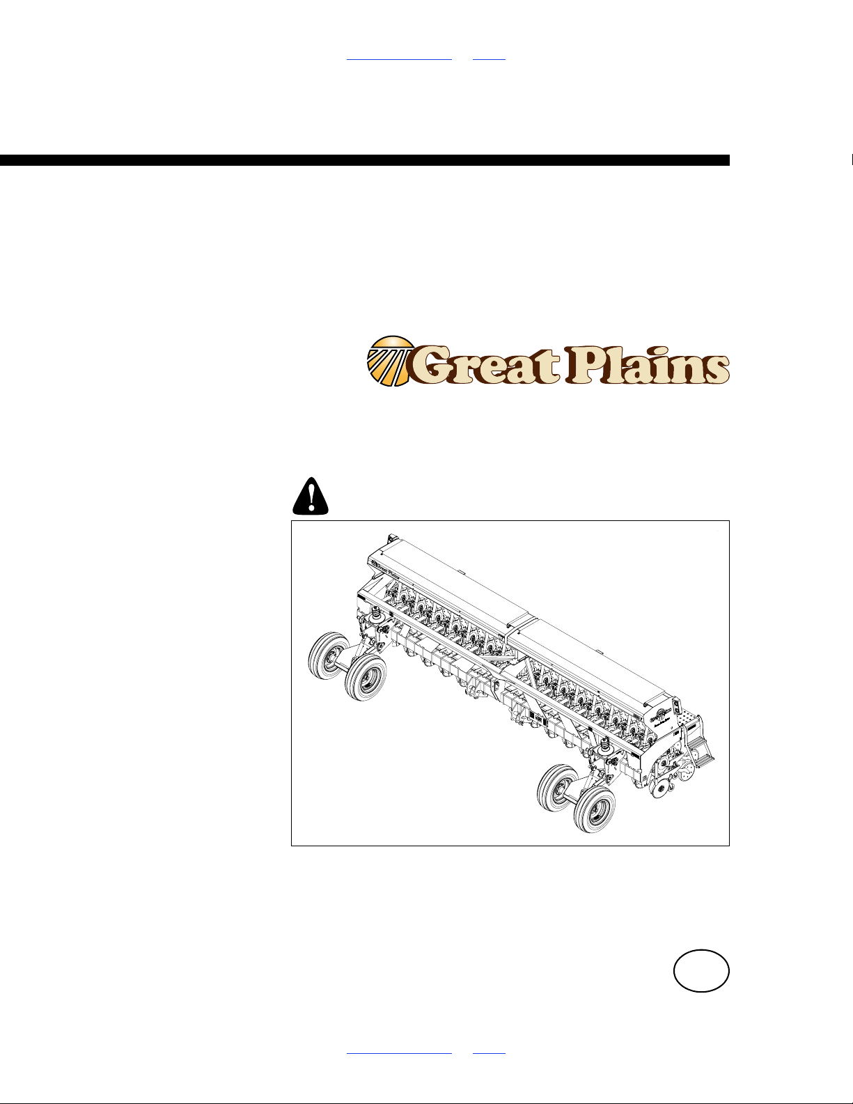
Table of Contents Index
27129
Operator Manual
1510HDP, 2010HDP and 2510HDP
15-, 20-, 25-Foot 3-Point Drills
with 10 Series Heavy Duty Precision Openers
Manufacturing, Inc.
www.greatplainsmfg.com
Read the operator manual entirely. When you see this symbol, the
subsequent instructions and warnings are serious - follow without
exception. Your life and the lives of others depend on it!
Illustrations may show optional equipment not supplied with standard unit or
may depict similar models where a topic is identical.
ORIGINAL INSTRUCTIONS
© Copyright 2018 Printed 2018-07-18 118-245M
Table of Contents Index
EN
Page 2
Machine Identification
Record your machine details in the log below. If you replace this manual, be sure to transfer this information to the new
manual.
If you or the dealer have added options not originally ordered with the machine, or removed options that were originally
ordered, the weights and measurements are no longer accurate for your machine. Update the record by adding the
machine weight and measurements with the option(s) weight and measurements.
Model Number
Serial Number
Machine Height
Machine Length
Machine Width
Machine Weight
Year of Construction
Delivery Date
First Operation
Accessories
Dealer Contact Information
Name:
Street:
City/State:
Telephone:
Email:
Dealer’s Customer
No.:
WARNING:
Cancer and Reproductive Harm - www.P65Warnings.ca.gov
Page 3

1510HDP, 2010HDP and 2510HDP Cover Index Table of Contents
Table of Contents
Important Safety Information.................................................1
Safety Reflectors and Decals ............................................5
Introduction...........................................................................10
Document Family.............................................................10
Description of Unit ...........................................................10
Intended Usage ........................................................10
Models Covered .......................................................10
Using This Manual...........................................................10
Owner Assistance............................................................11
Preparation and Setup .........................................................12
Pre-Setup Checklist.........................................................12
Hitching............................................................................12
20- and 25-foot Hitching ...........................................12
15-foot Hitching ........................................................13
Electrical Connections .....................................................14
Hydraulic Hose Hookup (Options) ...................................15
Older Style Hoses with Color Ties............................17
Leveling the Drill ..............................................................18
Leveling: Single-Wheel.............................................19
Leveling: Offset-Single Wheel..................................20
Leveling: Dual-Wheel ...............................................21
Options Setup..................................................................22
Acremeter Installation...............................................22
Seed Monitor Cab Module...............................................22
Speed Sensor Installation ........................................22
Hydraulic Console Installation .........................................23
Marker Setup ...................................................................24
Marker Chain Adjustment.........................................24
Marker Extension Setup ...........................................25
Marker Extension Adjustment ..................................25
Operating Instructions .........................................................26
Pre-Start Checklist...........................................................26
Prepare for Planting.........................................................26
Transporting ....................................................................27
Loading Materials ............................................................28
Seed Lubricants .......................................................29
Acremeter Operation .......................................................30
Normal Operating Sequence ...........................................30
Dormant Display ..............................................................30
Field Operation ................................................................31
Marker Operations...........................................................32
Independent Markers ...............................................32
Dual Auto-Sequenced Markers ................................32
Parking ............................................................................33
Storage ............................................................................33
Adjustments ..........................................................................34
Planting Depth.................................................................34
Material Rate Adjustments ..............................................35
Main Box Seed Rate ................................................36
Checking Main Box Seed Rate ................................38
Small Seeds Attachment Rate .................................42
Fertilizer Rate...........................................................45
Row Unit Adjustments .....................................................48
Unit-Mounted Coulter Adjustments ..........................49
Row Unit Down-Force ..............................................51
Row Unit Shutoff ......................................................53
Disk Blade Adjustments ...........................................57
Meter Adjustments ...................................................58
Seed Firmer Adjustments.........................................64
Press Wheel Adjustments ........................................65
Marker Adjustments ........................................................66
Marker Disk Angle....................................................66
Marker Speed...........................................................66
Hydraulic Drive Operation ...................................................68
Drive Operational Requirements .....................................68
Hydraulic System: ....................................................68
Electrical System:.....................................................68
Tractor Hookup................................................................68
Hydraulics: ...............................................................68
Electrical:..................................................................68
Controller Menu...............................................................69
Console Functions...........................................................70
Calibration .......................................................................70
Speed Calibration............................................................75
Operations.......................................................................77
Before going to the field ...........................................77
In Field .....................................................................77
Hydraulic Drive Calibration.......................................79
Varying Rates with Pre-set Function ...............................87
GPS-Based Planting .......................................................88
FarmWorks SiteMate ...............................................88
GP Precision Population Settings ............................88
Troubleshooting with SiteMate.................................89
Ag Leader PF3000 ...................................................90
Troubleshooting with PF3000 ..................................90
Hydraulic Drive Maintenance ..........................................92
To change the element: ...........................................92
Hydraulic Drive Troubleshooting .....................................93
Drive will not rotate:..................................................93
Drive rotates but not at desired speed: ....................94
Calibration Troubleshooting: ....................................95
Hydraulic Drive Troubleshooting Flow Chart...................96
© Copyright 2008, 2009, 2013, 2018 All rights Reserved
Great Plains Manufacturing, Inc. provides this publication “as is” without warranty of any kind, either expressed or implied. While every precaution has been
taken in the preparation of this manual, Great Plains Manufacturing, Inc. assumes no responsibility for errors or omissions. Neither is any liability assumed for
damages resulting from the use of the information contained herein. Great Plains Manufacturing, Inc. reserves the right to revise and improve its products as
it sees fit. This publication describes the state of this product at the time of its publication, and may not reflect the product in the future.
Registered Trademarks of Great Plains Manufacturing, Inc. include: Air-Pro, Clear-Shot, Discovator, Great Plains, Land Pride, MeterCone,
Nutri-Pro, Seed-Lok, Solid Stand, Terra-Guard, Turbo-Chisel, Turbo-Chopper, Turbo-Max, Turbo-Till, Ultra-Till, Whirlfilter, and Yield-Pro.
Trademarks of Great Plains Manufacturing, Inc. include: AccuShot, Max-Chisel, Row-Pro,
Singulator Plus, Short Disk, Swath Command, Terra-Tine, Ultra-Chisel, and X-Press.
Brand and Product Names that appear and are owned by others are trademarks of their respective owners.
Printed in the United States of America
Great Plains | 118-245M | 2018-07-18 Cover Index iii
Page 4

1510HDP, 2010HDP and 2510HDP Cover Index Table of Contents
Hydraulic Drive Electronics Troubleshooting...................97
Troubleshooting ...................................................................98
Maintenance and Lubrication............................................103
Materials Clean-Out.......................................................103
Main Seed Box Clean-Out......................................103
Small Seeds Box Clean-Out...................................103
Fertilizer Clean-Out ................................................104
Meter Maintenance........................................................105
Singulator Plus Meter Maintenance .......................105
Finger Meter Maintenance .....................................107
Row Unit Maintenance ..................................................109
Seed Tube Maintenance ........................................109
Grommet Maintenance...........................................109
Disk Spreader-Scraper...........................................110
Seed Flap Replacement.........................................110
Chain Maintenance........................................................111
Chain Slack ............................................................111
Idler Chain Tension ................................................111
Marker Maintenance......................................................112
Marker Shear Bolt ..................................................112
Marker Disk Grease Seal .......................................112
Bleeding Marker Hydraulics ...................................113
Marker Transport Carrier........................................114
Lubrication .....................................................................115
Options ................................................................................120
Accessory Hitches .........................................................120
Hitch Setback Kit ...........................................................120
Seed Monitor .................................................................121
Speed Sensors ..............................................................122
Hydraulic Meter Drive ....................................................123
Gauge Wheels...............................................................124
Weight Bracket Kit.........................................................124
Markers..........................................................................125
Seed Lubricants.............................................................125
Main Seed Box Baffles ..................................................126
Fertilizer.........................................................................127
Small Seeds ..................................................................128
Small Seed Tube Plugs .................................................128
Row Unit Options...........................................................129
10HD Series Seed Meters.............................................129
Row Unit Press Wheels.................................................131
Appendix .............................................................................132
Specifications and Capacities........................................132
Tire Inflation Chart .........................................................134
Torque Values Chart .....................................................135
Row Spacing Data.........................................................135
Hydraulic Diagrams .......................................................162
Chain Routing................................................................165
Warranty........................................................................168
Great Plains | 118-245M | 2018-07-18 Cover Index iv
Page 5
1510HDP, 2010HDP and 2510HDP Table of Contents Index Important Safety Information
Important Safety Information
Look for Safety Symbol
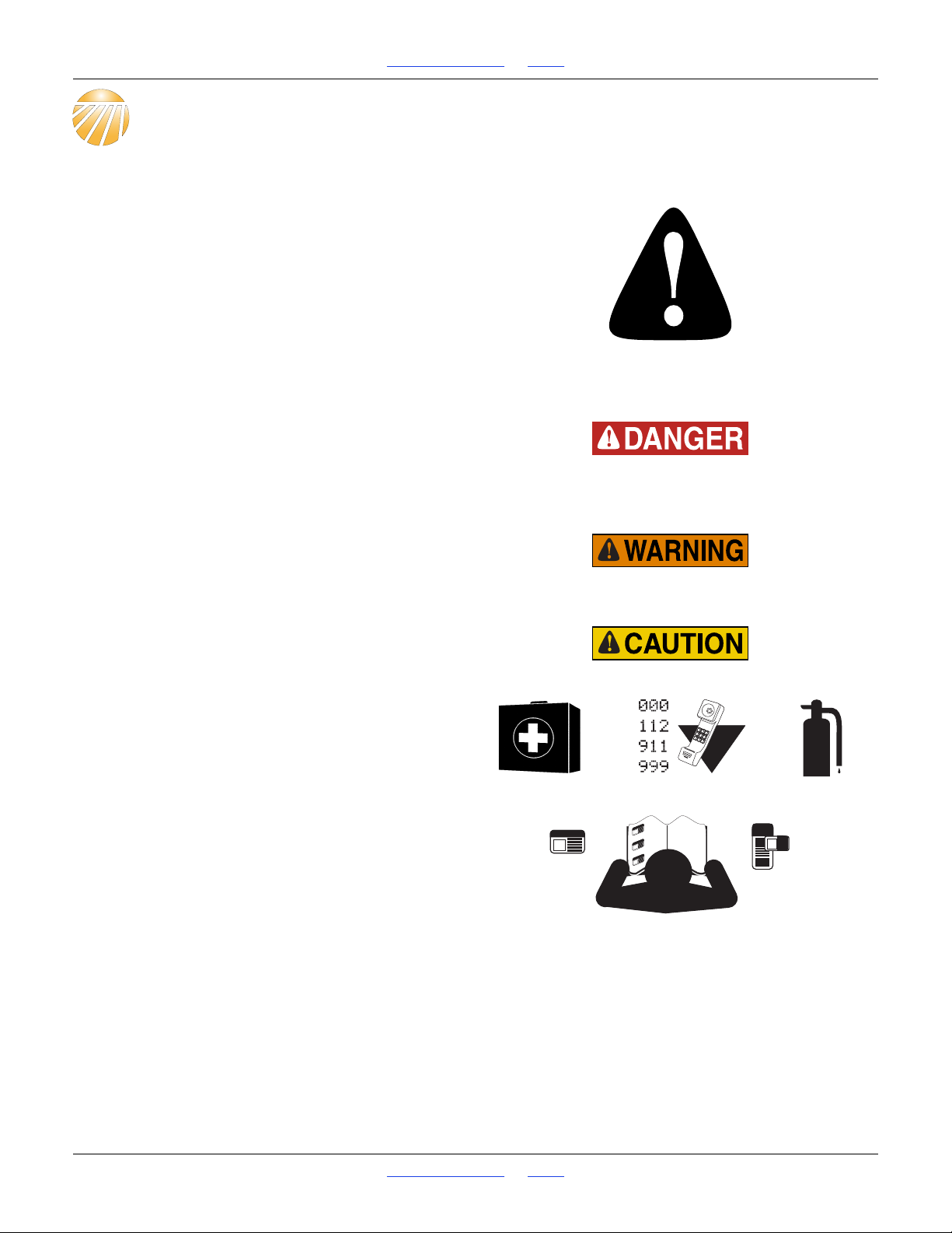
The SAFETY ALERT SYMBOL indicates there is a
potential hazard to personal safety involved and extra
safety precaution must be taken. When you see this
symbol, be alert and carefully read the message that
follows it. In addition to design and configuration of
equipment, hazard control and accident prevention are
dependent upon the awareness, concern, prudence and
proper training of personnel involved in the operation,
transport, maintenance and storage of equipment.
Be Aware of Signal Words
Signal words designate a degree or level of hazard
seriousness.
DANGER indicates an imminently hazardous situation
which, if not avoided, will result in death or serious injury.
This signal word is limited to the most extreme situations,
typically for machine components that, for functional
purposes, cannot be guarded.
WARNING indicates a potentially hazardous situation
which, if not avoided, could result in death or serious
injury, and includes hazards that are exposed when
guards are removed. It may also be used to alert against
unsafe practices.
CAUTION indicates a potentially hazardous situation
which, if not avoided, may result in minor or moderate
injury. It may also be used to alert against unsafe
practices.
Prepare for Emergencies
Be prepared if a fire starts
Keep a first aid kit and fire extinguisher handy.
Keep emergency numbers for doctor, ambulance, hospital
and fire department near phone.
Be Familiar with Safety Decals
Read and understand “Safety Reflectors and Decals”
starting on page 5, thoroughly.
Read all instructions noted on the decals.
Keep decals clean. Replace damaged, faded and illegible
decals.
Great Plains | 118-245M | 2018-07-18 Table of Contents Index 1
Page 6
1510HDP, 2010HDP and 2510HDP Table of Contents Index Important Safety Information
Avoid High Pressure Fluids
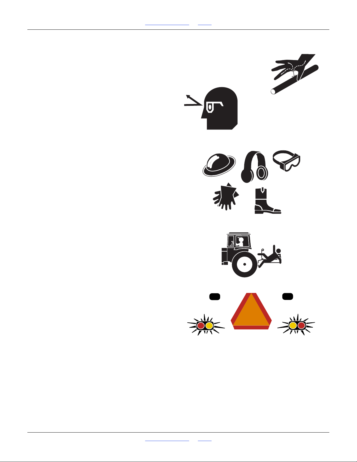
Escaping fluid under pressure can penetrate the skin,
causing serious injury.
Avoid the hazard by relieving pressure before
disconnecting hydraulic lines.
Use a piece of paper or cardboard, NOT BODY PARTS, to
check for suspected leaks.
Wear protective gloves and safety glasses or goggles when
working with hydraulic systems.
Hydraulic fluid injected under the skin is an extremely
serious matter. If such an accident occurs, seek urgent
medical attention from a physician familiar with this type
of injury.
Wear Protective Equipment
Wear protective clothing and equipment.
Wear clothing and equipment appropriate for the job.
Avoid loose-fitting clothing.
Because prolonged exposure to loud noise can cause
hearing impairment or hearing loss, wear suitable
hearing protection such as earmuffs or earplugs.
Because operating equipment safely requires your full
attention, avoid wearing entertainment headphones while
operating machinery.
Keep Riders Off Machinery
Riders obstruct the operator’s view. Riders could be
struck by foreign objects or thrown from the machine.
Never allow children to operate equipment.
Keep all bystanders away from machine when
folding/unfolding, raising/lowering markers,
raising/lowering openers, and transporting.
Use Safety Lights and Devices
Slow-moving tractors and towed implements can create
a hazard when driven on public roads. They are difficult
to see, especially at night.
Use flashing warning lights and turn signals whenever
driving on public roads.
Use lights and devices provided with the drill.
Great Plains | 118-245M | 2018-07-18 Table of Contents Index 2
Page 7
1510HDP, 2010HDP and 2510HDP Table of Contents Index Important Safety Information
Transport Machinery Safely
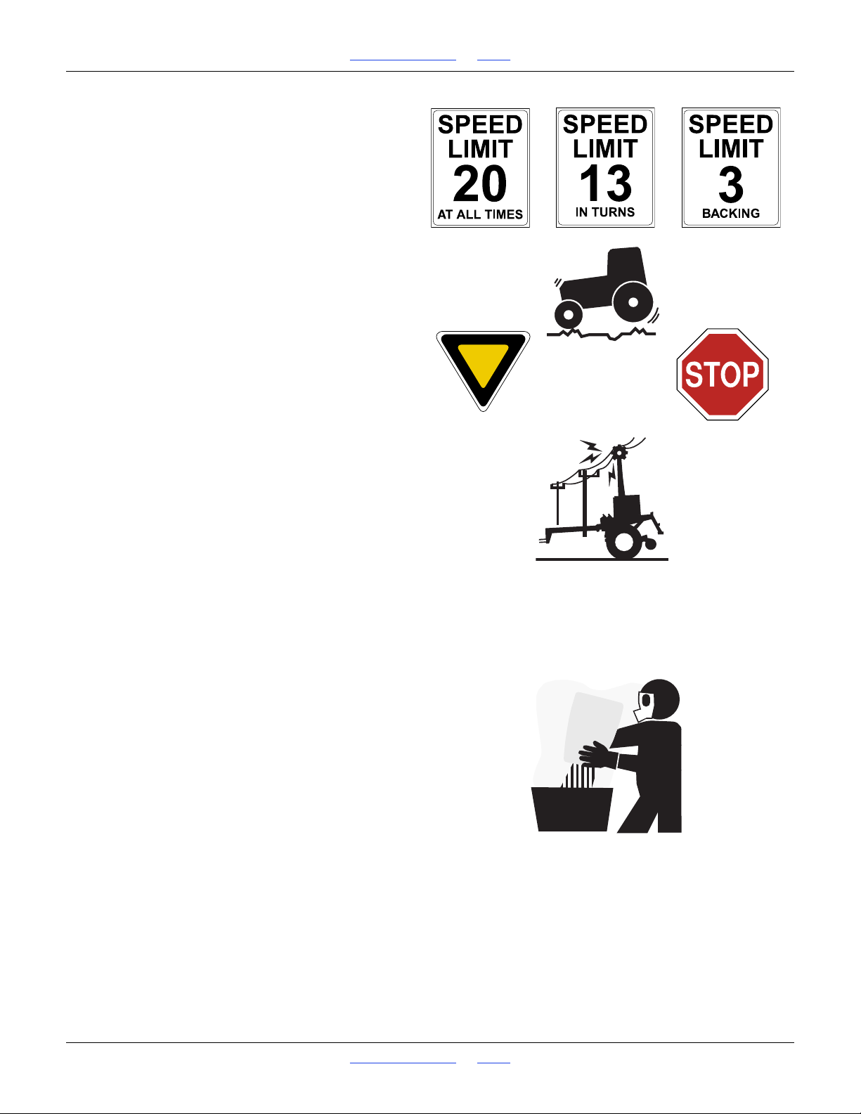
Maximum transport speed for drill is 20 mph (32 kph).
Some rough terrains require a slower speed. Sudden
braking can cause a towed load to swerve and upset.
Do not exceed 20 mph (32 kph) or the legal speed limit,
whichever is lower. Never travel at a speed which does not
allow adequate control of steering and stopping. Reduce
speed if towed load is not equipped with brakes.
Comply with national, regional and local laws.
Follow your tractor manual recommendations for
maximum hitch loads. Insufficient weight on tractor
steering wheels will result in loss of control.
Carry reflectors or flags to mark drill in case of
breakdown on the road.
Keep clear of overhead power lines and other
obstructions when transporting. Refer to transport
dimensions under “Specifications and Capacities” on
page 132.
Check for Overhead Lines
Drill markers contacting overhead electrical lines can
introduce lethal voltage levels on drill and tractor frames.
A person touching almost any metal part can complete
the circuit to ground, resulting in serious injury or death.
At higher voltages, electrocution can occur without direct
contact.
Avoid overhead lines during seed loading/unloading and
marker operations.
Handle Chemicals Properly
Agricultural chemicals can be dangerous. Improper use
can seriously injure persons, animals, plants, soil and
property.
Do not use liquid treatments with drill.
Read and follow chemical manufacturer’s instructions.
Wear protective clothing.
Handle all chemicals with care.
Avoid inhaling smoke from any type of chemical fire.
Never drain, rinse or wash dispensers within 100 feet
(30m) of a freshwater source, nor at a car wash.
Store or dispose of unused chemicals as specified by
chemical manufacturer.
Dispose of empty chemical containers properly. Laws
generally require power rinsing or rinsing three times,
followed by perforation of the container to prevent re-use.
Great Plains | 118-245M | 2018-07-18 Table of Contents Index 3
Page 8
1510HDP, 2010HDP and 2510HDP Table of Contents Index Important Safety Information
Shutdown and Storage
Clean out and safely store or dispose of residual
chemicals.
Secure drill using blocks and transport locks.
Lock up openers.
Store in an area where children normally do not play.
Practice Safe Maintenance
Understand procedure before doing work. Use proper
tools and equipment. Refer to this manual.
Work in a clean, dry area.
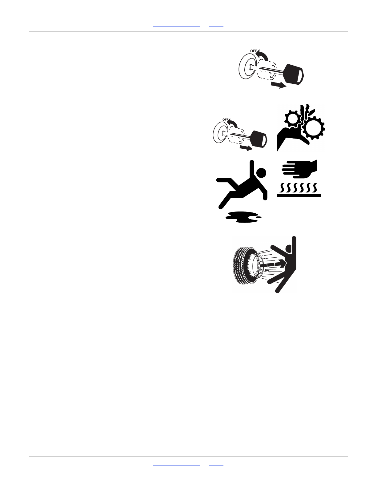
Put tractor in park, turn off engine, and remove key before
performing maintenance.
Make sure all moving parts have stopped and all system
pressure is relieved.
Disconnect battery ground cable (-) before servicing or
adjusting electrical systems or before welding on drill.
Inspect all parts. Make sure parts are in good condition
and installed properly.
Remove buildup of grease, oil or debris.
Remove all tools and unused parts from drill before
operation.
Tire Safety
Tire changing can be dangerous and should be
performed by trained personnel using correct tools and
equipment.
When inflating tires, use a clip-on chuck and extension
hose long enough for you to stand to one side–not in front
of or over tire assembly. Use a safety cage if available.
When removing and installing wheels, use wheel-handling
equipment adequate for weight involved.
Great Plains | 118-245M | 2018-07-18 Table of Contents Index 4
Page 9
1510HDP, 2010HDP and 2510HDP Table of Contents Index Important Safety Information
27130
Safety At All Times
Thoroughly read and understand the instructions in this
manual before operation. Read all instructions noted on
the safety decals.
Be familiar with all drill functions.
Operate machinery from the driver’s seat only.
Do not leave drill unattended with tractor engine running.
Do not dismount a moving tractor. Dismounting a moving
tractor could cause serious injury or death.
Do not stand between the tractor and drill during
hitching.
Keep hands, feet and clothing away from power-driven
parts.
Wear snug-fitting clothing to avoid entanglement with
moving parts.
Watch out for wires, trees, etc., when folding and raising
drill. Make sure all persons are clear of working area.
Safety Reflectors and Decals
Your drill comes equipped with all lights, safety reflectors
and decals in place. They were designed to help you
safely operate your drill.
Read and follow decal directions.
Keep lights in operating condition.
Keep all safety decals clean and legible.
Replace all damaged or missing decals. Order new decals
from your Great Plains dealer. Refer to this section for
proper decal placement.
When ordering new parts or components, also request
corresponding safety decals.
To install new decals:
1. Clean the area on which the decal is to be placed.
2. Peel backing from decal. Press firmly on surface,
being careful not to cause air bubbles under decal.
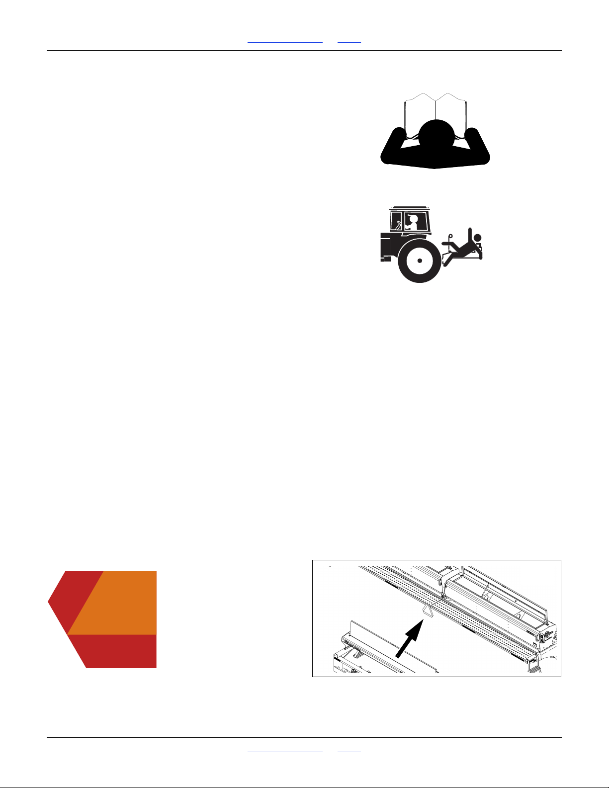
Slow Moving Vehicle Reflector
818-055C
reflector is mounted at center rear edge of walkboard(s);
1 total
Great Plains | 118-245M | 2018-07-18 Table of Contents Index 5
Page 10
1510HDP, 2010HDP and 2510HDP Table of Contents Index Important Safety Information
27130
27130
18270
27130
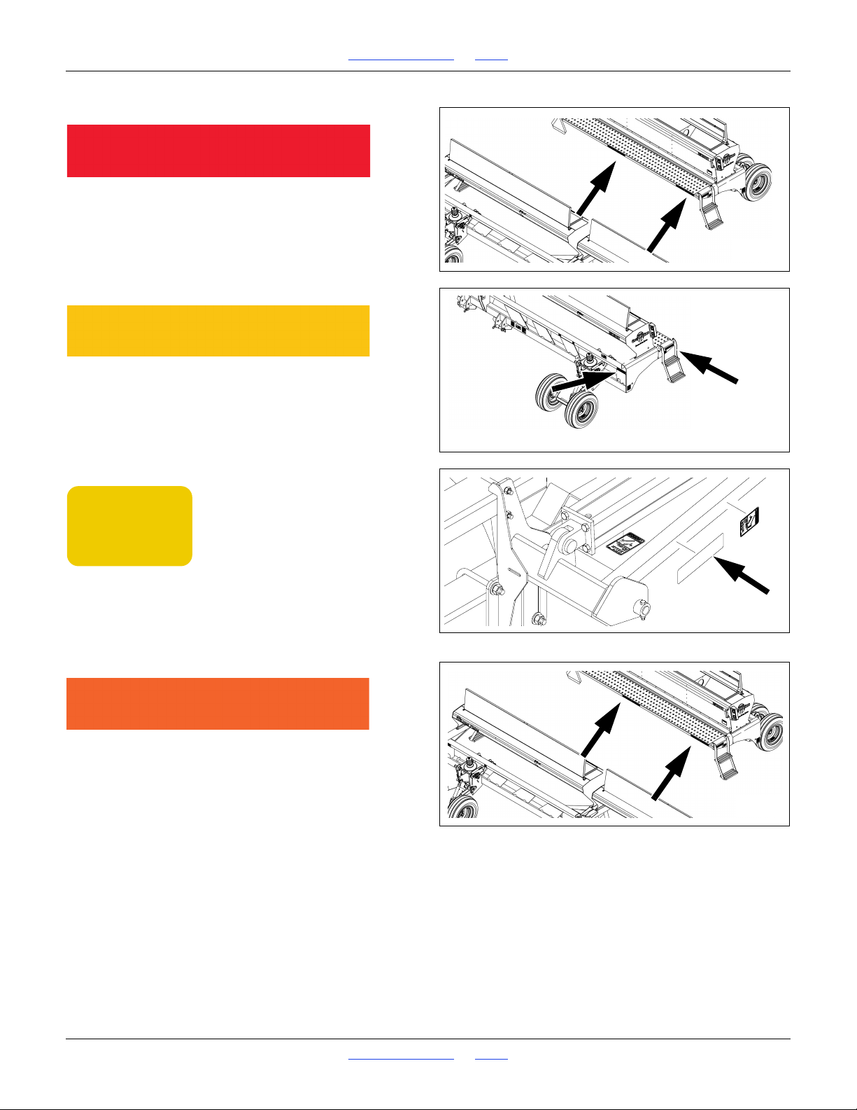
Red Reflectors
838-266C
Rear walkboard face, outside corner (all models),
rear walkboard face, center (2010HDP and 2510HDP);
2 or 4 total
Amber Reflectors (large)
838-265C
On outside end faces of walkboards at ladder top,
front top face of mainframe, each outside corner;
4 total
Amber Reflectors, small (Option)
818-229C
On front face of first section of marker;
1 total per marker
Daytime Reflectors
838-267C
Rear walkboard face, inboard of red reflectors;
2 (on 1510HDP) or
4 (on 2010HDP and 2510HDP) total
Great Plains | 118-245M | 2018-07-18 Table of Contents Index 6
Page 11
1510HDP, 2010HDP and 2510HDP Table of Contents Index Important Safety Information
27130
848-512C
WARNING:
Cancer and Reproductive Harm - www.P65Warnings.ca.gov
27130
27130
WARNING
EXCESSIVE SPEED
HAZARD
To Prevent Serious Injury or Death:
Do NOT exceed 20 mph maximum
transport speed. Loss of vehicle
control and/or machine damage
can result.
818-337C Rev. B
27130
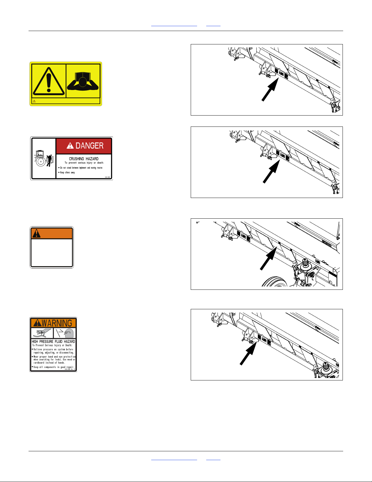
Danger: Read Manual
848-512C
On tongue at hitch;
1 total
Danger: Crushing Hazard
818-590C
On front face of mainframe, right of 3-point hitch;
1 total
Warning: Excessive Speed Hazard
818-337C
On front face, top front of mainframe, above each gauge
wheel assembly;
2 total
Warning: High Pressure Fluid
818-339C
On front face of mainframe, right of 3-point hitch;
1 total
Great Plains | 118-245M | 2018-07-18 Table of Contents Index 7
Page 12
1510HDP, 2010HDP and 2510HDP Table of Contents Index Important Safety Information
18270
27130
WARNING
To avoid serious injury or death:
Watch your step when climbing ladder or
walking on walkboard.
838-102C
27130
27130
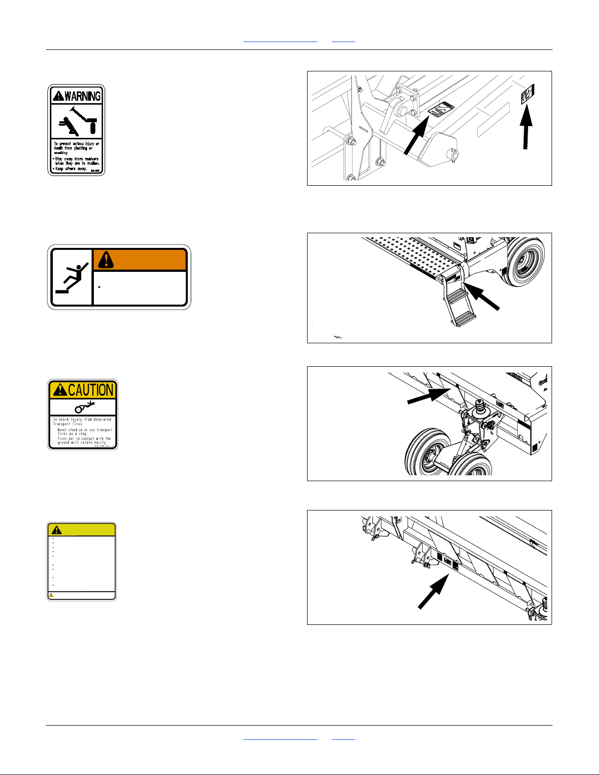
Warning: Marker Pinch Crush (Option)
818-682C
On front and top faces, inner marker section,
2 per marker; 4 total
Warning: Falling Hazard
838-102C
On outside face of mainframe, forward of ladder;
2 total
Caution: Tires Not A Step
818-398C
On front face, top front of mainframe, above each gauge wheel assembly;
2 total
Caution: Read Manual
CAUTION
Read Owner’s Manual before using machine.
Stand clear when folding and unfolding markers.
Stand clear when raising and lowering machine.
Keep all safety shields and devices in place.
Keep hands, feet, and clothing away from
moving chains and sprockets.
Never ride on machine.
Always lower or properly support machine
BEFORE servicing.
Escaping hydraulic fluid can cause serious
injury.
Review safety instructions with all operators
annually.
Cancer and Reproductive Harm - www.P65Warnings.ca.gov
WARNING:
818-587C Rev. B
818-587C
On front face of mainframe, right of 3-point hitch;
1 total
Great Plains | 118-245M | 2018-07-18 Table of Contents Index 8
Page 13
1510HDP, 2010HDP and 2510HDP Table of Contents Index Important Safety Information
24379
27225
26216
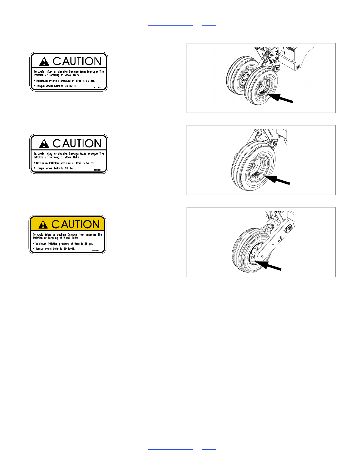
Caution: 32 PSI Tire Pressure
818-751C
On rim of each 9.5L-15-6ply wheel;
2 total
Caution: 52 PSI Tire Pressure
818-752C
On rim of each 11L-15SL-12ply wheel;
2 total
Caution: 36 PSI Tire Pressure
818-855C
On rim of each 11L-15SL-8ply wheel;
4 total
Great Plains | 118-245M | 2018-07-18 Table of Contents Index 9
Page 14
1510HDP, 2010HDP and 2510HDP Table of Contents Index Introduction
Figure 1
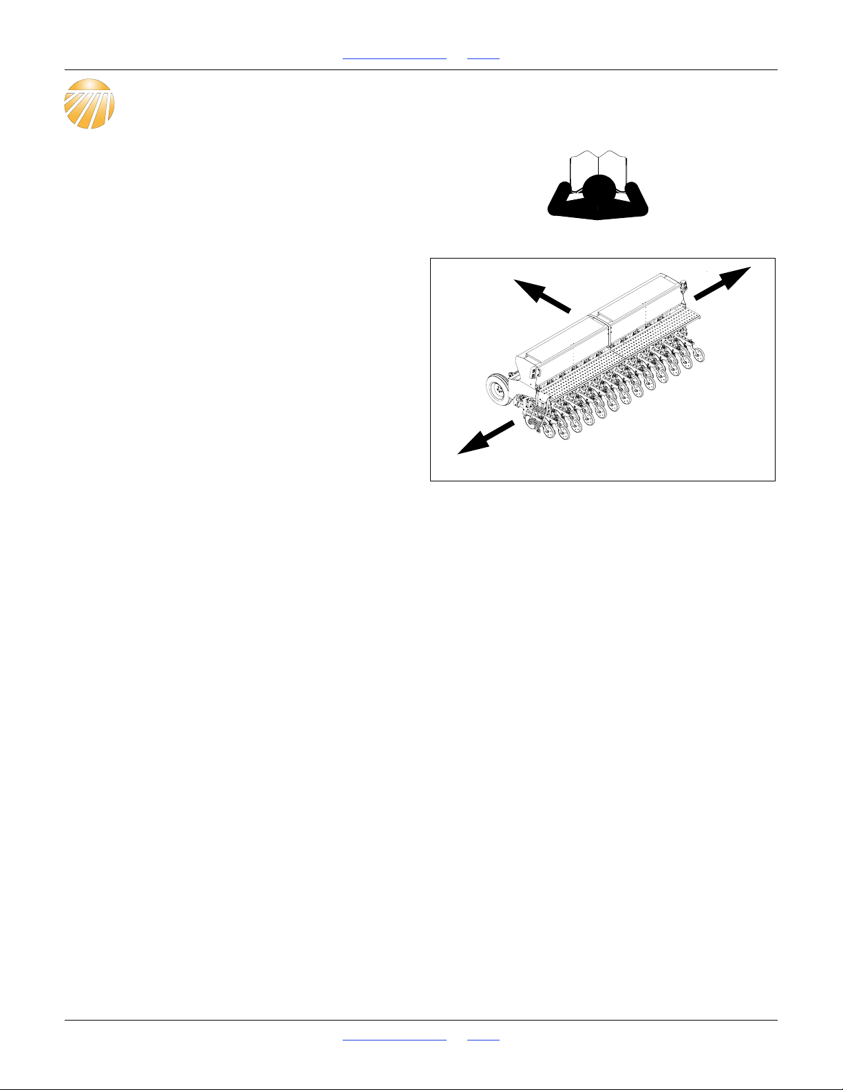
Left/Right Notation
18327
L
R
Introduction
Great Plains welcomes you to its growing family of new
product owners. Your 3-Point Drill has been designed
with care and built by skilled workers using quality
materials. Proper setup, maintenance, and safe
operating practices will help you get years of satisfactory
use from the machine.
Document Family
Great Plains parts:
118-245M Operator Manual (this document)
118-245P 2510HDP Parts Manual
118-928P 2010HDP Parts Manual
119-949P 1510HDP Parts Manual
118-245B Seed Rate Manual
DICKEY-john parts:
11001-1359-200605Seed Monitor Manual
Description of Unit
The products covered by this manual are 15-, 20- and
25-foot 3-point mounted seed drills. They are equipped
with HD10 Series heavy duty row units and precision
seed meters.
Intended Usage
Use this implement to seed production-agriculture crops
in conventional or minimum tillage applications.
Models Covered
1510HDP-12TR15-Foot, 12-Twin Row (6 pair), 30in
1510HDP-131515-Foot, 13-Row, 15in
1510HDP-191015-Foot, 19-Row, 10in
1510HDP-19TRS15-Foot, 19-Row Twin Split
(6 pairs on 30in, plus 7 singles)
1510HDP-247515-Foot, 24-Row, 7.5in
2010HDP-16TR20-Foot, 16-Twin Row (8 pair), 30in
2010HDP-171520-Foot, 17-Row, 15in
2010HDP-251020-Foot, 25-Row, 10in
2010HDP-25TRS20-Foot, 25-Twin Row Split
(8 pairs on 30in, plus 9 singles)
2010HDP-327520-Foot, 32-Row, 7.5in
2510HDP-201525-Foot, 20-Row, 15in
2510HDP-20TR3025-Foot, 20-Twin Row (10 pair), 30in
2510HDP-291025-Foot, 29-Row, 10in
2510HDP-29TRS25-Foot, 29-Twin Row Split
(10 pairs on 30in, plus 9 singles)
2510HDP-407525-Foot, 40-Row, 7.5in
Using This Manual
This manual familiarizes you with safety, assembly, operation, adjustments, troubleshooting, and maintenance.
Read this manual and follow the recommendations to
help ensure safe and efficient operation.
The information in this manual is current at printing.
Some parts may change to assure top performance.
Definitions
The following are used throughout this manual.
Right-hand and left-hand as used in this manual are
determined by facing the direction the machine will travel
while in use unless otherwise stated.
Paragraphs in this format present a crucial point of
information related to the current topic.
Read and follow the directions to:
- remain safe,
- avoid serious damage to equipment and
- ensure desired field results.
Paragraphs in this format provide useful information
related to the current topic.
Great Plains | 118-245M | 2018-07-18 Table of Contents Index 10
Page 15
1510HDP, 2010HDP and 2510HDP Table of Contents Index Introduction
Figure 2
Serial Number Location
16490
Owner Assistance
If you need customer service or repair parts, contact a
Great Plains dealer. They have trained personnel, repair
parts and equipment specially designed for Great Plains
products.
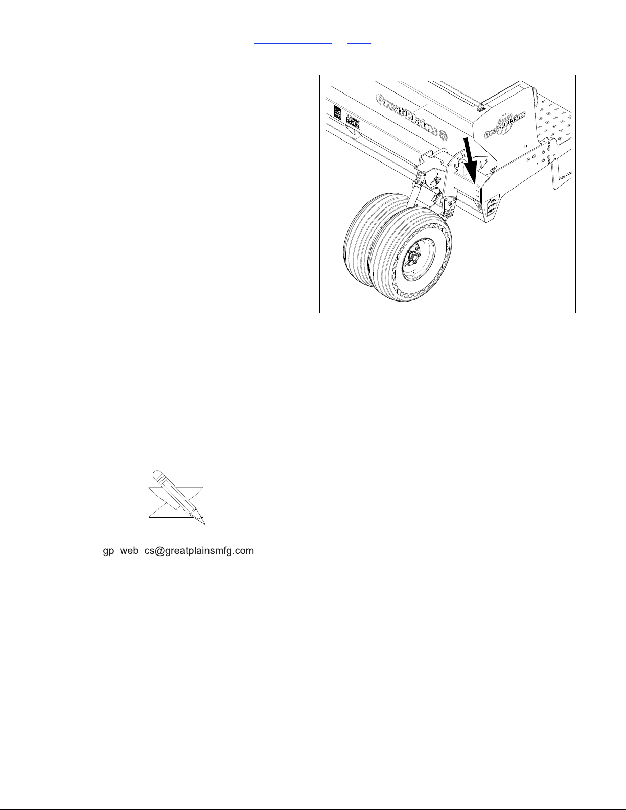
Refer to Figure 2
Your machine’s parts were specially designed and
should only be replaced with Great Plains parts. Always
use the serial and model number when ordering parts
from your Great Plains dealer. The serial-number plate is
located on the left side of the drill frame below the front of
the main seed box.
Record your drill model and serial number here for quick
reference:
Model Number:__________________________
Serial Number: __________________________
Your Great Plains dealer wants you to be satisfied with
your new machine. If you do not understand any part of
this manual or are not satisfied with the service received,
please take the following actions.
1. Discuss the matter with your dealership service
manager. Make sure they are aware of any problems
so they can assist you.
2. If you are still unsatisfied, seek out the owner or
general manager of the dealership.
For further assistance write to:
Product Support
Great Plains Mfg. Inc., Service Department
PO Box 5060
Salina, KS 67402-5060
785-823-3276
Great Plains | 118-245M | 2018-07-18 Table of Contents Index 11
Page 16
1510HDP, 2010HDP and 2510HDP Table of Contents Index Preparation and Setup
Figure 3
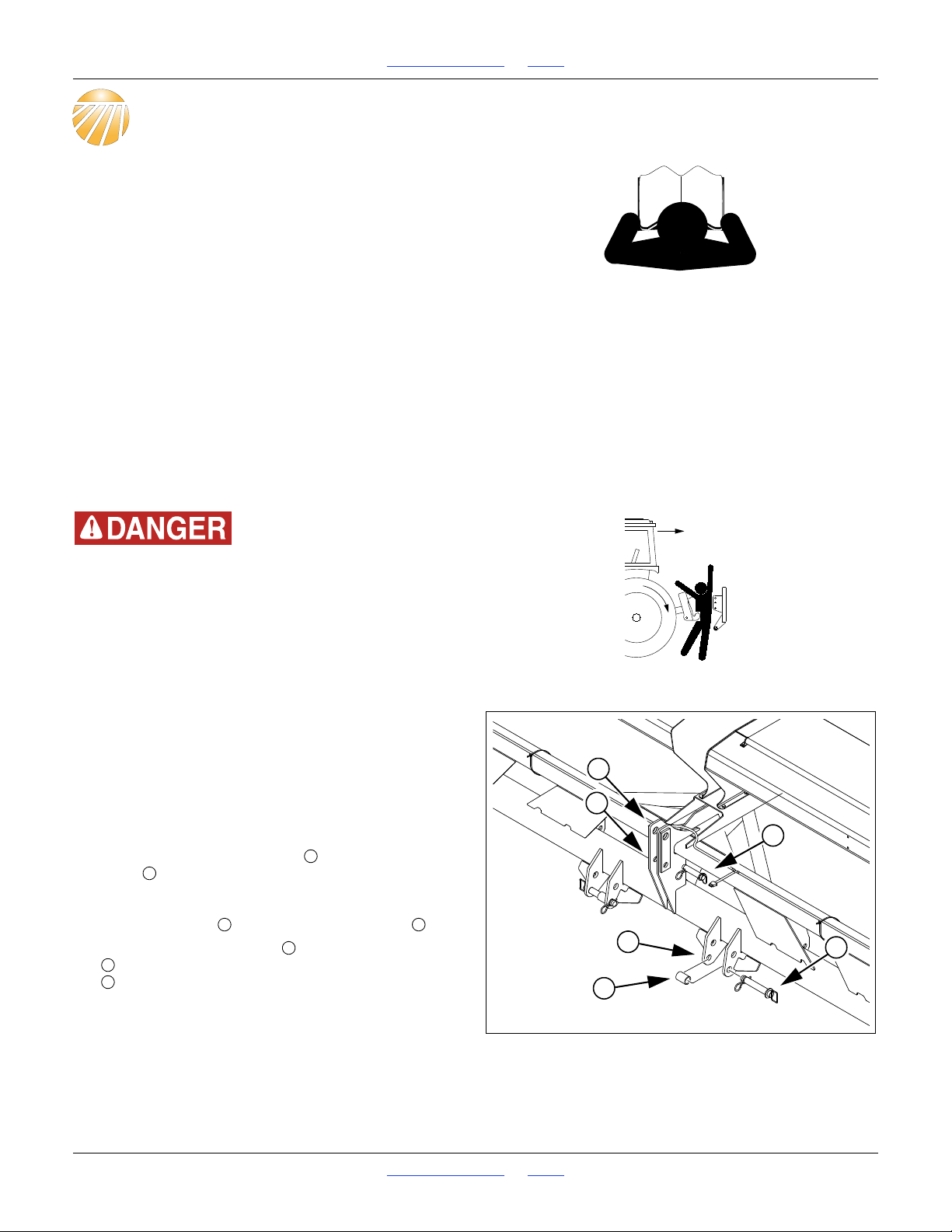
25-foot 3-Point Hitch
27408
1
3
2
5
6
4
1213456
Preparation and Setup
This section helps you prepare your tractor and drill for
use. Before using the drill in the field, you must hitch the
drill to a suitable tractor and also setup the drill.
Pre-Setup Checklist
1. Read and understand “Important Safety
Information” starting on page 1.
2. Check that all working parts are moving freely, bolts
are tight, and cotter pins are spread.
3. Check that all grease fittings are in place and
lubricated. “Lubrication” starting on page 115.
4. Check that all safety decals and reflectors are
correctly located and legible. Replace if damaged.
“Safety Reflectors and Decals” starting on page 5.
5. Inflate tires to pressure recommended and tighten
wheel bolts as specified. “Appendix” on page 132.
Hitching
You may be severely injured or killed by being crushed
between the tractor and drill. Do not stand or place any part of
your body between machines being hitched. Stop tractor and
set parking brake before inserting hitch pins.
20- and 25-foot Hitching
15-foot hitching is on page 13.
These instructions are for a direct 3-point hitch. If using
an optional CPH, PFH or SSH hitch (model 2010HDP
only), consult the hitch manual.
Hitch Setup (20/25ft)
Refer to Figure 3
1. For tractors with category III and III-N hitches,
position the center/upper pin in the bottom center
holes .
For tractors with category IV-N hitches, position the
center/upper pin in the upper center holes
2. Make sure the lower pins are in the bottom holes
of the lower hitch weldments, and that the spacers
are present.
Routine Hitching (20/25ft)
3. Make sure all cables and hoses are clear of the hitch
area.
Great Plains | 118-245M | 2018-07-18 Table of Contents Index 12
Page 17
1510HDP, 2010HDP and 2510HDP Table of Contents Index Preparation and Setup
Figure 4
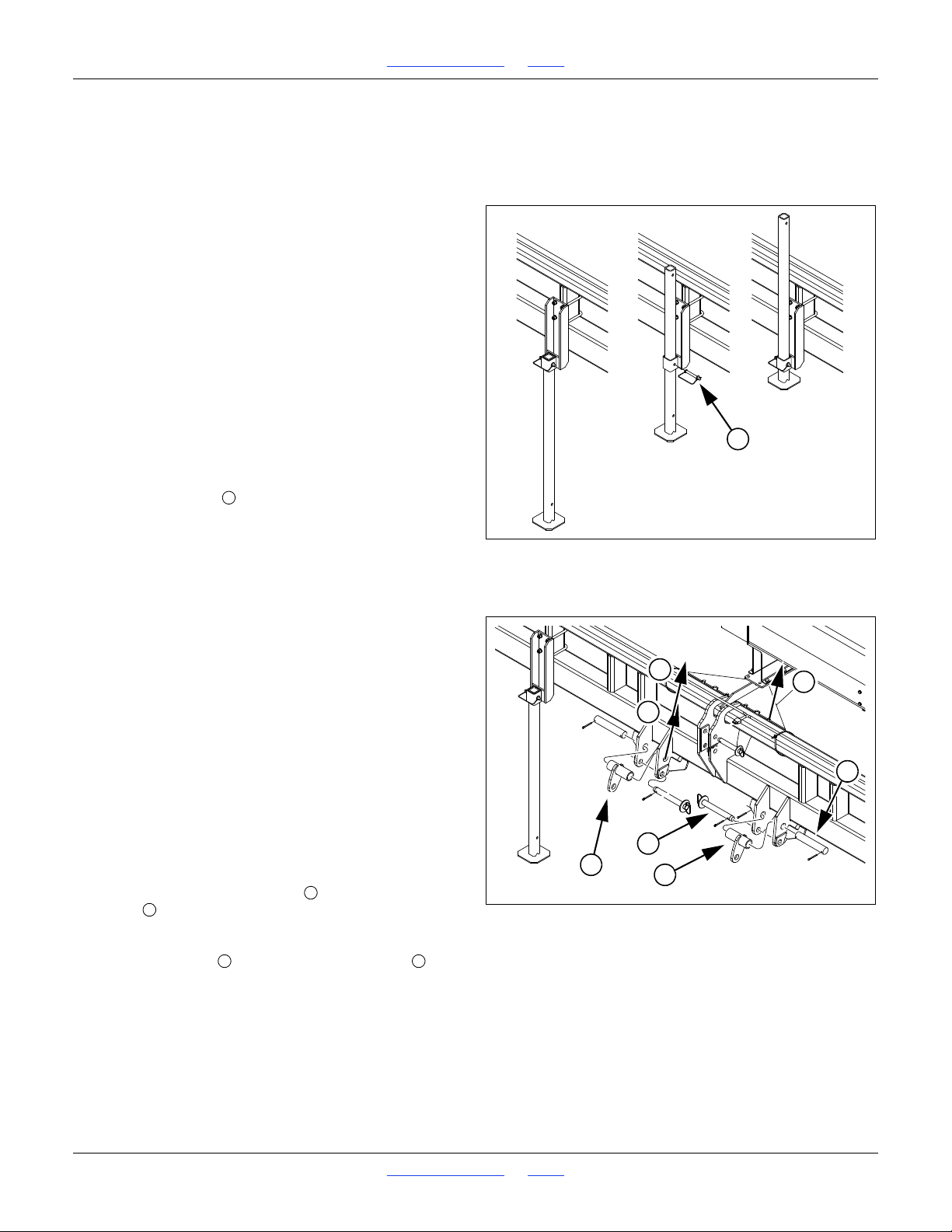
Raise Parking Stand
27410
7
7
Figure 5
15-foot Category II Hitch
27409
5
4
6
6
3
2
1
121
2
4. For a “quick hitch”, align lower arms with lower hitch
points, set spacers and engage lower arms.
For pinned hitch, remove pins and spacers, align
hitch arms and re-pin.
5. Slowly raise drill, watching for cab interference.
6. Adjust top link so that when in field position, top side
of drill mainframe is parallel to the ground.
Do not use 3-point link to adjust opener depth. See
“Planting Depth” on page 34 for a summary of depth
control settings.
7. Set tractor three-point draft control to Float.
8. Skip to “Electrical Connections” on page 14.
Raise Parking Stand (20ft)
Only the 15- and 20-foot drills have these stands (one on
each side). The stand is primarily needed when an
accessory hitch is used.
9. Make sure the drill raising at step 5 above has
removed all weight carried by the stands.
10. Remove the pins .
11. Slide the stand tube up in the sleeve (you may also
invert the tube, with the foot plate on top).
12. Re-insert the pin.
15-foot Hitching
20- and 25-foot hitching is on page 12.
These instructions are for a direct 3-point hitch. If using
an optional CPH, PFH or SSH hitch, consult the hitch
manual.
Hitch Setup (15ft)
Some tractor 3-points may require additional bushings
(not supplied by Great Plains) to adapt the pin diameters:
Upper Link: Qty 1, 1in ID x 1
Lower Link: Qty 2, 1
1
8
Refer to Figure 5 and Figure 6
As supplied from the factory, 1510HDP hitches are set
for category II.
1. For tractors with category III and III-N hitches,
position the center/upper pin in the bottom center
holes .
For tractors with category IV-N hitches, position the
center/upper pin in the upper center holes
1
in ID x 1
in OD
4
7
16
in OD
Great Plains | 118-245M | 2018-07-18 Table of Contents Index 13
Page 18
1510HDP, 2010HDP and 2510HDP Table of Contents Index Preparation and Setup
Figure 6
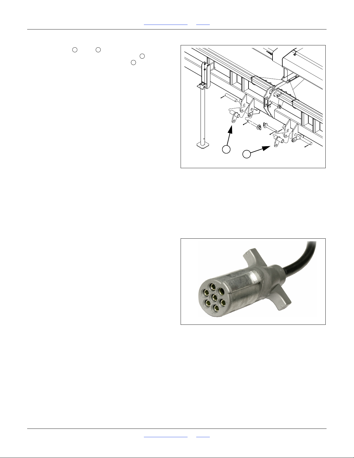
15-foot Category III Hitch
27409
7
7
456
7
Figure 7
Lighting Connector
36051
2. For tractors with category III hitches, remove all
lower pins ( and ) and re-position the pin
supports from their category II positions on the top
pins to their category III positions as shown in
Figure 6.
Routine Hitching (15ft)
Refer to Figure 5 and Figure 6
3. Raise or lower tractor three-point arms as needed
and pin lower arms to drill.
4. Pin upper arm to drill.
For category II, III and III-N tractors, install hitch pin
in the lower hole.
For category IV-N tractors, install hitch pin in the
upper hole.
5. Slowly raise drill. Watch for cab interference.
6. If drill has parking stands, pin them up. See page 13
for details.
7. Adjust top three-point link so that top edge of drill
box is parallel with ground when drilling.
Do not use link to adjust opener depth. For opener
adjustments, refer to “Leveling the Drill” on page 18
and “Adjustments” starting on page 34.
8. Set your tractor three-point-Control control to Float
position.
Electrical Connections
Refer to Figure 7
9. Plug drill electrical lead into tractor seven-pin
connector. If your tractor is not equipped with a
seven-pin connector, contact your dealer for
installation.
10. If the drill is equipped with the optional seed monitor,
mate the connector for the cab console.
See “Seed Monitor Cab Module” on page 22 for
installation.
See “Seed Monitor” on page 121 for ordering
information.
Great Plains | 118-245M | 2018-07-18 Table of Contents Index 14
Page 19

1510HDP, 2010HDP and 2510HDP Table of Contents Index Preparation and Setup
11. If the drill is equipped with the optional hydraulic
meter drive, mate the connector for the cab console.
See “Hydraulic Console Installation” on page 23 for
installation.
See “Hydraulic Meter Drive” on page 123 for ordering
information.
12. If the drill is equipped with one or more speed
sensors (radar and.or magnetic) mounted on the drill
mate the connectors for the cab displays.
See “Speed Sensor Installation” on page 22 for
installation.
See “Speed Sensors” on page 121 for ordering
information.
Hydraulic Hose Hookup (Options)
Only trained personnel should work on system hydraulics!
Escaping fluid under pressure can have sufficient pressure to
penetrate the skin, causing serious injury. Avoid the hazard by
relieving pressure before disconnecting hydraulic lines. Use a
piece of paper or cardboard, NOT BODY PARTS, to check for
leaks. Wear protective gloves and safety glasses or goggles
when working with hydraulic systems. Hydraulic fluid injected
under the skin is an extremely serious matter. If such an
accident occurs, seek urgent medical attention from a
physician familiar with this type of injury.
Great Plains | 118-245M | 2018-07-18 Table of Contents Index 15
Page 20
1510HDP, 2010HDP and 2510HDP Table of Contents Index Preparation and Setup
Figure 8
Color Coded Hose Grips
31733
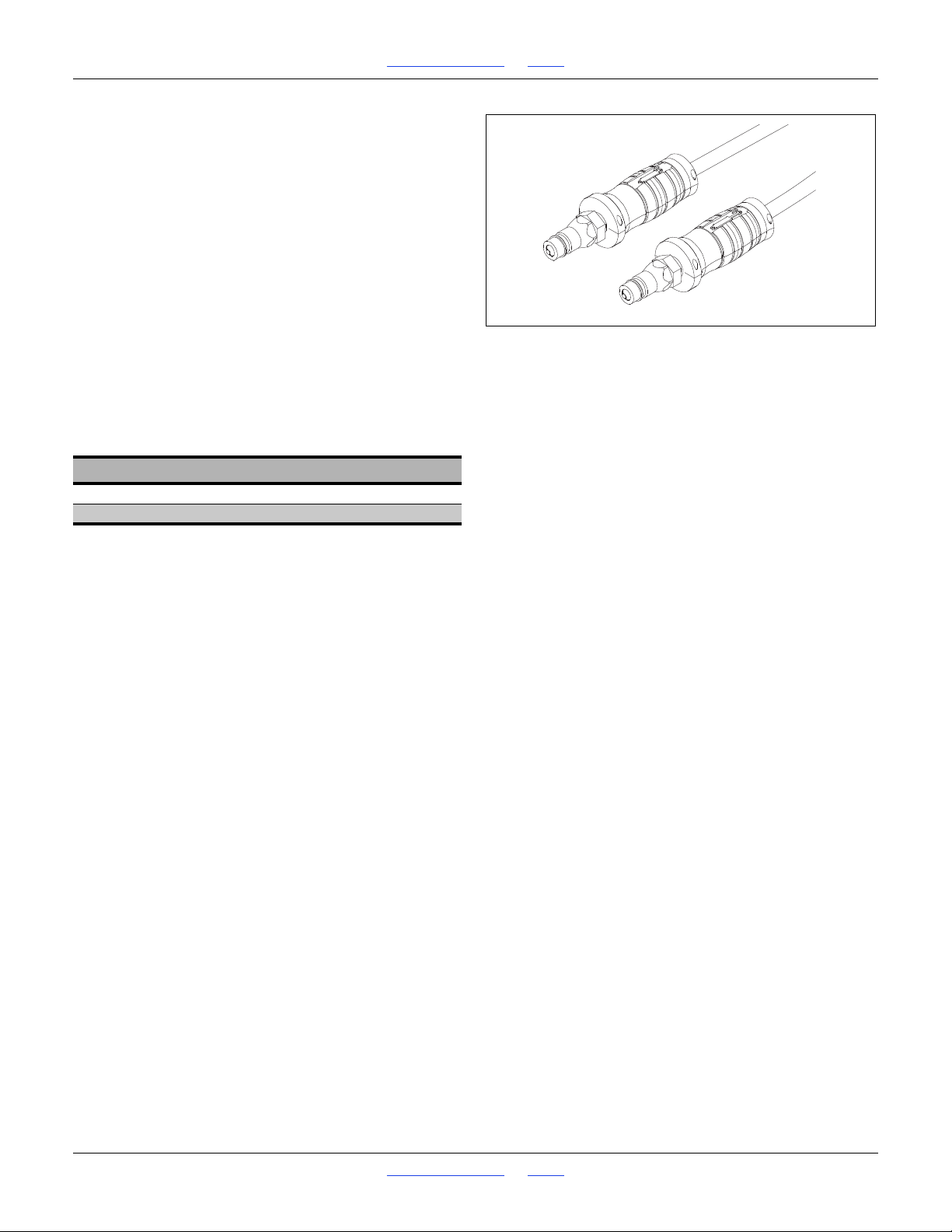
Refer to Figure 8
Great Plains hydraulic hoses have color coded handle
grips to help you hookup hoses to your tractor outlets.
Hoses that go to the same remote valve are marked with
the same color.
To distinguish hoses on the same hydraulic circuit, refer
to the symbol molded into the handle grip. Hoses with an
extended-cylinder symbol feed cylinder base ends.
Hoses with a retracted-cylinder symbol feed cylinder rod
ends.
For hydraulic fan and drive motors, connect the hose
under the retracted cylinder symbol to the pressure side
of the motor. Connect the hose under the extended
cylinder symbol to the return side of the motor.
These instructions presume a direct tractor-drill 3-point
hitching. If an accessory hitch is used, hose routing and
color coding may vary, and there will be one or two
additional circuits (for the hitch lift and tongue).
Color Hydraulic Function
Green Marker Cylinders
Yellow Hydraulic Meter Drive
13. Connect meter drive hoses to tractor remote valve.
14. The optional hydraulic meter drive requires
continuous flow. If the tractor has only one circuit so
rated, or a priority circuit, use that circuit for the drive.
See “Drive Operational Requirements” on page 68
for circuit requirements.
15. Connect marker hoses to tractor remote valve.
16. If this is the first time the drill has been hitched, bleed
the marker hydraulics per the instructions on page
113.
Great Plains | 118-245M | 2018-07-18 Table of Contents Index 16
Page 21
1510HDP, 2010HDP and 2510HDP Table of Contents Index Preparation and Setup
Figure 9
Older Style Hoses with Label
817-348c
17641
Older Style Hoses with Color Ties
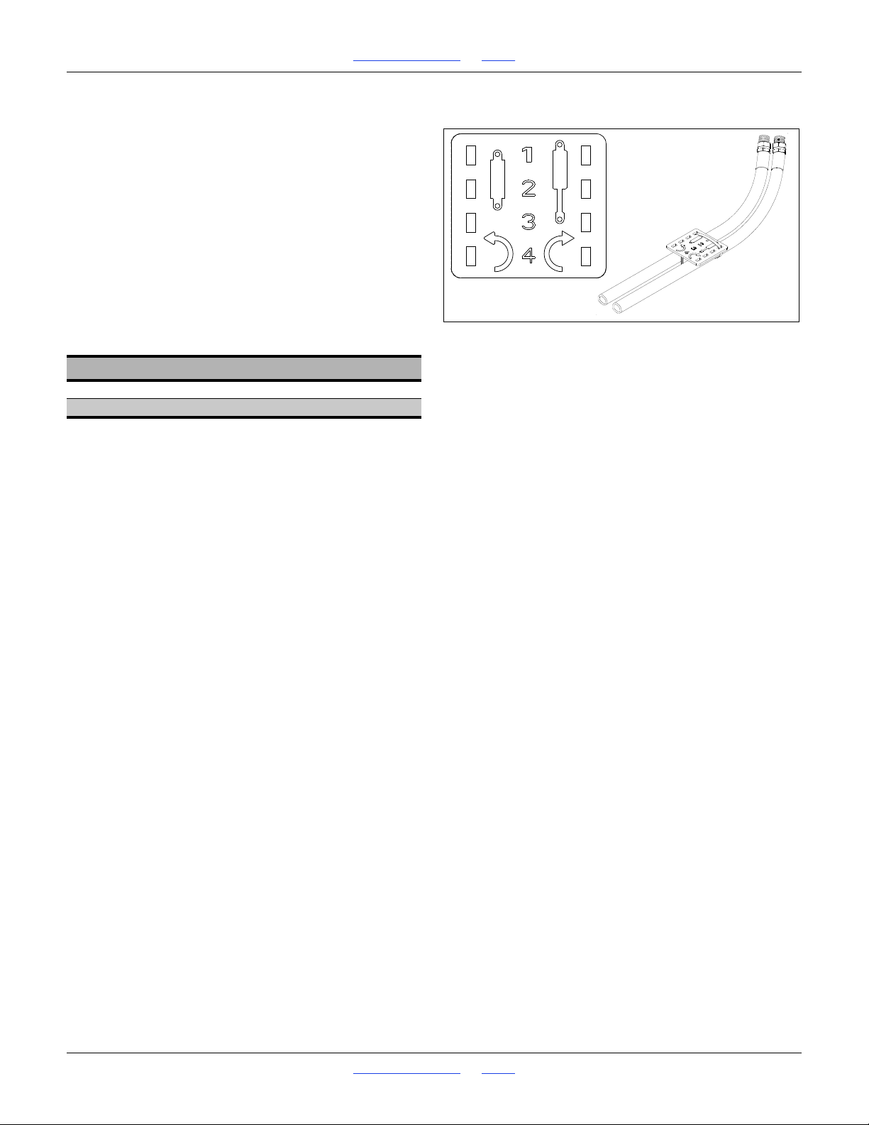
Refer to Figure 8
To distinguish hoses on the same hydraulic circuit, refer
to plastic hose label. The hose under an
extended-cylinder symbol feeds a cylinder base end. The
hose under a retracted-cylinder symbol feeds a cylinder
rod end.
Great Plains hydraulic hoses are color coded to help you
hookup hoses to your tractor outlets.Hoses that go to the
same remote valve are marked with the same color tie.
These instructions presume a direct tractor-drill 3-point
hitching. If an accessory hitch is used, hose routing an
color coding may vary, and there will be one or two
additional circuits (for the hitch lift and tongue).
Color Hydraulic Function
Orange Marker Cylinders
Yellow Hydraulic Meter Drive
Great Plains | 118-245M | 2018-07-18 Table of Contents Index 17
Page 22

1510HDP, 2010HDP and 2510HDP Table of Contents Index Preparation and Setup
Leveling the Drill
For proper operation, and maximum compensation for
varying ground conditions, the opener parallel arms need
to be parallel to slightly up-hill in normal lowered field
operation. This is controlled by two factors:
• the opener tool bar height, which is controlled by
adjustments to the gauge wheels, and;
• front-to-back level, which is controlled by the 3-point
hitch.
The procedure for setting initial drill height and checking
front-to-back level is:
1. Set gauge wheel adjustments to bedded or
non-bedded, via turnbuckle or link and block.
2. Lower drill onto gauge wheels with 3-point.
Set circuit to Float.
3. Adjust 3-point to recommended initial opener tool bar
height.
4. Verify front-to-back level, and adjust with 3-point.
Re-check height.
The adjustment details are different for single gauge
wheel vs. dual gauge wheel or offset single.
See the appropriate page for your drill:
Single-Wheel page 19
Dual- or Offset-Single Wheel page 20
Make the same adjustment on both gauge wheel
assemblies.
Check that drill is still level side-to-side after setup.
Great Plains | 118-245M | 2018-07-18 Table of Contents Index 18
Page 23
1510HDP, 2010HDP and 2510HDP Table of Contents Index Preparation and Setup
Figure 10
Single Wheel Link
26216
26217
5
1
2
3
6
4
1
6
5
12344
Figure 11
Single-Wheel Height
24046
7
756
Figure 12
Single-Wheel Opener Level
24047
8
8
8
Leveling: Single-Wheel
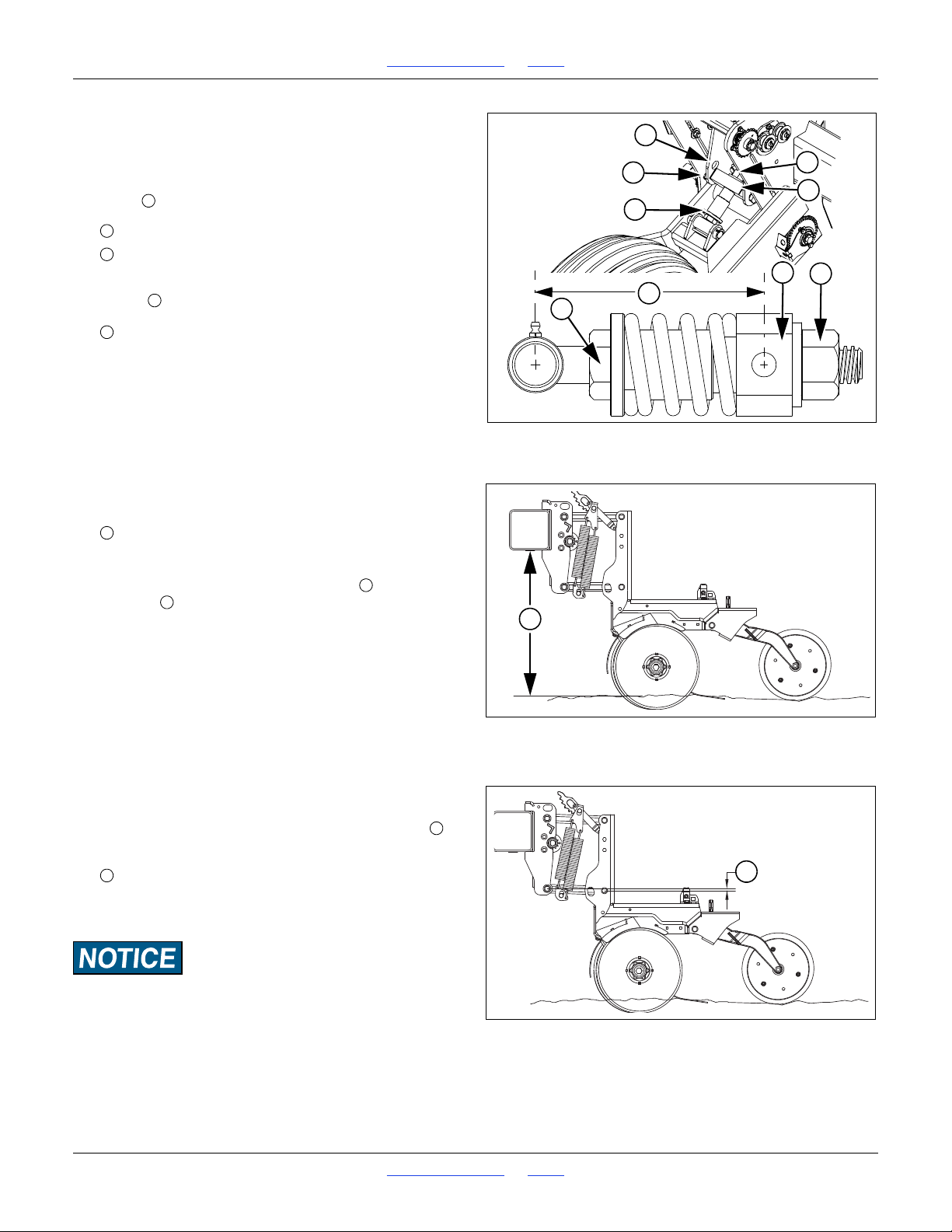
Refer to Figure 10
1. If operations are being changed between
non-bedded and bedded planting, set the spring
block position before checking opener height.
Lower hole Bedded planting
Upper hole Non-Bedded planting
2. Check the link length. The factory setting for link
length , measured at centerlines, is:
Link Length
3. Lower the drill in representative field conditions and
set the 3-point hitch circuit to Float.
Refer to Figure 11
This presumes a planting depth of 1.75in (44mm). If
your depth is different, re-adjust the tool bar height
when adjusting the press-wheel (page 65).
4. Initially adjust drill distance between bottom of
opener tool bar and planting ground:
Tool bar height 26in (66cm)
Refer to Figure 10
5. To adjust link length, loosen jam nut . Turn spring
linkage to shorten or lengthen as necessary.
When adjusting the linkage length, remember:
+ Lengthening linkage raises drill.
- Shortening linkage lowers drill.
Re-tighten jam nut when height is final.
612in (16.5cm)
Refer to Figure 12
6. Level drill with top of three-point link. Adjust so that
row units are inclined slightly uphill, measured at
the ends of the parallel arms:
Arm inclination 1in (2.5cm) maximum
The 1in/2.5cm dimension shown is a general dimension
that varies with planting conditions.
Ensure the opener mount is running higher than the opener
body. This ensures ample reserve for opener upfloat if the
opener strikes a rock or other object.
Great Plains | 118-245M | 2018-07-18 Table of Contents Index 19
Page 24
1510HDP, 2010HDP and 2510HDP Table of Contents Index Preparation and Setup
Figure 13
Offset-Single Wheel Turnbuckle
27221
1
2
3
114
Figure 14
Offset-Single Wheel Height
24050
4
423
Figure 15
Offset-Single Wheel Opener Level
24047
7
7
Leveling: Offset-Single Wheel
The offset-single gauge wheel adjusts for bedding by
changing the turnbuckle length.
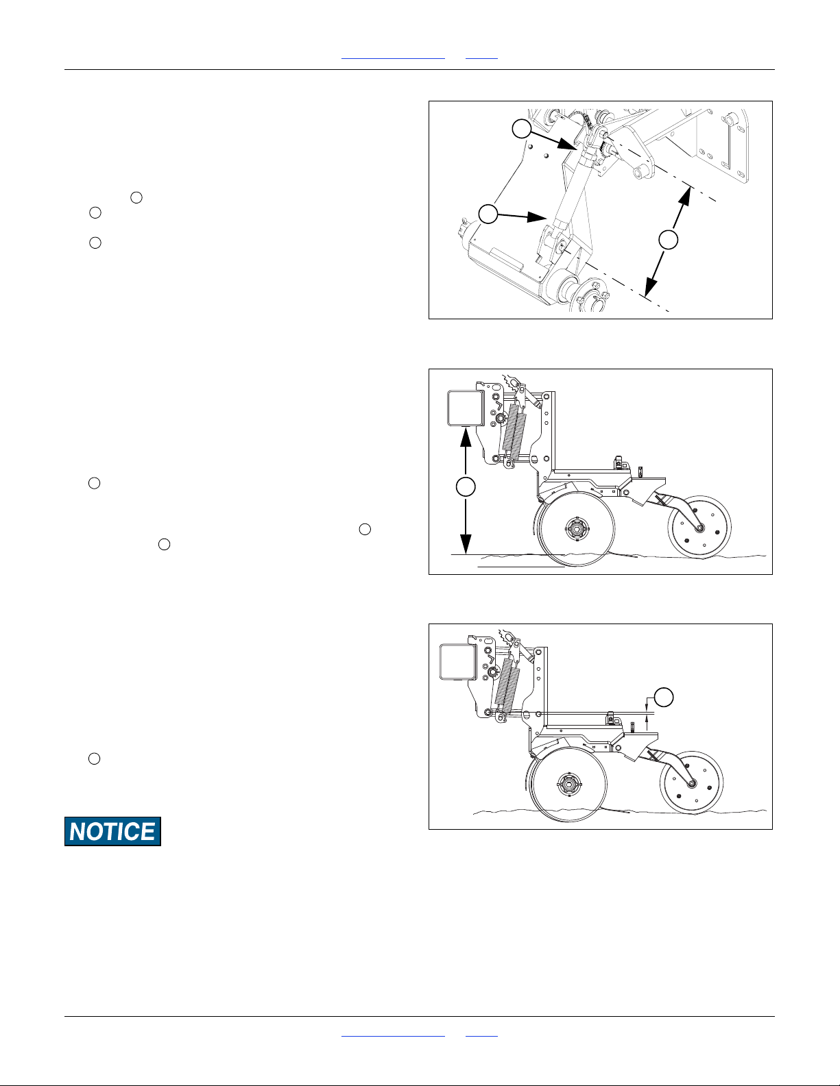
Refer to Figure 13
1. Check the link length. The factory setting for link
length , measured at centerlines, is:
1
17
in (44.5cm)
2
This corresponds to an opener tool bar height of:
26in (66cm)
This is for non-bedded planting.
To adjust the drill for bedded planting:
2. Hitch it to a suitable tractor. Move it to representative
bedded ground, with the wheels between beds.
3. Lower the drill to planting position and set the 3-point
hitch circuit to Float.
Refer to Figure 14
This presumes a planting depth of 1.75in (44mm). If
your depth is different, re-adjust the tool bar height
when adjusting the press-wheels (page 65).
4. Adjust drill distance between bottom of opener tool
bar and planting ground (bed tops):
Tool bar height 26in (66cm)
Refer to Figure 13
5. To adjust turnbuckle length, loosen jam nut . Turn
turnbuckle to shorten or lengthen as necessary.
When adjusting the turnbuckle length, remember:
+ Lengthening turnbuckle raises drill.
- Shortening turnbuckle lowers drill.
Re-tighten jam nut when height is final.
Do not expose more than 3in (7.6cm) of thread at
either end of turnbuckle.
6. Level drill with top three-point link.
Refer to Figure 15
7. Level drill with top of three-point link. Adjust so that
row units are inclined slightly uphill, measured at the
ends of the parallel arms:
Arm inclination 1in (2.5cm) maximum
The 1in/2.5cm dimension shown is a general dimension
that varies with planting conditions.
Ensure the opener mount is running higher than the opener
body. This ensures ample reserve for opener upfloat if the
opener strikes a rock or other object.
Great Plains | 118-245M | 2018-07-18 Table of Contents Index 20
Page 25
1510HDP, 2010HDP and 2510HDP Table of Contents Index Preparation and Setup
Figure 16
Dual-Wheel Turnbuckle
22845
3
1
2
5
6
123
3
Figure 17
Dual-Wheel Height
24050
4
4
5
6
Figure 18
Dual-Wheel Opener Level
24047
7
7
7
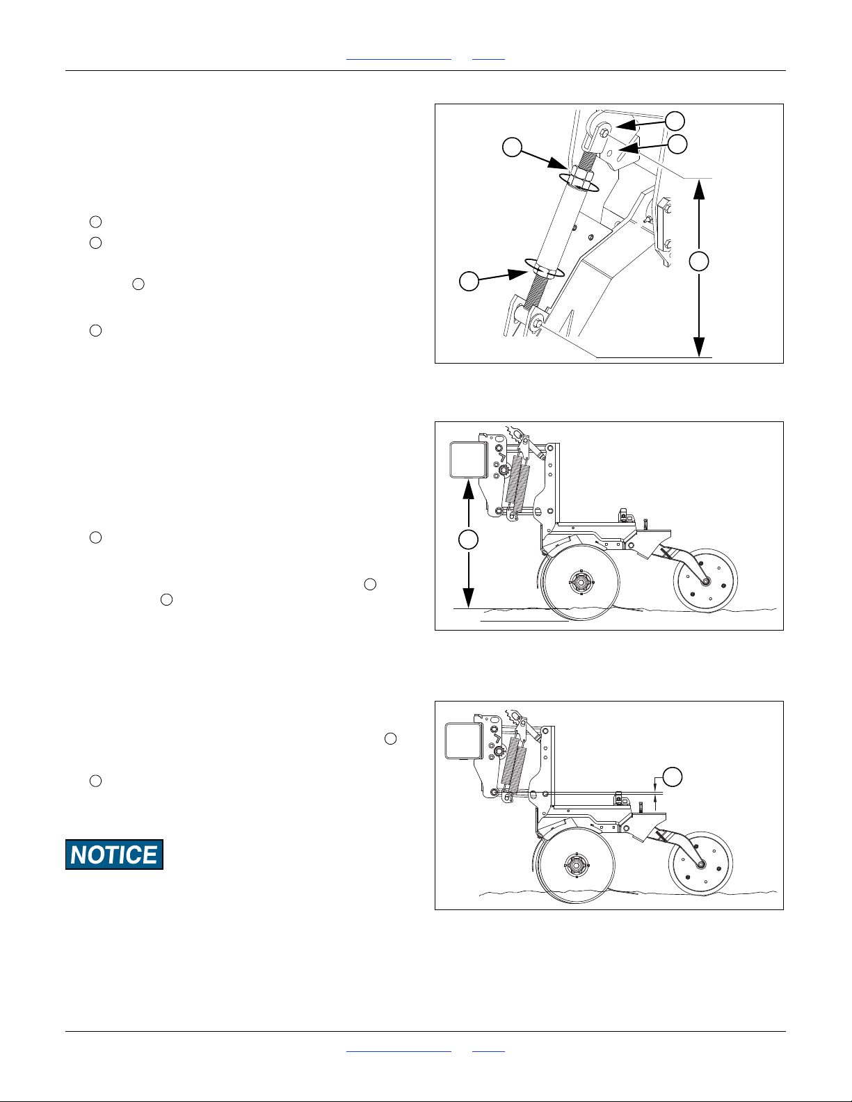
Leveling: Dual-Wheel
Refer to Figure 16
1. If operations are being changed between
non-bedded and bedded planting, set the spring
turnbuckle clevis position before checking length and
opener height.
Lower hole Bedded planting
Upper hole Non-Bedded planting
2. Check the link length. The factory setting for link
length , measured at centerlines, is:
Non-Bedded Bedded
1
17
2in (44.5cm) 2034in (52.7cm)
3. Lower the drill in representative field conditions and
set the 3-point hitch circuit to Float.
Refer to Figure 17
This presumes a planting depth of 1.75in (44mm). If
your depth is different, re-adjust the tool bar height
when adjusting the press-wheel (page 65).
4. Initially adjust drill distance between bottom of
opener tool bar and planting ground:
Tool bar height 26in (66cm)
Refer to Figure 16
5. To adjust turnbuckle length, loosen jam nut . Turn
turnbuckle to shorten or lengthen as necessary.
When adjusting the turnbuckle length, remember:
+ Lengthening turnbuckle raises drill.
- Shortening turnbuckle lowers drill.
Re-tighten jam nut when height is final.
6. Level drill with top three-point link.
Refer to Figure 18
7. Level drill with top of three-point link. Adjust so that
row units are inclined slightly uphill, measured at
the ends of the parallel arms:
Arm inclination 1in (2.5cm) maximum
The 1in/2.5cm dimension shown is a general dimension
that varies with planting conditions.
Ensure the opener mount is running higher than the opener
body. This ensures ample reserve for opener upfloat if the
opener strikes a rock or other object.
Great Plains | 118-245M | 2018-07-18 Table of Contents Index 21
Page 26
1510HDP, 2010HDP and 2510HDP Table of Contents Index Preparation and Setup
Figure 19
Acremeter Installation
27220
4
1
3
6
5
2
1234561
4
Figure 20
Seed Monitor Cab Module
27390
Options Setup
Prior to first use, install any optional equipment that was
not factory- or dealer-installed.
Even if factory- or dealer-installed, some items may need
setup for your specific requirements.
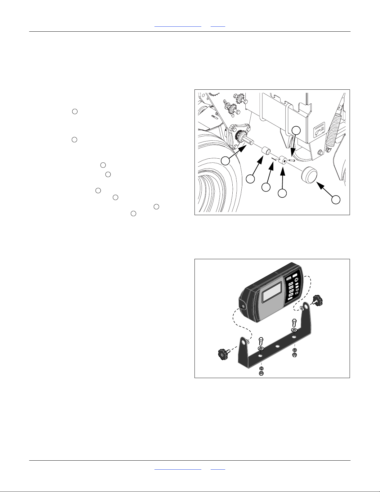
Acremeter Installation
Refer to Figure 19
The acremeter may be supplied from the factory in a
separate carton, to minimize risk of shipping damage.
Check to see if it has already been installed by your
dealer. It is located on the outside end of the upper wheel
arm pivot shaft . It may be installed on either the left or
right gauge wheel.
If not already installed:
1. Slide the spacer tube onto the shaft.
2. Slide the shaft adaptor onto the shaft, aligning its
cross-pin hole with the hole in the shaft.
3. Insert the clevis pin through the adaptor and shaft
and secure with cotter pin .
4. Screw the threaded end of the meter into the
1
-20 tapped hole in the adaptor .
2
Tighten the threaded end only enough to prevent it from
working loose from normal vibration. In use, there is no
torque or tension that might tend to unscrew it.
See “Acremeter Operation” on page 30.
Seed Monitor Cab Module
If your drill has the optional seed monitor, the cab module
may already have been installed by your dealer. If not,
consult the installation instructions included with the
option kit, and mount the module in a convenient
location.
If the cab is particularly noisy, or the operator customarily
wears a noise-cancelling headset, the alarms may not be
audible. Mount the module where the controls and status
indicators are visible during planting operations.
See the separate DICKEY-john manual for initial setup of
the seed monitor.
Speed Sensor Installation
The optional seed monitor requires a speed input in
order to determine seeding rate. The sensor is ordered
separately, and may be a magnetic pickup, or a radar,
mounted on the drill or on the tractor. Consult the
documentation supplied with the sensor.
Great Plains | 118-245M | 2018-07-18 Table of Contents Index 22
Page 27
1510HDP, 2010HDP and 2510HDP Table of Contents Index Preparation and Setup
Figure 21
Hydraulic Drive Cab Module
27392
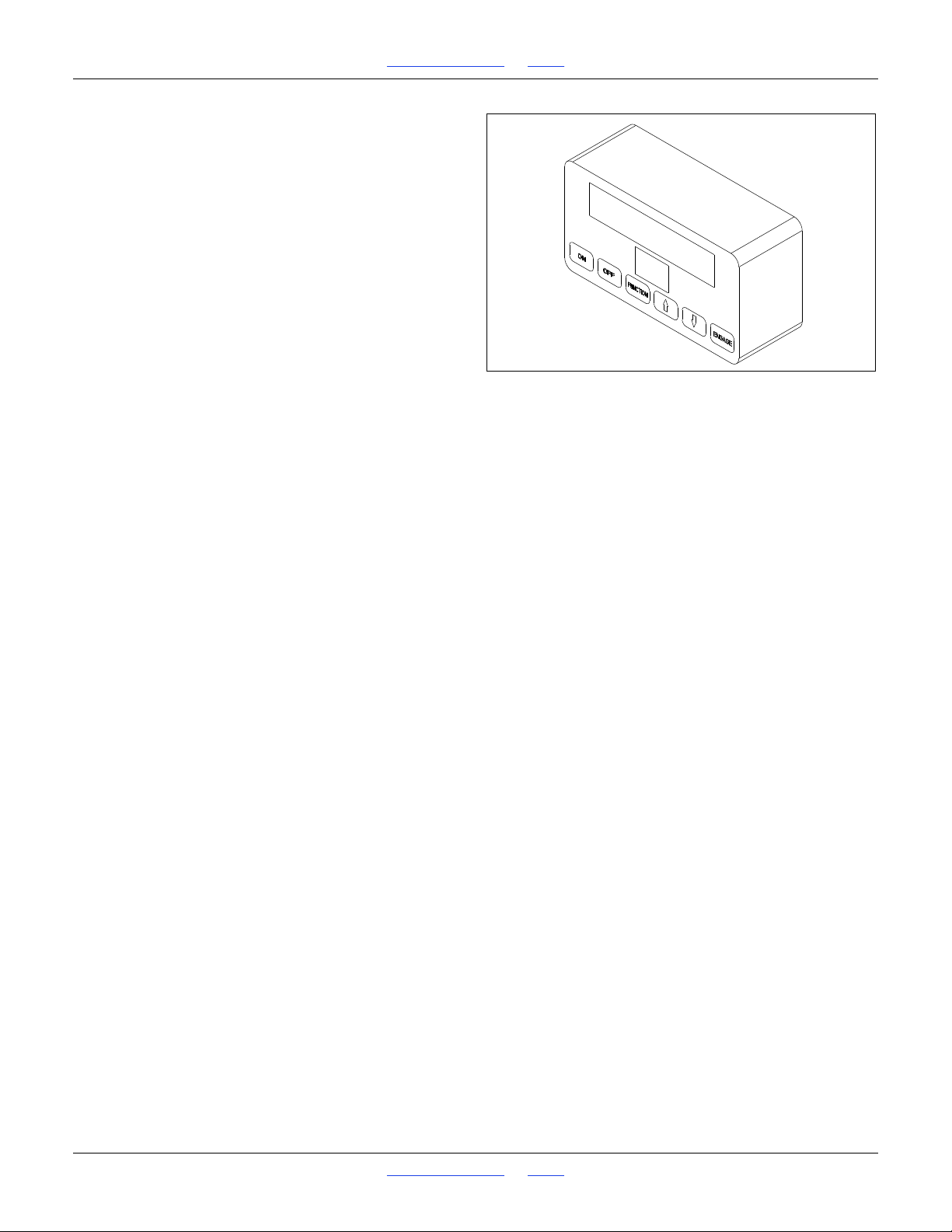
Hydraulic Console Installation
If your drill has the optional hydraulic meter drive, the cab
module may already have been installed by your dealer.
If not, consult the installation instructions included with
the option kit, and mount the module in a convenient
location.
If the cab is particularly noisy, or the operator customarily
wears a noise-cancelling headset, the alarms may not be
audible. Mount the module where the controls and status
indicators are visible during planting operations.
See “Hydraulic Drive Operation” starting on page 68
for initial setup and planting operations.
Great Plains | 118-245M | 2018-07-18 Table of Contents Index 23
Page 28
1510HDP, 2010HDP and 2510HDP Table of Contents Index Preparation and Setup
Figure 22
Marker Chain
15669
1
2
3
12332
1
Marker Setup
This section covers markers installed on the drill. For
markers installed on an accessory hitch, consult the
hitch and/or hitch-marker manual. Marker Extension data
in the Appendix of this manual applies to drill- or
hitch-mounted markers.
If drill-mounted markers were ordered as a separate
accessory, or were not dealer-installed, mount them per
the installation instructions supplied with the markers.
Marker Chain Adjustment
There are two, interrelated adjustments for the marker
chain. Make these adjustments in the following order.
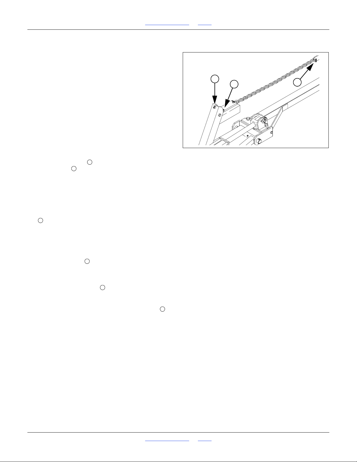
Refer to Figure 22
Marker Lifting Slack
1. Unfold marker.
2. Loosen jam nuts on both sides of channel at
adjuster bolt .
3. Thread bolt in (up) until head is flush with inside jam
nut and both are flush with inside of channel.
4. Slowly fold marker while observing disk. If marker
disk drags across ground more than 12in (30cm)
before lifting, the chain is too long.
5. Shorten chain one or two links by moving clevis bolt
up chain a few links. Check adjustment by
repeating folding process.
6. If chain is too short when marker is unfolded, it will
prevent end of marker from dropping into field
depressions, causing skips in your marker line.
Correct this condition by lengthening chain one or
two links at clevis .
Folding Slack
1. Fold marker.
2. Extend adjustment bolt to take slack out of chain
while marker is folded. Extend bolt until there is no
chain slack.
3. Lock bolt in this position by tightening jam nuts on
either side of upright channel.
Great Plains | 118-245M | 2018-07-18 Table of Contents Index 24
Page 29
1510HDP, 2010HDP and 2510HDP Table of Contents Index Preparation and Setup
E
Figure 23
Marker Extension
E
Figure 24
Marker Extension Adjustment
19204
1
2
122
1
Marker Extension Setup
Check the marker extension, even if already
dealer-installed. The marker’s own installation
instructions may not have covered setting the correct
marker arm length, or may have specified a length not
optimal for your initial planting.
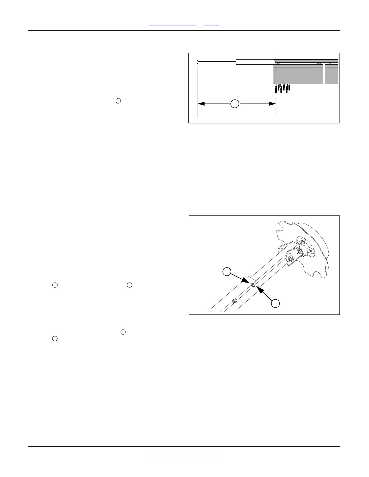
Refer to Figure 23
Set the initial marker extension to the value for your
row spacing from the Appendix starting at page 135.
Measure from the centerline of the end row unit (outer
unit of a twin pair), whether that row is used or not, to the
mark left in the ground when the drill is lowered.
If you modify your row spacing, this can change the
marker extension required. Some custom row spacing
changes result in an asymmetric row spacing about
machine centerline. This usually causes the marker
extension to be different for left and right sides,
depending on the direction of planting for each
successive pass.
Make short practice passes to confirm correct marker
extension.
Marker Extension Adjustment
Refer to Figure 24
To adjust a marker width or disk pivot orientation:
1. Lower drill to field position and extend the marker
side to be adjusted.
2. If disk angle or direction is to be changed, make that
change before adjusting extension.
3. Pull forward to fully settle drill and leave a mark to
check.
4. On telescoping outer marker tubes, loosen both jam
nuts and both
5. Move marker disk tube in or out to get the desired
mark placement. See page 135 for suggested initial
marker extensions, measured from drill centerline.
6. To change throw direction of marker, remove inner
tube completely, and reinsert at desired orientation.
7. Tighten both
nuts .
8. Pull forward to check actual results and fold marker.
Other marker topics in this manual include:
“Marker Operations” on page 32
“Marker Disk Angle” on page 66
“Marker Speed” on page 66
1
in set screws .
2
1
in set screws and then both jam
2
Great Plains | 118-245M | 2018-07-18 Table of Contents Index 25
Page 30
1510HDP, 2010HDP and 2510HDP Table of Contents Index Operating Instructions
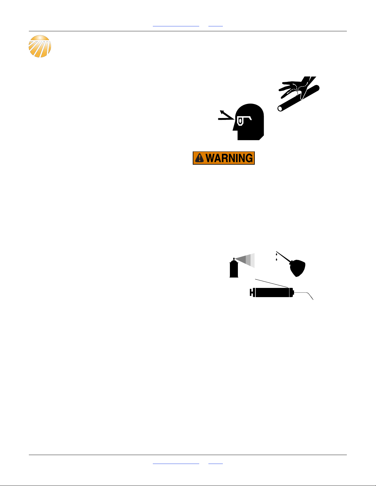
Escaping fluid under pressure can have sufficient pressure to
penetrate the skin. Check all hydraulic lines and fittings before
applying pressure. Fluid escaping from a very small hole can
be almost invisible. Use paper or cardboard, not body parts,
and wear heavy gloves to check for suspected leaks. If injured,
seek medical assistance from a doctor that is familiar with this
type of injury. Hydraulic fluid injected under the skin is an
extremely serious matter. If such an accident occurs, seek
urgent medical attention from a physician familiar with this
type of injury.
Operating Instructions
This section covers general operating procedures.
Experience, machine familiarity and the following
information will lead to efficient operation and good
working habits. Always operate farm machinery with
safety in mind.
Pre-Start Checklist
1. Carefully read “Important Safety Information”
starting on page 1.
2. Lubricate drill as indicated in “Lubrication” starting
on page 115.
3. Check all tires for proper inflation. See “Tire
Inflation Chart” on page 134.
4. Check all bolts, pins and fasteners. Torque as shown
in “Torque Values Chart” on page 135.
5. Check drill for worn or damaged parts. Repair or
replace parts before going to the field.
6. Check any hydraulic hoses, fittings and cylinders for
leaks. Repair or replace before going to the field.
Prepare for Planting
7. Install meters and seed wheels for the intended crop.
See “Meter Adjustments” on page 58.
8. For ground drive, rotate both gauge wheels to see
that the drive and meters are working properly and
free from foreign material.
9. To reduce wear, remove chains for drive systems
that will not be used at present. See page 165 for
chain diagrams.
10. Using the Seed Rate charts, perform the initial setup
of the material rates. See page 35.
11. Turn on the seed monitor (if installed), and configure
it for the materials, row spacing and intended
population. See separate DICKEY-john manual.
12. Turn on the hydraulic drive controller (if installed),
and configure it for the population intended. See
“Hydraulic Drive Operation” starting on page 68.
13. Unless rate checking or calibration will be performed
in the field to be planted, verify or calibrate rates.
See page 38, 40 or 46.
Great Plains | 118-245M | 2018-07-18 Table of Contents Index 26
Page 31
1510HDP, 2010HDP and 2510HDP Table of Contents Index Operating Instructions
WARNING
EXCESSIVE SPEED
HAZARD
To Prevent Serious Injury or Death:
Do NOT exceed 20 mph maximum
transport speed. Loss of vehicle
control and/or machine damage
can result.
818-337C Rev. B
Transporting
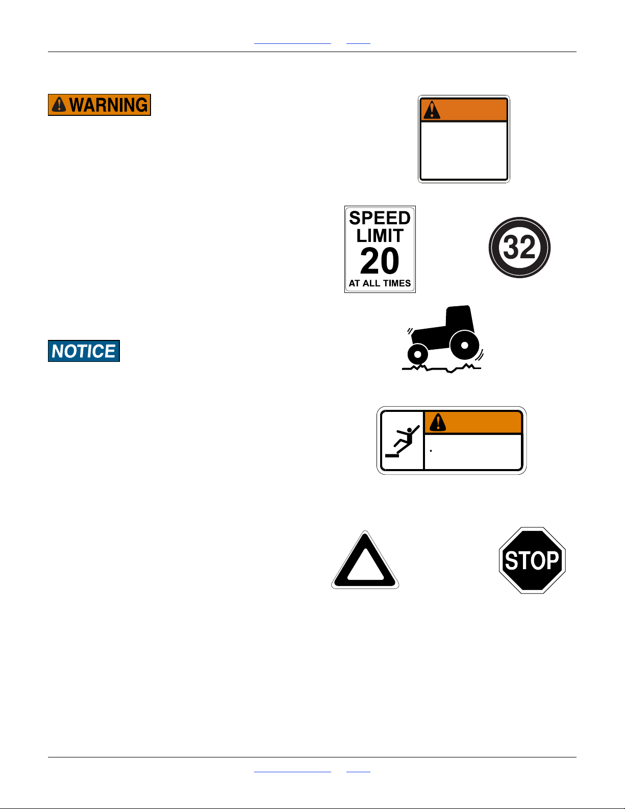
Towing the drill at high speeds or with a vehicle that is not
heavy enough could lead to loss of vehicle control. Loss of
vehicle control could lead to serious road accidents, injury
and death. To reduce the hazard, do not exceed 20 mph (32
kph). Check that your tractor has enough ballast to handle the
weight of the drill. Refer to your tractor operator’s manual for
ballast requirements.
For transporting with drill attached to a hitch, refer to
your hitch operator’s manual.
Before transporting the drill, follow and check these
items:
1. Unload main seed and fertilizer boxes before
transporting if at all possible. See “Materials
Clean-Out” on page 103.
The drill can be transported with a full box of grain,
but the added weight increases stopping distance
and decreases maneuverability.
To maintain steering control, you may need to add ballast to
your tractor front end. Refer to your tractor operator’s manual
for ballast required.
2. Fold up walkboard ladder(s) for maximum clearance.
3. Raise drill for transport.
4. Fold markers.
5. Use lights on drill.
6. Check that needed materials, lubricants, tools,
documents and accessories (such as seed plugs
and baffles) are not left behind.
Road Rules
Comply with all national, regional, state and local safety
laws when traveling on public roads.
Clearance
Remember that the drill is wider than the tractor. Allow
safe clearance.
Transporting with Markers
Always transport markers in the folded position.
WARNING
To avoid serious injury or death:
Watch your step when climbing ladder or
walking on walkboard.
838-102C
Great Plains | 118-245M | 2018-07-18 Table of Contents Index 27
Page 32
1510HDP, 2010HDP and 2510HDP Table of Contents Index Operating Instructions
WARNING
To avoid serious injury or death:
Watch your step when climbing ladder or
walking on walkboard.
838-102C
22878
Loading Materials
If seed is already loaded, and has been present for more
than a day, check that seeds in the sliding seed tubes
and meters has not become damp.
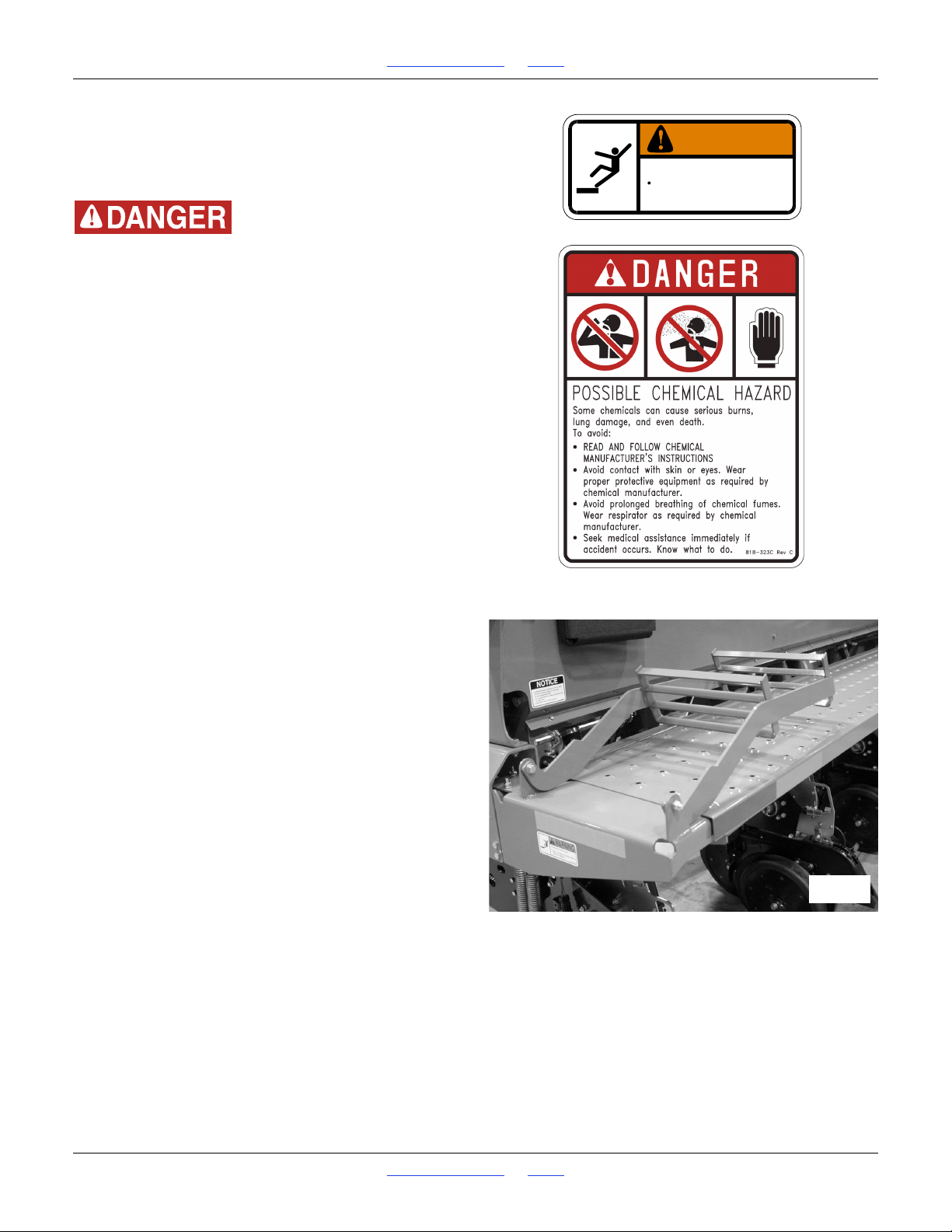
Watch your step when walking on drill ladder and walkboard.
Falling from drill could cause severe injury or death.
Great Plains recommends loading materials after the drill
has been transported to the planting ground.
Seed is heavy. Pre-loading substantially increases
transport hazards:
• Stopping distance increases.
• The center of gravity moves aft. Tractor steering
wheels have less weight on them, reducing steering
effectiveness.
• Even with effective steering, turns are more difficult
to initiate and more difficult to stop, due to the inertia
of the wide load.
To load materials:
1. Load only in dry conditions.
2. If the seed is treated, or if loading fertilizer, wear
protective equipment recommended for the hazards.
3. If seed lubricant is called for in the Seed Rate chart,
have ample quantities on hand.
4. Lower the drill.
5. Fold down the ladders.
6. Open the lids for the boxes to be used.
7. Remove any debris or obstructions from the boxes.
8. If not planting all rows, shut off unused rows. See
page 53.
9. Load seed and/or fertilizer. Mix lubricant as
specified. Load or spread materials evenly across all
partitions. Use a tool or gloved hand.
10. Make a note of the quantity loaded, for later
confirmation of population or application density
desired.
11. Note the acremeter reading. See page 30.
12. Close and secure the box lids.
13. Raise the ladders.
Great Plains | 118-245M | 2018-07-18 Table of Contents Index 28
Page 33
1510HDP, 2010HDP and 2510HDP Table of Contents Index Operating Instructions
29248
25477
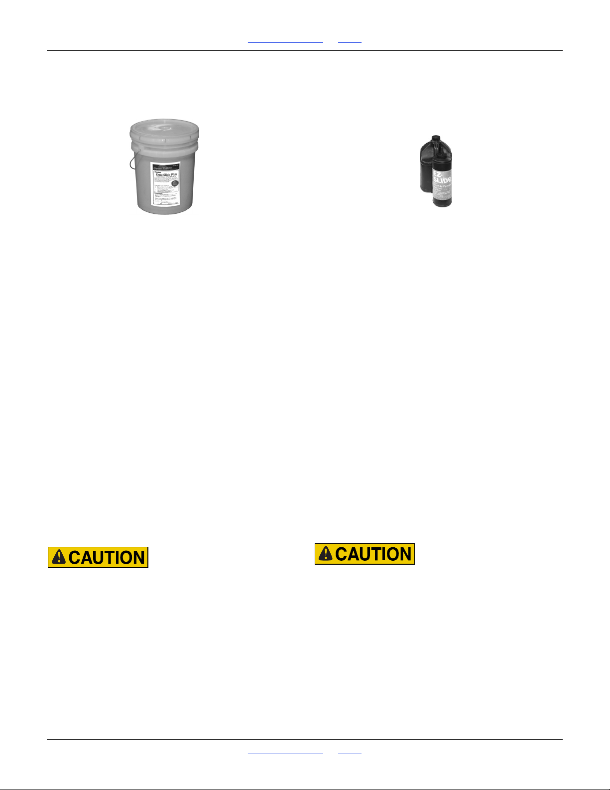
Seed Lubricants
Singulator Plus Meters (all seeds)
Ezee Glide Plus Talc-Graphite Mix
821-069C bucket, 5 gallon (19 liter)
Ezee Glide Plus Lubricant
To maximize performance of Great Plains metering systems, it is imperative to use only “Ezee Glide Plus” lubricant. “Ezee Glide Plus” Talc-Graphite lubricant is
mandatory for all seeds, especially treated or inoculated
seed. Thorough mixing of seed and added lubricant
is required.
Recommended usage:
For clean seeds other than milo and cotton sprinkle
one cup of Ezee Glide Plus Talc per 4 bushels or units
(170 ml per 100 liters) of seed.
For milo and cotton double the application to
one cup (or more) per 2 bu or units (335 ml per 100
liters) of seed.
Adjust this rate as necessary so all seeds become
coated while avoiding an accumulation of lubricant in the
bottom of the hopper.
For seed with excessive treatment, or for humid planting
environments, increase the rate as needed for smooth
meter operation.
Finger Pickup Meters
EZ-Slide Graphite Powder
821-042Cbottle, 1 pound (450 grams)
821-060Cjug, 5 pound (2.3 kg)
For Finger Pick Up Meters Only
Use only approved Graphite Powder available from Great
Plains Mfg. Inc. or Precision Planting to ensure proper
lubrication of finger pickup corn seed meters.
Recommended usage:
For finger pickup meters, add one tablespoon (15 ml) of
graphite for each unit of seed corn (80,000 kernels).
In high humidity conditions, or seeds with heavy seed
treatments, increase the application to two tbsp (30ml).
If delivery of seed from the hopper to the finger meter is
an issue, add “Ezee Glide Plus” talc and graphite blend
at a rate of one cup (237ml) per 4 units of seed. Adjust
until issue is resolved.
Irritation and Chronic Exposure Hazard:
Wear gloves. DO NOT use hands or any part of your body to
mix seed lubricant. Wear a respirator when transferring and
mixing. Avoid breathing lubricant dust. Not an acute hazard.
May cause mechanical eye or skin irritation in high
concentrations. As with all mineral spills, minimize dusting
during clean-up. Prolonged inhalation may cause lung injury.
Irritation and Chronic Exposure Hazard:
Wear gloves. DO NOT use hands or any part of your body to
mix seed lubricant. Wear a respirator when transferring and
mixing. Avoid breathing lubricant dust. Not an acute hazard.
May cause mechanical eye or skin irritation in high
concentrations. As with all mineral spills, minimize dusting
during clean-up. Prolonged inhalation may cause lung injury.
Product can become slippery when wet.
Great Plains | 118-245M | 2018-07-18 Table of Contents Index 29
Page 34
1510HDP, 2010HDP and 2510HDP Table of Contents Index Operating Instructions
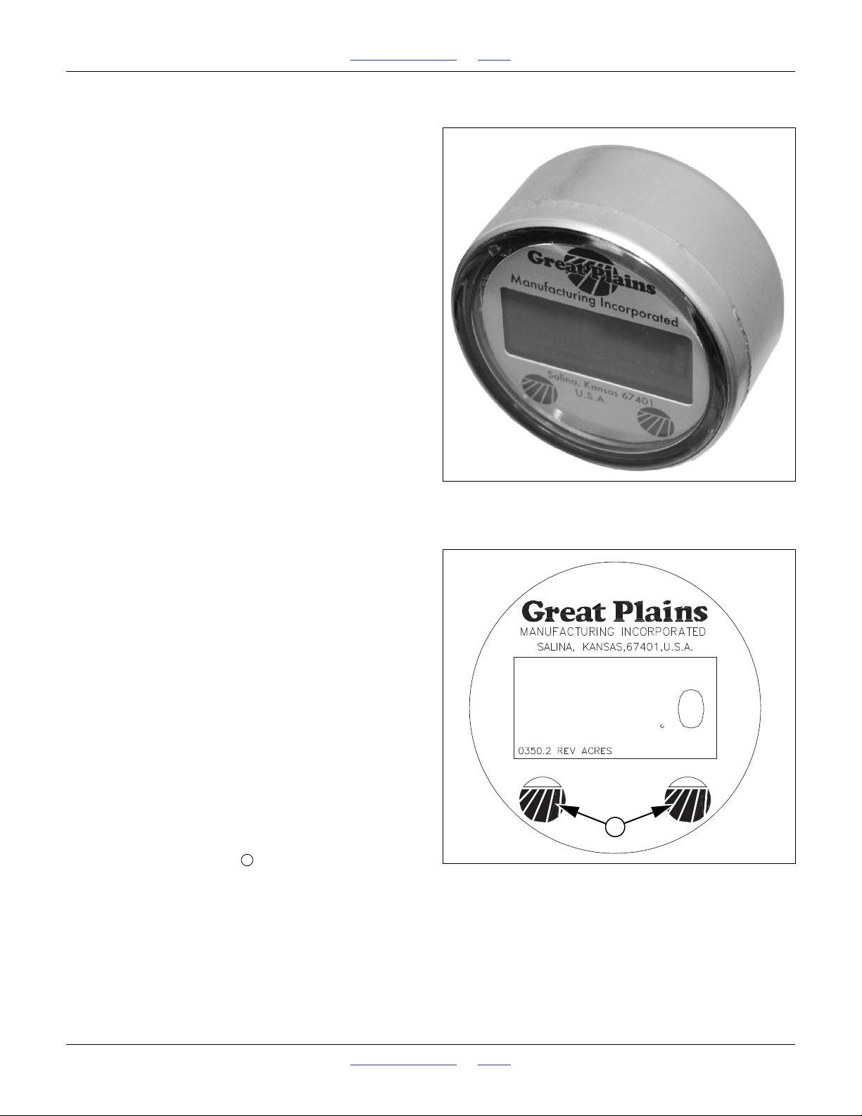
Figure 25
Electronic Acremeter
27378
Figure 26
Meter Display
27380
1
1
Acremeter Operation
The acremeter counts shaft rotations whenever the shaft
is rotating - normally this is only with the drill lowered and
in motion. The meter is programmed to display rotations
as acres or hectares, when using all rows,
factory-specified tires and tire inflations.
Unusual conditions and/or non-standard row
spacings can cause the acremeter tally to vary
somewhat from actual acres planted.
Normal Operating Sequence
The acremeter may count rotations during drill
calibration (and if so, can be useful for calibration).
1. Record the acremeter reading at the start of planting
(and after calibration). The large “12345.6” format
display is the grand total area planted since meter
installation. If the display is blank, see “Dormant
Display” below.
2. Lower drill and plant. Acremeter counts shaft
rotations, calculates acres or hectares, and adds to
the running grand total.
3. During planting (drill lowered and moving forward),
the display blanks (goes dormant), but area tally
continues.
4. When raised for turns, obstructions and transport,
the drill’s ground drive wheel, contact wheel or clutch
disengages the drive shaft, and the meter counts no
additional (non-planting) rotations.
5. Whenever shaft rotation stops, the LCD display
activates after 30 to 60 seconds, and remains visible
for 30 to 45 minutes.
6. At the completion of planting, record the final reading
of the grand total. If the display goes dormant before
you can read it, see “Dormant Display”.
7. Subtract the reading at Step 1 from the reading at
Step 6 for the total planted in the present session.
Dormant Display
Refer to Figure 26
To conserve power, the LCD display blanks itself most of
the time.
If you need to read the display after if has “timed out” and
gone dormant, gently tap or wave a magnet at either of
the Great Plains logo spots on the lower region of the
display. Be careful not to scratch the window.
Great Plains | 118-245M | 2018-07-18 Table of Contents Index 30
Page 35

1510HDP, 2010HDP and 2510HDP Table of Contents Index Operating Instructions
Field Operation
You may be severely injured or killed by being crushed
between the tractor and drill. Do not stand or place any part of
your body between drill and moving tractor. Stop tractor
engine and set park brake before installing pins.
1. Hitch drill to a suitable tractor or hitch. See
“Hitching” on page 12, or your hitch operator’s
manual.
2. Set and calibrate seeding rate as explained at
“Material Rate Adjustments” starting on page 35.
3. Remove chains for material boxes not used. See
page 167.
4. Setup row units for desired down-force and planting
depth. See “Unit-Mounted Coulter Adjustments”
on page 49.
5. Enable or disable seed firmers as desired.
6. If hydraulic drive is installed, Engage the controller
(see page 77).
7. Pull forward, lower drill, set 3-point circuit to Float,
and begin seeding.
8. Always lift drill out of the ground when turning at row
ends and for any short-radius turns. Seeding stops
automatically as drill is raised in the field.
9. If installed, check seed monitor and hydraulic drive
controller for alerts and status.
10. Stop periodically and check that:
• the seed furrows are being covered and closed
(see page 51 for evaluation),
• the acremeter is advancing at the expected rate
(see page 30),
• materials levels are declining evenly across all
rows, at the expected rates, and;
• marker operation - pass-to-pass row alignments
are consistently one row space apart.
Great Plains | 118-245M | 2018-07-18 Table of Contents Index 31
Page 36
1510HDP, 2010HDP and 2510HDP Table of Contents Index Operating Instructions
19196
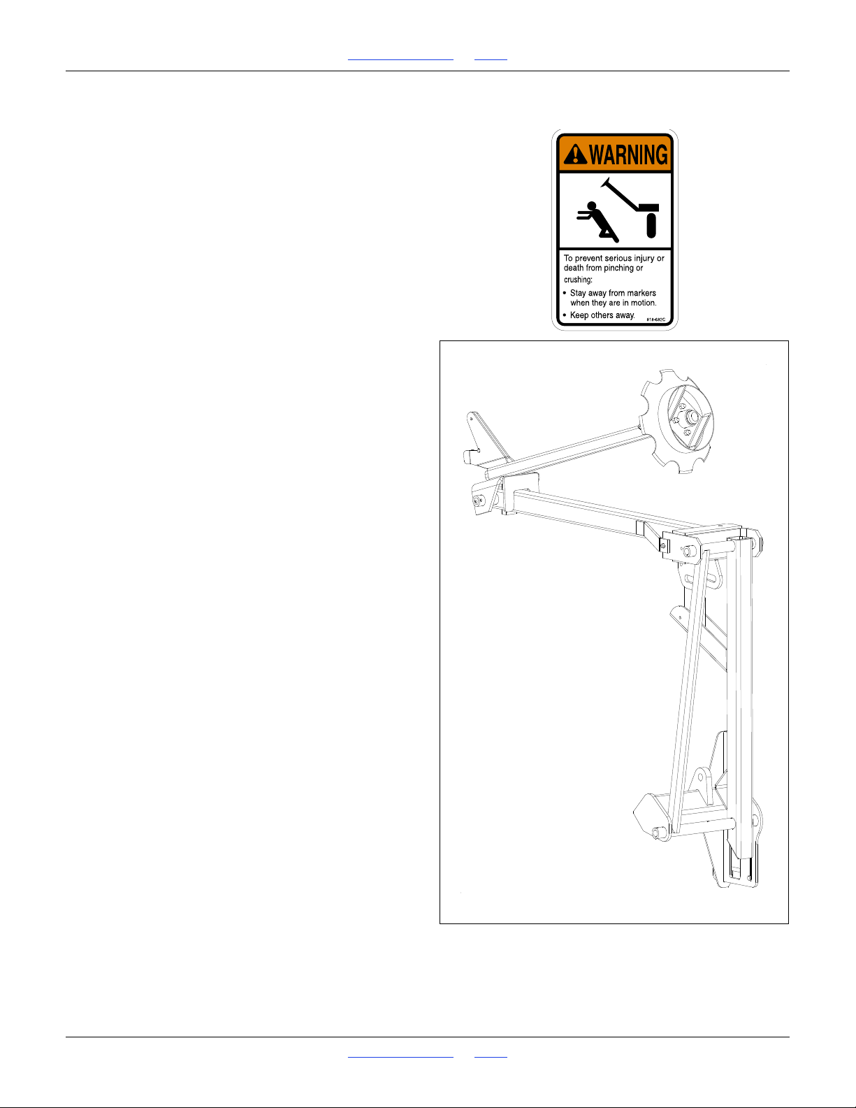
Marker Operations
Optional marker attachments are available from your
Great Plains dealer. Before operating markers, make
sure hydraulics are properly bled as described under
“Bleeding Marker Hydraulics” on page 113.
Set hydraulic circuit lever to neutral when folding or
unfolding is complete. When extended, Great Plains
markers are self-floating over uneven ground. When
folded, neutral locks the marker in the transport cradle.
Independent Markers
Supply oil to the cylinder base end of the marker you
wish to extend. When fully extended, set the circuit lever
to neutral.
Reverse the circuit to fold the marker. When fully resting
in the transport cradle, set the circuit lever to neutral.
Dual Auto-Sequenced Markers
Dual markers on twin dedicated circuits operate the
same as single markers, above.
Dual markers equipped with a sequence valve share the
same hydraulic circuit.
Starting with both markers folded, activate (normally
Extend) the circuit, then set the control to neutral. The
folding sequence is:
• Activate lever - One side unfolds. The other stays
folded.
• Reverse lever - Unfolded side retracts. The other
stays folded.
• Activate lever again - Side that remained folded
previously now unfolds. Original side remains folded.
• Reverse lever - Unfolded side retracts. Original side
remains folded.
• Sequence repeats.
You can adjust dual marker folding speed. See “Marker
Speed” on page 66, and adjust folding speed to a safe
rate. Folding markers at high speed can damage
markers.
Both Sides Extended (Sequenced)
1. Activate lever to extend one side.
2. Reverse lever as if to retract, and quickly reverse
again.
3. Extend the other side.
Great Plains | 118-245M | 2018-07-18 Table of Contents Index 32
Page 37

1510HDP, 2010HDP and 2510HDP Table of Contents Index Operating Instructions
Parking
For information on long-term storage, refer to “Storage”,
next topic.
1. Empty Main Seed and Fertilizer box before
unhitching drill to prevent drill from falling backward.
See “Materials Clean-Out” on page 103.
For parking with drill attached to an accessory hitch,
refer to your hitch operator’s manual.
2. Unload Small Seeds box:
See “Small Seeds Box Clean-Out” on page 103.
Thoroughly clean seed and seed-treatment residue
from boxes and seed meters.
3. Park drill on a level, solid surface.
4. If drill is equipped with parking stands, install them.
See page 13.
5. Lower three-point hitch until drill is on the ground.
6. Disconnect electrical harnesses.
7. Set hydraulic circuits to float and disconnect any
hydraulic connections to the drill.
8. If not using Quick Hitch, extend or retract the top link
of the tractor until top three-point pin is free. Remove
pin.
9. If not using Quick Hitch, remove pins from lower
links.
Storage
1. Store the drill where children do not play. If possible,
store the drill inside for longer life.
2. Perform the Parking checklist, above.
3. Clean out singulating seed meters. Remove them
from drill and store them in sealed containers.
4. Plug or cap delivery tubes to prevent pest entry and
nesting.
5. Remove any dirt and debris that can hold moisture
and cause corrosion.
6. Lubricate and adjust all roller chains.
7. Lubricate areas noted at “Lubrication” starting on
page 115.
8. Inspect drill for worn or damaged parts. Make repairs
and service during the off season.
9. Use spray paint to cover scratches, chips and worn
areas on the drill to protect the metal.
10. Cover with a tarp if stored outside.
Great Plains | 118-245M | 2018-07-18 Table of Contents Index 33
Page 38
1510HDP, 2010HDP and 2510HDP Table of Contents Index Adjustments
Adjustments
To get full performance from your drill, you need an
understanding of all component operations, and many
provide adjustments for optimal field results.
Adjustment Page The Adjustment Affects
Leveling the Drill 18 Consistent control of seeding depth
Marker Adjustments
Marker Extension Setup 25 Pass alignments with no overlap or excessive gap
Marker Disk Angle 66 Visibility of mark for next pass
Marker Speed 66 Efficient marker operation at turns
Material Rate Adjustments 35
Main Box Seed Rate 36 Seed population
Hydraulic Drive Rate 68 Control of seed rate for entire drill
Range Sprockets 37 Coarse control of seed rate at a main box
Transmission Sprockets 38 Fine control of seed rate at a main box
Checking Main Box Seed Rate 38 Precise control of main box seed rate
Small Seeds Attachment Rate 42 Small seed population
Small Seeds Rate Calibration 42 Tuning small seed rate for your specific seed
Fertilizer Rate 45 Material application rate
Fertilizer Density Correction 46 Quicker closure on a rate calibration
Fertilizer Rate Calibration 46 Tuning application rate for your specific material
Seed Monitor Adjustments - See separate DICKEY-john manual
Row Unit Adjustments 48
Unit-Mounted Coulter Adjustments 49 Depth of groove ahead of opener furrow
Row Unit Down-Force 51 Consistent seeding depth in tire tracks
Disk Blade Adjustments 57 Consistent seeding depth
Row Unit Shutoff 53 Alternate row spacings and calibration
Changing Meters 59 Required meter for seed type
Changing Precision Seed Wheels 60 Alternate seeds and available rates within a single seed
Finger Meter Brush Adjustment 62 Consistent metering
Sprocket Indexing (Stagger) 63 Optimal seed-to-seed spacing in twin-row
Seed Firmer Adjustments 64 Reliable seed placement at furrow bottom
Opener Depth (Press Wheel Height) 65 Seeding depth
Even if your planting conditions and rates rarely change,
some of these adjustment items need periodic attention
due to normal wear.
Planting Depth
Setting nominal planting depth, and achieving it
consistently, is affected by multiple adjustable drill
functions, from greatest to least effect they are:
• Leveling the Drill (page 18)
• Opener Depth (Press Wheel Height) (page 65)
• Row Unit Down-Force (page 51),
• Optional Accessory Hitch settings and Coulter
Setup,
• Unit-Mounted Coulter Depth Adjustment (page 49),
• Disk Blade Adjustments (as row unit blades wear,
page 57).
Great Plains | 118-245M | 2018-07-18 Table of Contents Index 34
Page 39
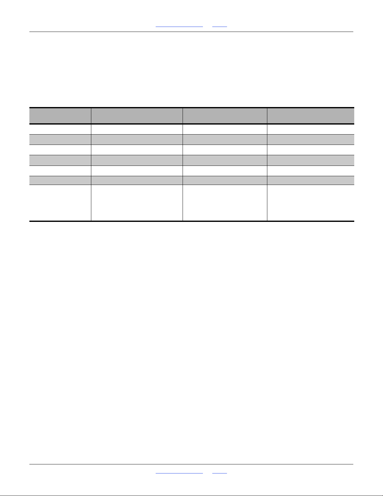
1510HDP, 2010HDP and 2510HDP Table of Contents Index Adjustments
Material Rate Adjustments
Using ground drive, material rates for each of the boxes
are set independently.
Using hydraulic drive, rates for both main seed boxes are
set simultaneously from the cab control.
The following table summarizes the rate adjustments
available (including complete shutoff).
Adjustment Main Seed Page
Meter Type
Seed Wheel
c
Range
Transmission
Cab Control
c
e
Row Coarse Rate
Row Coarse RatebSee
Box Coarse Rate 37
Box Fine Rate 38
Drill Seed Rate 68
a
59 N/A - N/A -
60 N/A - N/A -
Small Seeds
Attachment
d
N/A
d
N/A
f
N/A
Page Fertilizer Page
-
-
-
N/A
N/A
N/A
d
d
f
Rate Adjuster Scale N/A - Controls Box Rate 42 Controls Box Rate 45
Sliding Cap at Meter
Disengage Meter
Row Shutoff
Seed Tube Cork
Seed Box Baffles
Lock Up Row Unit
a. 10HDP row units support either Great Plains Singulator Plus precision meters, or finger pickup meters, which differ in the seeds and rate
ranges they provide.
b. A choice of wheels, with alternate cell counts (and rates), are available for many seeds
c. Using Ground Drive
d. Small Seeds and Fertilizer rates are unaffected by Main Seed box Range and Transmission settings.
e. Using Hydraulic Drive.
f. Small Seeds and Fertilizer options not available with hydraulic drive installed.
g. Fertilizer rows cannot be shutoff individually. Entire boxes can be shutoff by removing the drive chain or setting the rate adjuster to zero.
53
54
55
55
56
Plug at
Seed Tube Top
44
N/A
g
-
-
-
-
Great Plains | 118-245M | 2018-07-18 Table of Contents Index 35
Page 40

1510HDP, 2010HDP and 2510HDP Table of Contents Index Adjustments
Main Box Seed Rate
For hydraulic drive, see page 68. With ground drive, main
seed box planting rate is controlled by:
• Range sprockets
• Transmission sprockets
• Seed meter type, and finger count or seed wheel cell
count
Before setting the rate, raise the drill and rotate the
gauge wheels. Check that seed meters, seed tubes and
drives are working properly and are free from foreign
material.
The procedure for setting the main box rate is:
1. Install the appropriate meters and wheels.
2. Enable or disable any rows, as needed.
3. Consult the Seed Rate manual for the page with:
- your meter type,
- your meter wheel or finger count, and;
- your approximate desired population.
The charts are provided in a separate manual (part
number 118-245B), normally stored in a
weatherproof holder on the drill.
4. For your specific population and planting speed, note
the Range and Transmission sprocket pairs.
5. Configure the Range sprockets on each gauge
wheel assembly,
6. Configure the Transmission sprockets above each
gauge wheel assembly.
7. Check the seeding rate.
The checking procedure is different for singulated
and volumetric seeds.
Singulating chart rates are generally precise, and
need only furrow or seed monitor verification. If tires
are not at factory specification, and/or field
conditions result in off-nominal tire slippage, some
Transmission rate adjustment may be required.
Volumetric rates usually require Transmission
adjustment to account for the variation between your
seed and the seed used to develop the chart, in
addition to any factors of tire and field conditions.
Great Plains | 118-245M | 2018-07-18 Table of Contents Index 36
Page 41
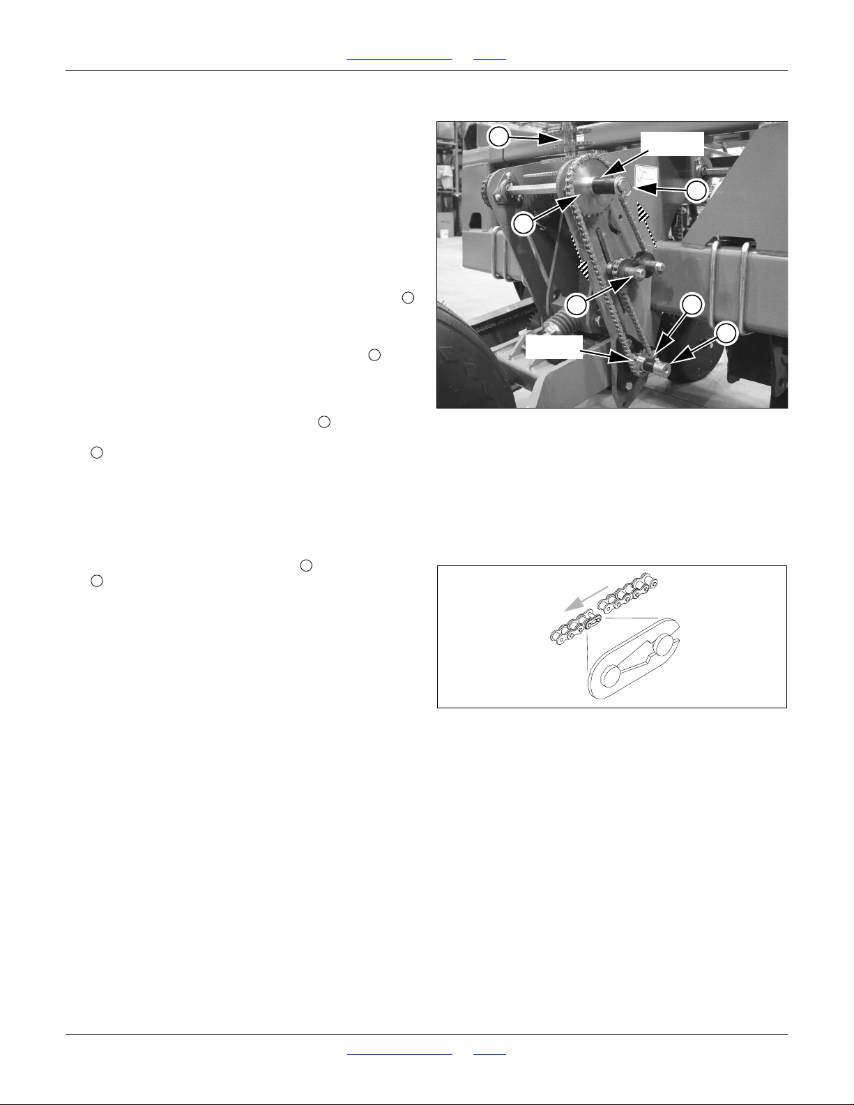
1510HDP, 2010HDP and 2510HDP Table of Contents Index Adjustments
Figure 27
Range Sprockets
22875
DRIVING
DRIVEN
3
4
2
5
1
6
123
4
Figure 28
Chain Clip Orientation
26482
5
6
Range Sprockets
Before setting the Range or Transmission, raise the drill
and rotate the gauge wheels. Check that seed meters,
seed tubes and drives are working properly and free
from foreign material.
Sprockets are identified by tooth counts, for example
“19” or “19T”, stamped on the face of the sprocket.
Examine any mount sprockets before removing pins, as
the needed sprocket may already be mounted.
Refer to Figure 27, which depicts a right side
single-wheel ground drive, without acremeter.
Alternate sprockets are stored on shafts on the top
and side (see Figure 29) of the ground drive.
Refer to Figure 27
8. Loosen the bolt securing the forward idler , and
slide the idler down in its slot. Remove the chain
from any sprockets to be changed. Hang the chain
on the idlers to prevent ground contact.
9. To change the DRIVING sprocket , remove the
cotter pin securing the acremeter hex shaft adaptor
, and then the adaptor and spacer. The adaptor
may have an acremeter installed. If so, set the
assembly where it cannot fall on drill parts or the
ground.
Exchange sprockets, re-install the spacer and the
adaptor. Re-pin the adaptor.
10. To change the DRIVEN sprocket , remove the pin
, the spacers and the sprocket.
Exchange sprockets, re-install spacers and re-pin.
If Transmission does not need changing, put all
loose sprockets on storage shafts and re-pin those
shafts.
Refer to Figure 28
11. Reroute chain over sprockets and idlers. Make sure
open end of chain clip faces away from direction of
chain travel (shown by gray arrows).
12. Move idler into chain so chain has
longest span (see page 111 for chain slack). Tighten
1
in slack in its
4
idler. Re-pin all three shafts.
13. Configure other gauge wheel to match.
Each gauge wheel drives half of the drill. If a chain
breaks or is removed, that drill half does not plant.
Great Plains | 118-245M | 2018-07-18 Table of Contents Index 37
Page 42
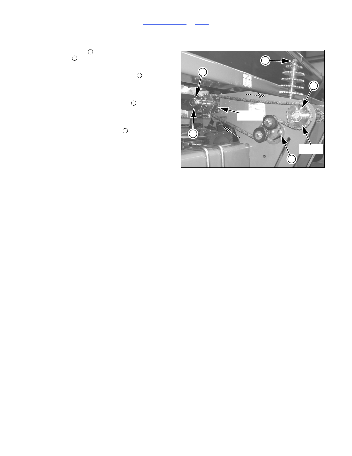
1510HDP, 2010HDP and 2510HDP Table of Contents Index Adjustments
Figure 29
Transmission Sprockets
22876
4
2
3
1
DRIVING
DRIVEN
2
12335
Transmission Sprockets
The DRIVEN shaft of the Transmission is also a
storage shaft .
Refer to Figure 29
14. Loosen the bolt securing the idler plate , and rotate
the idler out of engagement with the chain. Remove
the chain from any sprockets to be changed. Hang
the chain on the idlers to prevent ground contact.
15. To change the DRIVING sprocket , remove the
lynch pin.
Exchange sprockets and re-pin the adaptor.
16. To change the DRIVEN sprocket , remove the pin,
all stored sprockets and the current driven sprocket.
Exchange sprockets, re-install spacers and re-pin.
17. Store all loose sprockets on storage shafts and
re-pin those shafts.
Refer to Figure 28 on page 37
18. Reroute chain over sprockets and idlers. Make sure
open end of chain clip faces away from direction of
chain travel (shown by gray arrows).
19. Rotate idler into chain so chain has
longest span (see page 111 for chain slack). Tighten
idler. Re-pin all three shafts.
20. Configure other gauge wheel to match.
1
in slack in its
4
Checking Main Box Seed Rate
• Great Plains recommends checking singulated
seeding rates (page 39). If you have the optional seed
monitor, it does this for you during planting, and no
extra verification is required.
• Great Plains recommends calibrating volumetric
seeding rates (page 40). The optional seed monitor
can report blockage, but is not a substitute for
calibration.
• Small Seeds and Fertilizer have their own calibrations
(page 42 and page 46). The seed monitor has no
sensors on those delivery tubes.
Singulated rates are precise, when field conditions (nominal slippage) and tire conditions (wear and inflation) are
similar to those used to develop the rate charts. Your
conditions will vary over time. Rate checking also detects
any drill configuration errors.
Volumetric rates are approximate, as volumetric wheels
do not pick and place one seed per cell as singulating
wheels do. Field rates can vary significantly from chart
rates, and only calibration provides the necessary correction, ensuring desired population.
Great Plains | 118-245M | 2018-07-18 Table of Contents Index 38
Page 43
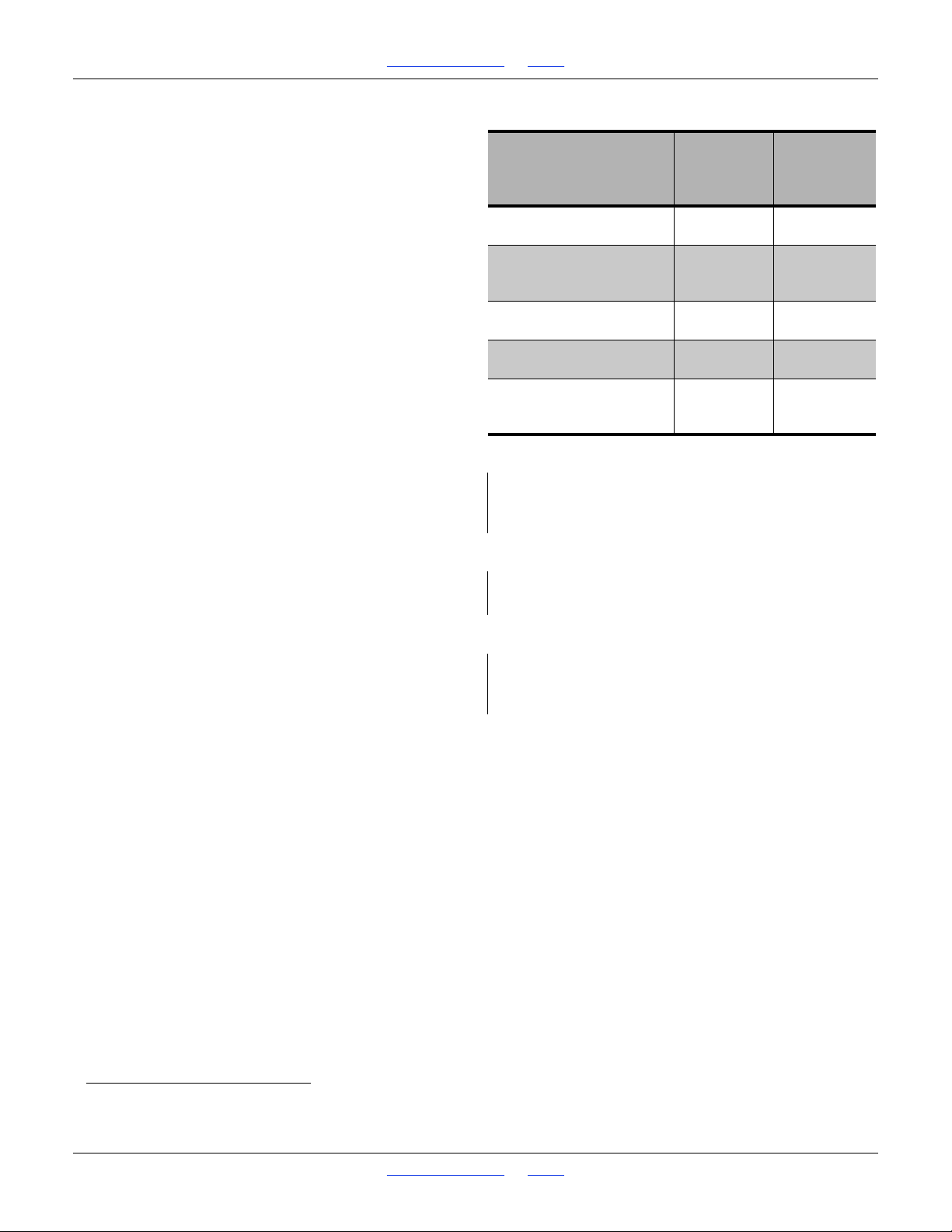
1510HDP, 2010HDP and 2510HDP Table of Contents Index Adjustments
Row Spacing
inches
(cm)
Rows
to
Count
Distance for
1/1000th
Acre
(Hectare)
Distance for
1/200th Acre
(Hectare)
Single Row 7.5in
(19.1cm)
4
17 ft 5in
(13.09m)
N/R
Single Row 10in
Twin Row w/Split
(25.4cm)
3
17ft 5in
(13.09m)
N/R
Single Row 15in
(38.1cm)
2
17ft 5in
(13.09m)
87ft 1in
(65.62m)
Single Row 20in
(50.8cm)
1
26ft 2in
(16.69m)
130ft 8in
(98.43m)
Single Row 30in
Twin Row 30in
(76.2cm)
1 row
1 pair
17ft 5 in
(13.09m)
87ft 1in
(65.62 m)
Example (step 2):
2510HDP-2910 operating as 20in single row
Sample 1 row
Example (step 6):
Plant a distance of 26ft 2in
Example (step 7):
Seed count is 165
Population is 33,000 seeds/ac (165x200)
Checking Singulated Seed Rate
Without a seed monitor, singulated rate checking is done
by sampling actual seed delivery for a few rows and a
short distance.
If using hydraulic drive skip step 1.
1. Using the Seed Rate charts, install the correct seed
meters and wheels, and set the Range and
Transmission sprockets per the chart.
2. Check the sampling table at right for the number of
rows or twin pairs
a
to check. Pick which rows to test
on the drill. Rows in tire tracks are suggested, as
seed is less likely to get buried.
If the seed box is empty, and you have seed corks
available, block adjacent rows. Otherwise, shut off
those rows at their sliding seed tube caps.
3. Prepare a small amount of seed equivalent to
approximately 1/200th acre. Load it over the openers
to be tested.
If seed is already loaded across all rows, shut off the
rows not tested at their sliding seed tube caps (page
53), and disengage those meters at the drive
couplers (page 54).
4. If Seed-Lok seed firmers are installed, lock them up
on the sample rows.
5. If you have lock-up pins available, lock-up the rows to
be sampled (page 56) so that they don’t plant and
bury the seed to be counted.
If pins are not available, at the sample rows, set the
down pressure to minimum (cam out of notch, page
51), and set the opener depth to minimum at the
T-handle (page 65). Seeds will be deposited at or
near the surface.
6. From the sampling table, determine the distance to
plant.
planting speed.
7. Count the number of seeds in the active rows.
Multiply by 200 or 1000, depending on the row length
used for the sample.
Lower the drill and drive forward at proposed
This is your population for one acre (or hectare).
a. Both rows of a twin row are counted as a single row.
Great Plains | 118-245M | 2018-07-18 Table of Contents Index 39
Page 44
1510HDP, 2010HDP and 2510HDP Table of Contents Index Adjustments
Example:
2510HDP-2910 drill, in standard 10in row spacing
Seed: barley
Wheel 403-085D Wheat Wide
Population desired: 108 lbs/ac
(note: nearest chart rate is 106.9)
TotalPopulation = 108
Example (step 1):
Three containers weighing 7 oz. empty
21 = 3 x 7
ContainerWeight = 1.31 lbs total empty weight
Example (step 2):
2510HDP-2910 has 29 rows, 3 used in test
PopulationFraction = RowsToTest / RowsToPlant
0.1034 = 3 / 29
Example (step 3):
Expected population for 3 rows and one acre:
SamplePopulation = TotalPopulation x PopulationFraction
11.2 lbs = 108 x 0.1034
Load about 21 pounds for testing
Example (step 7):
TireRotations = 221/acre; 546/hectare
Example (step 7):
TireRotations = 221/acre; 546/hectare
Example (step 8):
Recommended Planting Speed (mph)
for barley at 108 lbs/ac and 10in row spacing is:
8 mph
Ground Speed - Gauge Wheel rpm
Speed
45678
kph
6.4 8.0 9.7 11.3 12.9
rpm
44 55 66 77 88
Calibrating Volumetric Seed Rate
This procedure is for ground drive. If you have hydraulic
drive, see page 79.
The seed charts are based on 11Lx15 rib implement
tires inflated to factory specifications, operating at chart
speed, and a single variety of clean seed.
Factors including seed size/weight, seed treatments,
field conditions and foreign matter in the seed, cause
variations from chart rates. Check the rate. Some
adjustment may be needed.
1. Record the total empty weight of one or more
containers just large enough to hold the seed from
three row units and one acre (or hectare).
2. Pick which rows to test on the drill. Outside rows are
the easiest to work around.
If the seed box is empty, and you have seed corks
available, block adjacent rows. Otherwise, shut off
those rows at their sliding seed tube caps.
3. Prepare an amount of seed for 3 rows and one acre
(or hectare), plus 10 pounds (or 5 kg). Load it over
the openers to be tested.
If seed is already loaded across all rows, shut off the
rows not tested at their sliding seed tube caps (page
53), and disengage those meters at the drive
couplers (page 54). Shutoff is necessary only for the
box being tested, the drive for the other box is not
operating during the test.
4. Consult the Seed Rate charts, and configure the
Range and Transmission sprockets for your seed,
meter wheel and desired population.
5. Raise the drill. Place the sample containers under
the seed tubes of the rows under test.
6. For the tested drill section, rotate the ground drive
gauge wheel a few turns until meters are filled with
seed and seed is metering consistently from the
seed tubes. Stop, and return the seed to the seed
box. Return empty containers to test rows.
7. In the Appendix of this manual, consult the row
spacing reference data for your drill configuration.
Note the number of tire rotations per acre.
8. In the table at right, note the wheel rpm for the
recommended ground speed from the Seed Rate
chart. Use this rpm for testing. Turning too slowly or
too rapidly has unreliable results compared to actual
planting.
Great Plains | 118-245M | 2018-07-18 Table of Contents Index 40
Page 45

1510HDP, 2010HDP and 2510HDP Table of Contents Index Adjustments
Example (step 10):
Our containers with seed weigh a total of:
13.6 lbs
Example (step 11):
SeedWeight = SampleWeight - ContainerWeight
12.3 = 13.6 - 1.3
Example (step 12):
RowRate = SeedWeight / 3
4.1 = 12.3 / 3
Example (step 13):
SeedRate = RowRate x ActiveRowCount
118.9 = 4.1 x 29
Example (step 14):
116.9 is 10.9 lbs higher than the 108 desired
Subtract the correction from the test chart population:
96 = 106.9 - 10.9
The closest chart rate to 96 is 95.7.
Use the 95.7 settings for the next test run.
9. Rotate the gauge wheel for the number of turns for
one acre or hectare. If you are using standard
spacing, you can use the acremeter to tally acres
simulated.
You can also rotate the gauge wheel jackshaft by
means of a wrench or socket, on the drill side that
does not have the acremeter. When turning the
gauge wheel jackshaft, count tire rotations, as the
axle and jackshaft sprockets are not 1:1
10. Weigh containers with metered seed.
11. Subtract initial empty weight of container(s).
12. Divide by three to obtain rate per row.
13. Multiply by the number of active openers on your drill
to determine total pounds seeded per acre.
14. If this figure is different than desired, compute the
correction required in lbs/ac or kg/Ha. This is
difference between the tested rate and the desired
field rate (not the chart rate used for setup).
In the Seed Rate chart, if the measured rate was too
high, pick a new chart population that is lower by the
error amount.
In the Seed Rate chart, if the measured rate was too
low, pick a new chart population that is higher by the
error amount.
You may want to repeat the calibration procedure if
your results vary greatly from seed rate chart (by
more than the difference between adjacent chart
rows).
When drilling, check seeding rate by noting acres drilled,
amount of seed added to drill and seed level in drill box.
If you are seeding more or less than desired, adjust
seeding rate slightly to compensate for field conditions.
To reduce unnecessary wear, remove chains for any box
drives not used, such as Small Seeds and Fertilizer.
Great Plains | 118-245M | 2018-07-18 Table of Contents Index 41
Page 46
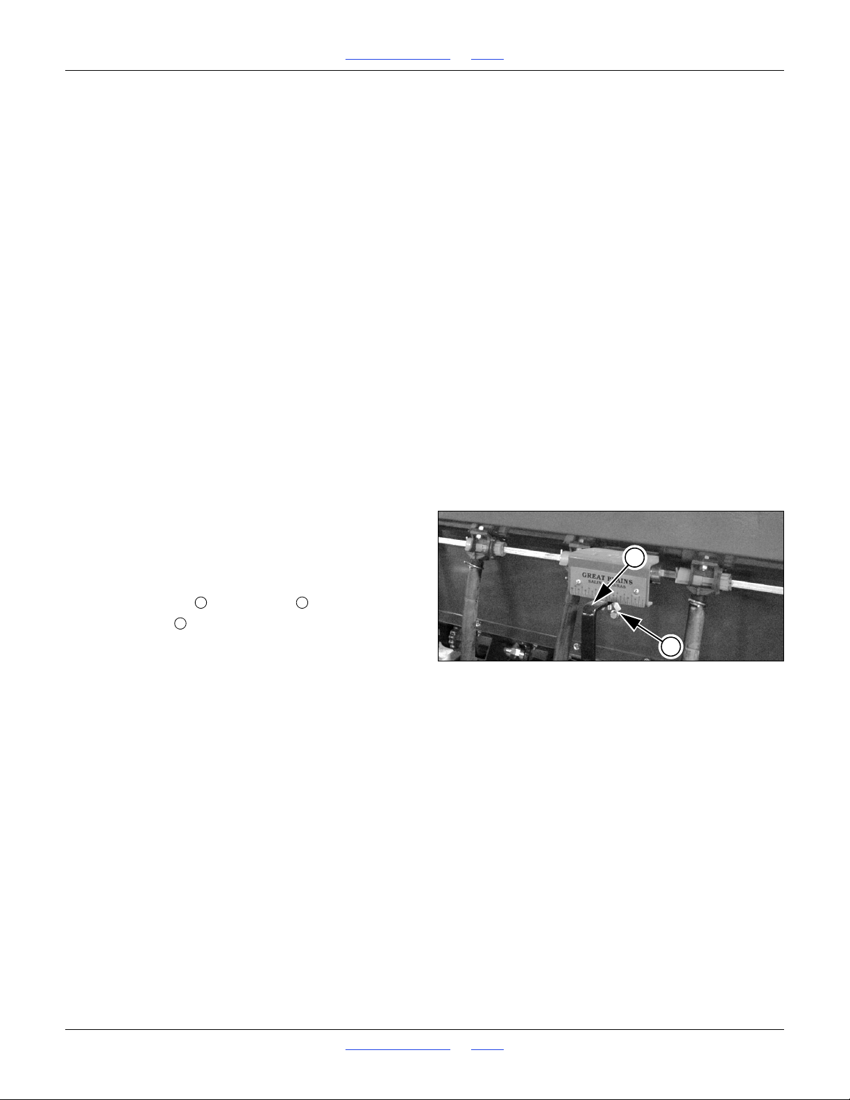
1510HDP, 2010HDP and 2510HDP Table of Contents Index Adjustments
Figure 30 Small Seeds
Seed Cup Lever Adjustment
18511
1
2
122
Small Seeds Attachment Rate
Small seeds attachment box planting rate is controlled
by:
• Seed Rate handle setting
Small seeds rate is independent of the Range and
Transmission sprockets used for main seed box planting.
The small seeds cups also have no doors to adjust.
Before setting the rate, raise the drill and rotate the
gauge wheels. Check that seed meters, seed tubes and
drives are working properly and are free from foreign
material.
The procedure for setting the small seeds box rate is:
1. Disable main box seed meters (see page 53). Shut
off seed flow and disengage meters from drives. Do
not lock up row units.
2. Consult the charts for your crop in the Seed Rate
manual. That provides the initial Rate Handle
settings.
3. Configure Seed Rate handle on one or both sides of
the drill.
4. Calibrate the drill for your specific seed.
5. Set both rate handles identically.
Small Seeds Rate Handle
Refer to Figure 30
Position the small seeds seed cup lever handle to setting
indicated on the Rate Chart in the Seed Rate manual.
To adjust:
1. Loosen wing nut under handle .
2. Slide handle until indicator is about 10 past the
desired value, then move it back to the desired value.
3. Tighten wing nut.
Small Seeds Rate Calibration
You may need to increase seed cup setting for lighter
than average seed or decrease seed cup setting for
heavier than average seed.
The seed rate charts are based on cleaned, untreated
seed of average size and test weight. For seed not
listed on the charts, compare weight and size to those
listed and use a similar setting.
Great Plains | 118-245M | 2018-07-18 Table of Contents Index 42
Page 47

1510HDP, 2010HDP and 2510HDP Table of Contents Index Adjustments
Example (step 1):
Drill: 2510HDP-2910
Seed: Millet
Target population: 5 pounds per acre
Rate Handle from chart:
between 30 and 35, approximately 34
Example (step 3):
Assume 3 empty container each 4.3 oz.
12.9 oz = 4.3 x 3
ContainerWeight = 0.8 pounds
Example (step 7):
Drill: 2510HDP-2910
Tire rotations: 229/acre; 566/hectare
Example (step 10):
Assume container plus seed weighs:
1.25 pounds
Example (step 11):
0.45 = 1.25 - 0.8
SeedWeight = 0.45
SeedWeight TotalWeight ContainerWeight–=
Refer to sample data and formulas at right.
1. Consult the rate chart for your seed.
2. Set rate handle per the earlier instructions.
3. Record weight of one or more light empty containers
just large enough to hold seed metered for one acre
for three rows.
4. Place several pounds of seed over three seed cups
on an outside end of a drill box. Pull seed tubes off of
these three openers and route them to container(s).
5. Raise the drill.
6. Rotate gauge wheel a few turns to confirm that the
seed paths are free from foreign matter, seed cups
are full of seed, and seeds are being metered
consistently. Place seed collected so far back in the
box.
7. In the Appendix of this manual, consult the row
spacing reference data for your drill configuration.
Note the number of tire rotations per acre.
Recommended ground speed for small seeds
planting is 5 mph (8 kph), which corresponds to a
gauge wheel rotation rate of 55 rpm. Use this rpm for
testing. Turning too slowly or too rapidly has
unreliable results compared to actual planting.
8. Rotate the gauge wheel for the number of turns for
one acre or hectare. If you are using standard
spacing, you can use the acremeter to tally acres
simulated.
You can also rotate the gauge wheel jackshaft by
means of a wrench or socket, on the drill side that
does not have the acremeter. When turning the
gauge wheel jackshaft, count tire rotations, as the
axle and jackshaft sprockets are not 1:1
9. Check that the three seed cups have ample seed
coming into them.
10. Weigh metered seed.
11. Subtract initial weight of empty container(s).
Great Plains | 118-245M | 2018-07-18 Table of Contents Index 43
Page 48
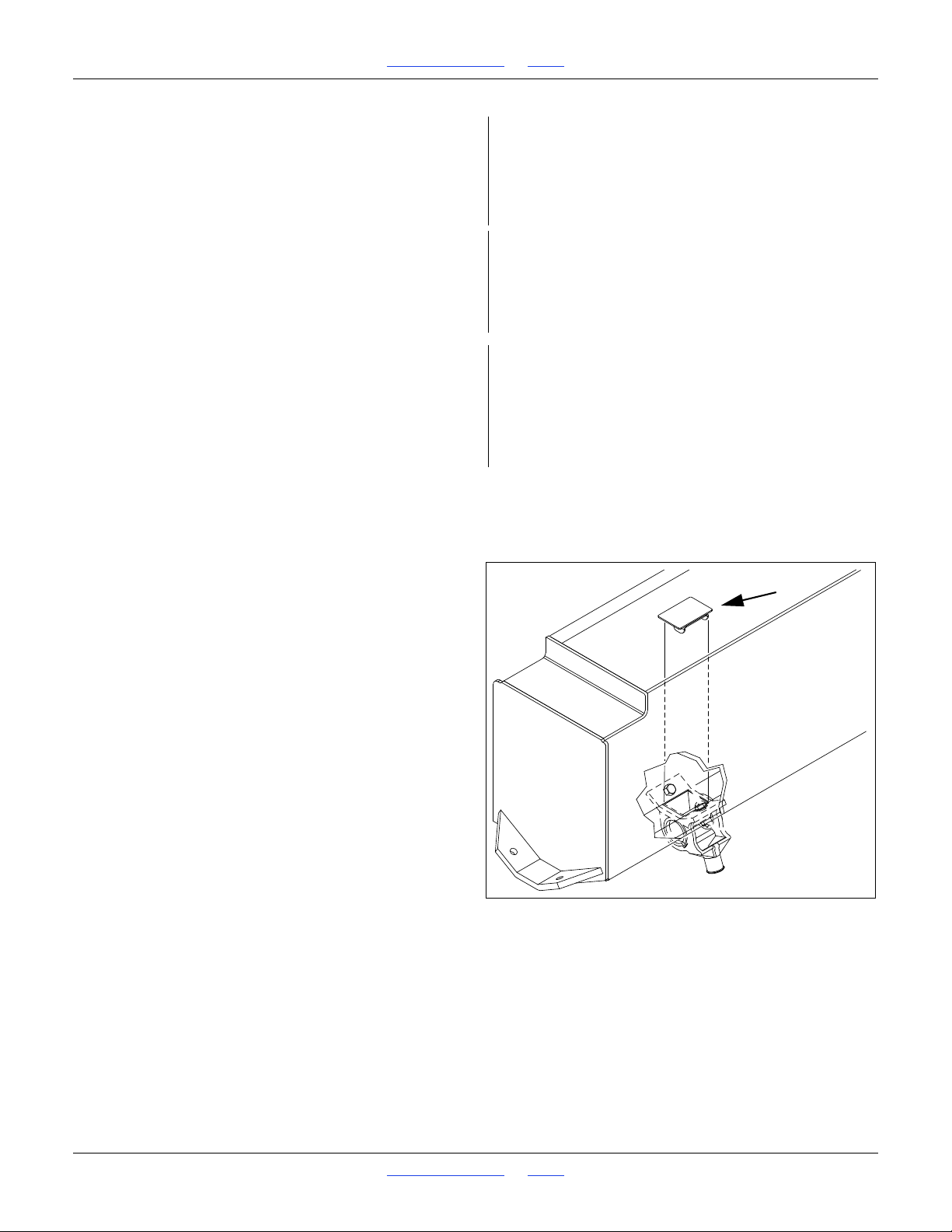
1510HDP, 2010HDP and 2510HDP Table of Contents Index Adjustments
Example (step 12):
0.15 = 0.5
3
PoundsPerCup = 0.15
PoundsPerCup
SeedWeight
3
---------------------------- -
=
Example (step 13):
4.35 = 0.15 x 29
PoundsPerAcre = 4.35
PoundsPerAcre PoundsPerCup OpenerCount=
Example (step 14):
Target was 5.0 pounds per acre.
Test result is 13% low.
Adjust handle up by 4 (13% of 34)
to a Seed Rate Handle setting of:
38
Figure 31
Small Seeds Tube Plug
27407
12. Divide by three to obtain a rate per row.
13. Multiply by the active row count to obtain a measured
seed rate.
14. If this figure is different than desired, set your seed
rate adjustment handle accordingly.
15. If the adjustment was more than 5%, it is advisable
to re-test to confirm that the adjustment achieves the
desired field rate.
16. Once a setting is settled on, configure the other
Small Seeds box to match.
When drilling, check seeding rate by noting acres drilled,
amount of seed added to drill and seed level in drill box.
If you are seeding more or less than desired, adjust
seeding rate slightly to compensate for field conditions.
Small Seeds Row Shut-Off
If alternate row spacing is required for small seeds,
optional plugs are available to block flow inside the seed
box tray. See page 128 for ordering information.
1. Clean out seed. The seed box must be empty prior to
inserting plugs. See “Small Seeds Box Clean-Out”
on page 103.
2. Before installing plugs, inspect the seed boxes for
existing factory-installed plugs. These are blocking
extra unused seed ports. You may want to identify
these plugs with an indelible marker.
3. Insert one plug at each row to shut off. Verify the
seed hose path before inserting the plug, as some
hoses do not make a strictly vertical drop to their row
units.
4. Review seed rate settings and marker extension
prior to planting.
When removing plugs to restore rows to operation, be
sure to not disturb a factory-installed plug.
Great Plains | 118-245M | 2018-07-18 Table of Contents Index 44
Page 49
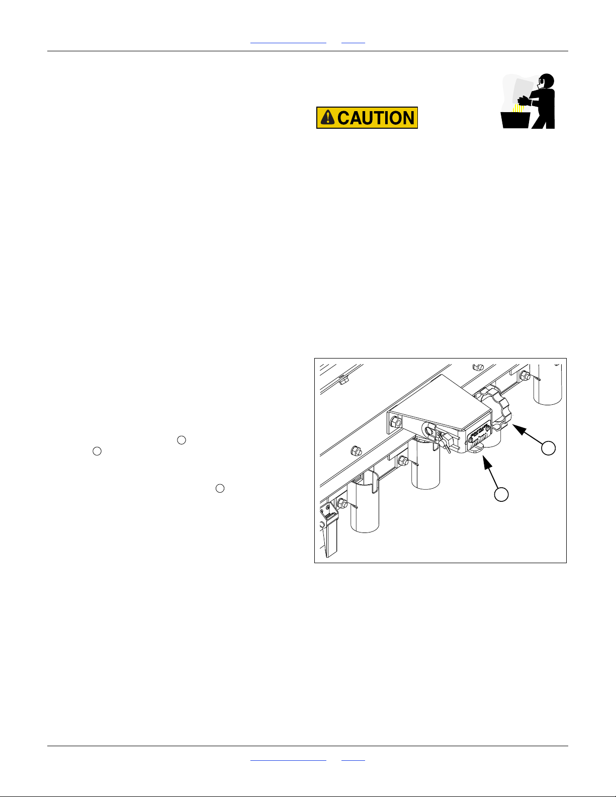
1510HDP, 2010HDP and 2510HDP Table of Contents Index Adjustments
Agricultural chemicals can be dangerous. Improper use can
seriously injure persons, animals, plants, soil and property.
?
Do not use liquid treatments with drill.
?
Read and follow chemical manufacturer’s instructions.
?
Wear protective clothing.
?
Handle all chemicals with care.
?
Avoid inhaling smoke from any type of chemical fire.
?
Never drain, rinse or wash dispensers within 100 feet (30m)
of a freshwater source, nor at a car wash.
?
Store or dispose of unused chemicals as specified by
chemical manufacturer.
?
Dispose of empty chemical containers properly. Laws
generally require power rinsing or rinsing three times,
followed by perforation of the container to prevent re-use.
Figure 32
Fertilizer Rate Adjuster
27256
1
2
122
Fertilizer Rate
Fertilizer rate is controlled by:
• Rate adjuster setting
Fertilizer rate is independent of the Range and
Transmission sprockets used for main seed box planting.
The fertilizer cups have no doors to adjust.
Before setting the rate, raise the drill and rotate the
gauge wheels. Check that meters, tubes and drives are
working properly and are free from foreign material.
The procedure for setting the fertilizer rate is:
1. Know your material density. If it is substantially
different from the material used to generate the
charts, apply a correction factor before selecting the
initial rate from the charts.
2. Consult the fertilizer rate chart for desired
applications density (pounds/acre or kg/hectare).
The chart provides the initial adjuster setting.
3. Configure the adjuster on one or both sides of the
drill.
4. Calibrate the drill for your specific material.
5. Set both rate adjusters identically.
Setting the Fertilizer Adjuster
Refer to Figure 32
Each fertilizer box has its own adjuster, located near box
center. Position the adjuster to the rate from the fertilizer
Chart in the Seed Rate manual.
To adjust:
1. Rotate the adjuster knob located to the right of the
scale . Rotate counter-clockwise to increase rate.
The knob stays at your setting due to springs
clamping a nut at the left end of the shaft.
2. Rotate the adjuster until indicator is about 10 past
the desired value, then move it back to the desired
value.
Great Plains | 118-245M | 2018-07-18 Table of Contents Index 45
Page 50

1510HDP, 2010HDP and 2510HDP Table of Contents Index Adjustments
Example:
Drill: 2510HDP-2910
Desired Application Rate (
ActualRate): 60 lbs/ac
Example (step 1):
A gallon of your material weighs 5.6 lbs
A (U.S.Liquid) gallon is 231 cubic inches or
0.1337 cubic feet
42 = 5.6 / 0.1337
YourDensity = 42
Example (step 2):
1.55 = 65
42
CorrectionFactor = 1.55
CorrectionFactor
StandardDensity
YourDensity
-----------------------------------------
=
Example (step 3):
93 = 60 x 1.55
CorrectedRate = 93
CorrectedRate ActualRate CorrectionFactor=
Example (step 4):
The closest chart rate to 93 is 92.
Use adjuster setting: 50
Example:
Drill and material from examples above
Assume empty ContainerWeight of:
1.1 pounds
Fertilizer Density Correction
The Fertilizer Rate charts in the Seed Rate manual are
based on a
StandardDensity of:
65 pounds/cu-ft or
1.04 kg/liter.
If your material is substantially different, and/or if you
don’t intend to calibrate, calculate a
CorrectedRate before
consulting the rate chart.
1. Obtain your material density from the packaging. If it
is not documented, you will need to weigh a known
volume of it, and convert the results to
pounds-per-cubic-foot or kilograms-per-liter.
2. Compute the correction factor.
3. Apply the correction factor to your desired
application rate.
4. Look up the setting for the
CorrectedRate in the
Fertilizer Rate chart.
5. The
CorrectedRate is used only to obtain an initial
setup for the rate adjuster. Calibrate to your real field
rate (the
ActualRate).
Fertilizer Rate Calibration
Calibration is strongly recommended. Fertilizer density
and granularity can be substantially different from the
material used to generate the chart.
Refer to sample data and formulas at right.
1. Consult the rate chart for your material (after
correcting for density, if that step was completed).
2. Set rate adjuster on one of the drill boxes.
3. Record weight of one or more empty containers just
large enough to hold material metered for one acre
for three rows.
4. Place several pounds of material over three fertilizer
cups on an outside end of a drill box. Pull delivery
tubes off of these three openers and route them to
container(s).
5. Raise the drill.
6. Rotate gauge wheel a few turns to confirm that the
fertilizer paths are free from foreign matter, fertilizer
cups are full, and material is being dispensed
consistently. Place material collected so far back in
box.
Great Plains | 118-245M | 2018-07-18 Table of Contents Index 46
Page 51

1510HDP, 2010HDP and 2510HDP Table of Contents Index Adjustments
Example (step 7):
Drill: 2510HDP-2910
Tire rotations: 229/acre; 566/hectare
Example (step 9):
Assume container plus material weighs:
7.3 pounds
Example (step 10):
6.2 = 7.3 - 1.1
SeedWeight = 6.2
SeedWeight TotalWeight ContainerWeight–=
Example (step 11):
2.1 = 6.2
3
PoundsPerCup = 2.1
PoundsPerCup
SeedWeight
3
---------------------------- -
=
Example (step 11):
49.6 = 2.1 x 24
PoundsPerAcre = 49.6
PoundsPerAcre PoundsPerCup OpenerCount=
Actual Target was 60 pounds per acre.
Result is 17% low.
Change adjuster up by 8.5 (17% of 50)
to a Fertilizer Rate Adjuster setting of:
59
7. In the Appendix of this manual, consult the row
spacing reference data for your drill configuration.
Note the number of tire rotations per acre.
Simulate the ground speed for the intended seeding.
See the table on page 40 for the gauge wheel rpm to
use for that speed.
8. Rotate the gauge wheel for the number of turns for
one acre or hectare. If you are using standard
spacing, you can use the acremeter to tally acres
simulated.
You can also rotate the gauge wheel jackshaft by
means of a wrench or socket, on the drill side that
does not have the acremeter. When turning the
gauge wheel jackshaft, count tire rotations, as the
axle and jackshaft sprockets are not 1:1
9. Weigh metered material.
10. Subtract initial empty weight of container(s).
11. Divide by three to obtain the row rate.
12. Multiply by the number of openers on your drill to
determine total pounds applied per acre.
13. If this figure is different than desired, set your
fertilizer rate adjuster accordingly.
You may want to repeat the calibration procedure if
your results vary greatly from the rate chart.
When drilling, check material rate by noting acres drilled,
amount of material added to drill and material level in drill
box. If you are applying more or less than desired, adjust
rate slightly to compensate for field conditions.
Great Plains | 118-245M | 2018-07-18 Table of Contents Index 47
Page 52
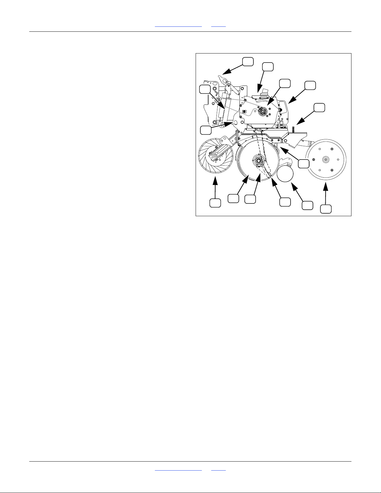
1510HDP, 2010HDP and 2510HDP Table of Contents Index Adjustments
Figure 33
10HD Series Row Unit
27406
1
2
3
4
5
9
10
11
12
12
6
7
8
9
Row Unit Adjustments
Refer to Figure 33
(which depicts a row unit fully populated with all optional
accessories supported for use on at least one 10HDP
model - some models may not support some
accessories)
From front to back, a Great Plains 10HD Series row unit
can include the following capabilities (some optional):
1. Unit-Mounted Coulter (UMC): optional
UMCs cut residue and prepare the soil ahead of the
seed furrow. See page 49 for adjustments.
2. Dual Down Pressure Springs: standard
Each row unit is mounted on the drill via parallel
arms which allow the row unit to independently move
up and down while remaining parallel to the ground.
The adjustable spring provides the force to get the
row unit and attachments into the soil. See page 51
for adjustments.
3. Row Unit Spring Cam: standard
This adjustment sets the down-force used by the row
unit. See “Row Unit Down-Force” on page 51.
4. Row-Unit Lock-Up: holes standard, pins optional
If rows are shut off with seed tube plugs, row unit
wear can be reduced by locking them up. See “Row
Unit Shutoff” on page 53.
5. Disc Blades: standard, 2 per row unit
Double disc blades open a furrow, creating the seed
bed. Spacers adjust the blades for a clean furrow.
See “Disk Blade Adjustments” on page 57.
6. Seed Tube with Shutoff (standard)
Seed flow to a row may be shut off by repositioning
the cap. See “Row Unit Shutoff” on page 53.
7. Seed Meter (standard - choice of models)
A precision or finger pickup meter is standard, with a
choice of wheels or finger sets. See page 60 for
changing meters and wheels. See page 62 for finger
meter adjustments.
8. Drive Coupler
Disengage unused rows during calibration or when
using alternate row spacings. See page 54.
9. Scrapers: (spreader shown)
A lower separator/scraper is standard.
An upper rear carbide scraper is optional.
See page 130.
10. Seed delivery tube: standard
No adjustments are necessary. See page 53 for
seed tube shutoff above meter. Standard tubes
include a seed sensor for the optional seed monitor.
11. Seed firmer:
Reduces seed bounce and aids emergence by
pressing seed gently into the furrow.
for replacement.
Keeton seed firmer (not shown)
Improves seed-soil contact, and provides a stable
arm for a low-rate liquid fertilizer delivery tube. See
“Keeton Seed Firmer Adjustment” on page 64.
Seed-Lok™ firming wheel (shown)
Improves seed-soil contact. See “Seed-Lok™ Seed
Firmer Lock-Up” on page 64.
12. Press wheels: standard (choice of types)
These close the seed trench. The wheels also
support the free end of the row unit, and provide the
primary control over seeding depth. See “Opener
Depth (Press Wheel Height)” on page 65.
Do not back up with row units in the ground. To do so
will cause severe damage and row unit plugging.
A seed flap (not shown) is standard. See page 110
Great Plains | 118-245M | 2018-07-18 Table of Contents Index 48
Page 53
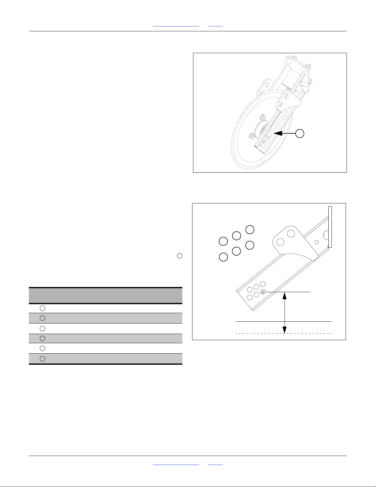
1510HDP, 2010HDP and 2510HDP Table of Contents Index Adjustments
Figure 34
10HD Series Unit-Mounted Coulter
22817
7
Figure 35
Coulter Blade Mounting Holes
23288
1
2
5
4
3
6
7235146
Unit-Mounted Coulter Adjustments
Unit-mounted coulters are optional. See page 129 for
ordering information.
Unit-Mount Coulters are not factory-installed. Check
alignment and depth prior to first use.
Coulter Depth Adjustment
The ideal operating depth for unit-mounted coulters is
1
in above opener depth. Although they may have
4
originally been set to this depth, coulter (and opener)
blades wear with time, and may need adjusting.
Adjusting the coulter depth is accomplished by
re-mounting the coulter blade in one of the six mounting
holes arranged in a staggered pattern in the coulter
bracket.
Refer to Figure 34 and Figure 35
Raise drill before working on coulters. Row unit may be
fully lowered or locked up. Do not attempt to move blade
when the current or new position causes it to contact the
ground during the adjustment. Be careful around the
front end of row units. Coulter blades may be sharp.
To adjust coulter depth:
1. Determine the present opener and coulter depths.
2. Note which bracket hole the coulter is presently
using.
3. Determine which new hole will position the coulter
closer to the
4. Remove the
in Figure 34).
5. Move the blade to the new position. Insert the bolt,
and tighten on the lock washer and nut.
1
in-above depth. See the table below.
4
5
-11 x 4in bolt, lock washer and nut (
8
Hole No.
Depth of (new) coulter blade relative to (new)
opener blades
1in above
5
8in above
1
4in above
0 (factory standard hole)
3
8in below
3
4in below
If a worn coulter cannot be adjusted to satisfactory operating depth, replace the coulter blade.
Great Plains | 118-245M | 2018-07-18 Table of Contents Index 49
Page 54
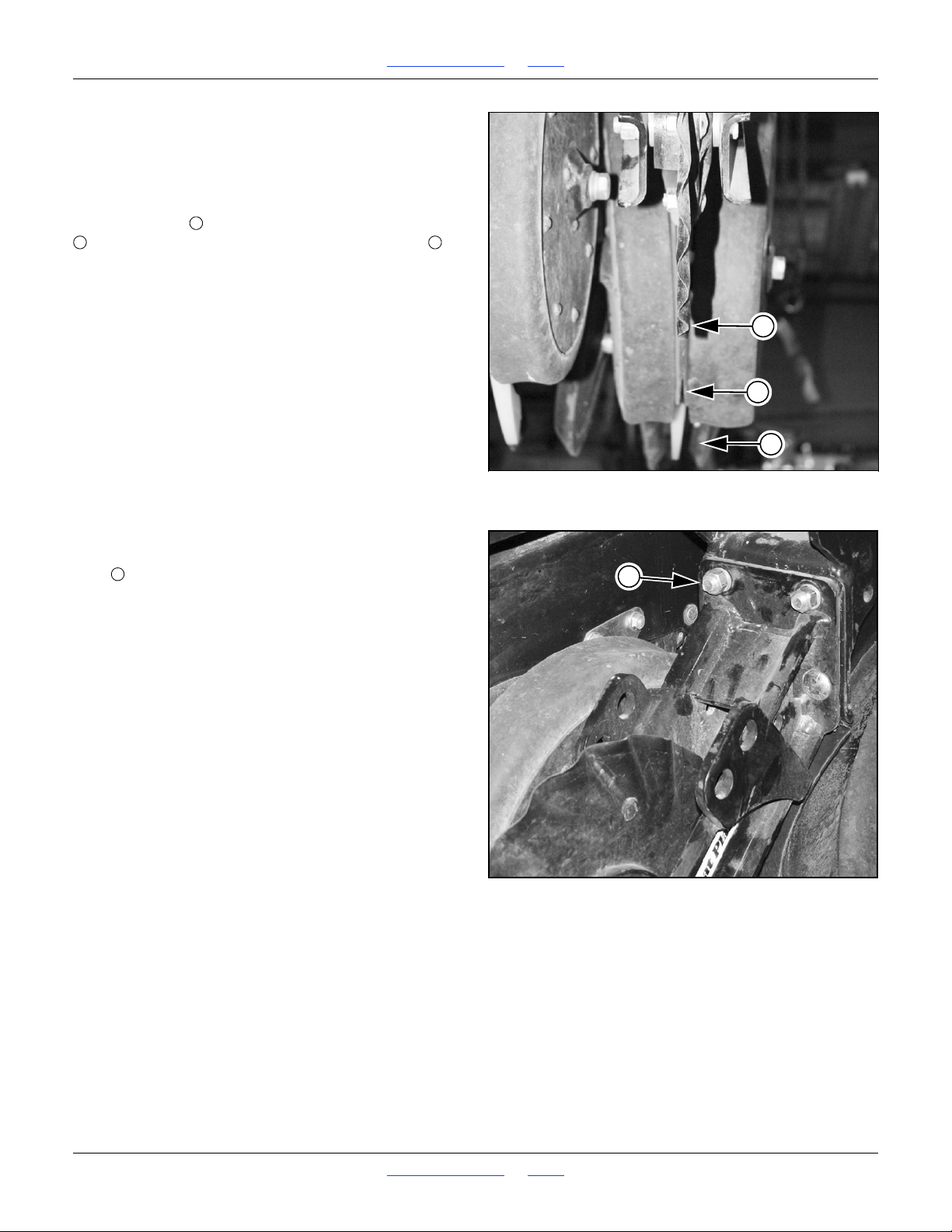
1510HDP, 2010HDP and 2510HDP Table of Contents Index Adjustments
Figure 36
10HD Series Coulter Alignment
26125
1
2
3
123
Figure 37
10HD Series Coulter Mount
26126
4
4
Coulter Row Alignment
Refer to Figure 36
The ideal alignment coulter is for the blade to prepare a
furrow directly ahead of the opener discs.
As a check on coarse alignment, sight along the coulter
blade centerline , the gap between the opener blades
, and the centerline between the press wheels . If
they are clearly out of alignment, either the coulter or the
press wheels (or both) may be in need of adjustment.
The exacting test of correct alignment is field results.
Operate the drill on some test ground (no seed required),
and verify that the opener blades are in the groove
opened by the coulter.
Refer to Figure 37
To adjust unit-mounted coulter alignment, loosen the four
bolts that attach its bracket to the row unit. The holes
on the row unit are slotted, side-to-side, and allow the
coulter bracket sideways and rotational adjustment.
Keep the coulter blade vertical while adjusting.
If the blade cannot be brought into alignment, check that
the blade spindle itself is using the same hole location on
each side of the bracket.
Great Plains | 118-245M | 2018-07-18 Table of Contents Index 50
Page 55
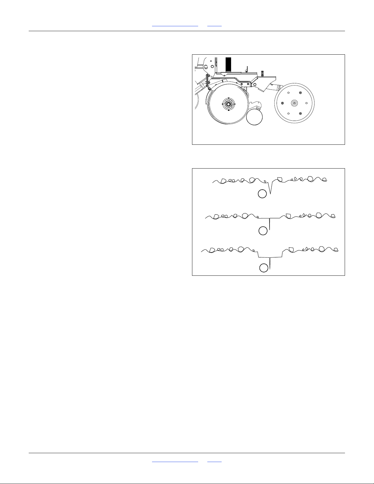
1510HDP, 2010HDP and 2510HDP Table of Contents Index Adjustments
Figure 38
Checking Furrow
27064
{
Inspect Furrow Here
Light or no press wheel
tracks
Insufficient down-force
Increase down-force
Press wheel(s) compress
loose soil only
Ideal
No adjustment required
Press wheel(s)
making deep tracks
Down-force too high
Reduce down-force
Figure 39
Assessing Down-Force
1
2
3
Row Unit Down-Force
Refer to Figure 38
The ideal amount of down-force causes the press wheels
to compress any loose surface soil, but not press a
trench into subsoil.
To assess down-force, operate the drill for a short
distance on typical ground (with or without seeding), and
stop. Leave the drill lowered (row units in ground).
At several row units, inspect the furrow created by the
opener discs and closed by the press wheels.
Be sure to inspect rows both in and out of tire tracks.
Refer to Figure 39
1. If the press wheels are leaving no tracks, or light
tracks, increase down-force.
2. If the wheels are compressing trash and loose soil,
and leaving clear tracks right at the top of the
subsoil, down-force is probably correct and needs no
adjustment.
3. If the wheels are creating a trench into the subsoil,
down-force is too high and needs to be reduced.
Adjusting Row Unit Down Force
The springs allow the row units to float down into
depressions and up over obstructions.
With Unit-Mounted Coulters (or no coulters)
Without frame-mounted coulters, the row unit springs
provide the primary down force for cutting through
residue and opening the seed trench.
Great Plains | 118-245M | 2018-07-18 Table of Contents Index 51
Page 56
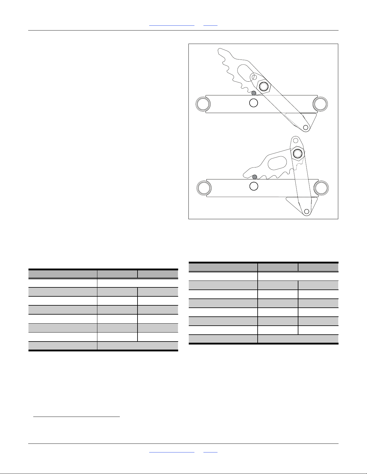
1510HDP, 2010HDP and 2510HDP Table of Contents Index Adjustments
Figure 40: 10HDP:
Row Unit Minimum (one)
and Maximum (six)
27065
1
6
Cam Notch Pounds Kilograms
zero (out of notch) Lock-Up & Maintenance
one 125 55
two 140 60
three 155 70
four185 85
five 215 100
six 245 110
tip Do Not Use
36026
Cam Notch Pounds Kilograms
zero (out of notch) Lock-Up & Maintenance
one 250 115
two 275 125
three 310 140
four 370 170
five 430 195
six 490 220
tip Do Not Use
31452
10HDP Series Down-Pressure
Refer to Figure 40
An adjuster cam sets row unit spring down pressure
individually for each row unit. This is useful for
penetrating hard soil and planting in tire tracks.
The notes in the left table below are based on a drill
without coulters. About 120 pounds (54 kg) of the
down-force is the weight of the row unit itself. The
additional force is due to the springs lifting against the
mass of the drill.
Test, without seeding, in your conditions, to determine
optimal down-force settings.
To adjust down pressure, use an adjustable or open-end
1
1
8inch (29 mm) wrench.
1. Raise the drill. Although this adjustment can be
made with the drill lowered, the springs will be in
tension, and will require more effort. The extra force
required may also damage tools.
2. Put tractor in Park and shut it off.
3. Position wrench on hex nut weldment.
4. Pull upper spring link back.
5. Move the adjustment cam to the new setting on the
spring adjust bar.
2-Spring 10HD Cam Down-Force Settings
These settings apply to 2009+ drills, or updated older
These settings apply to older drills, not yet updated
have four parallel arm springs per row.
drills, that have two parallel arm springs per row.
4-Spring 10HD Cam Down-Force Settings
With 4-spring rows, do not set all rows so high that
planting becomes uneven or gauge wheels lift off
ground.
a. Contac your Great Plains dealer for update kit information.
Great Plains | 118-245M | 2018-07-18 Table of Contents Index 52
a
, that
Page 57
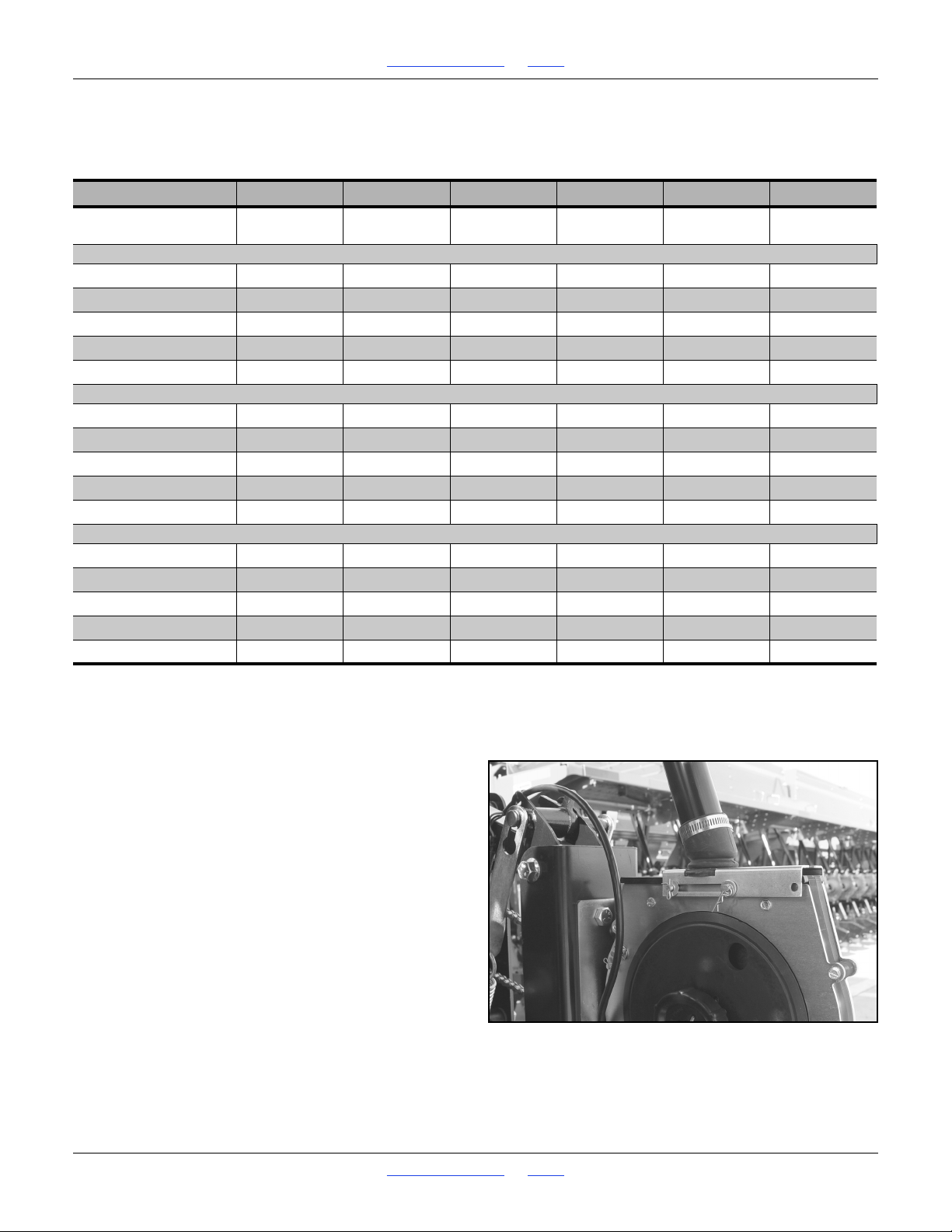
1510HDP, 2010HDP and 2510HDP Table of Contents Index Adjustments
Figure 41
Rear Meter Flow Open
22853
Available Cam Settings
Cam notch “0” (out of notch) is for maintenance only.
Never set the cam beyond “6” (do not use the tip).
1 2 3 4 5 6
Down-Force at Opener
Discs
15-Foot Models
1510HDP-12TR 444
1510HDP-1315 4 4
1510HDP-1910 4
1510HDP-19TRS 4
1510HDP-2475
20-Foot Models
2010HDP-16TR 444
2010HDP-1715 4 4 4
2010HDP-2510 4
2010HDP-25TRS 4
2010HDP-3275 4
25-Foot Models
2510HDP-2015 444
2510HDP-20TR30 4 4 4
2510HDP-2910 44
2510HDP-29TRS 4 4
2510HDP-4075 4
a. Operating all installed rows at this setting requires nominal extra weight, such as dual markers.
b. Operating all installed rows at this setting requires modest extra weight, such as a weight kit.
c. Operating all installed rows at this setting requires substantial extra weight, such as an accessory hitch.
250 lbs
(113 kg)
a
Note
275 lbs
(125 kg)
a
Note
a
Note
b
Note
a
Note
a
Note
b
Note
c
Note
310 lbs
(141 kg)
a
Note
b
Note
b
Note
c
Note
b
Note
b
Note
c
Note
a
Note
a
Note
c
Note
370 lbs
(168 kg)
a
Note
a
Note
c
Note
c
Note
c
Note
a
Note
b
Note
c
Note
c
Note
c
Note
a
Note
a
Note
c
Note
c
Note
c
Note
430 lbs
(195 kg)
b
Note
c
Note
c
Note
c
Note
c
Note
c
Note
c
Note
c
Note
c
Note
c
Note
c
Note
c
Note
c
Note
c
Note
c
Note
490 lbs
(222 kg)
c
Note
c
Note
c
Note
c
Note
c
Note
c
Note
c
Note
c
Note
c
Note
c
Note
c
Note
c
Note
c
Note
c
Note
c
Note
Row Unit Shutoff
When operating with non-standard row spacings, it is
necessary to at least stop the seed flow to the unused
rows. You may also want to take other steps to reduce
wear of components on the unused rows.
Review marker extension if changing row spacing.
Seed Tube Shutoff
Both Great Plains precision and finger pickup meters
have a sliding cap which can be moved and pinned to
prevent seed flow into the meter. Cap shutoff can be
engaged with seed loaded or seed box empty.
Cap shutoff does not prevent the seed tube above it from
filling with seed. To keep the unused seed tubes empty,
use seed tube plugs or seed box baffles.
Refer to Figure 41, which depicts a rear precision
meter with the cap in the normal (open) position.
For shutoff, caps on rear meters move forward, and caps
on front meters move to the rear.
Great Plains | 118-245M | 2018-07-18 Table of Contents Index 53
Page 58
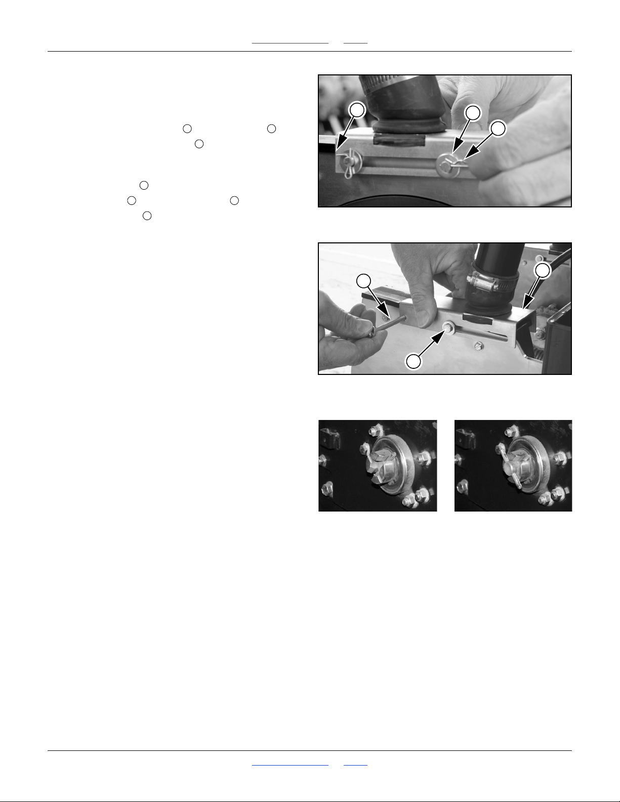
1510HDP, 2010HDP and 2510HDP Table of Contents Index Adjustments
Figure 42
Remove Cap Pin
22854
1
3
2
1234564
Figure 43
Cap to Shutoff
22855
4
5
6
Figure 44
Meter Drive Coupler
Engaged (left) / Disengaged (right)
26171
26172
When both pins are in the cap slots, the meter is open
to seed flow. When one pin is in the slot, and the other
in the cap hole, the meter is closed to seed flow.
Refer to Figure 42, which depicts a rear meter
1. Remove the retaining clip and the washer .
2. Do not remove the cotter pin . It secures a fixed pin
that always remains in place.
Refer to Figure 43, which depicts a rear meter
3. Remove the pin .
4. Slide the cap toward the fixed pin .
5. Re-insert the pin and secure with washer and clip.
6. If seed is already loaded, perform a meter clean-out
(page 106 or page 108) and return the recovered
seed to the seed box.
7. If you don’t intend to disconnect the meter chain, you
can remove a precision meter wheel to reduce wear.
The meter itself, however, must be installed and
coupled to prevent the chain from causing machine
damage.
8. Repeat step 1 through step 7 for each meter to be
disabled.
Disengage Meter
To prevent seed metering from one or more meters, for
example for calibration or altered row spacings, you can
uncouple the meter from the meter drive at the drive
coupler.
At the back (left side) of the drive plate, there is a cross
pin at the end of the drive bearing assembly. In normal
operation, this pin is in the deeper detents.
To disable a meter, pull the cross pin away from the
meter. Rotate it 90 degrees and release it into the
shallow detents.
Do not rely exclusively on the drive coupler to shut off a
row. Use the sliding cap as well, if not also tube corks or
baffles.
When re-engaging drive coupler, it is not necessary to
take steps to ensure the cross pin is fully seated in the
deep detents. It automatically seats when drive
operation commences.
Great Plains | 118-245M | 2018-07-18 Table of Contents Index 54
Page 59
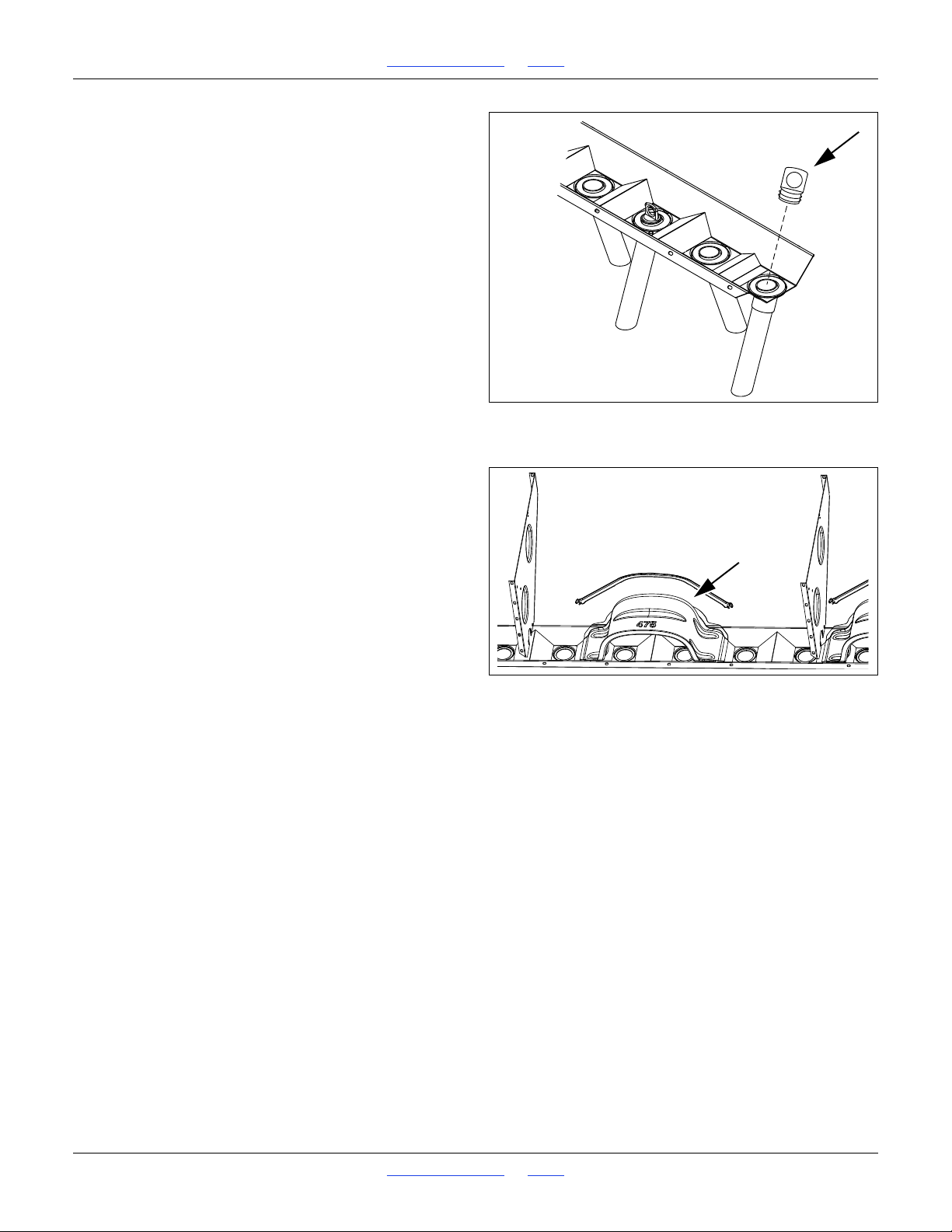
1510HDP, 2010HDP and 2510HDP Table of Contents Index Adjustments
Figure 45
Seed Tube Cork
26226
Figure 46
Seed Box Baffle
20331
Seed Box Tube Cork
Refer to Figure 45
To prevent seed from entering the tubes of unused rows,
optional seed tube corks may be inserted prior to seed
loading.
if a plug is installed, it is not necessary to shut off the
seed meter at the cap.
See page 126 for ordering information.
These corks do not divert seed to open rows, so a small
amount of seed will go unplanted. To prevent seed from
piling at unused rows, baffles (next topic) are available
for some alternate row spacings.
If using baffles, kits include seed tube corks for rows
which cannot accept a baffle (near box partitions and
ends). Corks are unnecessary under baffles.
Seed Box Baffles
Refer to Figure 45, which depicts a baffle converting
several 7.5in single-rows into 30in twin-rows.
Optional baffle packages prevent both seed flow into
unused rows, and seed build up above unused rows.
Baffles must be installed prior to seed loading.
If baffles are used, seed tube corks and seed meter
shutoff are unnecessary on the baffled rows.
For installation and use of baffles, consult the manual
supplied with the kit.
Great Plains | 118-245M | 2018-07-18 Table of Contents Index 55
Page 60
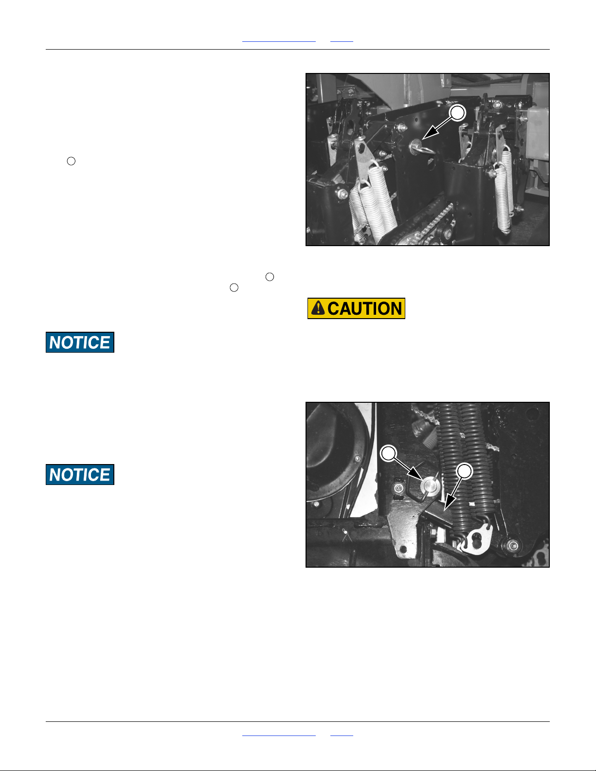
1510HDP, 2010HDP and 2510HDP Table of Contents Index Adjustments
Do not lift a row unit by hand. The weight of the unit, plus the
spring force (even at minimum) is too great (plus, a free hand
is needed for pinning). Even with multiple people lifting, hand
lifting is unsafe - there are numerous sharp edges, and the row
unit will snap down violently if a grip is lost.
Figure 47
Lock-Up Pin Storage
22517
1
123
Figure 48
Row Lock-Up
21981
2
3
Row Unit Lock-Up
Wear of ground-contact components of unused rows can
be minimized by locking up a row unit. Lock-up requires
use of one optional pin (part number is 805-033C) for
each row locked up.
Refer to Figure 47
When not in use, lock-up pins are normally stored in a
hole at the top of the opener mount.
It is generally easier to lock up a rear row unit.
1. Raise the drill. Although this adjustment can be
made with the drill lowered, the row unit springs
would be in tension, and require more effort. The
extra force may also damage tools.
2. Set the down pressure springs be set to the
minimum setting, per the instructions on page 51.
Refer to Figure 48
3. Raise the row unit high enough that the hole for
the pin is above the lower parallel arm :
a. use a hoist at the rear of the shank,
b. use a jack under the shank extension, or;
c. place a block under the row, and lower drill.
Do not pin the row unit while it is in the lowered position. If
the pin is inserted below the parallel arm, unit damage will
occur when planting begins.
4. Remove the pin from the storage hole and insert and
secure it in the lock-up hole.
5. Lower row unit. Parallel arm rests on lock-up pin.
6. Uncouple meter drives for the locked-up rows. Pull
shaft out and park pin in shallow detents (page 54).
Do not disable meters by removing them, unless you also
completely remove the chain, or the chain will cause machine
damage.
7. Repeat for all rows needing lock-up.
8. Reset marker extension (page 25).
9. Reset seed monitor active row pattern and row
spacing to avoid nuisance alarms.
Great Plains | 118-245M | 2018-07-18 Table of Contents Index 56
Page 61
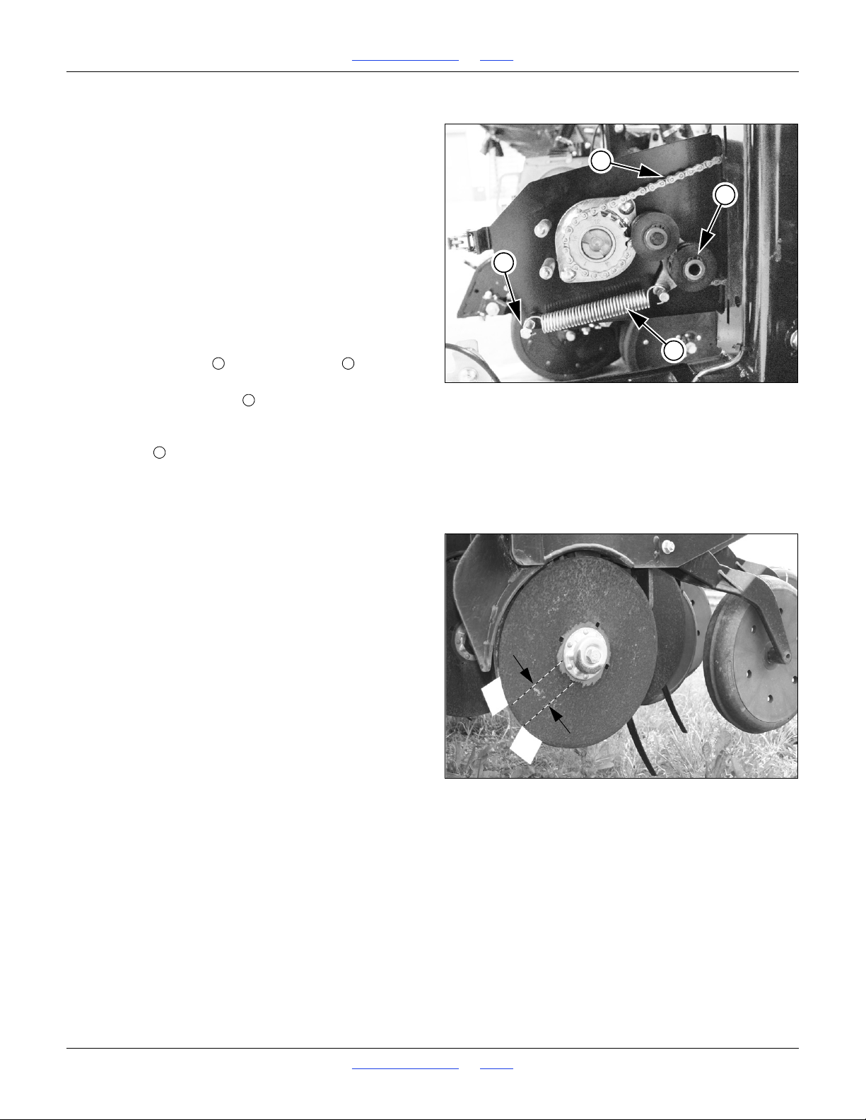
1510HDP, 2010HDP and 2510HDP Table of Contents Index Adjustments
Figure 49
Meter Drive Chain
22868
1
2
3
4
1
234
Figure 50
Checking Disk Contact
26447
Shutoff: Remove Seed Meter and Drive
The meter drive chain of an unused row unit still
operates, even if the row is locked-up, seed flow shut off
and meter wheel disengaged.
To minimize wear on the sprockets, chain and idlers of
unused rows, remove the chain completely. If the chain is
removed, you may also remove the seed meters on
unused rows.
At each row to be deactivated:
1. Install seed corks or baffles to block upper seed
tubes.
2. Remove meters (see page 59). Leave the lower
sliding seed tube connected to the meter.
Refer to Figure 49
3. Lift the idler spring off the lower post . Store the
spring with the meter.
4. Rotate idler assembly out of engagement with
chain.
5. Remove the clip joining the chain ends, and remove
the chain . Store the chain with the meter.
Do not leave the chain on the driving sprocket. Even with
idlers disengaged, meter removed, and/or the chain off
the driven sprocket, machine damage will occur.
Disk Blade Adjustments
Opener disc angle and stagger is not adjustable, but
disc-to-disc spacing is, and may need attention as discs
experience normal wear. Spacers will need to be reset
when blades are replaced.
Refer to Figure 50
The ideal spacing causes the blades to be in contact for
about one inch. If you insert two pieces of notebook
paper between the blades, the gap between them should
be 0 to 1.75in (0-4.4cm).
If the contact region is significantly larger or smaller (or
there is no contact at all), it needs to be adjusted by
moving one or more spacer washers. If the contact
region varies with blade rotation, one or both blades is
likely bent and in need of replacement.
Great Plains | 118-245M | 2018-07-18 Table of Contents Index 57
Page 62
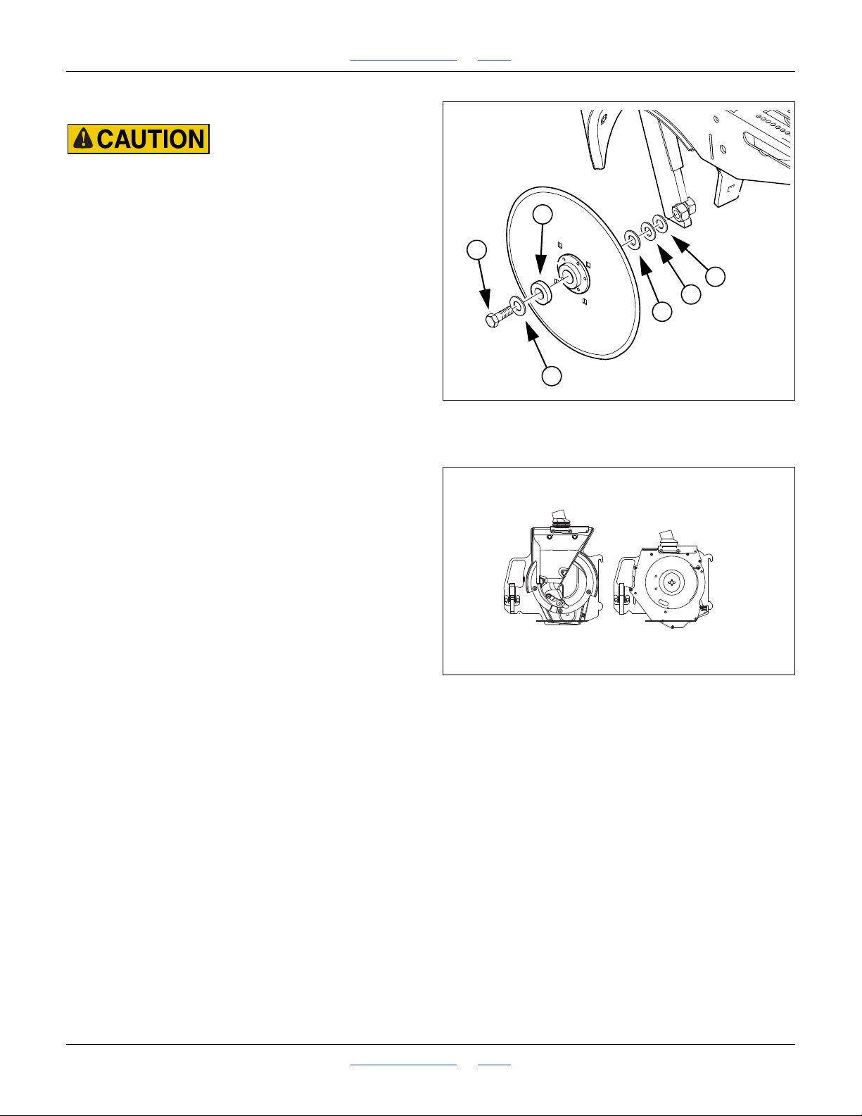
1510HDP, 2010HDP and 2510HDP Table of Contents Index Adjustments
Figure 51
Adjusting Disk Spacers
26385
2
1
3
3
3
3
Figure 52
Adjusting Disk Spacers
26229
Adjusting Disc Contact
Row unit disk blades may be sharp. Use caution when making
adjustments in this area.
Refer to Figure 51
1. Raise the drill and install the transport locks.
2. Remove the bolt retaining the opener disc on one
side. Carefully remove the disc, noting how many
spacers are outside the disk and inside the disk. Do
not lose the hub components and spacer washers.
3. To reduce the spacing between the discs (the normal
case), move one spacer washer from the inside to
the outside of the disc.
4. Re-assemble and check disc contact.
Meter Adjustments
10HDP drills support 10 Series Precision and Finger
Pickup meters. You can change between meter types as
operations require.
• Great Plains precision seed meters offer a choice of
singulating and volumetric seed wheels, often with
several cell counts for coarse selection of population.
See page 59 for changing wheels. There are no
other adjustments required.
• Finger pickup meters are available with 6 or 12
fingers.
Finger meters have a brush adjustment to obtain the
most consistent pickup of seed. See page 62 for
brush settings.
They can also be synchronized for precise seed
stagger in twin row operations. See “Sprocket
Indexing (Stagger)” on page 63.
Great Plains | 118-245M | 2018-07-18 Table of Contents Index 58
Page 63
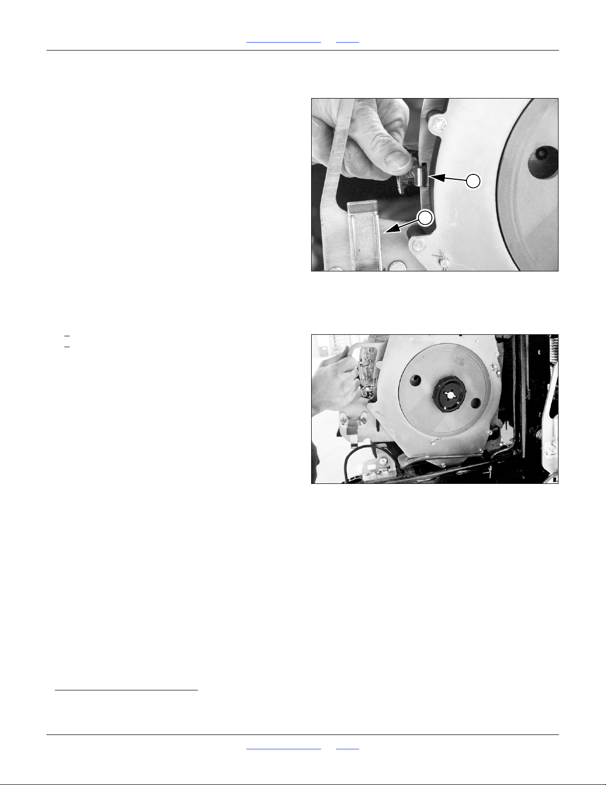
1510HDP, 2010HDP and 2510HDP Table of Contents Index Adjustments
Figure 53
Remove Meter: Latches
22865
1
2
Figure 54
Remove Meter
22867
Changing Meters
If seed is loaded, it will be necessary to unload it before
changing meters, as there is no way to stop seed flow
when a meter is disconnected from the upper drop tube.
See “Main Seed Box Clean-Out” on page 103.
1. Clean out meters to be removed. See page 106 or
page 108.
If precision wheel is not free of all seed, wheel
removal is much more difficult, as pocketed seeds will
shear against meter parts.
Refer to Figure 53
2. Release upper latch, and swing drive plate out until
meter shaft can spin freely.
3. Release lower latch.
Refer to Figure 54
4. Lift up and remove meter, along with the lower
section of the sliding seed tube.
5. Remove the lower section of sliding seed tube from
the cap of the meter just removed.
6. Note whether the meter just removed is:
/
a rear or mid meter, with tube tilted forward, or
\
a front meter, with tube tilted to the rear.
Refer to Figure 55
7. While the meter is removed, inspect the meter drive
components, and apply any needed lubrication to the
chain.
8. Select an alternate meter to install. Select one with
the sliding cap grommet having the same tilt
orientation as the meter just removed.
If the alternate meters are brand new, they may all
have their caps set the same (typically, tilted to rear).
if so, remove both sliding cap pins on half
a
the meters
and reverse the caps. Be sure to use the cotter pin to
secure the cap pin in the slotted hole of the cap.
a. For an odd number of rows, a “mid” row is treated as a rear row (cap tilted forward).
Great Plains | 118-245M | 2018-07-18 Table of Contents Index 59
Page 64
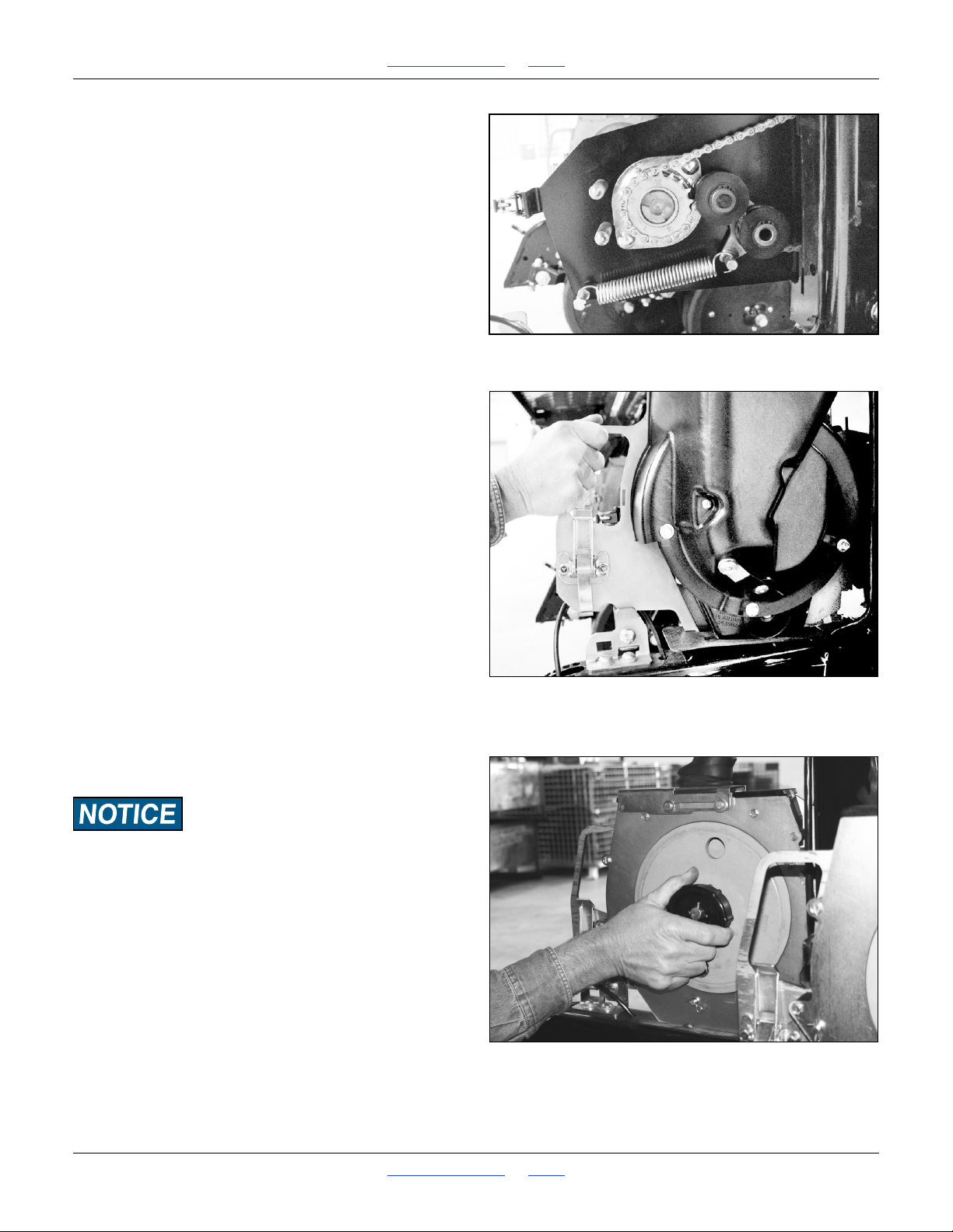
1510HDP, 2010HDP and 2510HDP Table of Contents Index Adjustments
Figure 55
Inspect Meter Drive
22868
Figure 56
Install Meter
22869
Figure 57
Wheel Retainer
22872
9. Insert the lower section of the sliding seed tube in
the cap of the alternate meter.
Refer to Figure 56
10. Install the alternate meter and lower sliding seed
tube.
11. Engage the upper latch. Make sure the tapered
line-up pins near drive sprocket engage completely
in line-up holes.
12. Engage the lower latch.
Changing Precision Seed Wheels
Use the same wheel part number in all active rows.
Wheels for 10HDP precision meters are green in color.
Although similar in appearance, Great Plains wheels in other
colors are not compatible with 10HDP meters. Use only green
wheels in 10HDP meters.
1. Shut off seed flow to the meters with the sliding cap.
See “Seed Tube Shutoff” on page 53.
2. Clean out meters. Leave clean-out doors open. See
page 106 or page 108.
Refer to Figure 57
3. At each meter, push in on the wheel retainer and turn
it until the cross pin is out of the detents and in the
slots.
Great Plains | 118-245M | 2018-07-18 Table of Contents Index 60
Page 65
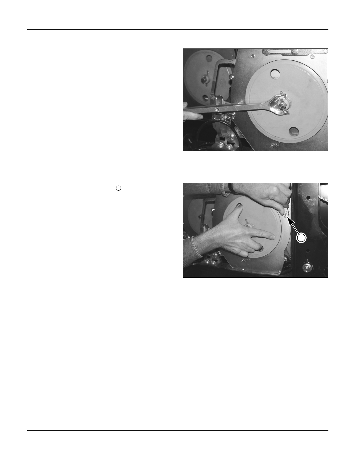
1510HDP, 2010HDP and 2510HDP Table of Contents Index Adjustments
Figure 58
Pry Wheel
22873
Figure 59
Install Wheel
22874
1
1
4. Remove retainer and spring.
Refer to Figure 58
5. Using the special tool stored under the walkboard,
carefully pry the wheel out about
1
in (6.4mm).
4
6. Spin the wheel counterclockwise to remove any
remaining seed.
7. Inspect the interior of the meter for trash, damage
and meter slide wear. Some wear on the top of the
slide is normal. Excess wear is cause for
replacement of the slide (see page 105).
Refer to Figure 59
8. Push meter slide retaining pin forward in its slot.
9. Place alternate meter wheel on shaft and seat in
meter.
10. Place spring and retainer on meter wheel shaft.
11. Push retainer in, rotate 90 degrees, and release so
that cross pin seats in detents.
12. Close clean-out door.
Great Plains | 118-245M | 2018-07-18 Table of Contents Index 61
Page 66
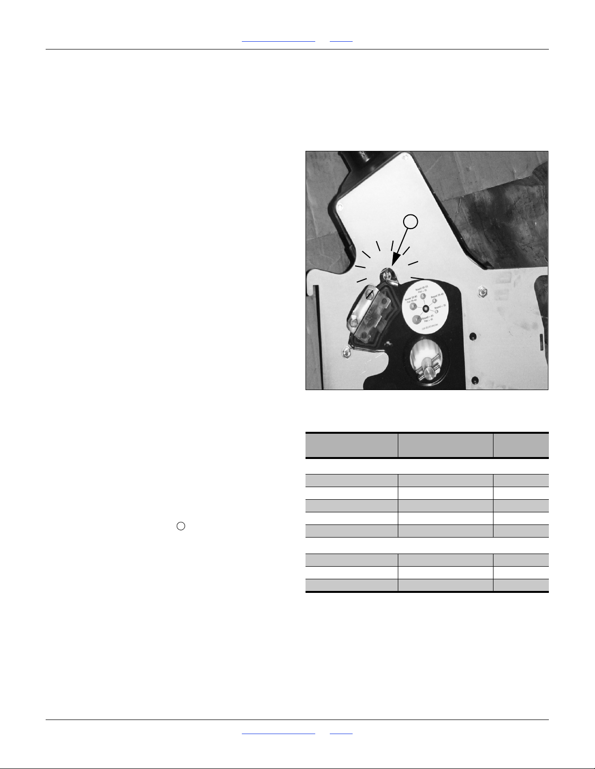
1510HDP, 2010HDP and 2510HDP Table of Contents Index Adjustments
Figure 60
Finger Meter Brush Lever
25276
Bag Weight
(80,000 seeds)
Seeds Per
Pound
Brush
Setting
Rounds
65 lbs 1230 or less 1
65 to 55 lbs 1230 to 1450 2
55 to 45 lbs 1450 to 1780 3
45 to 35 lbs 1780 to 2300 4
35 lbs 2300 or more 5
Flats
45 lbs 1780 or less 1
45 to 35 lbs 1780 to 2300 2
35 lbs 2300 or more 3
5
1
4
3
2
L
L
Finger Meter Adjustments
The finger pick up meter has an adjustable brush, and
alternate inserts are available for the backing plate. The
brush has been pre-set to the optimum setting for most
seed sizes. The factory-installed insert is the “A” insert.
Optimum planting speed is 4
1
to 5 miles per hour (7.2 to
2
8 kph). Excess speed results in poor spacing
performance due to seed tube bounce. Excess speed
may also result in improper depth control due to row unit
bounce.
Always pay attention to your planter monitor. Compare
actual seed usage to your estimates.
Fine-tune your planter by thoroughly checking all key
components including: seed tubes, chains, sprockets,
tire pressure, seed monitor, double disk openers, gauge
wheels, seed firmer, closing wheels, parallel arms, and
the row unit itself.
Finger Meter Brush Adjustment
The brush reduces or eliminates “doubles” (delivering
two seeds per finger), but if set too aggressively can
cause “skips” (delivering no seed on some fingers). As
needed, adjust for minimal doubles and skips.
These instructions describe the current finger pickup
meter shipped with new Great Plains planters, which
has an integrated adjustment lever for the brush. If
you have added pre-existing finger meters after
purchase, there is some chance that you may have
the previous model meter, adjusted by screwdriver
rather than lever. If so, rely on counting detents to
determine the setting. Not all have 9 detents.
Refer to Figure 60
The adjustable brush provides additional flexibility to
accommodate a wide range of seed sizes. Use lever (L)
to gently rotate the brush into position.
The settings range from 1 to 5 with detents at each half
step, for a total of 9 detents. The factory default setting is
1
2
. Although the numbers are molded into the meter
2
housing, only “1” and “5” may be visible. To ensure
consistency, rotate the lever fully counter-clockwise
(1), and count detents as you advance it to the desired
setting.
Use the general guidelines in the table at right to adjust
the brush position to your seed size and shape. The
numbers listed correspond to the numbers printed on the
outer housing of your meter. If there is a decal on your
meter, its units are seed size in pounds per 80,000 seed
bag.
Great Plains | 118-245M | 2018-07-18 Table of Contents Index 62
Page 67
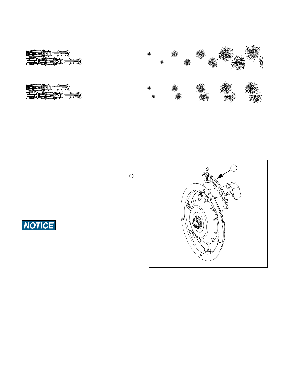
1510HDP, 2010HDP and 2510HDP Table of Contents Index Adjustments
••
•••
•••
•••
Indexed - deliberate pair spacing provides maximum plant separation
Non-Indexed - arbitrary pair spacing
Figure 61
Finger Meter Insert
22908
1
1
Sprocket Indexing (Stagger)
If you are planting:
• finger-metered,
• twin-row crops,
1
• at seed interval spacings above 6
inches,
2
you can synchronize each pair of adjacent meters in a
twin row so that you achieve the maximum seed-to-seed
spacing between the units of the pair.
Refer to the Seed Rate manual for details.
Finger Meter Inserts
Refer to Figure 61
The backing plate is equipped with an “A” insert . In
tests, this insert provides the best performance in most
seed sizes. However, there are two alternative inserts
that can be used. Before changing to a different insert,
please consult with a Great Plains service representative
for a recommendation.
The identification of the insert type is molded into the
back of the insert.
Be cautious in using seed treatments, additives, and other
chemicals when possible. They can cause meter performance
problems and premature wear to meter parts. Avoid the use of
graphite with the precision meter. If graphite must be used, use
Precision™ Planting graphite or Great Plains graphite which
is less abrasive. Generally, seeds coated with Maxi or similar
coatings, such as Captan, benefit from graphite. Always store
meters in a dry, secure place. Moisture, temperature,
nest-building insects and rodents can create problems. Always
pay attention to your seed monitor and operating manual.
Monitor the amount of seed you are planting compared to your
expectations. Always investigate abnormalities!
Great Plains | 118-245M | 2018-07-18 Table of Contents Index 63
Page 68
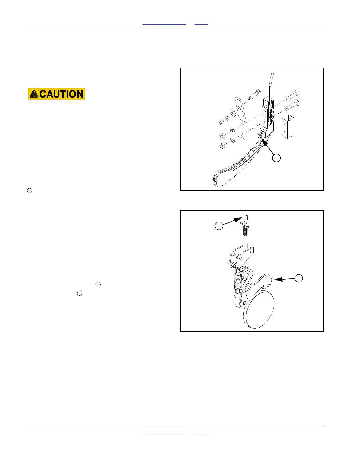
1510HDP, 2010HDP and 2510HDP Table of Contents Index Adjustments
Figure 62
Keeton Seed Firmer
26390
1
1
Figure 63
Seed-Lok™ Lock-Up
27072
2
1
1
2
Seed Firmer Adjustments
10HD Series row units include a seed flap, or one of two
optional seed firmers.
The seed flap requires no adjustment, but may need to
be replaced if worn, and may need to be shortened if an
optional seed firmer is added after initial delivery.
Row unit disk blades may be sharp. Use caution when making
adjustments in this area. To adjust the Keeton Seed Firmer,
lower the drill until the disks of the row units are resting on the
ground.
Keeton Seed Firmer Adjustment
The optional Keeton Seed Firmer is an engineered
polymer shape that slides down the seed trench. It traps
seeds as they exit the seed tube and firms them into the
bottom of the “V”.
Refer to Figure 62
The Firmer is provided with a preset tension which is
recommended for using the first year. The tension screw
can be tightened in subsequent years according to
your needs. Firmers should provide just enough tension
to push seeds to the bottom of the trench.
Seed-Lok™ Seed Firmer Lock-Up
Optional Seed-Lok firming wheels provide additional
seed-to-soil contact. The wheels are spring loaded and
do not require adjusting. In some wet and sticky
conditions the wheels may accumulate soil. To avoid
problems associated with this, you can lock-up the
firmers.
Refer to Figure 63 (which depicts a row unit with the
opener blades removed for clarity)
To lock up Seed-Lock wheels:
1. Pull firming-wheel arm up as high as possible.
2. Flip the lock tip to hold the arm up.
Great Plains | 118-245M | 2018-07-18 Table of Contents Index 64
Page 69
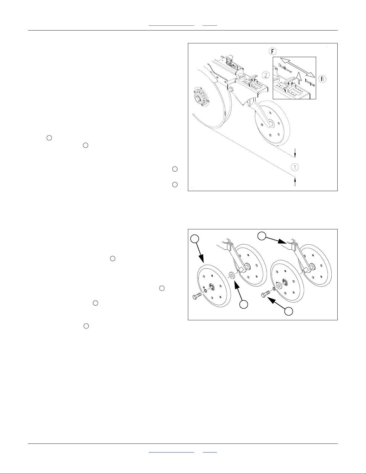
1510HDP, 2010HDP and 2510HDP Table of Contents Index Adjustments
Figure 64
Initial Opener Depth
27124
1
2
F
B
Figure 65
Double-V Press Wheels
23428
1
2
3
4
123
4
Press Wheel Adjustments
Opener Depth (Press Wheel Height)
Seeding depth on 10HDP 3-point drills is set by row unit
depth, which is controlled primarily by press wheel
height. Set frame height (page 18) before making row
unit depth adjustments.
10HD Series press wheel height is a stop adjustment
and not a spring adjustment. It establishes a fixed
relationship between opener depth and the closed-furrow
surface at the press wheel
Refer to Figure 64
Set opener seeding depth by adjusting press-wheel
height . To adjust, first raise openers slightly, then lift
and slide T handles on top of openers. Initially adjust
all press wheels to the same height. Individual rows
running in tire tracks may need to be set deeper.
• For more shallow seeding, slide T handles forward
toward drill.
• For deeper seeding, slide T handles backward
away from drill.
If press wheels are lifting off ground, check front-to-back
level, and increase row unit spring down force.
If press wheels are digging into ground, reduce spring
down force at the row units.
Press Wheel Spacing
Double V Press Wheel Adjustment
Refer to Figure 65
The double-V closing wheels can be moved inward
and outward to alter how they close the seed trench and
press soil over the seed.
To move the wheels in toward the center of the trench,
remove one of the
to the press wheel arm and position it under the head of
the hex head cap screw .
On wider row spacings the closing wheels can be moved
outward by relocating the spacers to the inside, next to
the press wheel arm .
1
in (6.4mm) spacer bushings next
4
Great Plains | 118-245M | 2018-07-18 Table of Contents Index 65
Page 70
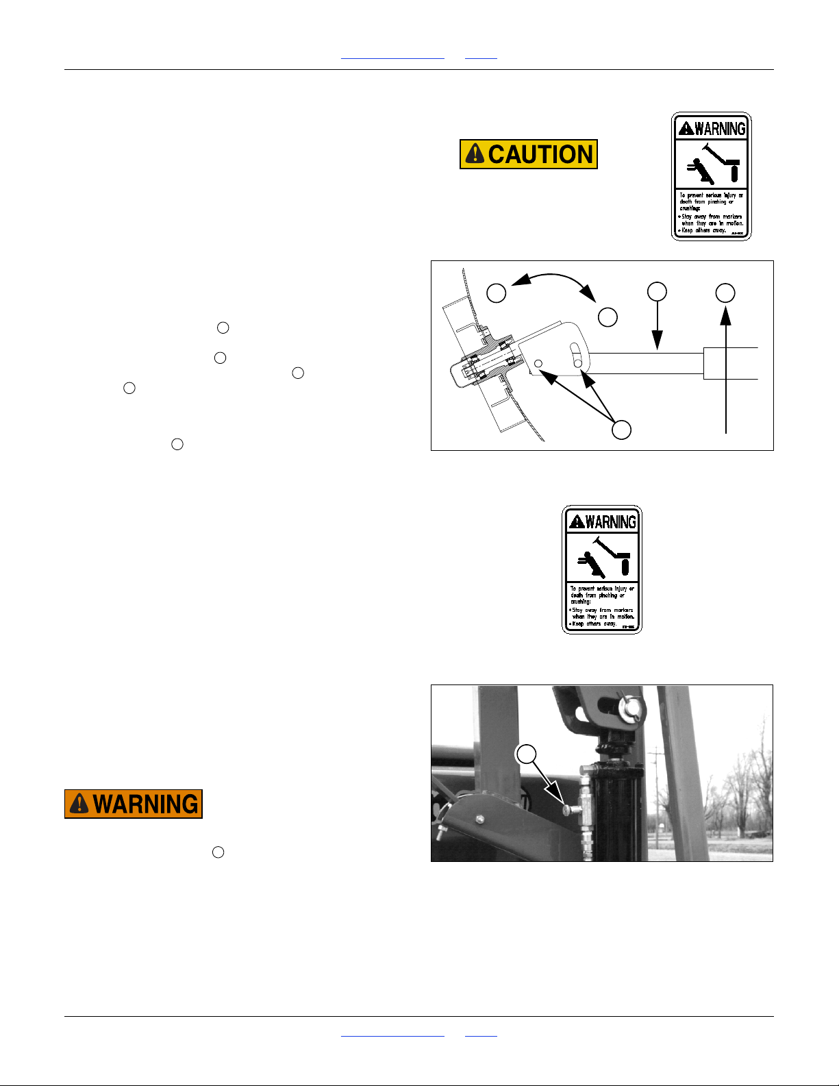
1510HDP, 2010HDP and 2510HDP Table of Contents Index Adjustments
Marker disks may be sharp.
Use caution when making
adjustments in this area.
Figure 66
Marker Disk Angle
11757
T
2
1
N
W
T
2W1N2
Figure 67
Needle valve Adjustment
17620
1
1
Marker Adjustments
See other sections for these marker items:
Marker Setup:
“Marker Extension Setup” on page 25
Marker Maintenance:
“Bleeding Marker Hydraulics” on page 113
“Marker Chain Adjustment” on page 24
“Marker Transport Carrier” on page 114
Marker Disk Angle
Refer to Figure 66
To change angle of cut, and the width of the mark:
1. Loosen
For a wider mark , increase the angle of the
marker with respect to the tube . For a narrower
mark , reduce the angle.
To change direction of cut (throw dirt out vs. in), invert
disk blade on hub, or invert disk assembly on tube.
2. Tighten bolts .
1
-inch bolts holding the disk assembly.
2
Marker Speed
The folding speed of independent markers (on separate
hydraulic circuits) is controlled by needle valves at the
cylinders.
The folding speed of sequenced dual markers is
controlled by an adjustment at the sequence valve.
Excessive folding speed can damage markers and void
the warranty.
Folding Speed with Needle Valves
This applies only to markers plumbed separately (left
and right are each on their own tractor hydraulic circuit).
Refer to Figure 67
A needle valve controls the folding speed. The needle
valve is near the rod end of the marker cylinder. With
tractor idling at a normal operating speed, adjust marker
folding to a safe speed.
Do not adjust needle valve while marker is in motion.
Turn adjustment knob clockwise to reduce folding
speed or counterclockwise to increase folding speed.
Folding Speed with Sequence Valve
Great Plains | 118-245M | 2018-07-18 Table of Contents Index 66
Page 71
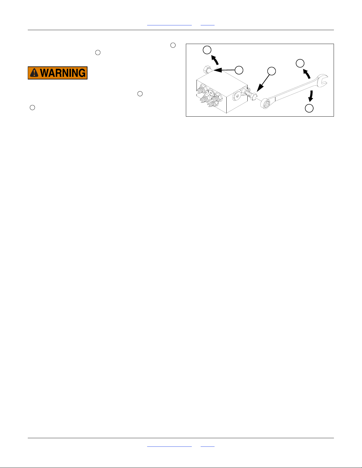
1510HDP, 2010HDP and 2510HDP Table of Contents Index Adjustments
1
2
F
S
S
Figure 68
Sequence Valve Adjustment
14048
12S
F
There is one adjustment screw for unfolding speed
and one for folding speed . You can identify adjustment
screws by markings stamped in valve body.
Do not adjust sequence valve while marker is in motion.
Turn adjustment screws clockwise ( : slower) to
decrease [un]folding speed and counterclockwise
( : faster) to increase [un]folding speed.
With tractor idling at a normal operating speed, adjust
marker folding to a safe speed. Excessive [un]folding
speed could damage markers and void the warranty.
After adjusting the folding speed, tighten jam nuts on hex
adjustment screws to hold settings.
Great Plains | 118-245M | 2018-07-18 Table of Contents Index 67
Page 72
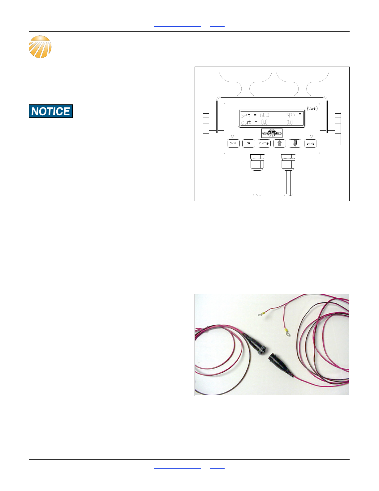
1510HDP, 2010HDP and 2510HDP Table of Contents Index Hydraulic Drive Operation
22715
Figure 69
Controller Electrical Connection
22714
Hydraulic Drive Operation
Drive Operational Requirements
Hydraulic System:
Closed Center, pressure compensated or load sensed
systems only
Drive will not operate on Open-Center hydraulic systems
Minimum Hydraulic Pressure 2250 psi
Maximum Hydraulic Pressure 3000 psi
Maximum Required Flow 8.5 gpm
Electrical System:
Voltage 12 volt DC
Current 4 amperes
Tractor Hookup
Hydraulics:
1. Connect pressure hose (P) to retraction outlet
2. Connect motor return hose (T) to motor return port (if
available) or to extension outlet.
3. Set flow rate at maximum required flow of 13 gpm.
4. If tractor is equipped with electro-hydraulic valves,
set timer to “constant” flow.
Electrical:
Refer to Figure 69
Power must be connected directly to the battery. Make
sure that eyelets are properly connected (red to positive,
black to negative). Connect female socket to power port
adapter.
Great Plains | 118-245M | 2018-07-18 Table of Contents Index 68
Page 73
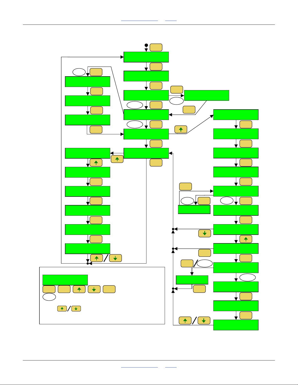
1510HDP, 2010HDP and 2510HDP Table of Contents Index Hydraulic Drive Operation
23251
set= * spd=
out= ______ _._
CALIBRATION
NUMBER *
recipe format
*
ma nual/pres et
*
PRESS UP KEY TO
CALIBRATE RATE
PRESS UP KEY TO
CALIBRATE SPEED
ON / VR
FUNCTION
FUNCTION
FUNCTION
FUNCTION
FUNCTION
UP:KEEP NEW
DN:KEEP OLD
PRESS ENGAGE
T 1ST FLAG
__ft ENGAGE AT
2ND FLAG
DISTANCE ERROR
___%
UP:CALCULATE NEW
DN:KEEP CURRENT
CAL SETTINGS
*
FUNCTION
ENGAGE
ENGAGE
FUNCTION
VERIS V1
selected
RAWSON
selected
FUNCTION
RAWSON NOMINAL
*
PRESET 1
*
PRESET 2
*
PRESET 3
*
MANUAL
selected
FUNCTION
PRESET
selected
FUNCTION
FUNCTION
FUNCTION
FUNCTION
FUNCTION
CAL SETTINGS
*
CAL SETTINGS
WIDTH *
CAL SETTINGS
# ROWS *
CAL SETTINGS
SPEED *
ENTER TARGET
MOUNT *
TIME TO RUN FOR
CAL ___s
CLEAR DRIVE AREA
UP:CLEAR DN:EXIT
ENGAGE:RUN DRIVE
FUNCT:EXIT
FUNCTION
FUNCTION
FUNCTION
FUNCTION
FUNCTION
ENGAGE
__s ou t= ______
ENGAGE TO STOP
calibration
successful
ENTER AMOUNT
COLLECTED *
NEW CAL #: ____
OLD CAL #: ____
FUNCTION
FUNCTION
FUNCTION
**
FUNCTION:EXIT
calibration
error
ENGAGE
FUNCTION
FUNCTION
KEY
s et = * s pd=
o u t = ______ _. _
-
cab console LCD screen
ON / VR
FUNCTION ENGAGE
-
Keys on cab console
-
Condition for progressing to next screen
*Adjust number up/down or toggle between selections using
the keys.
** Refer to the troubleshooting section of the manual for a
description of error messages.
valid
time
**
FUNCTION
invalid
time
FUNCTION
UP:CALIBRATE
DN:RESTORE
RATE CALIBRATION
SPEED CALIBRATION
PRESET RATES
VARIABLE RATE
Controller Menu
A
_
_
Great Plains | 118-245M | 2018-07-18 Table of Contents Index 69
A
_
Page 74
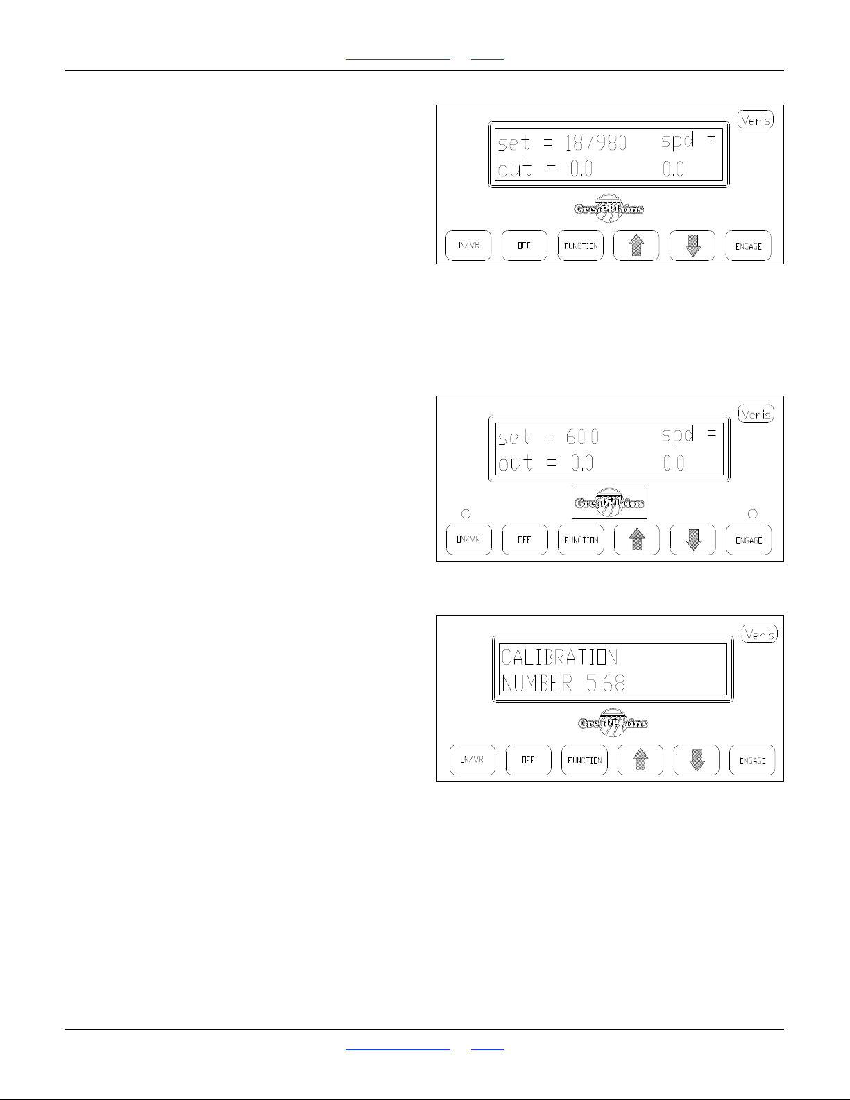
1510HDP, 2010HDP and 2510HDP Table of Contents Index Hydraulic Drive Operation
Figure 70
Controller Key Functions
22710
Figure 71
Initiate Calibration
22715
Figure 72
Calibration Number Prompt
22716
Console Functions
Refer to Figure 70
The use of each key is as follows:
• On/VR key-turns drive system on. Press twice for VR
mode. Note: Engage key must also be pressed to
start drive operation.
• Off key: used to shut off Console.
• Function key: used in calibration mode and to
program Console for VR recipes.
• Up/down arrow keys: used to change rates manually,
to set calibration numbers, and VR controller options.
• Engage key: press to start drive.
Drive will not run unless light above key is illuminated.
Figure 70 shows Main Operating Screen in manual
mode.
Calibration
Refer to Figure 71
1. Turn on Controller Console by pressing On/VR key.
Green light above On/VR key will illuminate when
power is on. Adjust desired planting rate by using the
Up/Down arrow keys to change the Set rate.
2. Set the desired Rate by using the Up/Down arrow
keys.
Refer to Figure 72
3. Press Function key until Calibration Number window
appears.
4. Select drive calibration number based on row
spacing and metering wheel, from chart. See
“Hydraulic Drive Calibration” on page 79.
5. Use Up/Down arrow keys to set Calibration number.
Great Plains | 118-245M | 2018-07-18 Table of Contents Index 70
Page 75
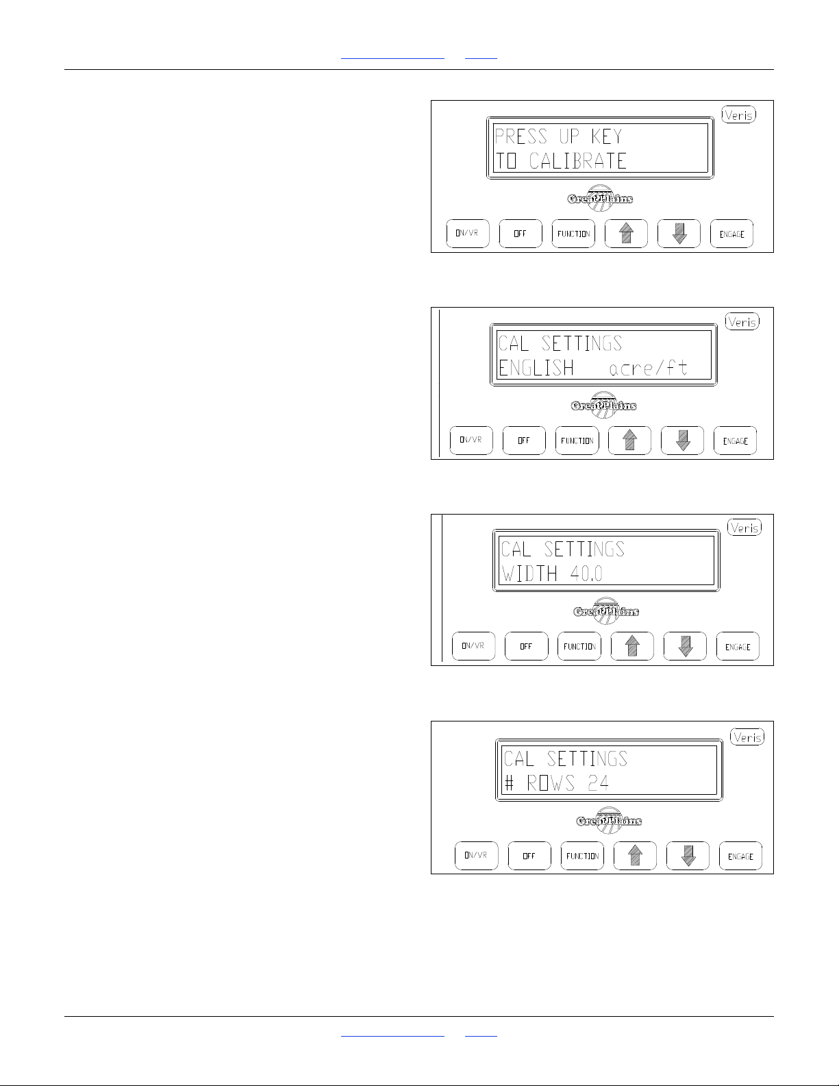
1510HDP, 2010HDP and 2510HDP Table of Contents Index Hydraulic Drive Operation
Figure 73
Press Up Key to Calibrate
22717
Figure 74
Measurement Mode
22718
Figure 75
Cal. Mode Drill Width
22779
Figure 76
Cal. Mode Row Count
22720
Refer to Figure 73
6. Press Function key until the Calibration window
appears as shown.
7. Press up arrow key to enter calibration mode.
Refer to Figure 74
8. This is the first window that appears in Calibration
mode. Press Function key to accept, or Up key to
change to metric settings.
Refer to Figure 75
9. Enter drill width here using Up/Down arrow keys.
Press Function key to advance to next window.
Refer to Figure 76
10. Enter number of rows here using Up/Down arrow
keys. Press Function key to advance to next window.
Great Plains | 118-245M | 2018-07-18 Table of Contents Index 71
Page 76
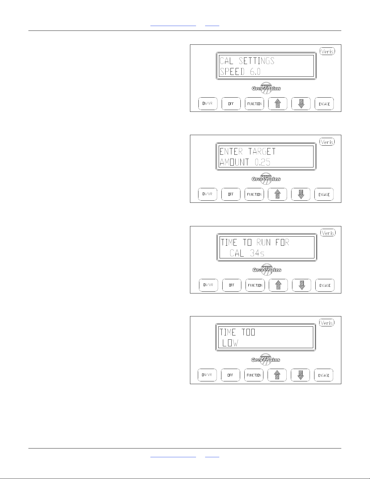
1510HDP, 2010HDP and 2510HDP Table of Contents Index Hydraulic Drive Operation
Figure 77
Cal. Mode Speed
22721
Figure 78
Cal. Mode Seed Target
22722
Figure 79
Cal. Mode Time Window
22723
Figure 80
Cal. Mode Time Limit Error
22782
Refer to Figure 77
11. Enter your planned planting speed using Up/Down
arrow keys. Calibration mode will not accept a speed
higher than 10 mph. Press Function key to advance
to next window.
Refer to Figure 78
12. Enter the amount of seed you want to measure. For
volumetric metering, this should be at least
1
4
of a
pound. For singulated metering, at least 100 seeds
should be selected. Press Function key to advance
to next window.
Refer to Figure 79
13. The cab console informs you of the length of time
that the drive will be operating, in order to meter the
amount of seed you have requested, at the
calibration number, drill width, and number of rows
you have selected. Press Function key to advance to
next window.
Refer to Figure 80
14. If the screen reads TIME TOO LOW, or TIME TOO
HIGH, you will need to change the amount of seed
that you will count or measure. For calibration
accuracy, the Controller firmware will not allow you to
calibrate at settings that would result in the drive
rotating for less than 4 seconds, or more that 255
seconds. Press Function key to advance to next
window.
Great Plains | 118-245M | 2018-07-18 Table of Contents Index 72
Page 77
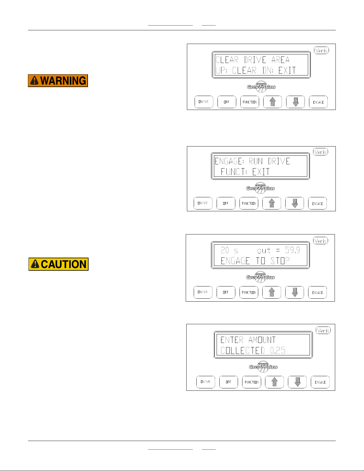
1510HDP, 2010HDP and 2510HDP Table of Contents Index Hydraulic Drive Operation
Figure 81
Cal. Mode Clear Area
22724
Figure 82
Cal. Mode Initiate Motion
22726
Figure 83
Cal. Mode Prompt In Motion
22727
Figure 84
Cal. Mode Normal Completion
22728
Refer to Figure 81
15. The drive is about to operate, meaning there is a
danger of entanglement if anyone is in the drive
area.
Be sure to verify that no one is near the drive area before
advancing to the next step.
Refer to Figure 81
16. Only after you have verified the drive area is clear,
press the up arrow key to initiate calibration mode. If
drive area isn’t clear, press Down arrow key to exit
calibration mode.
Refer to Figure 82
17. Continuing to verify that the drive area is clear, press
the Engage key to start drive rotation. Pressing
Function key will exit calibration mode.
Refer to Figure 83
18. While the drive is rotating, the display window shows
the time remaining and the “Out” rate.
CONTINUE TO MONITOR DRIVE AREA DURING DRIVE
ROTATION. PRESS THE ENGAGE KEY (OR OFF KEY) TO
STOP DRIVE DURING CALIBRATION
Refer to Figure 84
19. After Calibration meter rotation has ended, this
screen will appear.
Great Plains | 118-245M | 2018-07-18 Table of Contents Index 73
Page 78
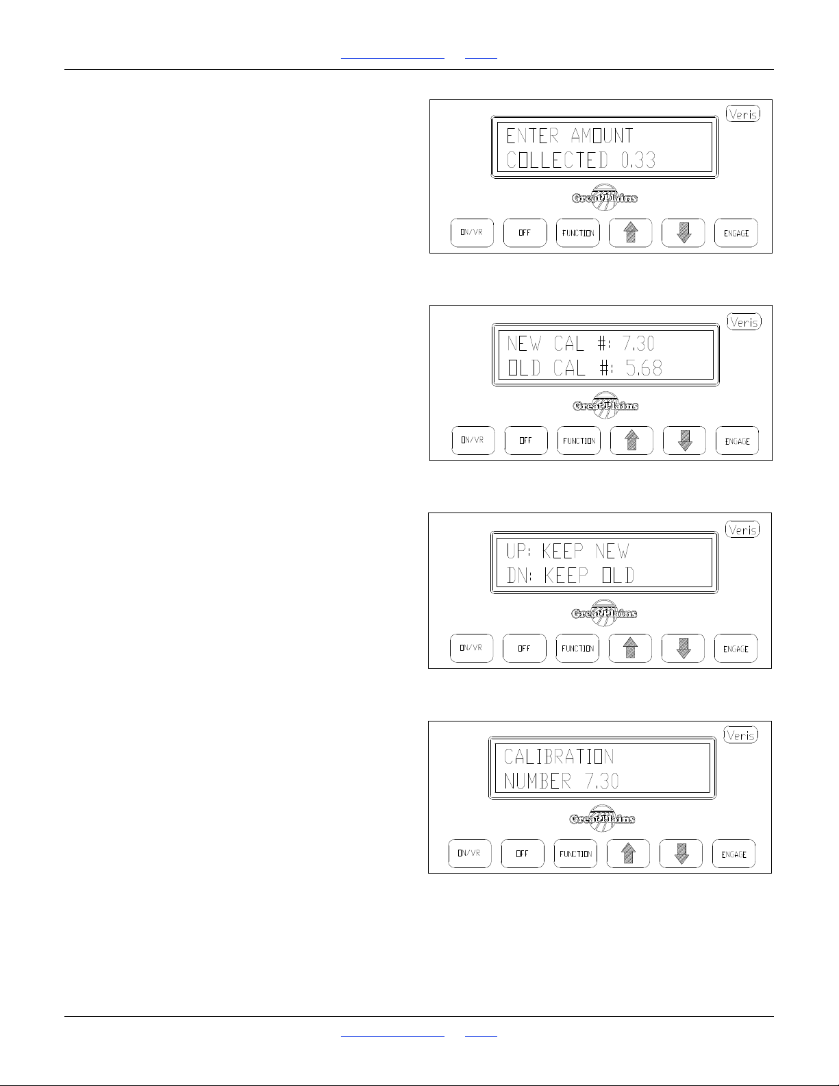
1510HDP, 2010HDP and 2510HDP Table of Contents Index Hydraulic Drive Operation
Figure 85
Cal. Mode Enter Seed Count
22729
Figure 86
Calibration Number
22730
Figure 87
Calibration Number
22731
Figure 88
Calibration Number Accepted
22732
Refer to Figure 85
20. Enter the actual amount metered using the Up/Down
arrow keys. Press Function key to advance to next
window.
Refer to Figure 86
21. A New calibration number is suggested, along with
the old calibration number.
Refer to Figure 87
22. Press Function key to advance to window shown.
23. If you wish to keep the old number, perhaps to re-run
the calibration procedure, press the Down arrow key.
If you want to accept the New calibration number,
press the Up arrow key.
Refer to Figure 88
24. Console window now displays the calibration number
you have selected.
Great Plains | 118-245M | 2018-07-18 Table of Contents Index 74
Page 79
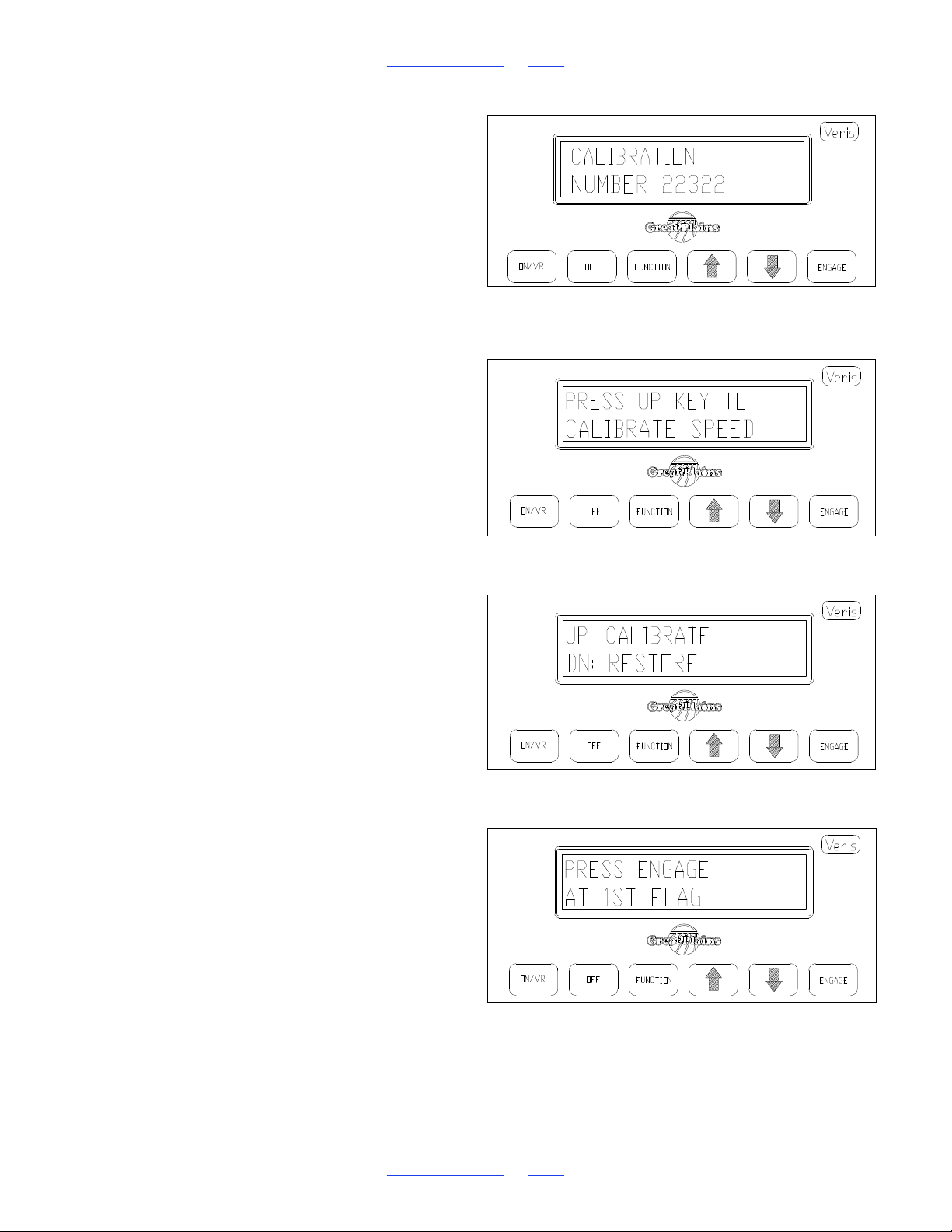
1510HDP, 2010HDP and 2510HDP Table of Contents Index Hydraulic Drive Operation
Figure 89
Cal. Mode Recycle
22733
Figure 90
Speed Cal. Mode
22788
Figure 91
Initiate Speed Calibration
22789
Figure 92
At First Flag
22790
Refer to Figure 89
25. This returns you back to the beginning of Calibration
mode as shown. To re-run the Calibration procedure,
follow the steps outlined above. It is suggested that
you perform the calibration mode at least twice, and
additional replications may be needed if Target and
Actual amounts vary significantly.
Speed Calibration
In order to fine-tune the default speed calculation or to
convert to radar speed signal, the controller may be
calibrated as follows:
1. Set two flags 400ft apart (100 meters if in metric
mode).
Refer to Figure 90
2. To calibrate the Controller for speed, press the
Function key until the screen appears, as shown.
Refer to Figure 91
3. Press up to initiate new speed calibration routine;
press down to restore factory default settings.
Refer to Figure 92
4. Begin driving at a normal field speed; when the
tractor passes the first flag, press ENGAGE.
Great Plains | 118-245M | 2018-07-18 Table of Contents Index 75
Page 80
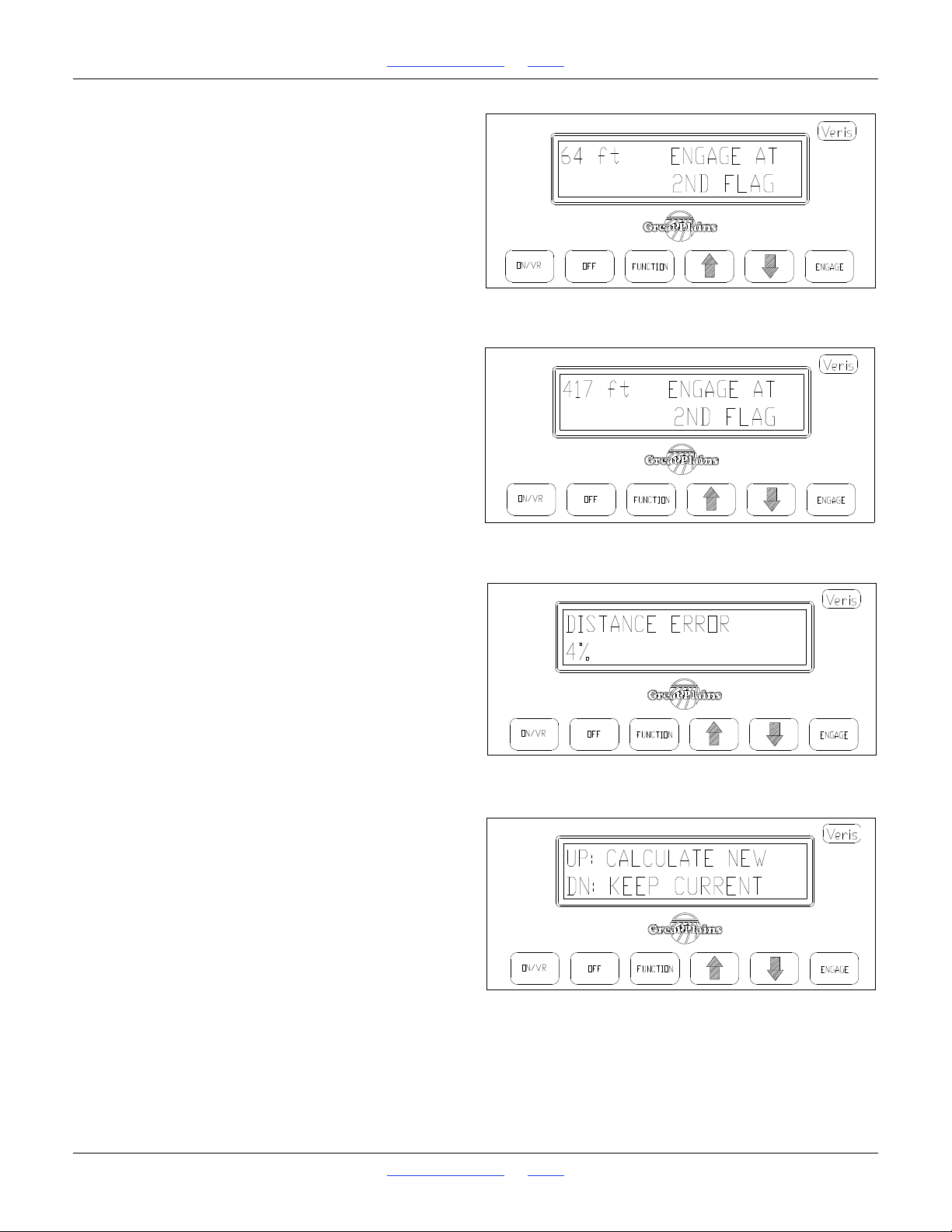
1510HDP, 2010HDP and 2510HDP Table of Contents Index Hydraulic Drive Operation
Figure 93
Between Flags
22791
Figure 94
At Second Flag
22792
Figure 95
Distance Variance
22793
Figure 96
Save/Ignore Result
22794
Refer to Figure 93
5. While between flags, the display shows the distance
traveled.
Refer to Figure 94
6. When the tractor passes the second flag, press
engage again.
Refer to Figure 95
7. The display will show the error or difference between
the traveled distance and the distance calculated by
the Controller.
Refer to Figure 96
8. If this is the first time the unit has been calibrated,
this error can be large. Accept the new speed
calibration and re-run the course. Re-calibrate until
the error is within 5%. The cab console will give you
the option each time you calibrate of accepting the
new settings, or keeping the previous settings.
Great Plains | 118-245M | 2018-07-18 Table of Contents Index 76
Page 81
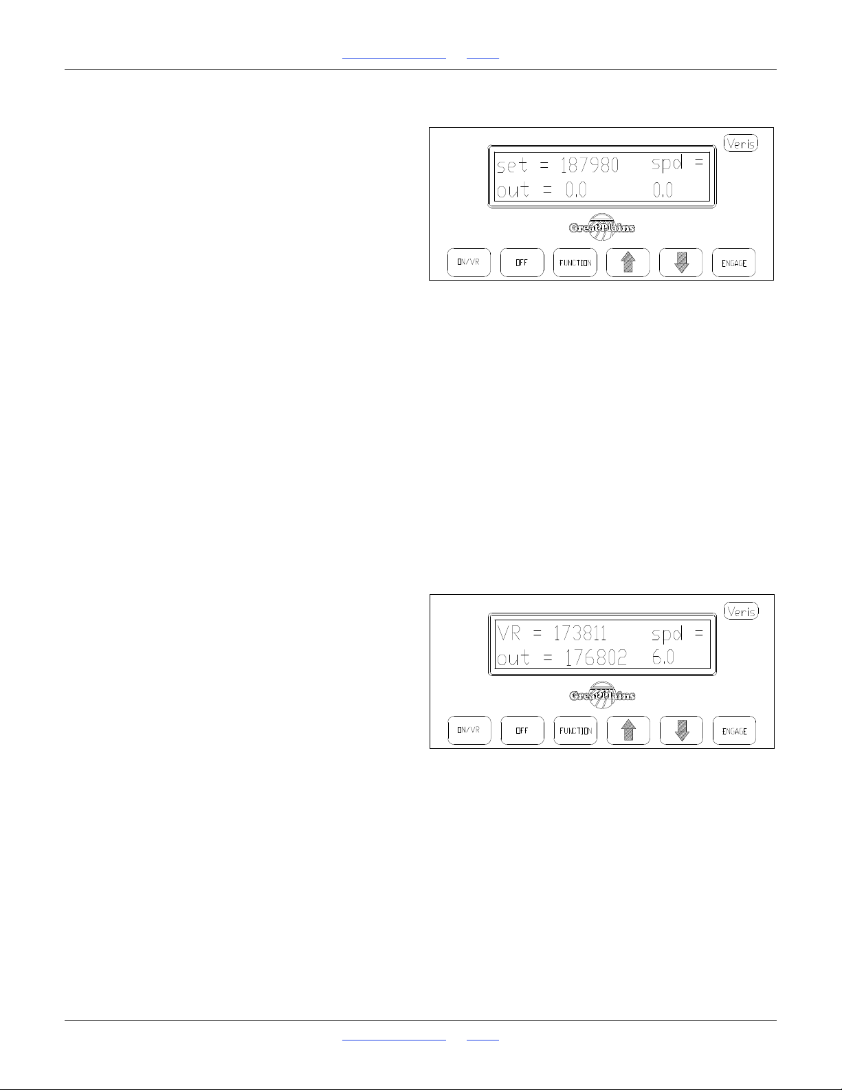
1510HDP, 2010HDP and 2510HDP Table of Contents Index Hydraulic Drive Operation
Figure 97
Enter VR Mode
22710
Figure 98
VR Mode
22734
Operations
Before going to the field
Once calibration procedure above has been followed,
Console will store the calibration and rate information
until new information has been entered.
Refer to Figure 97
1. Turn on Console by pressing On/VR key. Pressing
the On/VR key twice will put the unit in VR (Variable
Rate) mode. Leave Console in manual mode.
For units with P/N 21567 skip step 2.
2. To double-check calibration before planting, follow
same procedure as for mechanical ground drives as
outlined in Great Plains Precision Seeding System
Operator’s Manual, with these differences:
Volumetric: use extreme caution when performing
this calibration to prevent injury due to drive
entanglement. Also, turn drive gauge wheel with a
consistent speed of at least 30 rpm for maximum
calibration accuracy.
Singulated: Rather than calibrating from a standing
start, measure the distance as listed in the GP
manual, and set two flags. Start driving far enough in
advance of the first flag that your unit is operating at
field speed (min. 3 mph) during the calibration
distance.
In Field
Refer to Figure 98
1. Turn on Controller Console by pressing the On/VR
key. Green light above On/VR key will illuminate
when power is on. Pressing the On/VR key twice will
put the unit in VR mode. VR will appear on the
screen along with the Rate that is being sent from
the computer. Press On/VR key again to toggle back
to manual mode. (Mode and rate changes take effect
with the release of the key.)
2. To change rates manually whether in manual or in
VR mode, simply touch the Up/Down arrow keys.
This will change the Controller to the rate you select
manually. To return to VR, simply touch the On/VR
key to toggle back to VR mode.
3. Engage the hydraulic flow by pushing FORWARD on
the tractor remote hydraulic lever. The remote lever
must be LOCKED OPEN in this position to provide
constant flow to the drive motor.
John Deere tractors with Sound-Gard® body: Use
lever lock clip to lock lever forward. See your tractor
dealer for lock purchase and installation.
John Deere 7000 Series tractors: Rotate valve
detent selector to motor position to lock lever in
forward position.
John Deere 8000 Series tractors: Set timer to
continuous. Push lever forward until detent clicks.
Case-IH Magnum tractors: Lock lever forward in
detent position. You may need to turn up detent
pressure to its maximum setting. Do not tie hydraulic
lever past detent position with a strap. See your
tractor dealer for details.
Other tractors: Lock lever forward in detent position.
You may need to turn detent pressure to maximum
Great Plains | 118-245M | 2018-07-18 Table of Contents Index 77
Page 82

1510HDP, 2010HDP and 2510HDP Table of Contents Index Hydraulic Drive Operation
or use a mechanical detent holder to hold lever
forward. See your tractor dealer for proper means of
providing constant flow.
4. Press Engage key to activate drive. Green light
above Engage key will illuminate.
If you do not move within 10 seconds, the automatic
disengagement feature will disengage the drive. To
begin planting again, you must press the Engage
key.
5. The Console display shows two numbers while
operating: “Set” rate is the rate you tell the system to
plant, and the “Out” rate is the calculated rate based
on the actual rotations of the drive. The “Out”
reading is monitoring the drive system; it isn’t
monitoring population. It verifies that the drive
system is functioning properly.
The “Out” readings will normally fluctuate within 5%
of the “Set” rates. This fluctuation is evidence of the
drive system compensating for minor fluctuations in
ground speed.
6. If “Out” rate varies from the “Set” rate by more than
20%, an audible alarm will sound.
7. If Controller is powered directly from the battery or
via unswitched power port, make sure to power
Console off when tractor is shut down, in order to
prevent tractor battery drain.
When calibrating, make sure that you choose a calibration speed that is representative of your average planting
speed.
Great Plains | 118-245M | 2018-07-18 Table of Contents Index 78
Page 83
1510HDP, 2010HDP and 2510HDP Table of Contents Index Hydraulic Drive Operation
1510HDP Hydraulic Drive Calibration
Crop Notes
Corn 20in Single 6 Finger 13500 37000 750 1, 3
Corn 20in Single 12 Finger 17500 47700 1501 1, 2
Corn 20in Single 28 Cell 14000 38000 1751 1, 3
Corn 20in Single 42 Cell 21000 57000 2627 1, 3
Corn 30in Single 6 Finger 9000 25000 500 1, 3
Corn 30in Single 12 Finger 17500 47700 1000 1, 2
Corn 30in Single 28 Cell 14000 38000 1167 1, 3
Corn 30in Single 42 Cell 21000 57000 1751 1, 3
Corn 30in Twin 6 Finger 17500 47500 1000 1, 2
Corn 30in Twin 12 Finger 36000 98 000 2001 1, 2
Corn 30in Twin 28 Cell 14000 38000 2334 1, 2
Corn 30in Twin 42 Cell 21000 57000 3501 1, 2
Cotton 7.5in Single 120 Cell 60000 325500 20008 1, 2
Cotton 10in Single 120 Cell 60000 325500 15006 1, 2
Cotton 10in TRS All 120 Cell 60000 325500 15006 1, 2
Cotton 15in Single 120 Cell 30000 325500 10004 1, 2
Cotton 20in Single 120 Cell 30000 81400 7504 1, 2
Cotton 30in Single 120 Cell 30000 81400 5002 1, 3
Cotton 30in Twin 120 Cell 30000 325500 10004 1, 2
Milo 7.5in Single 51 Cell 25500 69200 8504 1, 2
Milo 7.5in Single 102 Cell 51000 138300 17007 1, 2
Milo 7.5in Single 135 Cell 67500 183000 22509 1, 2
Milo 10in Single 51 Cell 25500 69200 6378 1, 2
Milo 10in Single 102 Cell 51000 138300 12755 1, 2
Milo 10in Single 135 Cell 67500 183000 16882 1, 2
Milo 10in TRS All 51 Cell 25500 69200 6378 1, 2
Milo 10in TRS All 102 Cell 51000 138300 12755 1, 2
Milo 10in TRS All 135 Cell 67500 183000 16882 1, 2
Milo 15in Single 51 Cell 25500 69200 4252 1, 2
Milo 15in Single 102 Cell 51000 138300 8504 1, 2
Milo 15in Single 102 Cell 25500 69200 8504 1, 2
Milo 15in Single 1
35 Cell 67500 183000 11255 1, 2
Milo 15in Single 135 Cell 33700 91500 11255 1, 2
Milo 15in Single 270 Cell 67500 183000 22510 1, 2
Singulated: 1 of 2
Row
Spacing
Meter
Type
Minimum
Rate
Maximum
Rate
Cal.
Number
Hydraulic Drive Calibration
1510HDP Page 1 of 4
1. Cal number should be accurate, but Great Plains
strongly suggests the use of the Calibration Routine
to fine tune the actual seeding rate at the desired
planting speed
2. Refer to seed chart to determine optimum planting
speed for your nominal rate.
3. Extremely high rates on wide row spacing may
require lower ground speed -- refer to seed charts for
mph/kph limitation.
Great Plains | 118-245M | 2018-07-18 Table of Contents Index 79
Page 84
1510HDP, 2010HDP and 2510HDP Table of Contents Index Hydraulic Drive Operation
1510HDP Hydraulic Drive Calibration
Crop Notes
Milo 20in Single 102 Cell 25500 69200 6379 1, 2
Milo 20in Single 135 Cell 33700 91500 8442 1, 2
Milo 20in Single 270 Cell 67500 183000 16885 1, 2
Milo 30in Single 102 Cell 25500 69200 4252 1, 3
Milo 30in Single 135 Cell 33700 91500 5627 1, 3
Milo 30in Single 270 Cell 67500 183000 11255 1, 3
Milo 30in Twin 51 Cell 25500 69200 4252 1, 2
Milo 30in Twin 102 Cell 25500 69200 8504 1, 2
Milo 30in Twin 102 Cell 51000 138300 8504 1, 2
Milo 30in Twin 135 Cell 67500 183000 11255 1, 2
Milo 30in Twin 135 Cell 33700 91500 11255 1, 2
Milo 30in Twin 270 Cell 67500 183000 22509 1, 2
Soybeans 7.5in Single 100 Cell 100000 271000 16674 1, 2
Soybeans 7.5in S
ingle 110 Cell 110000 298000 18341 1, 2
Soybeans 10in Single 100 Cell 100000 271000 12505 1, 2
Soybeans 10in Single 110 Cell 110000 298000 13756 1, 2
Soybeans 10in TRS All 100 Cell 100000 271000 12505 1, 2
Soybeans 10in TRS All 110 Cell 110000 298000 13756 1, 2
Soybeans 15in Single 100 Cell 100000 271000 8337 1, 2
Soybeans 15in Single 110 Cell 110000 298000 9171 1, 2
Soybeans 20in Single 100 Cell 100000 271000 6254 1, 3
Soybeans 20in Single 110 Cell 110000 298000 68
79 1, 3
Soybeans30in Single 100 Cell 100000 271000 4168 1, 3
Soybeans30in Single 110 Cell 110000 298000 4585 1, 3
Soybeans30in Twin 100 Cell 100000 271000 8337 1, 2
Soybeans30in Twin 110 Cell 110000 298000 9171 1, 2
Singulated: 2 of 2
Row
Spacing
Meter
Type
Minimum
Rate
Maximum
Rate
Cal.
Number
1510HDP Page 2 of 4
1. Cal number should be accurate, but Great Plains
strongly suggests the use of the Calibration Routine
to fine tune the actual seeding rate at the desired
planting speed
2. Refer to seed chart to determine optimum planting
speed for your nominal rate.
3. Extremely high rates on wide row spacing may
require lower ground speed -- refer to seed charts for
mph/kph limitation.
Great Plains | 118-245M | 2018-07-18 Table of Contents Index 80
Page 85
1510HDP, 2010HDP and 2510HDP Table of Contents Index Hydraulic Drive Operation
1510HDP Hydraulic Drive Calibration Volumetric: 1 of 2
Crop Notes
Barley 7.5in Single Wheat Narrow 403-118D 24 66 4.00 4
Barley 10in Single Wheat Narrow 403-118D 24 66 3.00 4
Barley 10in TRS All Wheat Narrow 403-118D 24 66 3.00 4
Barley 15in Single Wheat Narrow 403-118D 24 66 2.00 4
Barley 30in Twin Wheat Narrow 403-118D 24 66 2.00 4
Barley 7.5in Single Wheat Wide 403-119D 53 144 8.77 4
Barley 10in Single Wheat Wide 403-119D 53 144 6.58 4
Barley 10in TR
S All Wheat Wide 403-119D 53 144 6.58 4
Barley 15in Single Wheat Wide 403-119D 53 144 4.39 4
Barley 30in Twin Wheat Wide 403-119D 53 144 4.39 4
Barley 7.5in Single V 3 403-120D 66 180 10.92 4
Barley 10in Single V 3 403-120D 66 180 8.19 4
Barley 10in TRS All V 3 403-120D 66 180 8.19 4
Barley 15in Single V 3 403-120D 66 180 5.46 4
Barley 30in Twin V 3 403-120D 66 180 5.46 4
Oats 7.5in S
ingle Wheat Narrow 403-118D 16 44 2.67 4
Oats 10in Single Wheat Narrow 403-118D 16 44 2.00 4
Oats 10in TRS All Wheat Narrow 403-118D 16 44 2.00 4
Oats 15in Single Wheat Narrow 403-118D 16 44 1.33 4
Oats30in Twin Wheat Narrow 403-118D 16 44 1.33 4
Oats 7.5in Single Wheat Wide 403-119D 39 106 6.44 4
Oats 10in Single Wheat Wide 403-119D 39 106 4.83 4
Oa
ts 10in TRS All Wheat Wide 403-119D 39 106 4.83 4
Oats 15in Single Wheat Wide 403-119D 39 106 3.22 4
Oats30in Twin Wheat Wide 403-119D 39 106 3.22 4
Oats 7.5in Single V 3 403-120D 53 144 8.75 4
Oats 10in Single V 3 403-120D 53 144 6.57 4
Oats 10in TRS All V 3 403-120D 53 144 6.57 4
Oats 15in Single V 3 403-120D 53 144 4.38 4
Oats3
0in Twin V 3 403-120D 53 144 4.38 4
Rice 7.5in Single Rice Low Rate 403-426D 25 36 2.28 4, 5
Rice 10in Single Rice Low Rate 403-426D 25 36 1.71 4, 5
Rice 10in TRS All Rice Low Rate 403-426D 25 36 1.71 4, 5
Rice 15in Single Rice Low Rate 403-426D 25 36 1.14 4, 5
Rice 30in Twin Rice Low Rate 403-426D 25 36 1.14 4, 5
Row
Spacing
Wheel
Type
Wheel
Part No.
Minimum
Rate
Maximum
Rate
Cal.
Number
1510HDP Page 3 of 4
4. Field speed may affect actual rate with volumetric
meters.
5. Requires use of 817-529C Flow Gate.
Great Plains | 118-245M | 2018-07-18 Table of Contents Index 81
Page 86
1510HDP, 2010HDP and 2510HDP Table of Contents Index Hydraulic Drive Operation
1510HDP Hydraulic Drive Calibration Volumetric: 2 of 2
Crop Notes
Rice 7.5in Single Rice Med Rate 403-143D 45 71 4.34 4, 5
Rice 10in Single Rice Med Rate 403-143D 45 71 3.25 4, 5
Rice 10in TRS All Rice Med Rate 403-143D 45 71 3.25 4, 5
Rice 15in Single Rice Med Rate 403-143D 45 71 2.17 4, 5
Rice 30in Twin Rice Med Rate 403-143D 45 71 2.17 4, 5
Rice 7.5in Single Rice High Rate 403-121D 67 121 7.34 4, 5
Rice 10in Single Rice High Rate 403-121D 67 121 5.50 4, 5
Rice 10in TRS All Rice High Rate 403-121D 67 121 5.50 4, 5
Rice 15in Single Rice High Rate 403-121D 67 121 3.67 4, 5
Rice 30in Twin Rice High Rate 403-121D 67 121 3.67 4, 5
Rye 7.5in Single Wheat Na
rrow 403-118D28 77 4.67 4
Rye 10in Single Wheat Narrow 403-118D28 77 3.50 4
Rye 10in TRS All Wheat Narrow 403-118D28 77 3.50 4
Rye 15in Single Wheat Narrow 403-118D28 77 2.33 4
Rye 30in Twin Wheat Narrow 403-118D28 77 2.33 4
Rye 7.5in Single Wheat Wide 403-119D 63 170 10.34 4
Rye 10in Single Wheat Wide 403-119D 63 170 7.75 4
Rye 10in TRS All Wheat Wide 403-119D 63 170 7.75 4
Rye 15in Single Wheat Wide 40
3-119D 63 170 5.17 4
Rye 30in Twin Wheat Wide 403-119D 63 170 5.17 4
Wheat Hard Red 7.5in Single Wheat Narrow 403-118 D 34 93 5.67 4
Wheat Hard Red 10in Single Wheat Narrow 403-118D 34 93 4.25 4
Wheat Hard Red 10in TRS All Wheat Narrow 403-118D 34 93 4.25 4
Wheat Hard Red 15in Single Wheat Narrow 403-118D 34 93 2.83 4
Wheat Hard Red 30in Twin Wheat Na
rrow 403-118D 34 93 2.83 4
Wheat Hard Red 7.5in Single Wheat Wide 403-119D 79 214 13.01 4
Wheat Hard Red 10in Single Wheat Wide 403-119D 79 214 9.75 4
Wheat Hard Red 10in TRS All Wheat Wide 403-119D 79 214 9.75 4
Wheat Hard Red 15in Single Wheat Wide 403-119D 79 214 6.50 4
Wheat Hard Red 30in Twin Wheat Wide 403-119D 79 214 6.50 4
Wheat Soft Red 7.5in Single V 3 403-120D 92 249 15.11 4
Wheat Soft Red 10in Single V 3 403-120D 92 249 11.33 4
Wheat Soft Red 10in TRS All V 3 40
3-120D 92 249 11.33 4
Wheat Soft Red 15in Single V 3 403-120D 92 249 7.55 4
Wheat Soft Red 30in Twin V 3 403-120D 92 249 7.55 4
Wheat Soft Red 7.5in Single Wheat Wide 403-119D 69 187 11.34 4
Wheat Soft Red 10in Single Wheat Wide 403-119D 69 187 8.50 4
Wheat Soft Red 10in TRS All Wheat Wide 403-119D 69 187 8.50 4
Wheat Soft Red 15in Single Wheat Wide 403-119D 69 187 5.67 4
Wheat Soft Red 30in Twin Wheat Wide 403-119D 69 187 5.67 4
Row
Spacing
Wheel
Type
Wheel
Part No.
Minimum
Rate
Maximum
Rate
Cal.
Number
1510HDP Page 4 of 4
6. Field speed may affect actual rate with volumetric
meters.
7. Requires use of 817-529C Flow Gate.
Great Plains | 118-245M | 2018-07-18 Table of Contents Index 82
Page 87
1510HDP, 2010HDP and 2510HDP Table of Contents Index Hydraulic Drive Operation
2010 & 2510HDP Hydraulic Drive Calibration
Crop Notes
Corn 20in Single 6 Finger 13200 35800 750
1, 3
Corn 20in Single 12 Finger 17500 47700 1501
1, 2
Corn 20in Single 28 Cell 13700 38000 1751
1
Corn 20in Single 42 Cell 20500 55700 2626
1
Corn 30in Twin 42 Cell 20500 55700 3501
1
Corn 30in Single 6 Finger 8800 23900 500
1, 3
Corn 30in Single 12 Finger 17600 47700 1000
1, 2
Corn 30in Single 28 Cell 13700 38000 1167
1, 3
Corn 30in Single 42 Cell 20500 55700 1751
1, 3
Corn 30in Twin 6 Finger 17600 47700 1000
1, 2
Corn 30in Twin 12 Finger 30600 63600 2001
1, 2
Corn 30in Twin 28 Cell 13700 38000 2334
1
Cotton 7.5in S
ingle 120 Cell 58500 318000 20008
1
Cotton 10in Single 120 Cell 58500 318000 15006
1
Cotton 10in TRS All 120 Cell 58500 318000 15006
1
Cotton 15in Single 120 Cell 58500 318000 10004
1
Cotton 20in Single 120 Cell 58500 318000 7503
1
Cotton 30in Single 120 Cell 29000 79500 5002
1, 3
Cotton 30in Twin 120 Cell 58500 318000 10004
1
Milo 7.5in Single 51 Cell 24900 67500 8504
1
Milo 7.5in Single 102 Cell 49800 135000 17007
1
Milo 7.5in Single 135 Cell 65900 178900 22509
1
Milo 10in Single 51 Cell 24900 67500 6378
1
Milo 10in S
ingle 102 Cell 49800 135000 12755
1
Milo 10in Single 135 Cell 65900 178900 16882
1
Milo 10in TRS All 51 Cell 24900 67500 6378
1
Milo 10in TRS All 102 Cell 49800 135000 12755
1
Milo 10in TRS All 135 Cell 65900 178900 16882
1
Milo 15in Single 51 Cell 24900 67500 4252
1
Milo 15in Single 102 Cell 24900 67600 8504
1
Milo 15in Single 102 Cell 49800 135000 8504
1
Milo 15in Twin 135 Cell 32300 89500 11255
1
Milo 15in Single 135 Cell 65900 178900 11255
1
Milo 15in Single 270 Cell 65300 178900 22509
1
Singulated: 1 of 2
Row
Spacing
Meter
Type
Minimum
Rate
Maximum
Rate
Cal.
Number
Hydraulic Drive Calibration
2010HDP and 2510HDP Page 1 of 4
1. Cal number should be accurate, but Great Plains
2. Refer to seed chart to determine optimum planting
3. Extremely high rates on wide row spacing may
Great Plains | 118-245M | 2018-07-18 Table of Contents Index 83
strongly suggests the use of the Calibration Routine
to fine tune the actual seeding rate at the desired
planting speed
speed for your nominal rate.
require lower ground speed -- refer to seed charts for
mph/kph limitation.
Page 88
1510HDP, 2010HDP and 2510HDP Table of Contents Index Hydraulic Drive Operation
2010 & 2510HDP Hydraulic Drive Calibration
Crop Notes
Milo 20in Single 102 Cell 24900 67600 6378
1
Milo 20in Single 135 Cell 32300 89500 8441
1
Milo 20in Single 270 Cell 65300 178900 16882
1
Milo 30in Twin 102 Cell 24900 67600 8504
1
Milo 30in Single 102 Cell 24900 67600 4252
1, 3
Milo 30in Single 135 Cell 32300 89500 5627
1, 3
Milo 30in Single 270 Cell 65300 178900 11255
1, 3
Milo 30in Twin 51 Cell 24900 67500 4252
1
Milo 30in Twin 102 Cell 49800 135000 8504
1
Milo 30in Twin 135 Cell 65900 178900 11255
1
Milo 30in Twin 135 Cell
32300 89500 11255
1
Milo 30in Twin 270 Cell 65300 178900 22509
1
Soybeans 7.5in Single 100 Cell 90000 265000 16674
1
Soybeans 7.5in Single 110 Cell 140000 291000 18341
1
Soybeans 10in Single 100 Cell 90000 265000 12505
1
Soybeans 10in Single 110 Cell 140000 291000 13756
1
Soybeans 10in TRS All 100 Cell 90000 265000 12505
1
Soybeans 10in TRS All 110 Cell 140000 291000 13756
1
Soybeans 15in Single 100 Cell 90000 265000 8337
1
S
oybeans 15in Single 110 Cell 140000 291000 9171
1
Soybeans 20in Single 100 Cell 90000 265000 6253
1
Soybeans 20in Single 110 Cell 140000 291000 6878
1
Soybeans30in Single 100 Cell 90000 265000 4168
1, 3
Soybeans30in Single 110 Cell 140000 291000 4585
1, 3
Soybeans30in Twin 100 Cell 90000 265000 8337
1
Soybeans30in Twin 110 Cell 140000 291000 9171
1
Singulated: 2 of 2
Row
Spacing
Meter
Type
Minimum
Rate
Maximum
Rate
Cal.
Number
Hydraulic Drive Calibration
2010HDP Page 2 of 4
1. Cal number should be accurate, but Great Plains
2. Refer to seed chart to determine optimum planting
3. Extremely high rates on wide row spacing may
Great Plains | 118-245M | 2018-07-18 Table of Contents Index 84
strongly suggests the use of the Calibration Routine
to fine tune the actual seeding rate at the desired
planting speed
speed for your nominal rate.
require lower ground speed -- refer to seed charts for
mph/kph limitation.
Page 89
1510HDP, 2010HDP and 2510HDP Table of Contents Index Hydraulic Drive Operation
2010 & 2510HDP Hydraulic Drive Calibration
Volumetric: 1 of 2
Crop Notes
Barley 7.5in Single Wheat Narrow 403-118D23 64 4.00 4
Barley 7.5in Single Wheat Wide 403-119D 51 140 8.77 4
Barley 7.5in Single V 3 403-120D 64 174 10.92 4
Barley 10in Single Wheat Narrow 403-118D23 64 3.00 4
Barley 10in Single Wheat Wide 403-119D 51 140 6.58 4
Barley 10in Single V 3 403-120D 64 174 8.19 4
Barley 10in TRS All Wheat Narrow 403-118D23 64 3.00 4
Barley 10in TRS All Wheat Wide 40
3-119D 51 140 6.58 4
Barley 10in TRS All V 3 403-120D 64 174 8.19 4
Barley 15in Single Wheat Narrow 403-118D23 64 2.00 4
Barley 15in Single Wheat Wide 403-119D 51 140 4.39 4
Barley 15in Single V 3 403-120D 64 174 5.46 4
Barley 30in Twin Wheat Narrow 403-118D23 64 2.00 4
Barley 30in Twin Wheat Wide 403-119D 51 140 4.39 4
Barley 30in Twin V 3 403-120D 64 174 5.46 4
Oats 7.5in Single Wheat Narrow 403-118D 16 42 2.67 4
O
ats 7.5in Single Wheat Wide 403-119D 38 102 6.44 4
Oats 7.5in Single V 3 403-120D 51 140 8.75 4
Oats 10in Single Wheat Narrow 403-118D 16 42 2.00 4
Oats 10in Single Wheat Wide 403-119D 38 102 4.83 4
Oats 10in Single V 3 403-120D 51 140 6.57 4
Oats 10in TRS All Wheat Narrow 403-118D 16 42 2.00 4
Oats 10in TRS All Wheat Wide 403-119D 38 102 4.83 4
Oats 10in TR
S All V 3 403-120D 51 140 6.57 4
Oats 15in Single Wheat Narrow 403-118D 16 42 1.33 4
Oats 15in Single Wheat Wide 403-119D 38 102 3.22 4
Oats 15in Single V 3 403-120D 51 140 4.38 4
Oats30in Twin Wheat Narrow 403-118D 16 42 1.33 4
Oats30in Twin Wheat Wide 403-119D 38 102 3.22 4
Oats30in Twin V 3 403-120D 51 140 4.38 4
Rice 7.5in Single Rice High Rate 403-121D 65 117 7.34 4, 5
Rice 7.5in S
ingle Rice Med Rate 403-143D 40 69 4.34 4, 5
Rice 7.5in Single Rice Low Rate 403-426D 25 36 2.28 4, 5
Rice 10in TRS All Rice Med Rate 403-143D 40 69 3.25 4, 5
Rice 10in Single Rice High Rate 403-121D 65 117 5.50 4, 5
Rice 10in Single Rice Med Rate 403-143D 40 69 3.25 4, 5
Rice 10in Single Rice Low Rate 403-426D 25 36 1.71 4, 5
Rice 10in TRS All Rice High Rate 403-121D 65 117 5.50 4, 5
Rice 10in TRS All Rice Low Rate 403-426D 25 36 1.71 4, 5
Row
Spacing
Wheel
Type
Wheel
Part No.
Minimum
Rate
Maximum
Rate
Cal.
Number
Hydraulic Drive Calibration
2010HDP and 2510HDP Page 3 of 4
4. Field speed may affect actual rate with volumetric
meters.
5. Requires use of 817-529C Flow Gate.
Great Plains | 118-245M | 2018-07-18 Table of Contents Index 85
Page 90
1510HDP, 2010HDP and 2510HDP Table of Contents Index Hydraulic Drive Operation
2010 & 2510HDP Hydraulic Drive Calibration Volumetric: 2 of 2
Crop Notes
Rice 15in Single Rice High Rate 403-121D 65 117 3.67 4, 5
Rice 15in Single Rice Med Rate 403-143D 40 69 2.17 4, 5
Rice 15in Single Rice Low Rate 403-426D 25 36 1.14 4, 5
Rice 30in Twin Rice High Rate 403-121D 65 117 3.67 4, 5
Rice 30in Twin Rice Med Rate 403-143D 40 69 2.17 4, 5
Rice 30in Twin Rice Low Rate 403 -426D 25 36 1.14 4, 5
Rye 7.5in Single Wheat Narrow 403-118D 27 74 4.67 4
Rye 7.5in Single Wheat Wide 403-119D 61 164 10.34 4
Rye 10in Single Wheat Narrow 403-118D 27 74 3.50 4
Rye 10in Single Wheat Wide 403-119D 61 164 7.75 4
Rye 10in TRS All Whea
t Narrow 403-118D 27 74 3.50 4
Rye 10in TRS All Wheat Wide 403-119D 61 164 7.75 4
Rye 15in Single Wheat Narrow 403-118D 27 74 2.33 4
Rye 15in Single Wheat Wide 403-119D 61 164 5.17 4
Rye 30in Twin Wheat Narrow 403-118 D 27 74 2.33 4
Rye 30in Twin Wheat Wide 403-119D 61 164 5.17 4
Wheat Hard Red 7.5in Single Wheat Narrow 403-118D 51 90 5.67 4
Wheat Hard Red 7.5in Single Wheat Wide 403-119D 76 132 13.01 4
Wheat Hard Red 10in Single Wheat Narrow 403-118D 51 90 4.25 4
Wheat Hard Red 10in Single Wheat Wide 403-119D 76 132 9.75 4
Wheat Hard Red 10in TRS All Wheat Narrow 403-118D 51 90 4.25 4
Wheat Hard Red 10in TRS All Wheat Wide 403-119D 76 132 9.75 4
Wheat Hard Red 15in Single Wheat Narrow 403-118D 51 90 2.83 4
Wheat Hard Red 15in Single Wheat Wide 403-119D 76 132 6.50 4
Wheat Hard Red 30in Twin Wheat Narrow 403-118D 51 90 2.83 4
Wheat Hard Red 30in Twin Wheat Wide 403-119D 76 132 6.50 4
Wheat Soft Red 7.5in Single Wheat Wide 403-119D 66 180 11.34 4
Wheat Soft Red 7.5in Single V 3 403-120D 89 240 15.11 4
Wheat Soft Red 10in Single Wheat Wide 403-119D 66 180 8.50 4
Wheat Soft Red 10in Single V 3 403-120D 89 240 11.33 4
Wheat Soft Red 10in TRS All Wheat Wide 403-119D 66 180 8.50 4
Wheat Soft Red 10in TRS All V 3 403-120D 89 240 11.33 4
Wheat Soft Red 15in Single Wheat Wide 403-119D 66 180 5.67 4
Wheat Soft Red 15in Single V 3 403-120D 89 240 7.55 4
Wheat Soft Red 30in Twin Wheat Wide 403-119D 66 180 5.67 4
Wheat Soft Red 30in Twin V 3 403-120D 89 240 7.55 4
Row
Spacing
Wheel
Type
Wheel
Part No.
Minimum
Rate
Maximum
Rate
Cal.
Number
Hydraulic Drive Calibration
2010HDP and 2510HDP Page 4 of 4
6. Field speed may affect actual rate with volumetric
meters.
7. Requires use of 817-529C Flow Gate.
Great Plains | 118-245M | 2018-07-18 Table of Contents Index 86
Page 91
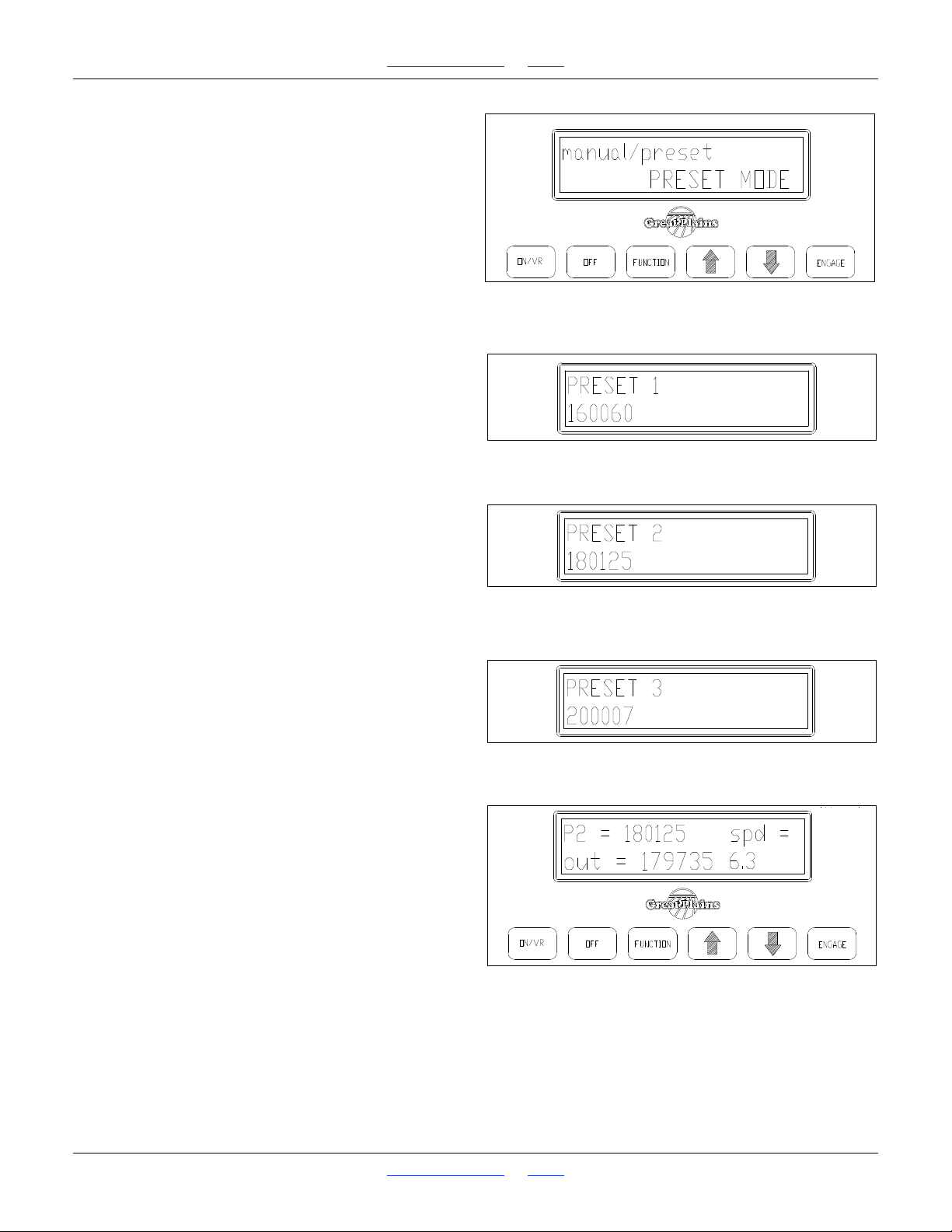
1510HDP, 2010HDP and 2510HDP Table of Contents Index Hydraulic Drive Operation
Figure 99
Preset Mode
22795
Figure 100
Preset Mode 1
22796
Figure 101
Preset Mode 2
22797
Figure 102
Preset Mode 3
22798
Figure 103
Preset Operating Mode
22799
Varying Rates with Pre-set Function
The Great Plains Precision Population Controller allows
you to pre-set three different rates, and then change
rates on-the-go by toggling from one rate to another
rates with the Up or Down arrow keys.
Refer to Figure 99
1. To enter the three pre-set rates, press Function key
until Pre-set Menu screen appears: Use Up-Down
arrow keys to toggle from manual mode to pre-set
mode.
Refer to Figure 100, Figure 101 and Figure 102
2. Press Function key to move to the next pre-set
screen, and the Up-Down arrow keys to set the
pre-set rates.
Refer to Figure 103
3. When in Pre-Set mode, the main operating screen
shows the pre-set rate currently being applied.
When you are in Pre-set mode, the Up-Down arrow
keys only toggle between pre-set rates.
Great Plains | 118-245M | 2018-07-18 Table of Contents Index 87
Page 92
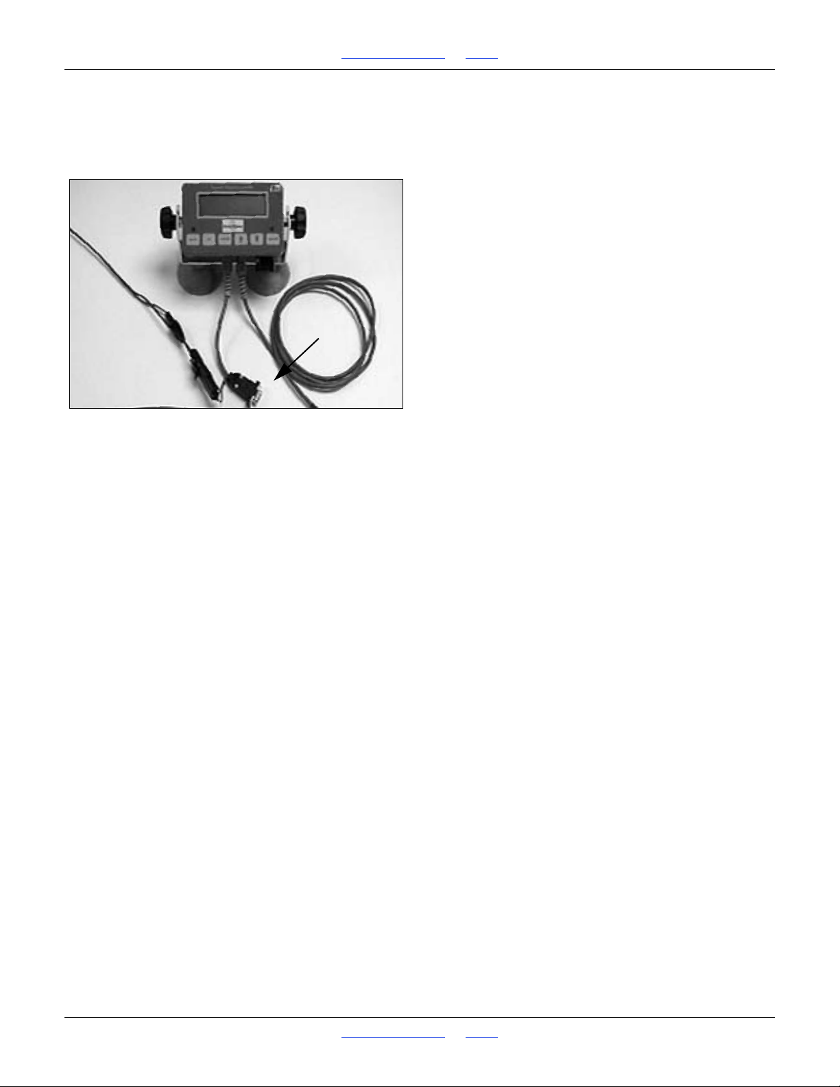
1510HDP, 2010HDP and 2510HDP Table of Contents Index Hydraulic Drive Operation
Figure 104
Serial Connection to Controller
22735
GPS-Based Planting
Both the Farmworks SiteMate computer and the Ag
Leader PF3000 GPS solutions require a 9-pin serial con-
nection to the hydraulic drive controller.
FarmWorks SiteMate
Settings for FarmWorks SiteMate used with Great Plains
Precision Population Controller QUICK REFERENCE
GUIDE
1. Create a .shp recipe file in FarmWorks Site Pro,
SMS 2.0, SSToolbox, or other software that will
create a .shp file, and transfer it to SiteMate.
SiteMate Settings: (version 8.12)
2. Select CONFIGURE Tab.
Select SETTINGS.
Select VARIABLE RATE SETUP.
Select NEW.
Type in GP PPC.
Under CONTROLLER TYPE, select
Rawson from the scroll-down list.
Under COMM PORT select the port number for the
serial card or flash jacket port.
3. Select MAP tab.
Enter DEFAULT rate.
This is the rate that SiteMate calls for if GPS signal is
lost or you are outside the map area.
Note: if GPS signal is interrupted, or if you are out-
side the map area, GP Controller continues applying
rate it was set at when signal was interrupted, until
signal is regained, or another rate is set manually. If
GP Precision Population Settings
1. Connect SiteMate computer to Console using 9-pin
serial cable , as shown above.Follow instructions
on page 70 to set Calibration Number based on row
spacing and metering wheel.
power to the SiteMate is interrupted, restart the recipe to return to VR.
4. In the CONVERSION window, enter the conversion
rate as follows: if your recipe (.shp file) is written
using the entire number as the desired rate, i.e.
30,000 seeds/acre on the recipe means 30,000
seeds/acre is the desired rate, enter both the Map
Unit and Controller Unit as 1.
If the recipe is written using a different number, i.e.
30 on the recipe means a population of 30,000, then
enter the conversion multiple-in that case 1 Map Unit
= 1,000 Controller Units.
5. Under the APP tab,
enter the Feed Delay as 3 seconds.
Enter the Following Distance (the offset from the
Great Plains meters from the GPS) as follows:
for 15ft and 20ft the distance from the opener to the
hitch pin is 18ft;
for the 30ft model the distance is 26ft; Add the
distance from the hitch pin to your GPS location.
Enter the total distance in the Following Distance
window.
Enter the Swath Width of the Great Plains unit.
6. Under the CTRL tab,
enter the Nominal Rate as follows:
Divide the highest rate on your recipe by 1.6.
This is your Nominal rate.
For example, if your highest rate is 200,000 the
nominal is 125,000. If your highest rate is 32, your
nominal rate is 20.
Enter the Step as 4%.
Exit VRA Controller Setup by clicking OK button to
save the settings.
7. Under FILE,
Open VRT and select the
Rx Map (recipe) for the field.
Press the SETUP button and select the
GP PPC controller option that you have set up using
these Settings Instructions.
8. Press GO.
The Rx rate window shows the rate that is being sent
to the GP Precision Population Controller. The
APPLIED window shows the rate that the GP
Controller is applying.
2. Press Function key and go to Rawson mode. Press
Function key until the Nominal Rate appears on the
display. Using the Up/Down arrow keys, set the
Nominal Rate to the same number as you set the
Great Plains | 118-245M | 2018-07-18 Table of Contents Index 88
Page 93

1510HDP, 2010HDP and 2510HDP Table of Contents Index Hydraulic Drive Operation
SiteMate. Once Nominal Rate is set, press Function
key until the main operating screen appears, as
shown in Figure 70 on page 70.
3. Press On/VR key again to toggle to VR mode. VR
should appear on the screen along with the Rate that
is being sent from the SiteMate computer. (See
Figure 97 on page 77). Verify that the rate shown on
the GP Controller Console is the same as the recipe
Troubleshooting with SiteMate
1. No Rx rate appears on SiteMate
• has field been selected? Select VRT file (see
SiteMate Settings, Step 5)
• check recipe to verify that it is valid by viewing
Attributes for each zone in SiteMate
• if recipe calls for zero rate as the default, do you
have GPS signal, or are you outside of field?
2. Rx rate appears on SiteMate, but no Applied Rate.
• make sure “Go” button on SiteMate is pressed.
(button should read “Stop” when recipe is being sent
to GP Console)
• you must be planting in order for Applied Rate to
appear.
3. Rx rate appears on SiteMate but not on GP
Controller Console.
• make sure GP Controller Console is set to VR Mode
(see Figure 98 on page 77).
• double-check all cable connections
• check Nominal rates on both the SiteMate (SiteMate
Settings, Step 4), and on the GP Controller Console
(GP Settings, Step 2) These must be set to the same
number.
4. Rates on GP Controller Console and on SiteMate do
not match.
sent from SiteMate. Press Engage key to activate the
Precision Population Controller.
4. To change rates manually when in VR mode, simply
touch the Up/Down arrow keys. This will change the
Controller to the rate you select manually. To return
to VR, simply touch the On/VR key to toggle back to
VR mode.
5. Population Monitor rate does not match GP
Controller Console.
• Make certain that SiteMate and GP Controller
Console agree. If not, see Troubleshooting step 4.
• Re-check GP calibration number, with metering
wheel and row spacing.
• Re-check planter monitor settings: calibration
number, row spacing, number of rows, swath width,
seed, etc.
• On small seeds and/or high rates, if population
monitor consistently indicates a lower population
than the GP Controller Console, contact monitor
manufacturer for performance specs for that
application.
• GPS signal is not being received by SiteMate:
• verify that GPS serial port (which is also the docking
port) is not set to PC connection only
(Start/Settings/Communications/PC
Connections-check GPS settings in
Configure/Settings/GPS settings/COM (typically
COM1, 4800 Baud, 8 data bits, Parity None, and
Stop Bits 1)
• Click Data tab to view GPS details
• check Nominal rates on both the SiteMate (SiteMate
Settings, Step 4), and on the GP Controller Console
(GP Settings, Step 2) These must be set to the same
number.
• Re-check GP calibration number, with metering
wheel and row spacing.
• The recipe rates from SiteMate are in 4%
increments. If the two rates are within this 4% range,
the units are operating normally.
• Check the Conversion number (SiteMate Settings,
Step 2). If the recipe requires a target conversion
number, i.e. the recipe is for 25 which means 25,000
seeds/acre, the target conversion number will be
1000. In this case the Nominal Rate in SiteMate and
the GP Console should be near 25,000. See
SiteMate Settings, Step 4 for calculating Nominal
Rate.
Great Plains | 118-245M | 2018-07-18 Table of Contents Index 89
Page 94

1510HDP, 2010HDP and 2510HDP Table of Contents Index Hydraulic Drive Operation
Ag Leader PF3000
Settings for Ag Leader PF3000 Monitors used with Great
Plains Precision Population Controller QUICK REFER-
ENCE GUIDE.
1. Create a .tgt recipe file in SMS 2.0 or FarmWorks
Site Pro, or other software that will create a .tgt file,
and copy it to an SRAM or Flash card that is
compatible with the PF 3000.
PF3000 Settings:
2. Press SETUP key.
Press SWATH key.
Set swath to that of your Great Plains Precision
Seeding System.
3. Press SETUP key.
Press VEHICLE key.
Set Primary speed sensor to GPS.
4. Press SETUP key.
Press CARD key.
Set the following:
• Log Device: None.
5. Press SETUP key.
Press APP RATE key.
Set the following:
7. Press SETUP key.
Press PRODUCT key.
Select product and press EDIT SETTINGS.
Set the following:
• Controller Device: Rawson Accu-RateCal. number
for act. rate: set to 0
• Actual Rate Scale Factor: Set to 1.000
• Target Rate Units: Set to Seeds
• Actual Rate Units: Set to Seeds
• Target conversion Number: If your recipe (.tgt file) is
written using the entire number as the desired rate.,
i.e. 30,000 seeds/acre on the recipe means 30,000
seeds/acre is the desired rate, enter a 1.000. If the
recipe is written using a different number, i.e. 30 on
the recipe means a population of 30,000, then you
will need to enter the conversion multiple-in that case
1,000.
• Target Rate increment: Determines the increment
value by which you can change the manual target
rate with each press of the arrow keys.
8. Press FIELD key.
Set Field.
Set Product (press key to right of product)
• Application Control: On
• Look Ahead: On
• Current target file: press Edit to view the files you
have on the card; select the one you wish to use.
6. Press SETUP key.
Press CONTROLLER key.
Select controller as Rawson Accu-Rate.
Press EDIT SETTINGS. Set the following:
• Number of pulses/10 revolutions: 500
• Nominal rate: Divide the highest rate on your recipe
by 1.6. This is your Nominal rate. For example, if
your highest rate is 200,000 the nominal is 125,000.
If your highest rate is 32, your nominal rate is 20.
• Percent rate change: set to 4%
• Area count: Set to Standard
• Stop height: Set to 8
• Act. rate recording method: Set to Sensor
• Controller time delay: Set to 4 sec.
• Application offset from GPS: for 15ft and 20ft the
distance from the opener to the hitch pin is 18ft; for
the 30ft model the distance is 26ft; Add the distance
from the hitch pin to your GPS location.
• Serial Port: Port 3
Troubleshooting with PF3000
1. No Target Rate appears on the PF3000
GP Precision Population Settings
1. Connect PF3000 to Console using 9 pin serial cable
as shown on page 88.
2. Follow instructions on page 70 to set Calibration
Number based on row spacing and metering wheel.
3. Press Function key and
go to Rawson mode.
Press Function key until the Nominal Rate appears
on the display.
Using the Up/Down arrow keys, set the Nominal
Rate to the same number as you set the PF3000 in
step 5 above. Once Nominal Rate is set,
press Function key until the main operating screen
appears.
4. Press On/VR key again to toggle to VR mode. VR
should appear on the screen along with the Rate that
is being sent from the PF3000. (See Figure 84 on
page 73). Verify that the rate shown on the GP
Controller Console is the same as the recipe sent
from the PF3000. Press Engage key to activate the
Precision Population Controller.
5. To change rates manually when in VR mode, simply
touch the Up/Down arrow keys. This will change the
Controller to the rate you select manually. To return
to VR, simply touch the On/VR key to toggle back to
VR mode.
Great Plains | 118-245M | 2018-07-18 Table of Contents Index 90
Page 95

1510HDP, 2010HDP and 2510HDP Table of Contents Index Hydraulic Drive Operation
• has field been selected? Select target file (see
PF3000 Settings, Step 4)
• check recipe to verify that it is valid
• if recipe calls for zero rate as the default, do you
have GPS signal, or are you outside of field?
2. No Actual Rate appears on the PF3000.
• actual rate cannot be logged using the PF3000 with
the Great Plains Precision Population Controller.
3. Target Rate appears on PF3000 but not on GP
Controller Console.
• make sure GP Controller Console is set to VR Mode
(see Figure 97 page 77).
• double-check all cable connections
• check Nominal rates on both the PF3000 (PF3000
Settings, Step 5), and on the GP Controller Console
(GP Settings, Step 2) These must be set to the same
number.
4. Rates on GP Controller Console and on PF3000 do
not match.
• check Nominal rates on both the PF3000 (PF3000
Settings, Step 5), and on the GP Controller Console
(GP Settings, Step 2) These must be set to the same
number.
• Re-check GP calibration number, with metering
wheel and row spacing.
• The recipe rates from the PF3000 are in 4%
increments. If the two rates are within this 4% range,
the units are operating normally.
• Check the target conversion number (PF3000
Settings, Step 6). If the recipe requires a target
conversion number, i.e. the recipe is for 25 which
means 25,000 seeds/acre, the target conversion
number will be 1000. In this case the Nominal Rate
on the PF3000 and on the GP Console should be
near 25,000. See PF 3000 Settings, Step 5 for
calculating Nominal Rate.
5. Population Monitor rate does not match GP
Controller Console.
• Make certain that PF3000 and GP Controller
Console agree. If not, see Troubleshooting step 4
above.
• Re-check GP calibration number, with metering
wheel and row spacing.
• Re-check planter monitor settings: calibration
number, row spacing, number of rows, swath width,
seed, etc.
• When planting small size seeds and/or at high rates,
if population monitor consistently indicates a lower
population than the GP Controller Console, contact
monitor manufacturer for performance specs for that
application.
Great Plains | 118-245M | 2018-07-18 Table of Contents Index 91
Page 96
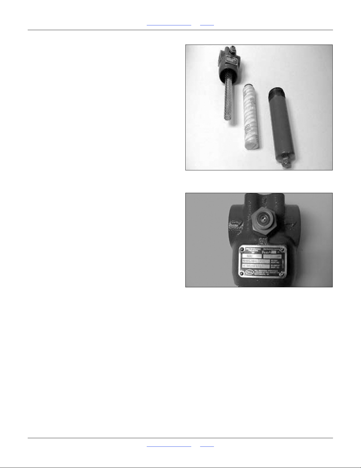
1510HDP, 2010HDP and 2510HDP Table of Contents Index Hydraulic Drive Operation
Figure 105
Hydraulic Filter
22736
Figure 106
Hydraulic Filter Indicator
22737
Hydraulic Drive Maintenance
As with any hydraulic system, contamination is the most
common cause of performance problems and
pre-mature wear. Make a special effort to properly clean
quick couplers prior to attaching the hoses to tractor.
Filter: All fluid is filtered through the high pressure filter
(p/n 18574) and it provides protection to the hydraulic
components of your drive if properly maintained. It is
equipped with a pop-out indicator to alert that the
replaceable element is clogged, and should be changed
immediately if this situation occurs. Normal service life of
the element will vary based on the precautions that you
take to minimize contamination at the couplers and
routine service of the tractor filtration.
To change the element:
Refer to Figure 105
1. Un-screw lower canister from filter, catching and
disposing of used fluid.
2. Remove and discard element.
3. Install new element (p/n 19856)
4. Clean canister threads and lube o-ring with hydraulic
fluid, then re-install.
Refer to Figure 106
5. Re-set pop-out indicator if necessary.
It is a good idea to keep a filter element on hand, and we
recommend changing at a minimum on an annual basis.
6. Between planting seasons, store cab console inside
in a relatively stable and dry environment.
7. Avoid direct spray from high pressure washers on
the motor encoder and the external controller box.
These units are sealed from normal moisture, but
high pressure could inject water into the housing.
8. Keep electrical connects free from dirt and grease.
It’s a good idea to occasionally spray the terminals
with contact cleaner to ensure proper connection.
Great Plains | 118-245M | 2018-07-18 Table of Contents Index 92
Page 97

1510HDP, 2010HDP and 2510HDP Table of Contents Index Hydraulic Drive Operation
Hydraulic Drive Troubleshooting
Drive will not rotate:
(see Troubleshooting Flow Chart and Electronics Overview)
1. Check cab console:
a. No power to cab console - check with voltmeter.
b. Upper line (set) is visible but no lower line (out
rate and speed) on display: move to Communication troubleshooting below.
c. 1 or 10 amp fuse on power cable may be blown.
d. Engage button is not on - check to see if green
indicator light is on.
e. Use Cab Console Power Tester (p/n 27857) to
check power out of cab console. Install tester on
round 7-pin power/com cable from cab console.
Turn drive on. Green LED shows power to external controller. Red LED shows power to solenoid. If LED lights are not lit, double-check power
and connections; replace cab console if needed.
2. Check communication between cab console and
drive:
a. Check to see if power and communication cable
(main harness) is properly connected.
b. If no lower line on cab console appears (speed
and output rate), and drive will not rotate in calibration mode, use Cable Continuity Tester (p/n
27859) to test power and communication to
external controller. (WARNING: TO PREVENT
DAMAGE TO COMPONENTS, DISCONNECT
POWER/COM CABLE FROM CAB CONSOLE
AND EXTERNAL CONTROLLER BEFORE
INSTALLING THIS TESTER). Install 4-pin test
plug on end of 4-pin power/com cable before
powering the Cable Continuity Tester - remove
before reattaching power/com cable directly to
cab console.
c. If Cable Continuity Tester shows power is getting
to external controller, turn power off and remove
Cable Continuity Tester and 4-pin test plug from
ends of power/com cable. Reattach power/com
cable to cab console and external controller.
d. If power/com cable tester shows power and com-
munication is reaching external controller from
cab console, and no lower line appears on cab
console, replace chip or external controller. Call
Service Department.
e. If Cable Continuity Tester (p/n 27859) isn’t avail-
able, check cable with voltmeter at connection at
control module.
3. Test Relay inside external controller:
a. Use Relay Output Tester (p/n 27860) to test relay
inside external controller. Install tester to
weather-pak solenoid connector from external
controller. With tractor engine off, start drive calibration function. Auditory alarm should buzz for
1.5 seconds when drive is engaged in calibration
mode. If alarm does not sound, relay or external
controller may need to be replaced. Call Service
Department.
4. Check hydraulics:
a. Check to see if hydraulic lever is in detent posi-
tion.
b. Hydraulic lever is in wrong detent direction - a
check valve at outlet of motor prevents reverse
rotation.
c. Make sure that both hoses are properly con-
nected to tractor remotes.
d. Inadequate system pressure. Place pressure
gauge at filter and check reading. If system pressure is below tractor specifications, check system.
e. Power solenoid directly:
Rapid drive rotation may occur and cause serious injury.
i. Disengage hydraulics.
ii. Reduce flow to 30-50%.
iii. Power solenoid directly by connecting power
weather-pak connector to solenoid
weather-pak connector. If drive doesn’t
rotate, Proportional Coil (p/n 19799) may be
defective. Check continuity with meter, or
energize with 12v power and check for magnetic pull with small screwdriver. Double-check connections on solenoid cable. If
solenoid energizes but drive does not rotate
when powered directly, tractor hydraulics are
not properly engaged.
f. Excessive torque in drive system. Disconnect
main drive chain to check for rotation under zero
load. Check for a problem with the mechanical
portion of drive, such as foreign material wedged
Great Plains | 118-245M | 2018-07-18 Table of Contents Index 93
Page 98

1510HDP, 2010HDP and 2510HDP Table of Contents Index Hydraulic Drive Operation
in meter, frozen bearings, misaligned chains, or
swelled grain in meter. Install pressure gauge at
motor inlet. Pressure should be 1000-1500 psi. If
pressure is above 2000 psi, significant torque
problems are present.
5. Check Speed signal (if drive rotates in calibration
mode but not when planting)
Rapid drive rotation may occur and cause serious injury.
a. No signal from speed sensor - check connection
at sensor and at drive controller.
b. Excessive gap between wheel sensor and sen-
sor plate - readjust to .030.
c. Use Speed Simulator (p/n 27858) to trouble-
shoot speed loop. Leave tractor stationary and
drive hydraulics do not need to be engaged.
d. Test speed sensor and hall effect sensor;
replace sensor if simulated speed appears on
cab console.
e. Test speed cable between speed sensor and hall
effect module; replace cable if simulated speed
appears on cab console.
f. Test hall effect module and cable to external con-
troller; replace module and cable if simulated
speed appears on cab console. If speed does
not appear with speed simulator, external controller or chip may need replacement. Call Service Department.
Drive rotates but not at desired speed:
1. Drive (out rate) fluctuating erratically:
a. If indicated field speed on drive is also fluctuat-
ing erratically, troubleshoot speed signal loop.
b. If field speed is steady, check for loose set
screws on motor encoder, contamination of proportional valve, or mechanical binding of chain
on row unit.
2. Indicated speed fluctuating erratically:
a. Use speed simulator to troubleshoot speed loop.
Leave tractor stationary and drive hydraulics do
not need to be engaged. If steady speed
between 4-10 mph appears on cab console
using speed simulator, troubleshoot radar, wheel
pickup sensor, hall effect module. If steady
speed does not appear with speed simulator,
external controller may need replacement. Call
Service Department.
b. Check radar gun angle.
c. Check gap between wheel sensor and pickup
plate.
d. Check power to system < 12 volt power will
cause drive to behave erratically - often problem
manifests itself in speed loop.
3. Drive shuts off while planting:
a. If it occurs after 20 seconds of not planting, such
as turning on headlands, operation is normal
safety shutoff (on units with radar speed signal).
b. Check setting of speed signal interrupter switch -
reposition as necessary to keep actuator from
disengaging while planting.
c. 1.5 second delay shutting off drive- causes:
chain binding, inadequate hydraulics.
4. Drive will not achieve desired rate:
a. Recheck calibration number and rerun calibra-
tion procedure if necessary.
b. Check to make sure that your desired rate is
within the range of the meter that is installed.
c. Inadequate hydraulic flow. Adjust flow control to
higher position. Check with flow meter if flow is
suspect.
d. Field speed too high. Check maximum planting
rate in seed chart for rate that you are planting.
e. Check sprocket combinations; see Assembly
and Parts Manuals for the planter you are operating (30P and 40P models).
f. Check speed shown on cab console against
other speedometer - tractor, planter monitor. If
drive speed is significantly lower, recalibrate
speed on drive.
5. Drive plants significantly higher than desired rate:
a. Recheck calibration number and re-run calibra-
tion procedure if necessary.
b. Ensure that you have installed the correct seed
meter.
c. Check sprocket combinations; see Assembly
and Parts Manuals for the planter you are operating (30P and 40P models).
d. Check speed shown on cab console against
other speedometer - tractor, planter monitor. If
drive speed is significantly higher, recalibrate
speed on drive.
6. Drive continues to rotate after tractor has stopped:
Great Plains | 118-245M | 2018-07-18 Table of Contents Index 94
Page 99
1510HDP, 2010HDP and 2510HDP Table of Contents Index Hydraulic Drive Operation
a. Contamination or wear in proportional valve (p/n
19798). Remove and inspect. Blow out with
compressed air. Check o-rings and reinstall.
Replace if necessary.
Calibration Troubleshooting:
If the time to run for calibration is less than 4 seconds,
the cab console will display TIME TOO LOW.
Pressing the FUNCTION key will bring up the ENTER
TARGET AMOUNT screen. The target should be raised
to increase the calibration time. If the time is greater than
255 seconds, the cab console will display TIME TOO
HIGH. Pressing the FUNCTION key will bring up the
ENTER TARGET AMOUNT screen. The target should be
lowered to decrease the calibration time.
7. Fluid weeping from motor shaft seal:
a. Excessive back pressure in return hose. Check
quick coupler connection. Use motor control port
for return if available.
While rate calibration is running, one of four error messages may be displayed:
Message Cause Solution
Check power and
COMM
TIMEOUT
TIME
OVER
LIMIT
USER
TERMINATED
CALIBRATE
ERROR
Power to or communication with the
external controller
was interrupted
during calibration.
The external ran too
long in calibration.
The engage key was
pressed during calibration.
The drive did not
turn when calibration began.
communication
connections from
the cab console to
the external controller and rerun
calibration.
Rerun calibration.
If the same message appears, call
technical support.
Rerun calibration.
Check encoder
cable and connection, solenoid
cable and connection, and hydraulic
lever position.
Great Plains | 118-245M | 2018-07-18 Table of Contents Index 95
Page 100
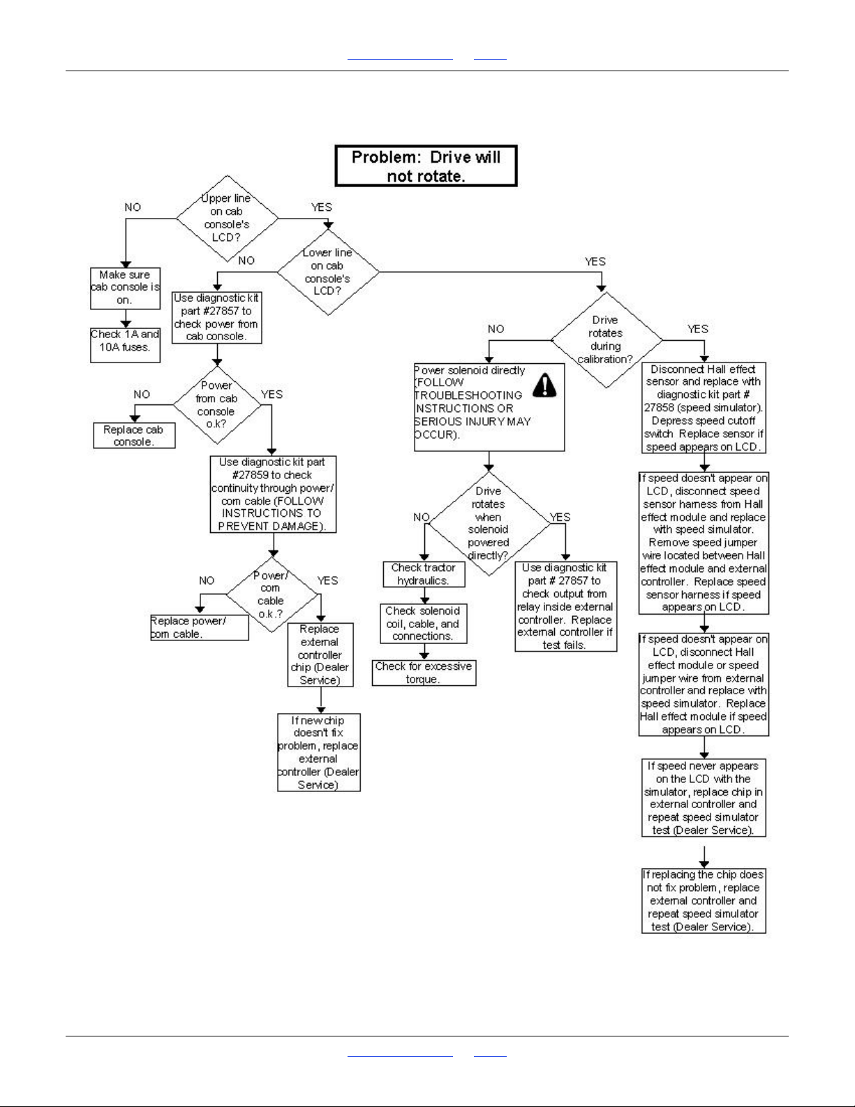
1510HDP, 2010HDP and 2510HDP Table of Contents Index Hydraulic Drive Operation
23250
Hydraulic Drive Troubleshooting Flow Chart
Great Plains | 118-245M | 2018-07-18 Table of Contents Index 96
 Loading...