

Page 1

Chariot
GDRZ25KAE, GDRZ25KHE, GDRZ26KHE
D02-105
GD10001
B2
OPERATOR’S MANUAL
c WARNING: The Engine Exhaust
from this product contains chemicals known
to the State of California to cause cancer,
birth defects or other reproductive harm.
California Proposition 65 Warning
OMGD10001 B2
North American Version
Litho in U.S.A.
Page 2
INTRODUCTION
Introduction
Using Your Operator’s Manual
This manual is an important part of your machine and
should remain with the machine when you sell it.
An engine manufacturer’s owner’s manual has been
provided with your machine. This will provide maintenance
and troubleshooting information for the engine installed in
your machine.
Reading your operator’s manual will help you and others
avoid personal injury or damage to the machine.
Information given in this manual will provide the operator
with the safest and most effective use of the machine.
Sections in your operator’s manual are placed in a specific
order to help you understand all the safety messages and
learn the controls so you can operate this machine safely.
You can also use this manual to answer any specific
operating or servicing questions.
The machine shown in this manual may differ slightly from
your machine, but will be similar enough to help you
understand our instructions.
RIGHT-HAND and LEFT-HAND sides are determined by
facing in the direction the machine will travel when going
forward. When you see a broken line (------), the item
referred to is hidden from view.
GDRZ26KHE Serial No. (459000 - 460999)
If you need to contact an Authorized Service Center for
information on servicing, always provide the product model
and serial numbers.
You will need to locate the model and serial numbers for
the machine and for the engine of your machine and record
the information in the spaces provided.
DATE OF PURCHASE:
_________________________________________
DEALER NAME:
_________________________________________
DEALER PHONE:
_________________________________________
B
Special Messages
Your manual contains special messages to bring attention
to potential safety concerns, machine damage as well as
helpful operating and servicing information. Please read all
the information carefully to avoid injury and machine
damage.
c CAUTION: Avoid injury! This symbol and text
highlight potential hazards or death to the
operator or bystanders that may occur if the
hazards or procedures are ignored.
IMPORTANT: Avoid damage! This text is used to tell
the operator of actions or conditions that might
result in damage to the machine.
NOTE: General information is given throughout the
manual that may help the operator in the operation or
service of the machine.
Record Identification Numbers
Chariot
GDRZ25KAE Serial No. (455000 - 455999)
C
MODEL NUMBER (A):
__ __ __ __ __ __ __ __ __ __ __ __ __ __ __ __ __
SERIAL NUMBER (POWER UNIT) (B):
__ __ __ __ __ __ __ __ __ __ __ __ __ __ __ __ __
ENGINE SERIAL NUMBER (B):
__ __ __ __ __ __ __ __ __ __ __ __ __ __ __ __ __
ENGINE SPECIFICATION NUMBER (C):
__ __ __ __ __ __ __ __ __ __ __ __ __ __ __ __ __
A
MX9204
GDRZ25KHE Serial No. (457000 - 458999)
Introduction
Page 3

TABLE OF CONTENTS
Table of Contents
Safety .....................................................................................................................................................................................1
Operating................................................................................................................................................................................ 6
Replacement Parts ...............................................................................................................................................................10
Service Intervals...................................................................................................................................................................11
Service Lubrication...............................................................................................................................................................12
Service Engine .....................................................................................................................................................................13
Service Transmission............................................................................................................................................................15
Service Mower......................................................................................................................................................................18
Service Electrical..................................................................................................................................................................23
Service Miscellaneous..........................................................................................................................................................26
Troubleshooting ....................................................................................................................................................................28
Storage.................................................................................................................................................................................31
Assembly..............................................................................................................................................................................32
Specifications .......................................................................................................................................................................34
Index.....................................................................................................................................................................................35
Service Record GD ..............................................................................................................................................................36
All information, illustrations and
specifications in this manual are based
on the latest information at the time of
publication. The right is reserved to
make changes at any time without
John Deere Worldwide Commercial and
Consumer Equipment Division
notice.
COPYRIGHT© 2002
Deere & Co.
All rights reserved
Previous Editions
COPYRIGHT© 2001
OMGD10001 B2 - English
Table of Contents
Page 4
SAFETY
Safety
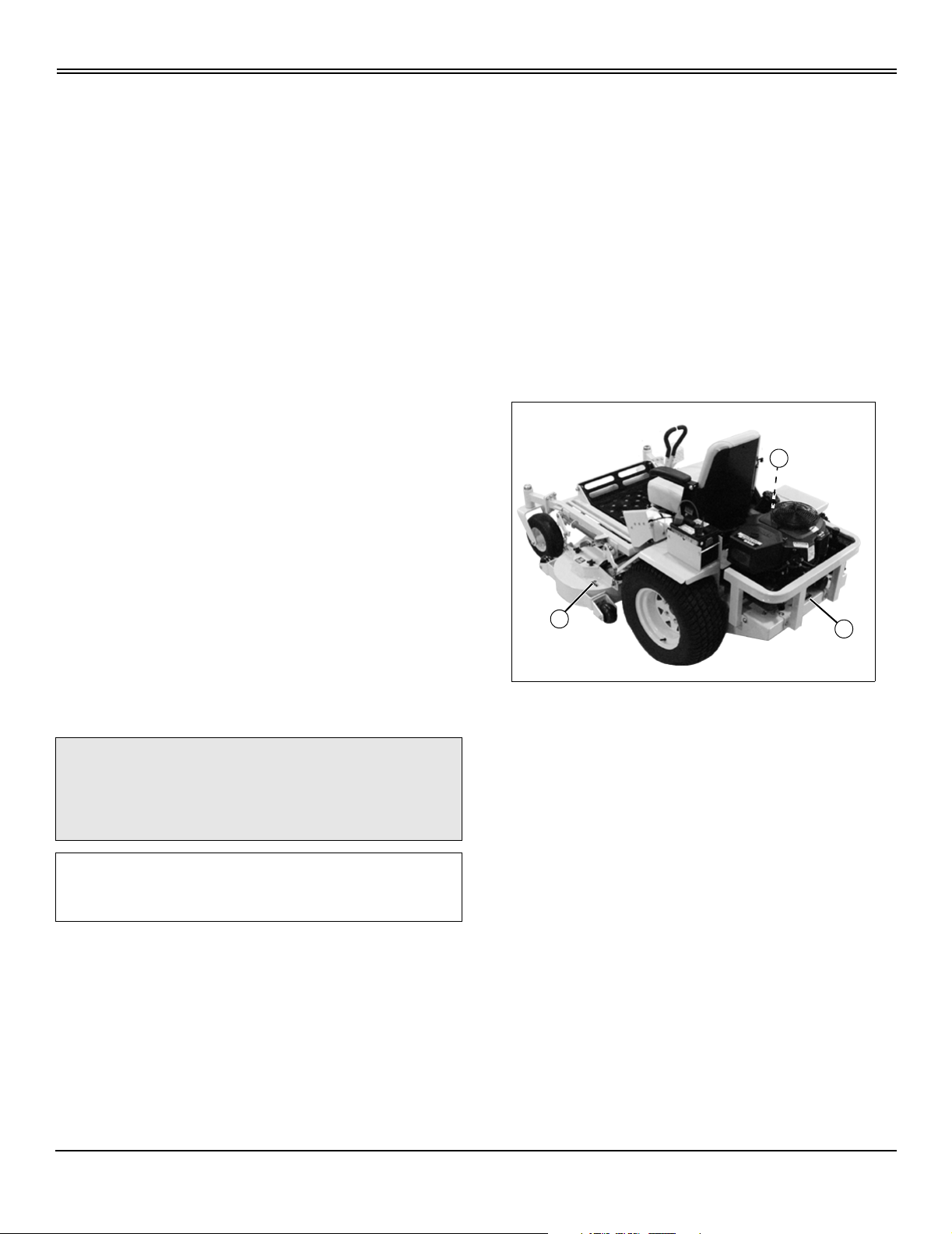
Understanding The Machine Safety Labels
MIF
The machine safety labels shown in this section are placed
in important areas on your machine to draw attention to
potential safety hazards.
On your machine safety labels, the words DANGER,
WARNING, and CAUTION are used with this safety-alert
symbol. DANGER identifies the most serious hazards.
The operator’s manual also explains any potential safety
hazards whenever necessary in special safety messages
that are identified with the word, CAUTION, and the safetyalert symbol.
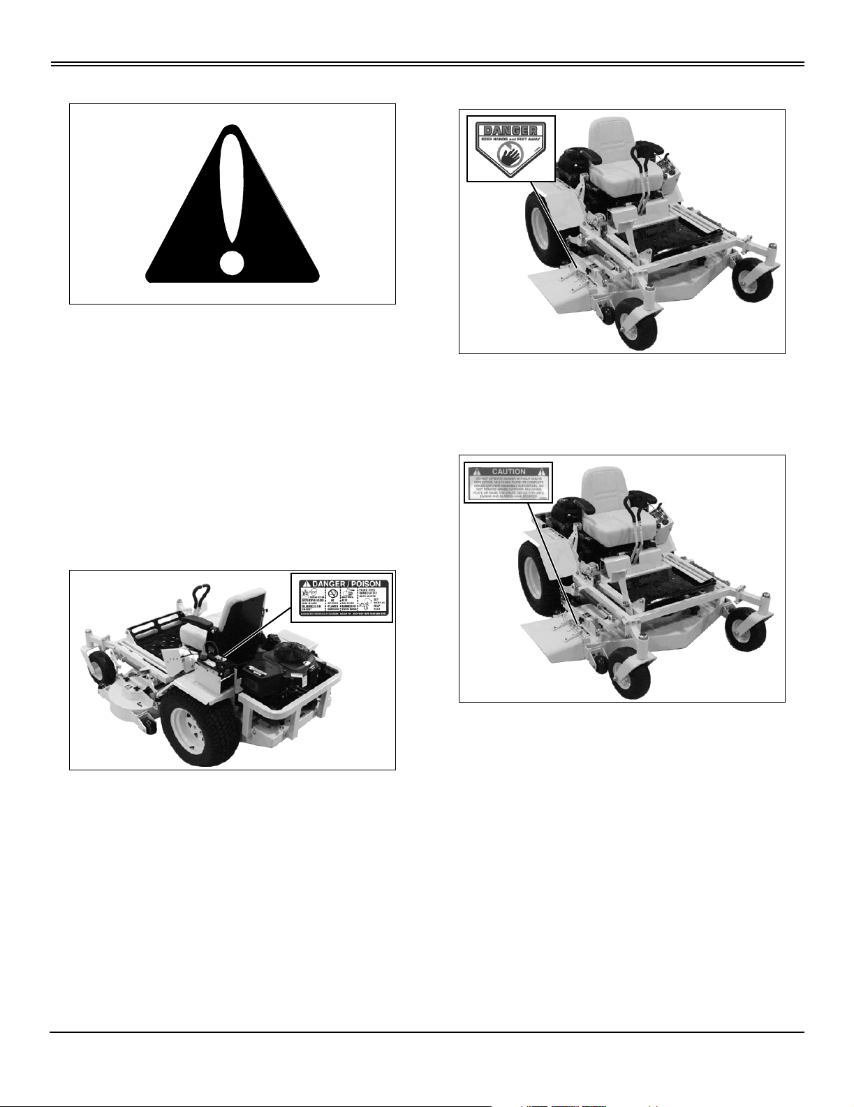
DANGER
MX9293 MX9214
• Keep hands and feet away.
CAUTION
DANGER/POISON
MX9292 MX9204
• Shield eyes, explosive gases can cause blindness or
injury.
• No sparks, flames, smoking.
• Sulfuric acid can cause blindness or severe burns.
• Flush eyes immediately with water, get medical help
fast.
• Keep out of the reach of children.
MX9294 MX9214
• Do not operate mower without chute deflector, mulching
plate or complete grass catcher assembly in position.
• Do not remove grass catcher, mulching plate or raise
the chute deflector until engine and blade(s) have stopped.
• Do not tip.
• Keep vent caps tight and level.
Safety - 1
Page 5
SAFETY
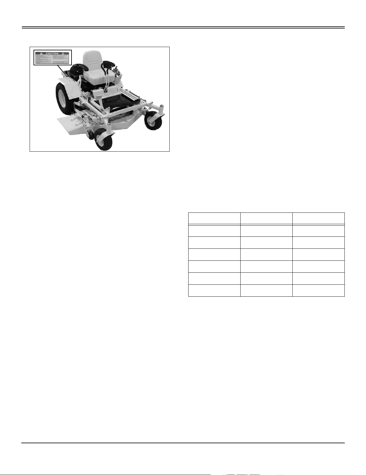
CAUTION
MX9295 MX9214
• This product is designed for professional and
commercial users.
• Operation training is required.
• Carefully read safety instructions.
• Know function of controls before operating.
• Practice with cutter blades off until confident.
• Clear mowing area of all debris.
• Keep all guards, covers and shields in place while
working.
• Do not disable or bypass any safety device.
• Always wear safety goggles while operating.
• Always park machine on level surface.
• Avoid contact with cutter blades. They may be rotating.
• Keep children and others clear from area.
• Set ground speed control to safe speed.
• Slowly and smoothly move speed control levers to start
and stop machine.
• Reduce speed and avoid sharp turns.
• Be careful on slopes, do not mow where stability or
traction is in doubt.
• To obtain additional operator manual and safety
instructions, contact your Great Dane dealer or write Great
Dane Power Equipment, 4700 New Middle Rd.,
Jeffersonville, IN 47130, USA.
Emission Control System Certification Label (Small Off-Road Gas Engines)
NOTE: Tampering with emission controls and
components by unauthorized personnel may result in
severe fines or penalties. Emission controls and
components can only be adjusted by EPA and/or
CARB authorized service centers. Contact your Great
Dane Equipment Retailer concerning emission
controls and component questions.
The presence of an emissions label signifies that the
engine has been certified with the United States
Environmental Protection Agency (EPA) and/or California
Air Resources Board (CARB).
The emissions warranty applies only to those engines
marketed by Great Dane that have been certified by the
EPA and/or CARB; and used in the United States and
Canada in off-road mobile equipment.
Emission Compliance Period (Small Off-Road Gas Engines)
If your engine has the emission compliance category listed
on the emission control system certification or air index
label, this indicates the number of operating hours for
which the engine has been certified to meet EPA and/or
CARB emission requirements. The following table provides
the engine compliance period in hours associated with the
category found on the certification label.
Agency Category Hours
EPA C 250
EPA B 500
EPA A 1000
CARB Moderate 125
CARB Intermediate 250
CARB Extended 500
Operating Safely
• Inspect machine before you operate. Be sure hardware
is tight. Repair or replace damaged, badly worn, or missing
parts. Be sure guards and shields are in good condition
and fastened in place. Make any necessary adjustments
before you operate.
• Do not operate mower without discharge chute or entire
grass catcher in place.
• Check before each use that operator presence controls
are functioning correctly. Test safety systems. Do not
operate unless they are functioning correctly.
• Do not change the engine governor setting or
overspeed the engine.
• Check brake action before you operate. Adjust or
service brakes as necessary.
Safety - 2
Page 6
SAFETY
• Stop machine if anyone enters the area.
• Never raise mower decks when blades are running.
• If you hit an object, stop and inspect the machine. Make
repairs before you operate. Keep machine and
attachments properly maintained and in good working
order.
• Do not leave machine unattended when it is running.
• Only operate during daylight or with good artificial light.
• Slow down and be careful of traffic when operating near
or crossing roadways. Stop blades before crossing roads
or sidewalks. Use care when approaching blind corners,
shrubs, trees, or other objects that may obscure vision.
• Be aware of the mower discharge direction and make
sure that no one is in the path of the discharge direction.
• Use only accessories and attachments approved by the
manufacturer of the machine.
• Wear close fitting clothing and safety equipment
appropriate for the job.
• Always wear safety goggles or safety glasses with side
shields when operating the mower.
• Wear a suitable protective device such as earplugs.
Loud noise can cause impairment or loss of hearing.
• Do not wear radio or music headphones. Safe service
and operation requires your full attention.
Checking Mowing Area
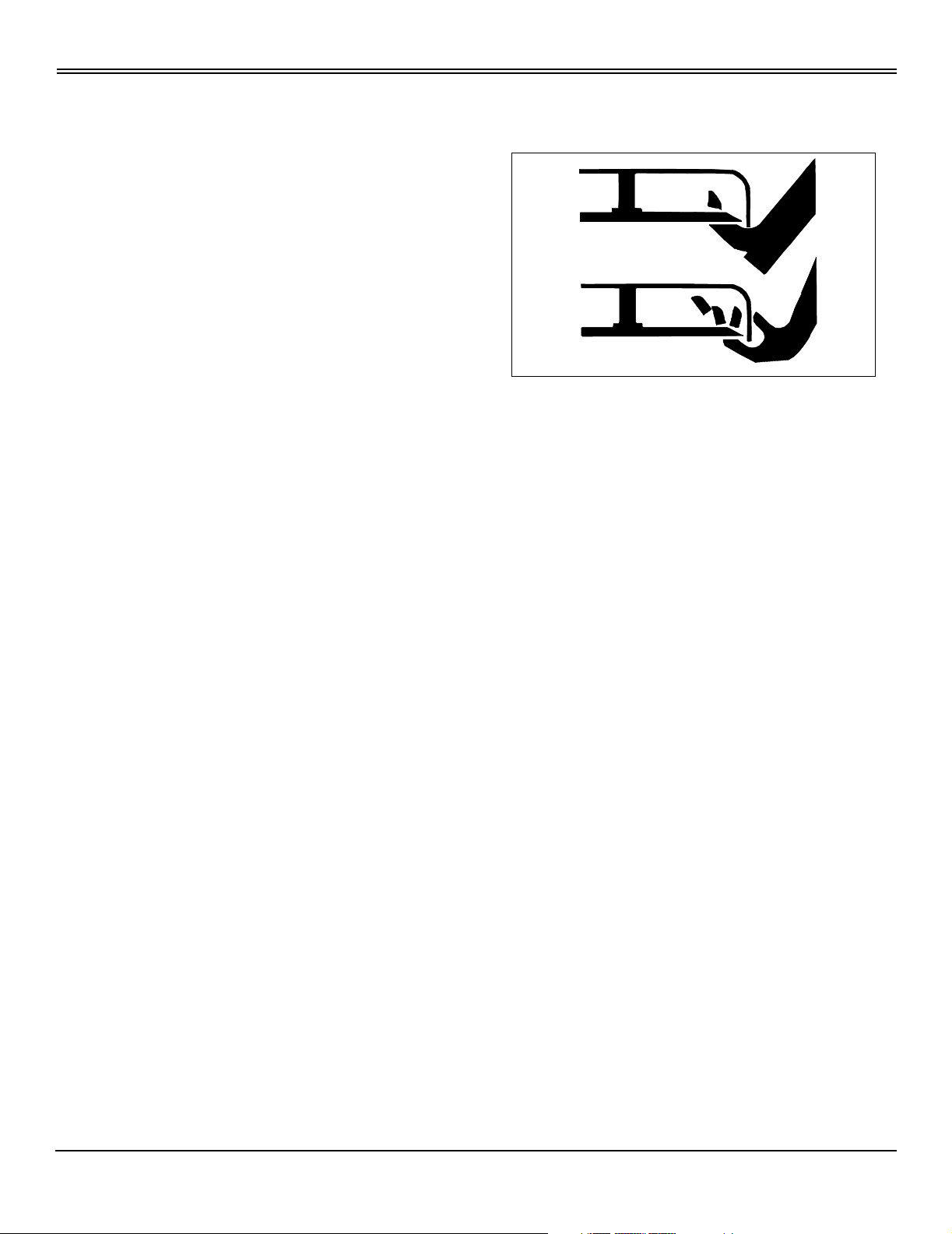
Rotating Blades are Dangerous
HELP PREVENT SERIOUS OR FATAL ACCIDENTS:
MIF
• Rotating blades can cut off arms and legs.
• Keep hands, feet and clothing away from mower deck
when engine is running.
• Be alert at all times, drive forward carefully. People,
especially children can move quickly into the mowing area
before you know it.
• Before backing up, shut off PTO and look down and
behind the machine carefully, especially for children.
• Do not mow in reverse.
• Shut off blades when you are not mowing.
• Do not operate machine if you are under the influence of
drugs or alcohol.
• Evaluate the terrain to determine what accessories and
attachments are needed to properly and safely perform the
job.
• Clear mowing area of objects that might be thrown.
Keep people and pets out of mowing area.
• Study mowing area. Set up a safe mowing pattern. Do
not mow where traction or stability is doubtful.
• Test drive area with mower lowered but not running.
Slow down when you travel over rough ground.
Parking Safely
1. Stop machine on a level surface, not on a slope.
2. Disengage PTO.
3. Lower attachments to the ground.
4. Lock park brake.
5. Stop engine.
6. Remove key.
7. Wait for engine and all moving parts to stop before you
leave the operator’s station.
• Park machine safely before inspecting or unplugging
mower or bagger.
PROTECT CHILDREN:
• Never assume that children will remain where you last
saw them. Children are attracted to mowing activity, stay
alert to the presence of children.
• Keep children indoors when you are mowing. Turn the
machine off if a child enters the mowing area.
• Use extra care when you come to blind corners, shrubs,
trees, or other objects that may block your vision.
• Do not let children or an untrained person operate the
machine.
• Do not carry or let children ride on any attachment or
machine even with the blades off. Do not tow children in a
cart or trailer.
Avoid Tipping
• Slopes are a major factor related to loss-of-control and
tip-over accidents, which can result in severe injury or
death.
Safety - 3
Page 7

SAFETY
• Drive across a hill - not up and down. If necessary, turn
slowly and in the downhill direction. Do not shift to neutral
and coast downhill.
• Avoid starting and stopping on a slope. If machine
stops, disengage mower blades and back down slowly.
• Do not drive where machine could slip or tip.
• Stay alert for holes and other hidden hazards in the
terrain.
• Keep away from drop-offs, ditches, and embankments.
• Slow down before you make a sharp turn or operate on
a slope. On gear models, choose a low gear so that shifting
and stopping will not be necessary while on the slope.
• Transport machine with decks lowered to improve
stability.
• Drive machine very slowly and avoid quick stops when
attachment is removed.
• Mowing when grass is wet can cause reduced traction
and sliding.
Keep Riders Off
• Only allow the operator on the machine. Keep riders off.
• Riders on the machine or attachment may be struck by
foreign objects or thrown off the machine causing serious
injury.
• Riders obstruct the operator’s view resulting in the
machine being operated in an unsafe manner.
Checking Wheel Bolts
• A serious accident could occur causing serious injury if
wheel bolts are not tight.
• Check wheel bolt tightness often during the first 100
hours of operation.
• Wheel hardware must be tightened to specified torque
using the proper procedure anytime it is loosened.
Driving Safely on Public Roads
Avoid personal injury or death resulting from a collision with
another vehicle on public roads:
• Use safety lights and devices. Slow moving machines
when driven on public roads are hard to see, especially at
night.
• Use extra care when loading or unloading the machine
into a trailer or truck.
• Whenever driving on public roads, use flashing warning
lights and turn signals according to local regulations. Extra
flashing warning lights may need to be installed.
Practice Safe Maintenance
• Only qualified, trained adults should service this
machine.
• Understand service procedure before doing work. Keep
area clean and dry.
• Never lubricate, service, or adjust machine while it is
moving. Keep safety devices in place and in working
condition. Keep hardware tight.
• Keep hands, feet, clothing, jewelry, and long hair away
from any moving parts, to prevent them from getting
caught.
• Lower attachments to the ground before servicing
machine. Disengage all power and stop the engine. Lock
park brake and remove the key. Let machine cool.
• Disconnect battery or remove spark plug wire before
making any repairs.
• Before servicing machine, carefully release pressure
from components with stored energy such as hydraulic
components.
• Keep all nuts and bolts tightened, especially blade
attachment bolts.
• Securely support any machine elements that must be
raised for service work. Lock service latches before
working on machine with raised attachments.
• Never run engine unless park brake is locked.
• Keep all parts in good condition and properly installed.
Fix damage immediately. Replace worn or broken parts.
Replace all worn or damaged safety and instruction decals.
• To prevent fires, remove any buildup of grease, oil, or
debris from the machine, especially the engine
compartment.
• Charge batteries in an open, well-ventilated area, away
from sparks. Unplug battery charger before connecting or
disconnecting from the battery. Wear protective clothing
and use insulated tools.
• Do not modify machine or safety devices. Unauthorized
modifications may impair its function and safety.
• Do not wear radio or music headphones while servicing
the machine. Safe service requires your full attention.
Avoid High Pressure Fluids
• Hydraulic hoses and lines can fail due to physical
damage, kinks, age, and exposure. Check hoses and lines
regularly. Replace damaged hoses and lines.
• Hydraulic fluid connections can loosen due to physical
Safety - 4
Page 8
SAFETY
damage and vibration. Check connections regularly.
Tighten loose connections.
• Escaping fluid under pressure can penetrate the skin
causing serious injury. Avoid the hazard by relieving
pressure before disconnecting hydraulic or other lines.
Tighten all connections before applying pressure.
• Search for leaks with a piece of cardboard. Protect
hands and body from high pressure fluids.
• If an accident occurs, see a doctor immediately. Any
fluid injected into the skin must be surgically removed
within a few hours or gangrene may result. Doctors
unfamiliar with this type of injury should reference a
knowledgeable medical source.
Prevent Fires
• Never remove fuel cap, or add fuel with engine running
or hot. Allow engine to cool for several minutes.
• Never store equipment with fuel in the tank inside a
building where fumes may reach an open flame or spark.
• Allow engine to cool before storing in any enclosure.
• To reduce fire hazard, keep engine free of grass,
leaves, or excessive grease.
running.
• Never fill fuel tank or drain fuel from a machine in an
enclosed area. Fill fuel tank outdoors.
• Prevent fires. Clean up spilled fuel immediately.
• Do not store machine with fuel in tank in a building
where fumes may reach an open flame or spark.
• Prevent fire and explosion caused by static electric
discharge. Use only non-metal, portable fuel containers
approved by the Underwriter’s Laboratory (U.L.) or the
American Society for Testing & Materials (ASTM). If using
a funnel, make sure it is plastic and has no screen or filter.
Tire Safety
Explosive separation of a tire and rim parts can cause
serious injury or death:
• Do not attempt to mount a tire without the proper
equipment and experience to perform the job.
• Always maintain the correct tire pressure. Do not inflate
the tires above the recommended pressure. Never weld or
heat a wheel and tire assembly. The heat can cause an
increase in air pressure resulting in a tire explosion.
Welding can structurally weaken or deform the wheel.
• When inflating tires, use a clip-on chuck and extension
hose long enough to allow you to stand to one side and not
in front of or over the tire assembly.
• Check tires for low pressure, cuts, bubbles, damaged
rims or missing lug bolts and nuts.
Handling Fuel Safely
Fuel and fuel vapors are highly flammable and explosive:
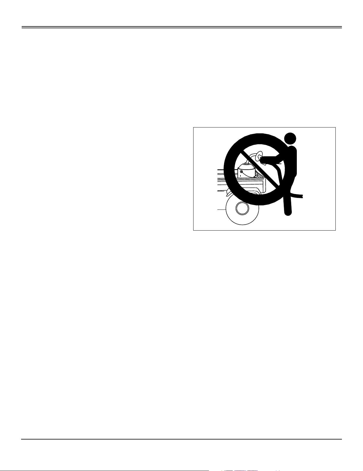
• Do not refuel machine while you smoke, when machine
is near an open flame or sparks, or when engine is running.
Stop engine and allow to cool before filling.
• Never remove the fuel cap or add fuel with the engine
MIF
• Static electric discharge can ignite gasoline vapors in an
ungrounded fuel container. Remove the fuel container from
the bed of a vehicle or the trunk of a car and place on the
ground away from the vehicle before filling. Keep nozzle in
contact with container opening while filling.
• When practical, remove equipment from trailers or truck
beds and refuel them on the ground. If this is not possible,
use a portable, plastic fuel container to refuel equipment on
a truck bed or trailer.
• For gasoline engines, do not use gas with methanol.
Methanol is harmful to your health and to the environment.
Safety - 5
Page 9
OPERATING
Operating
Daily Operating Checklist
❏ Test safety systems.
❏ Check tire pressure.
❏ Check fuel level.
❏ Check engine oil level.
❏ Remove and clean engine air filter.
❏ Check transmission oil reservoir level.
❏ Remove grass and debris from machine.
❏ Clean engine cooling air intake screen and cooling fins.
❏ Inspect all belts for damage.
❏ Sharpen and balance mower blades.
❏ Check area below machine for any fuel or oil leaks.
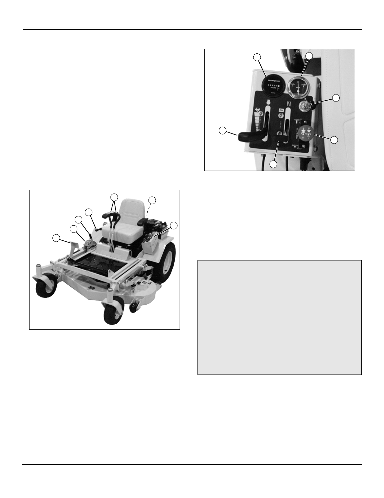
Operating Controls
F
A
D
B
C
E
G
Console Controls
A
A - Throttle Lever
B - Key Switch
C - Choke Lever
D - PTO/Clutch Switch
E - Hourmeter
F- Ammeter
E
C
F
B
D
MX9205
MX9206
A - Park Brake Lever
B - Height-of-Cut (HOC) Adjustment Pin
C - Mower Deck Lift/Lower Pedal
D - Mower Deck Transport Position Lock Lever
E - Fuel Shutoff Valve
F - Steering Control Levers
G - Console
Testing Safety Systems
c CAUTION: Avoid injury! Engine exhaust fumes
contain carbon monoxide and can cause
serious illness or death.
Move the vehicle to an outside area before
running the engine.
Do not run an engine in an enclosed area
without adequate ventilation.
• Connect a pipe extension to the engine
exhaust pipe to direct the exhaust fumes out of
the area.
• Allow fresh outside air into the work area to
clear the exhaust fumes out.
Use the following checkout procedure to check for normal
operation of machine.
If there is a malfunction during one of these procedures, do
not operate machine. See your Great Dane dealer for
service.
Perform these tests in a clear open area. Keep bystanders
away.
Operating - 6
Page 10

OPERATING
Testing Park Brake Safety Switch
1. Operator must be seated in the seat (seat safety switch
engaged).
2. Move control levers to neutral position.
3. Move PTO/clutch switch to off position.
4. Unlock park brake.
5. Turn key switch to start position.
Result: The engine must not crank.
Testing Park Brake
Stop the machine on a maximum 17° slope. Stop the
engine and lock the park brake.
Result: Park brake must hold the machine stationary. If the
machine moves more than 61 cm [24 in.] in one hour,
brakes need to be adjusted. See your Great Dane dealer.
Testing Neutral Start Safety Switch
1. Operator must be seated in the seat (seat safety switch
engaged).
2. Move control levers to forward travel position.
3. Move PTO/clutch switch to off position.
4. Lock park brake.
5. Turn key switch to start position.
Result: The engine must not crank.
Testing Seat Safety Switch
1. Operator must be seated in the seat (seat safety switch
engaged).
2. Move control levers to neutral position.
3. Start the engine.
2. Unlock park brake.
3. Move PTO/clutch switch to on position (mower deck
drive engaged).
4. Turn key switch to start position.
Result: The engine must not crank.
Using the Park Brake
Move park brake lever to the raised (locked) position to
lock the park brake. This will also engage the park brake
safety switch.
Starting the Engine
c CAUTION: Avoid injury! Engine exhaust fumes
contain carbon monoxide and can cause
serious illness or death.
Move the vehicle to an outside area before
running the engine.
Do not run an engine in an enclosed area
without adequate ventilation.
• Connect a pipe extension to the engine
exhaust pipe to direct the exhaust fumes out of
the area.
• Allow fresh outside air into the work area to
clear the exhaust fumes out.
1. Open the fuel shutoff valve.
2. Operator must be seated in the seat (seat safety switch
engaged).
3. Lock park brake.
4. Move control levers to neutral position.
5. Move PTO/clutch switch to off position.
6. Move throttle lever to half-speed position.
c CAUTION: Avoid injury! Before engaging
mower, clear area of bystanders, especially
children.
4. Move PTO/clutch switch to on position.
5. Operator rises slightly off the seat.
Result: The engine must stop.
Testing PTO/Clutch Safety Switch
1. Operator must be seated in the seat (seat safety switch
engaged).
Operating - 7
7. Adjust choke as required.
IMPORTANT: Avoid damage! Starter may be
damaged if starter is operated for more than 20
seconds at a time:
• Wait 2 minutes before trying again if the engine
does not start.
8. Turn key switch to start position for no more than 5
seconds. Release key to the run position when engine
starts.
• If the engine does not start, wait 10 seconds.
• Turn key to start position again for no more than 5
Page 11
OPERATING
seconds.
• Repeat the procedure if necessary.
IMPORTANT: Avoid damage! Unnecessary engine
idling may cause engine damage. Excessive idling
can cause engine overheating, carbon build-up and
poor performance.
9. Let the engine run at half-speed position for several
minutes to warm up before operating the machine. Reduce
choke setting as the engine warms up.
Operating the Machine
c CAUTION: Avoid injury! Learn the use of the
control levers. Practice at half throttle until
becoming proficient and comfortable with the
operation of the machine.
Do not move control levers from forward to
reverse or reverse to forward position rapidly.
Sudden direction changes could cause loss of
control or damage the machine.
1. Adjust mower deck to desired cutting height.
2. Start and warm up engine at half throttle.
3. Move PTO/clutch switch to on position.
4. Move throttle lever to wide open position.
5. Unlock park brake.
NOTE: The travel speed and turn rate will vary with the
amount that the control levers are moved.
neutral position.
To drive the machine in reverse: Pull both control levers
back evenly.
Stopping the Machine
NOTE: If the operator leaves the seat without placing
the PTO switch in the off position, the mower blades
will stop as soon the operator leaves the seat.
1. Move the PTO/clutch switch to the off position.
2. Return both control levers to the neutral position.
c CAUTION: Avoid injury! Children or bystanders
may attempt to move or operate an unattended
machine.
Always lock the park brake and remove the
key before leaving the machine unattended.
3. Lock park brake.
4. Move the throttle lever to the half-speed position, and let
the engine run at low throttle for a few seconds.
5. Turn the key switch to the stop position.
6. Remove key.
Adjusting Cutting Height
Cutting height can be adjusted from approximately 25-152
mm (1-6 in.). Each hole adjusts the height of cut (HOC) in
13 mm (1/2 in.) increments.
The deck can also be raised and locked in a transport
position to provide maximum ground clearance when
moving the machine from one area to another.
MX9220
6. Drive the machine:
To drive the machine forward: Push both control levers
forward smoothly and evenly.
To turn the machine: Pull the control lever back on the
same side as the direction of the desired turn. Push the
other lever forward.
To stop the machine: Return both control levers to the
Operating - 8
A
C
B
MX9215
1. Push the mower deck lift/lower pedal (A) forward to
raise and latch the deck in the transport position.
2. Position the HOC adjustment pin (B) in the proper hole
for the desired height of cut.
Page 12
OPERATING
3. Depress and hold the mower deck lift/lower pedal (A)
and release the transport position lock lever (C).
4. Release the mower deck lift/lower pedal (A) and allow
the pedal to rest against the HOC pin.
Using the Fuel Shutoff Valve
A
MX9409
Move the fuel shutoff valve (A) to the on position for normal
operation. Move the valve to the off position when the
machine is not in use and during transport.
Moving the Machine Manually
NOTE: The pumps are located under the machine,
behind the mower deck.
A
MX9226
Picture Note: Left pump shown.
2. Turn free-wheeling valves (A) on both pumps one full
turn counterclockwise (open position).
3. Unlock park brake.
4. Push machine to desired location. Due to internal
hydraulic system resistance, the machine will move slowly.
5. Turn free-wheeling valves (A) on both pumps one full
turn clockwise (closed position). Tighten the valves to 9-14
N•m (80-120 lb-in.).
6. Lock park brake.
c CAUTION: Avoid injury! With the free-wheeling
valve open, the machine will have unrestricted
motion.
• The machine may free-wheel out of control if
the free-wheeling valve is opened with the
machine on an incline.
• Park the machine on a level surface before
opening the free-wheeling valve.
IMPORTANT: Avoid damage! Transmission damage
may occur if the machine is moved or towed
incorrectly:
• Move unit by hand only.
• Do not use another vehicle to move unit.
• Do not tow unit.
1. Park machine safely. (See Parking Safely in the Safety
section.)
Operating - 9
Page 13

REPLACEMENT PARTS
Replacement Parts
Parts
We recommend Great Dane quality parts available at your
Great Dane dealer.
Part numbers may change. Use part numbers listed below
when you order. If a number changes, your dealer will have
the latest number.
When you order parts, your Great Dane dealer needs your
machine model and serial numbers and engine serial
number. These are the numbers that you recorded in the
Product Identification section of this manual.
Part Numbers
Item Part Number
Battery D18169
Fuel Tank Cap D18097
Oil Reservoir Cap D18081
Oil Filter (Hydraulic System) D18094
Traction (Hydro) Drive Belt D28030
Engine to Blade Belts:
• 1,32 m (52 in.) Deck
• 1,55 m (61 in.) Deck
Mower Deck Drive Belts:
• 1,32 m (52 in.) Deck
• 1,55 m (61 in.) Deck
Mower Blades:
• 53 cm (21 in.)
• 45 cm (18 in.)
(Part numbers are subject to change without notice. Part
Numbers may be different outside the U.S.A.)
D28032
D28029
D28031
D28028
D18036
D18037
Replacement Parts - 10
Page 14

SERVICE INTERVALS
Service Intervals
Servicing Your Machine
IMPORTANT: Avoid damage! Operating in extreme
conditions may require more frequent service
intervals:
• Engine components may become dirty or
plugged when operating in extreme heat, dust or
other severe conditions.
• Engine oil and spark plugs may lose efficiency if
vehicle is operated constantly at slow or low engine
speeds or with frequent short trips.
Please use the following timetables to perform routine
maintenance on your machine.
NOTE: The following initial break-in items must be
performed and verified to validate the warranty (dealer
service invoice accepted).
Break-In (After First 8 Hours of Operation)
Change engine oil and filter.
Check drive belt tension.
Check transmission neutral adjustment.
Check wheel nut torque.
Break-In (After First 24 Hours of Operation)
Check drive belt tension.
Break-In (After First 40 Hours of Operation)
Change transmission oil and filter.
Check wheel nut torque.
Every 160 Hours
Clean and inspect spark plugs.
Change engine oil filter.
Check transmission oil level.
Lubricate mower deck idler pulley pivots (three places).
Lubricate seat platform hinges (two places)
Lubricate pump control arms (five places).
Lubricate control lever pivot shafts (two places).
Lubricate throttle cable.
Lubricate choke control cable.
Every 500 Hours
Change transmission oil and filter.
Annually
Replace all spindle bearings (6).
Replace all mower deck idler pulleys (3).
Remove caster wheel roller bearings, clean and lubricate.
Replace drive belts. Run-in and adjust tension.
Clean power unit.
Replace hydraulic oil filter.
Check all bolts and nuts; tighten as needed.
Remove battery. Clean battery and holder.
Replace spark plugs.
Every 40 Hours
Change engine oil.
Grease HOC shafts (five places).
Grease caster wheel pivot bearings (two places).
Grease caster wheel bearings (two places).
Grease mower deck thrust arms (two places).
Grease mower deck spindle bearings (three places) if
equipped.
Remove debris from the underside of the mower deck.
Check drive belt tension.
Check tire pressure.
Check battery electrolyte level.
Clean engine air filter.
Service Intervals - 11
Page 15

SERVICE LUBRICATION
Service Lubrication
Grease
IMPORTANT: Avoid damage! If operating outside
that temperature range, contact your Servicing
dealer for a special-use grease.
Use a general all-purpose grease with an NLGI grade No.2
rating.
Wet or high speed conditions may require use of a specialuse grease. Contact your Servicing dealer for information.
Spray Lubricant
Use a general-purpose petroleum-based spray lubricant.
Lubrication Points
D
E
D
B
C
A
E
A
B
• Grease caster wheel bearings (A).
• Grease caster wheel pivot bearings (B).
• Grease HOC shafts (C).
• Grease mower deck thrust arms (D), located at the rear
of the mower deck.
• Grease mower deck spindle bearings (E) if equipped.
E
MX9206
NOTE: Use spray lubricant to lubricate the following
items:
A
B
D
C
MX9252
• Lubricate mower deck idler pulleys (A-D).
E
C
B
D
A
MX9408
• Lubricate hydraulic pump control arms (A).
• Lubricate control lever pivot shaft (B).
• Lubricate seat platform hinges (C).
• Lubricate throttle control cable (D).
• Lubricate choke control cable (E).
Service Lubrication - 12
Page 16

SERVICE ENGINE
Service Engine
Avoid Fumes
c CAUTION: Avoid injury! Engine exhaust fumes
contain carbon monoxide and can cause
serious illness or death.
Move the vehicle to an outside area before
running the engine.
Do not run an engine in an enclosed area
without adequate ventilation.
• Connect a pipe extension to the engine
exhaust pipe to direct the exhaust fumes out of
the area.
• Allow fresh outside air into the work area to
clear the exhaust fumes out.
Engine Oil
Use oil viscosity based on the expected air temperature
range during the period between oil changes.
Use oil that meets the following specification:
• API Service Classification SG or higher
Checking Engine Oil Level
overfill.
6. Install and tighten dipstick.
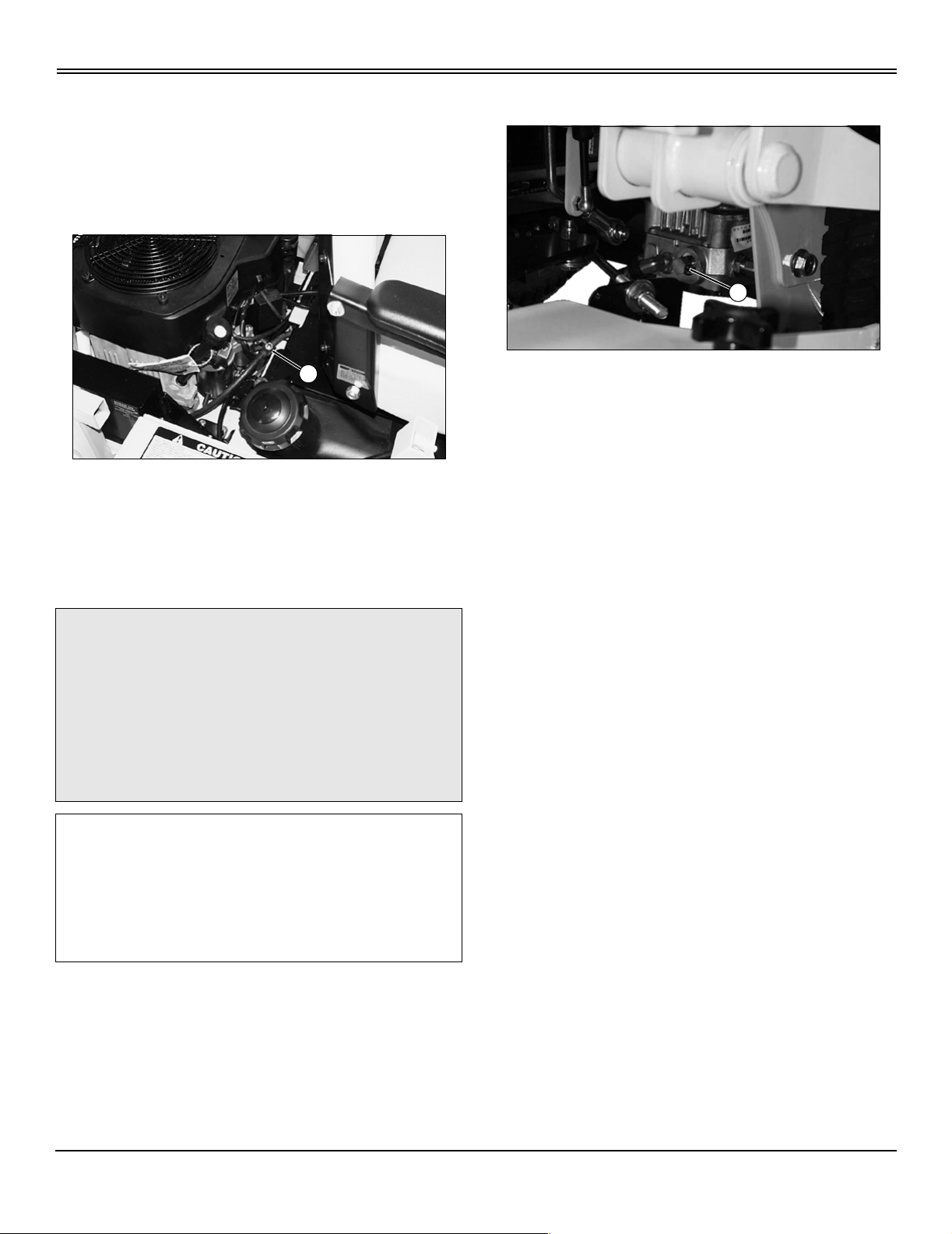
Changing Engine Oil and Filter
A
MX9413
NOTE: An oil drain tube is provided with your machine.
Attach the tube to the oil drain fitting on your engine,
and open the valve (A) to drain the used oil. Close the
valve, and remove the drain tube from the fitting after
the oil has been drained. Store the drain tube after use.
Change engine oil and filter at the intervals recommended
in the Service Intervals section. See the engine
manufacturer’s owner’s manual provided with your
machine for the complete procedure.
IMPORTANT: Avoid damage! Failure to check the oil
level regularly could lead to serious engine
problems if oil level is low:
• Check oil level before operating.
• Check oil level when the engine is cold and not
running.
• Keep level between the FULL and the ADD marks.
• Shut off engine before adding oil.
NOTE: Check oil twice a day if you run engine over 4
hours in a day.
Make sure engine is cold when checking engine oil
level.
1. Park machine safely. (See Parking Safely in the Safety
section.)
2. Clean area around dipstick to prevent debris from falling
into crankcase.
3. Remove dipstick. Wipe with a clean cloth.
4. Install and tighten dipstick.
5. Remove dipstick and check oil level on dipstick. Oil must
be between ADD and FULL marks. If oil is low, add oil to
bring oil level no higher than FULL mark on dipstick. Do not
Cleaning Air Intake Screen and Engine Fins
IMPORTANT: Avoid damage! The engine is aircooled and requires a large amount of air intake
when running. Reduced air intake can cause
overheating:
• Keep air intake screen and cooling fins clean.
• Keep covers and screens in place.
Keep air intake screens and engine cooling fins clear of
debris to ensure proper cooling. See the engine
manufacturer’s owner’s manual provided with your
machine for the complete procedure.
Checking and Cleaning Air Filter Elements
c CAUTION: Avoid injury! Touching hot surfaces
can burn skin. The engine and components will
be hot if the engine has been running. Allow
the engine to cool before servicing.
Service Engine - 13
Page 17

SERVICE ENGINE
IMPORTANT: Avoid damage! Dirt and debris can
enter the engine through a damaged filter element:
• Do not wash paper element.
• Do not attempt to clean paper element by tapping
against another object.
• Do not use pressurized air to clean element.
• Replace element only if it is very dirty, damaged
or the seal is cracked.
Check and clean air filter elements at the intervals
recommended in the Service Intervals section. See the
engine manufacturer’s owner’s manual provided with your
machine for the complete procedure.
Checking Spark Plug
c CAUTION: Avoid injury! Touching hot surfaces
can burn skin. The engine and components will
be hot if the engine has been running. Allow
the engine to cool before servicing.
Check spark plugs at the intervals recommended in the
Service Intervals section. See the engine manufacturer’s
owner’s manual provided with your machine for the
complete procedure.
Replacing Fuel Filter
c CAUTION: Avoid injury! Fuel vapors are
explosive and flammable:
• Do not smoke while handling fuel.
• Keep fuel away from flames or sparks.
• Shut off engine before servicing.
• Cool engine before servicing.
• Work in a well-ventilated area.
• Clean up spilled fuel immediately.
1. Park machine safely. (See Parking Safely in the Safety
section.)
2. Turn fuel shutoff valve to off position.
3. Disconnect the fuel hose from the outlet side of the fuel
filter, and drain gasoline into a properly marked container.
4. Remove the fuel filter from the inlet fuel hose. Discard
filter.
IMPORTANT: Avoid damage! When installing a new
fuel filter, the filter arrow must be pointing in the
direction of fuel flow.
5. Connect a new fuel filter to hoses.
6. Turn fuel shutoff valve to ON position.
Adjusting Carburetor
NOTE: Carburetor is calibrated by the engine
manufacturer and is not adjustable.
If engine is operated at altitudes above 1829 m (6,000
ft), some carburetors may require a special high
altitude main jet.
If engine is hard to start or runs rough, see the
troubleshooting section of the engine manufacturer’s
owner’s manual provided with your machine.
Possible engine surging will occur at high throttle with
transmission in “N” neutral and mower disengaged. This is
a normal condition due to the emission control system.
After performing the checks in the troubleshooting section
and your engine is still not performing correctly, contact the
local engine manufacturer’s authorized servicing dealer.
Service Engine - 14
Page 18

SERVICE TRANSMISSION
Service Transmission
Avoid Fumes
c CAUTION: Avoid injury! Engine exhaust fumes
contain carbon monoxide and can cause
serious illness or death.
Move the vehicle to an outside area before
running the engine.
Do not run an engine in an enclosed area
without adequate ventilation.
A
• Connect a pipe extension to the engine
exhaust pipe to direct the exhaust fumes out of
the area.
• Allow fresh outside air into the work area to
clear the exhaust fumes out.
Transmission Oil
Use only Quaker State® 5W-50 or Mobil-1® 15W-50 all
synthetic oil.
Checking Transmission Oil Level
1. Park machine safely. (See Parking Safely in the Safety
section.)
2. Remove the hydraulic reservoir cap. The oil level should
be 76 mm (3 in.) from the top of the filler pipe. Add oil as
needed.
Changing Transmission Oil and Filter
IMPORTANT: Avoid damage! Contamination of
hydraulic fluid could cause transmission damage or
failure. Do not open oil reservoir cap unless
absolutely necessary.
1. Park machine safely. (See Parking Safely in the Safety
section.)
2. Allow engine and hydraulic reservoir to cool.
3. Clean area around the reservoir filler cap, and remove
the filler cap from the reservoir.
MX9233
4. Turn hydraulic filter (A) counterclockwise to remove, and
drain oil into a properly marked container with a capacity of
at least 7.5 L (2.0 gal).
5. Apply a film of clean oil to gasket of new filter.
6. Install filter. Turn filter clockwise until gasket makes
contact with the mounting surface. Tighten 1/2 to 3/4 turn
after contact.
7. Fill reservoir with approximately 2.8 L (3 qt) (low-profile
tank) or 3.8 L (4 qt) (high-profile tank) of oil.
8. Install reservoir cap.
9. Bleed air from hydraulic system.
Adjusting Transmission Neutral Position
1. Park machine safely. (See Parking Safely in the Safety
section.)
c CAUTION: Avoid injury! Machine must be
safely supported on jackstands before
removing or installing wheels. Do not use a
hoist or floor jack to support the machine.
2. Raise drive wheel off the ground and securely support
the machine, and block caster wheels.
3. Start and run the engine until it reaches normal
operating temperature.
4. Observe wheel movement as control levers are moved
back and forth. The wheels should travel in the correct
direction as the levers are moved.
Service Transmission - 15
Page 19

SERVICE TRANSMISSION
A
MX9244
5. Move control levers to neutral position. The wheels
should stop rotating. If the wheels continue to rotate, adjust
the neutral adjustment knob(s) (A), located on each side of
the seat, until wheel(s) stop rotating.
B
B
A
MX9216
Picture Note: Drive belt routing as viewed from the
top of machine.
3. Disconnect tension spring (A) from the anchor pin.
4. Remove drive belt (B).
5. Install new drive belt (B).
6. Connect tension spring (A) to anchor pin.
7. Install mower deck drive belt.
MX9250
6. Adjust neutral switch activator bolt(s) (B) as needed.
The switches should be engaged when the control levers
are in the neutral position.
7. Shut engine off.
8. Lower the machine to the ground.
Removing and Installing Traction Drive Belt
1. Park machine safely. (See Parking Safely in the Safety
section.)
2. Remove mower deck drive belt.
Bleeding Hydraulic System
c CAUTION: Avoid injury! Escaping fluid under
pressure can penetrate the skin causing
serious injury. Avoid the hazard by relieving
pressure before disconnecting hydraulic or
other lines. Tighten all connections before
applying pressure. Search for leaks with a
piece of cardboard. Protect hands and body
from high pressure fluids.
Use caution when filling and draining hydraulic
oil. During periods of machine operation, the
hydraulic oil reservoir can get hot. Allow
engine and oil reservoir to cool before
servicing.
IMPORTANT: Avoid damage! Contamination of
hydraulic fluid could cause transmission damage or
failure. Do not open oil reservoir cap unless
absolutely necessary.
Severe or unusual conditions may require a more
frequent service interval.
NOTE: Whenever hydraulic components are removed
from the system, hoses are disconnected, or the
system has been drained, trapped air must be removed
from the hydraulic system.
Service Transmission - 16
Page 20

SERVICE TRANSMISSION
1. Park machine safely. (See Parking Safely in the Safety
section.)
2. Check hydraulic oil level. Adjust as necessary.
c CAUTION: Avoid injury! Machine must be
safely supported on jackstands before
removing or installing wheels. Do not use a
hoist or floor jack to support the machine.
3. Raise drive wheels off the ground and block caster
wheels.
NOTE: The pumps are located under the machine,
behind the mower deck.
A
MX9226
Picture Note: Left pump shown.
4. Open free-wheeling valves (A) one full turn
counterclockwise and start engine.
5. Slowly move the control levers in both forward and
reverse directions five to six times. As the air is purged
from the unit, the oil level will drop.
6. Turn off engine and check oil level. Adjust as necessary.
7. Close the free-wheeling valves and tighten to 9-14 N•m
(80-120 lb-in.).
8. Start engine and slowly move the control levers in both
forward and reverse directions five to six times.
9. Turn off engine and lower machine to ground. Check oil
level and adjust as necessary. Mower should move in
forward and reverse at normal speed, if not, repeat
procedure.
Service Transmission - 17
Page 21

SERVICE MOWER
Service Mower
Adjusting Mower Level
c CAUTION: Avoid injury! Mower blades are
sharp. Always wear gloves when handling
mower blades or working near blades.
1. Park machine safely. (See Parking Safely in the Safety
section.)
2. Inflate drive (rear) tires to 69-83 kPa (10-12 psi), and
caster (front) tires to 110-139 kPa (16-20 psi).
3. Adjust cutting height to 50 mm (2 in.), and lower mower
to cutting position.
D
C
B
A
• If no adjustment is required, proceed to Step 8.
H
G
I
J
MX9221
7. Loosen jam nuts (G) and (H) on the swivel adjuster rod.
Turn the jam nuts as required to obtain the desired height
of position D.
8. Measure the distance from the top of the mower deck to
the ground at positions C and D. The height at position C
must be 3-6 mm (1/8-1/4 in.) higher than position D.
• If adjustment is required, proceed to Step 9.
• If no adjustment is required, proceed to Adjust
Cutting Height.
MX9288
4. Measure the distance from the top of the mower deck to
the ground at positions A and B. The height at position A
must be 3-6 mm (1/8-1/4 in.) higher than position B.
• If adjustment is required, proceed to Step 5.
• If no adjustment is required, proceed to Step 6.
E
F
MX9284
5. Loosen jam nuts (E) and (F) on the swivel adjuster rod.
Turn the jam nuts as required to obtain the desired height
of position A.
6. Measure the distance from the top of the mower deck to
the ground at positions B and D. The heights of position B
and D should be equal, ±3 mm (1/8 in.).
• If adjustment is required, proceed to Step 7.
9. Loosen the nut (I), and slide cap screw (J) in the slot
until the desired height at position C is obtained. Tighten
the nut.
Adjust Cutting Height
1. Set the cutting height to 89 mm (3-1/2 in.), and lower
mower to cutting position.
A
MIF
2. Turn right blade (A) so that the blade tip is pointing out
of the middle of the discharge chute.
3. Measure from outside blade tip to flat ground surface. If
the blade height (A) is not 89 mm (3-1/2 in.), adjust the
cutting height.
Service Mower - 18
Page 22

SERVICE MOWER
B
C
MX9285
4. Loosen the jam nut (B) on the link rod assembly, and
turn the sleeve (C) until the blade height is 89 mm (3-1/2
in.). Tighten the jam nut.
Checking and Adjusting Mower Deck Drive Belt Tension
counterclockwise.
Removing and Installing Mower Deck Drive
Belts
1. Park machine safely. (See Parking Safely in the Safety
section.)
2. Raise foot platform.
3. Remove mower deck drive belt covers.
B
A
1. Park machine safely. (See Parking Safely in the Safety
section.)
2. Adjust the mower deck for the lowest cutting height, and
lower the deck.
A
C
B
D
MX9217
3. Check the mower deck drive (A) and spindle drive (B)
belt tension. The belts should deflect a maximum of 13 mm
(1/2 in.) when a force of 4.5 kg (10 lb) is applied to the
center of the longest span.
• To Increase Belt Tension: Turn nut (C - mower
deck drive belt) or (D - spindle drive belt) clockwise.
D
C
MX9217
4. Release mower deck drive belt tension, by turning the
tension adjuster nut (A) counterclockwise.
5. Remove mower deck drive belt (B).
6. Release spindle drive belt tension by turning tension
adjustment nut (C) counterclockwise.
7. Remove spindle drive belt (D).
8. Install new spindle drive belt (D) and adjust drive belt
tension.
9. Install new mower deck drive belt (B) and adjust drive
belt tension.
10.Install mower deck drive belt covers.
11.Lower foot platform.
• To Decrease Belt Tension: Turn nut (C - mower
deck drive belt) or (D - spindle drive belt)
Service Mower - 19
Page 23

SERVICE MOWER
Checking for Bent Mower Blades
c CAUTION: Avoid injury! Mower blades are
sharp. Always wear gloves when handling
mower blades or working near blades.
1. Park machine safely. (See Parking Safely in the Safety
section.)
2. Lower mower deck to mowing position.
A
MIF
3. Measure distance (A) between blade tip and flat ground
surface.
4. Turn blade 180°. Measure distance between the other
blade tip and flat ground surface.
A
C
B
D
MX9231
2. Remove nut (A), blade (B), blade washers (C), and bolt
(D).
3. Install blade (B), blade washers (C), bolt (D) and secure
using nut (A). Tighten nut to 80 N•m (60 lb-ft).
Balancing Mower Blades
1. Clean blade.
5. Install a new blade if the difference between the two
measurements is more than 3 mm (1/8 in.).
Servicing Mower Blades
c CAUTION: Avoid injury! Mower blades are
sharp. Always wear gloves when handling
mower blades or working near blades.
Removing and Installing Mower Blades
1. Park machine safely. (See Parking Safely in the Safety
section.)
M61524
2. Put blade on nail in a vise. Turn blade to horizontal
position.
3. Check balance. If blade is not balanced, heavy end of
blade will drop.
4. Grind bevel of heavy end. Do not change blade bevel.
Sharpening Blades
c CAUTION: Avoid injury! Always wear safety
eye protection when grinding.
• Sharpen blades with grinder, hand file, or electric blade
sharpener.
Service Mower - 20
Page 24

SERVICE MOWER
A
B
M61830
• Keep original bevel (A) when grinding.
• Blade should have 0.40 mm (1/64 in.) cutting edge (B)
or less.
• Balance blades before installing.
Replacing Mower Spindle Bearings
1. Park machine safely. (See Parking Safely in the Safety
section.)
2. Remove mower deck drive and spindle drive belt.
A
B
C
K
J
I
D
E
F
3. Remove mower blade.
H
G
MX9222A
4. Remove upper pulleys:
• Side Spindles: Remove nut (A), spacer (B) and
pulley (C).
• Center Spindle: Remove nut (D), drive pulley (E)
and spindle pulley (F).
5. Remove spindle shaft (G), lower bearing (H) and spacer
(I) from spindle housing (J). Discard bearing.
6. Remove and discard upper bearing (K).
7. Clean entire assembly.
8. Install a new lower bearing (H) and spacer (I) on the
spindle shaft (G).
IMPORTANT: Avoid damage! The clearance between
the lower bearing and the housing is only 0.05 mm
(0.002 in.). Do not force bearing into housing.
9. Install the spindle shaft (G), lower bearing (H) and
spacer (I) into the spindle housing (J).
10.Install the upper bearing (K).
Service Mower - 21
Page 25

SERVICE MOWER
11.Install upper pulleys:
• Side Spindles: Install pulley (C), spacer (B) and nut
(A). Tighten nut to 80 N•m (60 lb-ft).
• Center Spindle: Install spindle pulley (F), drive
pulley (E) and nut (D). Tighten nut to 80 N•m (60 lb-ft).
12.Install mower blade. Tighten nut to 80 N•m (60 lb-ft).
Replacing Mower Deck Idler Pulleys
1. Park machine safely. (See Parking Safely in the Safety
section.)
2. Remove the mower deck drive and spindle drive belts.
A
B
D
C
MX9252
3. Remove mower deck drive tension idler pulleys (A) and
(B), mower deck drive fixed idler pulley (C) and spindle
drive tension idler pulley (D).
4. Install new idler pulleys.
5. Install spindle drive and mower deck drive belts.
6. Adjust belt tension.
Service Mower - 22
Page 26

SERVICE ELECTRICAL
Service Electrical
WARNING: Battery posts, terminals and related
accessories contain lead and lead components, chemicals
known to the State of California to cause cancer and
reproductive harm. Wash hands after handling.
Removing and Installing the Battery
c CAUTION: Avoid injury! The battery produces a
flammable and explosive gas. The battery may
explode:
• Do not smoke near battery.
• Wear eye protection and gloves.
• Do not allow direct metal contact across
battery posts.
• Remove negative cable first when
disconnecting.
• Install negative cable last when connecting.
Removing:
1. Park the vehicle safely. (See Parking Safely in the
safety section.)
C
D
A
B
F
battery tray.
3. Tighten the cap screws and nuts (E) to secure the
battery in the battery tray. Do not overtighten.
4. Connect the positive (+) battery cable (D) first, then the
negative (-) cable (B).
5. Apply general purpose grease or silicone spray to the
terminals to prevent corrosion.
6. Slide covers (A and C) over battery terminals.
Checking Battery Electrolyte Level
c CAUTION: Avoid injury! Battery electrolyte
contains sulfuric acid. It is poisonous and can
cause serious burns:
• Wear eye protection and gloves.
• Keep skin protected.
• If electrolyte is swallowed, get medical
attention immediately.
• If electrolyte is splashed into eyes, flush
immediately with water for 15-30 minutes and
get medical attention.
• If electrolyte is splashed onto skin, flush
immediately with water and get medical
attention if necessary.
NOTE: Add only distilled water to replace normal
electrolyte loss.
1. Park the vehicle safely. (See Parking Safely in the
safety section.)
2. Remove battery from vehicle and set it on a level
surface.
E
G
MX9209
2. Slide black cover (A) away from the negative (-) battery
terminal and disconnect the negative (-) battery cable (B).
3. Slide red cover (C) away from the positive (+) battery
terminal and disconnect the positive (+) battery cable (D).
4. Loosen the cap screws and nuts (E) on both sides of the
battery tray.
5. Remove battery (F) and isolator pad (G).
Installing:
1. Place isolator pad (G) in the battery tray.
2. Install battery (F) in the battery tray, making sure that
the isolator pad (G) is between the bottom and sides of the
Service Electrical - 23
3. Remove battery cell caps. Make sure cap vents are not
plugged.
B
A
C
MIF
4. Check electrolyte level. Electrolyte (A) should be
Page 27

SERVICE ELECTRICAL
approximately halfway between bottom of filler neck (B)
and top of plates (C).
IMPORTANT: Avoid damage! Do not overfill battery.
Electrolyte can overflow when battery is charged
and cause damage.
5. Add only distilled water if necessary.
6. Install battery cell caps.
7. Install battery.
Cleaning Battery and Terminals
c CAUTION: Avoid injury! The battery produces a
flammable and explosive gas. The battery may
explode:
• Do not smoke near battery.
• Wear eye protection and gloves.
• Do not allow direct metal contact across
battery posts.
• Remove negative cable first when
disconnecting.
• Install negative cable last when connecting.
1. Disconnect and remove battery.
2. Wash battery with a solution of four tablespoons of
baking soda to one gallon of water. Be careful not to get the
soda solution into the battery cells.
3. Rinse the battery with plain water and dry.
4. Clean terminals and battery cable ends with wire brush
until bright.
5. Install battery.
6. Attach cable clamps to battery posts.
7. Apply petroleum jelly or silicone spray to terminal to
prevent corrosion.
Replacing Fuses
IMPORTANT: Avoid damage! When replacing fuses use only 20-amp fuses or you may damage the
circuit.
A
B
MX9245
1. Remove defective fuse (A - electric start circuit) or (B charging circuit) from socket.
2. Check metal clip in fuse window and discard fuse if clip
is broken.
3. Install new fuse into socket.
Check and Adjust PTO Clutch Air Gap
NOTE: If clutch is not equipped with adjusting nuts (B),
no adjustment is required.
1. Park the vehicle safely. (See Parking Safely in the
safety section.)
B
A
2. Check the air gap at the three openings (A) around the
clutch, using a feeler gauge. The air gap should be within
0.012-0.584 mm (0.005-0.023 in.). If the gap is not within
specifications, adjust the air gap.
3. Adjust the air gap to 0.34 mm (0.12 in.), by tightening or
loosening the three adjustment nuts (B).
B
MX9290
Two 20-amp fuses to protect the electric start and charging
circuit are located behind the seat area.
Service Electrical - 24
Page 28

Kohler Wiring Schematic
SERVICE ELECTRICAL
MX9299A
Service Electrical - 25
Page 29

SERVICE MISCELLANEOUS
Service Miscellaneous
Filling Fuel Tank
Use regular grade 87 octane unleaded fuel.
Add fuel stabilizer to fuel before using it in your machine to
prevent engine damage due to stale fuel. Follow directions
on stabilizer container.
c CAUTION: Avoid injury! Fuel vapors are
explosive and flammable:
• Shut engine off before filling fuel tank.
• Do not smoke while handling fuel.
• Keep fuel away from flames or sparks.
A
B
C
E
F
• Fill fuel tank outdoors or in well-ventilated
area.
• Clean up spilled fuel immediately.
• Use clean, approved non-metal container to
prevent static electric discharge.
• Use clean, approved plastic funnel without
screen or filter to prevent static electric
discharge.
IMPORTANT: Avoid damage! Dirt and water in fuel
can cause engine damage:
• Clean dirt and debris from the fuel tank opening.
• Use clean, fresh, stabilized fuel.
• Fill the fuel tank at the end of each day’s
operation to keep condensation out of the fuel tank.
• Use a non-metallic funnel with a plastic mesh
strainer when filling the fuel tank or container.
Checking Wheel Nuts
Tighten rear wheel nuts in an alternating pattern to 68 N•m
(50 lb-ft.).
G
F
E
C
D
MX9223
3. Remove lock nut (A), bolt (B), two spacers (C) and
wheel assembly (D).
4. Remove seals (E), bearings (F) and spacer tube (G)
from wheel.
5. Clean and inspect bearings (F) and pack with clean
grease. Replace bearings as needed.
6. Install spacer tube (G), bearings (F) and new seals (E).
7. Install wheel assembly (D), two spacers (C), bolt (B) and
lock nut (A).
Servicing Caster Pivot Bearings
1. Park machine safely. (See Parking Safely in the Safety
section.)
2. Raise and securely support the front of the mower deck.
Servicing Caster Wheel Roller Bearings
1. Park machine safely. (See Parking Safely in the Safety
section.)
2. Raise and securely support the front of the mower deck.
Service Miscellaneous - 26
Page 30

SERVICE MISCELLANEOUS
A
B
C
J
F
L
G
I
H
E
D
MX9224
3. Remove cap (A), cotter pin (B), castle nut (C), caster
yoke and wheel assembly (D) and caster bushing (E).
NOTE: It is not necessary to remove the bearing races
(F) and (G), unless the bearings need to be replaced.
4. Remove seal (H) and lower bearing (I).
5. Remove upper bearing (J).
6. Clean and inspect bearings (I) and (J); pack with clean
grease. Replace bearings if needed.
7. Install lower bearing (I) and a new seal (H).
8. Install upper bearing (J).
NOTE: Do not overtighten castle nut (C). Tighten castle
nut only enough to remove excess play from bearings.
Align crossdrill and nut to allow installation of the
cotter pin (B). The caster wheel yoke assembly must be
free to rotate.
9. Install caster bushing (E) on yoke shaft, and install
caster yoke and wheel assembly (D), castle nut (C), and
cotter pin (B).
10.Apply grease to lubrication fitting (L) until you can see
grease at the top bearing (J). Install grease cap (A).
Service Miscellaneous - 27
Page 31

TROUBLESHOOTING
Troubleshooting
Using Troubleshooting Chart
If you are experiencing a problem that is not listed in this
chart, see your Great Dane dealer for service.
When you have checked all the possible causes listed and
you are still experiencing the problem, see your Great
Dane dealer.
Engine
NOTE: This engine troubleshooting chart covers items
that are unique to the machine operation. See the
engine manufacturer’s owner’s manual provided with
your machine for detailed engine troubleshooting
procedures.
If Check
Poor Engine Performance Dirt in fuel system or fuel is old; obtain fresh fuel from another
supplier before suspecting machine problems. Suppliers blend fuels
differently and changing suppliers will generally solve any
performance problems.
Fuel blended with alcohol or ether may contribute to performance
problems by causing gum and varnish deposits, especially if fuel is
stored for several weeks or more. Obtain fresh fuel.
Engine Will Not Start Park brake not locked.
Control levers are not in neutral position.
PTO/clutch switch is in on position.
Fuel shutoff valve in off position.
Spark plug wire(s) loose or disconnected.
Improper fuel.
Plugged fuel filter.
Electrical problem. (See Electrical Troubleshooting section)
Engine Will Not Idle Operator rising off the seat.
Engine Stops Or Misses When Operating On
Hillsides
Engine Backfires Operator rising off of the seat.
Fuel tank less than half full of fuel.
Operator rising off of the seat.
Troubleshooting - 28
Page 32

TROUBLESHOOTING
Electrical
If Check
Starter Does Not Work Or Will Not Turn Engine Park brake is not locked.
PTO/clutch switch is in on position.
Battery terminals are corroded.
Battery not charged.
20-amp fuse is blown.
Battery Will Not Charge Dead cell in the battery.
Battery cables and terminals are dirty.
Low engine speed or excessive idling.
Machine Operation
If Check
Machine Vibrates Too Much Or Rattles Excessively Attachment drive belts worn or damaged.
Traction drive belt damaged or worn.
Dirt on drive sheaves.
Machine Will Not Move With Engine Running Park brake locked.
Transmission hydraulic oil level low.
Free-wheeling valves are open.
Traction drive belt damaged or worn.
Machine Will Not Follow a Straight Path Steering tracking out of adjustment.
Machine Moves To The Left Or Right With Engine
Running And Transmission In Neutral
Pump linkage (neutral position) out of adjustment.
Mower
If Check
Discharge Chute Plugged Travel speed too fast.
Grass too long.
Grass too wet.
Engine rpm not at wide open throttle.
Restricted air flow.
Belt installed incorrectly.
Patches Of Grass Uncut Travel speed too fast.
Engine rpm not at wide open throttle.
Mower deck needs cleaning.
Troubleshooting - 29
Page 33

TROUBLESHOOTING
If Check
Belt Slipping Debris in sheaves.
Worn belt.
Too Much Vibration Debris on mower deck or in sheaves.
Damaged sheaves or sheaves out of alignment.
Damaged drive belt.
Blades out of balance.
Blades Scalping Grass Cutting too low.
Mower wheels not adjusted correctly.
Turning speed too fast.
Ridges in terrain.
Rough or uneven terrain.
Low tire pressure.
Mower Loads Down Engine Engine rpm too low.
Travel speed too fast.
Debris wrapped around mower spindles.
Uneven Cut Mower deck not leveled properly.
Travel speed too fast.
Blades dull.
Mower wheels not adjusted correctly.
Tire pressure unequal.
Grass Tips Are Jagged And Turn Grayish Brown
After Mowing
Dull mower blades.
Mower deck not leveled properly.
Troubleshooting - 30
Page 34

STORAGE
Storage
Storing Safety
c CAUTION: Avoid injury! Fuel vapors are
explosive and flammable. Engine exhaust
fumes contain carbon monoxide and can cause
serious illness or death:
• Run the engine only long enough to move
the machine to or from storage.
• Do not store vehicle with fuel in the tank
inside a building where fumes may reach an
open flame or spark.
• Allow the engine to cool before storing the
machine in any enclosure.
Preparing Machine for Storage
1. Repair any worn or damaged parts. Replace parts if
necessary. Tighten loose hardware.
2. Repair scratched or chipped metal surfaces to prevent
rust.
3. Clean under the deck and remove grass and debris
from inside chute and bagger.
4. Wash the machine and apply wax to metal and plastic
surfaces.
5. Run machine for five minutes to dry belts and pulleys.
6. Apply light coat of engine oil to pivot and wear points to
prevent rust.
circulate through carburetor.
Engine:
Engine storage procedure should be used when vehicle is
not to be used for longer than 60 days.
1. Change engine oil and filter while engine is warm.
2. Service air filter if necessary.
3. Clean debris from engine air intake screen.
4. Remove spark plugs. Put 30 mL (1 oz.) of clean engine
oil in cylinders.
5. Crank the engine five or six times to allow oil to be
distributed.
6. Install spark plugs.
7. Clean the engine and engine compartment.
8. Remove battery.
9. Clean the battery and battery posts. Check the
electrolyte level.
10.Move fuel shut-off valve to off position.
11.Store the battery in a cool, dry place where it will not
freeze.
NOTE: The stored battery should be recharged every
90 days.
12.Charge the battery.
13.Store the vehicle in a dry, protected place. If vehicle is
stored outside, put a waterproof cover over it.
Preparing Fuel and Engine for Storage
Fuel:
If you have been using “Stabilized Fuel”, add stabilized fuel
to tank until the tank is full.
NOTE: Filling the fuel tank reduces the amount of air in
the fuel tank and helps reduce deterioration of fuel.
If you are not using “Stabilized Fuel”:
1. Park machine safely in a well-ventilated area.
NOTE: Try to anticipate the last time the machine will
be used for the season so very little fuel is left in the
fuel tank.
2. Turn on engine and allow to run until it runs out of fuel.
3. Turn key to off position.
4. Mix fresh fuel and fuel stabilizer in separate container.
Follow stabilizer instructions for mixing.
5. Fill fuel tank with stabilized fuel.
6. Run engine for a few minutes to allow fuel mixture to
Removing Machine From Storage
1. Check tire pressure.
2. Check engine oil level.
3. Check battery electrolyte level. Charge battery if
necessary.
4. Install battery.
5. Check spark plug gap. Install and tighten plugs to
specified torque.
6. Lubricate all grease points.
7. Turn fuel shut-off valve to on position.
8. Run the engine 5 minutes without the mower or any
attachments running to allow oil to be distributed
throughout engine.
9. Be sure all shields and guards or deflectors are in place.
Storage - 31
Page 35

ASSEMBLY
Assembly
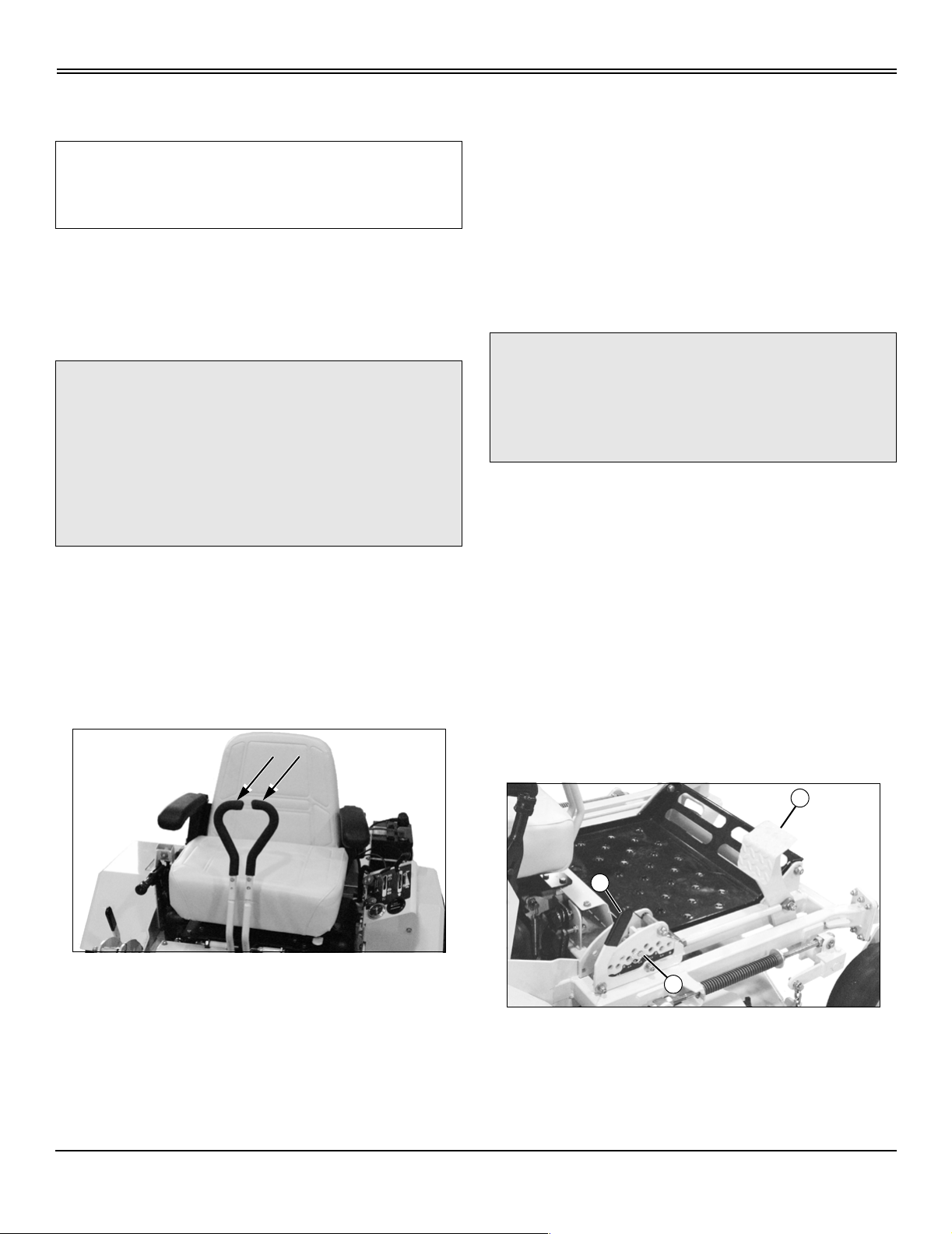
Install Seat and Control Lever Handles
1. Install seat on platform and secure using nuts provided
in small parts bag.
2. Connect seat safety switch to wiring harness.
3. Install handles on control levers and secure using
sleeves, cap screws and nuts provided in small parts bag.
Activate and Charge Battery
c CAUTION: Avoid injury! Battery electrolyte
contains sulfuric acid. It is poisonous and can
cause serious burns:
• Wear eye protection and gloves.
• Keep skin protected.
• If electrolyte is swallowed, get medical
attention immediately.
• If electrolyte is splashed into eyes, flush
immediately with water for 15-30 minutes and
get medical attention.
• If electrolyte is splashed onto skin, flush
immediately with water and get medical
attention if necessary.
1. Park the vehicle safely. (See Parking Safely in the
Safety section.)
2. Remove battery from machine and set it on a level
surface.
3. Remove battery cell caps. Make sure cap vents are not
plugged.
be 6 mm (1/4 in.) above plates (B), but NO HIGHER
than 6 mm (1/4 in.) from the bottom of the filler neck (C).
5. Install the battery caps before charging the battery.
IMPORTANT: Avoid damage! Wait 20 minutes before
charging the battery to allow the plates to “absorb”
the acid, so they will take a charge well.
Battery must be charged before operation. Adding
acid without charging will result in battery damage.
6. Charge the battery for a minimum of 30 minutes at 5-10
amps. If your battery charger has a Deep Cycle or
Maintenance Free setting, use this setting to charge the
battery. Failure to charge the battery before use will reduce
battery performance and life.
7. Install the battery in the machine.
Check Fluid Levels
IMPORTANT: Avoid damage! Check all fluid levels
before attempting to start the machine. Machine
should be parked on a hard, level surface with the
key switch in the STOP position.
Check Engine Oil Level
Oil level should be between the ADD and FULL marks on
the dipstick. Add oil as necessary.
Check Transmission Oil Level
Hydraulic oil level should be to the top of the FULL COLD
mark on the reservoir dipstick. Add oil as necessary.
If your mower has no dipstick, make sure that oil is 76 mm
(3 in.) from the top of the filler pipe.
C
A
B
4. Fill the battery:
• Only use battery acid with a 1.265 specific gravity.
• Slowly add acid (A) to each cell. The solution should
Lubricate Machine
Lubricate all moving parts before operating the machine,
see Lubrication Points in Service Lubrication section.
Check Safety System
For a complete checkout procedure of the safety interlock
system, see Testing the Safety Interlock System in the
Operating section.
MIF
Assembly - 32
Page 36

ASSEMBLY
Check Tire Pressure
c CAUTION: Avoid injury! Explosive separation
of tire and rim parts is possible when they are
serviced incorrectly:
• Do not inflate the tires above the
recommended pressure.
• Do not stand in front or over the tire
assembly when inflating. Use a clip-on chuck
and extension hose long enough to allow you
to stand to one side.
1. Check tires for damage.
2. Check tire pressure with an accurate gauge.
3. Check that tires have equal pressure; add or remove air,
if necessary.
Tire Size Pressure
Front: 13 x 5.0 - 6 110-139 kPa (16-20 psi)
Rear: 23 x 9.5- 12 69-83 kPa (10-12 psi)
c CAUTION: Avoid injury! Engine exhaust fumes
contain carbon monoxide and can cause
serious illness or death.
Move the vehicle to an outside area before
running the engine.
Do not run an engine in an enclosed area
without adequate ventilation.
• Connect a pipe extension to the engine
exhaust pipe to direct the exhaust fumes out of
the area.
• Allow fresh outside air into the work area to
clear the exhaust fumes out.
3. Start and run the engine until it reaches normal
operating temperature.
4. Move control levers to the forward position and observe
drive wheel rotation; the drive wheels should rotate in the
correct direction.
5. Move the control levers to the reverse position and
observe drive wheel rotation; the drive wheels should
rotate in the correct direction.
Level Mower Deck
Before operating the machine, level the mower deck.
Initial Adjustments
c CAUTION: Avoid injury! Clear area of
bystanders before performing this service
procedure.
1. Check free-wheeling valves on both pump assemblies
to make sure that the valves are closed.
2. Raise the rear of the machine until the drive wheels are
off the ground. Support the machine with jackstands.
NOTE: Neutral position and transmission linkage
adjustments will needed to be recheck after several
hours of operation.
6. Release control levers; the levers should return to the
neutral position and wheel rotation should stop. If the
wheels do not stop, adjust the neutral adjustment knob on
each side of the seat.
7. Move PTO/clutch switch to on position; mower clutch
should engage. Run blades for several minutes.
8. Move PTO/clutch switch to off position and shut the
engine off.
9. Check all belts for proper tension.
10.Start the engine and test drive the machine in an open
area. Drive the machine forward; if the machine drifts to the
right or left, adjust the transmission control linkage.
PTO Clutch Run-in Procedure
1. Start and run the engine at half throttle.
2. Engage and disengage the PTO clutch five times (ten
seconds on, ten seconds off).
3. Move throttle lever to 3/4 throttle.
4. Engage and disengage the PTO clutch five times (ten
seconds on, ten seconds off).
Assembly - 33
Page 37

SPECIFICATIONS
Specifications
Engine
NOTE: See engine manufacturer’s owner’s manual
provided with your machine for engine specifications.
Battery
Voltage . . . . . . . . . . . . . . . . . . . . . . . . . . . . . . . . . . . 12 volt
CCA . . . . . . . . . . . . . . . . . . . . . . . . . . . . . . . 235 amp @ 0°
Reserve Capacity . . . . . . . . . . . . . . . . . . . . . . . .25 minutes
BCI Group Size. . . . . . . . . . . . . . . . . . . . . . . . . . . . . . . . U1
Tires
Front . . . . . . . . . . . . . . . . . . . . . . . . . . . . . . . . . 13 x 5.0 - 6
Rear . . . . . . . . . . . . . . . . . . . . . . . . . . . . . . . 23 x 9.50 - 12
Inflation Front . . . . . . . . . . . . . . . . 110-139 kPa (16-20 psi)
Inflation Rear . . . . . . . . . . . . . . . . . . 69-83 kPa (10-12 psi)
Wheel Nut Torque. . . . . . . . . . . . . . . . . . . 68 N•m (50 lb-ft)
Capacities
Fuel Tank . . . . . . . . . . . . . . . . . . . . . . . . . . . . 30.2 L (8 gal)
Hydraulic System
Low-Profile Tank . . . . . . . . . . . . . . . . . . . . . . . 4.3 L (4.5 qt)
High-Profile Tank . . . . . . . . . . . . . . . . . . . . . . 5.2 L (5.5 qt)
Dimensions
Wheel Base . . . . . . . . . . . . . . . . . . . . . . . . . 1,27 m (50 in.)
Overall Height . . . . . . . . . . . . . . . . . . . . . . . 1,11 m (44 in.)
Overall Length (All Models) . . . . . . . . . . . . . 1,98 m (78 in.)
Overall Width (with 52-Inch Mower Deck) . . 1,57 m (62 in.)
Overall Width (with 61-Inch Mower Deck) . . 1,80 m (71 in.)
52-Inch Mower Deck
Mower Type . . . . . . . . . . . . . . . . . . . . . . . . Side Discharge
Cutting Blades . . . . . . . . . . . . . . . . . . . . . . . . . . . . . . . . . .3
Blade Bolt Torque . . . . . . . . . . . . . . . . . . .80 N•m (60 lb-ft)
Cutting Width . . . . . . . . . . . . . . . . . . . . . . . . 1,32 m (52 in.)
Cutting Height (approximate) . . . 25 to 152 mm (1 to 6-in.)
Height Adjustment . . . . . . . . . . 13 mm (1/2 in.) increments
61-Inch Mower Deck
Mower Type . . . . . . . . . . . . . . . . . . . . . . . . Side Discharge
Cutting Blades . . . . . . . . . . . . . . . . . . . . . . . . . . . . . . . . . .3
Blade Bolt Torque . . . . . . . . . . . . . . . . . . .80 N•m (60 lb-ft)
Cutting Width . . . . . . . . . . . . . . . . . . . . . . . . 1,55 m (61 in.)
Cutting Height (approximate) . . . . 25 to 152 mm (1 to 6 in.)
Height Adjustment . . . . . . . . . . 13 mm (1/2 in.) increments
Hydraulic Oil Reservoir
Low-Profile Tank . . . . . . . . . . . . . . . . . . . . . . . . 2.8 L (3 qt)
High-Profile Tank . . . . . . . . . . . . . . . . . . . . . . . 3.8 L (4 qt)
Net Weight (With Mower Deck and Without Fuel)
23-hp Kawasaki engine/52 in. deck . . . . . 510 kg (1125 lb)
25-hp Kohler engine/52 in. deck . . . . . . . . 533 kg (1175 lb)
23-hp Kawasaki engine/61 in. deck . . . . . 535 kg (1180 lb)
25-hp Kawasaki engine/61 in. deck . . . . . 535 kg (1180 lb)
25-hp Kohler engine/61 in. deck . . . . . . . . 535 kg (1181 lb)
26-hp Kohler engine/61 in. deck . . . . . . . . 544 kg (1200 lb)
Travel Speeds
Forward. . . . . . . . . . . . . . . . . . . . . . . 0-16 km/h (0-10 mph)
Reverse . . . . . . . . . . . . . . . . . . . . . . . . 0-8 km/h (0-5 mph)
(Specifications and design subject to change without
notice.)
Specifications - 34
Page 38

INDEX
Index
A
Air Cleaner Elements, Replacing ................................... 13
Air Cleaner Elements, Servicing
..................................... 13
B
Battery and Terminals, Cleaning .................................... 24
Battery, Removing and Installing
Belt, Replacing Mower Drive (Primary)
Blades, Checking Mower
Blades, Servicing Mower
Brake, Using Park
................................................ 20
................................................ 20
............................................................ 7
.................................... 23
.......................... 19
C
Carburetor, Adjusting ..................................................... 14
Chart, Service Interval
Cleaning Air Intake Screen
.................................................... 11
............................................. 13
D
Daily Operating Checklist ................................................. 6
E
Engine Oil Level, Checking ............................................ 13
Engine and Fuel Storage, Preparing
Engine, Starting
Engine, Troubleshooting
................................................................ 7
................................................ 28
.............................. 31
Parts, Replacement
Plug, Checking Spark
........................................................10
.....................................................14
S
Safety Systems, Testing ................................................... 6
Safety, Tire
Service Interval Chart
Service Record
Spark Plug, Checking
Specifications
Storage, Preparing Fuel and Engine for
Storage, Preparing Machine for
Storage, Removing Machine from
Storing Safety
........................................................................5
.....................................................11
............................................................... 36
.....................................................14
..................................................................34
.........................31
......................................31
..................................31
.................................................................31
T
Testing Safety Systems ....................................................6
Tire Pressure, Check
Transmission Oil
Transmission Oil Level, Checking
Transmission Oil, Changing
...................................................... 33
.............................................................15
...................................15
............................................15
F
Filter, Changing Engine .................................................. 13
Filter, Changing Transmission
Fuel Safety
Fuel Storage
Fuel Tank, Filling
....................................................................... 5
................................................................... 31
............................................................ 26
........................................ 15
G
Grease ............................................................................ 12
L
Leveling Mower Side-to-Side ......................................... 18
M
Mower Blades, Checking ................................................ 20
Mower Blades, Servicing
Mower Drive (Primary) Belt, Replacing
Mower Level (Side-to-Side), Adjusting
................................................ 20
.......................... 19
........................... 18
O
Oil Level, Checking Engine ............................................ 13
Oil Level, Checking Transmission
Oil, Changing Engine
Oil, Transmission
Operating Checklist, Daily
..................................................... 13
............................................................ 15
................................................ 6
.................................. 15
P
Park Brake, Using ............................................................ 7
Part Numbers, Replacement
.......................................... 10
Index - 35
Page 39

NOTES
Notes
Notes
Page 40

Service Record GD
Record Service Dates
SERVICE RECORD GD
Engine Oil and
Filter Change
Lubricate
Machine
Air Cleaner Element
Clean/Replace
Service Record GD - 37
 Loading...