

795-90914 0812
Operation and Maintenance
Instructions
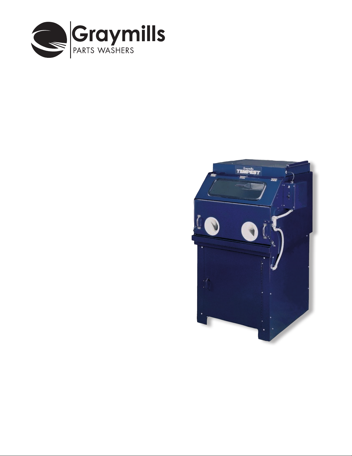
Tempest™ Jet Spray Cabinet
T-10, T-10S and T-20S

SAFETY WARNINGS
You will find various types of safety information on the following pages
and on the labels attached to Graymills equipment. The following
Safety Statements explain their meaning:
This is the safety alert symbol. It is used to alert you to potential
personal injury hazards. Obey all safety messages that follow
this symbol to avoid possible injury or death.
DANGER indicates a hazardous situation
which, if not avoided, will result in death or
serious injury.
WARNING indicates a hazardous situation
which, if not avoided, could result in death or
serious injury.
CAUTION, used with the safety alert symbol,
indicates a hazardous situation which, if not
avoided, could result in minor or moderate
injury.
CAUTION, used without the safety alert symbol,
is used to address practices not related to
personal injury.
The NOTE symbol means that failure to follow
these instructions could cause damage to the
equipment or cause it to operate improperly.
Reference Figures are located on Page 5.
Never work with equipment you feel may be unsafe. Contact
your Supervisor immediately if you feel a piece of equipment is
in an unsafe condition.
NEVER USE A FLAMMABLE OR COMBUSTIBLE FLUID IN THE
TEMPEST. USE ONLY NONFLAMMABLE, NON-COMBUSTIBLE,
WATER-BASED, LOW FOAMING CLEANING COMPOUNDS IN
THIS MACHINE.
DO NOT CONTAMINATE CLEANING FLUID WITH ANY
FLAMMABLE OR COMBUSTIBLE MATERIAL SUCH AS GASOLINE,
ALCOHOL, MINERAL SPIRITS, ETC. DRAIN PARTS TO BE
CLEANED OF ANY FLAMMABLE MATERIAL OR COMBUSTIBLE
MATERIAL BEFORE PLACING INSIDE CLEANING TANK. EVEN
SMALL QUANTITIES CAN CREATE A DANGEROUS FIRE
HAZARD.
Unit must be properly grounded to prevent electric shock hazard.
Connect only to three prong outlet. Should plug or cord become
cracked, frayed, damaged in any way, it should be repaired/replaced
immediately by a qualified electrician.
Never use an extension cord.
Since operator safety is at all times a priority, this unit is equipped
with a Ground Fault Interrupter (GFI). Should plug or cord require
replacement, it should be wired by a licensed electrician to the GFI in
the control box.
All electrical connections should conform to national/local codes and
be made by qualified personnel.
Before performing any maintenance on this unit, be sure to disconnect
electric power.
Prior to changing cleaning fluid or servicing the Tempest, make sure
that all moving parts have stopped and that heating element and
cleaning solution have cooled.
Pump operation is controlled by depressing an air switch foot pedal.
For safety, if this must be replaced, use only the same air switch, not an
electrically operated one.
Keep pump and motor clean and free of all contaminates. Never allow
any liquids to come into contact with motor or electrical systems as an
electric shock hazard could result.
Thermostat and pressure parameters have been factory set and must
never be tampered with.
• The Tempest 10, 10S and 20S Units are preset to operate up to
600 PSI. Operating with pressure greater than 600 PSI can create a
HAZARDOUS situation.
• Tempestisequippedwithapressurereliefvalveinthespraycabinet
(Figure 6). When pressure is relieved, the valve automatically resets.
Should pressure inside spray delivery system reach an unsafe level,
relief valve will vent excess pressure back into cabinet. This valve
must be kept clean and free of all contaminants to insure its proper
functioning. Activation of the pressure relief valve is not expected
during normal operation.
Do NOT start spray pump unless you have a firm grip on the nozzle. If
nozzle is dropped, stop pump immediately. An unrestrained hose and
nozzle could cause injury, damage to cabinet and parts in it, as well as
break the window, causing possible injury. Restrain parts which might
be violently moved by high pressure spray.
NEVER aim spray directly at gloves or anything other than parts to be
cleaned.
Always wear appropriate safety items such as gloves, apron, safety
glasses or goggles when loading, using or unloading or cleaning the
Tempest.
Follow all directions, Warnings and Cautions that are in the Material
Safety Data Sheet (MSDS) for the cleaning detergent being used.
In an accident where any cleaning solutions are splashed on clothing
follow MSDS. Remove wet clothing promptly and thoroughly wash
body areas that have been in contact with the solution. Do NOT permit
saturated clothing to remain in contact with skin. Industrial cleaners can
cause irritation to some individuals.
Cleaning solutions may irritate skin and eyes. If splashed in eyes, flush
thoroughly with water. Consult Material Safety Data Sheet (MSDS) and
a physician.
• Ifyouhaveanyquestionsregardingthecorrectcleaninguids
to use in this unit, call Graymills at 773-248-6825 and ask for
Customer Service. We recommend our low foaming Aquatene
2
™.
Tempest is equipped with a safety interlock switch that prevents the
pump from operating unless the cabinet door is closed and secured
with door hasps. Never override safety interlock switch or operate this
unit if the safety interlock switch is not functional.
Never open cabinet door when spray pump is operating, or try to
override the safety switch. If switch fails, do NOT use Tempest until
replaced.
Do NOT overload unit. Maximum capacity is 500 pounds.
Be careful to avoid hot areas within the cleaning chamber when
opening unit.
Parts will be heated during cleaning. Wear appropriate clothing and
protection.
Never operate unit with a cleaning solution reservoir level below
minimum or activate heater when it is not immersed in liquid.
Do NOT operate unit without a filter bag.

SITE PREPARATION
Before installing, careful consideration should be given to the place of
operation. Place unit on a smooth, level surface. Use leveling feet to
correct for minor variations in floor.
Place Tempest near a 115V, 60Hz, 1-ph grounded electrical outlet.
You will also need compressed air, maximum of 100PSI.
The work area should be well ventilated and lit.
Provide adequate lighting in the work area to permit viewing of the
cleaning process and of the floor area around the machine. Be sure
to allow adequate room to bring work to and from the machine. Use
flooring or floor covering that does not become slippery when wet.
Provide sufficient clearance around the machine for fluid changeovers
and servicing.
A drain coupling has been provided in the reservoir. It is recommended
to plumb a drain valve to this coupling to facilitate cleaning.
We recommend our low foaming Aquatene
specific details on the formula best suited for your application.
™
. Contact Graymills for
INSTALLATION
For Tempest 10 Unit:
1. Disconnect Drain Pipe (Fig. 1, p.5) and lower pipe into pail reservoir
2. Remove entire pail assembly from shelf and set on floor.
3. Loosen snap ring securing ring to pail and remove lids (Fig. 2 and
3, p.5)
4. Graymills recommends use of pail liners as a means of simplifying
liquid changes and insuring reservoir’s long life
OPERATION
The spray chamber and reservoir of the Tempest 10S and 20S units
are stainless steel. The base is carbon steel.
If you have purchased a heated Tempest 10 unit with a carbon steel
cabinet, some uses of water-based cleaning materials will generate
steam and water vapor. Surfaces inside the cabinet will be subject
to rusting. This is surface rust and does not appreciably affect the
service and use of the unit. We recommend that the door be left open
when the unit is not in use. Leaving the door open when not in use
may lessen condensation and rust inside the unit. If your cleaning
requirements cannot tolerate any rust or contamination, please contact
Graymills about stainless steel cabinets. Also, check with your cleaning
fluid supplier to make sure your cleaning materials contain a rust
inhibitor.
The Graymills warranty does not cover rusting of carbon steel parts.
Check fluid level in cleaning solution reservoir daily. Assure level is at
or above minimum level at all times. Heavy, constant use may warrant
daily fluid changes.
Inspect filter bag on end of drain pipe daily. Filter bag is secured to
drain pipe with a reusable plastic tie – there is a small plastic release
lever on locking cube.(Fig. 7, p.5) Properly dispose of any solid waste
accumulation, rinse bag in water, and re-attach to drain pipe.
Failure to keep cleaning solution reservoir full can result in heater
failure, loss of pump prime, or over heating of the fluid.
Do NOT operate unit without a filter bag.
Inspect heating element daily. Any foreign material should be removed
by gently scrubbing.
Be careful to prevent liner from coming into contact with heater element
as the plastic will melt on element and cause heater failure
5. Fill pail with low foam detergent and water, following mixing
directions on recommended detergent package.
Excessive foaming caused by improper mixing ratios or use of
improper detergents, can result in loss of pump prime and can
damage heater and/or pump. Should foaming occur, skim off
excessive foam and add water to proper level or add defoaming
agents. If foaming continues, dispose of liquid and review detergent
ratios and/or formulation
6. Replace lid and secure with snap ring. Put assembly back within
cabinet.
7. Prime pump by filling intake hose completely with water, then
connecting filter hose to pump.
8. Plug heater cord into lower socket in outlet box above pump shelf.
Plug pump cord into upper socket (Fig. 4, p.5).
9. Connect drain hose (Fig. 1, p.5) and close lower cabinet door.
10.Plug unit’s power cord into 115V, 60 Hz, 1-ph grounded outlet.
11.Check GFI Switch on rear of contorl box to make sure it is ON.
For Tempest 20S Unit:
1. Fill 20-gallon cleaning solution reservoir to at least a 12” depth with
appropriate cleaning solution. To protect equipment and personnel,
the fluid level should never fall below 4” from the top of the tank
and must cover the coiled portion of the heating element and the
thermostat’s thermal bulb.
2. With door closed and latched, activate main power switch on the
control panel.
Do NOT neglect cleaning of the heating element. Failure to do so will
cause premature failure. Do NOT allow oil or sludge to bake onto the
heater element as premature heater burnout will result.
At this time the pump is fully operational. Do NOT depress the foot
pedal switch unless the spray hose is being gripped. Under pressure,
without gripping, it will fly around potentially causing damage.
• Usingtheadjustablethermostat,setheattodesiredtemperatureup
to 120°F maximum. Allow approximately one to two hours for the
heater to warm the solution to operating temperature.
• Openspraychamberdoorandsecurewithdoorretaininglatch
(Fig. 5, p.5). Carefully load parts into the cabinet, distributing
weight as evenly as possible.
Tempest is equipped with a pressure relief valve in the spray cabinet
that is intended as a safety device (Figure 6). When pressure is
relieved, the valve automatically resets. Should pressure inside spray
delivery system reach an unsafe level, relief valve will vent excess
pressure back into cabinet. This valve must be kept clean and free of all
contaminants to insure its proper functioning. Activation of the pressure
relief valve is not expected during normal operation.
Adjustable nozzle should never be adjusted to a no-flow position as it may
activate the pressure relief valve and cause possible mechanical failure of
the pump. If no flow is desired, remove foot from foot pedal switch.
Always completely lift parts into and out of cabinet. Never allow parts
to rest on door opening as they will damage gasket material. Keep
gaskets clean and free of contaminants. Failure to do so reduces gasket
life and water sealing effectiveness.
(Continued on next page)
3

• Closespraychamberdoorandsecuredoorhasps
• Placehandsingloves,securethepart,gripsprayhosermly,
direct hose at parts and depress foot pedal to activate spray. Adjust
nozzle for desired spray pattern.
• Ifunitwillbeidleforanextendedperiod,doorshouldbelatchedin
open position.
• Ifequipmentisusedinnearfreezingconditions,protectpumpafter
use by draining cleaning fluid, then pumping antifreeze solution
through system. This will coat the pump interior. Use antifreeze with
rust inhibitors. Follow this same procedure if Tempest unit will not be
used for an extended period.
MAINTENANCE
release lever on locking cube (Fig. 7, p.5). Properly dispose of any
solid waste accumulation, rinse bag in water, and re-attach to drain
pipe.
Failure to keep cleaning solution reservoir full can result in heater
failure, loss of pump prime, or over heating of the fluid.
Do NOT operate unit without a filter bag.
Do NOT neglect cleaning of the heating element. Inspect heating
element daily. Any foreign material should be removed by gently
scrubbing. Failure to do so will cause premature failure. Do NOT allow
oil or sludge to bake onto the heater element as premature heater
burnout will result.
Disconnect all power sources to unit before performing any
maintenance.
Changing the Cleaning Fluid
Be sure reservoir and liquid are cool before beginning maintenance.
For Tempest 10 and 10S:
1. Open lower cabinet door. Unplug heater cord from lower socket in
outlet box located at right front of inside lower cabinet (Fig. 4, p.5).
If unit is equipped with an oil skimmer, also unplug its cord from the
adjacent outlet.
2. Disconnect drain hose (Fig. 1, p.5) and lower hose into pail
reservoir. Remove intake hose from pail reservoir.
3. Remove entire pail assembly from shelf.
4. Loosen snap ring securing lid to pail and remove lid. (Fig. 2 & 3, p.5)
Always dispose of used cleaning fluid properly in accordance with the
MSDS sheet, manufacturer’s instructions and State and Federal
regulations. This could involve removing the oil from the top, metal
chips and other solids from the bottom, bringing the pH to 9 or less.
5. Remove pail liner and dispose of properly.
6. Follow instructions in INSTALLATION section for refilling pail with
cleaning fluid.
For Tempest 20S:
1. Open lower cabinet door. Unplug heater cord from lower socket in
outlet box located at right front of inside lower cabinet (Fig. 4, p.5).
If unit is equipped with an oil skimmer, also unplug its cord from the
adjacent outlet.
2. Remove drain and intake hose from reservoir. If unit is equipped
with oil skimmer, also remove oil skimmer discharge hose.
3. Roll reservoir out from the base and properly dispose of used
cleaning fluid.
4. If unit is equipped with an oil skimmer, remove excess oil from
exterior tramp collector.
A drain coupling has been provided in the reservoir. It is recommended
to plumb a drain valve to this coupling to facilitate cleaning.
Weekly Maintenance
1. Check hoses weekly for wear and potential failure. Keep hose
connections tightened.
2. Check nozzle for blockage and keep free of debris.
3. Inspect filter bag.
Should hoses become loose, cracked or damaged in any way, they
should be replaced immediately as personal injury or damage could
occur to the unit.
Failure to keep hose connections tight can result in loss of pump prime.
Do NOT allow pump to run dry. Running dry for more than 30 seconds
can produce overheating and is harmful to the pump’s bearing and
piston seals.
Loose drain pipe connections can cause leakage onto reservoir lid
which could damage lid or create an electrical shock hazard.
As Necessary:
1. Should viewing window become soiled, clean with white vinegar.
Excessive alkaline build-up will necessitate window replacement.
2. To prevent corrosive effects of detergent accumulation, it is
recommended that painted surfaces always be kept clean.
Pump Lubrication
Pump motor bearings are permanently lubricated.
Lubricate pump bearings with Moly-Lithium No. 2 grease (wheel
bearing grease) every 100 hours of operations or monthly.
Use a push type operated grease gun, if available. If using a lever
operated gun, work lever very slowly to prevent damaging bearing
seals. Very little grease is required.
Do NOT use an air-powered grease gun. It develops too much pressure
and will blow out bearing grease seals. The pump cavity should always
be clear of excess grease for proper heat dissipation. Wipe out excess
grease; do NOT wash out.
Daily Maintenance
1. Check fluid level in cleaning solution reservoir daily. Assure level
is at or above minimum level at all times. Heavy, constant use may
warrant daily fluid changes.
2. Inspect filter bag on end of drain pipe daily. Filter bag is secured
to drain pipe with a reusable plastic tie – there is a small plastic
4

OPTIONAL AIR BLOW-OFF NOZZLE
An internal air blow-off is an option of the Tempest 20S. The air
is supplied from the Customer’s compressed air system, 100 PSI
maximum. The hose and nozzle are to be used for drying off parts but
are also useful for cleaning and drying the chamber.
OPTIONAL OIL SKIMMER (TEM-OSK)
The Oil Skimmer is another option of the Tempest 20S. Its purpose is to
remove tramp oil from the top of the reservoir and should be operated
as necessary. The skimmer is most effective when the unit is not in
operation so that the reservoir is placid and the oil has had a chance
to cool and separate allowing it to float to the top of the cleaning
solution.
The oil skimmer mounts to the lid of the main reservoir. The skimmer’s
electrical cord should be plugged into the provided outlet located at
right inside front of lower cabinet. Feed discharge tube through hole in
cabinet wall making sure flow is directed into the tramp oil collection
container. This container is conveniently located so that its level can be
easily monitored. Monitor and empty as necessary.
Once the unit is plugged in and the discharge hose is in place, start
operation by activating the lighted oil skimmer rocker switch located on
the main control panel. When oil is removed from the main reservoir,
the tramp oil collection container is full, or the process is to be stopped,
simply move the rocker switch to the off position.
Maintenance of Oil Skimmer
Oil skimmer is constructed of premium quality materials and
components and will normally provide years of trouble-free service.
After a period of use, the belt may stretch slightly. The spring loaded
lower tail pulley will automatically compensate for minor belt stretch.
Occasionally you may have to replace the belt due to wear or
damage. To install a replacement belt:
1. Depress the spring-loaded lower pulley and remove the worn or
damaged belt from the skimmer.
2. First place one end of the replacement belt over the lower tail pulley
on the skimmer.
3. Stretch the belt slightly and place the other end over the drive pulley
on the motor end. Make sure that the belt is placed behind the belt
scraper.
Figure 1
Figure 3
Figure 2
Figure 4
To avoid belt damage and to provide the longest service life, do not
over stretch the belt.
Replacement belts (775-91995) may be ordered by calling Graymills
Customer Service.
Figure 5
Figure 7
Figure 6
5

Tempest™ T-10, T-10S Parts List
Ref# Part No Description
Electrical
1 770-07011 Door Safety Switch (Push Type)
2 770-04190 Main Control Switch
3 770-07024 Foot Pedal
4 770-07025 Foot Control Switch (inside)
6 780-91124 Thermostat
7 780-38043 Heater
8 780-07010 Relay - 30 Amp
39 772-07017 Light Assembly
43 777-09499 Switch, GFI
Pump and Motor
9 390-90894 Piston Pump
10 369-90893 Pump Motor - 1 HP
11* 743-07172 Piston Pump Valve Assy Kit
12** 743-07171 Piston Pump Stack and Guide Kit
Blower System
14 738-90723 Solenoid Valve
15 734-92470 Winjet Air Manifold
Door & Water Containment Systems
16 769-27325 Tank Window-Tempered Glass
17 603-28824 Window Seal Gasket
18 712-27373 Door Clamp Bracket (right front)
19 712-274441 Door Clamp Bracket (left front)
20 769-07015 Door Clamp Bracket (side latch)
Ref# Part No Description
Door & Water Containment Systems (continued)
21 745-07046 Hinge Seal Gasket (37” required)
22 764-02614-11 Hinge Gasket, End Support (Mylar)
2.5” x 1/5”
23 603-28730 Door Gasket
24 605-27346 Gloves (one pair)
33 745-27905-72 36” Filler
37 610-27311 Plastic Rings to Support Gloves
38 680-38578-81 Glove, Inner Ring
40 764-92614-11 Piano Hinge
Spray System
25 729-07239 Pail-to-Pail Hose
26 738-07018 Pressure Relief Valve
27 769-91072 Spray Washer Nozzle
28 728-07038 Spray Cabinet Hose Assembly, 42”
29 728-07007 External Hose Assembly, 56” long
30 738-07243 Foot Valve
31 435-29819 10-Gallon Pail
32 749-07207 10 Gallon Baggie Liners, dozen
34 430-38070-81 Reservoir
34 742-07412 110 Mesh Filter
35 729-07379 Neoprene Hose, 18”
36 615-27675 10-Gallon Lid
* Item 11 includes 4 each: O-Rings, Valve Seats, Valve Poppets, Valve springs, Spring Retainers
** Item 12 includes 4 O-Rings and 2 each: Piston Cap Screw, Washers, Rubber
6

Tempest™ T-20S Parts List
Ref# Part No Description
Electrical
1 770-07011 Door Safety Switch (Push Type)
2 770-04190 Main Control Switch
3 770-07024 Foot Pedal
4 770-07025 Foot Control Switch (inside)
5 770-90905 Skimmer Switch
6 780-91124 Thermostat
7 780-38043 Heater
8 780-07010 Relay - 30 Amp
9 772-07017 Light Assembly
43 777-09499 Switch, GFI
Pump and Motor
10 390-90894 Piston Pump
11 369-90893 Pump Motor - 1 HP
12* 743-07172 Piston Pump Valve Assy Kit
13** 743-07171 Piston Pump Stack and Guide Kit
Blower System
14 738-90723 Solenoid Valve
15 734-92470 Winjet Air Manifold
Door & Water Containment Systems
16 769-27325 Tank Window-Tempered Glass
17 603-28824 Window Seal Gasket
18 712-27373 Door Clamp Bracket (left)
19 712-274441 Door Clamp Bracket (right)
20 769-07015 Door Clamp Bracket (side latch)
21 605-27358-81 Piano Hinge
Ref# Part No Description
Door & Water Containment Systems (continued)
22 745-07046 Hinge Seal Gasket
23 745-91198 Seal, P-Shaped, 36” long
24 603-28730 Door Gasket
25 745-27905-72 36” Filler
26 605-27346 Gloves (one pair)
27 610-27311 Plastic Rings to Support Gloves
28 680-38578-81 Glove, Inner Ring
41 601-38065 Door Catch
42 769-07620 Gripper Clip, Hose
45 764-02614-11 Hinge, 2 ¼” Long
Spray System
29 729-07239 Reservoir to Pump Hose
30 738-07018 Pressure Relief Valve
31 769-91072 Spray Washer Nozzle
32 728-07007 Hose Assy, 56”
33 738-07243 Foot Valve
34 430-38070-81 Reservoir
35 742-07412 110 Mesh Filter Bag
36 729-07379 Neo Hose, 18”
37 621-38072-81 Lid, Thermostat/Heater
38 420-38164-81 Lid, Drain
39 680-29015-81 Nozzle Washer Handle
40 761-07726 Caster, Swivel
44 728-91073 Hose Assembly, 56”
46 647-38053-81 Thermostat Box
* Item 12 includes 4 each: O-Rings, Valve Seats, Valve Poppets, Valve springs, Spring Retainers
** Item 13 includes 4 O-Rings and 2 each: Piston Cap Screw, Washers, Rubber
7

WARRANTY
Graymills Corporation warrants that the equipment manufactured and
delivered, when properly installed and maintained, shall be free from
defects in workmanship and will function as quoted in the published
specification. Graymills does not warrant process performance, nor
assume any liability for equipment selection, adaptation, or installation.
Warranty does not apply to damages or defects caused by shipping,
operator carelessness, misuse, improper application or installation,
abnormal use, use of add-on-parts or equipment which damages
or impairs the proper function of the unit, and modifications made
to the unit. Warranty does not apply to expendable parts needing
replacement periodically due to normal wear and tear.
A new Warranty period shall not be established for repaired or
replaced materials or products. Such items shall remain under Warranty
for only the remainder of the Warranty period of the original material
or product.
THE FOREGOING WARRANTIES ARE IN LIEU OF ALL OTHER
WARRANTIES, WHETHER ORAL, WRITTEN, EXPRESSED, IMPLIED
OR STATUTORY. GRAYMILLS CORPORATION MAKES NO OTHER
WARRANTY OF ANY KIND, EXPRESS OR IMPLIED. ALL IMPLIED
WARRANTIES OF MERCHANTABILITY AND FITNESS FOR A
PARTICULAR PURPOSE WHICH EXCEED THE AFORESTATED
OBLIGATION ARE HEREBY DISCLAIMED BY GRAYMILLS CORPORATION
AND EXCLUDED FROM THIS SALE. Graymills warranty obligations and
Buyer remedies (except to title), are solely and exclusively stated herein.
In no case will Graymills be liable for consequential damages, loss of
production, or any other loss incurred due to interruption of service.
Graymills’ obligation under this Warranty shall be limited to:
(a) Repairing or replacing (at Graymills sole discretion) any nonconforming or defective component within one year from the date of
shipment from Graymills.
(b) Repairing or replacing (at Graymills sole discretion), components
supplied by, but not manufactured by Graymills, to the extent of the
warranty given by the original manufacturer.
Buyer must give Graymills prompt notice of any defect or failure.
If you believe you have a Warranty claim, contact Graymills at (773)
248-6825. Any return material must have an RMA number on the
outside of the package and shipping prepaid or shipment will be
refused. Graymills will promptly examine the material and determine if
it is defective and within the Warranty period.
3705 N Lincoln Avenue Chicago, IL 60613
773-477-4100 fax 773-477-4133
info@graymills.com www.graymills.com
© 2012 Graymills Corporation
The information contained in this manual is intended to be accurate. However, the manufacturer retains the right to make changes in design which may not be included herein.
 Loading...