

Page 1
Graymills
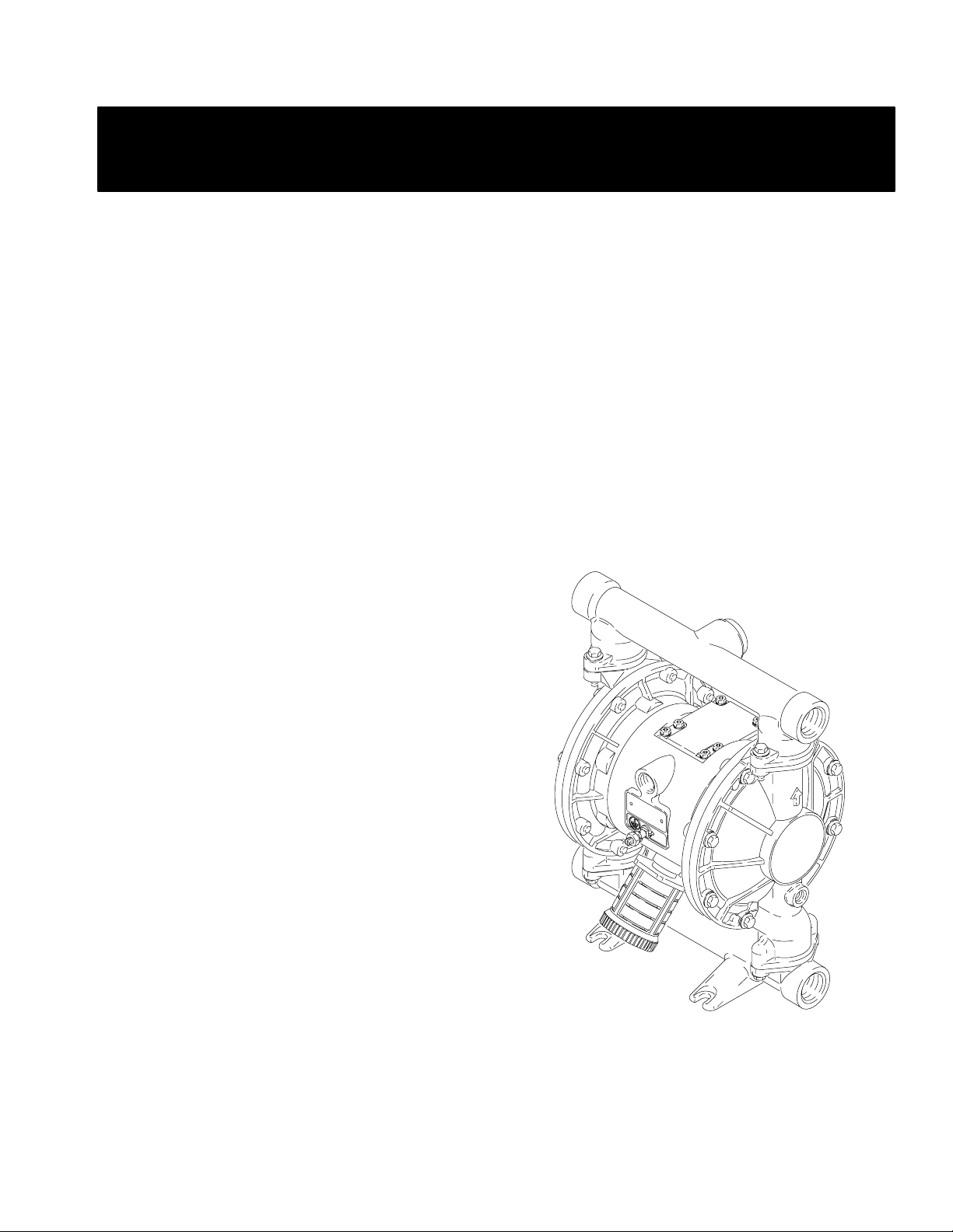
ALUMINUM
Air-Operated
Double Diaphragm Pumps
1” Model
Operations and
795–90653
GM 2–01
Maintenance
Instructions
WARNING/CAUTIONS
Read all these SAFETY INSTRUCTIONS
BEFORE installing or using this equip–
ment. Keep this manual handy for refer–
ence/training.
US and Foreign Patents Pending
1” Aluminum Model
Graymills Corporation 3705 N. Lincoln Avenue Chicago, Illinois 60613
773/248–6825 FAX 773/477–8673 www.graymills.com
02632
Page 2
Table of Contents
Symbols
Symbols 2. . . . . . . . . . . . . . . . . . . . . . . . . . . . . . . . . . . . . .
Safety Warnings 2. . . . . . . . . . . . . . . . . . . . . . . . . . . . . . .
Installation 5. . . . . . . . . . . . . . . . . . . . . . . . . . . . . . . . . . . . .
Operation 11. . . . . . . . . . . . . . . . . . . . . . . . . . . . . . . . . . . .
Maintenance 12. . . . . . . . . . . . . . . . . . . . . . . . . . . . . . . . . .
Troubleshooting 13. . . . . . . . . . . . . . . . . . . . . . . . . . . . . . .
Service 15. . . . . . . . . . . . . . . . . . . . . . . . . . . . . . . . . . . . . .
Dimensional Drawings 23. . . . . . . . . . . . . . . . . . . . . . . . .
Technical Data and Performance Chart 24. . . . . . . . . . .
Graymills Standard Warranty 26. . . . . . . . . . . . . . . . . . . .
Graymills Phone Number 26. . . . . . . . . . . . . . . . . . . . . . .
WARNING
Warning Symbol
WARNING
This symbol alerts you to the possibility of serious injury or
death if you do not follow the instructions.
Caution Symbol
CAUTION
This symbol alerts you to the possibility of damage to or
destruction of equipment if you do not follow the instructions.
Safety Alert Symbol
SAFETY ALERT
The safety Alert Symbol means ATTENTION! BECOME
ALERT! YOUR SAFETY IS INVOLVED!
HAZARDOUS FLUIDS
Improper handling of hazardous fluids or inhaling toxic vapors can cause extremely serious injury or death
from splashing in the eyes, ingestion, or bodily contamination. Observe all the following precautions when
you handle hazardous or potentially hazardous fluids.
D Know what fluid you are pumping and its specific hazards. Take precautions to avoid a toxic fluid spill.
D Always wear appropriate clothing and equipment, such as eye protection and breathing apparatus, to
protect yourself.
D Store hazardous fluid in an appropriate, approved container. Dispose of it according to all Local, State,
and Federal guidelines for hazardous fluids.
D Secure the fluid outlet hose tightly into the receiving container to prevent it from coming loose and
improperly draining the fluid.
D Pipe and dispose of the exhaust air safely, away from people, animals, and food handling areas. If the
diaphragm fails, the fluid is exhausted along with the air. See Air Exhaust Ventilation on page 10.
D Use static wire hoses when pumping flammables.
D Keep containers closed when not in use.
2
Page 3
WARNING
EQUIPMENT MISUSE HAZARD
Any misuse of the equipment or accessories, such as overpressurizing, modifying parts, using incompatible
chemicals and fluids, or using worn or damaged parts, can cause them to rupture and result in splashing in
the eyes or on the skin, other serious injury, or fire, explosion or property damage.
D This equipment is for professional use only. Observe all warnings. Read and understand all instruction
manuals, warning labels, and tags before you operate this equipment. If you are not sure, or if you have
questions about installation or operation, call Graymills Corporation.
D Never alter or modify any part of this equipment; doing so could cause it to malfunction.
D Check all equipment regularly and repair or replace worn or damaged parts immediately.
D Never exceed the recommended working pressure or the maximum air inlet pressure stated on your pump
or in the Technical Data on page 24.
D Do not exceed the maximum working pressure of the lowest rated component in your system. This
equipment has a 120 psi (0.8 MPa, 8 bar) maximum working pressure at 120 psi (0.8 MPa, 8 bar, )
maximum incoming air pressure.
D Be sure that all fluids and solvents used are chemically compatible with the wetted parts shown in the
Technical Data on page 24. Always read the manufacturer’s literature before you use fluid or solvent in
the pump.
D Never move or lift a pump under pressure. If dropped, the fluid section may rupture. Always follow the
Pressure Relief Procedure on page 11 before you move or lift the pump.
FIRE AND EXPLOSION HAZARD
Static electricity is created by the flow of fluid through the pump and hose. If the equipment is not properly
grounded, sparking may occur. Sparks can ignite fumes from solvents and the fluid being pumped, dust
particles, and other flammable substances, whether you are pumping indoors or outdoors, and can cause a
fire or explosion and serious injury and property damage.
D To reduce the risk of static sparking, ground the pump and all other equipment used or located in the
work area. Check your local electrical code for detailed grounding instructions for your area and type of
equipment. See Grounding on page 5.
D If you experience any static sparking or even a slight shock while using this equipment, stop pumping
immediately. Check the entire system for proper grounding. Do not use the system again until you have
identified and corrected the problem.
D Pipe and dispose of the exhaust air safely, away from all sources of ignition. If the diaphragm fails, the
fluid is exhausted along with the air. See Air Exhaust Ventilation on page 10.
D Do not smoke in the work area. Do not operate the equipment near a source of ignition or an open flame,
such as a pilot light.
3
Page 4
SAFETY PRECAUTIONS
CAUTION
D Verify the chemical compatibility of the pump wetted parts and the substance being pumped, flushed or
recirculated. Chemical compatibility may change with temperature and concentration of the chemical(s)
within the substance being pumped, flushed or recirculated.
D The pump should not be used for the structural support of the piping system. Be certain system compo-
nents are properly supported to prevent stress on the pump parts.
D Do not allow pump to operate dry for long periods of time; this may cause unnecessary wear or damage
to the pump.
D Maximum temperature limits are based upon mechanical stress only. Certain chemicals will significantly
reduce maximum safe operating temperatures. Consult Graymills for chemical compatibility and temperature limits.
United States Government safety standards have been adopted under the Occupational Safety and Health Act. You should
consult these standards—particularly the General Standards, Part 1910, and the Construction Standards, Part 1926.
4
Page 5
Installation
General Information
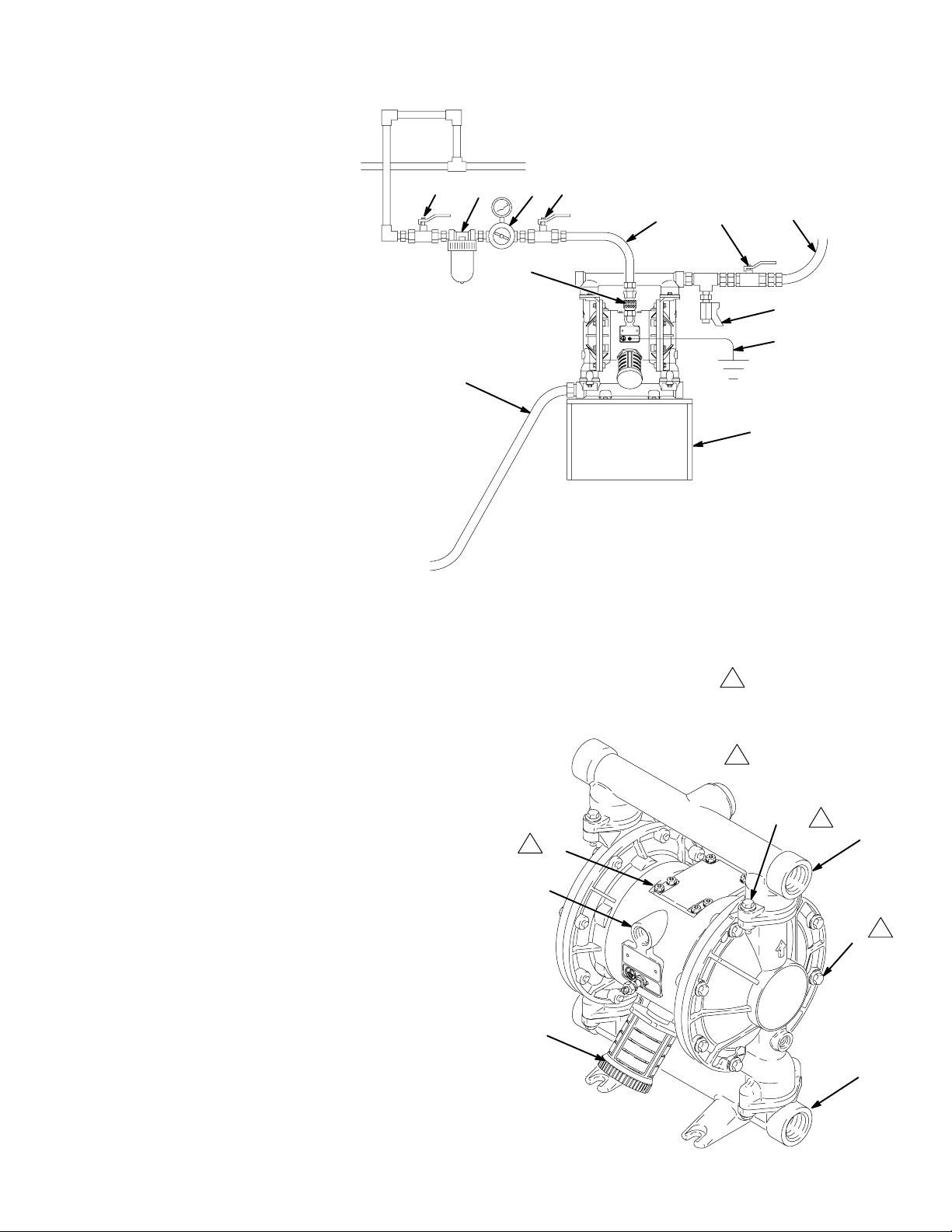
D The Typical Installations shown in Figs. 2–4 are only
guides for selecting and installing system components.
Contact Graymills for assistance in planning a system to
suit your needs.
D Always use Genuine Graymills Parts and Accessories.
D Reference numbers and letters in parentheses refer to
the callouts in the figures and the parts list.
WARNING
TOXIC FLUID HAZARD
Hazardous fluid or toxic fumes can cause
serious injury or death if splashed in the
eyes or on the skin, inhaled, or swallowed.
Grounding
WARNING
FIRE AND EXPLOSION HAZARD
This pump must be grounded. Before operating the pump, ground the system as explained below. Also, read the section FIRE
AND EXPLOSION HAZARD, on page 3.
To reduce the risk of static sparking, ground the pump and
all other equipment used or located in the pumping area.
Check your local electrical code for detailed grounding
instructions for your area and type of equipment. Ground
all of this equipment.
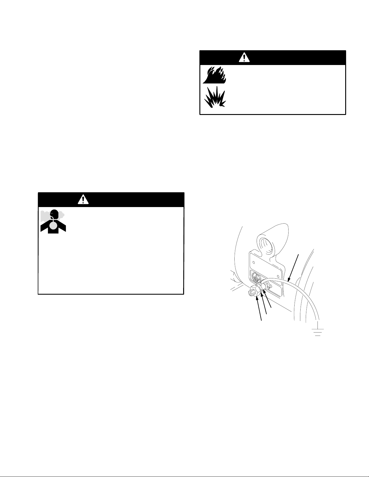
D Pump: Connect a ground wire and clamp as shown in
Fig. 1. Loosen the grounding lug locknut (W) and
washer (X). Insert one end of a 12 ga (1.5 mm@) minimum ground wire (Y) into the slot in the lug (Z) and
tighten the locknut securely. Connect the clamp end of
the ground wire to a true earth ground.
Figure 1
1. Read HAZARDOUS FLUIDS on page 2.
2. Use fluids and solvents which are compatible with
the equipment wetted parts. Refer to the Technical
Data section of all equipment manuals. Read the
fluid and solvent manufacturer’s warnings.
Tightening Screws Before First Use
After you unpack the pump, and before you use it for the
first time, check and retorque external fasteners. Retorque
the fluid cover screws first, then the manifold screws. This
keeps the manifolds from interfering with tightening the
fluid covers. See the Service section for torque specifications.
After the first day of operation, check and retorque the
fasteners again. Although the recommended frequency for
retorquing fasteners varies with pump usage, a general
guideline is to retorque fasteners every two months.
Y
Z
X
W
02646
D Air and fluid hoses: Use only grounded hoses with a
maximum of 500 ft (150 m) combined hose length to
ensure grounding continuity.
D Air compressor: Follow the manufacturer’s recommen-
dations.
D All solvent pails used when flushing: Follow the local
code. Use only metal pails, which are conductive. Do
not place the pail on a non-conductive surface, such as
paper or cardboard, which interrupts the grounding
continuity.
D Fluid supply container: Follow the local code.
5
Page 6
Installation
Mountings
CAUTION
The pump exhaust air may contain contaminants.
Ventilate to a remote area if the contaminants could
affect your fluid supply. See Air Exhaust Ventilation
on page 10.
D Be sure the mounting surface can support the weight of
the pump, hoses, and accessories, as well as the stress
caused during operation.
D For all mountings, be sure the pump is bolted directly to
the mounting surface.
D For ease of operation and service, mount the pump so
the air valve cover (2), air inlet, and fluid inlet and
outlet ports are easily accessible.
b. Locate one bleed-type master air valve (B) close
to the pump and use it to relieve trapped air. See
the WARNING above. Locate the other master air
valve (E) upstream from all air line accessories
and use it to isolate them during cleaning and
repair.
c. The air line filter (F) removes harmful dirt and
moisture from the compressed air supply.
2. Install a grounded, flexible air hose (A) between the
accessories and the 1/2 npt(f) pump air inlet (N). See
Fig. 5. Use a minimum 3/8” (9.5 mm) ID air hose.
Screw an air line quick disconnect coupler (D) onto the
end of the air hose (A), and screw the mating fitting
into the pump air inlet snugly. Do not connect the
coupler (D) to the fitting until you are ready to operate
the pump.
Installation of Remote Pilot Air Lines
1. Connect air line to pump as in preceding steps.
2. Connect 1/4 in. O.D. tubing to push type connectors
(14) on air motor of pump.
Air Line
WARNING
A bleed-type master air valve (B) is required in your
system to relieve air trapped between this valve and the
pump. Trapped air can cause the pump to cycle unexpectedly, which could result in serious injury, including
splashing in the eyes or on the skin, injury from moving parts, or contamination from hazardous fluids. See
Fig. 3.
1. Install the air line accessories as shown in Figs. 2–4 on
pages 8 and 9. Mount these accessories on the wall
or on a bracket. Be sure the air line supplying the
accessories is grounded.
a. Install an air regulator (C) and gauge to control the
fluid pressure. The fluid outlet pressure will be the
same as the setting of the air regulator.
NOTE: by replacing the push type connectors, other sizes
or types of fittings may be used. The new fittings will
require 1/8 in. npt threads.
NOTE: the air pressure at the connectors must be at least
30% of the air pressure to the air motor for the pump to
operate.
Fluid Suction Line
1. Use grounded fluid hoses. The pump fluid inlet (R) is
1” npt(f). See Fig. 5. Screw the fluid fitting into the
pump inlet securely.
2. If the fluid inlet pressure to the pump is more than 25%
of the outlet working pressure, the ball check valves
will not close fast enough, resulting in inefficient pump
operation.
3. At inlet fluid pressures greater than 15 psi (0.1 MPa, 1
bar), diaphragm life will be shortened.
4. See the Technical Data on page 24 for maximum
suction lift (wet and dry).
6
Page 7
Installation
Fluid Outlet Line
WARNING
A fluid drain valve (J) is required to relieve pressure in
the hose if it is plugged. The drain valve reduces the
risk of serious injury, including splashing in the eyes or
on the skin, or contamination from hazardous fluids
when relieving pressure. Install the valve close to the
pump fluid outlet. See Fig. 3.
1. Use grounded fluid hoses (L). The pump fluid outlet
(S) is 1” npt(f). See Fig. 5. Screw the fluid fitting into
the pump outlet securely.
2. Install a fluid drain valve (J) near the fluid outlet. See the
WARNING at left, and Figs. 2–4 on pages 8 and 9.
3. Install a shutoff valve (K) in the fluid outlet line.
7
Page 8
Installation
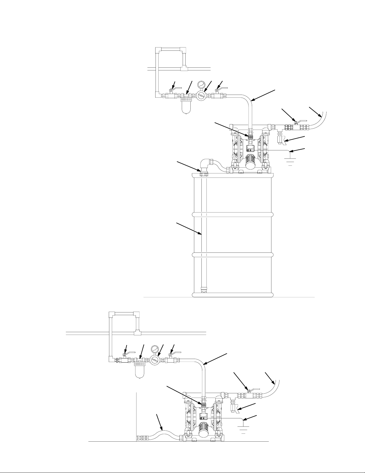
Figure 2
KEY FOR FIG. 2
A Air supply line
B Bleed-type master air valve
(required for pump)
C Air regulator
D Air line quick disconnect
E Master air valve (for accessories)
F Air line filter
G Fluid suction line
H Bung adapter
J Fluid drain valve (required)
K Fluid shutoff valve
L Fluid line
Y Ground wire (required; see page 5
for installation instructions)
TYPICAL BUNG-MOUNT INSTALLATION
FBE C
A
KL
D
J
Y
H
Figure 3
KEY FOR FIG. 3
A Air supply line
B Bleed-type master air valve
(required for pump)
C Air regulator
D Air line quick disconnect
E Master air valve (for accessories)
F Air line filter
G Fluid suction line
J Fluid drain valve (required)
K Fluid shutoff valve
L Fluid line
Y Ground wire (required; see page 5
for installation instructions)
G
02648
TYPICAL FLOOR-MOUNT INSTALLATION
FBE C
A
KL
D
J
G
Y
02651
8
Page 9
Installation
Figure 4
KEY FOR FIG. 4
A Air supply line
B Bleed-type master air valve
(required for pump)
C Air regulator
D Air line quick disconnect
E Master air valve (for accessories)
F Air line filter
G Fluid suction line
J Fluid drain valve (required)
K Fluid shutoff valve
L Fluid line
M Wall mounting bracket
Y Ground wire (required; see page 5
for installation instructions)
G
FBE C
D
TYPICAL WALL-MOUNT INSTALLATION
A
KL
J
Y
M
Changing the Orientation of the Fluid Inlet
and Outlet Ports
On aluminum pumps, the fluid inlet and outlet manifolds
have threaded ports on both ends. The pump is shipped
with a plug installed in one end of each manifold, and the
opposite end open. See Fig. 5. To change the orientation of
the inlet and/or outlet port, remove the plug from one end
of a manifold and install it in the opposite end.
Figure 5
KEY
N 1/2 npt(f) air inlet port
P Muffler. Air exhaust port is 3/4 npt(f)
R 1 npt(f) fluid inlet port
S 1 npt(f) fluid outlet port
106 Manifold and cover screws
3 Air valve screws
2
3
N
Apply medium-strength
1
(blue) LoctiteR or equivalent to the threads, and
torque to 120–150 in-lb
(14–17 N.m).
Torque to 38–43 in-lb
2
(4.4–5.0 N.m).
1
106
106
02649
S
1
P
R
02632
9
Page 10
Installation
Air Exhaust Ventilation
WARNING
FIRE AND EXPLOSION HAZARD
Be sure to read and follow the warnings and
precautions regarding HAZARDOUS
FLUIDS, and FIRE OR EXPLOSION
HAZARD on pages 2 and 3, before operat-
ing this pump.
Be sure the system is properly ventilated for your type
of installation. You must vent the exhaust to a safe
place, away from people, animals, food handling areas,
and all sources of ignition when pumping flammable or
hazardous fluids.
Diaphragm failure will cause the fluid being pumped to
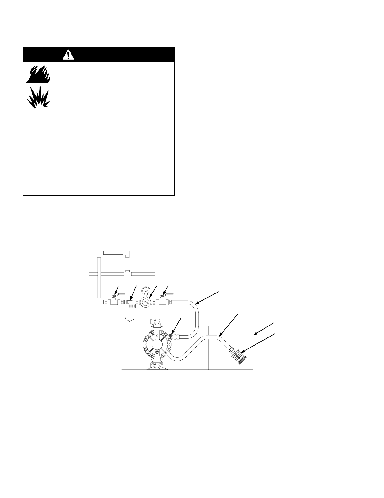
exhaust with the air. Place an appropriate container at
the end of the air exhaust line to catch the fluid. See
Fig. 6.
Figure 6
VENTING EXHAUST AIR
FBEC
The air exhaust port is 3/4 npt(f). Do not restrict the air
exhaust port. Excessive exhaust restriction can cause erratic
pump operation.
To provide a remote exhaust:
1. Remove the muffler (P) from the pump air exhaust
port.
2. Install a grounded air exhaust hose (T) and connect the
muffler (P) to the other end of the hose. The minimum
size for the air exhaust hose is 3/4 in. (19 mm) ID. If a
hose longer than 15 ft (4.57 m) is required, use a larger
diameter hose. Avoid sharp bends or kinks in the hose.
3. Place a container (U) at the end of the air exhaust line
to catch fluid in case a diaphragm ruptures. See Fig. 6.
KEY
A Air supply line
B Bleed-type master air valve
(required for pump)
C Air regulator
D Air line quick disconnect
E Master air valve (for accessories)
F Air line filter
P Muffler
T Grounded air exhaust hose
A
U Container for remote air exhaust
10
D
T
U
P
02650
Page 11
Operation
Pressure Relief Procedure
WARNING
PRESSURIZED EQUIPMENT HAZARD
The equipment stays pressurized until pressure is manually relieved. To reduce the risk of serious injury from
pressurized fluid, accidental spray from the gun or
splashing fluid, follow this procedure whenever you
D Are instructed to relieve pressure
D Stop pumping
D Check, clean or service any system equipment
D Install or clean fluid nozzles
1. Shut off the air to the pump.
2. Open the dispensing valve, if used.
3. Open the fluid drain valve to relieve fluid pressure,
having a container ready to catch the drainage.
Flush the Pump Before First Use
The pump was tested in water. If the water could contaminate the fluid you are pumping, flush the pump thoroughly
with a compatible solvent. Follow the steps under Starting
and Adjusting the Pump.
Starting and Adjusting the Pump
WARNING
TOXIC FLUID HAZARD
To reduce the risk of serious injury, splashing in the eyes or on the skin, and toxic
fluid spills, never move or lift a pump un-
der pressure. If dropped, the fluid section may rupture.
Always follow the Pressure Relief Procedure Warn-
ing above before lifting the pump.
1. Be sure the pump is properly grounded. Refer to
Grounding on page 5.
2. Check fittings to be sure they are tight. Use a compatible liquid thread sealant on male threads. Tighten
fluid inlet and outlet fittings securely.
5. Close the fluid drain valve (J).
6. Back out the air regulator (C) knob, and open all
bleed-type master air valves (B, E).
7. If the fluid hose has a dispensing device, hold it open
while continuing with the following step.
8. Slowly increase air pressure with the air regulator (C)
until the pump starts to cycle. Allow the pump to cycle
slowly until all air is pushed out of the lines and the
pump is primed.
If you are flushing, run the pump long enough to
thoroughly clean the pump and hoses. Close the air
regulator. Remove the suction tube from the solvent
and place it in the fluid to be pumped.
Operation of Remote Piloted Pumps
1. Follow preceding steps 1 through 7 of Starting and
Adjusting Pump.
2. Open air regulator (C).
WARNING
The pump may cycle once before the external signal is
applied. Injury is possible. If pump cycles, wait until
end before proceeding.
3. Pump will operate when air pressure is alternately
applied and relieved to push type connectors (14).
NOTE: Leaving air pressure applied to the air motor for
extended periods when the pump is not running may
shorten the diaphragm life. Using a 3–way solenoid valve
to automatically relieve the pressure on the air motor when
the metering cycle is complete prevents this from occurring.
Pump Shutdown
3. Place the suction tube (if used) in fluid to be pumped.
NOTE: If fluid inlet pressure to the pump is more than
25% of outlet working pressure, the ball check valves will
not close fast enough, resulting in inefficient pump operation.
4. Place the end of fluid hose (L) into an appropriate
container.
WARNING
To reduce the risk of serious injury whenever you are
instructed to relieve pressure, always follow the Pres-
sure Relief Procedure at left.
At the end of the work shift, relieve the pressure.
11
Page 12
Maintenance
Lubrication
The air valve is designed to operate unlubricated, however
if lubrication is desired, every 500 hours of operation (or
monthly) remove the hose from the pump air inlet and add
two drops of machine oil to the air inlet.
CAUTION
Do not over-lubricate the pump. Oil is exhausted
through the muffler, which could contaminate your
fluid supply or other equipment. Excessive lubrication
can also cause the pump to malfunction.
Flushing and Storage
WARNING
To reduce the risk of serious injury whenever you are
instructed to relieve pressure, always follow the Pres-
sure Relief Procedure on page 11.
Flush the pump often enough to prevent the fluid you are
pumping from drying or freezing in the pump and damaging it. Use a compatible solvent.
Tightening Threaded Connections
Before each use, check all hoses for wear or damage, and
replace as necessary. Check to be sure all threaded connections are tight and leak-free. Check and retorque all
threaded connections at least every two months. Retorque
the fluid cover screws first, followed by the manifold
screws.
The recommended frequency for retorquing of fasteners
varies with pump usage; a general guideline is to retorque
fasteners every two months.
Preventive Maintenance Schedule
Establish a preventive maintenance schedule, based on the
pump’s service history. This is especially important for
prevention of spills or leakage due to diaphragm failure.
Always flush the pump and relieve the pressure before
storing it for any length of time.
12
Page 13
Troubleshooting
D Relieve the pressure before checking or servicing the
WARNING
To reduce the risk of serious injury whenever you are
instructed to relieve pressure, always follow the Pres-
sure Relief Procedure on page 11.
PROBLEM CAUSE SOLUTION
equipment.
D Check all possible problems and causes before disas-
sembling the pump.
Pump cycles at stall or fails to hold
pressure at stall.
Pump will not cycle, or cycles once
and stops.
Pump operates erratically. Clogged suction line. Inspect; clear.
Air bubbles in fluid. Suction line is loose. Tighten.
Worn check valve balls (301), seats
(201) or o-rings (202).
Air valve is stuck or dirty. Disassemble and clean air valve. See
Check valve ball (301) severely worn
and wedged in seat (201) or manifold
(102 or 103).
Check valve ball (301) is wedged into
seat (201), due to overpressurization.
Dispensing valve clogged. Relieve pressure and clear valve.
Sticky or leaking balls (301). Clean or replace. See page 17.
Diaphragm ruptured. Replace. See pages 18–20.
Restricted exhaust. Remove restriction.
Diaphragm ruptured. Replace. See pages 18–20.
Loose inlet manifold (102), damaged
seal between manifold and seat (201),
damaged o-rings (202).
Replace. See page 17.
page 15. Use filtered air.
Replace ball and seat. See page 17.
Install Pressure Relief Valve.
Tighten manifold bolts (106) or replace seats (201) or o-rings (202). See
page 17.
Loose diaphragm shaft bolt (107). Tighten or replace (pages 18–20).
Damaged o-ring (108). Replace. See pages 18–20.
13
Page 14
Troubleshooting
PROBLEM CAUSE SOLUTION
Fluid in exhaust air. Diaphragm ruptured. Replace. See pages 18–20.
Loose diaphragm shaft bolt (107). Tighten or replace (pages 18–20).
Damaged o-ring (108). Replace. See pages 18–20.
Pump exhausts excessive air at stall. Worn air valve block (7), o-ring (6),
plate (8), pilot block (18), u-cups (10),
or pilot pin o-rings (17).
Worn shaft seals (402). Replace. See pages 18–20.
Pump leaks air externally. Air valve cover (2) or air valve cover
screws (3) are loose.
Air valve gasket (4) or air cover gasket
(22) is damaged.
Air cover screws (25) are loose. Tighten screws. See pages 21–22.
Pump leaks fluid externally from ball
check valves.
Loose manifolds (102, 103), damaged
seal between manifold and seat (201),
damaged o-rings (202).
Repair or replace. See page 15.
Tighten screws. See page 15.
Inspect; replace. See pages 15, 21–22.
Tighten manifold bolts (106) or replace seats (201) or o-rings (202). See
page 17.
14
Page 15
Service
Repairing the Air Valve
Tools Required
D Torque wrench
D Torx screwdriver or 8 mm (5/16”) socket wrench
D Needle-nose pliers
D O-ring pick
D Lithium base grease
NOTE: Air Valve Repair Kit 784–90616 is available.
Disassembly
WARNING
To reduce the risk of serious injury whenever you are
instructed to relieve pressure, always follow the Pres-
sure Relief Procedure on page 11.
1. Relieve the pressure.
2. With a torx screwdriver or 8 mm (5/16”) socket
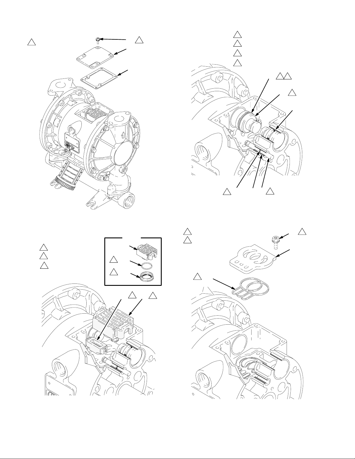
wrench, remove the six screws (3), air valve cover (2),
and gasket (4). See Fig. 7.
3. Move the valve carriage (5) to the center position and
pull it out of the cavity. Remove the valve block (7)
and o-ring (6) from the carriage. Using a needle-nose
pliers, pull the pilot block (18) straight up and out of
the cavity. See Fig. 8.
4. Pull the two actuator pistons (11) out of the bearings
(12). Remove the u-cup packings (10) from the pistons.
Pull the pilot pins (16) out of the bearings (15). Remove the o-rings (17) from the push pins. See Fig. 9.
5. Inspect the valve plate (8) in place. If damaged, use a
torx screwdriver or 8 mm (5/16”) socket wrench to
remove the three screws (3). Remove the valve plate
(8) and seal (9). See Fig. 10.
6. Inspect the bearings (12, 15) in place. See Fig. 9. The
bearings are tapered and, if damaged, must be removed
from the outside. This requires disassembly of the fluid
section. See page 21.
7. Clean all parts and inspect for wear or damage. Replace as needed. Reassemble as explained on page 15.
Reassembly
1. If you replaced the bearings (12, 15), reinstall as
explained on page 21. Reassemble the fluid section.
2. Install the valve plate seal (9{) into the groove at the
bottom of the valve cavity. The rounded side of the
seal must face down into the groove. See Fig. 10.
3. Install the valve plate (8) in the cavity. The plate is
reversible, so either side can face up. Install the three
screws (3), using a torx screwdriver or 8 mm (5/16”)
socket wrench. Tighten until the screws bottom out on
the housing. See Fig. 10.
4. Install an o-ring (17{) on each pilot pin (16). Grease
the pins and o-rings. Insert the pins into the bearings
(15), narrow end first. See Fig. 9.
5. Install a u-cup packing (10{) on each actuator piston
(11), so the lips of the packings face the narrow end of
the pistons. See Fig. 9.
6. Lubricate the u-cup packings (10{) and actuator
pistons (11). Insert the actuator pistons in the bearings
(12), wide end first. Leave the narrow end of the
pistons exposed. See Fig. 9.
7. Grease the lower face of the pilot block (18{) and
install so its tabs snap into the grooves on the ends of
the pilot pins (16). See Fig. 8.
8. Grease the o-ring (6{) and install it in the valve block
(7{). Push the block onto the valve carriage (5). Grease
the lower face of the valve block. See Fig. 8.
9. Install the valve carriage (5) so its tabs slip into the
grooves on the narrow end of the actuator pistons (11).
See Fig. 8.
10. Align the valve gasket (4{) and cover (2) with the six
holes in the center housing (1). Secure with six screws
(3), using a torx screwdriver or 8 mm (5/16”) socket
wrench. Torque to 38–43 in-lb (4.3–4.9 N.m). See Fig.
7.
15
Page 16
Service
Figure 7
Torque to 38–43 in-lb
2
(4.3–4.9 N.m).
3
2
4{
2
Figure 9
1
Insert narrow end first.
2
Grease.
Install with lips facing
3
narrow end of piston (11).
4
Insert wide end first.
10{
342
11
12
17{ 16
2
15
1
Figure 8
1
See Detail at right.
2
Grease.
3
Grease lower face.
Detail
5
2
{6
3
{7
18{ 5
02644
02643
Figure 10
1
Rounded side must face down.
2
Tighten screws until
they bottom out on
the housing.
1
{9
3
1
2
3
8
16
02642
02645
Page 17
Service
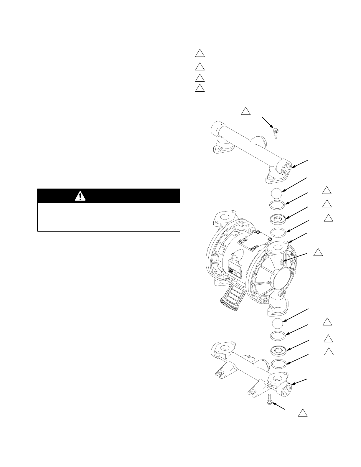
Ball Check Valve Repair
Tools Required
D Torque wrench
D 10 mm socket wrench
D O-ring pick
Disassembly
NOTE: A Fluid Section Repair Kit is available. Use
784–90617 for Hytrel Diaphragm pumps and 784–90618
for Teflon Diaphragm pumps.
NOTE: To ensure proper seating of the balls (301), always
replace the seats (201) when replacing the balls. Also
replace the o-rings (202).
WARNING
To reduce the risk of serious injury whenever you
are instructed to relieve pressure, always follow the
Pressure Relief Procedure on page 11.
Figure 11
Apply medium-strength (blue) LoctiteR or equivalent to the
1
threads, and torque to 120–150 in-lb (14–17 N.m).
Arrow (A) must point toward outlet manifold (103).
2
3
Beveled seating surface must face the ball (301).
4
Not used on some models.
1
106
103
301*
202*
201*
202*
101
4
3
4
1. Relieve the pressure. Disconnect all hoses.
2. Remove the pump from its mounting.
3. Using a 10 mm socket wrench, remove the four bolts
(106) holding the outlet manifold (103) to the fluid
covers (101). See Fig. 11.
4. Remove the o-rings (202), seats (201), and balls (301)
from the manifold (103).
5. Turn the pump over and remove the inlet manifold
(102). Remove the o-rings (202), seats (201), and balls
(301) from the fluid covers (101).
Reassembly
1. Clean all parts and inspect for wear or damage. Replace parts as needed.
2. Reassemble in the reverse order, following all notes in
Fig. 11. Be sure the ball checks and manifolds are
assembled exactly as shown. The arrows (A) on the
fluid covers (101) must point toward the outlet manifold (103).
106
A
2
301*
202*
4
201*
3
4
202*
102
1
02647A
17
Page 18
Service
Diaphragm Repair
Tools Required
D Torque wrench
D 10 mm socket wrench
D 15 mm socket wrench (aluminum models) or
1” socket wrench (stainless steel models)
D 19 mm socket wrench
D O-ring pick
D Lithium-base grease
Disassembly
NOTE: A Fluid Section Repair Kit is available. Use
784–90617 for Hytrel pumps and 784–90618 for Teflon
pumps.
Figure 12
WARNING
To reduce the risk of serious injury whenever you are
instructed to relieve pressure, always follow the Pres-
sure Relief Procedure on page 11.
1. Relieve the pressure.
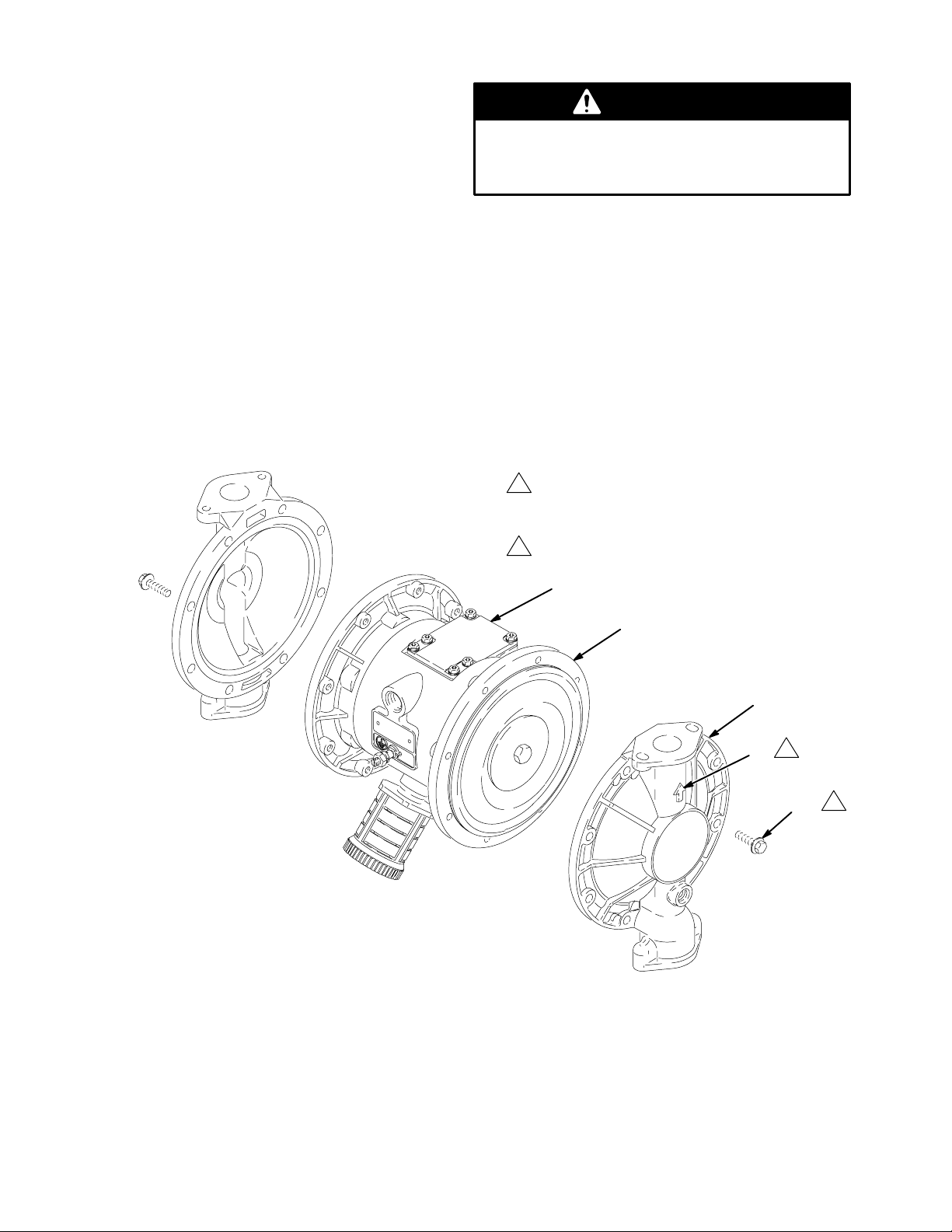
2. Remove the manifolds and disassemble the ball check
valves as explained on page 17.
3. Using a 10 mm socket wrench, remove the screws
(106) holding the fluid covers (101) to the air covers
(23). Pull the fluid covers (101) off the pump. See Fig.
12.
1
Apply medium-strength (blue) LoctiteR or equivalent to
the threads, and torque to 120–150 in-lb (14–17 N.m).
2
Arrow (A) must point toward air valve (B).
B
23
101
A
2
106
1
18
02635A
Page 19

Service
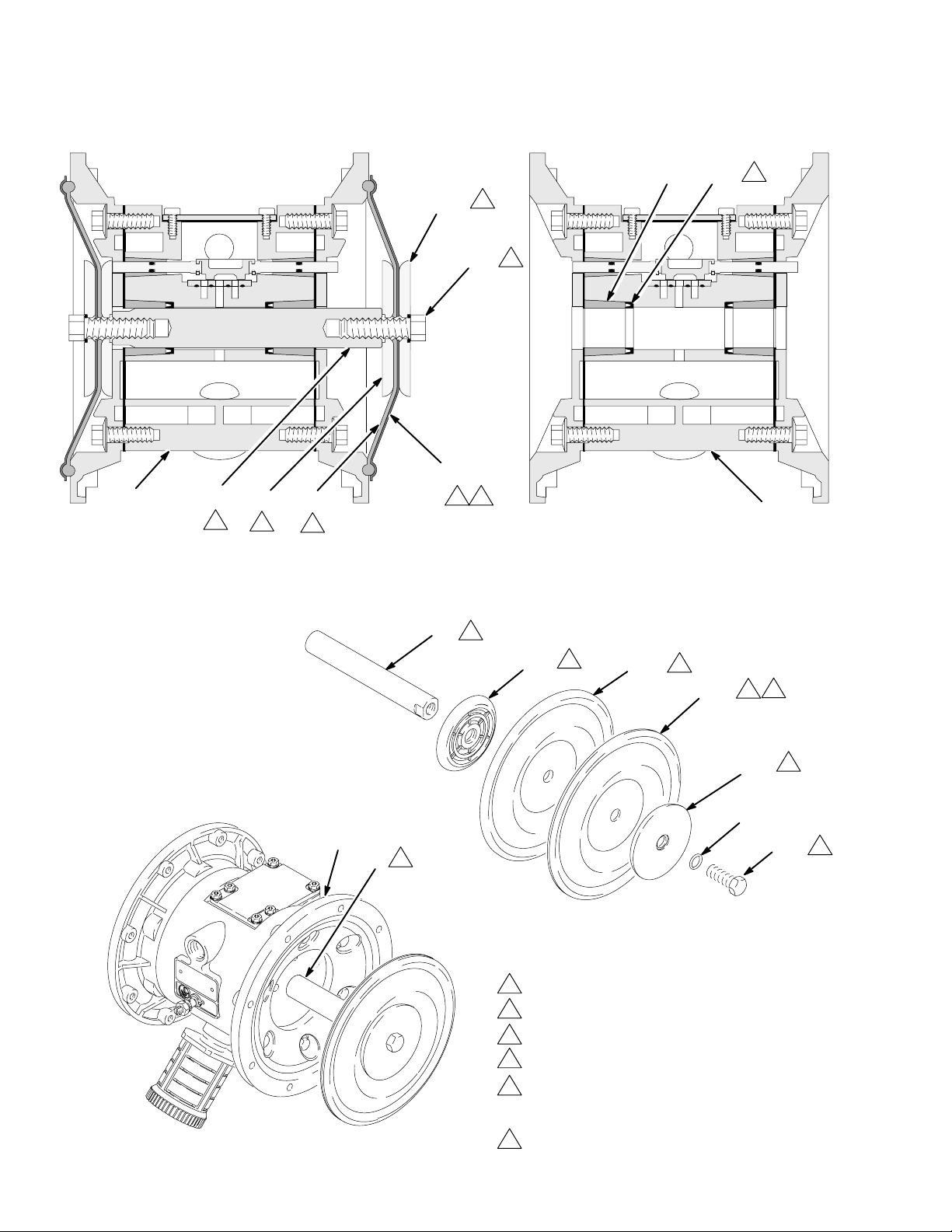
4. Loosen but do not remove the diaphragm shaft bolts
(107), using a 15 mm socket wrench (1” on stainless
steel models) on both bolts.
5. Unscrew one bolt from the diaphragm shaft (24) and
remove the o-ring (108), fluid side diaphragm plate
(105), TeflonR diaphragm (403, used on TeflonR
models only), diaphragm (401), and air side diaphragm
plate (104). See Fig. 13.
6. Pull the other diaphragm assembly and the diaphragm
shaft (24) out of the center housing (1). Hold the shaft
flats with a 19 mm socket wrench, and remove the bolt
(107) from the shaft. Disassemble the remaining
diaphragm assembly.
7. Inspect the diaphragm shaft (24) for wear or scratches.
If it is damaged, inspect the bearings (19) in place. If
the bearings are damaged, refer to page 21.
8. Reach into the center housing (1) with an o-ring pick
and hook the u-cup packings (402), then pull them out
of the housing. This can be done with the bearings (19)
in place.
c. On TeflonR models only, install the TeflonR
diaphragm (403*). Make certain the side marked
AIR SIDE faces the center housing (1).
d. Install the diaphragm (401*) on the bolt. Make
certain the side marked AIR SIDE faces the center
housing (1).
e. Install the air side diaphragm plate (104) so the
rounded side faces the diaphragm (401). This plate
is used on all models, and is stamped with its part
number.
f. Apply medium-strength (blue) LoctiteR or equiv-
alent to the bolt (107) threads. Screw the bolt into
the shaft (24) hand tight.
3. Grease the length and ends of the diaphragm shaft (24),
and slide it through the housing (1).
4. Assemble the other diaphragm assembly to the shaft as
explained in step 2.
9. Clean all parts and inspect for wear or damage. Replace parts as needed.
Reassembly
1. Install the shaft u-cup packings (402*) so the lips face
out of the housing (1). Lubricate the packings. See Fig.
13.
2. Install the diaphragm assembly on one end of the shaft
(24) as follows:
a. Install the o-ring (108*) on the shaft bolt (107).
b. Install the fluid side diaphragm plate (105) on the
bolt so the rounded side faces the diaphragm
(401).
5. Hold one shaft bolt (107) with a wrench and torque the
other bolt to 20–25 ft-lb (27–34 N.m) at 100 rpm
maximum.
6. Align the fluid covers (101) and the center housing (1)
so the arrows (A) on the covers face the same direction
as the air valve (B). Apply medium-strength (blue)
LoctiteR or equivalent to the threads of the screws
(106). Secure the covers with the screws handtight.
See Fig. 12. Using a 10 mm socket wrench, torque the
screws oppositely and evenly to 120–150 in-lb (14–17
N.m).
7. Reassemble the ball check valves and manifolds as
explained on page 17.
19
Page 20
Service
Figure 13
105
2
107
19 402*
5
1
403*
3
1
24 104 401*
4
2
3
02638A
6
1
02637A
Cutaway View, with Diaphragms in Place Cutaway View, with Diaphragms Removed
24
4
2
104
401*
3
6
3
403*
105
2
108*
1
107
24
4
1
Lips face out of housing (1).
2
Rounded side faces diaphragm (401).
3
Air Side must face center housing (1).
4
Grease.
5
20
5
Apply medium-strength (blue) LoctiteR or
equivalent. Torque to 20–25 ft-lb (27–34 N-m) at 100
rpm maximum.
6
Used on pumps with TeflonR diaphragms only.
02636A
Page 21
Service
Bearing and Air Gasket Removal
Tools Required
D Torque wrench
D 10 mm socket wrench
D Bearing puller
D O-ring pick
D Press, or block and mallet
Disassembly
NOTE: Do not remove undamaged bearings.
WARNING
To reduce the risk of serious injury whenever you
are instructed to relieve pressure, always follow the
Pressure Relief Procedure on page 11.
1. Relieve the pressure.
2. Remove the manifolds and disassemble the ball check
valves as explained on page 17.
3. Remove the fluid covers and diaphragm assemblies as
explained on page 18.
NOTE: If you are removing only the diaphragm shaft
bearing (19), skip step 4.
4. Disassemble the air valve as explained on page 15.
5. Using a 10 mm socket wrench, remove the screws (25)
holding the air covers (23) to the center housing (1).
See Fig. 14.
Reassembly
1. If removed, install the shaft u-cup packings (402*) so
the lips face out of the housing (1).
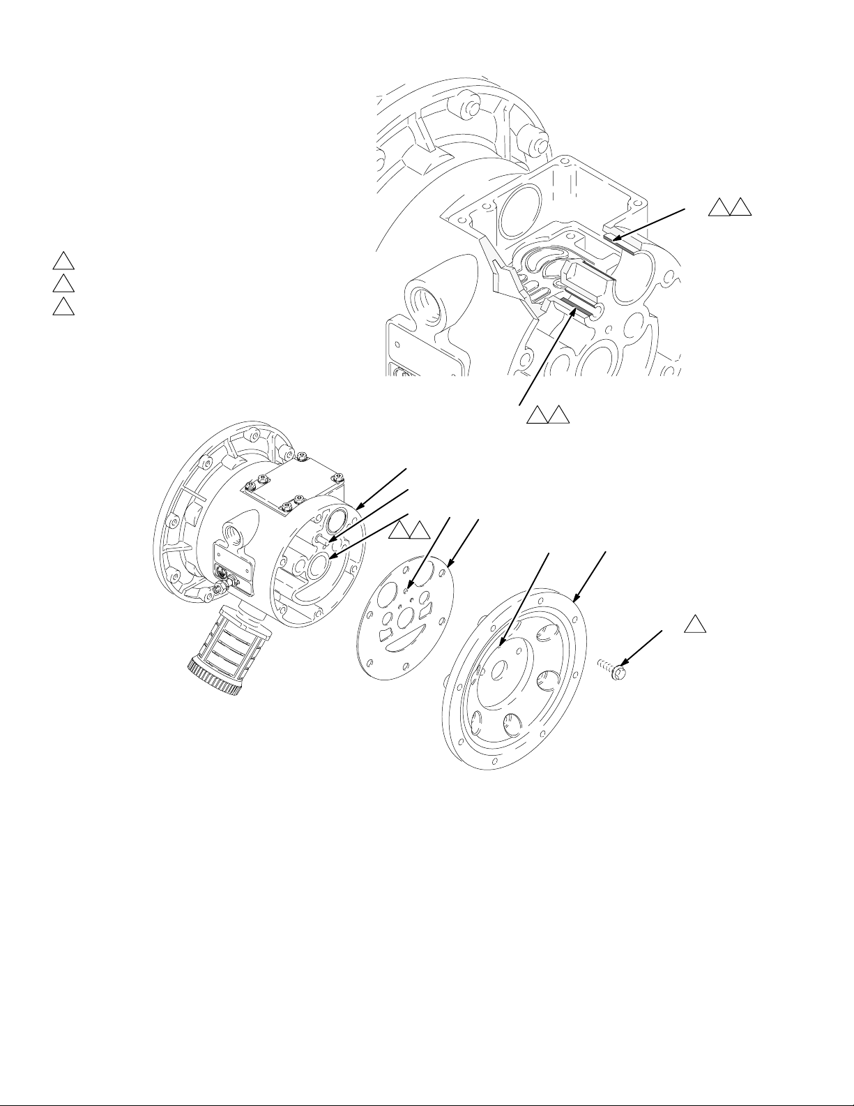
2. The bearings (12, 15, and 19) are tapered and can only
be installed one way. Insert the bearings into the center
housing (1), tapered end first. Using a press or a block
and rubber mallet, press-fit the bearing so it is flush
with the surface of the center housing.
3. Reassemble the air valve as explained on page 15.
4. Align the new air cover gasket (22) so the pilot pin
(16) protruding from the center housing (1) fits through
the proper hole (H) in the gasket.
5. Align the air cover (23) so the pilot pin (16) fits in the
middle hole (M) of the three small holes near the
center of the cover. Install the screws (25), handtight.
Apply medium-strength (blue) LoctiteR or equivalent
to the threads of the screws (25). See Fig. 14. Using a
10 mm socket wrench, torque the screws oppositely
and evenly to 130–150 in-lb (15–17 N.m).
6. Install the diaphragm assemblies and fluid covers as
explained on page 18.
7. Reassemble the ball check valves and manifolds as
explained on page 17.
6. Remove the air cover gaskets (22). Always replace the
gaskets with new ones.
7. Use a bearing puller to remove the diaphragm shaft
bearings (19), air valve bearings (12) or pilot pin
bearings (15). Do not remove undamaged bearings.
8. If you removed the diaphragm shaft bearings (19)
reach into the center housing (1) with an o-ring pick
and hook the u-cup packings (402), then pull them out
of the housing. Inspect the packings. See Fig. 13.
21
Page 22
Service
Figure 14
1
Insert bearings tapered end first.
2
Press-fit bearings flush with surface of center housing (1).
3
Apply medium-strength (blue) LoctiteR or equivalent.
Torque to 130–150 in-lb (15–17 N.m).
15
12
2
1
2
1
02640
Detail of Air Valve Bearings
1
16
22
H
19
2
1
M
23
25
3
02639A
22
Page 23
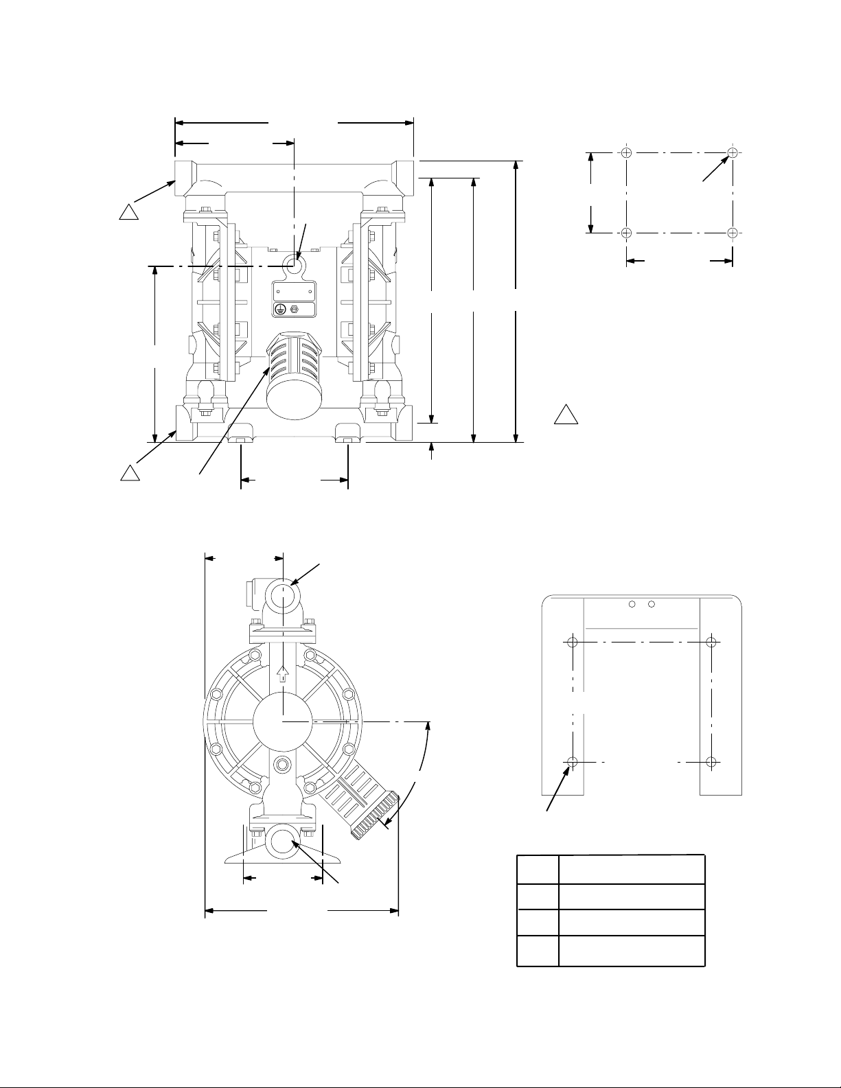
Dimensional Drawings
FRONT VIEW
12.0 in.
6.0 in.
(152 mm)
(305 mm)
PUMP MOUNTING
HOLE PATTERN
1
1 npt(f)
Optional
Fluid Outlet
(218.4 mm)
1
1 npt(f)
Optional
Fluid Inlet
8.6 in.
3/4 npt(f)
Air Exhaust
(muffler
included)
3.95 in.
(100 mm)
5.5 in.
(139.5 mm)
1/2 npt(f)
Air Inlet
1 npt(f)
Fluid
Outlet
A
1.0 in.
(25.5 mm)
7437A
5.0 in.
(127 mm)
B
C
On aluminum pumps only.
1
Four 0.5 in.
(12.5 mm)
diameter holes
5.5 in.
(139.5 mm)
WALL BRACKET
MOUNTING HOLE PATTERN
(Viewed from Wall)
SIDE VIEW
5.0 in.
(127 mm)
9.25 in.
(235 mm)
1 npt(f)
Fluid Inlet
45°
5.38 in.
(136.7 mm)
(158.5 mm)
Four 0.437 in. (11.1 mm)
diameter holes
Dim.
A
B
C
Alum. Pumps
12.58 in. (319.5 mm)
13.58 in. (345.0 mm)
14.48 in. (367.8 mm)
6.24 in.
02681
23
Page 24

Technical Data
Maximum fluid working pressure 120 psi. . . . . . . . . . . . . . . . . . . . . . . . . . . . . . . . . . . . . . . . . . . . . . . . . . . . . . . . . . . . . . . . . . .
(0.8 MPa, 8 bar)
Air pressure operating range 20–120 psi. . . . . . . . . . . . . . . . . . . . . . . . . . . . . . . . . . . . . . . . . . . . . . . . . . . . . . . . . . . . . . . . . . . .
(0.14–0.8 MPa, 1.4–8 bar)
Maximum air consumption 60 scfm. . . . . . . . . . . . . . . . . . . . . . . . . . . . . . . . . . . . . . . . . . . . . . . . . . . . . . . . . . . . . . . . . . . . . . . .
Air consumption at 70 psi/20 gpm 20 scfm (see chart). . . . . . . . . . . . . . . . . . . . . . . . . . . . . . . . . . . . . . . . . . . . . . . . . . . . . . . . .
Maximum free-flow delivery 42 gpm (159 l/min). . . . . . . . . . . . . . . . . . . . . . . . . . . . . . . . . . . . . . . . . . . . . . . . . . . . . . . . . . . . .
Maximum pump speed 276 cpm. . . . . . . . . . . . . . . . . . . . . . . . . . . . . . . . . . . . . . . . . . . . . . . . . . . . . . . . . . . . . . . . . . . . . . . . . .
Gallons (Liters) per cycle 0.15 (0.57). . . . . . . . . . . . . . . . . . . . . . . . . . . . . . . . . . . . . . . . . . . . . . . . . . . . . . . . . . . . . . . . . . . . . .
Maximum suction lift 18 ft (5.48 m) wet or dry. . . . . . . . . . . . . . . . . . . . . . . . . . . . . . . . . . . . . . . . . . . . . . . . . . . . . . . . . . . . . .
Maximum size pumpable solids 1/8 in. (3.2 mm). . . . . . . . . . . . . . . . . . . . . . . . . . . . . . . . . . . . . . . . . . . . . . . . . . . . . . . . . . . . .
* Maximum Noise Level at 100 psi, full flow 89 dBa. . . . . . . . . . . . . . . . . . . . . . . . . . . . . . . . . . . . . . . . . . . . . . . . . . . . . . . . .
* Sound Power Level 100 dBa. . . . . . . . . . . . . . . . . . . . . . . . . . . . . . . . . . . . . . . . . . . . . . . . . . . . . . . . . . . . . . . . . . . . . . . . . . . . .
* Noise Level at 70 psi and 50 cpm 78 dBa. . . . . . . . . . . . . . . . . . . . . . . . . . . . . . . . . . . . . . . . . . . . . . . . . . . . . . . . . . . . . . . . .
Maximum operating temperature 150_F (65.5_C);. . . . . . . . . . . . . . . . . . . . . . . . . . . . . . . . . . . . . . . . . . . . . . . . . . . . . . . . . . .
200_F (93.3_C) for models with Teflonr diaphragms
Air inlet size 1/2 npt(f). . . . . . . . . . . . . . . . . . . . . . . . . . . . . . . . . . . . . . . . . . . . . . . . . . . . . . . . . . . . . . . . . . . . . . . . . . . . . . . . . . .
Fluid inlet size 1” npt(f). . . . . . . . . . . . . . . . . . . . . . . . . . . . . . . . . . . . . . . . . . . . . . . . . . . . . . . . . . . . . . . . . . . . . . . . . . . . . . . . .
Fluid outlet size 1” npt(f). . . . . . . . . . . . . . . . . . . . . . . . . . . . . . . . . . . . . . . . . . . . . . . . . . . . . . . . . . . . . . . . . . . . . . . . . . . . . . . .
Wetted parts Vary by Model.. . . . . . . . . . . . . . . . . . . . . . . . . . . . . . . . . . . . . . . . . . . . . . . . . . . . . . . . . . . . . . . . . . . . . . . . . . . . . .
Non-wetted external parts aluminum, 302 stainless steel, polyester (labels). . . . . . . . . . . . . . . . . . . . . . . . . . . . . . . . . . . . . . . .
Weight
Aluminum pumps 18 lb (8.2 kg). . . . . . . . . . . . . . . . . . . . . . . . . . . . . . . . . . . . . . . . . . . . . . . . . . . . . . . . . . . . . . . . . . . . . . . .
Teflonr and Hytrelr are registered trademarks of the DuPont Co.
Loctiter is a registered trademark of the Loctite Corporation.
24
Page 25
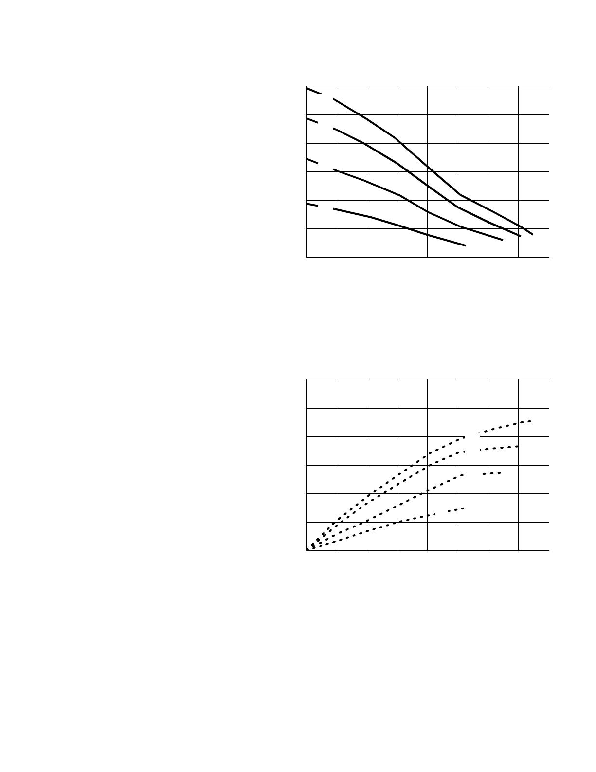
Performance Chart
Test Conditions: Pump tested in water with inlet submerged.
Fluid Pressure Curves
A at 120 psi (0.7 MPa, 7 bar) air pressure
B at 100 psi (0.7 MPa, 7 bar) air pressure
C at 70 psi (0.48 MPa, 4.8 bar) air pressure
D at 40 psi (0.28 MPa, 2.8 bar) air pressure
To find Fluid Outlet Pressure (psi/MPa/bar)
at a specific fluid flow (gpm/lpm) and operating
air pressure (psi/MPa/bar):
1. Locate fluid flow rate along bottom of chart.
2. Follow vertical line up to intersection with
selected fluid outlet pressure curve.
3. Follow left to scale to read fluid outlet
pressure.
120
(0.84, 8.4)
100
(0.7, 7)
80
(0.55, 5.5)
60
(0.41, 4.1)
40
(0.28, 2.8)
20
(0.14, 1.4)
FLUID OUTLET PRESSURE––psi (MPa, bar)
0
0 5 10 15 20 25 30 35 40
A
B
C
D
(38) (133) (152)
(76)
(114)(95)(57)(19)
FLUID FLOW--gpm (lpm)
Air Consumption Curves
A at 120 psi (0.7 MPa, 7 bar) air pressure
B at 100 psi (0.7 MPa, 7 bar) air pressure
C at 70 psi (0.48 MPa, 4.8 bar) air pressure
D at 40 psi (0.28 MPa, 2.8 bar) air pressure
To find Pump Air Consumption (scfm or m#/min)
at a specific fluid flow (gpm/lpm) and air pressure
(psi/MPa/bar):
1. Locate fluid flow rate along bottom of chart.
2. Read vertical line up to intersection with
selected air consumption curve.
3. Follow left to scale to read air consumption.
60
(1.68)
50
(1.40)
40
(1.12)
30
(0.84)
20
(0.56)
10
(0.28)
0
AIR CONSUMPTION––scfm (cubic meters/min)
0 5 10 15 20 25 30 35 40
(38) (133)
A
B
C
D
(95)(57)(19)
FLUID FLOW--gpm (lpm)
(152)(76) (114)
25
Page 26
WARRANTY
Graymills Corporation warrants that the equipment manufactured and
delivered, when properly installed and maintained , shall be free from
defects in workmanship and will function as quoted in the published specification. Graymills does not warrant process performance, nor assume any
liability for equipment selection, adaptation, or installation.
Warranty does not apply to damages or defects caused by shipping, operator carelessness, mis–use, improper application or installation, abnormal
use, use of add–on parts or equipment which damages or impairs the proper function of the unit and modifications made to the unit. Warranty does
not apply to expendable parts needing replacement periodically due to
normal wear and tear.
A new Warranty period shall not be established for repaired or replaced
materials or products. Such items shall remain under Warranty for only the
remainder of the Warranty period of the original materials or product.
THE FOREGOING WARRANTIES ARE IN LIEU OF ALL OTHER
WARRANTIES, WHETHER ORAL, WRITTEN, EXPRESSED, IMPLIED
OR STATUTORY. GRAYMILLS CORPORATION MAKES NO OTH-
ER WARRANTY OF ANY KIND EXPRESS OR IMPLIED. ALL IMPLIED WARRANTIES OF MERCHANTABILITY AND
Graymills Corporation 3705 N. Lincoln Avenue Chicago, Illinois 60613 773/248–6825 FAX 773/477–8673 www.graymills.com
FITNESS FOR A PARTICULAR PURPOSE WHICH EXCEED THE A
FORESTATED OBLIGATION ARE HEREBY DISCLAIMED BY GRAY-
MILLS CORPORATION AND EXCLUDED FROM THIS SALE.
Graymills warranty obligations and Buyer remedies (except to title) are
solely and exclusively stated herein. In no case will Graymills be liable
for consequential damages, loss of production, or any other loss incurred
due to interruption of service.
Graymills’ obligation under this Warranty shall be limited to:
a) Repairing or replacing (at Graymills sole discretion) any non–conforming or defective component within one year from the date of
shipment from Graymills.
b) Repairing or replacing (at Graymills sole discretion), components
supplied by, but not manufactured by Graymills, to the extent of the
warranty given by the original manufacturer.
Buyer must give Graymills prompt notice of any defect or failure.
If you believe that you have a Warranty claim, contact Graymills at
(773)248–6825. Any return material must have an RMA number on the
outside of the package and must be shipped prepaid or shipment will be
refused. Graymills will promptly examine the material and determine if it
is defective and within the Warranty period.
26
 Loading...