

Addendum to Operating Manual
795-09456-C 12-07
for
“Quick Change” PERISTALTIC INK PUMPS and Retrofit Kits to
Convert SPLASH RESISTANT PUMPS to “Quick Change”
SINGLE HEAD PERISTALTIC PUMPS
SAFETY-Do Not operate pump without Pump Head installed on the motor housing. Pump Head must be
properly and securely installed on the pump for safe operation.
CAUTION-
• Pump Head must be fully inserted into the adapter and Retractable Pin must be fully engaged for
pump to operate properly.
• DO NOT pull Retractable Pin while pump is in operation. Stop pump before pulling pin.
• DO NOT attempt to remove, rotate or make any adjustments to Pump Head while pump is in
operation.
WARNING-
• Disconnect power supply to the pump before making any connections, adjustments or performing
service work
• The “Quick Change” Pump has two head sizes: PPS and PPL. The Retrofit Kit must match your pump
head size: Kit C-39598 converts the PPS (Small) to the PQS Quick Change head; and the C-39601
converts the PPL (Large) to the PQL Quick Change head.
The Retrofit Kits to convert Splash Resistant Pumps to “Quick Change” Heads are:
Graymills Part Number C-39598 to Convert Small Pump Heads (PPS) to the “Quick
Change” (PQS) Head;
Graymills Part Number C-39601 to Convert Large Pump Heads (PPL) to the “Quick
Change” (PQL) Head.
NOTE: All users of the “Quick Change” Single Head must first review
OMI #795-09456
for
complete instructions regarding general peristaltic pump safety, operation and installation. All
instructions contained here apply to unique characteristics of the Single Head Peristaltic Ink
Pump only.
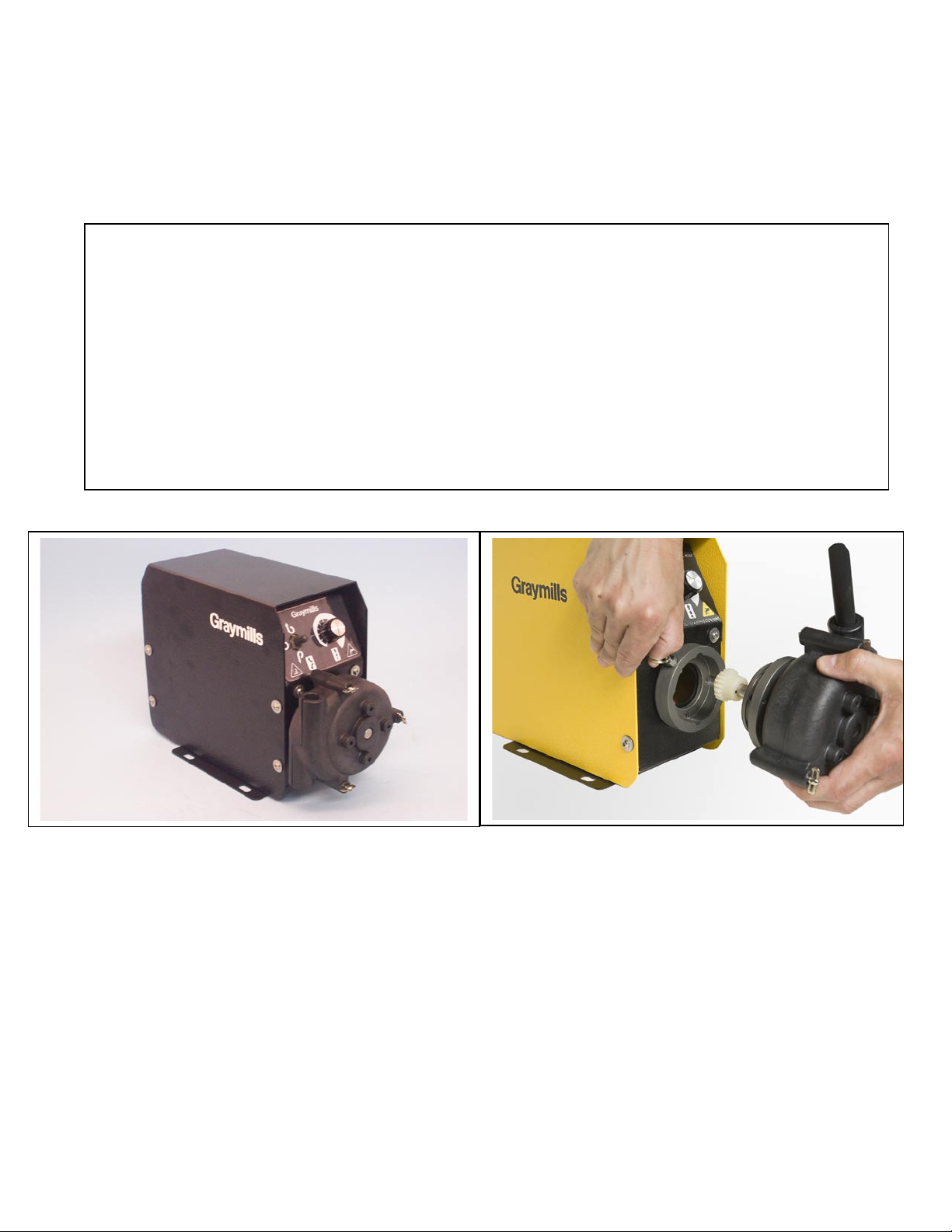
Splash Resistant Peristaltic Pump
“Quick Change” Peristaltic Pump with
Removable Head
ABOUT the Retrofit Kit for “Quick Change” Single Head PERISTALTIC PUMPS
This instruction is intended to be used with two types of Peristaltic Pump-the pump configured as a “Quick
Change” pump as manufactured by Graymills; and the Splash Resistant pump converted to the “Quick
Change” head in the field by use of a Retrofit Kit.
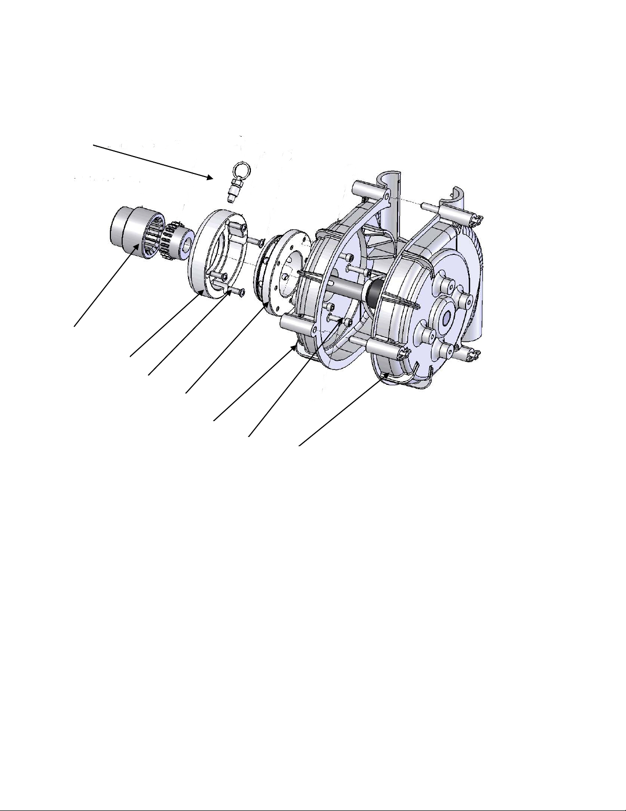
Components of Retrofit Kit for “Quick Change” Peristaltic Pumps
1. Coupling Set
2. Female Adapter(Mounts on Pump Case)
3. Mounting Screws for Female Adapter
4. Male Adapter(Mounts on Pump Head)
5. Pump Head (Inner Half)
6. Mounting Screws for Male Adapter
7. Pump Head (Outer Half)
8. “Quick Release” Retractable Pull Pin
Mounting Instructions for Retrofit Kit
1. Remove Screws from case to expose interior of pump, shaft and coupling.
2. Remove Universal Coupling (between motor and Head Shaft) from Splash Resistant Pump. New
Coupling Set (#1, ABOVE) w i l l be t wo -piece replacement for universal coupling.
3. Install Female Coupling half on motor side shaft with set screw provided; install male Coupling Half on
shaft with Set Screw provided
4. Install Female Adapter (#2, ABOVE) on outside of Pump Case with four screws (#3, ABOVE) provided.
5. Install Male Adapter (#4, ABOVE) on Inside Half of PUMP Head(#5, ABOVE) wi t h four screws (#6,
ABOVE) provided. Outside Half of Pump Head (#7, ABOVE) with hose can now be mated to Inside Half
of Pump Head.
6.
Pump Head can now be installed on Pump Case by pulling retractable pin (#8, ABOVE) and mounting
head on case.
3
2
4
7

PUMP HEAD REMOVAL/INSTALLATION for “Quick Change” pump
Installing or removing a complete Pump Head, Male Adapter and Hose assembly.
Once the retrofit kit is installed on the pump, installation/removal of pump head is the same for both the retrofit and the
factory-built version:
• Stop pump and disconnect power supply.
• Pull Retractable Pin and remove current Pump Head Assembly from motor. The head can be removed with hose in
head, thus speeding changeovers.
• Align pump head with male adapter with female adapter on case. If necessary rotate Pump Head slightly until pump
head mates with adapter.
• Pull Retractable Pin and continue pressing Pump Head assembly into motor to close the gap between two mating
Adapters.
• Rotate and Lock Pump Head as desired.
• Remove pressure from Retractable Pin to allow spring pin to engage with Male Adapter. Rotate and pull on Pump
Head to ensure it is properly secured and will not pull off.
•
Pump Head Assembly is now ready for operation
PUMP HEAD REPLACEMENT
For replacing a cracked or split plastic pump half, please see the instructions in the OMI #795-09456.
Changing Pump Direction
Specifics of switch operation for speed and direction control are in OMI #795-09456.
Fusing for the Quick Change Single Head Model
For 115 and 230VAC pump operation, use two (2) fuses, Part #780-91518 (5 x20mm, 5.0 Amp, 250VAC, Type FST, Slow Blow)
REPLACEMENT PARTS LIST
Description
Small Peristaltic
PQS Head
Large Peristaltic
PQL Head
Replacement Pump Head Only
401-35349-78
401-36347-78
Replacement Head Assembly w/Adapter
401-39597
401-39600
Replacement Head Assembly with M/F Adapter
C-39598
C-39601
Male Adapter (one/head)
539-39187-36
539-39187-36
Female Adapter (one/case)
539-39635-36
539-39604-36
O-Ring replacement kit (12 pieces)
C-37515
C-37514
Hose 3/8” ID x 5/8” OD (50 ft)
729-90598-50
Hose 5/8” ID x 7/8” OD (50 ft)
729-90597-50
Ball Bearings (two/head)
760-09251
760-09256
Coupling Set- ½” Bore
769-09254
Coupling Set- 5/8” Bore
769-09260
Swivel Lock Fastener (three/head)
402-34971
402-34971
Key, 1/8” sq. x 9/16” long.
758-08118-81 (two/head)
Key, 3/16” sq. x 7/8” long.
758-09258 (one/head)
758-09258 (three/head)
Double Barb Fitting- 3/8” x 3/8”
730-09310
Double Barb Fitting- 5/8” x 5/8”
730-09309
Retractable Pin
756-91475
756-91475
© 2006 Graymills Corporation Specifications May Change without Prior Notification
Graymills
3705 N Lincoln Avenue Chicago, IL 60613
773-248-6825 Fax 773-477-8673 www.graymills.com
 Loading...