

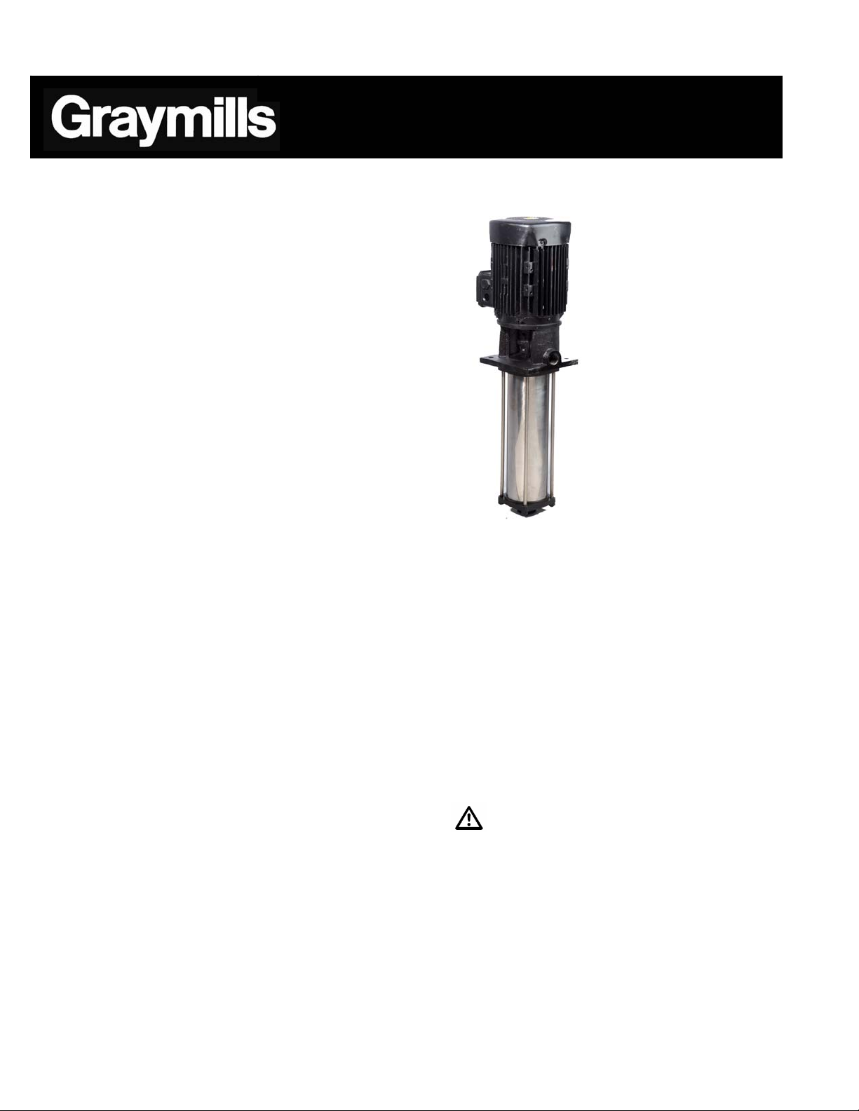
Multi-Stage
Centrifugal
MVP Pumps
Operations and Maintenance
Instructions
WARNINGS/CAUTIONS
Read all these SAFETY INSTRUCTIONS BEFORE
installing or using this equipment. Keep this
manual handy for reference/training.
Inspect unit for damage. Report any damage to
carrier/dealer immediately.
Pump may be heavy. If in doubt, take appropriate
precautions.
Motor must be grounded and suitable for the
environment in which it is used. Do not use where
explosion-proof motors are required.
Do not allow liquids to come into contact with the
motor, or any electrical components.
Never attempt any service work while the unit is
still connected to any electrical power source.
This pump contains rotating parts. Use caution.
When working on or around pump, be aware of
what liquid is/has been pumped. If liquid is
potentially harmful, take appropriate precautions.
Never use any part of the wiring/electrical system
to lift or move the equipment. This could cause a
failure of the electrical system, resulting in severe
shock or death.
Do not operate this pump or allow others to
operate it until the instructions and warnings have
been read and are understood by all involved.
Never work with equipment you feel may be unsafe.
Contact your Supervisor immediately.
DESCRIPTION/SPECIFICATIONS
The Graymills MVP Series pumps are multi-stage
centrifugal pumps designed to handle clean, water and
water-based coolants.
795-91725
3-07
www.graymills.com
Minimum and maximum liquid temperature range: -
0
C to 930C(500F to 2000 )
10
Maximum Air Temperature 40
Maximum viscosity 500 SSU
Maximum On/Off Cycles per hour: 100
Maximum inlet pressure 100 psi.
Pipe connections are 1" NPT for both inlet and
discharge.
Bypass kit is included and should be used for
applications where low flow conditions can exist.
See Installation Section, Page 2.
Rotation: left hand, ie, COUNTERCLOCKWISE
when viewed from motor end.
0
C (1040 F)
POWER SUPPLY, WIRING AND
GROUNDING
WARNING
Install ground and wiring according to local and
National Electrical Code requirements.
Install a disconnect switch on all power legs near
the pump.
Disconnect and lockout electrical supply before
installing or servicing pump.
230/460V, 3 phase, 60 cycle AC circuit rated for a
minimum of 10 amps. Refer to motor nameplate for
instructions.
- 1 -

Electrical supply MUST match pump’s name plate
specifications. Incorrect voltage can cause fire
and/or damage to the motor and voids warranty.
Motor overload protection standard on three-phase
motors.
Use only stranded copper wire to motor and
ground. The ground wire MUST be at least as
large as the wire to the motor. Wires should be
color coded for ease of maintenance.
Follow motor manufacturer’s wiring diagram on the
motor nameplate or terminal cover carefully.
WARNING
Failure to permanently ground the pump, motor
and controls before connecting to electrical power
can cause shock, burns or death.
ROTATION
Incorrect rotation may cause damage to pump in
and will void the warranty.
Correct rotation is left-hand,
COUNTERCLOCKWISE when viewed from the
motor end.
Rotation can be verified by quickly energizing the
pump for an instant with a quick on/off motion.
To reverse three phase motor rotation interchange
any two power supply leads.
PIPING
Piping should be no smaller than the pump
discharge. Piping should be kept as short as
possible, avoiding unnecessary fittings to minimize
friction losses.
All piping MUST be independently supported and
MUST NOT place any piping loads on the pump. It
should “line up” naturally.
All joints MUST be airtight. Use 3 - 4 wraps of
Teflon™ tape to seal threaded connections.
CAUTION
Never draw piping into place by forcing the pump
discharge connections.
Bypass Kit (included)
Figure 1
INSTALLATION
WARNING
Multi-stage pumps produce considerable shut-off
pressure. Hoses and associated plumbing used with
these pumps should be rated for a minimum working
pressure of 350 PSI. Failure to heed this warning could
result in ruptured lines and possible injury to personnel.
Minimum and maximum liquid levels must be
maintained for proper pump operation.
See Figure 1.
Allow adequate space for servicing and ventilation.
Protect from freezing and flooding
The pump must be installed in a ventilated area,
and the ambient temperature must not exceed 40
C (104
Before installation, verify that motor and pump are
rotating well by rotating the motor fan.
0
F)
.
0
- 2 -
WARNING
Graymills recommends the use of an inlet strainer
to minimize the size and amount of debris that
enters the pump. Contamination drawn into the
pump can cause internal damage and is not
covered under warranty. Consult factory for
recommendations as to the appropriate size and
type of strainer to use.

High Pressure Filters for keeping fluid clean should
be used. Graymills can provide a filter to trap
particles, scale and contaminants to prevent costly
damage. Filter collects up to 20 cu. in. of material
(HPFB20) without pressure drop. Available in 14"
length single cartridge model (HPFB10) or 24"
length dual cartridge model (HPFB20). All models
are 304 stainless steel for use with water-soluble
and corrosive liquids. Reusable stainless steel
cartridges available in 10, 50, and 100 mesh.
OPERATION
CAUTION
Before starting, pump must be primed (free of air) and
discharge valves partially open.
Do not run pump dry; damage to mechanical seal
will result.
Use a Check valve on plumbing if pump is
mounted horizontally or if the potential to lose
prime can occur.
On-Off Cycling must be limited to under 100 times
per hour, because excessive starting cycles may
harm the windings of the motor.
Do not run against closed nozzles or damage to
pump and piping will result. Use Bypass as
described below.
Do not operate at or near zero flow.
If operating at or below 8 gpm or where valves may
be opened and closed periodically, you must use a
bypass. This kit (Bypass Kit C-39695),See Figure
1, installs in the side of the discharge head and
provides a fluid bypass when the pump is operated
against a closed discharge thus preventing
excessive heat build-up which will damage the
pump.
After stabilizing the system at normal operating
conditions, check the piping. If necessary, adjust
the pipe supports.
To ensure proper suction, fluid level should cover
first two impellers (5" from the suction end of the
pump). See Figure 1.
Pump may be mounted horizontally with optional
horizontal mounting bracket. However, care must
be taken to ensure that prime is not lost.
If pump is not generating enough pressure or flow,
see “TROUBLESHOOTING GUIDE”.
MAINTENANCE
WARNING
Failure to disconnect and lockout electrical power
before attempting any maintenance can cause shock,
burns or death.
Motors have permanently lubricated bearings. No
lubrication is possible or necessary.
Depending upon conditions and operating time, it
is important to perform regular inspections of the
pump. Items to inspect are as follows:
o Performance-Head, Pressure and
Flow
o Noise Level and Leakage
o Filter Cleanliness
The mechanical seal used is cooled and lubricated
using liquid within the pump. Separate lubrication
is unnecessary
To REMOVE pump from service, drain all fluid
from pump and piping.
To RETURN pump to service, replace all plugs and
piping using Teflon™ tape or equivalent on male
threads.
Disassembly
In most cases, the only maintenance necessary will be
replacement of the mechanical seal on the shaft. The
procedure below describes the process of
disassembling the pump’s stages to replace the seal.
Remove stay bolts on outside of pump column by
removing nuts on bottom end of bolts. Bolts can
then be unscrewed from motor bracket.
Remove suction cover from bottom of pump.
Remove O-Ring and Outer Chamber Sleeve. The
sleeve may need to be tapped and rotated to break
if free from the motor housing. There is an O-Ring
on both top and bottom of Outer Chamber Sleeve.
Inspect both after removal and replace if they show
signs of deterioration.
Remove nut and lock washer from shaft. The nut
has a left-hand thread to prevent loosening during
rotation of the pump. Each stage is a two-piece
construction of impeller and bowl/diffuser. The first
stage after the suction head will have a special
seal. During re-assembly make sure it occupies the
same position. The procedure should be the same
regardless of the number of stages in your pump.
Each stage is removed in the same manner as the
first. A screwdriver blade and application of mild
force might be needed to separate the sections.
DO NOT DEFORM OR BEND THE STAGES. Note
carefully the system of spacers. Each stage has a
spacer that prevents the impeller from contacting
the bowl/diffuser.
Once the stages have been removed, take the
circlip below the mechanical seal off the shaft.
Slide the seal off the shaft. Examine the seal for
damage or wear. If necessary, replace the seal.
If necessary to remove entire shaft from pump, it
will require the coupling guard, coupling and pin to
be removed. Remove the two fasteners that hold
the guard in place. Remove the four Allen-head
- 3 -

bolts, two on each side, from the coupling. The
shaft pin should then be accessible and the shaft
can be removed from the pump.
The seal face is pressed into the pump housing.
Inspect for damage. If necessary replace by prying
out with a screwdriver. Inspect O-Ring that
surrounds seal face. Replace O-Ring if damaged.
Replace seal face by pressing in a new face in the
housing.
Reassembly
With new seal face installed in housing, replace shaft
and pin and secure coupling with four Allen-head bolts.
Replace coupling guard and screws.
Replace mechanical seal on shaft. Replace circlip
on shaft below seal.
Reinstall stages in the reverse order of removal.
Stages should not be warped, bent or damaged.
Note carefully how spacers are used to prevent
impeller from contacting the bowl/diffuser. Replace
nut and lock washer on shaft to retain stages.
Replace O-Ring in pump housing and fit
intermediate chamber sleeve into pump housing.
Install stay bolts into motor casing. Place O-Ring
into suction cover and place suction cover over
intermediate chamber cover. Thread nuts onto end
of stay bolts and tighten to retain suction cover.
Troubleshooting Guide
Problem Probable Cause
Pump Head Leakage
Leakage between pump body, upper cover and/or casing Damaged O-ring, replace the O-Ring
Mechanical Seal Wear; replace Mechanical Seal
Low power during output during peak Overload protector frequently trips during operation
Unstable voltage supply
Odd noise and vibration
Water is not coming out
Pump is operating, but not normally
Pump cavitation
Damaged motor bearing
Pump and piping not anchored properly
Pump not primed properly
Excessive head requirement from too much piping
Check for restrictions in plumbing
Release air from, or reconfigure intake pipe
Clean out clogged impeller
Check motor rotation to verify if pump is operating
properly
- 4 -
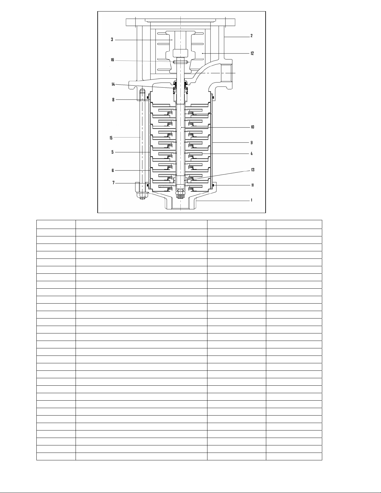
Replacement Parts
Ref Description Material Part Number
1 Suction Cover Stainless Steel 793-91748
2 Motor Bracket Gray Cast Iron 793-91749
3 Coupling Gray Cast Iron 793-91750
4 Impeller Stainless Steel 793-91751
5 Intermediate Chamber Stainless Steel 793-91752
6 Intermediate Chamber with Bearing Stainless Steel 793-91753
7 Intermediate Chamber without guide vane Stainless Steel 793-91754
8 Intermediate Chamber without neck ring Stainless Steel 793-91755
9 Outer Sleeve-MVP4(95mm) Stainless Steel 793-91727
9 Outer Sleeve-MVP6(135mm) Stainless Steel 793-91728
9 Outer Sleeve-MVP8 (175mm) Stainless Steel 793-91729
9 Outer Sleeve-MVP12 (255mm) Stainless Steel 793-91730
9 Outer Sleeve-MVP16 (335mm) Stainless Steel 793-91731
9 Outer Sleeve-MVP20 (415mm) Stainless Steel 793-91732
10 Shaft-MVP4 Stainless Steel 793-91733
10 Shaft-MVP6 Stainless Steel 793-91734
10 Shaft-MVP8 Stainless Steel 793-91735
10 Shaft-MVP12 Stainless Steel 793-91736
10 Shaft-MVP16 Stainless Steel 793-91737
10 Shaft-MVP20 Stainless Steel 793-91738
11 O-Ring Viton 793-91756
12 Coupling Guard Stainless Steel 793-91757
13 Bearing sleeve Tungsten Carbide 793-91758
14 Mechanical Seal Viton 793-91759
15 Stay Bolt-MVP4 Stainless Steel 793-91763
15 Stay Bollt-MVP6 Stainless Steel 793-91764
15 Stay Bolt-MVP8 Stainless Steel 793-91765
15 Stay Bolt-MVP12 Stainless Steel 793-91766
15 Stay Bolt-MVP16 Stainless Steel 793-91767
15 Stay Bolt-MVP20 Stainless Steel 793-91768
16 Coupling Pin Stainless Steel 793-91762
- 5 -

WARRANTY
Graymills Corporation warrants that the equipment
manufactured and delivered hereunder when properly
installed and maintained, shall be free from defects in
workmanship.This warranty does not apply to damages
or defects caused by operator carelessness, misuse,
abuse, improper application, or abnormal use; the use
of add-on parts or equipment which damages or
impairs the proper function of the unit and
modifications made by Buyer. Graymills’ obligation
under this Warranty shall be limited to: 1. Replacing or
repairing tank and structural parts within one year from
the date of installation or 13 months from the date of
shipment whichever occurs first. The decision to
replace rather than repair shall be made by Graymills
Corporation; 2. Replacing or repairing components
supplied but not manufactured by Graymills, such as
pneumatic cylinders, controls, pneumatic systems,
motors, heater controls and heaters to the extent such
components are warranted by the original
manufacturer’s warranty, provided that Buyer gives
Graymills prompt notice of any defect or failure and
satisfactory proof thereof. Before Graymills can repair
or replace a defective part under warranty, call
Graymills for a Return Merchandise Authorization
number (RMA number must appear on outside English
of package or it will be refused and returned). Upon
prepaid return to Graymills’ factory, Graymills’
examination must disclose such part to be defective.
This warranty does not apply to expendable parts such
as rollers, bearings, cylinder packings and any other
parts which need replacement periodically due to
normal wear nor to rusting of a mild steel heated unit
used with aqueous (water) based cleaning solutions. A
new warranty period shall not be established for
repaired or replaced materials, or products. Such items
shall remain under warranty for only the remainder of
the warranty period of the original materials or
products.
Graymills warrants that the equipment will function
mechanically as quoted in the published specification.
Graymills does not warrant process performance nor
does Graymills assume liability for equipment
selection, adaption or installation. The foregoing
warranties are in lieu of all other warranties whether
oral, written, expressed, implied or statutory. Implied
warranties of fitness for a particular purpose and
merchantability shall not apply. Graymills’ warranty
obligations and Buyer’s remedies thereunder (except
as to title) are solely and exclusively as stated herein.
In no case will Graymills be liable for consequential
damages, loss of production or any other loss incurred
because of interruption of service.
Graymills® 3705 N. Lincoln Ave. Chicago, IL 60613 773-248-6825 1-888-GRAYMILLS
www.graymills.com ©2007 Graymills Corporation
Specifications may change without notice
- 6 -
 Loading...