

Graymills Liftkleen L-Series User Manual
795-90716
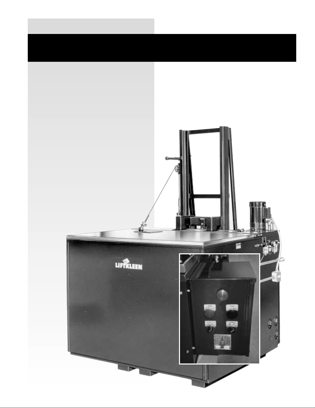
NEW
CONTROL
PANEL
GM 11-07
L-SERIES LIFTKLEEN
®
PARTS CLEANERS –
AQUEOUS/SOLVENT
Operations and Maintenance
Instructions

WARNINGS/CAUTIONS . . . . . . . . . . . . . . . . . . .2
INTRODUCTION . . . . . . . . . . . . . . . . . . . . . . . . .4
LIFTKLEEN CONSTRUCTION FEATURES . . . .4
TANK ASSEMBLY . . . . . . . . . . . . . . . . . . . .4
PLATFORM AND LIFTER ASSEMBLY . . . .4
SUPERFLO PUMPASSEMBLY . . . . . . . . .4
COVER ASSEMBLY . . . . . . . . . . . . . . . . . .5
CONTROLS - PNEUMATIC and
ELECTRIC . . . . . . . . . . . . . . . . . . . . . . . . . .5
INSTALLATION OF THE LIFTKLEEN . . . . . . . .6
SERVICE HOOK-UP . . . . . . . . . . . . . . . . . .6
FLOOR MOUNTING OF LIFTKLEEN . . . . .6
OPERATION OF THE LIFTKLEEN . . . . . . . . . . .6
AGITATING LIFT PLATFORM . . . . . . . . . . .6
CYCLE TIMER (optional) . . . . . . . . . . . . . . .7
EMERGENCY STOP . . . . . . . . . . . . . . . . . .7
ANTI-TIE DOWN DEVICE (optional) . . . . . .7
SUPERFLO PUMP (optional) . . . . . . . . . . .7
ELECTRIC HEAT (optional) . . . . . . . . . . . . .7
STEAM HEAT (optional) . . . . . . . . . . . . . . .7
HEATER TIMER (optional) . . . . . . . . . . . . . .7
FILTRATION SYSTEMS (optional) . . . . . . .7
LIFT PLATFORM MOTION
ADJUSTMENTS . . . . . . . . . . . . . . . . . . . . . .8
SUPERFLO PUMP DISCHARGE
DIRECTION ADJUSTMENTS . . . . . . . . . . .8
MAINTENANCE . . . . . . . . . . . . . . . . . . . . . . . . .8
LOCK OUT PROCEDURES . . . . . . . . . . . .8
LUBRICATION . . . . . . . . . . . . . . . . . . . . . . .8
PNEUMATIC SYSTEM . . . . . . . . . . . . . . . .8
TROUBLESHOOTING GUIDE . . . . . . . . . . . . . .9
TABLES
1 DIMENSIONS/SPECIFICATIONS . . . . .12
2 PLATFORM LOAD CAPACITY . . . . . . .13
3 AIR CONSUMPTION DATA . . . . . . . . . .13
4 ELECTRICAL CURRENT
REQUIREMENTS . . . . . . . . . . . . . . . . .14
5 LIFTKLEEN FILTERS . . . . . . . . . . . . . .14
REPLACEMENT PARTS
PNEUMATIC, ELECTRICAL AND HEATING
COMPONENTS . . . . . . . . . . . . . . . . . . . . .15
PUMPASSEMBLY . . . . . . . . . . . . . . . . . .16
AIR CYLINDERS . . . . . . . . . . . . . . . . . . . .16
MISC. MECHANICAL PARTS . . . . . . . . . .16
FIGURES
1 BASIC ASSEMBLY LKR & LKD
(SIDE, TOP) . . . . . . . . . . . . . . . . . . . . . .17
2 BASIC ASSEMBLY LKR & LKD
(SIDE) . . . . . . . . . . . . . . . . . . . . . . . . . .17
3 ELECTRICAL SCHEMATICS . . . . . . . . .18
4a, b, c PNEUMATIC SYSTEMS . . . . . . .19
4d ANTI-TIE DOWN SYSTEMS . . . . . . . . .22
5A, B LKT-4 CYCLE TIMER . . . . . . . . . . .23
6 MANUALLYOPENED COVER . . . . . . .24
7 CYLINDER OPERATED COVER . . . . . .25
8 VALVE CONNECTIONS . . . . . . . . . . . .26
9a, b FLOOR MOUNTING HOLE
LOCATIONS . . . . . . . . . . . . . . . . . . . . .27
10 OPERATING SWITCHES . . . . . . . . . .27
11 TEMPERATURE DIAL . . . . . . . . . . . . .27
12 HEATUPTIME CHART . . . . . . . . . . . .28
13 SPEED CONTROL . . . . . . . . . . . . . . .29
14 MASTER ON/OFF VALVE and
AIR FILTER/REGULATOR/
LUBRICATOR . . . . . . . . . . . . . . . . . . .29
15 AIR LINE CONNECTION . . . . . . . . . . .29
16 PUMP ASSEMBLY . . . . . . . . . . . . . . . .30
17 SUPERFLO PUMP DISCHARGE
NOZZLE . . . . . . . . . . . . . . . . . . . . . . . .30
18 LUBRICATION POINTS . . . . . . . . . . . .31
19 STEAM HEATING ARRANGEMENT . .31
20 LKF-100 FILTRATION SYSTEM . . . . .32
21 LKF-22 FILTRATION SYSTEM . . . . . .32
22 PNEUMATIC TUBING CONNECT/
DISCONNECT . . . . . . . . . . . . . . . . . . .33
23 “DOWN” AIR POWER DISCONNECT .33
WARRANTY . . . . . . . . . . . . . . . . . . . . . . . . . .34
1
L-SERIES LIFTKLEEN
TABLE OF CONTENTS

WARNINGS/CAUTIONS
Read all of these SAFETY INSTRUCTIONS and
those in the manual BEFORE installing or
using this equipment. Keep this manual handy
for reference/training.
SAFETY
You will find various types of safety information on
the following pages and on the labels attached to
Graymills equipment. The following Safety
Statements explain their meaning:
The Safety Alert Symbol means ATTENTION!
BECOME ALERT! YOUR SAFETY IS
INVOLVED!
DANGER The DANGER Symbol means that
failure to follow this safety statement will result
in serious personal injury or death.
WARNING The WARNING Symbol means
that failure to follow this safety statement
might result in serious personal injury or
death.
CAUTION The CAUTION Symbol means
that failure to follow this safety statement
might result in personal injury or property
damage.
NOTE The NOTE Symbol means failure to
follow these instructions could cause damage
to the equipment or cause it to operate
improperly.
CAUTION
Never work with equipment you feel may be
unsafe. Contact your Supervisor immediately
if you feel a piece of equipment is in an unsafe
condition.
HEATED MACHINES ONLY –
AQUEOUS
• This is a heated parts cleaner.
WARNING
Use only nonflammable, non-combustible,
water-based alkaline cleaning compounds.
Graymills recommends Super Aquatene
®
330
or 360 (General Purpose), Aquatene
®
581
(General Purpose and Non-Ferrous Metals),
Aquatene®571 (Ferrous Metals Only), Low
Foam GM390 or pH neutral, non-corrosive
Super Biotene
®
GM550.
!!!!!!!
If you have any questions regarding the
correct fluids to use in this unit, call Graymills
at (773) 248-6825 and ask for Customer
Service.
Do NOT fill with or contaminate cleaning fluid
with any flammable or combustible material
such as gasoline, alcohol, mineral spirits, etc.
Drain parts to be cleaned of any flammable or
combustible material before placing inside
cleaning tank. Even small quantities can
create a dangerous fire hazard.
Follow all directions, Warnings, Cautions and
Dangers for the cleaning material being used.
CAUTION
When making an initial batch of cleaning
solution or when adding compound to a
heated Liftkleen, follow manufacturer’s
directions exactly. Wear appropriate safety
equipment as recommended. Add only small
amounts at one time to prevent a sudden
boiling and/or eruption of liquid which will create a hazardous condition. NEVER dump in a
large quantity at one time.
WARNING
Maximum operating temperature is 180°F.
Higher temperatures will cause increased risk
of personal injury and damage the unit.
Remember, any temperature above 115°F can
cause severe burns. Equipment itself will be
hot. Use caution.
The operator and anyone working in or around
the Liftkleen must be cautious of the hot tank
contents (cleaning solution, platform, lid being
closed, etc.) and of the steam which escapes
when the lid is opened. Be sure everyone who
works in or around the Liftkleen reads and
understands how to use the chemicals or compounds being used, as well as the machine.
NOTE
Turn heater off when unit is to be idle for extended
periods (overnight or weekends). Liquid could
evaporate enough to damage heater coil.
CAUTION
Pump intake is above heater coil. If solution
does not circulate, liquid level is too low. Turn
heater (an optional feature) and pump (an
optional feature) off immediately. Failure to
keep coil immersed can cause heater to burn
out.
!!!
2

HEATED AND UNHEATED
MACHINES –
AQUEOUS/SOLVENT
WARNING
These units have moving parts, pinch-points
and close tolerances. Always stand clear of lift
platform and lid when operating as the lid
could unexpectedly open or the platform
operate. Never raise lift platform with lid
closed. Keep hands and fingers away from
tank when operating platform. (See the
OPERATION section.)
Unit must be properly grounded to prevent
electric shock hazard. Connect only to three
prong outlet. Should cord become cracked,
frayed or damaged in any way, it should be
repaired immediately by a qualified electrician.
Never use an extension cord.
Since operator safety at all times is a priority,
we strongly recommend that, whether or not
required by local code, this equipment be
connected only into a power supply equipped
with a “Ground Fault Interrupter” (GFI). All
electrical connections should conform to
national/local codes and be made by qualified
personnel.
CAUTION
Inspect optional pump, optional heater and all
electrical cords, plugs, and fusible link each
time unit is cleaned. Do NOT use if any wear or
damage is noticed until impaired components
are repaired or replaced. Never operate if
fusible fire link is not in place and functional.
Fill tank to recommended operating capacity
range before plugging in power cord. (See
Table 1, p. 12.)
WARNING
DO NOT perform any maintenance work on
Liftkleen without having the air shut-off valve
in the “Off” position and main air lines to
cylinders disconnected. Disconnect electrical
power. Follow lock out procedures.
CAUTION
If any cleaning solutions are splashed on
clothing, remove wet clothing promptly and
thoroughly wash body areas that have been in
contact with the solution. Do NOT permit
saturated clothing to remain in contact with
skin. Consult manufacturer’s Material Safety
Data Sheet (MSDS).
!
!
!
!
NOTE
If you have purchased a heated unit with a carbon
steel tank, observe the following before using:
Water-based cleaning materials will generate
steam and water vapors. Surfaces above the liquid
level will be subject to rusting (this condition exists
with any manufacturer’s unit). This is primarily surface rust and does not appreciably affect the
serviceability of the unit. However, if your cleaning
requirements cannot tolerate any rust or
contamination, please contact the factory for
information on stainless steel models before
putting the unit into service. Also, be sure your
cleaning material contains a rust inhibitor. (Check
with your cleaning fluid supplier.) The Graymills
Warranty does not cover rusting of carbon steel
units used with water-based material.
UNHEATED MACHINES –
SOLVENT
WARNING
Do NOT install near open flames or heat. Do
NOT smoke near parts cleaner.
Be sure to follow label instructions provided
with any fluid used in this unit. Use only
combustible fluids with a flash point of 104°F
or higher. Graymills recommends Super or
Regular Agitene
®
(flashpoint approx. 105°F). Do
NOT use flammable materials such as gasoline
or alcohol(under 100°F flashpoint). Use of such
unauthorized materials can cause a health and
safety hazard which might result in serious personal injury or death. If you have any questions
regarding the correct fluids to use in this unit,
call Graymills at (773) 248-6825 and ask for
Customer Service.
Do NOT contaminate cleaning compounds
with any flammable materials (less than 100°F
flashpoint), such as gasoline, alcohol, etc.
Drain parts to be cleaned of any flammable
material before placing inside cleaning tank.
Even small quantities can create a dangerous
safety hazard.
CAUTION
Unit is equipped with a fusible safety link
cover mechanism designed to support the
open lid at a slightly forward angle. In the
event of a fire, the fusible link will melt at 165°F
permitting the lid to slam shut, reducing
oxygen supply to the fire.
!
!
3

Cleaning solutions may irritate skin and eyes.
If splashed in eyes, flush thoroughly with
water with lids open. Consult Material Safety
Data Sheet (MSDS) and a physician. Always
wear appropriate safety items such as gloves,
apron, safety glasses or goggles.
CAUTION
When cleaning, be sure parts are fully drained
of any flammable or corrosive materials. Even
small amounts could cause a hazardous
situation.
All Liftkleen models are shipped pre-wired and
need only be connected to the proper
electrical supply (see nameplate for electrical
requirements). This is the responsibility of the
customer and should be done by qualified personnel. Graymills is not
responsible for any
damage caused by incorrect supply wiring.
Tanks should be cleaned out on a regular
basis to prevent sludge from building up
around heaters. Failure to do so could result in
damage to the heaters. Graymills is not
responsible for such damage.
INTRODUCTION
The Graymills Liftkleen is a heavy-duty multifunction, commercial type parts cleaner designed
for both industrial and automotive applications. It
is available for use with either heated aqueous or
solvent cleaning solutions. Seven basic tank sizes
are offered ranging from 170 gallon capacity to
667 gallons in capacity (see Table 1 for
dimensional data). Apneumatic lift platform is
provided on all models.
A number of optional features are available to
tailor the unit to a specific cleaning application.
• Superflo Pumping Unit with an output of up to
10,000 gallons per hour.
• Filtration system for the cleaning solution.
• Roller conveyor platform (instead of standard
grate), loading and unloading conveyors.
• Cleaning cycle and heater timers.
• Anti-Tie Down Device
• Three 4.5 KW electric, immersion type
heaters and insulated tank depending on
model.
• Steam heat
!
CONSTRUCTION FEATURES
The general arrangements of the Models LKR and
LKD Liftkleen assemblies, including optional
features, are shown in Figures 1 and 2. The
following paragraphs describe specific
construction details.
• TANK ASSEMBLY
The Liftkleen was designed to withstand the
rugged demands of heavy-duty industrial and
automotive parts cleaning. The tank is leaktested after welding. The bottom of the tank
utilizes double wall construction and is
supported by four channels. Openings are
provided to facilitate moving the Liftkleen with
a fork-lift truck. A1-1/2” NPT drain is located
in the bottom of the tank to which permanent
drain connections can be attached. An
overflow port is part of the tank assembly and
is intended for use with heated models only.
A water fill port is located in the rear of the
tank (see Figure 8) and consists of 3/4” NPT
pipe nipple. On optional heated models, the
tank sides and cover are insulated with 1”
thick polystyrene foam (equal to two-plus
inches of fiberglass).
• PLATFORM AND LIFTER ASSEMBLY
The Platform and Lifter Assembly are
designed to handle loads specified for the
particular model of Liftkleen (see Table 2).
The platform consists of an angle iron frame
which supports an open steel grate. The lifter
assembly is made up of a channel weldment,
platform support weldment, four support
rollers with needle bearings and hardened
shafts, and a pneumatic cylinder. (Air
consumption data can be found in Table 3).
The rollers and bearings on all Model LKR
and LKD units are located outside the tank
and therefore never immersed in the cleaning
solution. This helps keep moving parts
lubricated. The standard open steel grate of
the platform assembly can be replaced with
the optional roller conveyor platform.
• PUMP ASSEMBLY
The Superflo Pumping Unit Assembly, an
available option on all Model LKR and LKD
units, is capable of providing 10,000 gallons
per hour of flow and provides exceptional
liquid agitation for quicker, more effective
parts cleaning. It is especially effective on
parts containing holes. The pump is a
centrifugal unit and is driven by an electric
motor.
4

• COVER ASSEMBL Y
The internal cover is made of stainless steel
to eliminate corrosion caused by vapor
condensation. On heated models, opening
and closing the lid is accomplished manually
utilizing a counter balanced lid (Figure 6). An
optional pneumatically powered lid is
available on heated units (Figure 7). Lids, as
well as tanks, are insulated on heated units.
Unheated units must be ordered with a
pneumatically powered lid (Figure 7). The lid
actuation system on these units contains a
temperature sensitive automatic closing
feature. In the event of a fire in the tank, the
platform assembly lowers and the lid closes
automatically.
WARNING
Always stand clear of lid. To prevent injury,
keep head, hands and body clear of the lid, lift
platform and lift mechanism at all times. These
units have moving parts, pinch-points and
close tolerances. Always stand clear of the lift
platform and lid when operating as the lid
could unexpectedly open or the platform
operate. Keep hands and fingers away from
tank when operating platform.
CAUTION
When turning air on or off or when operating
the lift platform, stay clear of the lid, lift
platform and operating mechanism as the lid
could unexpectedly open or the platform
operate.
• PNEUMATIC CONTROLS
The standard Liftkleen is furnished with a
pneumatic system that raises and lowers the
platform, a master on/off valve and a
filter/regulator/ lubricator unit.
The agitating lift platform contains air
controls that agitate the platform up and
down through a range of five inches with a
variable frequency of 20 to 40 strokes per
minute. Stroke frequency depends on load
and available air pressure. Adjustments to
the system should be made under operating
load conditions.
The platform agitation system consists of a
control box with a 2-position oscillation
switch, a start and a restart switch, a master
on/off valve, a filter/regulator/lubricator unit, a
pilot operated directional control valve and
two limit valves.
!
!
The optional pneumatically opened lid control
is incorporated with the platform agitation
system.
Schematics and operation sequence sheets
are presented in Figures 4a through 4c.
All pneumatic tubing connections are made
with Instant Fittings. These make it possible
to connect and disconnect the tubing to the
fittings without the use of a wrench. To
disconnect a tube, simply push in the brass
or plastic collet with a screwdriver tip and pull
the tube from the socket. To engage the tube,
push it into the fitting until it hits the stop.
Sealing of the connection is achieved with an
O-Ring in the fitting. This procedure is shown
in detail in Figure 22.
The air cylinder for raising, lowering and
oscillating (agitating) the work platform has
pneumatic lines connected to both its “up”
and “down” ports. This provides for smooth,
positive, controlled motion in both travel
directions with minimal dependence on the
weight of the work load.
• ELECTRIC CONTROLS
Electrical controls are required on all units
which have pumps, electric heat or steam
heat. Models equipped with optional Superflo
pump assemblies come equipped with a
manual motor starter and thermal overload
protection. Electrically heated models are
equipped with from one to four stainless steel
4.5 KW electric, immersion-type heaters, a
thermostat and contactor. Refer to Table 4 for
the amperage requirements of Liftkleen
Electric Heaters and Pump Motors.
Insulation is added to the tank sides and top
on all heated models. This insulation consists
of one inch thick polyurethane foam.
5

INSTALLATION OF THE
LIFTKLEEN
• SERVICE HOOK-UP
AIR
Units are supplied with a Lockable Air Switch
connection. Connect an air supply line to the
inlet of the master on/off valve located on the
side of the machine (see Figure 14). The
recommended air piping arrangement should
be followed to assure trouble-free operation
(see Figure 15). Once your line is connected,
make sure the air switch sleeve is fully
engaged to ensure proper air supply.
Note: The minimum operating air pressure is
85 PSI, however, operating at this pressure
greatly reduces the lift capacity of the unit.
We recommend operating the unit at 90-100
PSI for optimal performance. Maximum inlet
pressure is 110 PSI. A pressure gauge is
provided on the filter/regulator/lubricator
which is located on the side of the Liftkleen
washer next to the Air Switch Connection.
ELECTRIC
• On Liftkleen models with Superflo Pump
Assembly only, a junction box is provided
on the side of the unit for hook-up with the
appropriate electrical service.
• On Liftkleen models with electric heat
only, an electrical enclosure is provided.
The attachment points on the contactor are
appropriately marked.
• On Liftkleen models with both Superflo
Pump Assembly and electric heat, an
electrical enclosure containing a contactor
is provided. Connections on the contactor
are appropriately marked.
WARNING
The Liftkleen must be properly grounded.
CAUTION
Check the electrical specifications on the
nameplate to assure the proper connections.
On 3 phase models equipped with a Superflo
pump, make sure that the motor rotation is
correct; that is, counter clockwise when
viewed from the top. To reverse rotation,
switch any two of the 3 phase leads.
DRAIN – A1-1/2˝ NPT female drain is
located on the bottom of the tank assembly. A
plug is installed at the factory. To make
connections to the drain, remove the plug
!
!
and install appropriate plumbing. It is
suggested that a shut-off valve be installed.
WATER SUPPLY – A 3/4˝ NPT pipe nipple is
furnished at the rear of the Liftkleen as
shown on Figure 8. This is intended as a connection to a water source for filling tank or
make up supply for heated Liftkleen models.
• FLOOR MOUNTING OF LIFTKLEEN
Four (4) mounting holes for anchoring the
Models LKR and LKD Liftkleen to the floor
are located in the bottom of the channel
weldment assembly at the rear of the
machine (see Figures 9a,b). These holes
accommodate 1/2˝ diameter bolts. The
machine must be anchored to the floor at
these points. Failure to adequately anchor
the unit will affect its lifting capacity and/or
cause structural damage to the machine.
OPERATION
WARNING
Always stand clear of lid. To prevent injury,
keep head, hands and body clear of the lid, lift
platform and lift mechanism at all times. These
units have moving parts, pinch-points and
close tolerances. Always stand clear of the lift
platform and lid when operating as the lid
could unexpectedly open or the platform
operate. Keep hands and fingers away from
tank when operating platform.
• AGITATING LIFT PLATFORM
To operate the unit, first open the lid. On units
equipped with the pneumatically operated
lid, this is done automatically during the next
step. Press the "RESET" button. The
platform will rise to the top of the unit and is
now ready for loading. Please note, the
platform will not rise until the lid is fully open.
Once loaded, rotate the Oscillate Selector
Switch to the "ON" position. Press the
"START" button. Platform will descend to
down position and remain there until lid is
closed. Upon lid closure, the platform will
begin to oscillate and will continue to do so
until the operator depresses the "RESET"
button or rotates the Oscillate Selector
Switch to the "OFF" position. Be sure to open
lid when resetting platform. The platform will
not oscillate unless lid is closed. Those units
equipped with a pneumatically operated lid
will close automatically. If soaking is desired,
!
6

rotate the Oscillate Selector Switch to the
"OFF" position. Once the "START" button is
pressed, the unit will lower and stop in the
fully down position and will remain idle until
the operator depresses the "RESET" button
or rotates the Oscillate Selector Switch to the
"ON" position.
• CYCLE TIMER (OPTIONAL)
This option allows the operator to set the
length of time of the cleaning cycle. To
actuate the timer, turn the Timer Selector
Switch to the "On" position. Set the timer to
the desired cycle time, depress the "Start"
button to begin the sequence. The platform
will agitate for the preset time after which it
will rise along with the lid to an Up/Open
position for the start of the next cycle. Turn
Timer Selector Switch to the "Off" position
when manual operation is desired.
Note: The Cycle Timer is only available on
units with automatically operated lids.
(LKR & LKD units)
• EMERGENCY STOP
The unit includes an E-Stop feature which will
shut down all pneumatic operation when
depressed and should be used in emergency
situations only. Once the obstruction/problem
is corrected the switch can be reset by simply
lifting the button back into its original position.
• ANTI-TIE DOWN DEVICE (OPTIONAL)
This device protects the operator from
potential situations where contact with a
pinch point on the machine can occur. The
function of this device replaces the "START"
button in the preceding sequence instructions
and will require the operator to depress two
buttons simultaneously and hold them until
the lid is resting in the closed position. The
unit will then function normally as described
in the previous operational instructions.
• SUPERFLO PUMP (OPTIONAL)
A manual starter is provided to enable the
operator to turn the pump on when pump agitation is desired. If the optional filtration
system is selected, the pump must be
operated to create the filtration process. The
general arrangement of a pump assembly is
shown in Figure 16. For wiring schematic,
see Figure 3.
• ELECTRIC HEAT (OPTIONAL, AQUEOUS
UNITS ONLY)
Heaters are automatically turned on and off
by the thermostat (Figure 11) to maintain the
desired tank temperature. The thermostat is
adjusted by rotating the dial over its indicated
range of 60°F to 180°F. The heaters can be
shut off by setting the thermostat to the “Off”
position. Figure 12 contains data regarding
heat-up time for the various Liftkleen models.
For wiring schematic, see Figure 3.
Operating temperature should not exceed
180°F.
Note: Never operate heaters unless they are
completely covered by liquid.
• STEAM HEAT (OPTIONAL)
Liftkleens are available with optional steam
heat. This option comes complete with a thermostat and all necessary plumbing and
requires the hook-up of the steam supply and
condensate lines along with the connection of
a 115V electrical supply to the thermostat.
• HEATER TIMER (OPTIONAL)
The LKT-1 Heater Timer is available on all
heated Liftkleen units. This option allows the
operator to preset both the heater startup
time and the length of time the heater is in
operation each day. The timer also features a
“day skipper” feature which allows the unit to
remain off on weekends, lowering heating
costs.
• LIFTKLEEN FILTRATION SYSTEMS
(OPTIONAL)
Filtration systems are available on all
Liftkleen models featuring pump agitation.
The system consists of standard, single or
dual filters and a selection of filter elements.
Model LKF-100 (Figure 20) is a single
cartridge filter. Model LKF-22 (Figure 21) is a
dual cartridge unit. Model LKF-100 is
equipped with a 100 mesh (150 micron)
Cylinder Strainer Cartridge. This filter
cartridge is made of stainless steel, with fine
wire mesh reinforced with perforated metal.
The LKF-200 dual filter unit is complete with
a primary 30 mesh (590 micron) cartridge
cylinder and a 100 mesh (150 micron)
secondary cartridge cylinder. Cartridges
listed in Table 5 may be interchanged with
standard ones.
7

• LIFT PLATFORM MOTION ADJUSTMENTS
Liftkleen models are furnished with an
Agitating Lift Platform and are provided
with adjustments for the lift platform speed
and agitation frequency. The speed of the lift
platform movement can be varied by
adjusting the speed control mufflers as
follows:
!
CAUTION
When turning air on or off or when operating
the lift platform, stay clear of the lid, lift
platform and operating mechanism as the lid
could unexpectedly open or the platform
operate.
(1) Activate the operation by setting the
selector switch to the "ON" position and
depressing the "Start" button.
(2) Adjust speed control mufflers until
desired platform motion is obtained.
The frequency of agitation is dependent on
load, e.g. heavy loads will decrease
frequency while light loads will increase
frequency.
• SUPERFLO PUMP DISCHARGE
DIRECTION ADJUSTMENT
On Liftkleen models furnished with the
optional Superflo Pump unit, the discharge
nozzle from the pump (shown on Figure 17)
can be adjusted to provide various liquid
motions. The nozzle is set at the factory to
provide maximum turbulence - a combination
of horizontal and vertical fluid movement. To
obtain primarily horizontal movement of the
fluid, loosen locking set screw and rotate the
nozzle so that its discharge is parallel to the
back of the tank and the bottom.
!
CAUTION
Never direct the discharge upward as
splashing could occur which would create a
potential hazard.
MAINTENANCE
WARNING
Follow all Lock Out procedures before
performing any service or maintenance.
LOCK OUT PROCEDURES
• When performing any maintenance tasks on the
Liftkleen be sure that the master on/off air line
valve is in the “OFF” position (see Figure 14).
• Disconnect the main air supply to the rackand/or
lid cylinders to remove residual air pressure.
• Also, turn electric power to machine “OFF” at
main disconnect.
LUBRICATION
• Lubricate the lift channels or roller track (Figure
18) with machinery grade grease. It is
recommended that this lubrication be done at
least every month.
• Lubricate the lid hinges (Figure 18) by oiling
with light machinery oil (SAE 30W or equivalent).
This should be done every month.This includes
the lid hinges and the lid opening mechanism.
Entire lid mechanism should be inspected for wear,
especially hinges and bolt attaching lift to cover.
PNEUMATIC SYSTEM
• The filter/regulator/lubricator unit on the side of
unit (shown on Figure 14) must be checked at
least weekly. The moisture in the filter bowl is
drained by opening the drain valve at the bottom
of the unit. This is especially important during hot
weather and may require more frequent attention.
The lubricator must be filled as required with
SAE 10W oil or its equivalent and set approximately
at 3 drops per minute. DO NOT use synthetic oil in
the machine's FLR. Synthetic lubricants may cause
o-rings, in the machine's air logic system, to swell
and fail. The pressure regulator is adjustable
between 60 - 110 PSI. Remember, the unit's lifting
capacity changes as the air pressure goes up and
down. Recomended pressure is 90 - 100 PSI.
8

9
TROUBLESHOOTING GUIDE
ELECTRICAL
CONDITION POSSIBLE CAUSE CORRECTION
Pump does not run. Electrical service to motor is not Check electrical supply and
correct. correct.
Motor is burned out. Replace motor or return pump to
factory for repair.
Pump runs but does not agitate. Pump rotation is incorrect Reverse any two electrical supply
(3 Phase Power). lines to motor. (Correct rotation is
CCW - see label.)
Pump runs but is noisy. (Minor Cavitation due to low liquid level. Raise liquid to correct level.
sound created by liquid flow
through pump is normal.)
Tank does not reach operating Electrical supply is not on. Check and correct electric
temperature. service.
Thermostat is set too low. Raise thermostat temperature.
Faulty heater. Check and replace if necessary.
Heating contactor is faulty. Check and replace if necessary.
Tank takes too long to heat up. Electrical supply voltage is Check and correct if necessary.
(See Figure 12 for heat-up times). incorrect.
One element of the tri-element Check heater elements and
heater is burned out. replace heater if necessary.
Excessive heat loss due to Lower rack and lid when unit is
open lid. not in use.
Heater Timer
Tank does not reach operating 115V, Single phase power Turn on.
temperature. supply off.
Timer actuating tripper not Attach tripper.
attached.
Timer actuating tripper incorrectly Position correctly.
positioned.
Faulty timer. Replace.
Faulty transformer. Replace.
Faulty contactor. Replace.

10
Cycle Timer
Platform oscillates but does not Lid cylinder fails to operate. Check and manually activate.
raise automatically after cycle.
Solenoid valve stuck. (Only on Clean or replace.
LKT-3)
Solenoid inoperative. Replace after checking electrical
characteristics.
Platform does not agitate. Solenoid valve stuck. (Only on Clean or replace.
LKT-3)
Solenoid inoperative. (Only on Replace after checking electrical
LKT-3) characteristics.
Faulty air valve. Replace.
Faulty timer. Replace.
PNEUMATIC
Lift platform is jammed. Parts lodged in lifter mechanism. Reverse unit and remove parts.
Platform does not operate Air supply is not connected. Check and connect air supply.
properly.
Master on/off valve is in “OFF” Turn to “ON” position.
position.
Main air pressure regulator set Adjust regulator to 80 psi
too low. minimum.
Speed control mufflers adjusted Correct adjustment.
incorrectly.
Pneumatic air control supply line Check and repair as required.
pinched or disconnected.
CONDITION POSSIBLE CAUSE CORRECTION
 Loading...