

Graymills Dual Head Peristaltic User Manual
Addendum to Operating Manual 795-09456-B 06-13
NOTE: This “addendum” to the Operating and Maintenance Instruction
(OMI) #795-09456 is intended for use with Dual Head Peristaltic Ink Pumps.
All users of the Dual Head must first review OMI #795-09456 for complete instructions
regarding general peristaltic pump safety, operation and installation. All instructions contained
here apply to unique characteristics of the Dual Head Peristaltic Ink Pump only
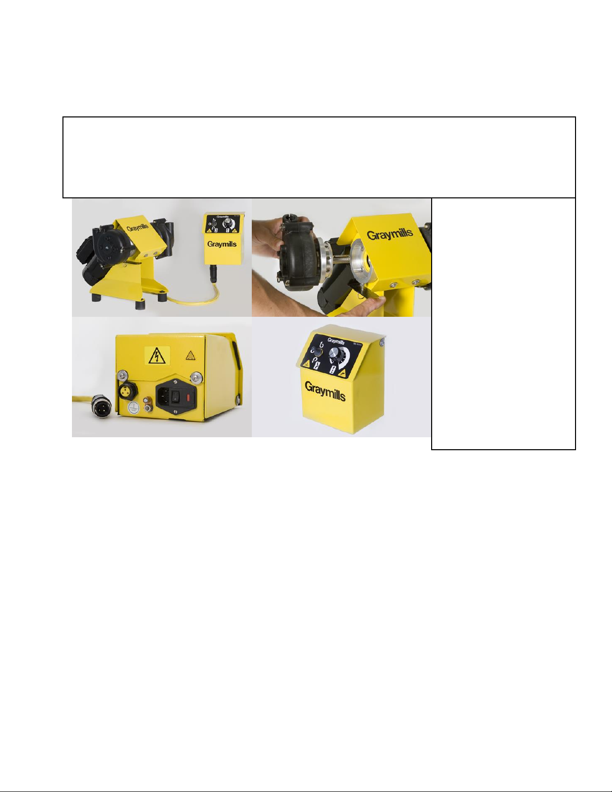
Figure A (Upper Left)
Dual Head Pump and
Remote Control Unit
Figure B (Upper Right)
Removable Head and
Release Lever
Figure C (Lower Left)
Remote Control UnitMotor Cord and Power
Cord connection
Figure D (Lower Right)
Remote Control UnitPump Speed and
Direction Control
Figure A
Figure B
Figure C
Figure D
for
Dual Head PERISTALTIC INK PUMPS
SAFETY-Do Not operate pump without both Pump Heads installed on the motor housing. Both Pump Heads
must be properly and securely installed on the pump for safe operation.
CAUTION-
Pump Heads must be fully inserted into motor’s hollow shaft and spring pin must be fully engaged into
mated aluminum adapter.
DO NOT depress Release Lever while pump is in operation. Stop pump before pushing release lever.
DO NOT attempt to remove, rotate or make any adjustments to Pump Heads while pump is in
operation.
WARNING-
Disconnect power supply to the Remote Control unit before making any connections, adjustments or
performing service work
The Dual Head Pump has two head sizes: small (PQS) and large (PQL). The pump motor will accept
either pump head size, but the remote control unit is factory set for one specific model. Do not drive
small heads with a large control unit, or drive a large head with a small control unit.
DO NOT disconnect motor or power cord while pump is in operation.
DO NOT plug motor cord into any other device except the model specific Remote Control unit.
DO NOT use the Remote Control unit to power or drive any other device.
OPERATING VOLTAGES
PPL-DV-DH, PPS-DV-DH DC Motor 115/230VAC 50/60 Hz 1 Phase. Voltage selection is done
automatically. No settings or switches to change.

ABOUT Dual Head PERISTALTIC PUMPS
The Dual Head Peristaltic Ink pump can be used to supply and draw back ink/fluid to one print deck, supply
the same ink/fluid to two different decks, or supply different ink/fluids to two different decks.
The Dual Head Peristaltic pump includes a hollow shaft pump motor (with female adapters and cord), two
pump heads (large or small) with male adapters, remote control unit, mounting frame and power cord. The
remote control unit is connected to the pump motor with a motor cord. (Left in Figure C, page 1) The power
cord is plugged into the remote control unit (Right in Figure C, page 1) and supplies 110 or 240VAC power.
The remote control unit automatically senses the voltage and is ready to operate. Once the pump motor cord
is plugged into the underside of the remote control unit and pump heads are properly installed, the system is
ready to pump.
The Remote Control unit is not splash-resistant, and therefore cannot be mounted in areas where fluid spills
can damage or disable the unit. The unit is designed to be mounted on a vertical surface with the switch and
cord receptacle facing down.
The pump and motor unit is splash-resistant under normal usage. DO NOT immerse the pump in fluids.
Contact a Graymills representative about mounting options for the pump and accessories, including stands,
filters, mixers and pails.
The Dual Head pump is offered in two models: PPS and PPL. The pump motor will accept either pump
head size, but the remote control unit is factory set for one specific model. Do not drive PPS heads
with a PPL control unit, or drive a PPL head with a PPS control unit.
.
For complete information about roller and hose, see the OMI #795-09456.
OPERATING PUMP
Turning On
See Figure C, page 1, showing power switch location on Remote Control Unit base.
Changing Pump Direction
Specifics of switch operation for speed and direction control are in OMI #795-09456.
Like all peristaltic pumps, stopping the Dual Head will not allow lines above the pump to gravity drain
because the rollers in the peristaltic pump head keep the hose partially closed after the motor is
stopped. It may be necessary to remove or rearrange hoses, particularly if both lines are going to a
single deck, in order for the deck to drain.
Fusing for the PPL-DV-DH and PPS-DV-DH Model
For 115 and 230VAC pump operation, use two (2) fuses, Part #780-91518 (5 x20mm, 5.0 Amp,
250VAC, Type FST, Slow Blow)
PUMP HEAD Removal/Installation
Installing or Removing a complete Pump Head, Male Adapter and Hose assembly with another of same.
For both PPS and PPL Dual Head Peristaltics, the following:
Stop pump and disconnect power supply.
Press Release Lever and remove current Pump Head Assembly from motor.
Ensure one large key is in the short shaft keyway of the new Pump Head Assembly.
Align this key with keyway of hollow shaft in motor and press Pump Head assembly into motor.
If necessary rotate Pump Head slightly until key and keyway align.
Press Release Lever and continue pressing Pump Head assembly into motor to close the gap between
two mating Adapters.
Rotate and Lock Pump Heads as desired.
Remove pressure from Release Lever to allow spring pin to engage with Male Adapter. Rotate and pull on
Pump Head to ensure it is properly secured and will not pull off.
Pump Head Assembly is now ready for operation.
 Loading...