

Graymills DDP-375 User Manual
Graymills
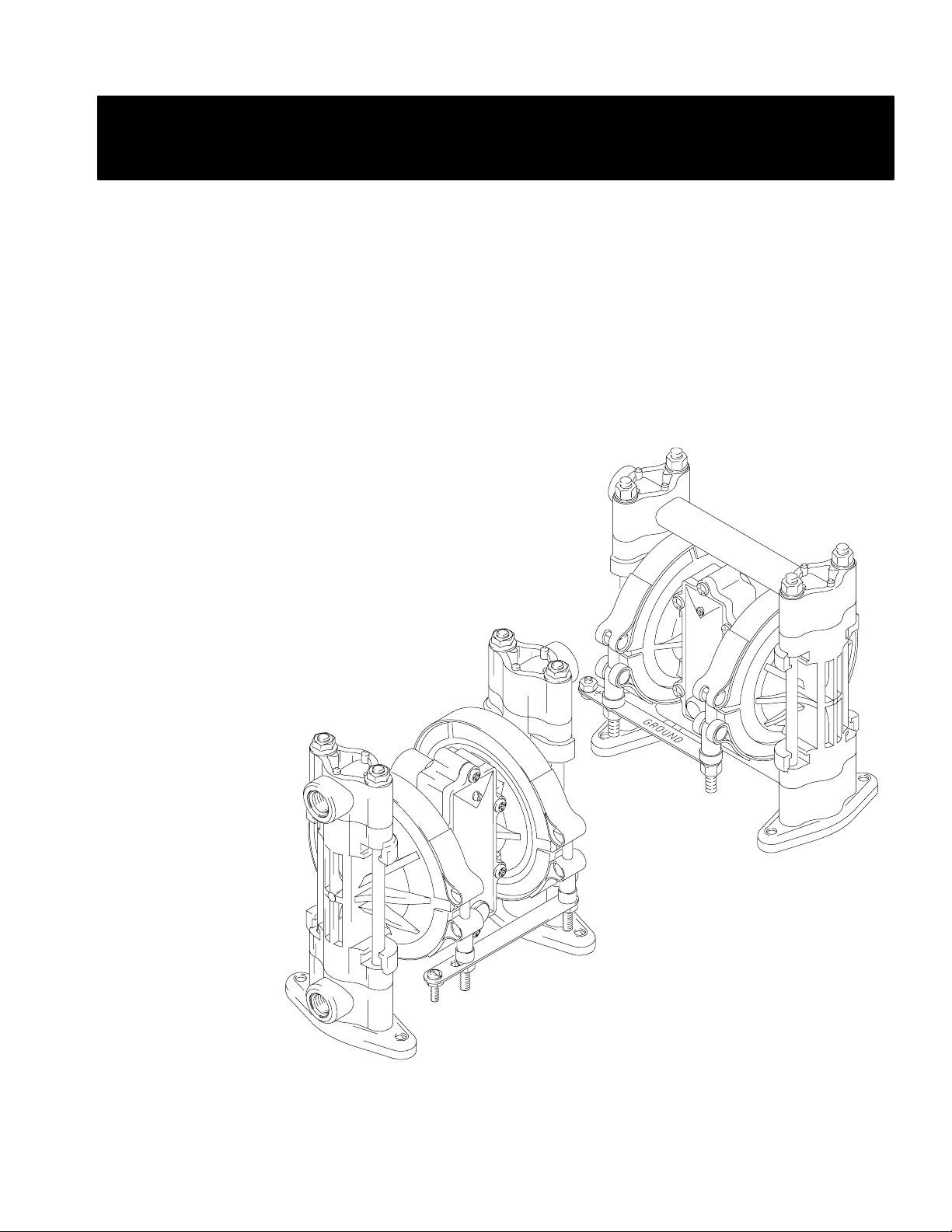
POLYPROPYLENE
Air Operated
Double Diaphragm Pumps
3/8" Model
Operations and Maintenance Instructions
100 psi (0.7 MPa, 7 bar) Maximum Fluid Working Pressure
100 psi (0.7 MPa, 7 bar) Maximum Air Input Pressure
795–90857
GM 6–02
Polypropylene Pumps, Series E
US and Foreign Patents Pending
WARNING/CAUTIONS
Read all these SAFETY INSTRUCTIONS
BEFORE installing or using this equipment. Keep this manual handy for reference/training.
Graymills Corporation 3705 N. Lincoln Avenue Chicago, Illinois 60613
773/248–6825 FAX 773/477–8673 www.graymills.com
Table of Contents
Safety Warnings 2. . . . . . . . . . . . . . . . . . . . . . . . . . . . . . . . .
Technical Data 4. . . . . . . . . . . . . . . . . . . . . . . . . . . . . . . . .
Installation 5. . . . . . . . . . . . . . . . . . . . . . . . . . . . . . . . . . . . .
Operation 11. . . . . . . . . . . . . . . . . . . . . . . . . . . . . . . . . . . . .
Troubleshooting 12. . . . . . . . . . . . . . . . . . . . . . . . . . . . . . . .
Maintenance 14. . . . . . . . . . . . . . . . . . . . . . . . . . . . . . . . . . .
Service
Replacing the Air Valve 16. . . . . . . . . . . . . . . . . . . . . . .
Repairing the Air Valve 18. . . . . . . . . . . . . . . . . . . . . . .
Ball Check Valves 21. . . . . . . . . . . . . . . . . . . . . . . . . . .
Diaphragm Repair 23. . . . . . . . . . . . . . . . . . . . . . . . . . .
Parts 26. . . . . . . . . . . . . . . . . . . . . . . . . . . . . . . . . . . . . . . . .
Performance Charts 29. . . . . . . . . . . . . . . . . . . . . . . . . . . . .
Dimensions 31. . . . . . . . . . . . . . . . . . . . . . . . . . . . . . . . . . .
Graymills Standard Warranty 32. . . . . . . . . . . . . . . . . . . . .
Graymills Information 32. . . . . . . . . . . . . . . . . . . . . . . . . . .
Symbols
Warning Symbol
WARNING
This symbol alerts you to the possibility of serious injury or
death if you do not follow the instructions.
Caution Symbol
CAUTION
This symbol alerts you to the possibility of damage to or
destruction of equipment if you do not follow the instructions.
Safety Alert Symbol
SAFETY ALERT
The safety Alert Symbol means ATTENTION! BECOME
ALERT! YOUR SAFETY IS INVOLVED!
WARNING
HAZARDOUS FLUIDS
Improper handling of hazardous fluids or inhaling toxic vapors can cause extremely serious injury or death
from splashing in the eyes, ingestion, or bodily contamination. Observe all the following precautions when
you handle hazardous or potentially hazardous fluids.
D Know what fluid you are pumping and its specific hazards. Take precautions to avoid a toxic fluid spill.
D Always wear appropriate clothing and equipment, such as eye protection and breathing apparatus, to
protect yourself.
D Store hazardous fluid in an appropriate, approved container. Dispose of it according to all Local, State,
and Federal guidelines for hazardous fluids.
D Secure the fluid outlet hose tightly into the receiving container to prevent it from coming loose and
improperly draining the fluid.
D Pipe and dispose of the exhaust air safely, away from people, animals, and food handling areas. If the
diaphragm fails, the fluid is exhausted along with the air. See Air Exhaust Ventilation on page 10.
D Use static wire hoses when pumping flammables.
D Keep containers closed when not in use.
2
WARNING
EQUIPMENT MISUSE HAZARD
Any misuse of the equipment or accessories, such as overpressurizing, modifying parts, using incompatible
chemicals and fluids, or using worn or damaged parts, can cause them to rupture and result in splashing in
the eyes or on the skin, other serious injury, or fire, explosion or property damage.
D This equipment is for professional use only. Observe all warnings. Read and understand all instruction
manuals, warning labels, and tags before you operate this equipment. If you are not sure, or if you have
questions about installation or operation, call Graymills Corporation.
D Never alter or modify any part of this equipment; doing so could cause it to malfunction.
D Check all equipment regularly and repair or replace worn or damaged parts immediately.
D Never exceed the recommended working pressure or the maximum air inlet pressure stated on your pump
or in the Technical Data on page 4.
D Do not exceed the maximum working pressure of the lowest rated component in your system. This
equipment has a 100 psi (0.7 MPa, 7 bar) maximum working pressure at 100 psi (0.7 MPa, 7 bar, )
maximum incoming air pressure.
D Be sure that all fluids and solvents used are chemically compatible with the wetted parts shown in the
Technical Data on page 4. Always read the manufacturer’s literature before you use fluid or solvent in
the pump.
D Never move or lift a pump under pressure. If dropped, the fluid section may rupture. Always follow the
Pressure Relief Procedure on page 11 before you move or lift the pump.
FIRE AND EXPLOSION HAZARD
Static electricity is created by the flow of fluid through the pump and hose. If the equipment is not properly
grounded, sparking may occur. Sparks can ignite fumes from solvents and the fluid being pumped, dust
particles, and other flammable substances, whether you are pumping indoors or outdoors, and can cause a
fire or explosion and serious injury and property damage.
D To reduce the risk of static sparking, ground the pump and all other equipment used or located in the
work area. Check your local electrical code for detailed grounding instructions for your area and type of
equipment. See Grounding on page 6.
D If you experience any static sparking or even a slight shock while using this equipment, stop pumping
immediately. Check the entire system for proper grounding. Do not use the system again until you have
identified and corrected the problem.
D Pipe and dispose of the exhaust air safely, away from all sources of ignition. If the diaphragm fails, the
fluid is exhausted along with the air. See Air Exhaust Ventilation on page 10.
D Do not smoke in the work area. Do not operate the equipment near a source of ignition or an open flame,
such as a pilot light.
3
SAFETY PRECAUTIONS
CAUTION
D Verify the chemical compatibility of the pump wetted parts and the substance being pumped, flushed or
recirculated. Chemical compatibility may change with temperature and concentration of the chemical(s)
within the substance being pumped, flushed or recirculated.
D The pump should not be used for the structural support of the piping system. Be certain system compo-
nents are properly supported to prevent stress on the pump parts.
D Do not allow pump to operate dry for long periods of time; this may cause unnecessary wear or damage
to the pump.
D Maximum temperature limits are based upon mechanical stress only. Certain chemicals will significantly
reduce maximum safe operating temperatures. Consult Graymills for chemical compatibility and temperature limits.
United States Government safety standards have been adopted under the Occupational Safety and Health Act. You should
consult these standards—particularly the General Standards, Part 1910, and the Construction Standards, Part 1926.
Technical Data For Pumps with Teflonr Diaphragms
Maximum fluid working pressure 100 psi (0.7 MPa, 7 bar). . . . . .
Air pressure operating range . . . 20 to 100 psi (0.14 to 0.7 MPa, .
1.4 to 7 bar ). . . . . . . . . . . . . . . . . . . . . . . . . . . . . . . . . . . . . . . . . .
Maximum air consumption 5.5 scfm (see chart). . . . . . . . . . . . . .
Maximum free flow delivery 6.5 gpm (24.6 lpm). . . . . . . . . . . . .
Maximum pump speed 330 cpm. . . . . . . . . . . . . . . . . . . . . . . . . .
Maximum suction lift 7 ft (2.1 m) dry, 12 ft (3.7 m) wet. . . . . . . .
Maximum size pumpable solids 1/16 in. (1.6 mm). . . . . . . . . . . .
Sound power level,
at full flow at 100 psi (0.7 MPa, 7 bar) 85 dBa. . . . . . . . . . . . .
Sound power level,
at 70 psi (0.48 MPa, 4.8 bar) and 1 gpm (3.8 lpm) 78 dBa. . .
Operating temperature range 40 to 150_ F (4.4 to 65.5_ C). . . . . . . .
Air inlet size . . . . . . . . . . . . . . . . . . . . . . . . . . . . . . 1/4 npt(f)
Fluid inlet and outlet size . . . . . . . . . . . . . . . . . . . 3/8” npt(f)
Wetted parts vary by models See pages 28 and 30. . . . . . .
Non-wetted external parts polyester (labels) glass–filled. .
polypropylene with conductive SST fibers
Weight (approximate) . . . . . . . . . . . . . 4.75 lb (2.2 kg). . . . .
Sound power level measured per ISO standard 9614–2.
VitonR, Teflon
DuPont Co.
Loctite
r is a registered trademark of the Loctite Corporation.
Santoprener is a registered trademark of the Monsanto Company.
Technical Data For Pumps with Hytrelr Diaphragms
Maximum fluid working pressure . . . . 100 psi (0.7 MPa, 7 bar)
Air pressure operating range . . . . 20 to 100 psi(0.14 to 0.7 MPa,
. . . . . . . . . . . . . . . . . . 1.4 to 7 bar). . . . . . . . . . . . . . . . . . . . . . .
Maximum air consumption . . . . . . . . . . . . 5.5 SCFM (see chart)
Maximum free flow delivery . . . . . . . . . . . . . 7 gpm (26.5 lpm)
Maximum pump speed . . . . . . . . . . . . . . . . . . . . . 330 cpm. . . .
Maximum suction lift 12 ft (3.7 m) dry; 21 ft (6.4 m) wet. . . . .
Maximum size pumpable solids . . . . . . . . . . . .1/16 in. (1.6 mm)
Sound power level,
at full flow at 100 psi (0.7 MPa, 7 bar) . . . . . . . . . . . . . 85
dBa
Sound power level,
at 70 psi (0.48 MPa, 4.8 bar) and 1 gpm (3.8 lpm) . . 78 dBa
Operating temperature range. 40 to 150_ F (4.4 to 65.5_ C)
Air inlet size . . . . . . . . . . . . . . . . . . . . . . . . . . . . . . 1/4 npt(f)
Fluid inlet and outlet size. . . . . . . . . . . . . . . . . . . . .3/8 npt(f)
Wetted Parts vary by model. . . . . . . . . See pages 27 and NO TAG.
Non-wetted external parts polyester (labels) glass–filled. .
polypropylene with conductive SST fibers
Weight (approximate) . . . . . . . . 4.75 lb (2.2 kg). . . . . . . . . . . . .
Sound power level measured per ISO standard 9614–2.
VitonR, Teflon
DuPont Co.
Loctiter is a registered trademark of the Loctite Corporation.
Santoprene
pany.
r, and Hytrelr are registered trademarks of the
r, and Hytrelr are registered trademarks of the
r is a registered trademark of the Monsanto Com-
4

Installation
General Information
D The Typical Installations in Fig. 5 to Fig. 7 are only
guides for selecting and installing system components.
Contact your Graymills distributor for assistance in
planning a system to suit your needs.
D Always use Genuine Graymills Parts and Accessories,
available from your Graymills distributor. If you supply
your own accessories, be sure they are adequately sized
and pressure rated for your system.
D Use a compatible, liquid thread sealant or Teflonr tape
on all male threads. Tighten all connections firmly to
avoid air or fluid leaks. Do not over-
tighten plastic threads.
D Reference numbers and letters in parentheses refer to
the callouts in the Figures and lists on pages 27 to 28.
CAUTION
Safe Operating Temperature
Minimum: 40_F (4.4_C); Maximum: 150_F (66_C).
Operating outside these temperature limits will
adversely affect the strength of the pump housing.
Certain chemicals may further reduce the operating
temperature range. Consult engineering guides for
chemical compatibilities and temperature limits, or
contact your Graymills distributor.
Tightening Threaded Fasteners Before
First Use
After unpacking the pump, and before using it for the first
time, check and retorque all external fasteners. See the
Service section for torque specifications. After the first
day of operation, retorque the fasteners again. Although
the recommended frequency for retorquing fasteners varies
with pump usage, a general guideline is to retorque fasteners every two months.
Mountings
WARNING
TOXIC FLUID HAZARD
Hazardous fluid or toxic fumes can cause
serious injury or death if splashed in the
eyes or on the skin, inhaled, or swallowed.
1. Read HAZARDOUS FLUIDS on page 2.
2. Use fluids and solvents which are compatible with
the equipment wetted parts. Refer to the Technical
Data section of all equipment manuals. Read the
fluid and solvent manufacturer’s warnings.
D Be sure the mounting can support the weight of the
pump, hoses, and accessories, as well as the stress
caused during operation.
D The pump can be used in a variety of installations, some
of which are shown in Fig. 5 to Fig. 7.
D For all other mountings, be sure the pump is adequately
secured.
Dual Manifolds
Dual manifold kits are available to enable you to pump two
fluids simultaneously, or to mix two fluids in the pump.
5
Installation
Grounding
WARNING
FIRE AND EXPLOSION HAZARD
This pump must be grounded. Before operating the pump, ground the system as
explained at right. Also read the section
FIRE AND EXPLOSION HAZARD on
page 3.
The polypropylene pump is not conductive.
When pumping conductive flammable fluids, always
ground the entire fluid system by making sure the fluid
system has an electrical path to a true earth ground (see
Fig. 5 through Fig. 7). Never use a polypropylene pump
with non-conductive flammable fluids as specified by
your local fire protection code.
US Code (NFPA 77 Static Electricity) recommends a
conductivity greater than 50 x 10
(mhos/meter) over your operating temperature range to
reduce the hazard of fire. Consult your fluid supplier to
determine the conductivity or resistivity of your fluid.
The resistivity must be less than 2 x 10¹² ohm-centimeters.
–12
Siemans/meter
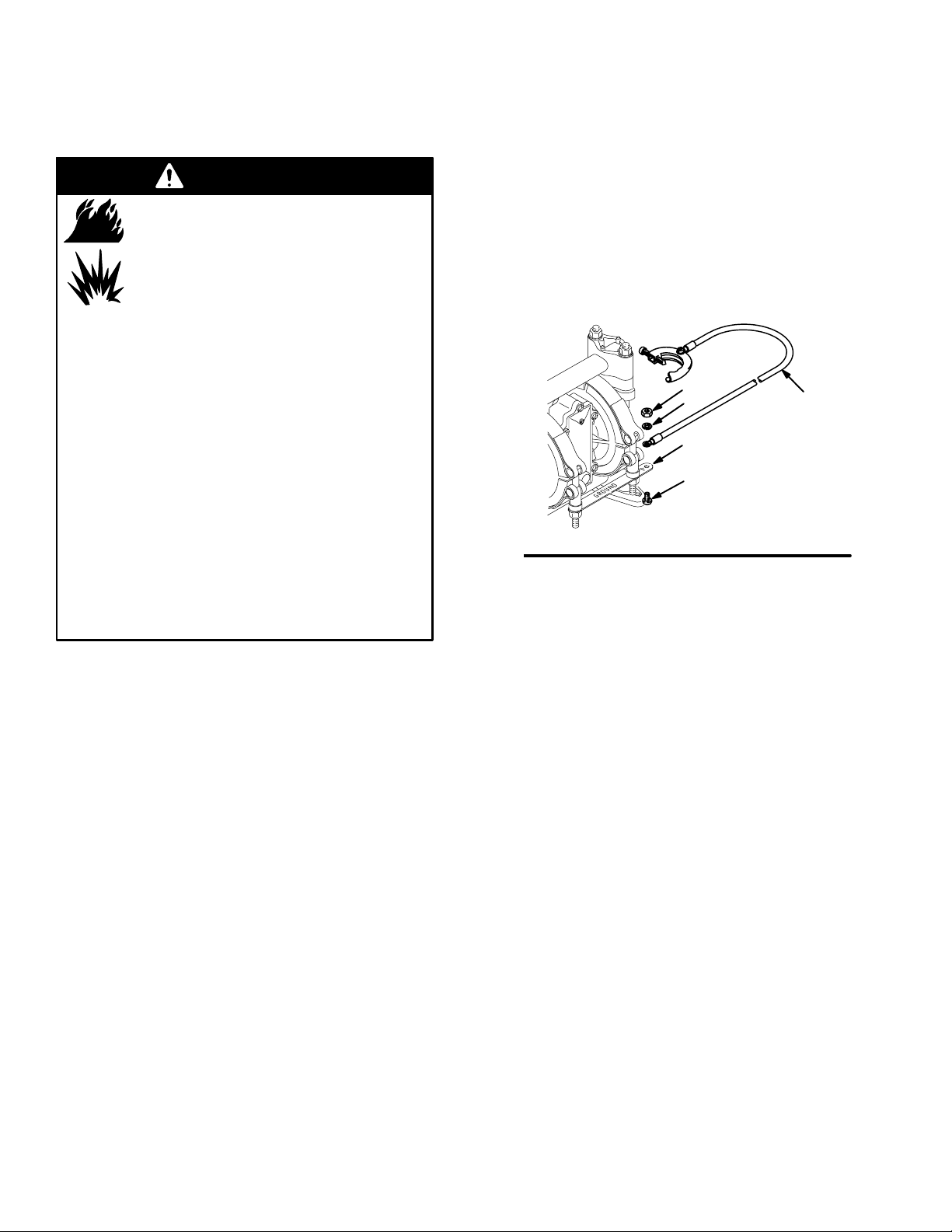
Ground all of this equipment:
D Pump: Attach a ground wire (Y) to the grounding strip
(112) with the screw (28), lockwasher (29) and nut (27),
as shown in Fig. 1. Connect the clamp end of the
ground wire to a true earth ground.
NOTE: When pumping conductive flammable fluids with
a polypropylene pump, always ground the fluid system. See
the WARNING at left. Fig. 5 through Fig. 7 show recom-
mended methods of grounding flammable fluid containers
during filling.
27
29
112
28
Fig. 1
D Air and fluid hoses: Use only electrically conductive
hoses.
Y
01432B
To reduce the risk of static sparking, ground the pump and
all other equipment used or located in the pumping area.
Check your local electrical code for detailed grounding
instructions for your area and type of equipment.
D Air compressor: Follow the manufacturer’s recommen-
dations.
D Solvent pails used when flushing: Follow your local
code. Use only metal pails, which are conductive. Do
not place the pail on a non-conductive surface, such as
paper or cardboard, which interrupts the grounding
continuity.
D Fluid supply container: Follow your local code.
6
Installation
Air Line
WARNING
A bleed-type master air valve (B) is required in your
system to relieve air trapped between this valve and the
pump. See Fig. 5 to Fig. 7. Trapped air can cause the
pump to cycle unexpectedly, which could result in
serious injury, including splashing in the eyes or on the
skin, injury from moving parts, or contamination from
hazardous fluids.
CAUTION
The pump exhaust air may contain contaminants.
Ventilate to a remote area if the contaminants could
affect your fluid supply. See Air Exhaust Ventilation
on page 10.
1. Install the air line accessories as shown in Fig. 5 to Fig.
7. Mount these accessories on the wall or on a bracket.
Be sure the air line supplying the accessories is grounded.
a. The fluid pressure can be controlled in either of
two ways. To control it on the air side, install an
air regulator (H). To control it on the fluid side,
install a fluid regulator (M) near the pump fluid
outlet (see Fig. 5).
Fluid Suction Line
D The pump fluid inlet is 3/8 npt(f). See Fig. 2. Screw the
fluid fitting into the pump inlet snugly. Use a compatible liquid thread sealant or TeflonR tape on connections to prevent air from getting into material line.
D At inlet fluid pressures greater than 15 psi (0.1 MPa,1
bar), diaphragm life will be shortened.
D See the Technical Data on page 4 for maximum suction
lift and flow rate loss at various lift distances.
Fluid Outlet Line
WARNING
A fluid drain valve (J) is required in your system to
relieve pressure in the hose if it is plugged. See Fig. 5
to Fig. 7. The drain valve reduces the risk of serious
injury, including splashing in the eyes or on the skin, or
contamination from hazardous fluids when relieving
pressure. Install the valve close to the pump fluid
outlet.
b. Locate one bleed-type master air valve (B) close
to the pump and use it to relieve trapped air. See
the WARNING above. Locate the other master air
valve (E) upstream from all air line accessories
and use it to isolate them during cleaning and
repair.
c. The air line filter (F) removes harmful dirt and
moisture from the compressed air supply.
2. Install an electrically conductive, flexible air hose (C)
between the accessories and the 1/4 npt(f) pump air
inlet (see Fig. 2). Use a minimum 1/4” (6.3 mm) ID air
hose. Screw an air line quick disconnect coupler (D)
onto the end of the air hose (C), and screw the mating
fitting into the pump air inlet snugly. Do not connect
the coupler (D) to the fitting yet.
D Use electrically conductive fluid hoses (N). The pump
fluid outlet is 3/8 npt(f). See Fig. 2. Screw the fluid
fitting into the pump outlet snugly.
D Install a fluid regulator (M) at the pump fluid outlet to
control fluid pressure, if desired (see Fig. 6). See Air
Line, step 1a, for another method of controlling pressure.
D Install a fluid drain valve (J) near the fluid outlet. See
the WARNING above.
7
Installation
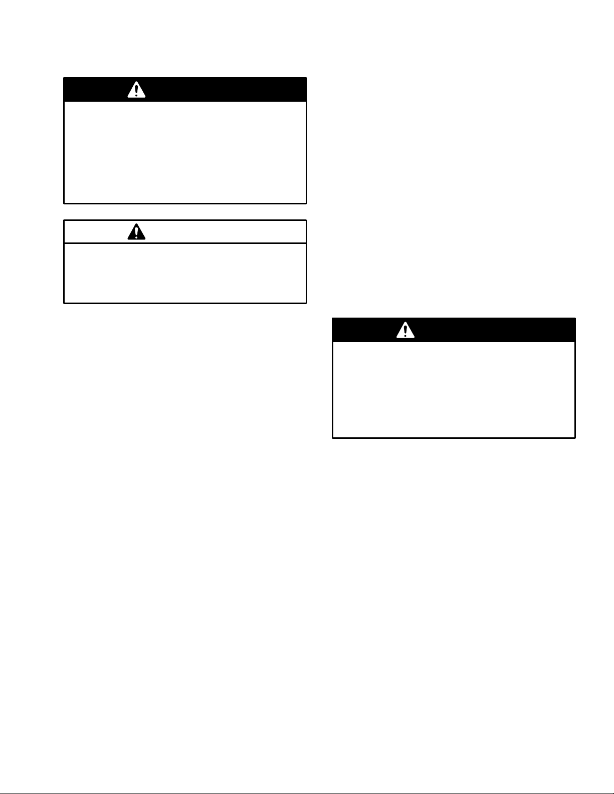
Changing the Orientation of the Fluid Inlet
and Outlet Ports
The pump is shipped with the fluid inlet and outlet ports
facing the same direction. See Fig. 2. If desired, the direction of one or both ports can be changed. Remove the
manifold(s) from the pump as explained in steps 1, 2, and 4
on page 21. Reattach with the port facing the desired
direction. Do not over-torque.
Apply thread lube, and torque to 50 to 60 in-lb (5.6
1
to 6.8 N-m). Do not over-torque.
2
1/4 npt(f) air inlet
3
3/8 npt(f) fluid inlet
4
3/8 npt(f) fluid outlet
5
3/8 npt(f) air exhaust port
2
1
4
Fluid Pressure Relief Valve
CAUTION
Some systems may require installation of a pressure
relief valve at the pump outlet to prevent overpressurization and rupture of the pump or hose. See Fig. 4.
Thermal expansion of fluid in the outlet line can cause
overpressurization. This can occur when using long
fluid lines exposed to sunlight or ambient heat, or when
pumping from a cool to a warm area (for example,
from an underground tank).
Overpressurization can also occur if the Husky pump is
being used to feed fluid to a piston pump, and the
intake valve of the piston pump does not close, causing
fluid to back up in the outlet line.
5
Fig. 2
Pump Shown
Apply thread lube, and torque to 50 to 60 in-lb (5.6
1
to 6.8 N-m). Do not over-torque.
2
1/4 npt(f) air inlet
3
3/8 npt(f) fluid inlet
2
4
3/8 npt(f) fluid outlet
5
3/8 npt(f) air exhaust port
1
01459B
KEY
3
A 3/8 npt(f) fluid inlet port
B 3/8 npt(f) fluid outlet port
C Pressure relief valve
Part No. 110134 (aluminum)
Part No. 112119 (stainless steel)
1
Install valve between fluid inlet and outlet ports.
2
Connect fluid inlet line here. Use a compatible
liquid thread sealant or TeflonR tape on connection to prevent air from getting into the
material line.
3
Connect fluid outlet line here.
B 1
3
4
1
C
Fig. 3
8
3
Fig. 4
5
01459B
A
2
01539B
Installation
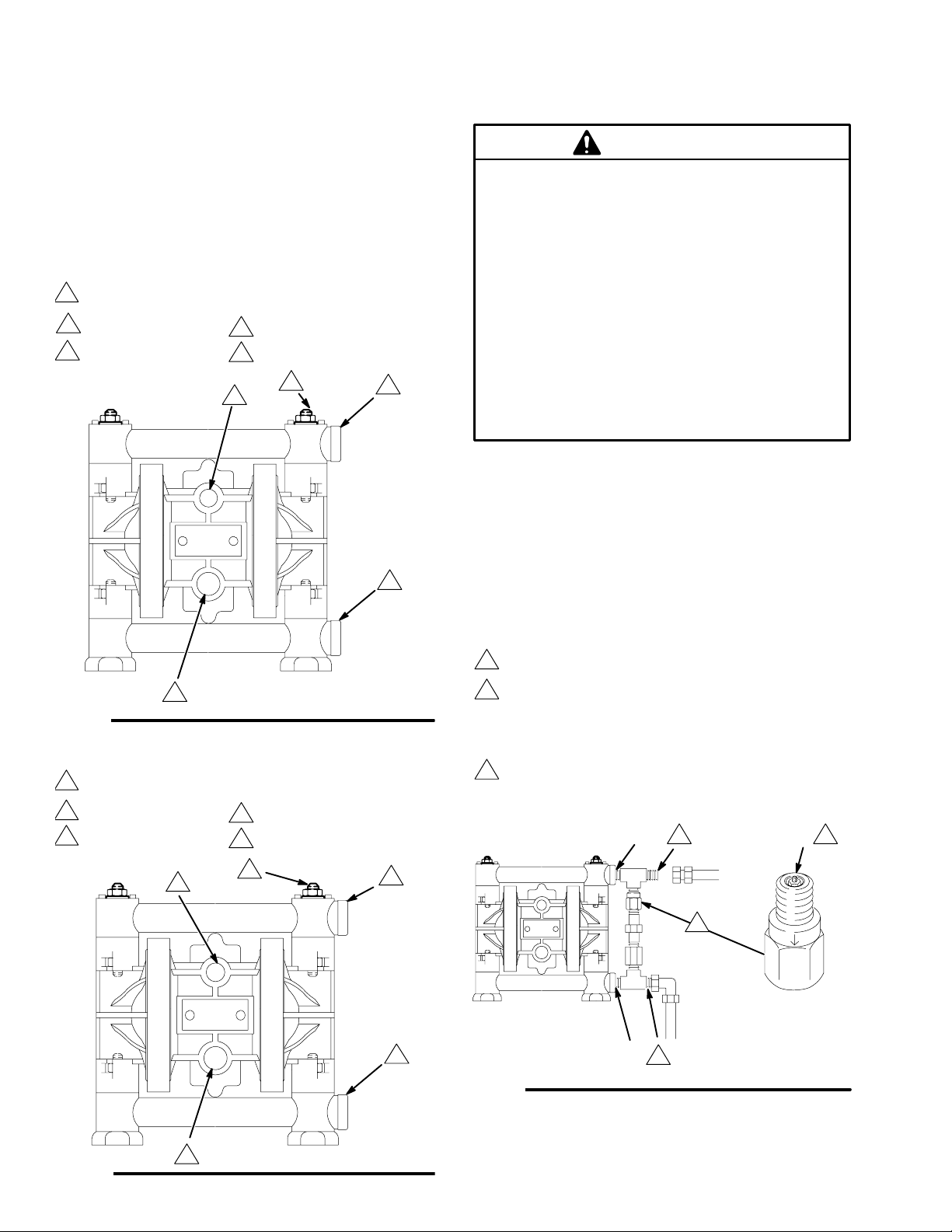
BUNG-MOUNT TRANSFER INSTALLATION
KEY
A 3/8” Diaphragm Pump
B Bleed-Type Master Air
Valve
(required for pump)
C Air Supply Line
D Air Line Quick Discon-
nect
E Master Air Valve (for
accessories)
F Air Line Filter
E
F
H Pump Air Regulator
J Fluid Drain Valve (required)
L Fluid Suction Line
M Fluid Inlet Filter
N Fluid Supply Hose
Y Ground Wire (required; see
page 6
for installation instructions)
H
B
C
N
D
A
M
WALL-MOUNT TRANSFER INSTALLATION
KEY
A 3/8” Diaphragm Pump
B Bleed-Type Master Air
Valve
(required for pump)
C Air Supply Line
D Air Line Quick Discon-
nect
E Master Air Valve (for
accessories)
F Air Line Filter
E
H Pump Air Regulator
J Fluid Drain Valve
(required)
L Fluid Suction Line
N Fluid Supply Hose
S Wall Bracket
T Bung Adapter
Y Ground Wire (required;
see page 6
for installation instructions)
H
F
B
C
D
A
J
L
T
Y
N
J
L
Y
Fig. 5
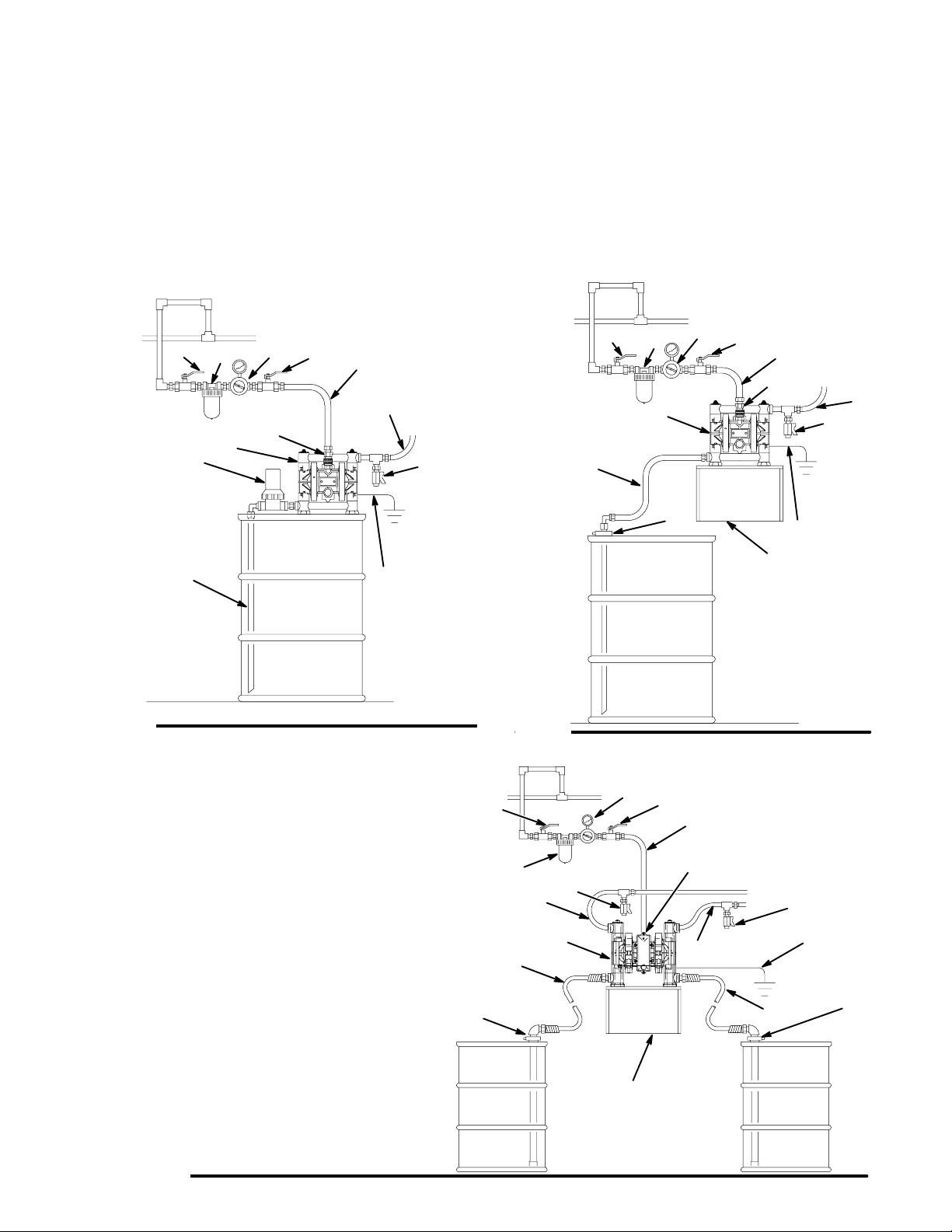
WALL-MOUNT SPLIT MANIFOLD TRANSFER
INSTALLATION
KEY
A 3/8” Diaphragm Pump
B Bleed-Type Master Air Valve
(required for pump)
C Air Supply Line
D Air Line Quick Disconnect
E Master Air Valve (for accessories)
F Air Line Filter
H Pump Air Regulator
J Fluid Drain Valve (required)
L Fluid Suction Line
N Fluid Supply Hose
S Wall Bracket
T Bung Adapter
Y Ground Wire (required; see page 6
for installation instructions)
01444B
S
Fig. 6
01457B
H
E
B
C
F
J
N
A
L
T
D
J
Y
N
T
L
Fig. 7
S
TI2196A
9
Installation
Air Exhaust Ventilation
WARNING
FIRE AND EXPLOSION HAZARD
Be sure to read FIRE OR EXPLOSION
HAZARD and TOXIC FLUID HAZARD
on page 2, before operating this pump.
Be sure the system is properly ventilated for
your type of installation. You must vent the
exhaust to a safe place, away from people,
animals, food handling areas, and all
sources of ignition when pumping flammable or hazardous fluids.
Diaphragm failure will cause the fluid being pumped to
exhaust with the air. Place an appropriate container at
the end of the air exhaust line to catch the fluid. See
Fig. 8.
The air exhaust port is 3/8 npt(f). Do not restrict the air
exhaust port. Excessive exhaust restriction can cause erratic
pump operation.
To exhaust to a remote location:
1. Remove the muffler (11) from the pump air exhaust
port.
WARNING
PRESSURIZED EQUIPMENT HAZARD
To reduce the risk of serious eye injury from
ice particles, never operate the pump with
the air exhaust port open. Ice may form
during pump operation, and ice particles will be ejected
from the port along with the exhaust air. If the muffler
(11) is removed, always connect an air exhaust hose to
the exhaust port.
2. Install an electrically conductive air exhaust hose (X)
and connect the muffler to the other end of the hose.
The minimum size for the air exhaust hose is 3/8 in.
(10 mm) ID. If a hose longer than 15 ft (4.57 m) is
required, use a larger diameter hose. Avoid sharp bends
or kinks in the hose.
3. Place a container (Z) at the end of the air exhaust line
to catch fluid in case a diaphragm ruptures. If the fluid
is flammable, ground the container. See Fig. 8.
Fig. 8
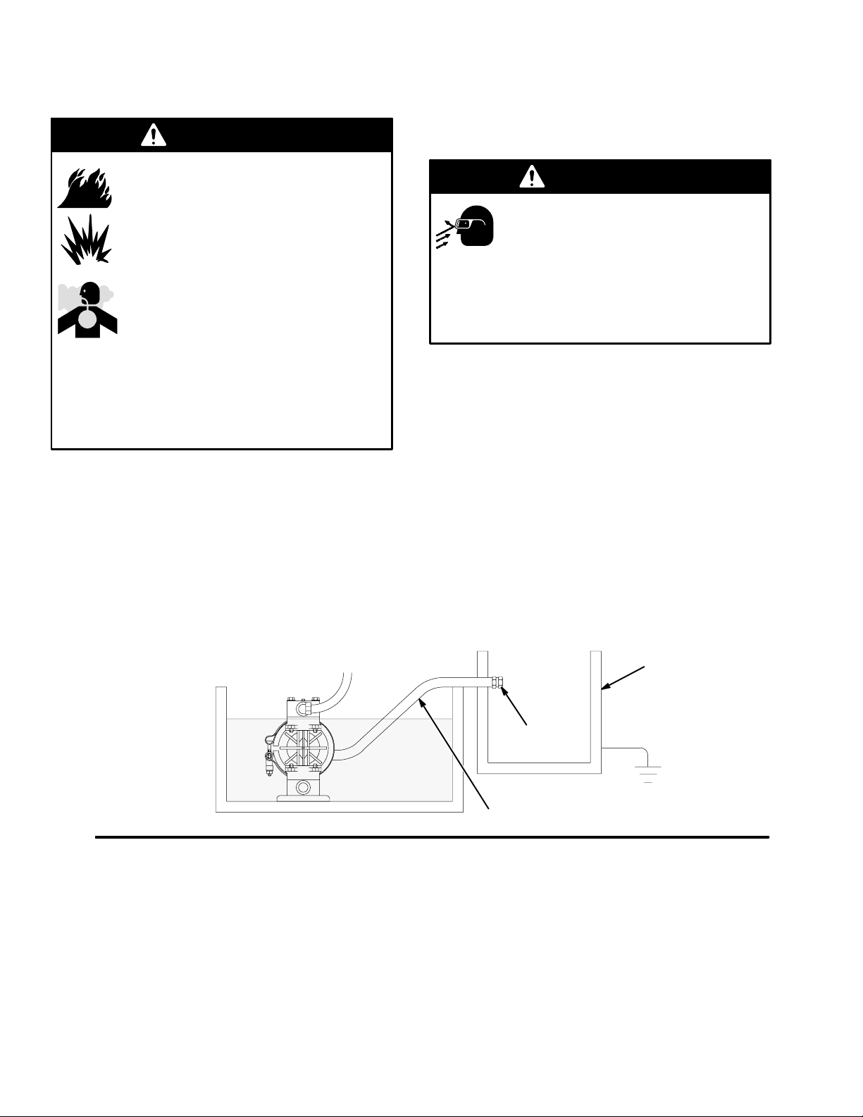
VENTING EXHAUST AIR (Submerged Installation Shown)
See Fig. 4 for accessories
In a submerged installation (as shown), all wetted and non-wetted pump
parts must be compatible with the fluid being pumped.
11
X
Z
01445A
10
 Loading...