

Graymills Bed Filter User Manual
Heavy Duty Coolant Tank /
Bed Filter / Magnetic Separator
Operation and
Maintenance
Instructions
WARNINGS/CAUTIONS
Do not install or operate until you have read all
warnings and instructions and understand the
operation.
• Turn off power to the unit before beginning maintenance on the Graymills Coolant Tank, Bed Filter, or
Magnetic Separator.
• Read and follow all safety instructions supplied with
chemical/coolant being used in your machine tool.
• To avoid damage to the unit, check power source for
proper voltage and phase. Unit comes standard with a
transformer capable of accepting either 230V or 460V,
3 phase power.
• As in all electrical circuits, it is highly recommended
that an electric safety device such as a fusible disconnect or circuit breaker be installed in line before unit is
connected.
• Do not use an extension cord to supply bed filter system.
795-90248
GM 4-00
BFCT40 Bed Filter with 35-gallon pump/tank
combination
MS40 Magnetic Separator for BFCT40
BFCT80 Bed Filter with 90-gallon pump/tank
combination
MS80 Magnetic Separator for BFCT80
• Make sure that pump is spinning freely. See
Maintenance instructions.
• Check the rotation of the pump before starting operation. Rotation should be in a clockwise direction looking down on the motor (match arrow on pump body).
• Ensure that all fittings and connections are properly
tightened.
• It is important that sensitive electronic equipment,
such as:
• personal electronic devices such as pacemakers
• computers
• magnetic media such as credit cards
be kept a safe distance from the Magnetic Separator
when it is in operation.
Never work with equipment you feel may be
unsafe. Contact your Supervisor immediately.
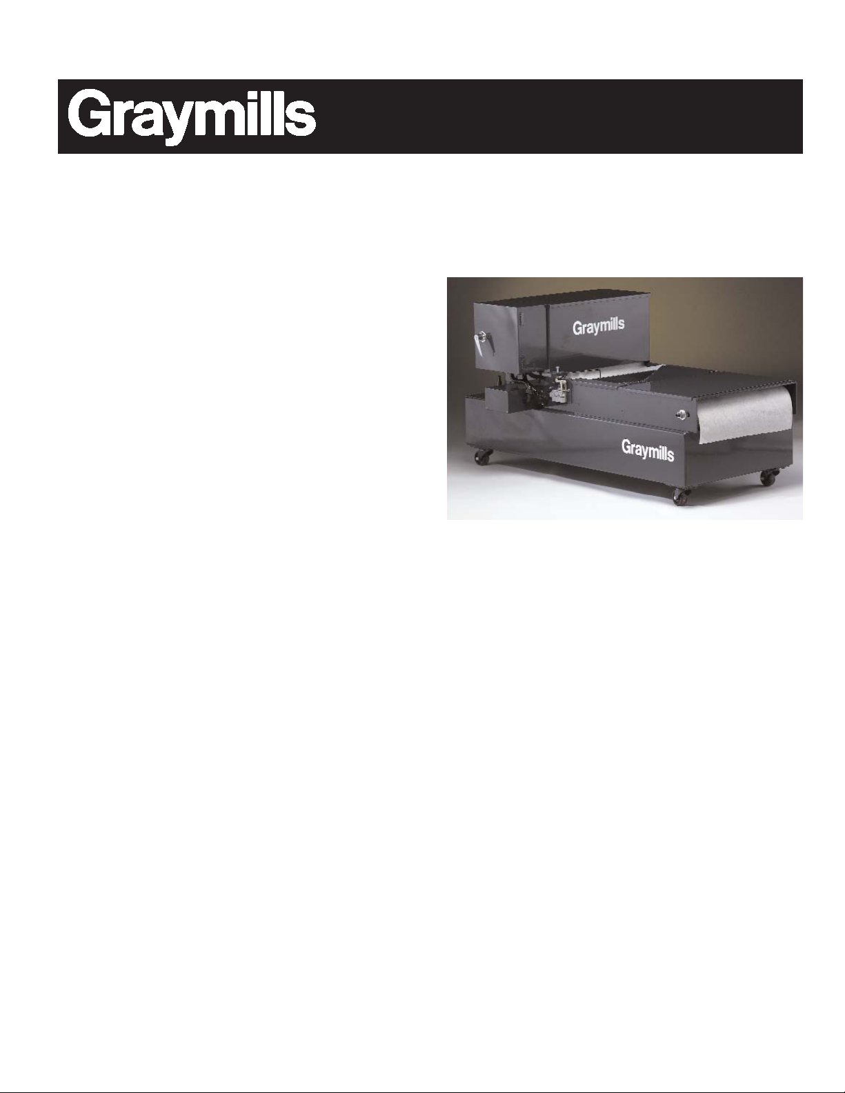
SYSTEM FEATURES
The Graymills combined Coolant Tank, Bed Filter and
(optional) Magnetic Separator are designed to keep your
cutting, grinding, drilling and milling machinery operating at peak performance. By filtering out harmful contaminants, coolant life is greatly extended, saving both
replacement and labor costs.
Coolant flows into the diffuser tray, which separates larger chips and milling by-products. The liquid then pours
onto the filter bed where it is sieved by the filter media.
As the contaminants accumulate and clog the filter
media, the solution rises in the filter bed until the float
switch is triggered. This starts the motor that moves the
chain conveyor/filter media along, until it is replaced with
clean material. The soiled filter media is moved to a
sludge box.
The benefits are:
• Keeps the coolant clean. Reduces frequency of coolant
replacement. Reduces operating costs.
• Keeps the workpiece surface cleaner.
• Grinding wheel does not need to be dressed as often.
Increases productivity and grinding wheel life.
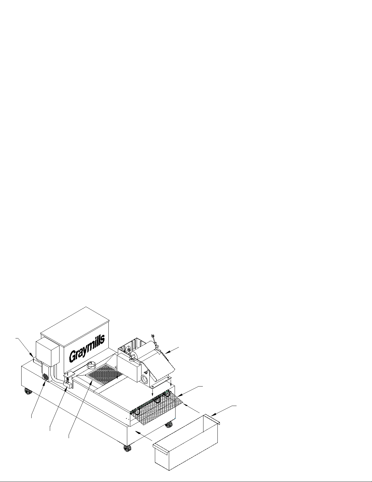
SYSTEM COMPONENTS
A Pump
Used to deliver the coolant in the tank to the machine.
B Gear reducing motor
Moves the filter media along as necessary.
C Liquid Level Control
Float switch mechanism controls the level of coolant
collected in the filter valley. Switch operates the motor
that moves the filter media along.
D Diffuser Tray
Collects larger particles before the coolant is deposited
on the filter media. Also helps spread deposits evenly,
increasing media life.
E Filter Media
Collects the particles to filter the coolant. Standard roll is
rated at 20 micron. Other micron ratings available; contact Graymills for details. 150 yard rolls.
F Sludge Box
Used to accumulate spent filter media and prevent run off
to floor.
G (Optional) Magnetic Separator
Removes ferrous material from coolant before straining
for other debris. Can be installed directly on bed filter for
dual stage separation, or run independently with pumping
system.
SET UP AND INSTALLATION
Coolant Tank and Bed Filter
1.Unpack and inspect unit carefully to verify that everything is intact and there are no obstructions in the chain
mechanism or any other electrical or mechanical components. Do not run power to system at this time.
2.Position the unit in the area in which it will be operating.
3.Remove diffuser tray and lids from paper compartment
and chain area.
4.Fill the tank cavity with coolant until level is approximately 1 to 2 inches below side wall of tank, being
careful not to overfill.
5. Proceed to feed paper through the opening at the bottom of the paper compartment and onto the chain until
the chain is completely covered. Extend filter media a
few inches past the chain. Position the sludge collection
box at the end of the tank and place end of filter paper
over box so soiled media drops into box.
6. Replace lids and reinstall diffuser tray.
7. Pump and bed filter may be wired separately in the event there is a power feed
from your machine tool to incorporate
the pump operation into the main
control. If not, you may run a
water-tight conduit (customer supplied) from the pump to the main
control box and bring your main
power feed into it for a central connection. All electrical work must be
according to applicable codes.
8. Make the necessary connections
A
B
C
D
G
E
F
Figure 1
 Loading...