

Graymills 795-90716 LKN User Manual

795-90716
06/08
Graymills
LKN-Series LIFTKLEEN® Parts Washer
Aqueous and Solvent Models
Operations and Maintenance Instructions
Be sure anyone operating this unit reads and understands all warnings and instructions. Keep this
manual available for reference/training.
TABLE OF CONTENTS
INTRODUCTION.....................................................................................................................................................................2
CONSTRUCTION FEATURES...............................................................................................................................................2
TANK ASSEMBLY..............................................................................................................................................................2
PLATFORM ASSEMBLY....................................................................................................................................................2
AUTOMATIC LID ASSEMBLY............................................................................................................................................2
PNEUMATIC CONTROL....................................................................................................................................................2
TOUCH-SCREEN PLC CONTROL....................................................................................................................................3
SAFETY WARNINGS .............................................................................................................................................................3
GENERAL WARNINGS – READ BEFORE OPERATING..................................................................................................3
POWER SUPPLY, WIRING AND GROUNDING ...............................................................................................................5
MACHINE INSTALLATION.....................................................................................................................................................5
MACHINE STARTUP..............................................................................................................................................................6
THE LKN CONTROL ..............................................................................................................................................................7
OPERATOR INTERFACE..................................................................................................................................................7
LKN CONTROL SCREEN MAP .........................................................................................................................................7
HOME SCREEN.................................................................................................................................................................8
CYCLE SETUP...................................................................................................................................................................9
SETTING CYCLE PARAMETERS.................................................................................................................................9
SETTING A TIMED CYCLE...........................................................................................................................................9
24 HOUR HEATER TIMERS............................................................................................................................................10
SETTING MACHINE CLOCK.......................................................................................................................................10
INDIVIDUAL DAY SETTINGS......................................................................................................................................10
ENABLE/DISABLE.......................................................................................................................................................10
SETTING ON/OFF TIME..............................................................................................................................................10
MANUAL OPERATIONS..................................................................................................................................................11
THE AUTOMATIC CYCLE....................................................................................................................................................12
CONDITIONS TO BEGIN AUTOMATIC CYCLE:........................................................................................................12
INITIATING AUTOMATIC CYCLE: ..............................................................................................................................12
ENDING AUTOMATIC CYCLE:...................................................................................................................................12
OPTIONAL ITEMS................................................................................................................................................................12
FILTRATION SYSTEMS ..............................................................................................................................................12
SUPERFLO PUMP.......................................................................................................................................................12
TEMPERATURE CONTROL SETTING.......................................................................................................................12
LKN DIMENSIONS AND SPECIFICATIONS*......................................................................................................................13
LOCK-OUT PROCEDURES ........................................................................................................................................13
LUBRICATION .............................................................................................................................................................13
PNEUMATIC SYSTEM.................................................................................................................................................13
TROUBLESHOOTING GUIDE..............................................................................................................................................14
WARRANTY..........................................................................................................................................................................15
Graymills Corporation – 3705 N. Lincoln Avenue – Chicago, IL 60613 – 773-248-6825 – Fax 773-477-8673 – www.graymills.com
– 1

795-90716
06/08
INTRODUCTION
The Graymills LKN Liftkleen is a heavy-duty, multi-function, commercial-type parts cleaner designed for both industrial and automotive
applications. It is available for use with either heated aqueous or unheated solvent cleaning solutions.
Standard LKN features include, but are not limited to:
• PLC control
• Automated pneumatic lift platform with oscillation feature
• Automated pneumatic lid operation
• Timed or untimed cycles
• 24/7 timer capability to turn on and off optional heaters to coincide with production demands
A number of optional features are available:
• Superflo® Agitation Pumping Unit with an output of up to 10,000 gallons per hour
• Filtration system
• Turbo-Boost filtration system – Agitation and Filtration all in one package!
• Roller conveyor platform (instead of standard grate)
• Loading and unloading conveyors
• Drop-in type immersion heaters
• Skimmer for removing oil and grease-type contaminants
CONSTRUCTION FEATURES
TANK ASSEMBLY
The Liftkleen was designed to withstand the rugged demands of heavy-duty industrial and automotive parts cleaning. All tanks are
leak-tested for 24 hours after welding. The bottom of the tank utilizes double wall construction and is supported by four channels.
Openings are provided to facilitate moving the Liftkleen with a fork-lift truck. A drain is located in the bottom or rear of the tank to which
permanent drain connections can be attached. On all models, the tank sides and cover are insulated with 1” thick polystyrene foam
(equal to two-plus inches of fiberglass).
PLATFORM ASSEMBLY
The Platform is designed to handle loads specified for the particular model of Liftkleen. The platform consists of a welded steel frame
which supports an open composite grate. The platform assembly is made up of a steel weldment, platform support weldment, support
rollers with bearings, hardened steel roller axles, and one or two pneumatic cylinders (depending on the model). Rollers and bearings
on all Liftkleen units are located outside the tank and are never immersed in the cleaning solution. This helps keep moving parts
lubricated. The standard open composite grate of the platform assembly can be rep laced with either a stainless steel grate or roller
conveyor platform, both optional.
AUTOMATIC LID ASSEMBLY
On all LKN models, opening and closing the lid is accomplished automatically via pneumatic cylinder(s). Lids, as well as tanks, are
insulated on all units. The internal face of the lid is made of stainless steel to eliminate corrosion caused by vapor condensation.
Unheated units contain a temperature sensitive automatic lid-closing feat ure. In the event of a fire in the tank, the platform assembly
lowers and the lid closes automatically.
PNEUMATIC CONTROL
The LKN is furnished with a pneumatic system that raises and lowers the platform, a master on/off valve and a filter/regulator/
lubricator. The agitating lift platform contains air controls that agitate the platform up and down through a range of five inches with a
variable frequency of strokes per minute. Stroke frequency depends on load and available air pressure and volume. When available,
adjustments to the system should be made under operating load conditions.
All pneumatic tubing connections are made with Instant Fittings. These make it possible to connect and disconnect the tubing to the
fittings without the use of a wrench. To disconnect a tube, simply push in the collet and pull the tube from the socket. To engage the
tube, push it into the fitting until it hits the stop. Sealing of the connection is achieved with an O-Ring in the fitting.
The air cylinder for raising, lowering and oscillating (agitating) the work platform has pneumatic lin es connected to both its “up” and
“down” ports. This provides for smooth, positive, controlled motion in both travel directions with minimal dependenc e on the weight of
the work load.
The “down” portion of the air cylinder is controlled by flow control valves and/or speed control mufflers. The speed will vary with the
weight of the work load. However, the speed control muffler can be adjusted “in” to slow the downward movement and “out” to speed it
up. The advantage of this method is a reduction of air consumption.
Graymills Corporation – 3705 N. Lincoln Avenue – Chicago, IL 60613 – 773-248-6825 – Fax 773-477-8673 – www.graymills.com
– 2
795-90716
06/08
Pneumatic schematic included at rear of manual.
TOUCH-SCREEN PLC CONTROL
Touch-Screen PLC controls are standard on all LKN units. This control has been desi gned to provide the operator with an easy and
consistent method of control. From the main screen, all of the machine functions may be easily accessed and current cycle functions
are displayed.
The standard PLC control is field-upgradeable to add pumps, heat, skimmers and filtration units with a minimum of cost to the customer
while providing maximum benefit.
Control circuit schematic included at rear of manual.
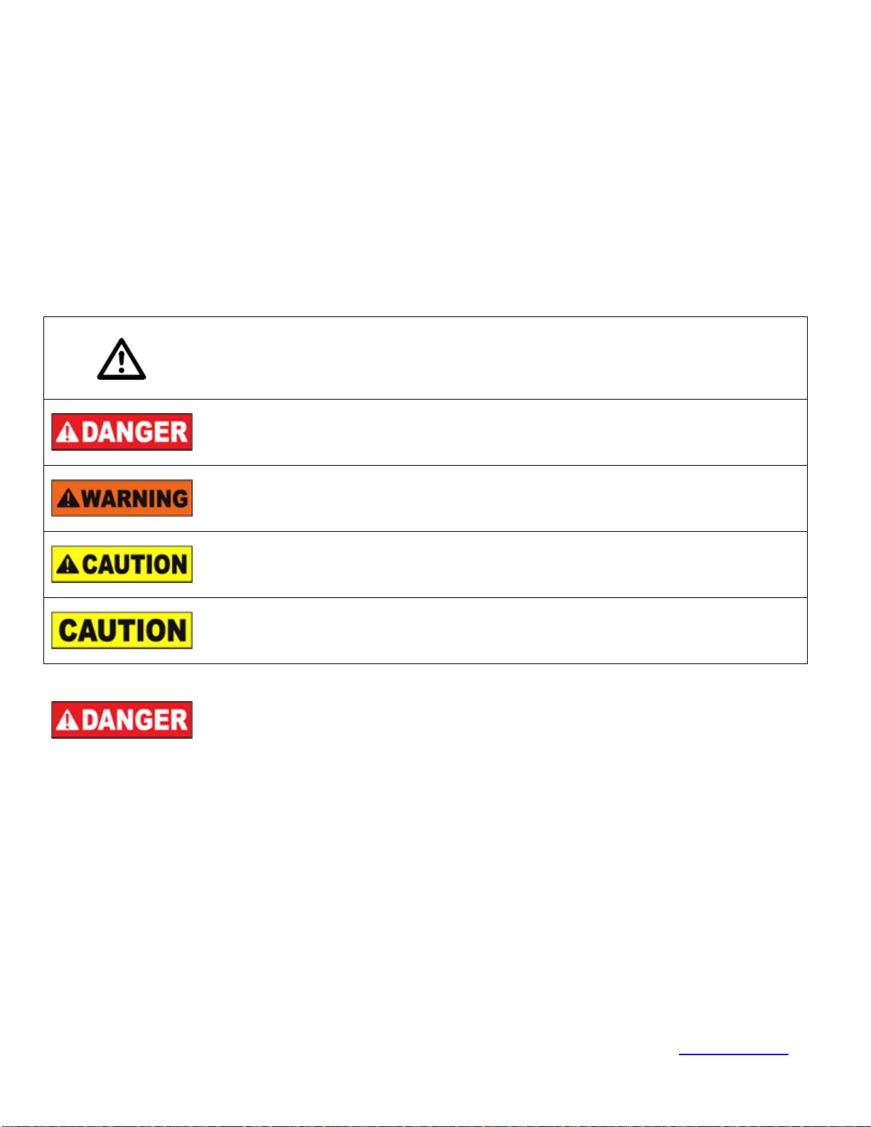
SAFETY WARNINGS
You will find safety information on the following pages and on equi pment. The following Safety Statements explain their meaning:
This is the safety alert symbol. It is used to alert you to potential personal injury
hazards. Obey all safety messages that follow this symbol to avoid personal injury or
GENERAL WARNINGS – READ BEFORE OPERATING
death.
DANGER indicates a hazardous situation which, if not avoided, will result in death or
serious injury.
WARNING indicates a hazardous situation which, if not avoided, could result in death
or serious injury.
CAUTION, used with the safety alert symbol, indicates a hazardous situation which, if
not avoided, could result in minor or moderate injury.
CAUTION, without the safety alert symbol, is used to address practices not related to
personal injury.
All Models Heated Models
• Do NOT use as a cleaning fluid or contaminate
cleaning fluid with any flammable materials such as
gasoline, mineral spirits or alcohol (under 100°F
flashpoint).
• Drain parts to be cleaned of any flammable material or
combustible material before placing inside cleaning
tank. Even small quantities of such unauthorized
materials can cause a health and safety hazard which
might result in serious personal injury or death.
• Be sure to follow label instructions provided with any
fluid used in this unit. See MACHINE INSTALLATION
Section for recommended cleaning compounds.
Graymills Corporation – 3705 N. Lincoln Avenue – Chicago, IL 60613 – 773-248-6825 – Fax 773-477-8673 – www.graymills.com
• Never use a flammable or combustible fluid in this
unit. Use only nonflammable, non-combustible,
water-based, low foaming cleaning compounds in this
machine.
Unheated Models
• Do NOT install near open flames or heat.
• Do NOT smoke near parts cleaner.
• Use only combustible fluids with a flash point of 104°F
or higher.
– 3

795-90716
06/08
All Models
• Never work with equipment you feel may be unsafe.
Contact your supervisor immediately if you feel a
piece of equipment is in an unsafe condition.
• Cleaning solutions may be irritating to skin and eyes.
Always wear gloves, apron and safety glasses when
using. If splashed in eyes, flush thoroughly with
water and follow directions on cleaning solution
MSDS.
• Install machine in a well ventilated area to avoid
possible buildup of cleaning solution fumes.
• These units have moving parts, pinch-points and
close tolerances. Always stand clear of lift platform
and lid when operating as the lid could unexpectedly
open or the platform operate. Keep hands and fingers
away from tank when operating platform.
• DO NOT perform any maintenance work on Liftkleen
without having the air shut-off valve in the “Off”
position and main air lines to cylinders disconnected.
Disconnect electrical power. Follow lock out
procedures.
All Models
• When making an initial batch of cleaning solution or
when adding compound, follow manufacturer’s
directions exactly. Wear appropriate safety equipment
as recommended. Add only small amounts at one time
to prevent a sudden boiling and/or eruption of liquid
which will create a hazardous condition. NEVER dump
in a large quantity at one time.
• If any cleaning solutions are splashed on clothing,
change promptly and thoroughly wash any body areas
which have been in contact with solution. Apply
lotion. Do NOT permit saturated clothing to remain in
contact with skin. Consult solution manufacturer’s
MSDS for further instruction.
• When turning air on or off or when operating the lift
platform, stay clear of the lid, lift platform and
operating mechanism as the lid could unexpectedly
open or the platform operate.
Heated Models
• Maximum operating temperature is 180°F. Higher
temperatures will cause increased risk of personal
injury and damage to the unit. Remember, any
temperature above 115°F can cause severe burns.
• The operator and anyone working in or around the
Liftkleen must be cautious of the hot tank contents
(cleaning solution, platform, lid, parts, etc.) and of the
steam which escapes when the lid opens. Be sure
everyone who works in or around the Liftkleen reads
and understands how to use the chemicals or
compounds being used, as well as the machine.
Heated Models
• Pump intake is above heater coil. Turn heater (an
optional feature) and pump (an optional feature) off
immediately. Failure to keep heater coil immersed can
cause heater to burn out.
• Tanks should be cleaned out on a regular basis to
prevent sludge from building up around heaters.
Failure to do so could result in damage to the heaters.
Graymills is not responsible for such damage.
Unheated Models
• Unit is equipped with a fusible safety link mechanism.
In the event of a fire, the fusible link will melt at 165°F.
This will cause the control to lower the platform and
close the lid, reducing oxygen supply to the fire. The
unit will cease to function until the safety-link has
been replaced
All Models
• If you have purchased a unit with a carbon steel tank,
observe the following before using: Water-based
cleaning materials will generate water vapors.
Surfaces above the liquid level will be subject to
rusting (this condition exists with any manufacturer’s
unit). This is primarily surface rust and does not
appreciably affect the serviceability of the unit.
However, if your cleaning requirements cannot
tolerate any rust or contamination, please contact the
factory for information on stainless steel models
before putting the unit into service. Also, be sure your
Graymills Corporation – 3705 N. Lincoln Avenue – Chicago, IL 60613 – 773-248-6825 – Fax 773-477-8673 – www.graymills.com
cleaning material contains a rust inhibitor. (Check
with your cleaning fluid supplier.) The Graymills
Warranty does not cover rusting of carbon steel units
used with water-based material.
Heated Models
• Either turn heater off or use the 24/7 heater timer
when unit is to be idle for extended periods (overnight
or weekends). Over time, the cleaning solution could
evaporate enough to damage heater coil.
– 4

POWER SUPPLY, WIRING AND GROUNDING
795-90716
06/08
• Failure to permanently ground the unit and controls
before connecting to electrical power can cause
shock, burns or death. Install ground and wiring
according to local and national electrical code
requirements.
• Unit must be properly grounded to prevent electric
shock hazard. Should connections become cracked,
frayed or damaged in any way, they should be
repaired/replaced immediately by a qualified
electrician.
• Fill tank to recommended operating capacity range
before connecting power to machine.
• Install a fused disconnect switch on all power legs
connected to the unit.
• Disconnect and lockout electrical supply before
installing or servicing unit.
MACHINE INSTALLATION
All Liftkleen models are shipped pre-wired and need only be connecte d to the proper electrical supply (see nameplate for electrical
requirements). This is the responsibility of the customer and should be done by qualified personnel. Graymills is not responsible for any
damage caused by incorrect supply wiring.
1. Install in Well-Ventilated Area on Level Ground
2. Secure Floor Mounting
Four (4) mounting holes for anchoring the LKN models to the floor are located at the bottom of the base weldment assembly.
These holes accommodate 1/2˝ diameter bolts. The machine must be anchored to the floor at these points. Failure to adequately
anchor the unit will affect its lifting capacity and/or cause structural damage to the machine.
3. Attach Drain
An NPT drain is located on the bottom of the tank assembly. A plug is installed at the factory. To make connections to the drain,
remove the plug and install appropriate plumbing. Installing a shut-off valve is recommended.
4. Fill Tank to Recommended Level
Prior to making electrical and pneumatic connections, fill tank of LKN unit with cleaning solution to appropriate levels.
Graymills recommends the following cleaning solutions:
GENERAL PURPOSE SOLVENTS FOR UNHEATED UNITS ONLY
Solution Description
Flash point of 105°F. Ideal for cleaning of metal, plastics and painted surfaces. Grease, motor oil, cutting oil and
water soluble oils are removed with ease. Gummy deposits unaffected by ordinary mineral spirits are readily
Super
Agitene®
Regular
Agitene®
Super
Agitene®
141
BIODEGRADEABLE ALKALINE (AQUEOUS) SOLUTIONS FOR ANY USE
Solution Description
Aquatene®
330
Super
Aquatene®
360
Super
Aquatene®
390
Aquatene®
571
softened or removed. Contains Hand Ease® a cosmetic-grade lanolin formulation, which replenishes some of the
skin’s natural oils removed by solvents. It helps to reduce the chance of irritation and chapping and leav es a
protective coating on parts to help retard corrosion, and is a low-odor solvent It should not be used on parts going
into a plating or painting process.
Flash point of 105°F. Same high quality cleaning action as Super Agitene, but leaves no film thus making it ideal
for cleaning parts to be painted. It will not attack varnish, allowing it to be used on varnish-insulated electrical
components.
Flash point of 141°F. Contains no ingredients listed as hazardous by the EPA’s RCRA. Meets OTC VOC
regulations. Has the same attributes as Super Agitene but a higher flash point (141°F) which meets local
regulations where use of High Flash Point Solvent is required.
A general purpose concentrated detergent in liquid form. Works most effectively when heated bet ween 140 to
180°F. Ideal for use in free-standing manual systems and immersion type part washers. Removes soft carbon
deposits, light coatings, grease, gummy residue, oils, latex paint, light varnishes, rust preventitives.
A general purpose concentrated cleaner in liquid form can be used up to 180°F for faster cleaning. Ide al for use in
free-standing manual systems and immersion type part washers. Removes all items listed for Aquaten e® 330 but
also effectively cuts buffing and lapping compounds, hard to remove coatings, water-based inks, oxidized oils and
heavy or burned-on varnishes.
A heavy-duty, low-foam concentrate. Ideal for steel, cast iron, and other ferrous metals (not for use on nonferrous metals). Removes most greases, light oils, water soluble inks, hardened composites and loose metal
chips. Contains a rust inhibitor. Heat to maximum of 150°F.
Specially formulated for cleaning aluminum and non-ferrous metals. Use heated to 180°F .
Graymills Corporation – 3705 N. Lincoln Avenue – Chicago, IL 60613 – 773-248-6825 – Fax 773-477-8673 – www.graymills.com
– 5
 Loading...