

Page 1
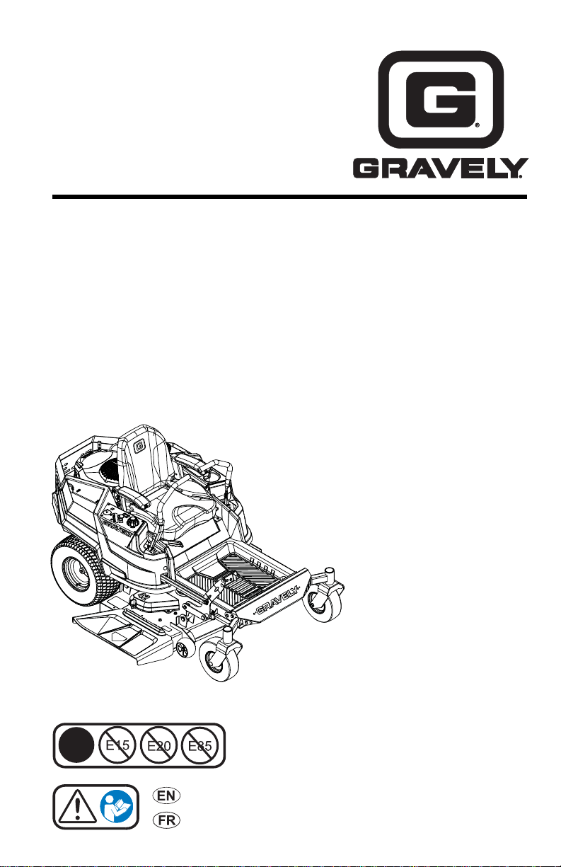
ZT X
ZT XL
Operator’s Manual
Manuel du Utilisateur
915172 – ZT X 42
(SN 020000 +)
™
™
Models
915202 – ZT XL 42
(SN 020000 +)
915174 – ZT X 52
(SN 020000 +)
915176 – ZT X 42 CARB
(SN 020000 +)
915200 – ZT XL 52
(SN 020000 +)
915204 – ZT XL 52
(SN 020000 +)
915206 – ZT XL 42
(SN 020000 +)
915216 – ZT XL 60
(SN 020000 +)
915218 – ZT XL 60
(SN 020000 +)
915230 – ZT X 52
(SN 020000 +)
915236 – ZT X 52 CARB
(SN 020000 +)
915238 – ZT XL 42 CARB
(SN 020000 +)
915240 – ZT XL 52 CARB
(SN 020000 +)
915242 – ZT XL 60 CARB
(SN 020000 +)
E10
ENGLISH
FRANÇAIS
05102200C • 2/17
Printed in USA
Page 2

TABLE OF CONTENTS
WELCOME . . . . . . . . . . . . . . . . . . . . . . 1
SAFETY. . . . . . . . . . . . . . . . . . . . . . . . . 2
Practices & Laws. . . . . . . . . . . . . . . . . . 2
Emission Control System. . . . . . . . . . . . 2
Required Operator Training. . . . . . . . . . 2
Safety Alert Symbol. . . . . . . . . . . . . . . . 2
Signal Words . . . . . . . . . . . . . . . . . . . . . 2
Safety Decals. . . . . . . . . . . . . . . . . . . . . 3
Safety Rules. . . . . . . . . . . . . . . . . . . . . . 6
CONTROLS AND FEATURES . . . . . . . 11
Ignition Ke y . . . . . . . . . . . . . . . . . . . . . . 12
Choke Control Knob. . . . . . . . . . . . . . . . 12
Throttle Control Lever . . . . . . . . . . . . . . 12
Power-Take-Off (PTO) Kn o b. . . . . . . . . 12
Hour Meter . . . . . . . . . . . . . . . . . . . . . . . 12
Height-of-Cut Dial . . . . . . . . . . . . . . . . . 12
Deck Lift Pedal. . . . . . . . . . . . . . . . . . . . 12
Seat Adjustment Lever. . . . . . . . . . . . . . 12
Parking Brake Lever . . . . . . . . . . . . . . . 13
Safety Interlock Sy stem. . . . . . . . . . . . . 13
Steering Levers . . . . . . . . . . . . . . . . . . . 13
Transaxle Bypass Levers. . . . . . . . . . . . 13
Anti-scalp Rollers. . . . . . . . . . . . . . . . . . 13
OPERATION . . . . . . . . . . . . . . . . . . . . . 13
Emergency Stopping . . . . . . . . . . . . . . . 13
Before Operating Unit . . . . . . . . . . . . . . 13
Start the Engine. . . . . . . . . . . . . . . . . . . 14
Operate Unit. . . . . . . . . . . . . . . . . . . . . . 14
Stop the Engine. . . . . . . . . . . . . . . . . . . 15
Move Unit Manually . . . . . . . . . . . . . . . . 15
Transport Unit . . . . . . . . . . . . . . . . . . . . 16
MAINTENANCE . . . . . . . . . . . . . . . . . . 16
Maintenance Schedule . . . . . . . . . . . . . 16
Service Parts . . . . . . . . . . . . . . . . . . . . . 16
Service Position. . . . . . . . . . . . . . . . . . . 20
Check Safety Interlo ck System . . . . . . . 20
Check Parking Brake. . . . . . . . . . . . . . . 20
Check Engine Oil. . . . . . . . . . . . . . . . . . 20
Check Tire Pressure . . . . . . . . . . . . . . . 21
Check Carbon Canister Filter. . . . . . . . . 21
Check Fasteners . . . . . . . . . . . . . . . . . . 21
Lubricate Unit. . . . . . . . . . . . . . . . . . . . . 21
Check Mower Blades. . . . . . . . . . . . . . . 22
Check Battery . . . . . . . . . . . . . . . . . . . . 23
Check Mower Belts . . . . . . . . . . . . . . . . 24
Hydraulic Oil. . . . . . . . . . . . . . . . . . . . . . 27
ADJUSTMENTS . . . . . . . . . . . . . . . . . . 28
Adjust Seat . . . . . . . . . . . . . . . . . . . . . . 28
Adjust Steering Levers. . . . . . . . . . . . . . 28
Adjust Unit to Track Straigh t . . . . . . . . . 29
Adjust Parking Brake Lev e r. . . . . . . . . . 30
Remove and Install Mower Deck. . . . . . 30
Adjust Mower Deck . . . . . . . . . . . . . . . . 32
TROUBLESHOOTING . . . . . . . . . . . . . 34
STORAGE. . . . . . . . . . . . . . . . . . . . . . . 36
Short-Term Storage. . . . . . . . . . . . . . . . 36
Long-Term Storage . . . . . . . . . . . . . . . . 36
Start-of-Season Preparation . . . . . . . . . 36
ACCESSORIES. . . . . . . . . . . . . . . . . . . 36
SPECIFICATIONS. . . . . . . . . . . . . . . . . 37
WARRANTY . . . . . . . . . . . . . . . . . . . . . 41
Page 3
WELCOME
Figure 1
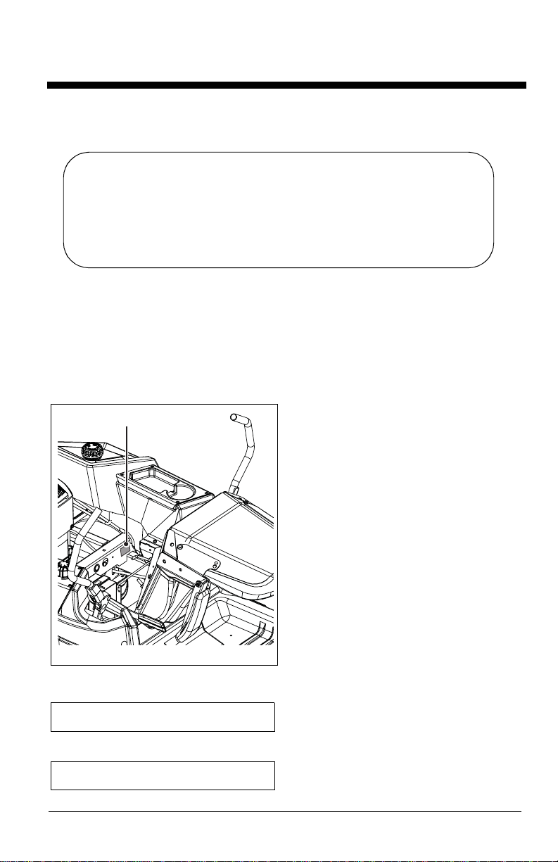
Model & Serial Number Label
Congratulations on your purchase and welcome to the Gravely family! Every machine in the
Gravely lineup is designed for long-lasting and unsurpassed performance. We are confident
your machine will be part of your f amily for many years to come.
Have Questions or Need Assistance?
gravely.custhelp.com • gravelymower.com
A parts manual for your unit is available for free download
Manual del operador español está disponible para su descarga gratuita o
or purchase at gravely.com.
compra en gravely.com.
PRODUCT REGISTRATION
You or the dealer you purchased the unit
from must register the product at the time of
purchase. Know the model and serial
numbers of your unit and register online at
gravely.com or return the registration card to
Ariens Company. See Figure 1 for label
location.
Record model number here.
MANUALS
Before operating or servicing the unit,
carefully and completely read the manuals
provided with the unit. They contain safety
instructions and important information about
unit controls.
The engine on this unit is covered by a
separate manual. Refer to the engine manual
for engine service recommendations.
Contact the engine manufacturer for a
replacement manual if necessary.
It is your responsibility to read and
understand all safety precautions and
instructions in the manuals. If you do not
understand or have difficulty following the
instructions, contact your Gravely dealer for
assistance. To locate your nearest dealer, go
to gravelymower.com.
DISCLAIMER
Gravely reserves the right to discontinue,
make changes to, and add improvement s
upon its products at any time without public
notice or obligation. The descriptions and
specifications contained in this manual were
in effect at printing. Equipment described in
this manual may be optional. Some
illustrations may not be applicable to your
unit.
Record serial number here.
EN - 1
Page 4
SAFETY
Read these safety rules and follow them
closely. Failure to follow these rules could
lead to loss of control of unit, severe personal
injury or death to you or bystanders, or resul t
in damage to property or the machine.
PRACTICES & LAWS
Practice usual and customary safe working
precautions. Learn applicable rules and laws
in your area. Always follow the practices set
forth in this manual.
EMISSION CONTROL SYSTEM
This equipment and/or its engine may include
exhaust and evaporative emissions control
system components required to meet U.S.
Environmental Protection Agency (EPA)
and/or California Air Resources Board
(CARB) regulations. Tampering with emission
controls and components by unauthorized
personnel may result in severe fines or
penalties. Emission controls and components
can only be adjusted by an Ariens Company
dealer or an authorized engine
manufacturer's service center. Contact your
Ariens Company Equipment Retailer
concerning emission controls and component
questions.
REQUIRED OPERATOR TRAINING
Read and understand the
Operator's Manual and decals
on the unit. This information is
for your safety and the proper
use of your equipment.
Failure to follow these
instructions and warnings may cause death
or serious injury. If you have purchased this
product from a Gravely dealer, the dealer can
provide you with training.
Familiarize yourself and any other operators
with all controls and the safe use of the
features of this unit. If you loan, rent or sell
this product to others, provide them with all
manuals.
If you have any questions, please call our
customer support line at 920-756-4688 or
contact us at www.gravely.com. Do not use
this equipment if, after reading the Operator's
Manual and the on-board decals, you have
any questions about the safe use of this
product.
WARNING: AVOID INJURY.
This cutting machine is capable
of amputating hands and feet
and throwing objects. Failure to
observe the safety instructions
in the manuals and on decals
could result in serious injury or
death.
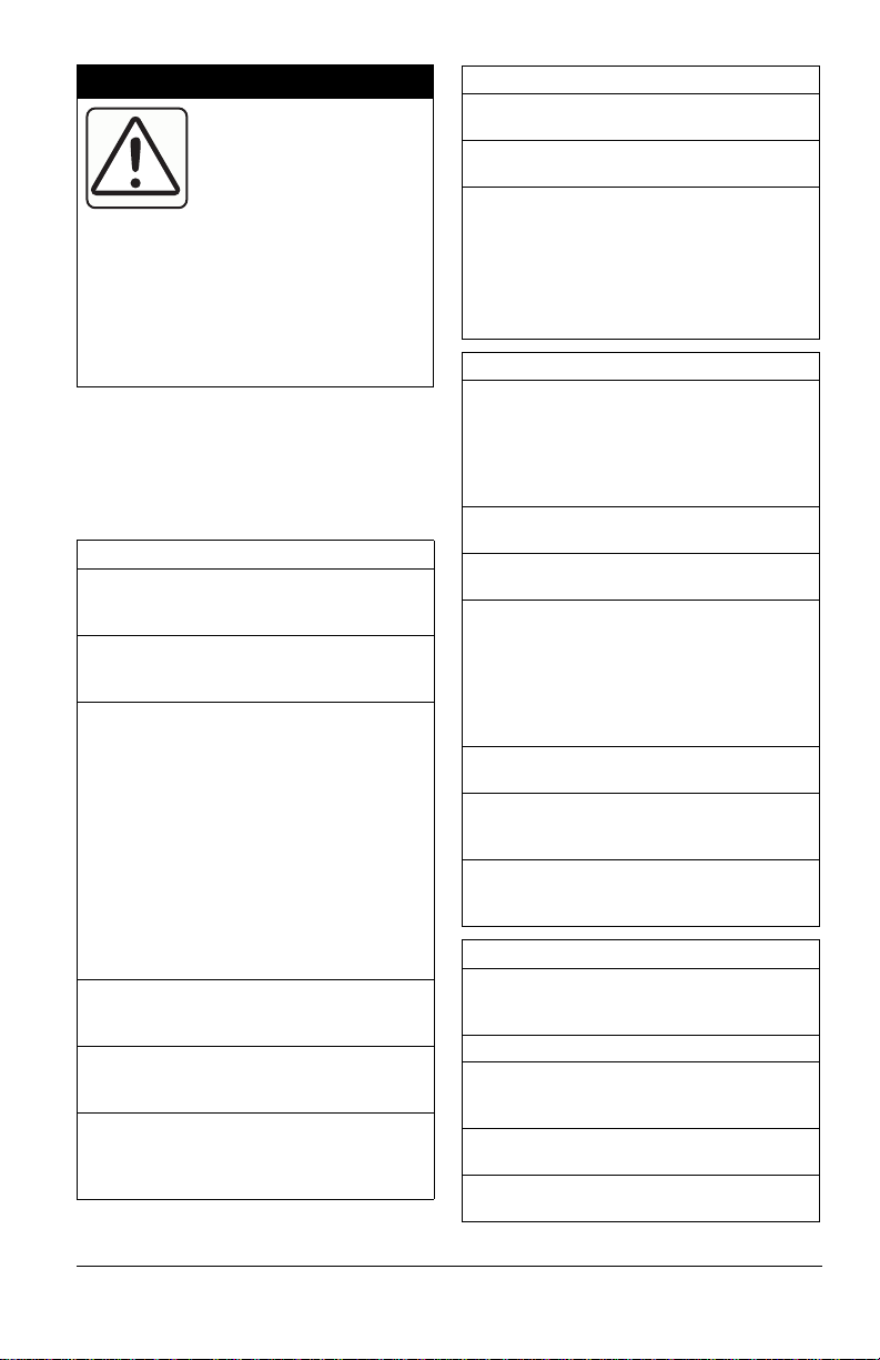
SAFETY ALERT SYMBOL
This is the safety alert symbol. It
means:
• ATTENTION!
• YOUR SAFETY IS
INVOLVED!
When you see this symbol:
• BECOME ALERT!
• OBEY THE MESSAGE!
SIGNAL WORDS
The safety alert symbol above and signal
words below are used on decals and in this
manual. Read and understand all safety
messages.
1. Danger
DANGER: Indicates an
IMMINENTLY HAZARDOUS
SITUATION! If not avoided,
WILL RESULT in death or
serious injury.
2. Warning
WARNING: Indicates a
POTENTIALLY HAZARDOUS
SITUATION! If not avoided,
COULD RESULT in death or
serious injury.
3. Caution
CAUTION: Indicates a
POTENTIALLY HAZARDOUS
SITUATION! If not avoided, MAY
RESULT in minor or moderate injury. It may also be used to alert
against unsafe practices.
4. Notice
NOTICE: Indicates information or procedures
that are considered important but not hazard
related. If not avoided property damage could
result.
EN - 2
Page 5
5. Important
Figure 2
1
3
4
5
7
6
2
2
6
8
IMPORTANT: Indicates general reference
information worthy of special attention.
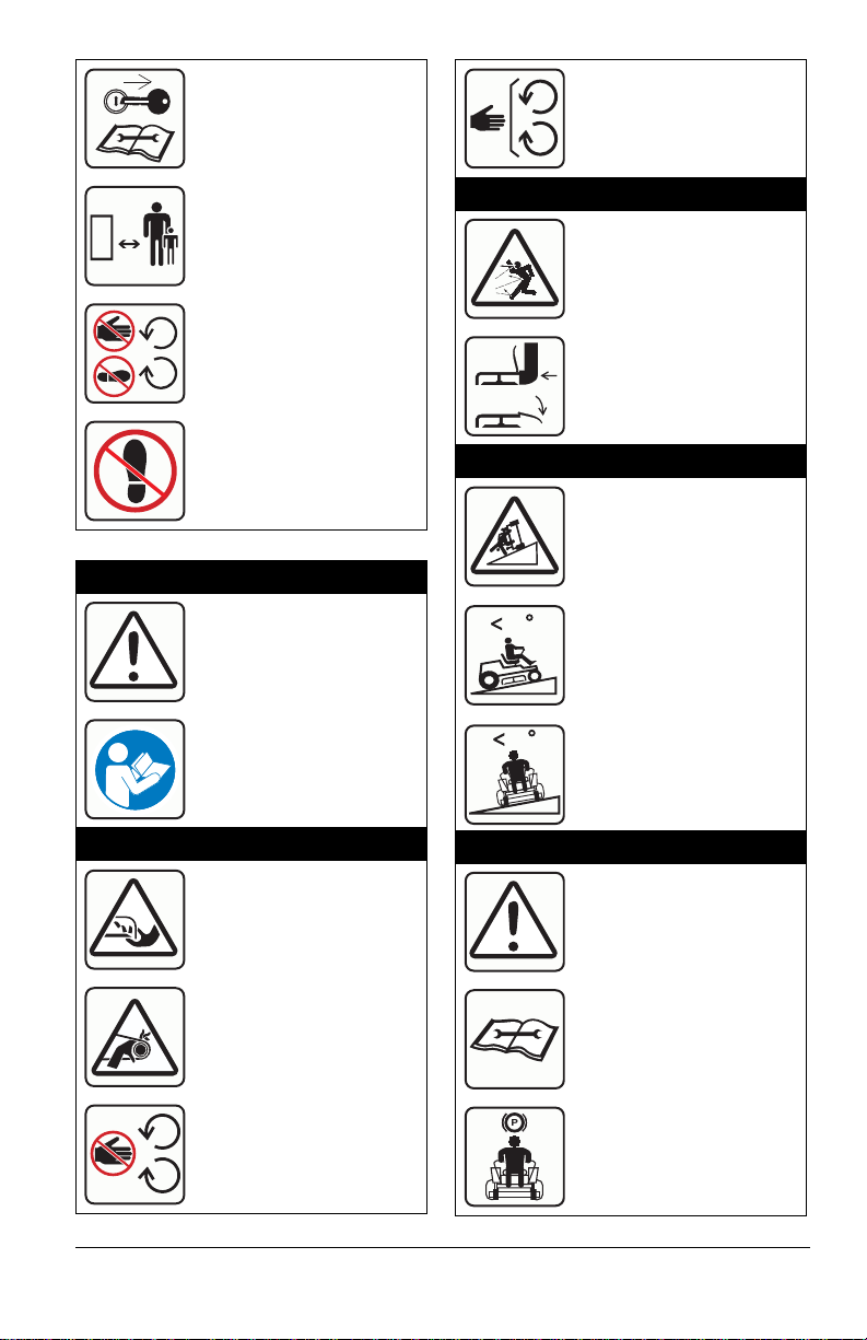
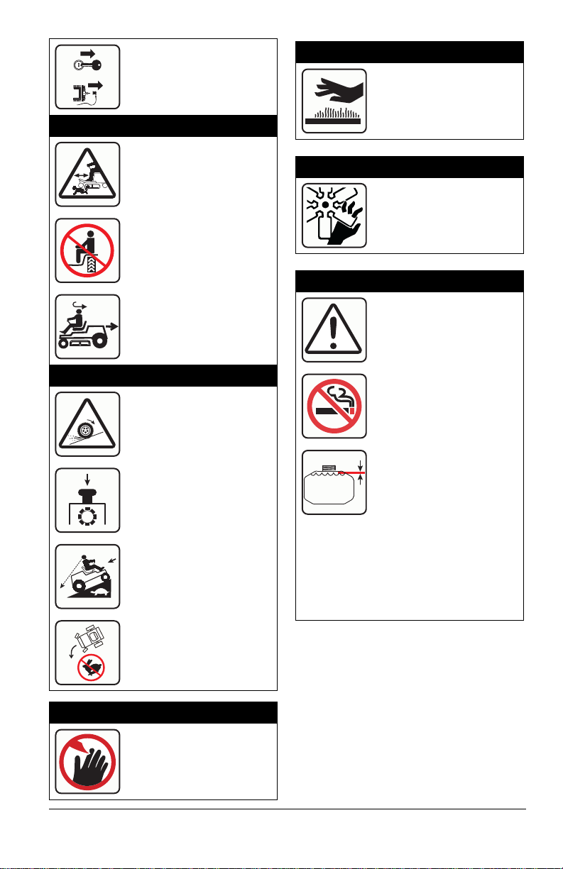
SAFETY DECALS
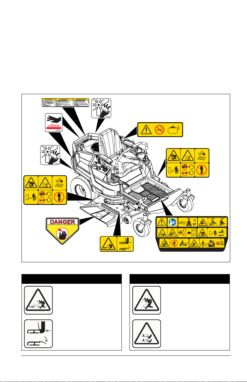
The safety decals on your machine are visual
reminders of the important safety information
in this manual. All messages on your unit
must be fully understood and carefully
followed. Safety decals on the machine are
explained below.
Safety Decal Locations
ALWAYS replace missing or damaged safety
decals. Replacement decal part numbers are
found in the parts manual for your machine
and may be ordered from your dealer.
See Figure 2 for safety decal locations.
Maximum tongue weight: 30 lbs.
KEEP HANDS and FEET AWAY
Safety Decal Descriptions
1. DANGER!
C
A
A
0
0
1
8
8
9
2
0
Discharge Hazard NEVER operate unit
without discharge chute in
operating position. Thrown
objects can cause injury or
damage.
A
07800536
P
07800537
2. DANGER!
Discharge Hazard - NEVER
direct discharge toward
people, pets or property.
Thrown objects can cause
injury or damage.
DO NOT operate mower
unless all guards are in
operating position or
bagger is attached.
Amputation Hazard NEVER stick hands or feet
under deck or shielded
areas.
EN - 3
Page 6
Shut off engine, remove key,
15
15
P
and read manual before
servicing or making
adjustments to unit.
Keep children and others
away from unit while unit is
in operation.
Keep feet and hands away
from all rotating or moving
parts.
Keep all guards and shields
in place.
3.2 Discharge Hazard
Discharge Hazard - NEVER
direct discharge toward
people, pets or property.
Thrown objects can cause
injury or damage.
DO NOT operate mower
unless all guards are in
operating position or bagger
is attached.
DO NOT step or stand in
this area.
3. DANGER!
DANGER!
Read and understand the
operator’s manual before
operating unit.
3.1 Amputation Hazard
To avoid amputation hazard
DO NOT put hands near
rotating blades.
To avoid amputation hazard
DO NOT put hands near
moving belts.
3.3 Tipping Hazard
Avoid tipping hazard.
DO NOT operate on slopes
over 15°.
DO NOT operate on slopes
over 15°.
3.4 Service Hazard
Before servicing unit do the
following:
Read owners manual before
servicing or making
adjustments to unit.
Keep hands away from all
rotating or moving parts.
EN - 4
Set parking brake.
Page 7
Remove key and disconnect
spark plug before servicing
or making adjustments to
unit.
3.5 Bystander Hazard
5. HOT PARTS!
DO NOT touch parts which
are hot from operation.
ALWAYS allow parts to cool.
DO NOT operate the unit in
the presence of bystanders.
DO NOT carry passengers.
Look behind when operating
the unit in reverse.
3.6 Loss of Traction Hazard
If loss of traction is
experienced do the
following:
Disengage PTO.
Proceed off slope slowly.
6. ROTATING PARTS!
AVOID INJURY. Stay clear
of rotating parts.
7. DANGER!
DANGER!
No smoking.
IMPORTANT: DO NOT
overfill. Fill fuel tank to
below bottom of filler neck.
WARNING: Overfilling may cause severe
damage to evaporative system!
• NEVER fill fuel tank when engine is
running, hot or unit is indoors. NEVER
overfill fuel tank.
• Replace fuel cap securely and clean up
spilled fuel.
4. DANGER!
DO NOT try to turn or speed
up.
ALWAYS keep hands and
feet away from discharge
chute.
EN - 5
Page 8
8. CAUTION!
• Maximum tongue weight:
30 lbs.
• Maximum trailer weight:
300 lbs.
• Do not use hitch with
bagger attached.
• Do not use on steep hills
or slopes.
• Do not park on hills when
trailer is attached.
• Do not use with any
ground engaging
equipment.
SAFETY RULES
The following safety instructions are based
on the B71.1 specifications of the American
National Standards Institute and ISO 5395 in
effect at the time of production.
Training
Read, understand, and follow all instructions
on the machine and in the manual(s) before
starting.
Be sure the area is clear of byst anders and
pets before operating. Stop machine if
anyone enters the area.
Improper use of power equipment can cause
serious permanent injury or death to the
operator or a bystander.
Understand:
• How to operate all controls
• The functions of all controls
• How to STOP in an emergency
• Braking and steering characteristics
• Turning radius and clearances
If the operator or the mechanic cannot read
the manual, it is the owner’s responsibility to
explain it to them.
ALWAYS train any inexperienced operators
and require them to read and understand all
manuals and decals.
Only allow responsible adults, who are
familiar with the instructions, to operate this
machine.
Only the operator can prevent and is
responsible for accidents or injuries
occurring to themselves, other people or
property.
Operator Age
DO NOT allow children under the age of 18
to operate any outdoor power equipment.
Local regulations may restrict the age of the
operator.
Data indicates operators age 60 years and
above are involved in a large percentage of
riding mower-related injuries.
These operators should evaluate their ability
to operate the riding mower safely enough to
protect themselves and others from serious
injury.
Children
Tragic accidents can occur if the operator is
not alert to the presence of children.
Children are often attracted to the machine
and the mowing activity. NEVER assume
that children will remain where you last saw
them.
Be alert and turn machine off if a child enters
the area.
Before and while backing, look behind and
down for small children.
NEVER carry children, even with the
blade(s) shut off. They may fall off and be
seriously injured or interfere with safe
machine operation. Children who have been
given rides in the past may suddenly appear
in the mowing area for another ride and be
run over or backed over by the machine.
NEVER allow children to operate the
machine.
Use extreme care when approaching blind
corners, shrubs, trees or other objects that
may block your view of a child.
Keep children out of the mowing area and in
the watchful care of a responsible adult
other than the operator.
Personal Protection
DO NOT wear loose clothing or jewelry and
tie back hair that may get caught in rotating
parts.
Wear adequate outer garments.
NEVER wear open sandals or canvas shoes
during operation. Wear adequate safety
gear, protective gloves and footwear.
Wear proper footwear to improve footing on
slippery surfaces.
ALWAYS wear eye and ear protection when
operating machine.
EN - 6
Page 9
Before Operating
Keep all nuts and bolts tight to be sure the
equipment is in safe working condition.
Maintain the machine to be in compliance
with the maintenance schedule.
Clean grass and debris from unit, especially
from around muffler and engine, to help
prevent fires.
Check parking brake operation frequently.
Adjust and service as required.
Inspect unit before each use for missing or
damaged decals and shields, correctly
operating safety interlock system, and
deterioration of grass catchers. Replace or
repair as needed.
Ensure Safety Interlock System is
functioning properly. DO NOT operate unit if
safety interlock is damaged or disabled.
Start and operate unit only when seated in
operator’s position. Steering control levers
must be in neutral, PTO disengaged and
parking brake set when starting engine.
NEVER interfere with the intended function
of a safety device or reduce the protection
provided by a safety device. Check their
proper operation regularly.
Keep machine free of grass, leaves or other
debris build-up. Clean up oil or fuel spillage
and remove any fuel-soaked debris.
Operation
Be sure the area is clear of byst anders
before operating. Stop machine if anyone
enters the area.
NEVER operate machine in a closed or
poorly-ventilated area.
ALWAYS maintain unit in safe operating
condition. Damaged or worn out muffler can
cause fire or explosion.
This product is equipped with an internal
combustion type engine. DO NOT use unit
on or near any unimproved, forest-covered
or brush-covered land unless exhaust
system is equipped with a spark arrester
meeting applicable local, state or federal
laws. A spark arrester, if it is used, must be
maintained in effective working order by
operator.
DO NOT operate machine while feeling
tired, ill or under the influence of alcohol or
other drugs.
DO NOT put hands or feet near rotating
parts or under the machine. Keep clear of
the discharge opening at all times.
DO NOT touch parts which are hot. Allow
parts to cool.
DO NOT operate machine without the entire
grass catcher, discharge guard or other
safety devices in place and working.
ALWAYS keep hands and feet away from all
pinch points.
Avoid slippery surfaces. ALWAYS be sure of
your footing.
NEVER carry passengers.
NEVER direct discharged material toward
anyone. Avoid discharging material against
a wall or obstruction. Material may ricochet
back toward the operator. Stop the blade(s)
when crossing gravel surfaces.
NEVER engage PTO when attachment,
including mower blades, is not in use.
ALWAYS turn off power to attachment when
not in active use such as traveling or
crossing driveways.
ALWAYS disengage PTO, stop unit and
engine, remove key, engage parking brake
and allow moving parts to stop before
leaving operator’s position.
NEVER engage PTO while raising the
attachment, including mower blades, or
when attachment is in the raised position.
Keep safety devices or guards in place and
functioning properly. NEVER modify or
remove safety devices.
DO NOT mow in reverse unless absolutely
necessary. ALWAYS look down and behind
before and while backing.
Stop engine before removing grass catcher
or unclogging chute.
Slow down before turning.
If you strike a foreign object, stop and
inspect the machine. Repair, if necessary,
before restarting.
NEVER leave a running machine
unattended. ALWAYS turn off blade(s), set
parking brake, stop engine and remove key
before dismounting.
Disengage blade(s) when not mowing. Shut
off engine and wait for all parts to come to a
complete stop before cleaning the machine,
removing the grass catcher, or unclogging
the discharge guard.
Know the weight of loads. Limit loads to
those you can safely control and the unit can
safely handle.
EN - 7
Page 10
Operating Conditions
Lightning can cause severe injury or death.
If lightning is seen or thunder is heard in the
area, do not operate the machine, see
shelter.
ALWAYS check overhead and side
clearances carefully before operation.
Watch for traffic when operating near or
crossing roadways.
Clear the area of objects such as rocks,
wire, toys, etc., which could be thrown by the
blades.
Check for weak spots on docks, ramps or
floors. Avoid uneven work areas and rough
terrain. Stay alert for hidden hazards or
traffic.
Use care when approaching blind corners,
shrubs, trees or other objects that may
obscure vision.
Dust, smoke, fog, etc. can reduce vision and
cause an accident.
Operate machine only in daylight or good
artificial light.
Slope Operation
Slopes are a major factor rel ated to loss of
control and tip-over accidents, which can
result in severe injury or death. Operation on
all slopes requires extra caution. If you
cannot back up the slope or if you feel
uneasy on it, DO NOT mow it.
DO NOT operate on slopes of more t han
15°.
Mow up and down slopes, not across.
ALWAYS keep the machine in gear when
going down slopes. DO NOT shift to neutral
and coast downhill.
Watch for holes, ruts, bumps, rocks, or other
hidden objects. Uneven terrain could
overturn the machine. Tall grass can hide
obstacles.
DO NOT mow on moist or wet grass. Tires
may lose traction causing a loss of control.
Use extra care while operating machine with
grass catchers or other attachments; they
can affect the stability of the machine. DO
NOT use on steep slopes.
Keep all movements on the slope slow and
gradual. DO NOT make sudden changes in
speed or direction, which could cause the
machine to roll over.
Avoid starting, stopping, or turning on a
slope. If the tires lose traction, disengage
the blade(s) and proceed slowly straight
down the slope.
Operation on slopes may lead to loss of
steering control. When operating on slopes
be prepared to react to an emergency
situation:
• Return steering levers to neutral position.
• Immediately set parking brake.
• Turn off PTO and engine.
DO NOT try to stabilize the machine by
putting your foot on the ground.
DO NOT park on slopes unless necessary.
When parking on slope ALWAYS chock or
block wheels. ALWAYS set parking brake.
Choose a low ground speed so you will not
have to stop or shift while on a slope.
DO NOT mow near drop-offs, ditches, or
embankments. The machine could suddenly
roll over if a wheel goes over the edge or if
the edge caves in.
DO NOT bypass transmission or allow
transmission to free-wheel when on a slope.
Fuel
To avoid personal injury or property damage,
use extreme care in handling gasoline.
Gasoline is extremely flammable and the
vapors are explosive.
Ethanol blends must not exceed E10. Higher
ethanol content may cause your
machine to run hotter and damage your
engine.
Replace fuel cap securely and clean up
spilled fuel before starting engine.
Extinguish all cigarettes, cigars, pipes and
other sources of ignition.
Use only an approved gasoline container.
NEVER store the machine or fuel container
where there is an open flame, spark or pilot
light such as on a water or space heater or
other appliances.
NEVER fill containers inside a vehicle or on
a truck or trailer bed with a plastic liner.
ALWAYS place containers on the ground
away from your vehicle before filling.
NEVER fuel the machine indoors.
NEVER remove gas cap or add fuel with the
engine running. Allow engine to cool before
fueling.
EN - 8
Page 11
Fuel is highly flammable and its vapors are
explosive. Handle with care. Use only an
approved gasoline container with an
appropriately-sized dispensing spout.
NO smoking, NO sparks, NO flames.
Remove gas-powered equipment from the
trailer and refuel it on the ground. If this is
not possible, then refuel such equipment
with a portable container, rather than from a
gasoline dispenser nozzle.
Keep the nozzle in contact with the rim of
the fuel tank or container opening at all
times until the fueling is complete. DO NOT
use a nozzle lock-open device.
NEVER overfill fuel tank. Replace gas cap
and tighten securely.
If fuel is spilled on clothing, change clothing
immediately.
Towing
Follow the manufacturer’s recommendations
for weight limits for towed equipment and
towing on slopes.
NEVER allow children or others in or on
towed equipment.
Tow only with a machine that has a hi tch
designed for towing. DO NOT attach towed
equipment except at the hitch point.
On slopes, the weight of the towed
equipment may cause loss of traction and
loss of control.
Travel slowly and allow extra distance to
stop.
Accessories
Follow the manufacturer’s recommendation
for wheel weights or counterweights.
Check grass catcher components and the
discharge guard frequently and replace with
the manufacturer’s recommended parts,
when necessary.
Use only Ariens Company-recommended
attachments that are appropriate to your use
and can be used safely in your application.
Batteries
Avoid electric shock. Objects contacting
both battery terminals at the same time may
result in injury and unit damage. DO NOT
reverse battery connections.
Reverse connections may result in sparks
which can cause serious injury. ALWAYS
connect positive (+) lead of charger to
positive (+) terminal, and negative (-) l ead to
negative (-) terminal.
ALWAYS disconnect negative (-) cable
FIRST and positive (+) cable SECOND.
ALWAYS connect positive (+) cable FI RST,
and negative (-) cable SECOND.
Explosive gases from battery can cause
death or serious injury. Poisonous battery
fluid contains sulfuric acid and its contact
with skin, eyes or clothing can cause severe
chemical burns.
No flames, No sparks, No smoking near
battery.
ALWAYS wear safety glasses and protective
gear near battery. Use insulated tools.
ALWAYS keep batteries out of reach of
children.
Battery posts, terminals and related
accessories contain lead and lead
compounds, chemicals known to the state of
California to cause cancer and reproductive
harm. Wash hands after handling.
Service
The use of non-genuine replacement parts
or accessories could adversely affect
machine operation and safety.
Do not change engine governor setting or
overspeed the engine.
Maintain or replace safety and instruction
labels as necessary.
Keep unit free of debris. Clean up oil or fuel
spills.
ALWAYS block wheels and know all jack
stands are strong and secure and will hold
weight of unit during maintenance.
Release any pneumatic or hydraulic
pressure from components slowly.
NEVER attempt to make any adjustments to
unit while engine is running (except where
specifically recommended). Stop engine,
remove key and spark plug wire and wait for
all moving parts to stop before servicing or
cleaning.
Lower cutting deck unless a positive
mechanical lock is used.
Allow engine to cool before servicing.
Moving parts can cut or amputate fingers or
a hand. On multiblade mowers, rotation of
one blade will cause all blades to rotate.
EN - 9
Page 12

NEVER weld or straighten mower blades.
NEVER make adjustments or repairs with
the engine running.
Mower blades are sharp. Wrap the blade or
wear gloves, and use extra caution when
servicing them.
ALWAYS keep body and hands away from
pin holes or nozzles which eject hydraulic
fluid under pressure.
Transporting Unit
Use extra care when loading or unloading
the machine into a trailer or truck.
Secure unit chassis to transport vehicle.
NEVER secure from rods or linkages that
could be damaged.
DO NOT transport machine while engine is
running.
ALWAYS turn off power to attachment and
shut off fuel when transporting unit.
Storage
NEVER store unit with fuel in fuel tank inside
a building where any ignition sources are
present.
Keep machine free of grass, leaves or other
debris build-up. Clean up oil or fuel spillage
and remove any fuel-soaked debris. Allow
machine to cool before storing.
For extended storage, close fuel shut off
valve and clean unit thoroughly. See engine
manual for proper storage.
EN - 10
Page 13
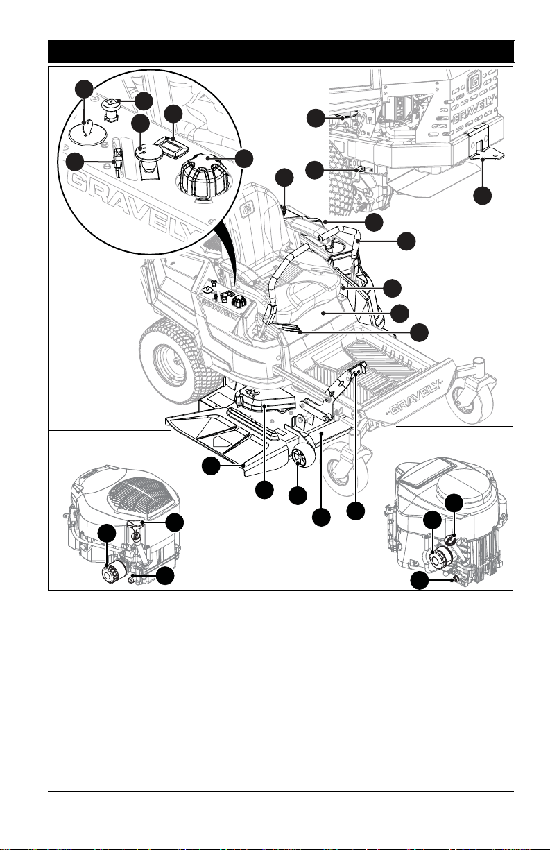
CONTROLS AND FEATURES
Figure 3
9
19
16
12
22
20
10
8
11
6
18
21
14
15
17
2
1
13
Models 915204, 915206,
915218, 915230, 915236 ,
915238, 915240, 915242
Models 915172, 915174,
915176, 915200, 915202,
915216
7
3
4
5
3
4
5
23
1. Fuel Tank and Cap
2. Fuel Level Window
3. Oil Filter
4. Oil Drain
5. Engine Oil Dipstick
6. Ignition Key
7. Choke Control Knob (Models 915204,
915206, 915218, 915230, 915236,
915238, 915240, 915242)
8. Throttle Control Lever
9. Power Take-off (PTO) Knob
10. Hour Meter
11. Height-of-Cut Dial
12. Deck Lift Pedal
13. Seat Adjustment Lever
14. Parking Brake Lever
15. Belt Guard (2)
16. Mower Deck
17. Steering Lever (2)
18. Towing / Trailer Hitch
19. Discharge Chute
20. Anti-Scalp Roller (2)
21. Transaxle Bypass Lever (2)
22. Battery (Under Seat)
23. Carbon Canister (Models 915176,
915236, 915238, 915240, 915242)
EN - 11
Page 14
WARNING: AVOID INJURY.
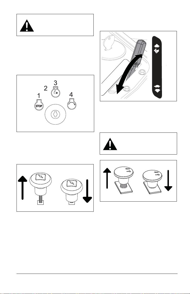
Figure 4
Off
On
Start
On With
Headlights
(If Equipped)
Figure 5
Choke On
Choke Off
Figure 6
Fast
Slow
Figure 7
Blades Off
Blades On
Read and understand the
entire Safety section before
proceeding.
See Figure 3 for all controls and features
locations.
IGNITION KEY
See Figure 4.
Controls power to the engine. The key cannot
be removed when in run position.
THROTTLE CONTROL LEVER
See Figure 6.
Controls engine speed.
POWER-TAKE-OFF (PTO) KNOB
See Figure 7.
Controls power to mower blades. The engine
will not start with the PTO knob in the on
position.
CHOKE CONTROL KNOB
Models 915204, 915206, 915218, 915230,
915236, 915238, 915240, 915242
See Figure 5.
Controls airflow to the engine.
WARNING: AVOID INJURY.
Blades will not immediately
stop after pushing PTO knob
down to off position.
HOUR METER
Hour meter measures engine runtime and
cannot be reset.
HEIGHT-OF-CUT DIAL
Sets the mower height of cut.
DECK LIFT PEDAL
Raises or lowers mower deck.
SEAT ADJUSTMENT LEVER
Unlocks seat to allow operator to move seat
forward or backward and then lock in desired
position.
EN - 12
Page 15
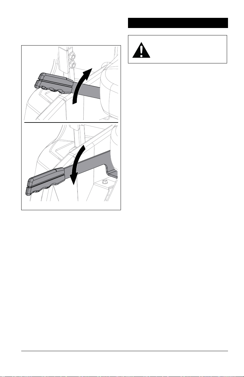
PARKING BRAKE LEVER
Figure 8
Brake Released
(Off)
Parking Brake
Engaged (On)
See Figure 8.
Controls the parking brake. The engine will
not start with brake in the off position.
SAFETY INTERLOCK SYSTEM
Monitors the interaction of various unit
features for operator safety.
STEERING LEVERS
Control the direction and speed of unit. The
levers gradually return to neutral when
released and are locked in neutral when
parking brake is set.
TRANSAXLE BYPASS LEVERS
Control the transaxles so unit may be moved
with the engine off.
ANTI-SCALP ROLLERS
Help prevent the deck from contacting the
ground and scalping the lawn when passing
over a high spot.
OPERATION
WARNING: AVOID INJURY.
Read and understand the
Safety section before
proceeding.
IMPORTANT: All references to left, right, front
or rear are given from the perspect ive of
operator in operator’s position, facing the
direction of forward travel.
EMERGENCY STOPPING
1. Move steering levers to neutral position.
2. Engage parking brake.
3. Push PTO knob down to off position.
4. Turn ignition key to off position and
remove key from ignition.
BEFORE OPERATING UNIT
1. Check fuel level and add fuel if needed.
IMPORTANT: Use fresh unleaded fuel with
an octane rating of at least 87. DO NOT use
E85 blended fuels; the engine is not E20 /
E30 / E85 compatible. The maximum
recommended ethanol content is 10%.
Gravely recommends using a quality fuel
stabilizer in all fuel. See Short-Term Storage
on page 36.
2. Check engine oil level and add oil if
needed. Refer to engine manual.
3. Check condition of air cleaner. Refer to
engine manual.
4. Check function of the Safety Interlock
System by performing the tests in Check
Safety Interlock System on page 20.
Contact your Gravely dealer for repair if
any of the tests fail.
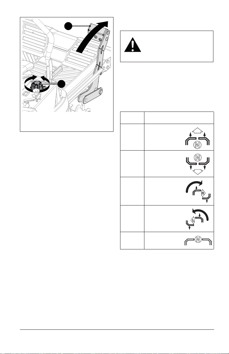
5. Set cutting height. See Figure 9.
a. Depress and hold deck lift pedal in
forward position.
b. Rotate height-of-cut dial to desired
setting.
c. Slowly return deck lift pedal to resting
position.
EN - 13
Page 16
START THE ENGINE
Figure 9
1. Deck Lift Pedal
2. Height-of-Cut Dial
1
2
1. Push PTO knob down to off position.
2. Move steering levers to neutral position.
3. Engage parking brake.
4. Models 915204, 915206, 915218,
915230, 915236, 915238, 915240,
915242: If engine is cold, pull choke knob
up to on position. If engine is warm or hot,
turn choke off.
5. Set throttle to slow speed.
6. Insert ignition key and turn to start
position. Release key when engine starts.
IMPORTANT: Do not operate the starter for
more than 10 seconds at a time. If the engine
does not start, allow a 60-second cool down
period between starting attempts.
7. Models 915204, 915206, 915218,
915230, 915236, 915238, 915240,
915242: If choke is on, wait a few
seconds after engine starts and then push
choke knob down to off position.
IMPORTANT: Make sure choke is completely
off. Engine will not run smoothly using partial
choke.
OPERATE UNIT
1. Release parking brake.
WARNING: AVOID INJURY.
Move the steering levers
slowly and keep the throttle at
slow speed until you learn how
to operate the unit.
2. Set throttle to slow speed.
3. Pull PTO knob up to on position.
IMPORTANT: Never engage the PTO if the
mower is plugged with grass or other
material. This may cause damage to the
electric clutch.
4. Move steering levers to begin mowing.
Direction
of Travel
Forward Push both levers
Reverse Pull both levers
Right Turn Push left lever
Left Turn P ush right lever
Stop Return both
5. Move throttle control lever to fast.
IMPORTANT: Aggressive turning can scuff or
damage lawns. Always keep both wheels
rotating when making sharp turns. DO NOT
make turns with inside wheel completely
stopped. For minimum turning radius, slowly
reverse inside wheel while moving outside
wheel slowly forward.
Lever Position
forward from
neutral position.
backward from
neutral position.
farther forward
than the right
lever.
farther forward
than the left lever.
levers to neutral
position.
EN - 14
Page 17
For Best Mowing Results
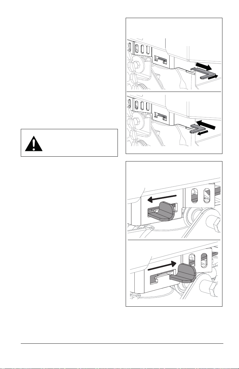
Figure 10
Front Position
Rear Position
Models 915200, 915202, 915204, 915206,
915216, 915218, 915238, 915240, 915242
Figure 11
Rear Position
Front Position
Models 915172, 915174, 915176,
915230, 915236
• Cut grass when it is dry.
• Keep mower blades sharp.
• Keep mower deck properly leveled.
• Do not set height of cut too low. For very
tall grass, mow twice.
• Do not travel too fast.
• Mow with the engine set at full throttle.
• When mulching, only remove 1/3 of grass
length per cutting. Do not cut more than
2.5 cm (1") at any one time.
• Discharge clippings into areas already cut.
• Vary cutting pattern with each mowing.
• Do not allow grass or debris to collect
inside of mower deck. Clean after each
use.
STOP THE ENGINE
WARNING: AVOID INJURY.
Wait for all moving parts to
stop before leaving operator’s
position.
1. Move steering levers to neutral position.
2. Engage parking brake.
3. Push PTO knob down to off position.
4. Set throttle to slow speed.
5. Turn ignition key to off position and
remove key from ignition.
MOVE UNIT MANUALLY
See Figure 10 and See Figure 11.
IMPORTANT: There is one transaxle bypass
lever on each side of unit. Ensure that both
levers are fully in front or rear position.
• To disengage the transaxles and move unit
with the engine off, place both bypass
levers in the rear position.
• To engage transaxles and operate unit
normally, place both bypass levers in the
front position.
EN - 15
Page 18
TRANSPORT UNIT
1. Stop engine, set parking brake and
remove key from ignition.
2. Secure unit chassis to transport vehicle.
NOTICE: NEVER secure from rods or
linkages that could be damaged.
MAINTENANCE
WARNING: AVOID INJURY.
Read and understand the
Safety section before
proceeding.
Your Gravely dealer can provide service and
adjustments to keep your unit operating at
peak efficiency.
Contact an authorized engine manufacturer’s
service center for engine service.
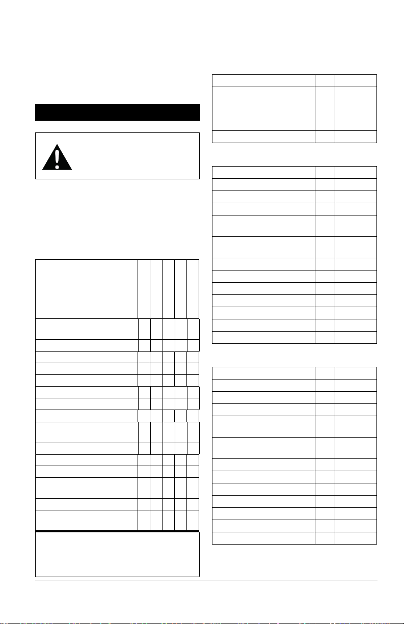
MAINTENANCE SCHEDULE
Service Performed
Check Safety Interlock
System
Check Parking Brake •
Check Engine Oil * •
Change Engine Oil *+
Check Tire Pressure •
Check Mower Blades •
Check Battery •
Clean Battery •
Check Carbon Canister
Filter
Check Air Filter * •
Check Fasteners •
Lubricate Unit •
Clean Engine Cooling
System*
Check Belts •
Change Hydraulic Oil and
Filter (XL Models) **
* Refer to engine manual for instructions.
+ Use tubing included in literature pack to
drain engine oil.
**Change after first 75 hours of operation.
Each Use
•
Every 25 hrs.
Every 50 hrs.
Every 100 hrs.
•
•
SERVICE PARTS
See your Gravely dealer to purchase service
parts for your unit.
Common Service Parts
Description Qty. P art No.
Fuel Stabilizer – 118 ml
(4 oz)
• Except Canada
• For Canada Only
Seat Switch 1 02754100
Model 915172
Description Qty. P art No.
Drive Belt 1 07200718
Mower Belt 1 07200523
Mower Blade 1 04769800
Front Wheel and Tire
Assembly
Drive Wheel and Tire
Assembly
Armrest Kit – Left 1 51528800
Armrest Kit – Right 1 51528900
Spark Plug 1 20934100
Fuel Filter 1 21539500
Oil Filter 1 21550800
Every 400 hrs.
Air Filter 1 21555300
Pre-Cleaner 1 21555400
Model 915174
Description Qty. P art No.
Drive Belt 1 07200718
Mower Belt 1 07200023
Mower Blade 1 04771200
Front Wheel and Tire
Assembly
Drive Wheel and Tire
Assembly
Armrest Kit – Left 1 51528800
Armrest Kit – Right 1 51528900
Spark Plug 1 20934100
Fuel Filter 1 21539500
Oil Filter 1 21550800
•
Air Filter 1 21555300
Pre-Cleaner 1 21555400
A/R
1 07101127
1 07101130
1 07101127
1 07101130
04730300
04742400
EN - 16
Page 19
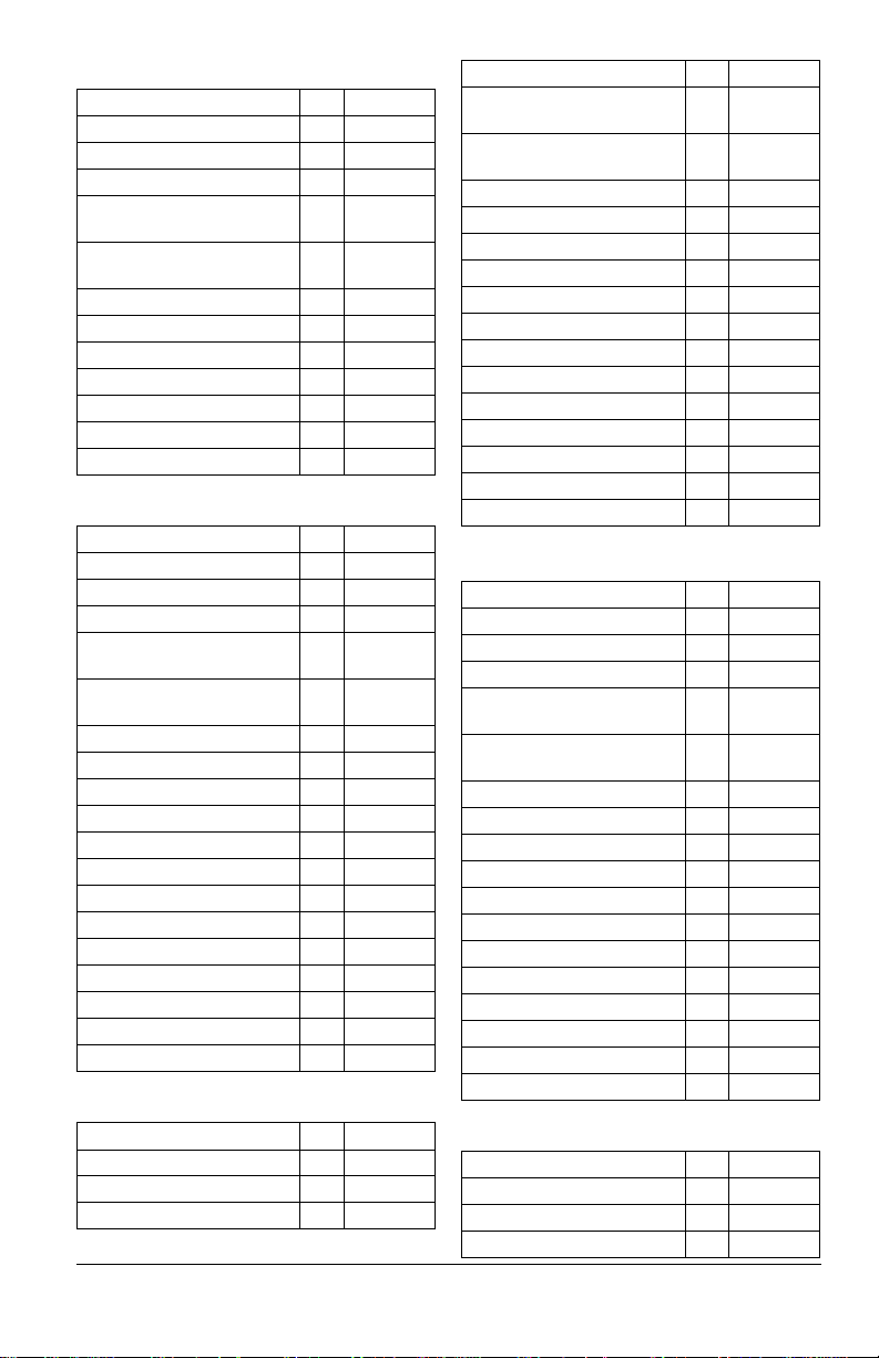
Model 915176
Description Qty. Part No.
Drive Belt 1 07200718
Mower Belt 1 07200523
Mower Blade 1 04769800
Front Wheel and Tire
Assembly
Drive Wheel and Tire
Assembly
Armrest Kit – Left 1 51528800
Armrest Kit – Right 1 51528900
Spark Plug 1 20934100
Fuel Filter 1 21539500
Oil Filter 1 21550800
Air Filter 1 21555300
Pre-Cleaner 1 21555400
Model 915200
Description Qty. Part No.
Drive Belt 1 07200724
Mower Belt 1 07200023
Mower Blade 1 04771200
Front Wheel and Tire
Assembly
Drive Wheel and Tire
Assembly
Armrest Pad – Left 1 21559500
Armrest Pad – Right 1 21559700
Armrest Kit – Left 1 51530000
Armrest Kit – Right 1 51530100
Seatback Cushion 1 21560600
Seat Bottom Cushion 1 21560800
Hydraulic Oil Filter 2 21545100
Hydraulic Oil (32 oz) AR 00057100
Spark Plug 1 20934100
Fuel Filter 1 21539500
Oil Filter 1 21550800
Air Filter 1 21555300
Pre-Cleaner 1 21555400
Model 915202
Description Qty. Part No.
Drive Belt 1 07200804
Mower Belt 1 07200523
Mower Blade 1 04769800
1 07101127
1 07101130
1 07101105
1 07101203
Description Qty. P art No.
Front Wheel and Tire
Assembly
Drive Wheel and Tire
Assembly
Armrest Pad – Left 1 21559500
Armrest Pad – Right 1 21559700
Armrest Kit – Left 1 51530000
Armrest Kit – Right 1 51530100
Seatback Cushion 1 21560600
Seat Bottom Cushion 1 21560800
Hydraulic Oil Filter 2 21545100
Hydraulic Oil (32 oz) AR 00057100
Spark Plug 1 20934100
Fuel Filter 1 21539500
Oil Filter 1 21550800
Air Filter 1 21555300
Pre-Cleaner 1 21555400
Model 915204
Description Qty. P art No.
Drive Belt 1 07200724
Mower Belt 1 07200023
Mower Blade 1 04771200
Front Wheel and Tire
Assembly
Drive Wheel and Tire
Assembly
Armrest Pad – Left 1 21559500
Armrest Pad – Right 1 21559700
Armrest Kit – Left 1 51530000
Armrest Kit – Right 1 51530100
Seatback Cushion 1 21560600
Seat Bottom Cushion 1 21560800
Hydraulic Oil Filter 2 21545100
Hydraulic Oil (32 oz) AR 00057100
Spark Plug 1 21536100
Fuel Filter 1 21548101
Oil Filter 1 21548100
Air Filter 1 21548000
Model 915206
Description Qty. P art No.
Drive Belt 1 07200724
Mower Belt 1 07200523
Mower Blade 1 04769800
1 07101105
1 07101122
1 07101105
1 07101203
EN - 17
Page 20
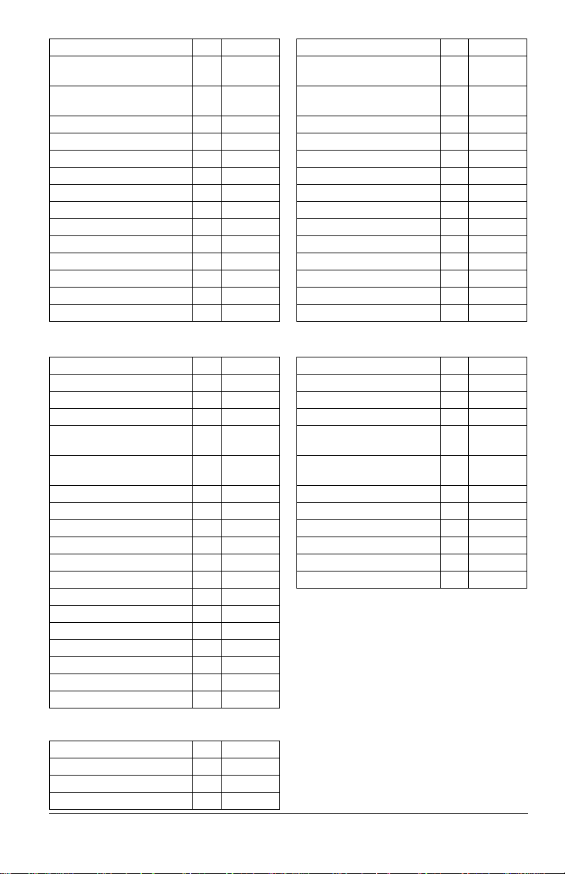
Description Qty. Part No.
Front Wheel and Tire
1 07101105
Assembly
Drive Wheel and Tire
1 07101122
Assembly
Armrest Pad – Left 1 21559500
Armrest Pad – Right 1 21559700
Armrest Kit – Left 1 51530000
Armrest Kit – Right 1 51530100
Seatback Cushion 1 21560600
Seat Bottom Cushion 1 21560800
Hydraulic Oil Filter 2 21545100
Hydraulic Oil (32 oz) AR 00057100
Spark Plug 1 21536100
Fuel Filter 1 21548101
Oil Filter 1 21548100
Air Filter 1 21548000
Description Qty. P art No.
Front Wheel and Tire
1 07101105
Assembly
Drive Wheel and Tire
1 07101213
Assembly
Armrest Pad – Left 1 21559500
Armrest Pad – Right 1 21559700
Armrest Kit – Left 1 51530000
Armrest Kit – Right 1 51530100
Seatback Cushion 1 21560600
Seat Bottom Cushion 1 21560800
Hydraulic Oil Filter 2 21545100
Hydraulic Oil (32 oz) AR 00057100
Spark Plug 1 21536100
Fuel Filter 1 21548101
Oil Filter 1 21548100
Air Filter 1 21548000
Model 915216
Description Qty. Part No.
Drive Belt 1 07200724
Mower Belt 1 07200804
Mower Blade 1 04965000
Front Wheel and Tire
1 07101105
Assembly
Drive Wheel and Tire
1 07101213
Assembly
Armrest Pad – Left 1 21559500
Armrest Pad – Right 1 21559700
Armrest Kit – Left 1 51530000
Armrest Kit – Right 1 51530100
Seatback Cushion 1 21560600
Seat Bottom Cushion 1 21560800
Hydraulic Oil Filter 2 21545100
Hydraulic Oil (32 oz) AR 00057100
Spark Plug 1 20934100
Fuel Filter 1 21539500
Oil Filter 1 21550800
Air Filter 1 21555300
Pre-Cleaner 1 21555400
Model 915218
Description Qty. Part No.
Drive Belt 1 07200724
Mower Belt 1 07200804
Mower Blade 1 04965000
Model 915230
Description Qty. P art No.
Drive Belt 1 07200718
Mower Belt 1 07200023
Mower Blade 1 04771200
Front Wheel and Tire
1 07101127
Assembly
Drive Wheel and Tire
1 07101130
Assembly
Armrest Kit – Left 1 51528800
Armrest Kit – Right 1 51528900
Spark Plug 1 21536100
Fuel Filter 1 21539500
Oil Filter 1 21548100
Air Filter 1 21548000
EN - 18
Page 21
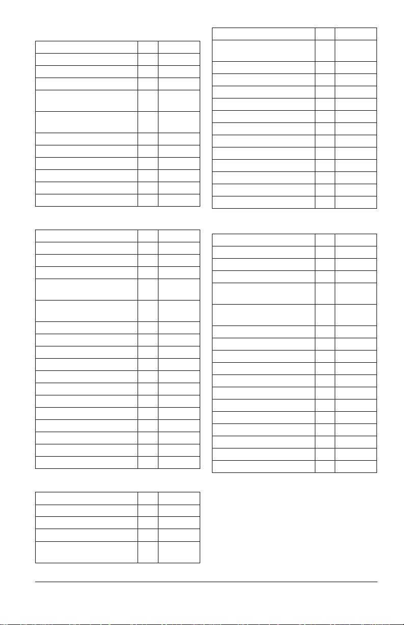
Model 915236
Description Qty. Part No.
Drive Belt 1 07200718
Mower Belt 1 07200023
Mower Blade 1 04771200
Front Wheel and Tire
1 07101127
Assembly
Drive Wheel and Tire
1 07101130
Assembly
Armrest Kit – Left 1 51528800
Armrest Kit – Right 1 51528900
Spark Plug 1 21536100
Fuel Filter 1 21548101
Oil Filter 1 21548100
Air Filter 1 21548000
Description Qty. P art No.
Drive Wheel and Tire
1 07101213
Assembly
Armrest Pad – Left 1 21559500
Armrest Pad – Right 1 21559700
Armrest Kit – Left 1 51530000
Armrest Kit – Right 1 51530100
Seatback Cushion 1 21560600
Seat Bottom Cushion 1 21560800
Hydraulic Oil Filter 2 21545100
Hydraulic Oil (32 oz) AR 00057100
Spark Plug 1 21536100
Fuel Filter 1 21548101
Oil Filter 1 21548100
Air Filter 1 21548000
Model 915238
Description Qty. Part No.
Drive Belt 1 07200724
Mower Belt 1 07200523
Mower Blade 1 04769800
Front Wheel and Tire
1 07101105
Assembly
Drive Wheel and Tire
1 07101213
Assembly
Armrest Pad – Left 1 21559500
Armrest Pad – Right 1 21559700
Armrest Kit – Left 1 51530000
Armrest Kit – Right 1 51530100
Seatback Cushion 1 21560600
Seat Bottom Cushion 1 21560800
Hydraulic Oil Filter 2 21545100
Hydraulic Oil (32 oz) AR 00057100
Spark Plug 1 21536100
Fuel Filter 1 21548101
Oil Filter 1 21548100
Air Filter 1 21548000
Model 915240
Description Qty. Part No.
Drive Belt 1 07200724
Mower Belt 1 07200023
Mower Blade 1 04771200
Front Wheel and Tire
1 07101105
Assembly
Model 915242
Description Qty. P art No.
Drive Belt 1 07200724
Mower Belt 1 07200804
Mower Blade 1 04965000
Front Wheel and Tire
1 07101105
Assembly
Drive Wheel and Tire
1 07101213
Assembly
Armrest Pad – Left 1 21559500
Armrest Pad – Right 1 21559700
Armrest Kit – Left 1 51530000
Armrest Kit – Right 1 51530100
Seatback Cushion 1 21560600
Seat Bottom Cushion 1 21560800
Hydraulic Oil Filter 2 21545100
Hydraulic Oil (32 oz) AR 00057100
Spark Plug 1 21536100
Fuel Filter 1 21548101
Oil Filter 1 21548100
Air Filter 1 21548000
EN - 19
Page 22
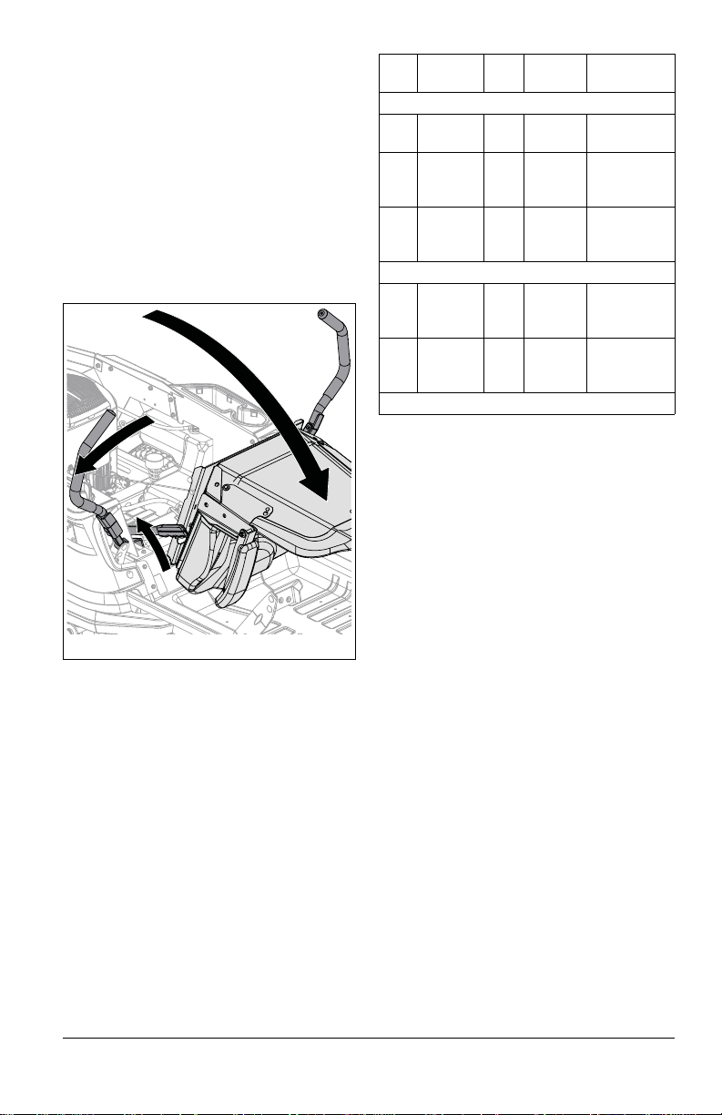
SERVICE POSITION
Figure 12
See Figure 12.
Before starting any of the following
maintenance procedures:
1. Park unit a flat, level surface.
2. Stop engine, remove key and wait for all
moving parts to stop and for hot parts to
cool.
3. Move steering levers to neutral position
and rotate handles outward.
4. Engage parking brake.
5. Disconnect spark plug wires from engine.
6. Tip seat forward.
Test Steering
Levers
1 Neutral Off On Engine
2Forward,
Neutral,
Reverse
3Forward,
Neutral,
Reverse
Operating Interlock (Engine On)
4 * Forward,
Neutral,
Reverse
5 * Forward,
Neutral,
Reverse
* When operator lifts off seat.
PTO Parking
Brake
Starting Interloc k
On On or
Off
On
Off Engine does
or
Off
On On or
Off
On
Off Engine
or
Off
Result
starts.
Engine does
not start.
not start.
Engine
shuts off.
shuts off.
CHECK PARKING BRAKE
1. Place unit in service position. See
Service Position on page 20.
2. Set both transaxle bypass levers in the
rear position. See Move Unit Manually on
page 15.
3. Push unit forward.
• If unit does not move f orward, no further
action is needed.
• If unit easily moves forward, adjust the
brake lever. See Adjust Parking Brake
Lever on page 30.
IMPORTANT: Reconnect spark plug wires
after maintenance.
CHECK SAFETY INTERLOCK SYSTEM
Check function of the Safety Interlock System
by performing the tests below. Contact your
Gravely dealer for repair if any of the tests
fail.
CHECK ENGINE OIL
NOTICE: Engine oil level must be maintained
at correct level or engine damage may occur.
Refer to engine manual.
EN - 20
Page 23
CHECK TIRE PRESSURE
Figure 13
1
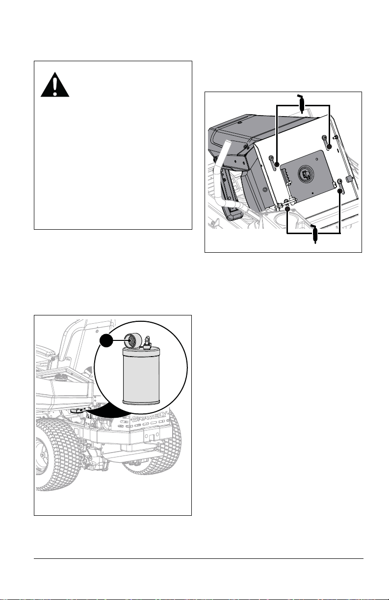
1. Carbon Canister Filter
Figure 14
See Specifications on page 37 for
recommended tire pressure.
WARNING: AVOID INJURY.
Explosive separation of tire
and rim parts is possible.
• DO NOT inflate tires above
the recommended pressure.
• DO NOT inflate tires with a
compressor; use a hand
pump.
• DO NOT stand in front of
tire assembly when
inflating. Use a clip-on
chuck and extension hose
long enough to allow you to
stand to one side.
• DO NOT mount a tire
without proper equipment
and experience.
CHECK CARBON CANISTER FILTER
Models 915176, 915236, 915238, 915240,
915242
See Figure 13.
Clean or replace filter whenever engine air
filter is cleaned or replaced.
LUBRICATE UNIT
See Figure 14.
1. Place unit in service position. See
Service Position on page 20.
2. Apply grease to seat tracks through slots
under seat plate.
3. Return seat to operating position and
slide seat back and forth to spread
grease along tracks.
CHECK FASTENERS
Check for loose or missing hardware.
EN - 21
Page 24
CHECK MOWER BLADES
Figure 15
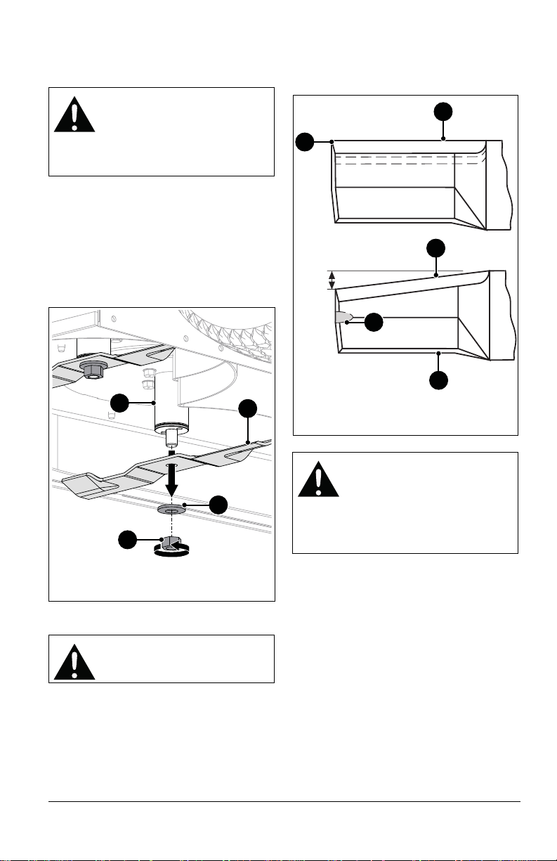
1. Spindle
2. Mower Blade
3. Washer
4. Nut
1
2
4
3
Figure 16
1. Cutting Edge
2. Square Corner
3. Air Lift Erosion
4. Air Lift
1
2
3
4
DO NOT sharpen to this
pattern.
Sharpen to this pattern.
1
Check blades for wear. Replace or sharpen
as needed.
CAUTION: AVOI D INJURY. Use
sturdy gloves or padding to
protect hands when working with
mower blades.
Rotation of one blade rotates the
other blades.
Remove Blades
See Figure 15.
1. Stop engine, remove key and wait for all
moving parts to stop and for hot parts to
cool.
2. Remove hardware securing blades to
spindles and remove blades. Retain all
hardware for reinstallation.
2. File or grind an equal amount of material
from each cutting edge of the blade until
sharp. DO NOT change angle of cutting
edge or round the corner of the blade.
Sharpen Blades
CAUTION: DO NOT sharpen
See Figure 16.
1. Remove blades from unit. Discard blades
blades while attached to unit.
if:
• More than 1.3 cm (1/2") of metal is
removed.
• Air lifts are eroded.
• Blades are bent or broken.
CAUTION: Unbalanced blades
cause excessive vibration and
eventual damage to unit.
Balance blades before
reinstalling on unit.
3. Check blade balance by sliding blade on
NEVER weld or straighten
blades.
an unthreaded bolt. If blade does not
remain horizontal, sharpen the heavy end
until blade is balanced.
Install Blades
1. Reinstall blades, washers and nuts on
EN - 22
spindles. See Figure 15.
2. Torque bolts to 136 – 163 N•m
(100 – 120 lb-ft).
Page 25
CHECK BATTERY
Figure 17
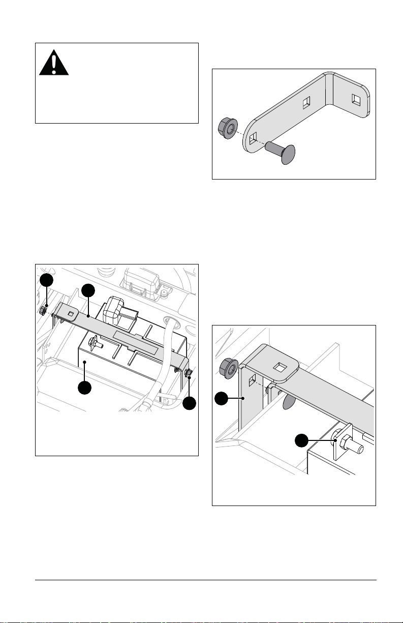
1. Battery
2. Battery Bracket
3. Flange Nut
1
2
3
3
Figure 18
Figure 19
1. Negative Battery Terminal
2. L-Bracket
1
2
WARNING: Battery posts,
terminals and related
accessories contain lead and
lead compounds, chemicals
known to the State of California
to cause cancer and
reproductive harm. Wash hands
after handling.
Remove Battery
1. Place unit in service position. See
Service Position on page 20.
2. Disconnect the negative cable and then
the positive cable from the battery.
See Figure 17.
3. Remove hardware retaining battery
brackets and remove brackets.
IMPORTANT: Remove flange nuts and
brackets only. DO NOT remove bolts from
battery tray.
4. Remove battery.
1. Remove hardware retaining L-bracket to
battery bracket and reinstall hardware
into L-bracket hole nearest curved edge.
See Figure 18.
See Figure 19.
2. Place battery on battery tray so terminals
are positioned nearest right side of unit.
3. Install battery bracket over battery and
onto bolts in battery tray.
4. Reinstall L-bracket onto bolt and secure
with flange nut.
5. Secure remaining battery bracket end to
battery tray with original flange nut.
6. Connect positive cable to positive battery
terminal and then the negative cable to
negative battery terminal.
7. Return seat to operating position.
Install Battery
Install Factory Battery
Battery bracket configurations for a U1
battery and a factory-installed battery are
different. If replacing a U1 battery with a
factory-installed battery, see step 1. If a
factory-installed battery was most recently
used, advance to step 2.
Install U1 Battery
1. Remove factory battery. See Remove
Battery on page 23.
2. Remove hardware from L-bracket and
secure L-bracket to battery bracket . See
EN - 23
Figure 20.
Page 26
3. Place U1 battery in battery tray so
Figure 20
Figure 21
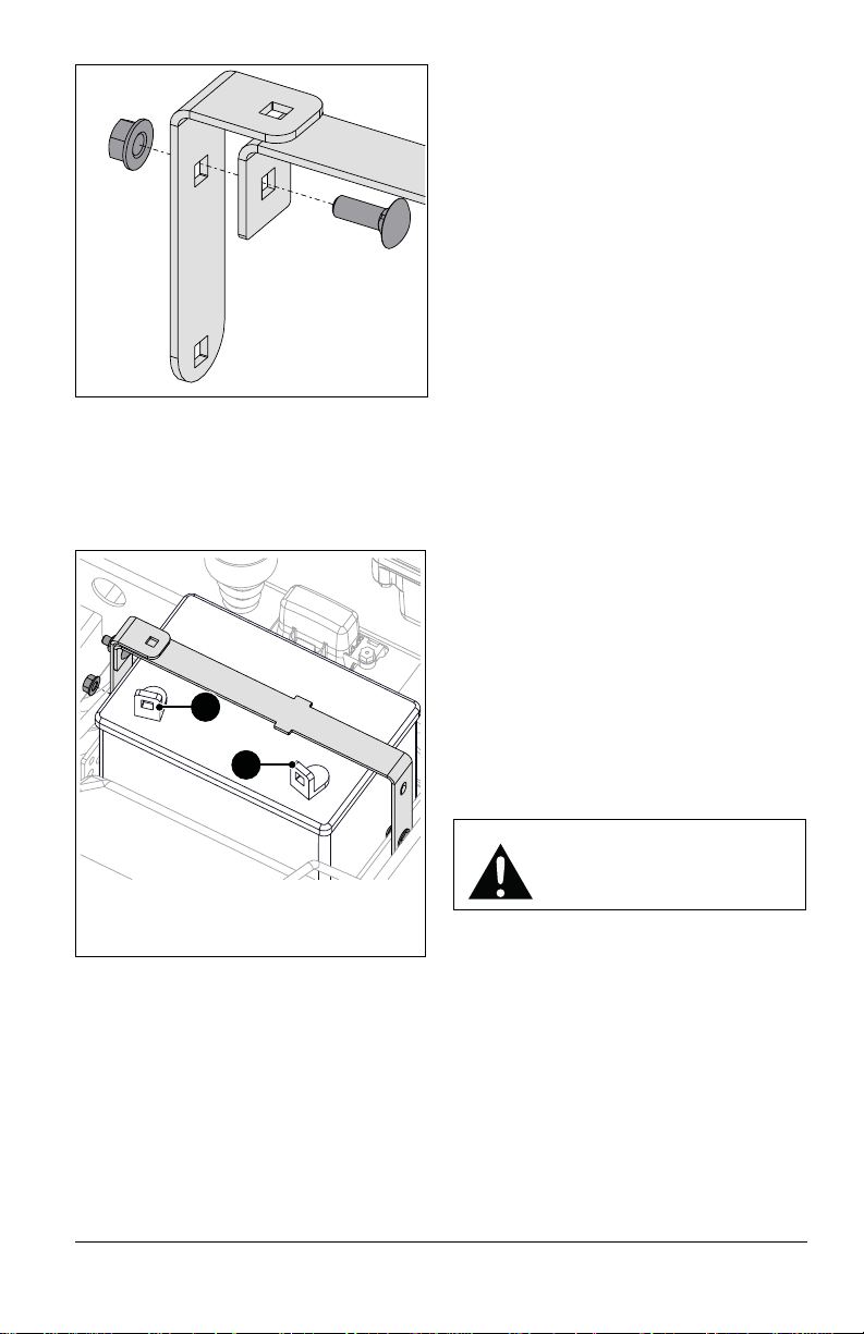
1. Positive Battery Terminal
2. Negative Battery Terminal
1
2
terminals are positioned toward the front
of unit.
4. Install battery bracket over battery and
onto bolts in battery tray. Secure with two
flange nuts. See Figure 21.
4. Reinstall battery. See Install Battery on
page 23.
Charge Battery
Check battery with a voltmeter. If battery is
less than 11 volts, charge battery.
NOTICE: DO NOT fast charge. Charging at a
higher rate damages or destroys the battery.
ONLY use an automatic charger designed for
use with your battery.
IMPORTANT: Always follow information
provided on battery by battery manufacturer.
Contact battery manufacturer for detailed
information about charging.
IMPORTANT: Gravely does not recommend
jump starting your unit. Jump-starting can
damage engine and system components.
Refer to engine manual for detailed
information.
1. Remove battery from unit. See Remo ve
Battery on page 23.
2. Place battery on bench or other wellventilated area.
3. Connect positive lead of charger to
positive battery terminal.
4. Connect negative lead of charger to
negative battery terminal.
5. Charge battery following battery
manufacturer’s instructions.
6. Reinstall battery. See Install Battery on
page 23.
5. Connect positive cable to positive battery
terminal and then the negative cable to
negative battery terminal.
6. Return seat to operating position.
Clean Battery
1. Remove battery from unit. See Remove
Battery on page 23.
2. Clean terminals and battery cable ends
3. Coat terminals with dielectric grease or
with a wire brush.
petroleum jelly.
CHECK MOWER BELTS
Check belts for wear and replace as needed.
Remove Deck Drive Belt
CAUTION: Keep body parts
away from idler when
releasing idler spring tension.
1. Stop engine, remove key and wait for all
moving parts to stop and for hot parts to
cool.
2. Lower deck to lowest cutting height.
See Figure 22.
3. Remove self-tapping screws from each
belt cover and remove belt covers. Retain
all parts for reinstallation.
4. Disconnect idler spring from spring
bracket to release belt tension.
EN - 24
Page 27
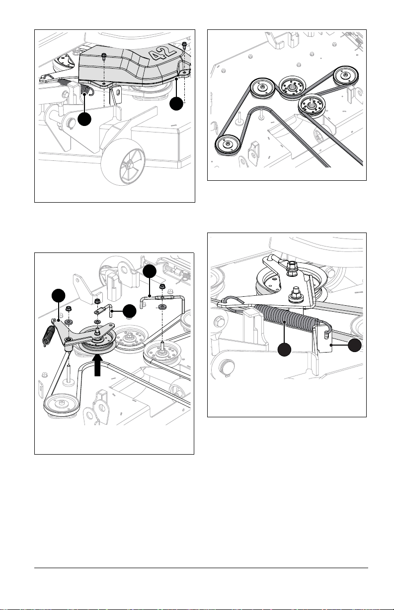
5. Remove hardware retaining idler arm and
Figure 22
1. Spring
2. Belt Cover
1
2
Figure 23
1. Idler Arm
2. Belt Finger
1
2
2
Figure 24
Figure 25
1. Idler Spring
2. Spring Bracket
1
2
two belt fingers from mower deck and
remove idler arm and belt fingers. Retain
all parts for reinstallation. See Figure 23.
2. Reinstall idler arm and belt fingers. See
Figure 23.
3. Secure idler spring to spring bracket so
drive belt has tension. See Figure 25.
6. Remove deck drive belt.
Install Deck Drive Belt
1. Install deck drive belt. See Figure 24.
IMPORTANT: Belt will not have tension until
routed around drive pulley and idler arm is
reinstalled.
4. Reinstall belt covers and secure each
with self-tapping screws removed earlier.
IMPORTANT: Make sure belt has tension and
remains aligned after installation is complete.
Remove Ground Drive Belt
IMPORTANT: Retain all parts for
reinstallation.
1. Place unit in service position. See
Service Position on page 20.
2. Remove deck drive belt. See Remove
Deck Drive Belt on page 24.
3. Loosen nut on eye bolt and disconnect
idler arm spring. See Figure 26.
EN - 25
Page 28
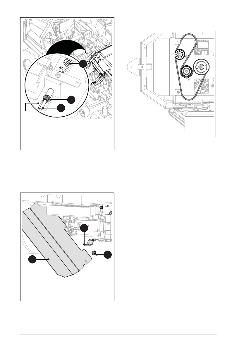
See Figure 27.
Figure 26
1. Nut
2. Eye Bolt
3. Idler Arm Spring
1
2
3
6.1 cm
(2.4")
Figure 27
1. Heat Shield
2. Clutch Stop Bracket
3. Self-tapping Screw
1
2
3
Figure 28
Rear
4. Remove the right-side self-tapping screw
from heat shield and rotate shield out of
the way.
5. Remove two self-tapping screws from
clutch stop bracket and remove bracket.
Install Ground Drive Belt
1. Install ground drive belt. See Figure 28.
2. Reconnect clutch wire.
3. Reinstall clutch stop bracket and secure
with two self-tapping screws removed
earlier.
4. Rotate heat shield into position and
secure to unit with self-tapping screw
removed earlier.
5. Reconnect idler arm spring to eye bolt
and secure bolt to unit with nut. Tighten
until the nut is 6.1 cm (2.4") from the
threaded end of the eye bolt. See
Figure 26.
6. Reinstall deck drive belt. See Install Deck
Drive Belt on page 25.
6. Disconnect clutch wire.
7. Remove ground drive belt.
NOTICE: Route the belt over the top of the
pulleys for easiest removal.
EN - 26
Page 29
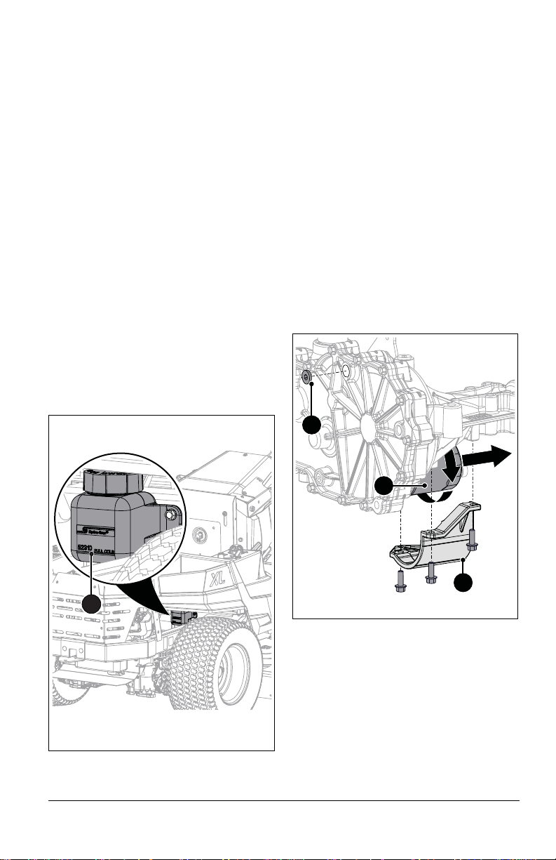
HYDRAULIC OIL
Figure 29
The hydraulic fluid should be at the cold fill
line of the expansion tank.
1. Cold Fill Indicator Mark
1
Figure 30
1. Vent Plug
2. Oil Filter
3. Filter Guard
1
3
2
Models 915200, 915202, 915204, 915206,
915216, 915218, 915238, 915240, 915242
Check Hydraulic Oil Level
See Figure 29.
1. Place unit in service position. See
Service Position on page 20.
2. Check oil level in expansion tanks. Oil
should reach the cold fill indicator mark.
NOTICE: Engine should be cold when
checking initial oil level.
3. Operate unit for about 1 minute and
recheck the levels.
4. Add hydraulic oil, if needed. See Add
Hydraulic Oil on page 27.
Add Hydraulic Oil
See Figure 29.
1. Place unit in service position. See
Service Position on page 20.
2. Remove the cap from the expansion tank.
3. Fill the expansion tank with 15W-50
synthetic motor oil (Gravely p/n
00057100) or equivalent until oil level
reaches the cold fill line on the tank.
4. Reinstall the expansion tank cap.
Change Hydraulic Oil and Filter
Models 915200, 915202, 915204, 915206,
915216, 915218, 915238, 915240, 915242
NOTICE: Change hydraulic fluid and filter
after the first 75 hours of operation and then
every 400 hours. Use 15W-50 synthetic
motor oil (Gravely p/n 00057100) or
equivalent.
1. Operate unit for a few minutes to warm
hydraulic oil.
2. Stop engine, remove key and wait for all
moving parts to stop and for hot parts to
cool.
3. Position container under oil filter to catch
used oil.
See Figure 30.
4. Remove filter guard and oil filter from
transaxle.
5. Remove the vent plug from the inlet port
and allow the transaxle to drain
completely.
6. Wipe filter-mounting surface clean.
7. Lubricate rubber gasket on new oil filter
with clean hydraulic oil.
8. Spin filter onto filter housing until it makes
contact, and then turn filter 3/4 turn to
tighten.
9. Reinstall filter guard and torque to 7.3
N•m (65 lb-in). DO NOT overtighten.
10. Add 15W-50 synthetic motor oil (Gravely
p/n 00057100) or equivalent until oil
appears at the bottom of the vent port
(1892.7 mL (64 fl. ounces) per t ransaxle).
EN - 27
Page 30
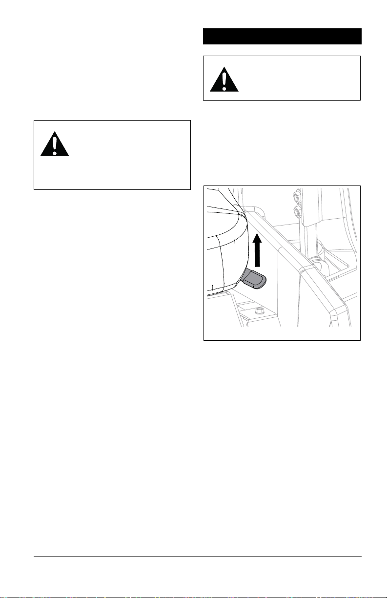
11. Reinstall the vent plug and tighten to 20.3
Figure 31
N•m (180 lb-in).
12. Add hydraulic oil to expansion tank until
oil reaches cold fill indicator mark. See
Add Hydraulic Oil on page 27.
13. Repeat steps 3 – 12 for other transaxle.
14. Purge hydraulic system . See Purge
Hydraulic System on page 28.
Purge Hydraulic System
WARNING: This adjustment
requires operating the engine.
Use extreme care to avoid
contact with moving parts and
hot surfaces. Be sure rear of
unit is well supported and
secure before starting engine.
1. With the unit up to and facing a wall, jack
up the unit so that both drive wheels are
off the ground.
2. Disengage the parking brake and put the
transaxle bypass levers in the neutral
position (see Move Unit Manually on
page 15).
3. Start the engine and slowly move the
steering levers in forward and reverse five
or six times.
4. Stop the engine and put the transaxle
bypass levers in the drive position (see
Move Unit Manually on page 15).
5. Start the engine and slowly move the
steering levers in forward and reverse five
or six times.
6. Stop the engine, check the oil level and
add oil as needed.
7. Repeat steps 2 – 6 until the transaxles
operate smoothly in forward and reverse
at normal speeds without excessive
noise.
ADJUSTMENTS
WARNING: AVOID INJURY.
Read and understand the
Safety section before
proceeding.
ADJUST SEAT
See Figure 31.
1. Pull seat adjustment lever up to unlock
seat.
2. Move seat to desired position.
3. Release seat adjustment lever to lock
seat in place.
ADJUST STEERING LEVERS
Adjust Steering Lever Height
See Figure 32.
1. Remove hardware securing steering
lever to upper control arm.
2. Place steering lever in desired adjusting
hole.
• Use upper and middle holes for highest
lever position.
• Use middle and l ower holes for lowest
lever position.
3. Reinstall hardware in upper control arm.
4. Align levers side to side. See Adjust
Steering Lever Reach on page 29.
5. Fully tighten hardware.
EN - 28
Page 31
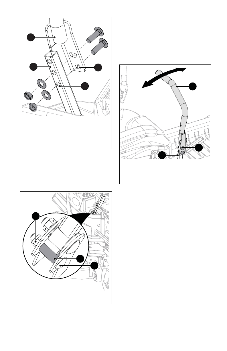
See Figure 33.
Figure 32
1. Adjusting Hole
2. Mounting Hole
3. Steering Lever
4. Upper Control Arm
1
2
3
4
Figure 33
1. Eccentric Spacer
2. Hex Bolt
3. Nut
1
2
3
Figure 34
1. Steering Lever
2. Upper Control Arm
3. Hardware
1
2
3
6. Loosen nut on hex bolt supporting
eccentric spacer.
7. Rotate eccentric spacer around hex bolt
until levers are at the same height.
8. Tighten nut.
3
Adjust Steering Lever Reach
See Figure 34.
1. Loosen hardware securing steering lever
to upper control arm.
2. Pivot steering lever to desired position.
Ensure levers are aligned with each
other.
3. Tighten hardware.
ADJUST UNIT TO TRACK STRAIGHT
NOTICE: Reverse travel can only be
adjusted by your Gravely dealer.
Check Tire Pressure
1. Check pressure of both tires. See
Specifications on page 37 for
recommended tire pressure.
2. Recheck unit tracking. If unit still does not
track straight, note which side the unit
pulls toward and increase the tire
pressure on that side.
IMPORTANT: DO NOT exceed maximum tire
pressure listed on tire sidewall.
If increasing tire pressure on one side does
not correct tracking problem, adjust the
steering levers.
EN - 29
Page 32
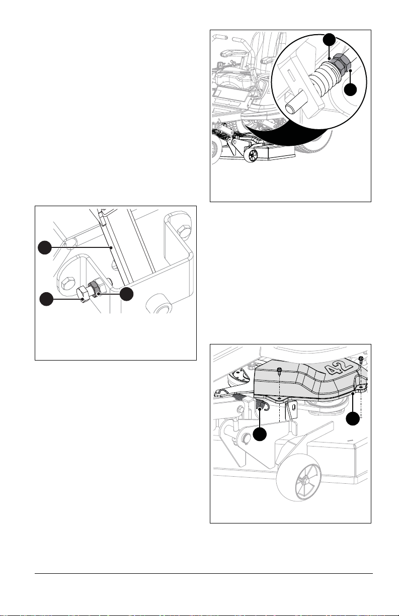
Adjust Steering Levers
Figure 35
1. Steering Control Arm
2. Jam Nut
3. Adjustment Bolt
1
2
3
Figure 36
1
2
1. Upper Jam Nut
2. Lower Jam Nut
Figure 37
1. Spring
2. Belt Cover
1
2
See Figure 35.
If adjusting tire pressure did not correct
tracking problem:
1. Loosen jam nut on adjustment bolt of
steering lever that needs adjustment.
2. Adjust drive wheel speed.
• Turn adjustment bolt counterclockwise
to increase steering lever travel and
drive wheel speed.
• Turn adjustment bolt clockwise to
decrease steering lever travel and drive
wheel speed.
3. Tighten jam nut.
IMPORTANT: Adjustment bolt must contact
steering lever. DO NOT turn adjustment bolt
too far counterclockwise.
REMOVE AND INSTALL MOWER DECK
Remove Deck
1. Set deck to lowest cutting height.
2. Position supports, such as wood blocks,
under mower deck.
See Figure 37.
3. Remove three self-tapping screws from
left belt cover and remove belt cover.
Retain all parts for reinstallation.
4. Disconnect idler spring from spring
bracket to release belt tension.
ADJUST PARKING BRAKE LEVER
1. Park unit a flat, level surface and chock
wheels so unit cannot roll.
2. Position deck at lowest cutting height.
See Figure 36.
3. Loosen upper jam nut and adjust lower
nut up or down until brake lever functions
correctly.
4. Tighten upper jam nut against lower nut.
5. Return seat to operating position.
EN - 30
Page 33
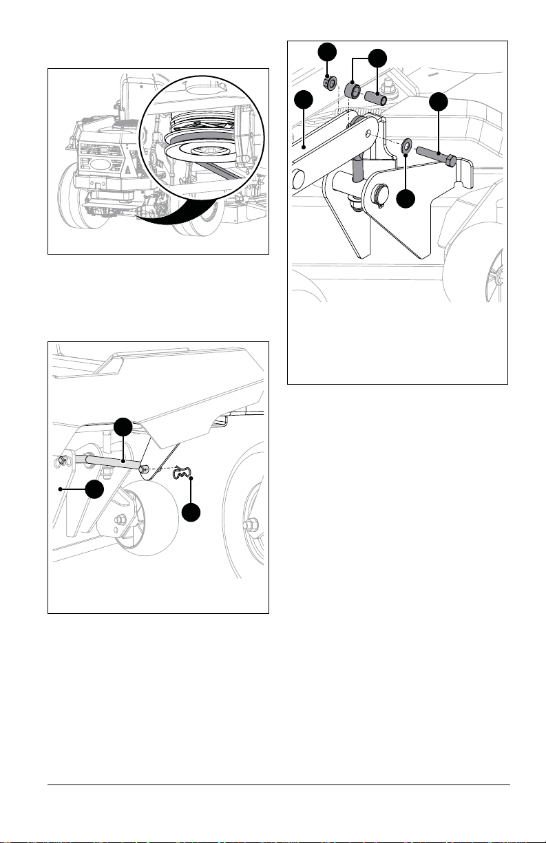
5. Remove deck drive belt from rear drive
Figure 38
Figure 39
1. Mower Deck Bracket
2. Drag Link
3. Hairpin
1
3
2
Figure 40
1. Deck Lift Lever
2. Flange Nut
3. Hex Bolt
4. Flat Steel Washer
5. Sleeve Bushings
1
5
2
3
4
pulley. See Figure 38.
See Figure 39.
6. Remove one hairpin from drag link to
disconnect drag link from mower deck
bracket. Retain all parts for reinstallation.
7. Repeat step 6 on other side.
8. Remove one flange nut, one hex bolt, one
flat steel washer and two sleeve bushings
from deck lift lever. Retain hardware. See
Figure 40.
9. Repeat step 8 for the three remaining
deck lift levers.
10. Move deck from under unit.
Install Deck
1. Position deck under unit.
See Figure 41.
2. Align holes in deck lift lever with slot in
deck link.
3. Position one 1/2 x 3/4 x 3/64" (shorter)
sleeve bushing between deck link and
interior bracket of deck lift lever.
4. Insert 3/8 x 1/2 x 1" (longer) sleeve
bushing through slot in deck link and
shorter sleeve bushing.
5. Insert hex bolt through washer, deck lift
lever, deck link and sleeve bushings.
Secure with flange nut.
EN - 31
Page 34
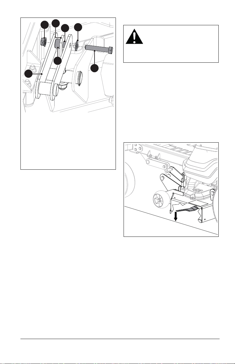
6. Repeat steps 2 – 5 for the three
Figure 41
1. Deck Lift Lever
2. Deck Link
3. 3/8 x 1/2 x 1" (Longer) Sleeve Bushing
4. 1/2 x 3/4 x 3/64" (Shorter) Sleeve
Bushing
5. Hex Bolt
6. Flat Steel Washer
7. Flange Nut
2
7
5
3
4
6
1
Figure 42
remaining deck lift levers.
7. Reinstall drag link through mower deck
bracket and secure with hairpin removed
earlier. See Figure 39.
8. Repeat step 7 on other side.
9. Secure drive belt around drive pulley.
10. Secure idler spring to spring bracket so
drive belt has tension.
11. Reinstall belt cover and secure with three
self-tapping screws removed earlier. See
Figure 37.
ADJUST MOWER DECK
CAUTION: AVOID INJURY. Use
sturdy gloves or padding to
protect hands when working with
mower blades.
Rotation of one blade rotates the
other blades.
Level Mower Deck
IMPORTANT: Make sure unit is on a flat,
level surface and that tires are inflated to the
recommended pressures. See Specifications
on page 37
1. Set deck to highest cutting height.
2. Position mower blades so blade ends
point left to right across the width of the
deck.
3. On both sides of the unit, measure the
distance to the ground at the cutting edge
of the blade. See Figure 42.
• If the measurements are ± 0.635 cm
(1/4") of one another, no adjustment is
needed.
• If adjustments are needed, adjust the
nylon locking flange nut on the deck
link. Tighten the nut to raise the deck;
loosen the nut to lower the deck. See
Figure 43.
IMPORTANT: It may be necessary to adjust
the nut on more than one of the deck links.
EN - 32
Page 35

Set Blade Pitch
Figure 43
1. Deck Link
2. Nylon Locking Flange Nut
1
2
Figure 44
Pitch is the difference in blade height from
front to back.
IMPORTANT: Level the mower deck before
setting blade pitch.
1. Set deck to highest cutting height.
2. Position mower blades so blade ends
point front to back.
3. On both sides of the unit, measure the
distance to the ground at the front and
rear tip of the blade. See Figure 44.
• If the front tip of the blade is ± 0.635 cm
(1/4") lower than the rear, no
adjustment is needed.
• If adjustments are needed, adjust the
nylon locking flange nut on the deck
link. Tighten the nut to raise the deck;
loosen the nut to lower the deck. See
Figure 43.
EN - 33
Page 36
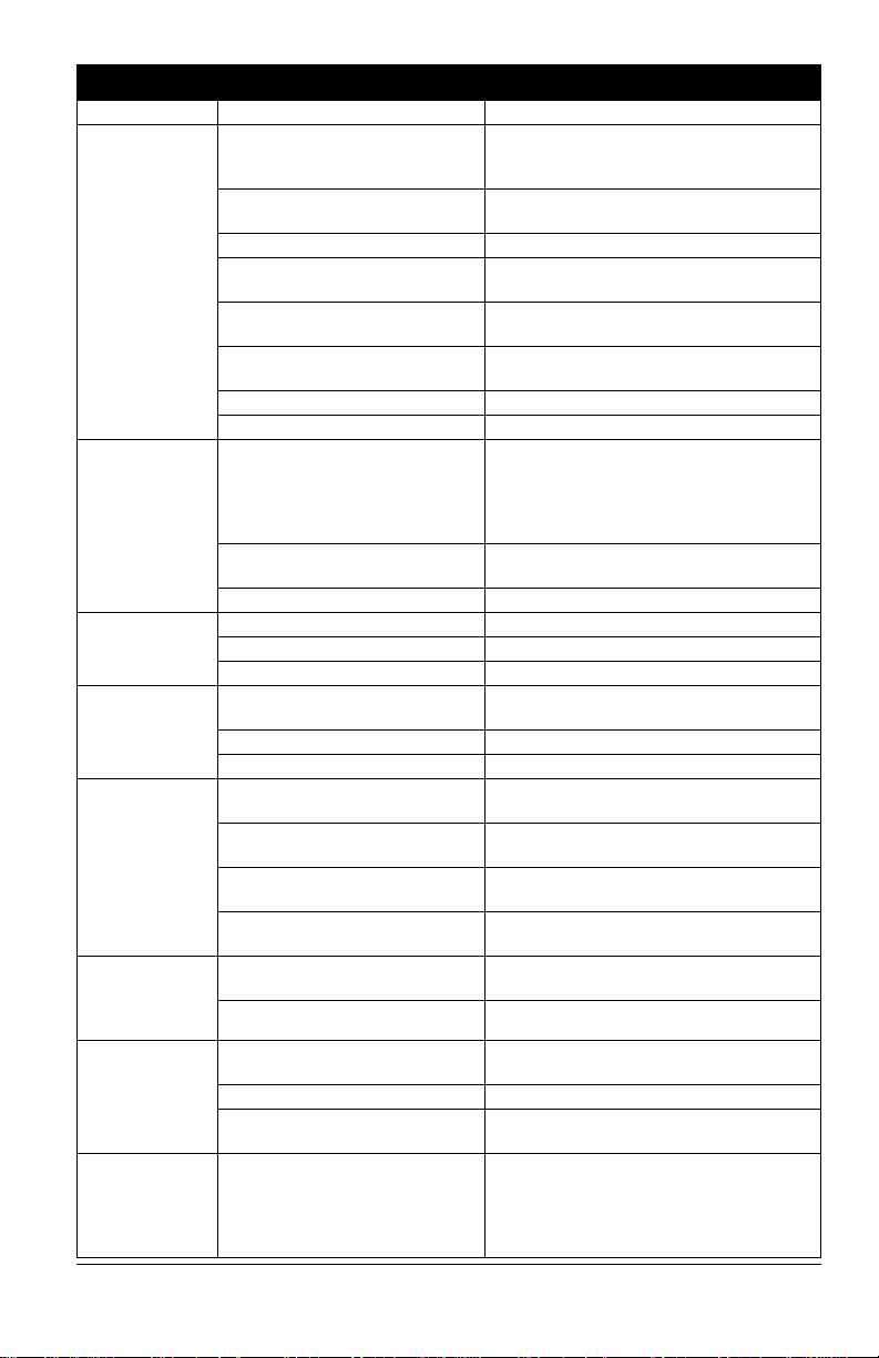
TROUBLESHOOTING
Problem Probable Cause Correction
Engine does
not start.
Engine runs
rough.
Engine
overheats.
Unit does not
drive.
PTO
malfunctions.
Unit moves
with engine off
and parking
brake engaged.
Unit does not
track straight.
Unit creeps
when steering
levers are in
neutral
position.
Safety Interlock System is not
engaged or is faulty.
Fuel tank is empty. Fill fuel tank. See Before Operating Unit
Fuel supply is contaminated. Replace with clean fuel.
Battery is discharged. Charge battery. See Charge Battery on
Connection between battery and
battery cables is poor.
Spark plug wire(s) are loose or
spark plug(s) are faulty.
Electrical system is faulty. Contact your Gravely dealer.
Engine is faulty. Contact your Gravely dealer.
Choke control knob is in on
position. (Models 915204,
915206, 915218, 915230,
915236, 915238, 915240,
915242)
Air filter cartridge is plugged. Clean or replace air filter cart ridge. Refer
Engine is faulty. Contact your Gravely dealer.
Engine oil level is low. Add engine oil. Refer to engine manual.
Cooling fins are plugged. Clean engine. Refer to engine manual.
Engine is faulty. Contact your Gravely dealer.
The transaxles are bypassed. Engage levers. See Move Unit Manually
Ground drive belt is faulty. Contact your Gravely dealer.
Transaxles are faulty. Contact your Gravely dealer.
Operator presence switch is not
engaged.
Operator presence switch is
faulty.
Deck drive belt is faulty. Replace deck drive belt. See Remove
PTO switch, wiring, connectors
or clutch are faulty.
Parking brake needs adjustment. Adjust parking brake lever. See Adjust
Parking brake is faulty. Contact your Gravely dealer.
Tire pressure is incorrect. Check tire pressure. See Specifications
Steering levers need adjustment. See Adjust Steering Levers on page 28.
Transaxles and/or linkages need
adjustment.
Transmission and/or linkage
need adjustment.
Check Safety Interlock System. See
Check Safety Interlock System on
page 20.
on page 13.
page 24.
Tighten and/or clean battery and battery
cables. See Clean Battery on page 24.
Connect spark plug wire(s) or replace
spark plug(s). Refer to engine manual.
Move knob to off position.
to engine manual.
on page 15.
Activate switch by sitting on operator seat.
Contact your Gravely dealer.
Deck Drive Belt on page 24.
Contact your Gravely dealer.
Parking Brake Lever on page 30.
on page 37.
Contact your Gravely dealer.
Contact your Gravely dealer.
EN - 34
Page 37

TROUBLESHOOTING
Problem Probable Cause Correction
Poor cutting
quality.
Mower blades not level or mower
deck pitch is incorrect.
Mower blades are dull or faulty. Sharpen or replace mower blades. See
Mowing speed is too fast. Drive slower when cutting grass.
Belt tension or condition is poor. Replace deck drive belt. See Check
Cutting height is too low. Do not set height of cut too low. For very
Level and adjust pitch of mower deck.
See Adjust Mower Deck on page 32.
Sharpen Blades on page 22.
Mower Belts on page 24.
tall grass, mow twice.
EN - 35
Page 38

STORAGE ACCESSORIES
SHORT-TERM STORAGE
IMPORTANT: NEVER wash unit with high-
pressure water or store outdoors.
1. Allow unit to cool and clean with mild
soap and water.
2. Tighten all hardware to correct
specifications.
3. Inspect unit for visible signs of wear or
damage. Repair as needed.
4. Prepare fuel system for storage.
NOTICE: Gravely recommends using a
quality fuel stabilizer in all fuel. Gasoline left
in the fuel system without a stabilizer, even
for short periods of time, deteriorates and
leaves gummy deposits in the system that
may damage the carburetor and fuel hoses,
filter and tank. For the best effectiveness, add
stabilizer to all fuel containers whenever
purchasing fuel. Add the stabilizer to the
container before adding fuel.
a. Add fuel stabilizer (see Service Parts
on page 16) or equivalent according
to manufacturer's instructions to the
fuel tank and any fuel containers with
remaining fuel.
b. Run engine outdoors for at least
5 minutes to allow stabilizer to reach
the carburetor.
5. Turn ignition key to off position and
remove from ignition.
6. Store unit in a cool, dry, protected area.
DO NOT store unit outdoors.
See your Gravely dealer for a complete list of
compatible accessories and attachments for
your unit.
Description Part No.
Mulch Kit – 42" 71513900
Mulch Kit – 52" 71514000
Mulch Kit – 60" 71514400
Headlight Kit 71514100
Bagger Kit – 42" & 52" 81504300
Bagger Kit – 60"
Kit for 60" Decks
81504300
71514500
LONG-TERM STORAGE
1. Perform short-term storage procedures.
2. Lubricate as directed in Maintenance on
page 16.
3. Touch-up all scratched painted surfaces.
4. Remove and charge battery as directed
in Charge Battery on page 24. Store
battery in a cool, dry, protected area.
5. Store unit in a cool, dry, protected area.
Do not store unit outdoors.
START-OF-SEASON PREPARATION
1. Before adding fuel for the first time after
long-term storage, add fresh, stabilizertreated fuel to fuel tank and any fuel
containers with remaining fuel.
2. Charge and install the battery.
EN - 36
Page 39
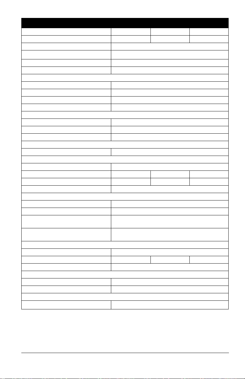
SPECIFICATIONS
Model Number 915172 915174 915176
Model ZT X 42 ZT X 52 ZT X 42 CARB
Engine Kohler 7000 Pro Twin with Smart Choke
3
Engine Displacement – cm
Maximum RPM – No Load 3300
Oil Capacity Refer to Engine Manual
Drive
Forward Maximum – km/h (mph) 11.3 (7.0)
Reverse Maximum – km/h (mph) 4.8 (3.0)
Turning Radius Zero
Brakes Internal Transmission
Electrical
Starter Electric
Battery 12V Maintenance-Free 190CCA (U1 Replaceable)
PTO (Power Take-Off) Electric
Fuel
Fuel Tank Capacity – Liter (gal) 10.5 (2.8)
Size and Weight
Length – cm (in) 196.9 (77.5)
Width – cm (in) 137.7 (54.2) 161.0 (63.4) 137.7 (54.2)
Weight – kg (lbs.) 258.5 (570.0) 279.0 (615.0) 258.5 (570.0)
Height – cm (in) 103.9 (40.9)
Tires
Front Tire Size – in 11 x 4-5
Rear Tire Size – in 18 x 8.5-8
Recommended Front Tire
Pressure – kPa (psi)
Recommended Rear Tire
Pressure – kPa (psi)
Mower Deck
Cutting Height – cm (in) 3.8 – 11.4 (1.5 – 4.5)
Cutting Width – cm (in) 106.7 (42.0) 132.1 (52.0) 106.7 (42.0)
Mower Deck Lift Foot Operated
Towing
Max. Towing Capacity – kg (lbs) 136.0 (300.0)
Max. Tongue Weight – kg (lbs) 13.6 (30.0)
Transmission
Type
(in3)
Maintenance-Free Hydro-Gear
725.0 (44.2)
317.2 (46.0)
68.5 (10.0)
®
EZT Transaxles
EN - 37
Page 40
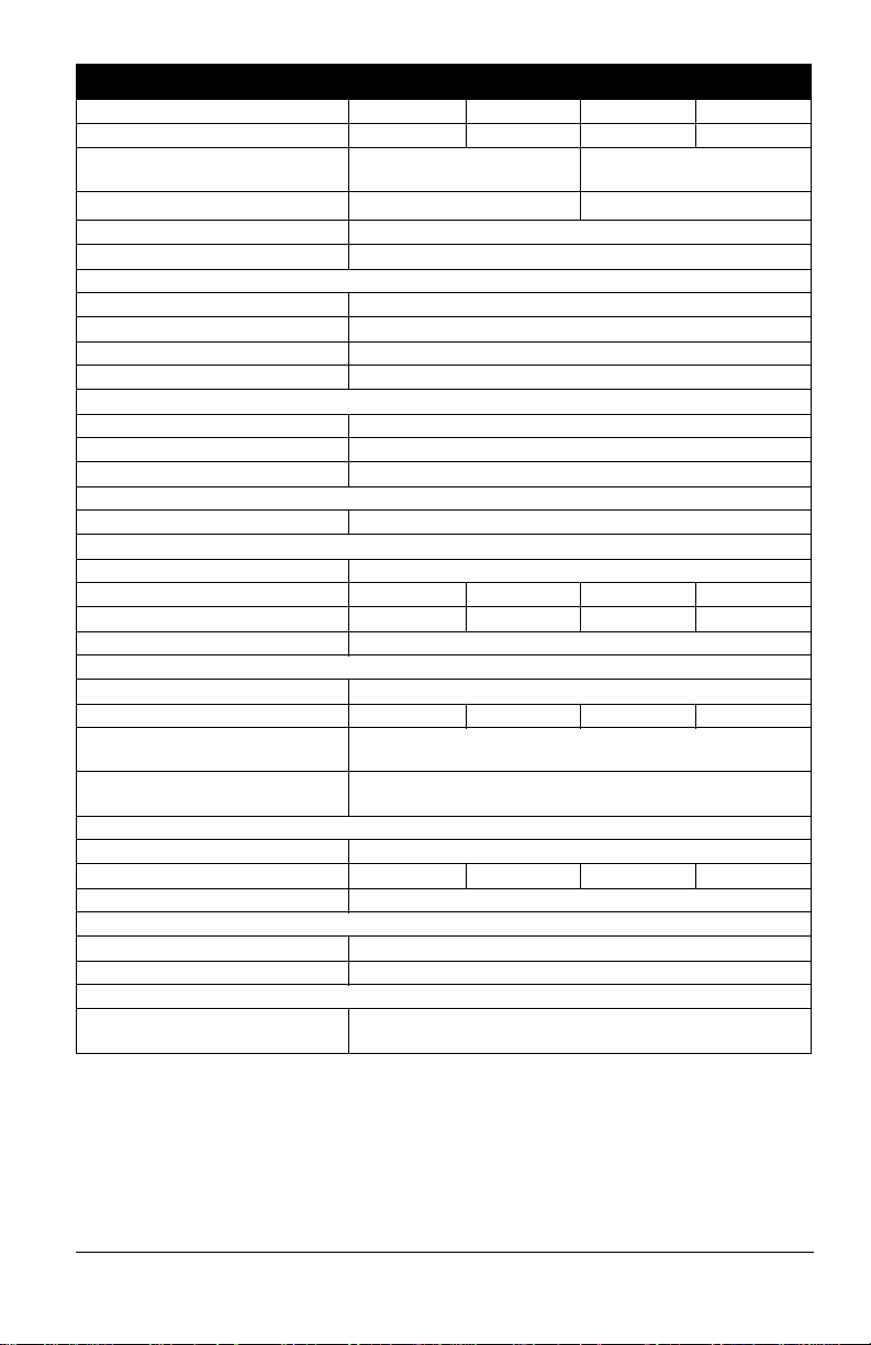
SPECIFICATIONS
Model Number 915200 915202 915204 915206
Model ZT XL 52 ZT XL 42 ZT XL 52 ZT XL 42
Engine Kohler 7000 Pro with Smart
3
Engine Displacement – cm
Maximum RPM – No Load 3300
Oil Capacity Refer to Engine Manual
Drive
Forward Maximum – km/h (mph) 11.3 (7.0)
Reverse Maximum – km/h (mph) 4.8 (3.0)
Turning Radius Zero
Brakes Internal Transmission
Electrical
Starter Electric
Battery 12V Maintenance-Free 190CCA (U1 Replaceable)
PTO (Power Take-Off) Electric
Fuel
Fuel Tank Capacity – Liter (gal) 10.5 (2.8)
Size and Weight
Length – cm (in) 196.9 (77.5)
Width – cm (in) 161.0 (63.4) 137.7 (54.2) 161.0 (63.4) 137.7 (54.2)
Weight – kg (lbs.) 308.0 (679.0) 299.8 (661.0) 308.9 (681.0) 300.7 (663.0)
Height – cm (in) 103.9 (40.9)
Tires
Front Tire Size – in 11 x 6-5
Rear Tire Size – in 20 x 10-10 20 x 8-10 20 x 10-10 20 x 8-10
Recommended Front Tire
Pressure – kPa (psi)
Recommended Rear Tire
Pressure – kPa (psi)
Mower Deck
Cutting Height – cm (in) 3.8 – 11.4 (1.5 – 4.5)
Cutting Width – cm (in) 132.1 (52.0) 106.7 (42.0) 132.1 (52.0) 106.7 (42.0)
Mower Deck Lift Foot Operated
Towing
Max. Towing Capacity – kg (lbs) 136.0 (300.0)
Max. Tongue Weight – kg (lbs) 13.6 (30.0)
Transmission
Type Hydro-Gear® ZT2800 with charge pumps and external
(in3)
Choke
725.0 (44.2) 726.0 (44.3)
206.8 (30.0)
68.5 (10.0)
filter
Kawasaki FR
EN - 38
Page 41
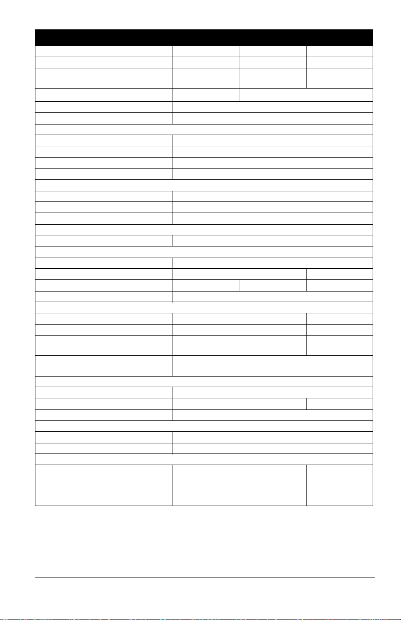
SPECIFICATIONS
Model Number 915216 915218 915230
Model ZT XL 60 ZT XL 60 ZT X 52
Engine Kohler 7000 Pro
3
Engine Displacement – cm
Maximum RPM – No Load 3300
Oil Capacity Refer to Engine Manual
Drive
Forward Maximum – km/h (mph) 11.3 (7.0)
Reverse Maximum – km/h (mph) 4.8 (3.0)
Turning Radius Zero
Brakes Internal Transmission
Electrical
Starter Electric
Battery 12V Maintenance-Free 190CCA (U1 Replaceable)
PTO (Power Take-Off) Electric
Fuel
Fuel Tank Capacity – Liter (gal) 10.5 (2.8)
Size and Weight
Length – cm (in) 196.9 (77.5)
Width – cm (in) 181.6 (71.5) 161.0 (63.4)
Weight – kg (lbs.) 314.8 (694) 316.2 (697) 274.4 (605.0)
Height – cm (in) 103.9 (40.9)
Tires
Front Tire Size – in 11 x 6-5 11 x 4-5
Rear Tire Size – in 20 x 12-10 18 x 8.5-8
Recommended Front Tire
Pressure – kPa (psi)
Recommended Rear Tire
Pressure – kPa (psi)
Mower Deck
Cutting Height – cm (in) 3.8 – 11.4 (1.5 – 4.5)
Cutting Width – cm (in) 152.4 (60.0) 132.1 (52.0)
Mower Deck Lift Foot Operated
Towing
Max. Towing Capacity – kg (lbs) 136.0 (300.0)
Max. Tongue Weight – kg (lbs) 13.6 (30.0)
Transmission
Type
(in3)
with Smart Choke
725.0 (44.2) 726.0 (44.3)
Hydro-Gear® ZT2800 with charge
pumps and external filter
Kawasaki FR730 Kawasaki FR691
206.8 (30.0) 317.2 (46.0)
68.5 (10.0)
Maintenance-
Free Hydro-
®
Gear
EZT
Transaxles
EN - 39
Page 42
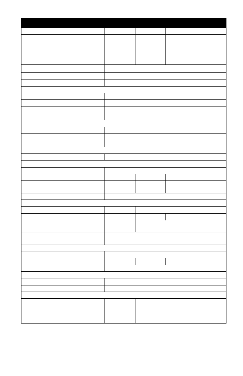
SPECIFICATIONS
Model Number 915236 915238 915240 915242
Model ZT-X 52
Engine Kawasaki
3
Engine Displacement – cm
Maximum RPM – No Load 3300 3300 ± 100
Oil Capacity Refer to Engine Manual
Drive
Forward Maximum – km/h (mph) 11.3 (7.0)
Reverse Maximum – km/h (mph) 4.8 (3.0)
Turning Radius Zero
Brakes Internal Transmission
Electrical
Starter Electric
Battery 12V Maintenance-Free 190CCA (U1 Replaceable)
PTO (Power Take-Off) Electric
Fuel
Fuel Tank Capacity – Liter (gal) 10.5 (2.8)
Size and Weight
Length – cm (in) 196.9 (77.5)
Width – cm (in) 161.0 (63.4) 137.7 (54.2) 161.0 (63.4) 181.6 (71.5)
Weight – kg (lbs.)
Height – cm (in) 103.9 (40.9)
Tires
Front Tire Size – in 11 x 4-5 11 x 6-5
Rear Tire Size – in 18 x 8.5-8 20 x 8-10 20 x 10-10 20 x 12-10
Recommended Front Tire
Pressure – kPa (psi)
Recommended Rear Tire
Pressure – kPa (psi)
Mower Deck
Cutting Height – cm (in) 3.8 – 11.4 (1.5 – 4.5)
Cutting Width – cm (in) 132.1 (52.0) 106.7 (42.0) 132.1 (52.0) 152.4 (60.0)
Mower Deck Lift Foot Operated
Towing
Max. Towing Capacity – kg (lbs) 136.0 (300.0)
Max. Tongue Weight – kg (lbs) 13.6 (30.0)
Transmission
Type Maintenance
(in3)
CARB
FR691V
CARB
279.0 (615.0)
317.2 (46.0) 206.8 (30.0)
-Free Hydro-
®
Gear
Transaxles
ZT-XL 42
CARB
Kawasaki
FR651V
CARB
726.0 (44.3)
299.8
(661.0)
Hydro-Gear® ZT2800 with charge pumps
EZT
ZT-XL 52
CARB
Kawasaki
FR691V
CARB
308.9
(681.0)
68.5 (10.0)
and external filter
ZT-XL 60
CARB
Kawasaki
FR730V
CARB
314.8 (694)
EN - 40
Page 43
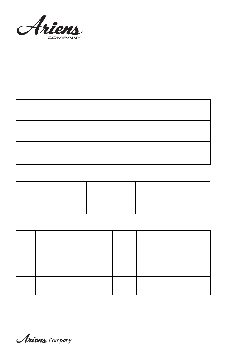
Consumer Mowing Equipment
Limited Warranty
Ariens Company (Ariens) warrants to the original purchaser that Ariens, Gravely and Countax brand
lawn and garden consumer products purchased on or after 9/1/2016 will be free from defects in material
and workmanship for the time period noted in the chart below. Equipment put to personal use around a
single household or residence is considered “Consumer Use”; equipment put to any business use
(agricultural, commercial, or industrial) or used at multiple locations is considered “Commercial Use.” If
any product is rented or leased, then the duration of these warranties shall be 90 days after the date of
purchase.
An authorized Ariens dealer (Ariens brand products), Gravely dealer (Gravely brand products), or
Countax dealer (Cou ntax brand prod ucts) will rep air any def ect in mater ial o r work manshi p, and r epai r or
replace any defective part, subject to the conditions, limitations and exclusions set forth herein. Such
repair or replacement will be free of charge (labor and parts) to the original purchaser except as noted
below.
Warranty
Code
Zoom, ZT, IKON-X, IKON-XL, ZT-X, ZT-XL
HA
Zero-Turn Riders
Apex, Max Zoom & ZT HD Zero-Turn
HB
Riders
"936" Tractors, "961" Series Walk-Behind
HC
Mowers
Classic LM Series Mowers; Wide Area
HD
Walk Mowers; Razor, XD3
N/A Service (replacement) Parts 90 Days (no labor) 90 Days (no labor)
AA Serialized Attachments 1 Year 1 Year
Product Group
Special Extensions
The chart below details special extensions to this warranty:
Warranty
Code
HA, HB
HA, HB
Warranty Exception
Mower Deck Shell on
Zero-Turn Riders
Main Frame on
Zero-Turn Riders
Warranty
Period
5 Years Consumer
5 Years Consumer
Warranty Period
Consumer Use
3 Years 90 Days
3 Years 1 Year
2 Years 90 Days
3 Years 90 Days
Use Detail
3 years parts and labor
Additional 2 years parts only
3 years parts and labor
Additional 2 years parts only
Warr
Warranty Period
Commercia l Use
Exceptions and Limitation s
The chart below details special exceptions to this warranty:
Warranty
Code
Warranty Exception
All Batteries 1 Year Consumer Prorated
All Belts, Muffler, Tires None Commercial
Cloth, Plastic, and
Rubber Components
All
(Including Belts and
Cables)
All Engines
Warranty
Period
Maximum
2 Years
See Engine
Manufacturer’s
Warranty
Use Detail
These components are not covered
when used commercially.
Warranty is limited to 2 years for
consumer use. Except as noted above,
All
these components are covered for
defect, not for wear.
Engines are covered by engine
manufacturer’s warranty. Refer to
All
engine manufacturer’s warranty
statement.
Customer Responsibilities
Register the product immediately at the time of sale. If the dealer does not register the product, the
customer must compl ete the pr o duc t r e gi st r ati on card in the literatur e pa c ka ge and r etu r n i t to the Ariens
Company, or register the unit online at www.ariens.com, www.gravely.com, www.countax.com.
To obtain warranty service, the original purch as er must:
• Perform the maintenance and adjustments explained in the owner's manual.
EN - 41
Consumer_2017
Page 44

• Promptly notify Arie ns or an au tho rized Ari ens, Grave ly or C ounta x ser vice re prese ntativ e o f t he ne ed
for warranty service.
• Transport the product to and from the place of warranty service at owner's expense.
• Have the warranty service performed by an authorized Ariens, Gravely or Countax service
representative.
To Find an Authorized Service Representative:
In the U.S. and Canada:
Use the dealer locator on our websites: www.ariens.com • www.g ravely.com
Or contact us by mail or by phone:
In the U.S., Ca n a da , M ex i co , Ca r i bb ea n,
Central and South America:
Ariens Company
655 W. Ryan Street
Brillion, WI 54110
Phone: (920) 756 - 4688
www.ariens.com
In Europe, Asia, Africa o r
the Middle East:
Ariens Company Limited
Great Haseley,
Oxford OX44 7PF
United Kingdom
Phone: +44 800 597 7777
www.countax.co.uk
In Australia or New Zealand:
Allpower Industries Pty Ltd
128 Bridge Rd
Keysborough VIC 3173
Australia
Phone: +61 1800 333 428
www.allpower.com.au
Exclusions – Items Not Covered by This Warranty
• Parts that are not genuine Ariens, Gravely or Countax service parts are not covered by this
warranty and may void the warranty.
• Damages resulting from the installation or use of any part, accessory, or attachment which is not
approved by the Ariens Company for use with product(s) identified herein are not covered by this warranty.
• The following maintenance, service and replacement items are not covered by this warranty unless
they are noted in the Limitations section above: lubricants, spark plugs, oil, oil filters, air
filters, fuel filters, brake linings, brake arms, brake shoes, skid shoes, scraper blades, shear bolts,
mower blades, mower vanes, brushes, headlights, light bulbs, knives, cutters.
• Any misuse, alteration, impro pe r as se m bl y, im pr o per a dj us tm en t, neglect, or acciden t which requires
repair is not covered by this warranty.
• Use of gasoline blends exceeding 10% ethanol voids any and all warranties.
• Products are designed to the specifications in the area that the product was originally distributed. Different areas may hav e si gnifi can tly dif fer ent l egal and de sig n requi rem ents. Thi s wa rrant y is lim ited t o
the requirements in the area in which the unit was originally distributed. Ariens Company does not
warrant this product to the requirements of any other area. Warranty service is limited to service
within the area originally distributed.
• In countries other than the United States and Canada, contact the Ariens Company dealer for
warranty policies that govern within your country. Rights may vary from country to country and within
any one country.
Disclaimer
Ariens Company may from time to time change the design of its products. Nothing contained in this
warranty shall be construed as obligating the Ariens Company to incorporate such design changes into
previously manufactured products, nor shall such changes be construed as an admission that previous
designs were defective.
LIMITATION OF REMEDY AND DAMAGES
Ariens Company 's liab ility under th is warr anty, and unde r any im plied wa rrant y that may exist, is lim ited to
repair of any defect in workmanship, and repair or replacement of any defective part. Ariens Company
shall not be liable for incidental, special, or consequential damages (including lost profits). Some states
do not allow the exclusion of incidental or consequential damages, so the above limitation or exclusion
may not apply to you.
AUSTRALIAN CONSUMER LAW
The following applies solely to warranties subject to Subsection 102(1) of the Australian Consumer Law:
Our goods come with guarantees that cannot be excluded by the Australian Consumer Law. You are
entitled to a replacement or refund for a major failure and for compensation for any other reasonably
foreseeable los s or da mage . You are also enti tled t o hav e the g oods repai red or r epla ced if the goods fail
to be of acceptable quality and failure does not amount to a major failure.
DISCLAIMER OF FURTHER WARRANTY
Ariens Company makes no warranty, express or implied, other than what is expressly made in
this warranty. If the law of your state provides that an implied warranty of merchantability, or an
implied warranty of fitness for particu lar purpos e, or any other im plied warranty , applies to A riens
Company, then any such implied warranty is limit e d t o t he duration of this warrant y. S ome states
do not allow limitations on how long an implied warranty lasts, so the above limitation may not
apply to you.
This warranty gives you specific legal rights, and you may also have other rights which vary from region to
region.
EN - 42
Consumer_2017
Page 45

Page 46

655 West Ryan Street
P
R
I
N
T
E
D
Brillion, WI 54110
gravelymower.com
gravely.custhelp.com
 Loading...