

Page 1

Promaster 252z / 260Z / 272Z
Owner/Operator Manual
Models
992066 - 25hp 52”
992067 - 25hp 60”
992068 - 27hp 60”
992069 - 28hp 60”
992070 - 25hp 72”
992071 - 27hp 52”
992072 - 27hp 72”
US Patent 6,301,864
ENGLISH
FRANÇAIS
ESPAÑOL
00264600 1/04
Printed in USA
Page 2
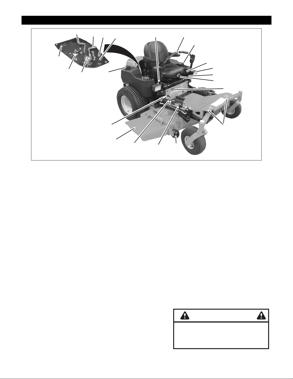
CONTROLS AND FEATURES
1
2
3
4
20
6
7
23
22
ENGLISH
1. Choke Control (Not on EFI* models)
2. Throttle Lever
3. Malfunction Indicator Light (EFI*
models only)
4. Oil Pressure Indicator
5. Fuel Tanks and Caps
6. Steering Levers
7. Eye-Q
8. Mower Lift Lever
9. Seat Suspension Adjustment Knob
10. Headlight
11. Seat Adjustment Lever
12. Fuel Shut Off Valve
13. Antiscalp Rollers
14. Axle Locks
15. Cylinder Stops
16. Height of Cut Indicator
17. Mower Deck with Chute Deflector
18. Cylinder Stop Storage Post
19. Foot Board Latch
20. Pa r ki ng Brak e
21. Power Take Off (PTO) Switch
22. Ignition Switch
23. Headlight Swi tch
*Electronic Fuel Injection
TM
21
5
19
17
16
Figure 1
FRANÇAIS
1. Starter (indisponible sur les modèles
EFI*)
2. Manette des gaz
3. Voyant d’anomalie (modèles EFI*
modèles uniquement)
4. Indicateur de pression d'huile
5. Réservoirs de carburant et bouchons
6. Leviers de direction
7. Eye-Q
8. Levier de relevage de la tondeuse
9. Levier de réglage de la suspension
10. Phare
11. Levier de réglage du siège
12. Robi net de carb ura nt
13. Rouleaux anti-scalp
14. Verrouillage de l’essieu
15. Butée s de vérin
16. Indicateur de hauteur de coupe
17. Carter de coupe avec déflecteur
18. Montant de remisage de butées de
19. Attache du repose-pied
20. Frein de stationnement
21. Contacteur de régime de la PdF
22. Contacteur de démarrage
23. Comm ande des phares
*Injection électronique
TM
vérin
15, 18
13
8
10
11
9
12
14
ESPAÑOL
1. Control de aire (no en modelos EFI*)
2. Palanca de ralentí
3. Lámpara indicadora de fallo
(solamente modelos EFI*)
4. Indicador de la presión del aceite
5. Tapas y depósitos de combustible
6. Palancas de dirección
7. Eye-Q
8. Palanca de elevación del cortacésped
9. Palanca de ajuste de la suspensión
10. Luces delanteras
11. Palanca de ajuste del asiento
12. Válvula de cierre de combustible
13. R odi ll os ant ide sb r oce
14. Trabas del eje
15. Topes de cilindro
16. Altura del indicador de corte
17. Plataforma de corte
18. Poste de almacenamiento del tope del
19. Traba de la plataforma de pie
20. Freno de estacionamiento
21. Interruptor de la toma de fuerza (TDF)
22. Interruptor de encendido
23. Interruptor de los faros delanteros
*Inyección electróni ca de com bu sti bl e
TM
cilindro
WARNING
The engine exhaust from this product
contains chemicals known to the State
of California to cause cancer, birth
defects or other reproductive harm.
2
Page 3

Page 4
TABL E OF CONTENTS
Controls and Features . . . . . . . . . . . . . . . . . . . . . 2
Safety . . . . . . . . . . . . . . . . . . . . . . . . . . . . . . . . . . . 5
Assembly . . . . . . . . . . . . . . . . . . . . . . . . . . . . . . . 10
Operation . . . . . . . . . . . . . . . . . . . . . . . . . . . . . . . 11
Maintenance Schedule . . . . . . . . . . . . . . . . . . . . 14
Service and Adjustments . . . . . . . . . . . . . . . . . . 17
INTRODUCTION
THE MANUAL
Before operation of unit, carefully and completely read
your manuals. The contents will provide you with an
understanding of safety instructions and controls during
normal operation and maintenance.
All reference to left, right, front, or rear are given from
operator sitting in the operation position and facing the
direction of forward travel.
SERVICE AND REPLACEMENT PARTS
Transfer
model &
serial
number
label from
product
registration
here.
When ordering publications ,
replacement parts, or making service
inquiries, know the Model and Serial
numbers of your unit and engine.
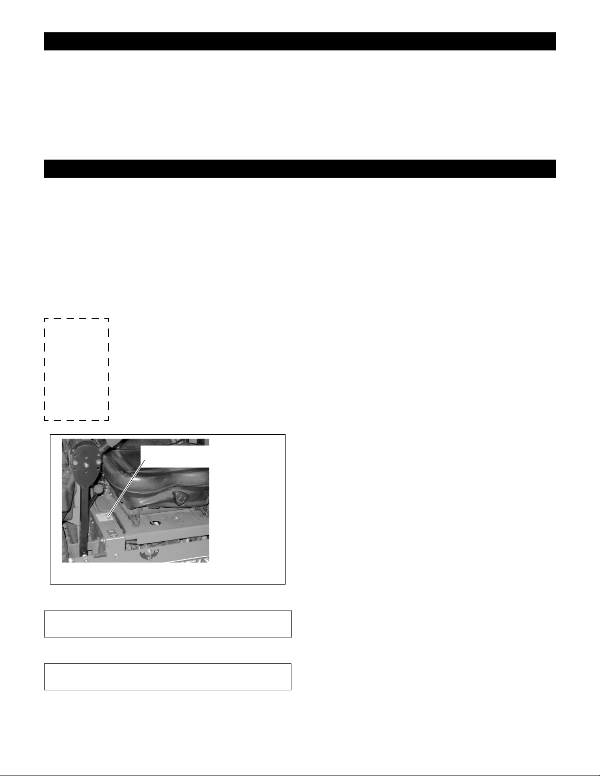
Numbers are located on the product
registration form in the unit literature
package. They are printed on a serial
number label, located on the frame of
your unit (Figure 2).
Serial Number Label
Storage . . . . . . . . . . . . . . . . . . . . . . . . . . . . . . . . 25
Accessories . . . . . . . . . . . . . . . . . . . . . . . . . . . . 26
Troubleshooting. . . . . . . . . . . . . . . . . . . . . . . . . 25
Service Parts . . . . . . . . . . . . . . . . . . . . . . . . . . . 26
Specifications. . . . . . . . . . . . . . . . . . . . . . . . . . . 27
Warranty . . . . . . . . . . . . . . . . . . . . . . . . . . . . . . . 28
PRODUCT REGISTRATION
The Gravely dealer must register the product at the time
of purchase. Registering the product will help the
company process warranty claims or contact you with the
latest service information. All claims meeting
requirements during the limited warranty period will be
honored, whether or not the product registration card is
returned. Keep a proof of purchase if you do not register
your unit.
Customer Note: If Dealer does not register your product,
please fill out, sign and return the product registration
card to Gravely.
UNAUTHORIZED REPLACEMENT PARTS
Use only Gravely replacement parts. The replacement of
any part on this equipment with anything other than a
Gravely authorized replacement part may adversely
affect the performance, durability, and safety of this unit
and may void the warranty. Gravely disclaims liability for
any claims or damages, whether regarding warranty,
property damage, personal injury or death arising out of
the use of unauthorized replacement parts.
NOTE: To locate your nearest Gravely Dealer, call
1-800-472-8359 or go to www.gravely.com on the internet.
Figure 2
• Record Unit Model and Serial numbers here.
• Record Engine Model and Serial numbers here.
OF3510
DISCLAIMER
Gravely reserves the right to discontinue, change, and
improve its products at any time without public notice or
obligation to the purchaser. The descriptions and
specifications contained in this manual were in effect at
printing. Equipment described within this manual may be
optional. Some illustrations may not be applicable to your
unit.
DEALER DELIVERY
Dealer should:
1. Test brakes after tractor is assembled to be sure
adjustment has not been disturbed in shipment
(See Parking Brake Interlock System on page 11).
Wheel brakes are properly adjusted at factory.
GB - 4
Copyright 2002 Ariens Company
Page 5
2. Check the safety interlock sys tem to make su re that
it is functioning properly . With operator on seat, unit
must not start unless steering levers are in neutral
(N) and Power Takeoff (PTO) is disengaged (Off).
Engine must stop if operator leaves seat when
steering levers are in any drive position or PTO is
engaged (On). See Safe ty Inte rloc k Syst em on
page 11.
3. Fill out Original Purchaser Registration Card and
return the card to Gravely.
4. Explain Gravely Limited Warranty Policy.
5. Explain recommended lubrication and
maintenance. Advise customer on adjustments.
SAFETY
Instruct customer on controls and operation of unit.
Discuss and emphasize the Safety Precautions.
Give customer Owner/Operator, Parts, and Engine
Manuals. Advise customer to thoroughly read and
understand them.
Customer Note: Your Dealer has been provided
complete set-up and preparation instructions which must
be completed prior to you taking delivery of this unit. The
dealer is required to review important information in this
manual with you before or upon delivery of the unit or
attachment.
WARNING: This cutting machine is capable of
amputating hands and feet and throwing
objects. Failure to observe the safety
instructions in the manuals and on decals could
result in serious injury or death.
Slopes are a major factor related to
loss-of-control and tip-over accidents. Operation
on all slopes requires extra caution.
Tragic accidents can occur if the operator is not
alert to the presence of children. Never assume
that children will remain where you last saw
them.
Gasoline is extremely flammable and the vapors
are explosive, handle with care.
Disengage attachment, stop unit and engine,
remove key, engage parking brake, and allow
moving parts to stop before leaving operator’s
position.
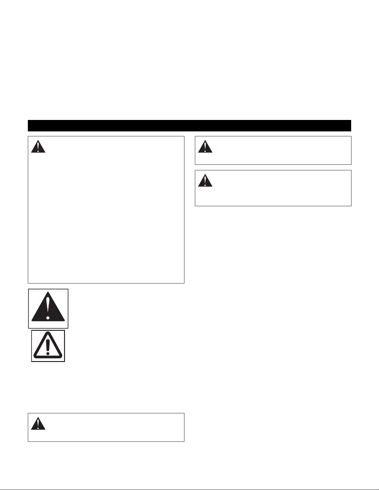
SAFETY ALERT SYMBOL
These are safety alert symbols. They
mean:
•ATTENTION!
OL1253
•YOUR SAFETY IS INVOLVED!
When you see this symbol:
•BECOME ALERT!
•OBEY THE MESSAGE!
OL3900
WARNING: POTENTIALLY HAZARDOUS
SITUATION! If not avoided, COULD RESULT in
death or serious injury.
CAUTION: POTENTIALLY HAZARDOUS
SITUATION! If not avoided, MAY RESULT in
minor or moderate injury. It may also be used to
alert against unsafe practices.
NOTATIONS
NOTE: General reference information for proper opera-
tion and maintenance practices.
IMPORTANT: Specific procedures or information
required to prevent damage to unit or attachment.
PRACTICES AND LAWS
Practice usual and customary safe working precautions,
for the benefit of yourself and others. Understand and
follow all safety messages. Be alert to unsafe conditions
and the possibility of minor, moderate, or serious injury or
death. Learn applicable rules and laws in your area,
including those that may restrict the age of the operator.
REQUIRED OPERATOR TRAINING
Original purchaser of this unit was instructed by the seller
on safe and proper operation. If unit is to be used by
someone other than original purchaser (loaned, rented or
sold), ALW AYS provide this manual and any needed
safety training before operation.
SIGNAL WORDS
The safety alert symbols above and signal words below
are used on decals and in this manual.
Read and understand all safety messages.
DANGER: IMMINENTLY HAZARDOUS
SITUATION! If not avoided, WILL RESULT in
death or serious injury.
GB - 5
Page 6

SAFETY DECALS AND LOCATIONS
ALWAYS replace missing or damaged Safety Decals.
Refer to Figure 3 for Safety Decal locations.
07742300B
7
Avoid injury - Stay clear of rotating parts.
Risque de blessures - ne pas sapprocher des pièces en
mouvement.
Evitar lesiones - Mantenerse alejado de las piezas giratorias.
DANGER / PELIGRO
07735200C
3
6
077560
5
DANGER/PELIGRO
07731400D
4
WARNING/AVERTISSEMENT/ADVERTENCIA
4
Do not operate mower
unless guards are in
operating position or
bagger is attached.
Ne jamais utiliser
la tondeuse sans
protecteur sur le
canal d'ejection ou
sans le bac monte.
No operar segadora a
menos que las defensas
esten en posicion de
operacion o el
recogedor este fijo.
1
2
3
DANGER/PELIGRO
05359400
07731400D
TO AVOID SERIOUS INJURY OR DEATH POUR EVITER LES BLESSURES GRAVES OU LA MORT PARA EVITAR DAÑOS SERIOS O LA MUERTE
Read the operator's manual.
Keep children and others away from unit while
operating.
Never direct discharge toward other people.
Thrown objects can cause injury.
Look down and behind before and while backing.
Never carry children.
Go up and down slopes, not across.
If machine stops going uphill, stop blade and
back down slowly.
Avoid sudden turns.
Keep safety devices (guards, shields, switches,
etc.) in place and working.
Check interlock system per manual before use.
Understand location and function of all controls.
Never allow operation by untrained persons.
Figure 3
DANGER / PELIGRO
Lire le manuel d'utilisation.
Éloigner les engants et tout autre personne pendant le fonctionnement de la
machine.
Ne jamais décharger directement en direction de quelquun. Des particules
projetées peuvent provoquer des blessures.
Regardez derriere et sur les cotes lorsque vous reculez.
Ne transportez jamais dénfant.
Tondez toujours de haut en bas et inversement jamais le long des pentes.
Si la machine sárrete en montee. Debrayez la lame et redescendez
doucement.
Evitez les virages brusques.
Maintenez toujours en place tous les elements de securite (protecteurs,
interrupteurs, etc.).
Controlez le bon fonctionnement des interrupteurs de securité avant
utilisation tel q'uindiqué dans le manuel d'utilisation.
Comprenez bien la fonction et la situation de chacun des leviers et boutons
de commande.
Never allow operation by untrained persons.
17
Leer el manual del operador.
Mantenga la unidad alejada de los niños u otras personas
cuando esté en funcionamiento.
Nunca dirija la descarga hacia otras personas, ya que los
objetos lanzados pueden provocar lesiones.
Antes y durante retroceso mirar hacia abajo y detras.
Nunca monten niños.
Suba y baje pendientes, no transversalmente.
Si la maquina se detiene subiendo cuesta, desactive la
cuchilla y baje lentamente.
Evite viradas subitas.
Mantenga artefactos de seguridad (defensas, protectores,
interruptores, etc.) en su lugar y trabajando.
Verifique en el manual el sistema de engranar antes de usar.
Tenga conocimiento de funciones y localizaciones de todos
los controles.
Never allow operation by untrained persons.
MAX
07734700D
OF3390
1. DANGER! TO AVOID SERIOUS INJURY
OR DEATH
Read Owner/Operator Manual.
OL1801
Keep children and others away from unit
while operating.
OL4370
Never direct discharge toward other people.
Thrown objects can cause injury . Remove
objects that could be thrown by the blade.
OL0910
Look down and behind before and while
backing.
OL4460
Keep children out of work area and under
watchful care of a responsible adult.
OL4470
NEVER CARRY CHILDREN.
OL4480
Go up and down slopes, not across.
DO NOT operate on slopes over 17°.
MAX
17°
OL4450
• If machine stops going uphill, stop blade and back
down slowly.
• Avoid sudden turns.
• Keep safety devices (guards, shields, switches, etc.)
in place and working.
• Check interlock system per manual before use.
• Understand location and function of all controls.
• Never allow operation by untrained persons.
GB - 6
Page 7
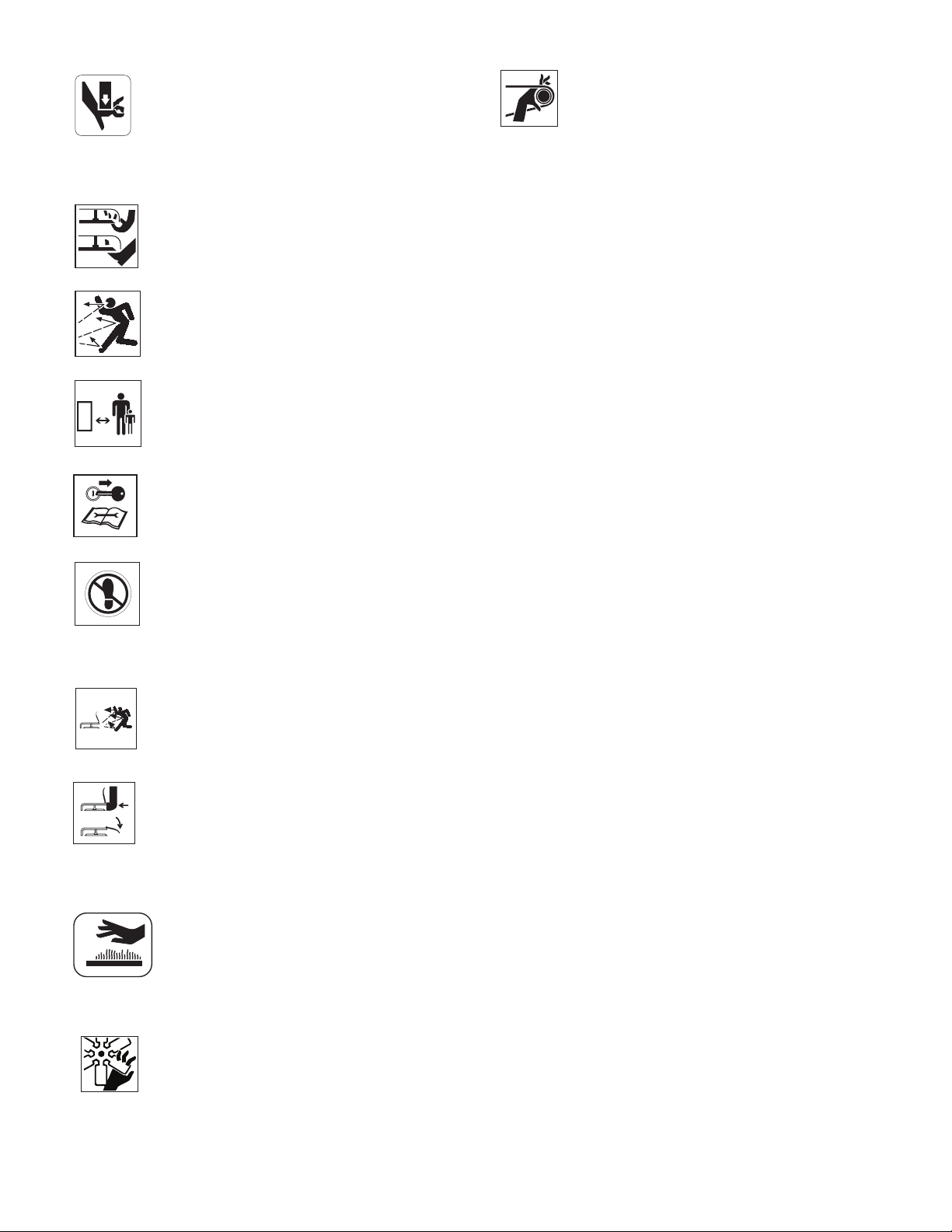
2. PINCH POINT
0
OL3292
Avoid pinch points.
7. DANGER!
AVOID INJURY. Stay clear of rotating parts.
OF333
3. DANGER! ROTATING PARTS
Always keep feet and hands away from
rotating parts.
OL3030
Always stand clear of discharge area. Do not
direct discharge toward other people.
OL0910
Keep people away from unit while operating.
Shut off engine, remove key, read manual
before you adjust or repair unit.
OL4010
NO STEP! Always keep feet away from
rotating parts.
OL4420
4. WARNING!
Always stand clear of discharge area.
OL4430
Do not operate mower unless bagger is
attached or guards are in operating position.
OL3320
5. HOT SURFACES!
DO NOT touch parts which are hot from
operation. ALWAYS allow parts to cool.
OS0731
6. ROTATING PARTS
AVOID INJURY. Stay clear of rotating parts.
OF3450
OL4730
SAFETY RULES
Read, understand, and follow all safety practices in
Owner/Operator Manual before beginning assembly.
Failure to follow instruction s co uld resu lt in pers onal
injury and/or damage to unit.
ALWAYS remove key and/or wire from spark plug before
assembly. Unintentional engine start up can cause death
or serious injury.
Complete a walk around inspection of unit and work area
to understand:
• Work area • Your unit • All safety decals
ALWAYS check overhead and side clearances carefully
before operation. ALWAYS be aware of traffic when
operating along streets or curbs.
Keep children and people away.
Keep children out of work area and under watchful care
of a responsible adult.
Keep area of operation clear of all toys, pets, and debris.
Thrown objects can cause injury.
Check for weak spots on docks, ramps or floors. Avoid
uneven work areas and rough terrain. Stay alert for
hidden hazards or traffic.
DO NOT operate near drop offs, ditches, or
embankments. Unit can suddenly turn over if a wheel is
over the edge of a cliff or ditch, or if an edge caves in.
Data indicates that operators, age 60 and above, are
involved in a larger percentage of riding mower related
injuries. These operators should evaluate their ability to
operate the riding mower safely enough to protect
themselves and others from serious injury.
Read the entire Owner/Operator manual and other
training material. If the operator or the mechanic cannot
read the manual, it is the owner’s responsibility to explain
it to them. Only the user can prevent and is responsible
for accidents or injuries occurring to themselves, other
people or property.
Only trained adults may operate or service unit.
Local regulations may restrict the age of the operator.
Training includes actual operation.
NEVER allow children to operate or play on or near unit.
Be alert and shut off unit if children enter area.
NEVER operate unit after or during the use of
medication, drugs or alcohol. Safe operation requires
your complete and unimpaired attention at all times.
DO NOT wear loose clothing or jewelry and tie back hair
that may get caught in rotating parts.
Wear adequate outer garments.
GB - 7
Page 8

NEVER wear open sandals or canvas shoes during
operation. Wear adequate safety gear, protective gloves
and footwear.
Wear proper footwear to improve footing on slippery
surfaces.
Always wear safety goggles or safety glasses with side
shields when operating mower.
Moving parts can cut or amputate fingers or a hand.
Wrap blade(s) or wear gloves to service. On multiblade
mowers, rotation of one blade will cause all blades to
rotate.
NEVER place your hands or any part of your body or
clothing inside or near any moving part while unit is
running.
ALWAYS keep hands and feet away from all rotating
parts during operation. Rotating parts can cut off body
parts.
ALWAYS keep body and hands away from pin holes or
nozzles which eject hydraulic fluid under pressure.
DO NOT touch parts which are hot. Allow parts to cool.
ALWAYS keep hands and feet away from all pinch
points.
Fumes from the engine exhaust can cause death or
serious injury. DO NOT run engine in an enclosed area.
Always provide good ventilation.
Read, understand, and follow all instructions in the
manual and on the machine before starting.
Understand:
• How to operate all controls
• The functions of all controls
• How to STOP in an Emergency
• Braking and steering characteristics
• Turning radius and clearances
Keep safety devices or guards in place and functioning
properly. NEVER modify or remove safety devices.
Ensure Safety Interlock System is functioning properly.
DO NOT operate unit if safety interlock is damaged or
disabled.
Start and operate unit only when seated in operator’s
position. Steering control levers must be in neutral, PTO
disengaged and parking brake set when starting engine.
Use care when approaching blind corners, shrubs, trees
or other objects that may obscure vision.
Dust, smoke, fog, etc. can reduce vision and cause an
accident. Mow only in daylight or good artificial light.
Avoid slippery surfaces. Always be sure of your footing.
DO NOT mow on wet grass. Reduced traction could
cause sliding and effect the machine’s stability.
Watch for traffic when operating near or crossing
roadways.
Never carry passengers.
DO NOT try to stabilize the machine by putting your foot
on the ground.
Never direct discharge towards persons or property that
may be injured or damaged by thrown objects. Use
extreme caution on gravel surfaces.
Always stand clear of the discharge area.
ALWAYS disengage PTO, stop unit and engine, remove
key, engage parking brake and allow moving parts to
stop before leaving operator’s position.
Never engage PTO while raising attachment or when
attachment is in raised position.
DO NOT operate at too fast a rate. DO NOT change
engine governor settings or over-speed engine. Slow
down before turning.
DO NOT operate i n revers e unle ss absol utely n ecessary.
ALWAYS look down and behind before and while
backing.
If equipment vibrates abnormally, stop engine at once,
wait for moving parts to stop and remove wire from spark
plug. Repair any damage before restarting unit.
Take all possible precautions when leaving unit
unattended. Shut off engine. Remove wire from spark
plug and secure it away from spark plug.
ALWAYS remove key to prevent unauthorized use.
Know the weight of loads. Limit loads to those you can
safely control and the unit can safely handle.
Disengage PTO when attachment is not in use. ALWAYS
turn off power to attachment when travelling, crossing
driveways, etc.
Mow up and down slopes, not across them.
DO NOT operate on slopes of more than 17 degrees.
Use of a Rollover Protection System (ROPS) is
recommended for slope operation. See Accessories on
page 26.
Always wear a seat belt when operating unit using a
Rollover Protection System (ROPS).
Keep all movements on the slope slow and gradual. Do
not make sudden changes in speed or direction.
Avoid starting or stopping on the slope. If tires lose
traction, disengage the blades and proceed slowly
straight down the slope.
If you cannot back up a slope or you feel uneasy on it, do
not mow it.
DO NOT park on slopes unless necessary. When parking
on slope always chock or block wheels. Always engage
parking brake.
Use a slow speed. Tires may lose traction on slopes
even though the brakes are functioning properly.
Do not bypass transmission when on a slope.
Use extra care when loading or unloading unit onto trailer
or truck.
GB - 8
Page 9

Secure unit chassis to transport vehicle. NEVER secure
from rods or linkages that could be damage d.
DO NOT transport machine while engine is running.
ALWAYS turn off power to attachment when transporting.
Keep unit free of debris. Clean up oil or fuel spills.
This product is equipped with an internal combustion
type engine. DO NOT use unit on or near any
unimproved, forest-covered or brush covered land unless
exhaust system is equipped with a spark arrester
meeting applicable local, state or federal laws. A spark
arrester, if it is used, must be maintained in effective
working order by operator.
Fuel is highly flammable and its vapors are explosive.
Handle with care. Use an approved fuel container.
NO smoking, NO sparks, NO flames. ALWAYS allow
engine to cool before servicing.
NEVER fill fuel tank when engine is running or hot from
operation.
NEVER fill or drain fuel tank indoors.
Replace fuel cap securely and clean up spilled fuel.
Never fill containers inside a vehicle or on a truck or
trailer bed with a plastic liner. Always place containers on
the ground away from your vehicle before filling.
When practical, remove gas-powered equipment from
the truck or trailer and refuel it on the ground. If this is not
possible, then refuel such equipment on a trailer with a
portable container, rather than from a gasoline dispenser
nozzle.
Keep the nozzle in contact with the rim of the fuel tank or
container opening at all times until fuelling is complete.
Do not use a nozzle lock-open device.
If fuel is spilled on clothing, change clothing immediately.
Avoid Electric Shock. Objects contacting both battery
terminals at the same time may result in injury and unit
damage. DO NOT reverse battery connections.
Explosive Gases from battery can cause death or serious
injury. Poisonous battery fluid contains sulfuric acid and
its contact with skin, eyes or clothing can cause severe
chemical burns.
No flames, No sparks, No smoking near battery.
ALWAYS wear safety glasses and protective gear near
battery.
DO NOT TIP battery beyond a 45° angle in any direction.
ALWAYS keep batteries out of reach of children.
Battery posts, terminals and related accessories contain
lead and lead compounds, chemicals known to the State
of California to cause cancer and reproductive harm.
Wash hands after handling.
ALWAYS block wheels and know all jack stands are
strong and secure and will hold weight of unit during
maintenance.
Release pressure slowly from components with stored
energy.
Keep nuts and bolts tight, especially blade attachment
bolts, and keep equipment in good condition.
NEVER attempt to make any adjustments to unit while
engine is running (except where specifically
recommended). Stop engine, remove key or spark plug
wire and wait for all moving parts to stop before servicing
or cleaning.
Check parking brake operation frequently. Adjust and
service as required.
ALWAYS maintain unit in safe operating condition.
Damaged or worn out muffler can cause fire or explosion.
NO smoking, NO sparks, NO flames. ALWAYS allow
engine to cool before servicing.
Maintain or replace safety and instructions labels, as
necessary.
NEVER store unit with fuel in fuel tank, inside a building
where any ignition sources are present.
Shut off fuel and allow engine to cool completely before
storing in closed area or covering unit.
Clean grass and debris from unit, especially from around
muffler and engine, to help prevent fires.
For extended storage, shut off fuel and clean unit
thoroughly. See engine manual for proper storage.
Lower cutting deck unless a positive mechanical lock is
used.
Use only attachments or accessories designed for your
unit.
Check attachment components frequently. If worn or
damaged, replace with manufacturer’s recommended
parts.
GB - 9
Page 10
ASSEMBLY
WARNING: AVOID INJURY. Read and
understand entire Safety section before
proceeding.
UNIT ASSEMBLY
Package Contents:
Unit, Mower Deck and Literature Pack
Preparation Checklist
Refer to the Owner/Operator manual as required.
1. Unpack Unit - Remove shrink wrap and packaging
materials.
2. Remove Unit From Container - Open Bypass
V alves (dump valves) (See Moving the Unit with the
Engine Off on page 14).
Push unit from container onto a level surface. Close
the dump valves.
3. Ti res - Adjust tire pressure for front tires: 20-25 PSI
(138-172 kN/m
(83-103 kN/m
4. Position and Attach Seat - Remove nuts from seat
studs in hood frame. Lift and rotate seat onto hood
frame. Secure with nuts.
5. Position Steering Levers - Remove bolts and
spacers from steering rod. Flip the steering levers
into operating position. Reinstall spacers, bolts and
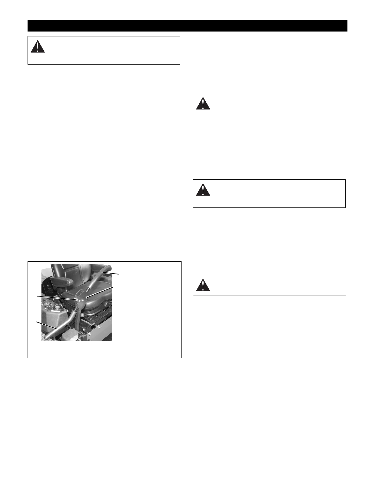
nuts. Tighten hardware securely. See Figure 4.
2
1
2
), rear tires: 12-15 PSI
2
).
3
2
1. Steering Lever in
2. Spacers and
3. Steering Lever in
Figure 4
Shipping Position
Hardware
Operation
Position
6. Battery - Remove battery from unit and charge (See
Battery on page 19).
7. Check Engine Crankcase - To access engine, open
hood. Check and add oil if needed. See Engine
Manual for specifications.
8. 60" and 72" Decks - Remove, reverse, and reinstall
discharge chute and mounting bracket.
WARNING: Discharge chute must pivot freely.
DO NOT overtighten the pivot bolts.
9. Fill Engine Fuel Tank - Add clean fuel to the fuel
tank.
IMPORTANT: Refer to Engine Manual for fuel type.
10. Hardware - Check for loose hardware.
11. Check Safety Interlock System - Check to see that
the interlock system operates correctly (See Safety
Interlock System on page 11).
WARNING: FAILURE OF INTERLOCK
together with improper operation can result in
severe personal injury.
12. Lubrication - Lubricate all fittings per maintenance
label under seat and check hydrostat oil level (See
Lubricate Unit on page 20).
13. Level Deck - Check unit to assure deck level set at
factory has been maintained (See Leveli ng the
Mower Deck on page 24).
14. Check Function of all Controls - Ensure unit runs
and performs properly.
WARNING: FAILURE OF CONTROLS could
result in death or serious injury.
OF3520
GB - 10
Page 11
OPERATION
WARNING: AVOID INJURY. Read and
understand entire Safety section before
proceeding.
CONTROLS AND FEATURES
See Figure 1 for Controls and Features locations.
Safety Interlock System
WARNING: Safety interlock system failure and
improper operation of unit can result in death or
serious injury. Test this system each time the
unit is operated. If this system does not function
as described, do not operate until repairs are
made.
Perform the following tests to ensure the safety interlock
system is working properly. If the unit does not perform
as stated, contact your Gravely dealer for repairs.
NOTE: When the parking brake is engaged, the steering
levers are locked in neutral.
T est Steering
Levers
1 Neutral Off Engaged Starts
2 Neutral On Engaged Doesn’t Start
3 Neutral Off Disengaged Doesn’t Start
OPERATING INTERLOCK (ENGINE ON)
4* Neutra l On Engaged Shuts Off
5* Neutra l Off Disengage d Shuts Off
* Operator lifts off seat.
Parking Brake Interlock System
With the parking brake engaged, the steering levers must
be locked in neutral.
With the parking brake disengaged, the engine must not
start and the engine must shut off if the operator leaves
the seat.
Eye-Q
TM
PTO Parking
Brake
STARTING INTERLOCK
Monitors equipment
performance, operator
performance, and equipment
maintenance. See Eye-Q
Owner’s Manual for how to
access these features.
Engine
Steering Levers
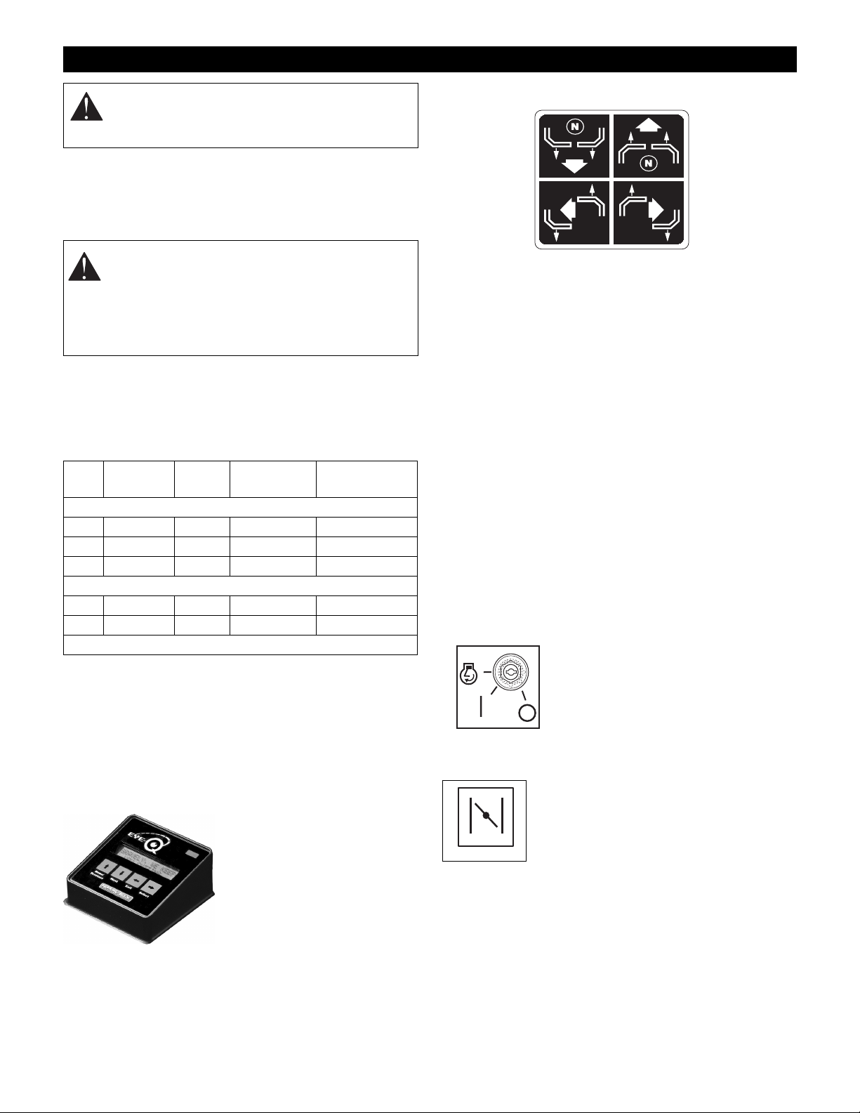
A
C
The steering levers control speed and direction. In
addition, they will stop the unit.
A. For reverse travel, pull both steering control levers
backward.
B. For straight forward travel, push both steering control
levers forward.
C. To turn left, pull the left back or push the right
steering control lever forward or a combination of
both.
D. To turn right, pull the right back or push the left
steering control lever forward or a combination of
both.
To stop, return both steering levers to neutral.
NOTE: The steering controls are mechanically locked in
neutral whenever the parking brake is engaged.
NOTE: Aggressive turning can scuff or damage lawns.
ALWAYS keep both wheels rotating when making sharp
turns. DO NOT make turns with inside wheel completely
stopped. To obtain minimum turning radius, slowly
reverse inside wheel while moving outside wheel slowly
forward.
3
Ignition Switch
Operate the ignition switch with the
removable key. The switch has three
positions: Off (1), On (2) and Start (3).
2
OF1751
1
To start the engine, turn the key to
Start, then release to On. To stop the
engine, turn the key to Off.
B
D
077348A
Choke Control (Not on EFI models)
Push the choke lever forward to start a
cold engine. Pull the choke lever to the
rear when the engine gets warm.
OF1680
GB - 11
Page 12
1
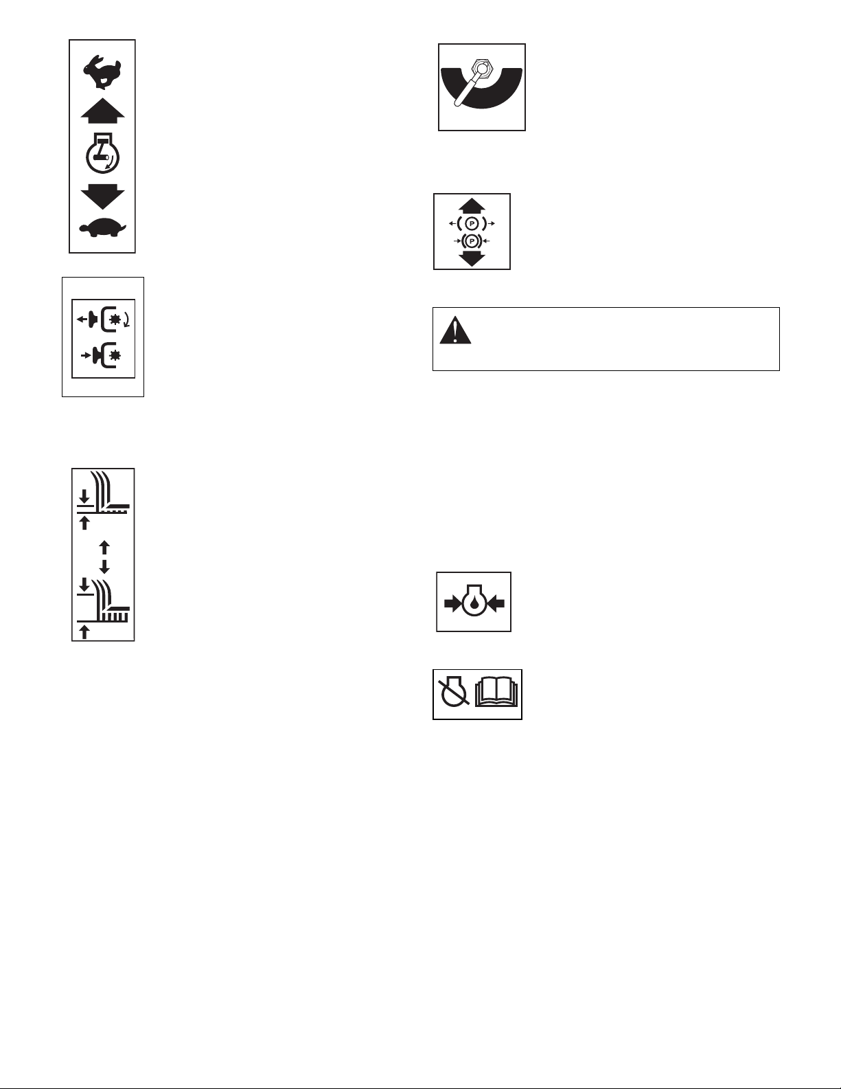
Throttle Lever
The throttle lever changes the engine
speed. Move the throttle lever to Fast (1)
to increase engine speed. Move the lever
to Slow (2) to decrease engine speed.
2
OF1700
ON
Power Take Off (PTO) Switch
Power take off (PTO) switch engages and
disengages the mower blades.
Pull the power take off (PTO) switch to
"On" position to engage mower blades.
OFF
"Off" position to disengage mower blades.
Push the power take off (PTO) switch to
OE0261
NOTE: The engine will not start unless the steering control levers are in the neutral position, the PTO switch is in
the “Off” position and parking brake is engaged.
Mower Lift Lever
Use the mowe r lift lever, located on the le ft
side of tractor, to raise and lower the
mower deck.
Pull the lever rearward to raise or push
the lever forward to lower the mower
deck.
Release lever to hold the mower deck in
selected position.
OF1700
The cutting height indicator on the right lift
cylinder shows the approximate cutting
height in inches.
Cylinder Stops
The cylinder stops ensure the same cutting height after
raising the deck to clear an obstacle. Store the stops on
the post behind the hydraulic lift cylinder. The stops come
in two (2) sizes, 1/4" (.64 cm) and 1/2" (1.27 cm).
1. Remove the cylinder stops from the post and snap
onto the lift cylinder rod.
2. Push the lift lever forward until the cylinder rests
against the cylinder stops.
Fuel Shut-Off Valve
OFF
RIGHT
TANK
OF1881
Use this valve to control fuel flow from
LEFT
TANK
left or right fuel tank.
Open the valve to operate the engine.
Turn the valve to "Off" when storing or
transporting the unit.
NOTE: Fuel shut-off valve on EFI units
does not have an "Off" position.
Parking Brake Lever
1. Pull lever up to engage parking brake.
2. Push lever down to disengage parking
brake.
OF1740
Seat Adjustments
WARNING: Make all seat adjustments with unit
stationary, parking brake engaged and engine
shut off.
To adjust seat forward or backward:
1. While seated, pull seat adjustment lever outward
and slide seat into desired position.
2. Release lever and slide seat forward or back to lock
seat into position.
To adjust seat suspension:
• To make seat more firm turn knob clockwise. To
make seat less firm turn knob counter clockwise.
Turn knob several turns at a time until desired
position is achieved.
Engine Oil Pressure Indicator
Indicator lights up “Red” if the oil pressure
is low. Check oil level and add if
OG0601
necessary. Refer to engine manual.
Malfunction Indicator Light (EFI models only)
The malfunction indicator light flashes
when there is a problem with the
electronic fuel injection system. When
OD0190
indicator light flashes, disengage PTO,
shut off engine, remove key and see engine manual.
Axle Locks
For a solid front axle, install axle locks on front axle. For a
pivoting front axle, remove axle locks from front axle and
store on unit.
Headlights
Push headlight switch to ON position to turn ON
headlights. Push headlight switch to OFF position to turn
OFF headlights.
GB - 12
Page 13

FILLING FUEL TANK
WARNING: AVOID INJURY. Read and
understand entire Safety section before
proceeding.
Add fuel to Fuel Tank as needed. See your Engine
Manual for correct type and grade of fuel.
To add fuel to the fuel tank:
1. Place unit in an open or well-ventilated open area.
2. Stop the engine.
3. Clean the fuel cap and the area around the fuel cap
to prevent dirt from entering the fuel tank. Remove
the cap from the fuel tank.
4. Fill the fuel tank to within 1" (25 mm) below bottom
of filler neck.
5. Replace fuel cap and tighten.
6. Clean up any spilled fuel.
PRE-START
CAUTION: Make sure all hardware is tight, all
safety devices are in place and all adjustments
are made correctly.
1. Check Safety Interlock System
If this system does not function as described do not
operate until repairs are made.
2. Check Air Cleaner
Check air filter for dirt. Clean as required. See
Maintenance Section.
3. Check Engine Fuel and Crankcase Oil
Check and add fuel if required. Check that engine
crankcase oil is full. Refer to Maintenance Section.
4. Check Tire Pressure
5. Check Hydraulic Fluid Level
6. Adjust Seat
Be sure all controls can be reached safely from
operator’s position.
STOPPING IN AN EMERGENCY
The unit can be stopped immediately at any time by
turning the ignition key to the "Off" position.
STARTING AND SHUT OFF
CAUTION: Read entire Owner/Operator
Manual, Clutch Manual, and Engine Manual
first.
DO NOT attempt to start engine at this time.
To start the engine:
1. Make sure the steering levers are in neutral.
2. Put the PTO switch in the “Off” position.
3. Engage parking brake.
4. For models with choke:
If the engine is cold, move the choke control to the
“On” position. If the engine is warm or hot, do not
use choke.
5. Move the throttle to 3/4 “Fast” position. See Engine
Manual for detailed instructions.
6. Put the ignition key in the switch and turn it to the
“Start” position.
7. As soon as the engine starts, release the key.
8. For models with choke:
Move the choke control to the “Off” position from
the “Choke” position. Wait until the engine is
running smoothly before operation.
To stop the engine:
1. Bring the steering levers to neutral. Disengage the
PTO and engage the parking brake.
2. Move the throttle lever to the “Slow” position.
3. Turn the ignition key to the “Off” position.
TO MOW WITH UNIT
Operate the unit only when seated in the operator’s
position.
1. Start the engine. Let the engine warm until it is
running smoothly.
2. Release parking brake.
WARNING: Move the steering control levers
slowly and keep the throttle control lever at slow
speed until you learn how to operate the unit.
3. Bring the steering levers to neutral.
4. Slow the engine down to about 3/4 speed.
5. Turn ON the PTO switch to engage the mower.
IMPORTANT: Never engage the PTO if the mower is
plugged with grass or other material. This may cause
damage to the electric clutch.
6. Move throttle control to fast.
7. Move the steering levers forward to obtain a slow
ground speed.
8. To disengage the mower, move the PTO switch to
the “Off” position.
9. When you know how to operate the unit, select a
speed appropriate to your mowing conditions.
PARKING
To park the unit:
1. Bring the steering levers to neutral. Turn off PTO.
2. Move the throttle lever to the “Slow” position.
3. Engage the parking brake.
GB - 13
Page 14
4. Lower the attachment.
5. Turn the ignition key to the “Off” position and
remove the key.
MOVING THE UNIT WITH THE ENGINE OFF
IMPORTANT: Never tow unit.
1. Shut OFF engine.
2. Place seat in the service position. See Service
Positions on page 17.
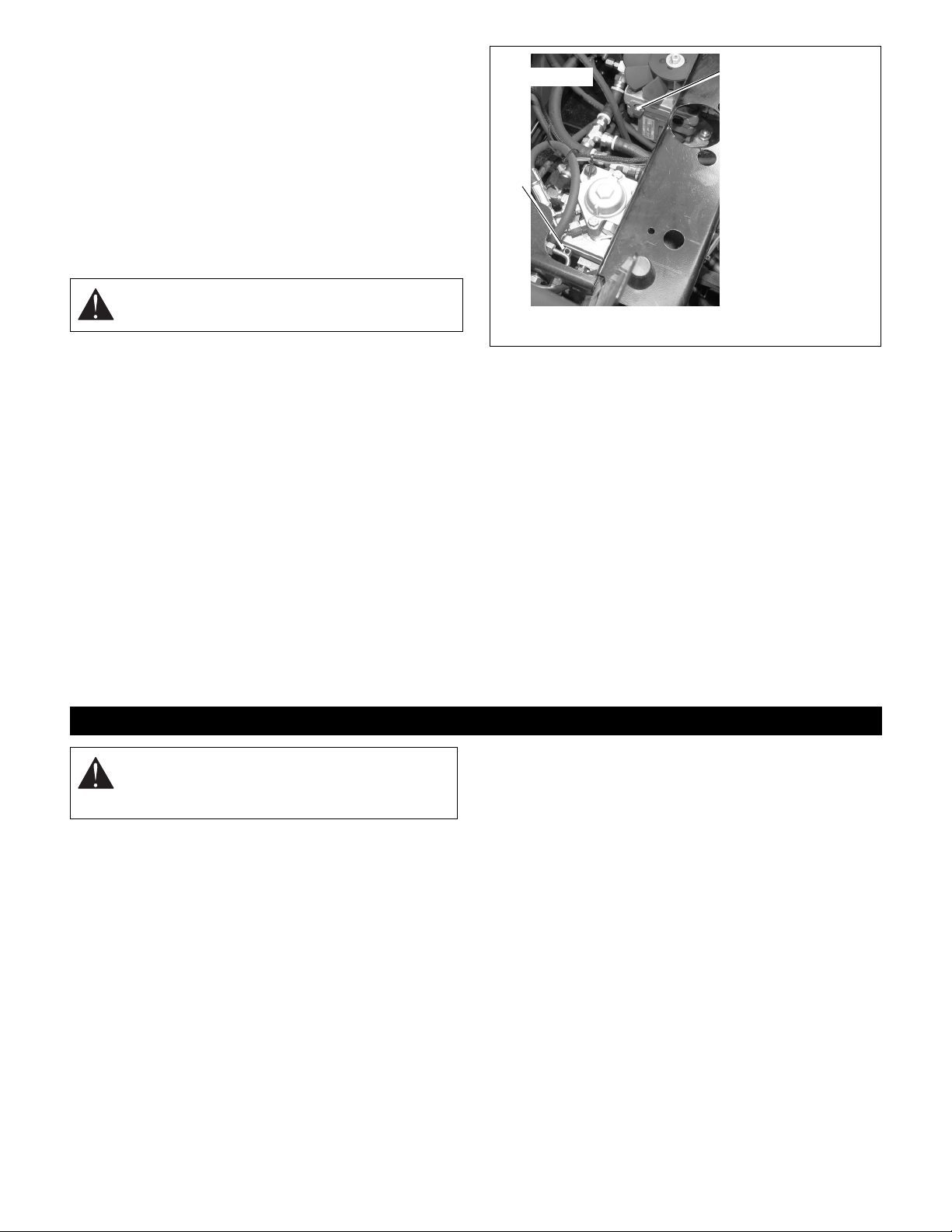
3. Turn right and left bypass valve levers counter
clockwise 1/2 turn (Figure 5).
WARNING: Do not bypass transmission when
on a slope.
4. Disengage parking brake.
5. Push unit to desired location.
6. Engage parking brake.
7. Turn bypass valve levers clockwise 1/2 turn.
Front of unit
2
1
1. Left Bypass
Valve Lever
2. Right Bypass
Valve Lever
Figure 5
OF3530
FOR BEST PERFORMANCE
Cut grass when it is dry.
Keep mower blades sharp.
Keep mower deck properly level ed.
Adjust anti-scalp rollers to prevent scalping.
Do not set height of cut too low. For very tall grass, mow
twice.
Do not travel too fast.
Mow with the engine set at full throttle.
When mulching, only remove 1/3 of grass length per
cutting.
Discharge clippings into areas already cut.
Vary cutting pattern with each mowing.
Do not allow grass or debris to collect inside of mower
deck. Clean after each use.
MAINTENANCE SCHEDULE
WARNING: AVOID INJURY. Read and
understand entire Safety section before
proceeding.
Proper maintenance can prolong the life of unit. The
following charts show the recommended service
schedule. More frequent service may be required due to
working conditions (heavy loads, high ambient
temperatures, dusty conditions, or airborne debris).
See the maintenance instructions in the Engine Manual
for additional information.
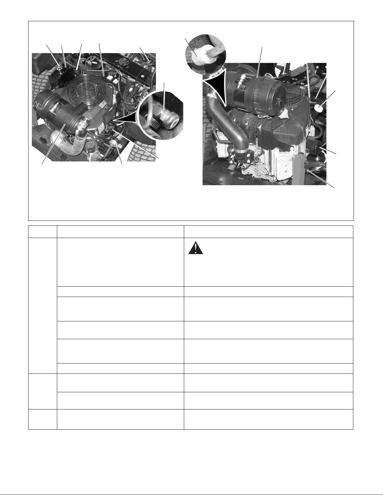
NOTE: Use Figure 6 for maintenance item locations.
GB - 14
Page 15
Kohler Engine Kawasaki Engine
4
2
1
3
5
5
9
6
3
7
9
1. Hydraulic Fluid
Cap/Dipstick
2. Hydraulic Fluid Tank
3. Oil Fill/Dip sti ck
4. Battery
8
5. In-Line Fuel Filter
6. Oil Drain Petcock
7. Oil Filter
8. EFI Fuel Filter
9. Air Filter
Figure 6
Period Service Task
Check Safety Interlock
Check Parking Brake Interlock System See Parking Brake Interlock System on page 11.
Each
Use
Check Engine Oil Check oil level on dipstick (item 3). Add more oil through the
engine oil fill cap if needed. See engine manual for detailed
instructions.
Check Air Filter Check the air cleaner element (item 9) before each use. See
engine manual for detailed instructions.
7
6
OF3540
OF3550
WARNING: Safety interlock system failure and
improper operation of unit can result in death or
serious injury. Test this system each time the unit is
operated. If this system does not function as
described, do not operate until repairs are made.
See Safety Interlock System on page 11.
Every 25
Hours
Every 50
Hours
Check Hydraulic Fluid Check hydraulic oil level mark on cap/dipstick (item 1). Add
15W50 Synthetic oil as needed. Do not overfill. See Hydraulic
Fluid on page 17.
Check Tires See Specifications on page 27 for correct tire pressure.
Check Mower Blades
Clean Air Filter Outer Element (992066, 067,
070)
Lubricate Unit Oil all pivot points and pin connections. Grease lube fittings. See
Check mower blades for wear. Sharpen or replace as needed.
See Mower Blades on page 18.
Clean the outer filter element (item 9). Replace as needed. Refer
to engine manual for detailed instructions.
Lubricate Unit on page 20.
GB - 15
Page 16

Period Service Task
Clean Battery Keep battery (item 4) and its terminals clean. See Clean Battery
on page 19.
Change Engine Oil Drain oil by opening oil d rain petc oc k (i tem6) on right sid e of u nit.
Refer to engine manual for detailed instructions.
Every
100
Hours
Every
200
Hours
Every
250
Hours
Every
500
Hours
Every
1,500
Hours
Clean Air Filter Inner Element (99 2066, 0 67, 070) Clean the inner filter element (item 9).
Check Fasteners Check mower blade mounting hardware and all other fasteners.
Replace missing or damaged fasteners. Tighten all nuts and bolts
to their correct torque value.
Check Belts Replace worn or deteriorated belts. See Replacing Mower Belt s
on page 22 and Replacing the Hydro Pump Belt o n page 23.
Change Fuel Filter Change in-line fuel filter (item 5). Refer to engine manual for
detailed instructions.
Change Oil Filter Change oil filter (item 7). Refer to engine manual for detailed
instructions.
Replace Air Filter Inner Element (992066, 067,
070)
Replace Air Filter Outer Element (992068, 069,
071, 072)
Change Hydraulic Fluid and Filter Drain hydraulic fluid tank (item 2), replace hydraulic oil filter, refill
Replace Air Filter Inner Element (992068, 069,
071, 072)
Change EFI Fuel Filter (992069 only) Replace canister fuel filter (item 8) on frame. Refer to engine
Replace the inner filter element (item 9). Refer to engine manual
for detailed instructio ns .
Replace the outer filter element (item 9). Refer to engine manual
for detailed instructio ns .
system. See Change Hydraulic Fluid and Filter on page 18.
Replace the inner filter element (item 9). Refer to engine manual
for detailed instructio ns .
manual for detailed instructions.
GB - 16
Page 17
SERVICE AND ADJUSTMENTS
d
Gravely Dealers will provide any service wh ich may be
required to keep your unit operating at peak efficiency.
Should engine service be required, it can be obtained
from a Gravely Dealer or the engine manufacturer’s
authorized service center.
WARNING: AVOID INJURY. Read and
understand entire Safety section before
proceeding.
CAUTION: HOT SURFACES may result in
injury. DO NOT touch engine or drive parts
which are hot from operation. Allow parts to cool
before servicing.
SERVICE POSITIONS
1. Place unit on a flat level surface. ALWAYS stop
engine. Ensure unit is secure and will not tip over.
Strap and clamp onto lift if used.
2. Place steering levers in neutral position and engage
parking brake.
3. Unhook hood latches.
4. Firmly grasp engine frame and cover. Lift to desired
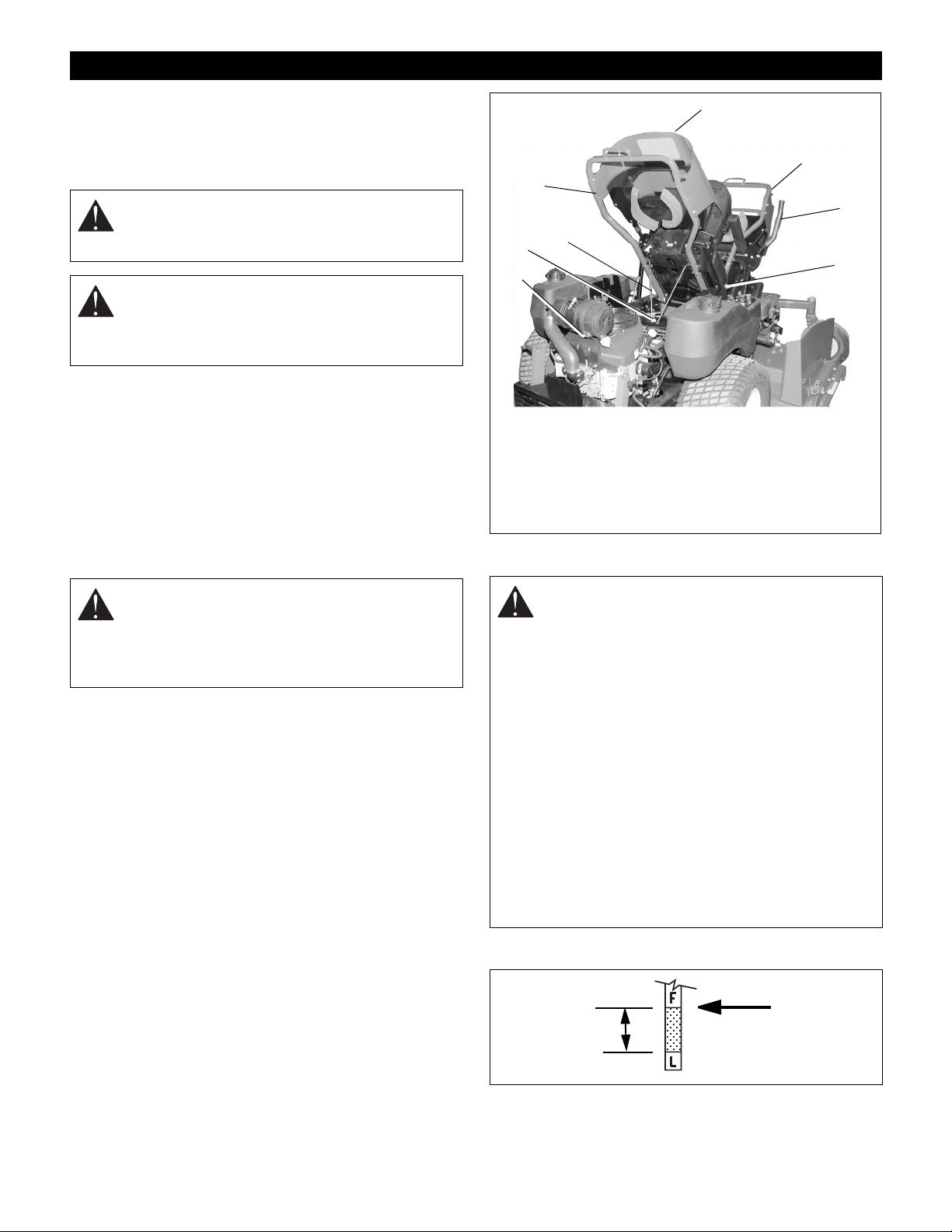
service position (Figure 7).
8
7
6
5
1. Daily Ser vice Position
2. Full Service Position
3. Steering Lever s
4. Parkin g Brake
HYDRAULIC FLUID
1
2
3
4
OF3560
5. Engine
6. Service Slot
7. Engine Hood Prop Ro
8. Engine Hood & Frame
Figure 7
CAUTION: W HEN OPENING ENGINE COVER ,
USE CARE TO PROPERLY ENGAGE PROP
INTO SLOT. Be sure footing is secure to
accomodate weight shift of hood when rotating
to full service position.
Daily Service Position: Place engine hood prop rod into
service slot. Assure rod is engaged in slot properly.
Full Service Position: Slowly release frame after seat
contacts foot board. Use care and be sure of your footing.
Do not step on mower deck.
5. When service is complete, lower hood and secure
with latches.
WARNING: HYDRAULIC FLUID can result in
severe burns. Fluid in hydraulic system can
penetrate skin and result in serious injury or
death.
Be sure to stop the engine before doing any
work on hydraulic parts.
Keep body and hands away from pin holes or
nozzles which expel hydraulic fluid when under
pressure. Use paper or cardboard, not hands, to
search for leaks.
Ensure all hydraulic fluid connections are tight
and all hydraulic hoses and lines are in good
condition before applying pressure to system.
FOREIGN FLUID INJECTED INTO BODY can
result in gangrene. Fluid must be surgically
removed within a few hours by a doctor familiar
with this form of injury.
Check Hydraulic Fluid Level
FULL Mark
Operating
Range
OE0380
1. Shut OFF engine. Engage parking brake. Remove
the ignition key.
GB - 17
Page 18
2. Put seat in service position.
3. Remove any dirt that may be around the
cap/dipstick on the hydraulic reser voir.
4. Remove cap/dipstick.
5. Check hydraulic oil level mark on cap/dipstick.
6. Add 15W50 Synthetic oil as needed. Do not overfill.
Change Hydraulic Fluid and Filter
Change the hydraulic oil filter and hydraulic oil every 500
hours. Use Mobil 15W50 synthetic oil for best component
life.
1. Clean around dipstick cap and dipstick. Remove
dipstick.
2. Place container under oil filter to catch oil.
3. Remove oil filter.
4. Allow tank to drain.
5. Lubricate rubber gasket on new oil filter with clean
hydraulic oil.
6. Spin new oil filter onto filter housing until it makes
contact. Tighten oil filter another 1/2 turn.
7. Add new oil to the oil tank. It will take about 4
quarts. Use Mobil 15W50 synthetic oil for best
pump and wheel motor life.
8. Properly dispose of waste oil.
Discard mower blade if:
• More than 1/2 in. (1.27 cm) of metal is removed.
• Air lifts become eroded.
• Blade is bent or broken.
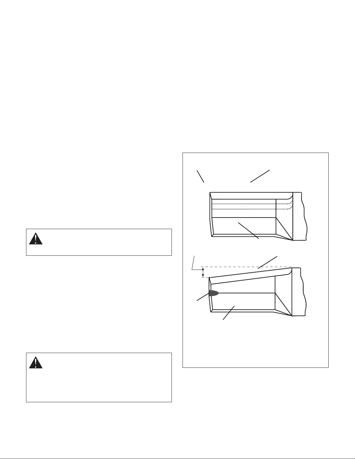
2. Sharpen mower blade by removing an equal
amount of material from each end of mower blade.
DO NOT change angle of cutting edge or round the
corner of the mower blade.
3. Check mower blade balance.
Slide mower blade on an unthreaded bolt. A
balanced blade should remain in a horizontal
position. If either end of mower blade moves
downward, sharpen the heavy end until blade is
balanced.
4. Install mower blade(s) on unit.
5. Tighten the bolts to a torque of 115-120 lbf-ft
(156-162.6 N•m).
DO NOT Sharpen to This Pattern
2
1
MOWER BLADES
Remove
CAUTION: Use sturdy gloves or padding to
protect hands when working with mower
blades.
1. Turn the engine off. Remove the ignition key.
Remove the ignition wire from the spark plugs.
2. Remove the bolts, lock washer, flat washers, and
blades from the spindle shafts.
Replace
1. Put the blades, flat washers, lock washers, and the
bolts back on the spindle shafts.
2. Tighten the bolts to a torque of 115-120 lbf-ft
(156-162.6 N•m).
3. Replace the ignition wire on the spark plugs.
Sharpen the Mower Blades
CAUTION: DO NOT sharpen mower blades
while on unit. An unbalanced mower blade will
cause excessive vibration and eventual
damage to unit. Check mower blade balance
before reinstalling blades.
NEVER weld or straighten bent blades.
DISCARD if More
Than 1/2 in. (1.27 cm)
3
4
Sharpen to This Pattern
1. Cutting Edge
2. Square Corner
4
1
OT0792
3. Air Lift Erosion
4. Air Lift
Figure 8
1. Remove mower blade from unit.
GB - 18
Page 19
BATTERY
WARNING: AVOID INJURY. Read and
understand entire Safety section before
proceeding.
WARNING: Battery posts, terminals and related
accessories contain lead and lead compounds,
chemicals known to the State of California to
cause cancer and reproductive harm. Wash
hands after handling.
Unit comes equipped with a maintenance-free battery
that requires no regular maintenance except cleaning the
terminals.
Remove Battery
1. Shut OFF engine. Engage parking brake. Remove
the ignition key.
2. Place seat in the service position (See Service
Positions on page 17 in Maintenance).
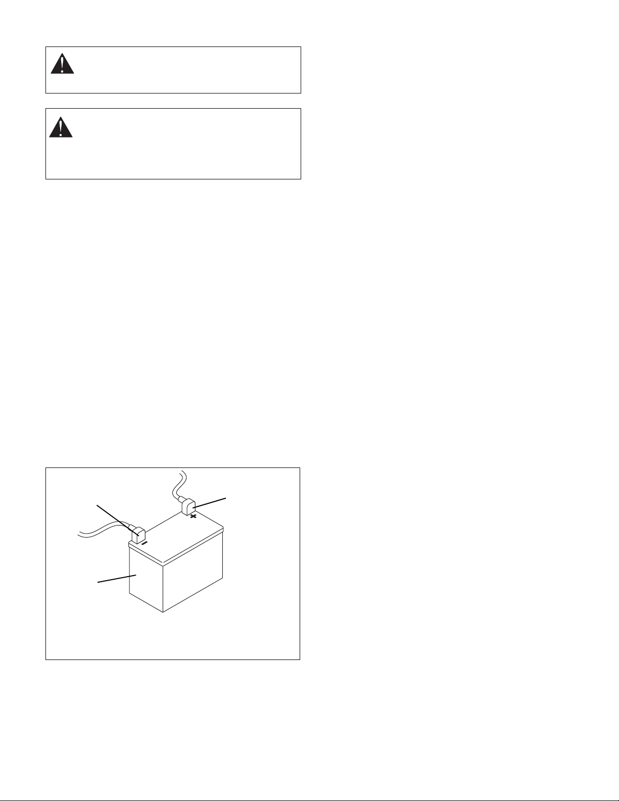
3. Disconnect cables from battery (negative, then
positive) (Figure 9).
4. Remove hold down and remove battery.
Replace Battery
1. Replace battery and secure with battery hold down.
2. Reconnect cables to battery (positive, then
negative). Position boot over positive terminal.
3. Return seat to operating position.
Clean Battery
Keep battery and its terminals clean. Inspect every 100
operating hours or monthly for best performance.
1
3
1. Negative terminal
2. Positive terminal
3. Battery
Figure 9
1. Remove battery from unit. See Remove Battery on
page 19.
2. Clean terminals and battery cable ends with wire
brush.
2
OF1671
3. Coat terminals with dielectric grease or petroleum
jelly.
4. Replace battery. See Replace Battery on page 19.
Charging the Battery
Battery Electrolyte First Aid
Follow First Aid directions for contact with battery fluid.
• External Contact: Flush with water.
• Eyes: Flush with water for at least 15 minutes and
get medical attention immediately!
• Internal Contact: Drink large quantities of water.
Follow with Milk of Magnesia, beaten egg or
vegetable oil. Get medical attention immediately!
In case of internal contact, DO NOT induce vomiting!
IMPORTANT: DO NOT fast charge. Charging at a higher
rate will damage or destroy battery. ONLY use an
automatic charger designed for use with your battery.
ALWAYS follow information provided on battery by
battery manufacturer. Contact battery manufacturer for
extensive instructions to charge battery.
1. Remove battery from unit. See Remove Battery on
page 19.
2. Place battery on bench or other well-ventilated
place.
3. Connect positive (+) lead of charger to positive (+)
terminal, and negative (–) lead to negative (–)
terminal.
4. Charge battery according to charger and battery
manufacturers’ instructions.
5. Replace battery. See Replace Battery on page 19.
Jump Starting Batter y
IMPORTANT: DO NOT jump start battery on model
992069. Failure to comply will void the engine warranty
and can damage the engine.
The unit used for jump starting should have a 12 volt
battery with at least 500 cold cranking amperes, and a
negatively grounded system.
NOTE: Ensure battery is not frozen. If the fluid is frozen,
remove battery from unit and allow it to thaw before
charging.
1. Connect the positive (+) jumper cable to the
positive terminal of the discharged battery (Figure
9).
2. Connect the other end of the same jumper cable to
the positive (+) terminal of the booster battery.
3. Connect one end of the second jumper cable to the
negative (–) terminal of the booster battery.
4. Make the final jumper cable connection to the
engine block or the furthest ground point away from
the discharged battery.
GB - 19
Page 20
WARNING: Make sure cables are clear of any
moving engine parts before starting engine.
5. Start engine (refer to Operation Section). If engine
will not start after several tries, unit or battery may
need service.
6. After engine starts, leave cables connected for one
to two minutes.
7. Disconnect cables in reverse order.
8. Operate unit as normal to charge battery.
LUBRICATE UNIT
IMPORTANT: Wipe each fitting clean before and after
lubrication.
Steering system and Speed Selector components should
be lubricated every 50 hours of operation or every
3 months whichever comes first (Figure 10).
Lube fitting locations are:
– front axle pivot (2)
Apply Stens Mix Hi-Temp Grease or equivalent to the
lube fittings. Order P/N: 00036700 - ten pack of 14 oz.
cartridges.
When using Stens Mix Grease for the first time, all
components should be thoroughly cleaned prior to
lubricating.
Apply oil at all pivot points and pin connections.
STEERING CONTROL NEUTRAL
ADJUSTMENT
If the steering levers do not line up (match) or the unit
has excessive creeping when the steering levers are in
neutral, adjust as follows.
Adjusting the Steering Levers to Line Up
(Match) (Figure 11)
1. Shut OFF engine. Engage parking brake. Remove
the ignition key.
2. Place seat in the service position (See Service
Positions on page 17 in Maintenance).
3. Loosen damper locknut on the same side as the
steering lever to be adjusted.
4. Loosen brake interlock on the same side as
steering lever to be adjusted.
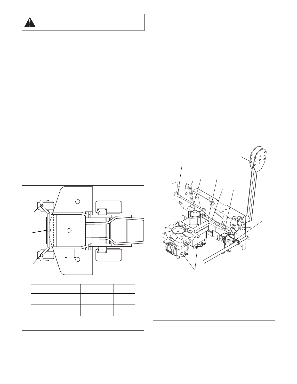
5. Loosen tie rod jam nut and turn tie rod until steering
levers are aligned.
6. Ti ghten jam nut on tie rod, tighten brake interlock
and tighten damper locknut.
5
1
2
3
1
2
1
REF LUBRICATION QTY DESCRIPTION-
1 REPACK 2 CASTER PIVOT 400 Hrs
2 GREASE 1 AXLE PIVOT 50 Hrs
OIL ALL PIVOT POINTS,
LOCATION
PIN CONNECTIONS
Figure 10
INTERVAL
50 Hrs
OF1792
7
1. Damper Locknut
2. Damper
3. Tie-Rod Jam Nut
4. Tie-Rod
Figure 11
4
3
5. Steering Lever
6. Brake Interlock
7. Hydrostatic
Transmission
6
OF3381
GB - 20
Page 21
Eliminating Excessive Creeping of the Unit
(Figure 11)
WARNING: This adjustment requires operating
the engine. Use extreme care to avoid contact
with moving parts and hot surfaces. Be sure
rear of unit is well supported and secure before
starting engine.
1. If hydraulic system is cold, run unit for a minimum of
five minutes, then shut OFF engine.
2. With the unit up to and facing a wall, jack the unit up
so that both drive wheels are off the ground.
3. Start the engine and release the parking brake.
4. Move the steering levers from Forward to Reverse
several times to make sure controls are free. Then
return steering levers to neutral position.
5. Check wheel(s) for mo vement.
6. Shut OFF engine.
NOTE: The right and left steering levers are adjusted the
same way. To access the tie-rod, place seat in service
position.
7. Adjust tie-rod(s):
If the wheel is moving in a forward direction:
a. Loosen the jam nut on each end of the tie-rod.
b. Turn tie-rod counterclockwise (lengthening the
distance between the steering lever and
hydrostatic transmission) several times.
If the wheel is moving in a reverse direction:
a. Loosen the jam nut on each end of the tie-rod.
b. Turn tie-rod clockwise (decreasing the distance
between the steering lever and hydrostatic
transmission) several times.
8. Return seat to operating position.
9. Start e ngine.
10. Move steering levers from Forward to Reverse
several times. Then return steering levers to neutral
position.
11. Shut OFF engine.
12. If wheel is not moving, tighten jam nuts on tie-rod.
The adjustment is complete.
13. If wheel is still moving, repeat steps 7 through 12.
ADJUSTING THE UNIT TO TRACK
STRAIGHT
WARNING: Prior to adjusting the tracking of
the unit, shut OFF engine, engage parking
brake, and remove the ignition key.
Check and adjust tire pressure. Increase pressure on
side unit tracks to. DO NOT exceed maximum
recommended tire pressure. See Specifications on
page 27 for correct tire pressure.
If tire pressure adjustment does not solve tracking
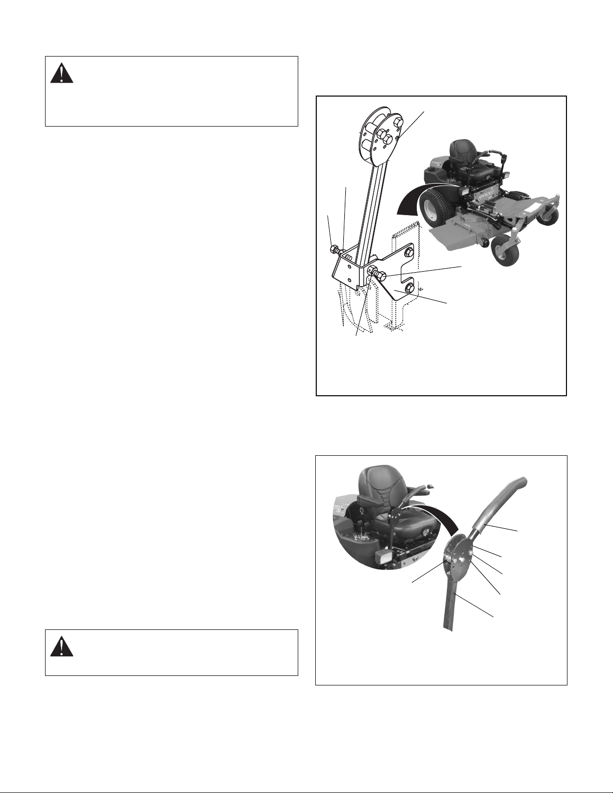
problem, adjust the limiter bolts on the stop bracket
(Figure 12). Front bolts adjust forward and rear bolts
adjust reverse. Lengthen the limiter bolt (move closer to
lever) on side which is too fast.
3
2
1
1
4
OF3577
2
1. Limiter Bolt
2. Jam Nut
3. Steering Lever
4. Stop Bracket
Figure 12
ADJUSTING THE HEIGHT OF THE
STEERING LEVER HANDLES
The handles have three height positions (Figure 13).
2
Position # 1
Position # 2
1
1. Eccentric
Spacer
2. Handle
3. Steering Lever
Figure 13
1. Shut OFF engine. Engage parking brake. Remove
the ignition key.
Position # 3
3
OF3570
GB - 21
Page 22
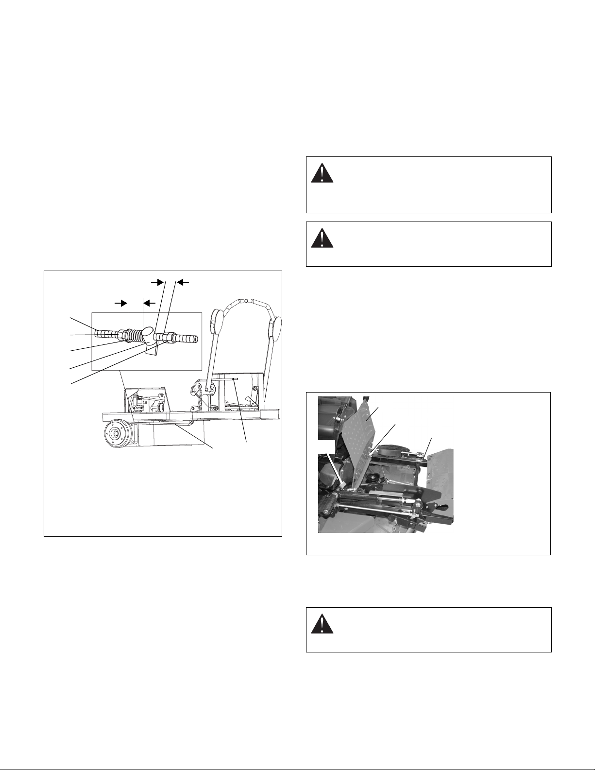
2. Remove the spacer, handle, and eccentric spacers
from the steering lever.
NOTE: Position the right and left handles at the same
height position.
3. Install the eccentric spacers, spacers and handle in
the appropriate height position. Do not tighten the
nuts holding the eccentric spacers.
4. Turn the eccentric spacer until the right and left
handles are the same height. Tighten nut.
ADJUSTING THE PARKING BRAKE
The parking brake might need adjustment over time and
after new brake pads have been installed.
NOTE: After installing new brake pads in the calipers,
they must be burnished by driving for a short distance
(about 100 feet) with the brake on. To do this, bring the
parking brake lever part-way up while driving in a straight
line. This quickly breaks-in the pads for maximum effectiveness.
is 1-1/2" (3.81 cm) clearance between the jam nuts
and trunnion.
3. Ti ghten jam nuts together.
4. Turn the return nuts clockwise to decrease the
distance or counterclockwise to increase the
distance until there is 1/16 to 1/8" (1.59 to 3.18 mm)
between the return nuts and trunnion.
5. Tighten return nuts together.
BELTS
WARNING: MOVING PARTS can cut or
amputate body parts. ALWAYS wait for moving
parts to stop before performing maintenance or
service.
CAUTION: DAMAGED OR WORN BELTS may
result in injury and/or damage to unit. Check
belts for excessive wear or cracks often.
1-1/2"
(3.81 cm)
1/16 to 1/8" (1.59
to 3.18 mm)
2
6
5
4
3
12
1. Parking Brake Lever
2. Brake Rod
3. Return Nuts
Figure 14
4. Trunnion
5. Spring
6. Jam Nuts
OF3303
Check Adjustment
NOTE: Be sure to check the parking brake on both sides
of the unit (Figure 14).
With the parking brake engaged, the spring length should
measure 1 1/2" between the jam nuts and the trunnion
and the clearance between the return nuts and trunnion
should measure 1/16 to 1/8" (1.59 to 3.18 mm). If either
of these measurements is off, adjust the parking brake
appropriately.
Belt Access
1. Properly stop and park unit (refer to Operation
Section).
2. Lower the mower.
3. Place seat in most rearward position.
4. Remove belt covers.
5. Place foot board in open position (Figure 15).
6. Secure raised footboard with latch.
1
2
3
4
Figure 15
1. Footboard in
open position
2. Pivot
3. Support
Frame
4. Latch
OF3580
Replacing Mower Belts
NOTE: Long mower belt must be removed to remove
short mower belt.
CAUTION: Use care when releasing idler spring
tension. Keep body parts well away from idlers
when performing this operation .
Adjust the Parking Brake
1. Engage the parking brake.
2. Turn the jam nuts clockwise to compress the spring
or counterclockwise to extend the spring until there
1. Slowly release the tension on the long mower belt
idler until all the tension is removed from the
springs.
GB - 22
Page 23
2. Remove long mower belt from left blade spindle
"
t
and remove from deck.
3. Slowly release the tension on the short belt idler
until all the tension is removed from the springs.
4. Remove short mower belt from right blade spindle
and from deck. Idler pivot bolt must be loosened
slightly to gain clearance to remove belt from under
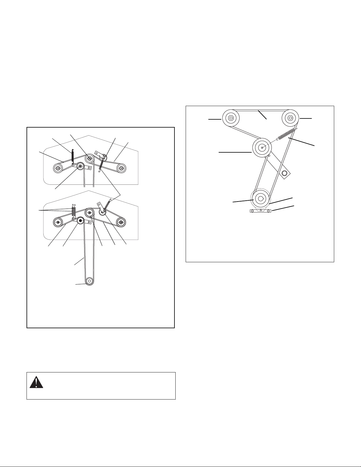
idler pulley (Figure 16).
5. Arrange new mower belt(s) on deck (short belt
first). Retighten short mower belt idler pivot bolt.
Install belts on sheaves. Put belts onto center
sheave last.
6. Replace belt covers and return foot board to closed
position.
2
3
4
5
1
72" Belt
Layout
4. Slowly release the tension on the hydro pump belt
idler until all the tension is removed from the
springs.
5. Remove old hydro pump belt from right hand
hydrostat sheave first (Figure 17).
6. Install new hydro pump belt by positioning belt on
sheaves. Put belt onto right hand hydrostat sheave
last.
7. Replace clutch anchor.
8. Replace long mower belt on mower clutch sheave.
See Replacing Mower Belts on page 22.
1
2
3
4
8
7
2
2
52" and 60
Belt Layou
1
7
1
6
3
1. Long Mower Belt
2. Springs
3. Center Sheave
4. Short Mower Belt Idler
5. Short Mower Belt
6. Mower Clutch Sheave
7. Long Mower Belt Idler
Figure 16
4
5
OF1641
Replacing the Hydro Pump Belt
1. Properly stop and park unit (refer to Operation
Section).
2. Remove the long mowe r belt from the m ower clutch
sheave. See Replacing Mower Belts on page 22.
7
1. Right Hand Hydrostat
2. Hydro Belt
3. Left Hand Hydrostat
4. Spring
5. Clutch
6. Clutch Anch or
7. Engine Sheave
8. Idler
5
6
Figure 17
MOWER DECKS
Adjusting Anti-Scalp Rollers
The anti-scalp rollers are set at the factory for typical
mowing height, but can be adjusted for high or low
cutting conditions (Figure 18).
Rollers are intended to prevent lawn scalping, not to
control cutting height.
For a very high cutting height, set the rollers in their
lowest position on the bracket.
For a very low cutting height, set the rollers in their
highest position on the bracket.
All rollers should be set at the same height.
OF1631
CAUTION: Use care when releasing idler spring
tension. Keep body parts well away from idlers
when performing this operation.
3. Remove clutch anchor.
GB - 23
Page 24
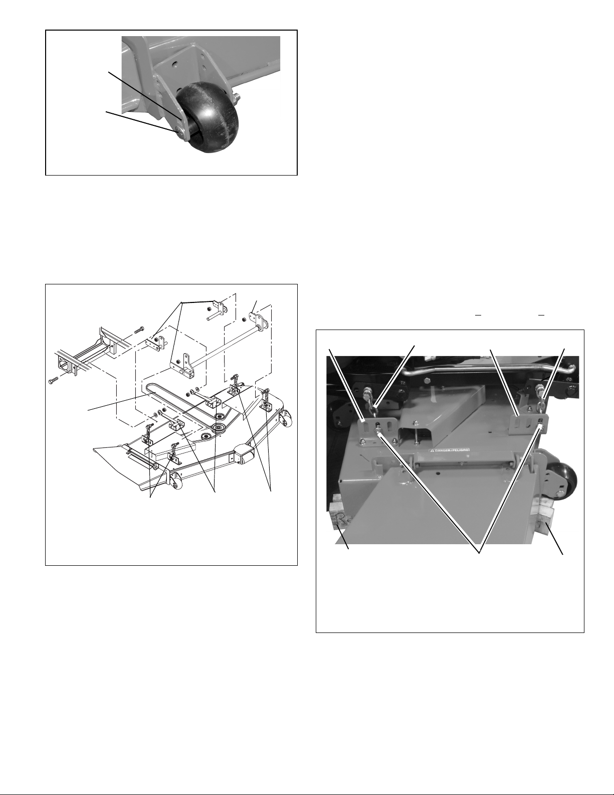
Lowest
Cutting
Height
Highest
Cutting
Height
Figure 18
Removing the Mower Deck
1. Remove PTO (long) mower belt. See Replacing
Mower Belts on page 22.
2. Remove link chains from mower lif t arms . Not e hole
location on mower lift arms for replacement.
3. Remove mower mounting arms from frame.
4. Slide mower deck out from under unit.
1
1
OF3590
Level the mower with the slots where 4 chains fasten to
the mower mounting brackets (Figure 20).
1. Shut off engine. Engage parking brake. Remove
the ignition key.
2. Raise mower deck to its highest position and place
4.75 in. (12.1 cm) tall blocks at each rear corner
and 4.625 in. (11.7 cm) tall blocks at each front
corner.
3. Lower deck onto the blocks.
4. Loosen the locknuts on the side where the chains
are slack and slide the bolt down the slot until the
chains are tight.
5. Ti ghten the locknuts.
6. Lift mower and remove blocks.
7. Measure height of deck at each side.
Measurements must be within 3/16 in. (4.76 mm) of
each other.
8. If measurements are out of range, fix by adjusting
chains on low side of deck.
9. Once deck is level side to side, measure height of
deck at middle of front and on both sides of rear.
Front of deck should be 1/8 in. +
1/8 in. (3.18 + 3.18
mm) lower than rear.
3
1
3
1
4
2
Of0316
1. Mower Lift Arm
2. Link Chain
2
Figure 19
3
3. Mower Mounting Arm
4. PTO (Long) Mower
Belt
Installing the Mower Deck
1. Slide mower deck under unit.
2. Install mower mounting arms on frame.
3. Install link chains on the mower lift arms in the
same holes they were removed from.
4. Install PTO (long) mower belt. See Replacing
Mower Belts on page 22.
5. Level mower deck.
Leveling the Mower Deck
These adjustments should be made on a level surface
with the tires inflated to the correct air pressure.
5
1. Chains
2. Lock Nuts and Slots
3. Mower Mounting
Brackets
Figure 20
2
4. 4.675 in. (11.7 cm)
Blocks
5. 4.75 in. (12 cm) Blocks
4
OF3760
GB - 24
Page 25

LONG TERM
STORAGE
WARNING: AVOID INJURY. Read and
understand entire Safety section before
proceeding.
SHORT TERM
NEVER spray unit with high pressure water or store unit
outdoors.
Inspect unit for visible signs of wear, breakage or
damage.
Keep all nuts, bolts and screws properly tightened and
know unit is in safe working condition.
Store unit in a cool, dry protected area.
Clean unit thoroughly with mild soap and low pressure
water and lubricate (See Lubricate Unit on page 20 in
Maintenance). Touch up all scratched painted surfaces.
Remove weight from wheels by putting blocks under
frame or axle.
When storing unit for extended periods of time, remove
all fuel from tank and carburetor (run dry). Refer to
Engine Manual.
Clean and charge the battery . Charge battery every three
to four weeks when storing unit.
To Take the Unit Out of Storage
1. Refer to the engine service manual to prepare the
engine for service.
2. Put fresh, clean fuel in the fuel tank.
3. Begin the maintenance schedule.
4. Charge and install the battery.
TROUBLESHOOTING
PROBLEM PROBABLE CAUSE CORRECTION
Engine does not
crank.
Engine cranks but
does not start.
Battery light does not
light up when starting
engine.
Oil pressure light is
on.
1. PTO engaged.
2. Parking brake disengaged.
3. Loose or corroded battery cables.
4. Discharged battery.
5. Faulty starter.
1. Fuel tank empty.
2. Faulty spark plug.
3. Air cleaner is plugged or dirty.
4. Fuel filter is dirty.
5. Faulty engine.
1. Discharged battery. 1. Charge battery (see Battery on page 19).
1. Oil pressure is low. 1. Refer to Engine Manual.
1. Disengage PTO.
2. Engage parking brake.
3. Clean and tighten battery cables (see
Battery on page 19).
4. Charge battery (see Battery on page 19).
5. See your Gravely Dealer.
1. Fill fuel tank (see Filling Fuel Tank on
page 13).
2. Replace spark plug. Refer to Engine
Manual.
3. Clean or replace air cleaner. Refer to
Engine Manual.
4. Clean or replace fuel filter. Refer to
Engine Manual.
5. Refer to Engine Manual or see your
Gravely Dealer.
Engine continues to
run when ignition key
is in the off position.
1. Ignition ground wire disconnected.
2. Ignition switch failure.
GB - 25
1. Connect ground wire to clean metal
surface.
2. Replace ignition switch (see your Gravely
Dealer).
Page 26
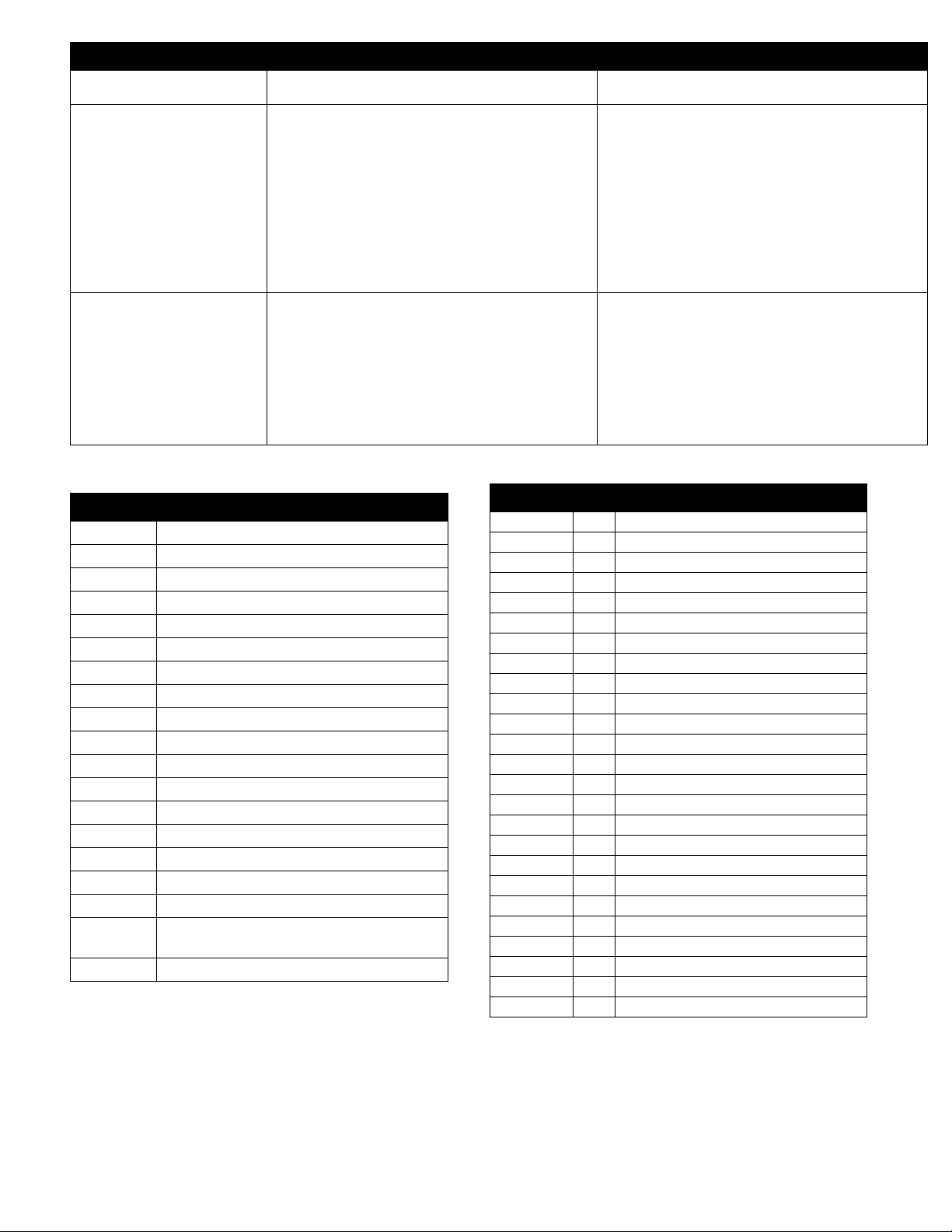
TROUBLESHOOTING
PROBLEM PROBABLE CAUSE CORRECTION
PTO or mower blades
1. Operator presence switch not depressed.
do not engage or
shuts off.
Unit does not drive.
2. Eye-Q
3. The Eye-Q
4. Faulty PTO switch.
1. Parking brake engaged.
2. Transmission bypass levers open.
3. Hydraulic oil level low.
4. Faulty hydraulic drive system.
TM
alarm setting is turned on.
TM
circuitry senses an
overload to the PTO clutch and is
shutting off the PTO switch.
ACCESSORIES
Part No. Description
78803500 52" Mul ch ing Kit
78803900 52" Bahia/Tall Grass Baffle Kit
79200300 60" Mul ch ing Kit
79200400 Discharge Cover Kit - 60" Decks
79200900 72" Mul ch ing Kit
79201000 Discharge Cover Kit - 72" Decks
79201600 60" Bahia/Tall Grass Baffle Kit
79201700 Counte rweig ht Kit
79202000 72" Bahia/Tall Grass Baffle Kit
79202100 Lif tm ast er Kit
79202300 Hitch Kit
79202400 Antisca lp Whe el Kit
79202600 Lawn Striper Kit, 60" and 72"
79202800 Discharge Cover Kit - 52" Decks
79203100 Lawn Striper Kit, 52"
89200100 Rollover Protection System (ROPS)
89200200 60" Bagger (Peco) (requires bumper p/n
09249953)
89200500 60" Bagg er
1. Depress operator presence switch by
sitting on seat.
2. Turn off the alarm that deactivates the
PTO on a regular schedule. See Eye-Q
Owner’s Manual.
3. Check the mower deck for cloggi ng or
debris. Check the electrical system to the
clutch for damage or wear.
4. See your Gravely Dealer.
1. Disengage parking brake.
2. Close transmission bypass levers (see
Moving the Unit with the Engine Off on
page 14).
3. Add hydraulic oil (see Hydraulic Fluid on
page 17).
4. See your Gravely dealer.
SERVICE PARTS
Part No. Qty Description
01554800 1 Battery
21539600 1 Air Filter Outer Element - Kawasaki
21539700 1 Air Filter Inner Element - Kawasaki
21537000 1 Outer Primary Element - Kohler
21536900 1 Inner Safety Element - Kohler
21536300 1 Element Precleaner - Kohler 25 HP
21535800 1 Engine Oil Filter - Kawasaki
21397200 1 Engine Oil Filter - Kohler
09246900 1 Hydraulic Oil Filter
21536100 2 Spark Plug - Kawasaki
21525900 2 Spark Plug - Kohler
07240700 1 PTO (Engine to Deck) Belt (52")
07241300 1 PTO (Engine to Deck) Belt (60")
07242300 1 PTO (Engine to Deck) Belt (72")
07222300 1 Mower Drive Belt (52")
07235000 1 Mower Drive Belt (60")
07237700 1 Mower Drive Belt (72")
07242000 1 Traction (Hydro Pump) Belt - Poly V
04916400 1 Blade (52")
04917900 1 Mulch Blade (52")
09081200 1 Blade (60")
08866900 1 Mulch Blade (60")
09290500 1 Blade (72")
09290600 1 Mulch Blade (72")
GB - 26
Page 27

SPECIFICATIONS
Model Number 992066 992067 992068 992069 992070 992071 992072
Model 252Z 260Z 260Z 260Z 272Z 252Z 272Z
Length – cm (in) 203 (80)
Height – cm (in) 127 (50)
Width – cm (in) 165 (65) 185 (73) 216 (85) 165 (65) 216 (85)
Weight Actual – kg (lbs ) 476.2 (1050) 510.2 (1125) 532.9 (1175) 476.2 (1050) 532.9 (1175)
Battery 12 volt
Brakes Hydro/Dynamic Drum– Parking
Turning Radius 0
Tire Size Front
Engine – manufacturer Kawasaki Kawasaki Kohler Kohler EFI Kawasaki Kohler
Model Number FH721V CV740S CV74SS FH721V CV740S
Cycle 4
Engine Power – HP
(kW) @ Governed RPM
Governed RPM 3600
Idle RPM 1800
Starting System Electric
Fuel Tank Capacity 14 gals. US (53 liters)
Fuel See Engine Manual
Air Cleaner Heavy Duty Dual Element with Pre-Clean Screen
Cooling Capacity A ir Cooled
Engine oil type See Engine Manual
Spark Plug Gap See Engine Manual
Transmission Hydrostatic Drive
Speed – Forward Max.
Reverse Max.
Transmission Lube Mobil 1 15W-50 Synthetic
Drive Clutch Hydrostatic
Tire Pressure Front
Lift System Hydraulic
Power Take Off Electric PTO Clutch/Brake
Cutting Width – cm (in) 132 (52) 152 (60) 183 (72) 132 (52) 183 (72)
Cutting Height – cm (in) 2.5 - 12.7 (1 - 5)
Cut Increments – cm (in) Infinite between 2.5 -12.7 (1 - 5)
Max. Towing Capacity –
kg (lbs)
Max. Tongue Weight –
kg (lbs)
Rear
Rear
25 (18.6) 27 (20.1) 28 (20.9) 25 (18.6) 27 (20.1)
20-25 psi (138-172 kN/m
15 x 6 - 6
24 x 12 - 12
13 MPH (20.8 KM/H)
6 MPH (9.6 KM/H)
12-15 psi (83-103 kN/m
226.8 (500)
22.7 (50)
2
)
2
)
GB - 27
Page 28

2-Year Limited Warranty
Gravely Division of Ariens Company (Gravely) hereby warrants to the
Gravely Division of Ariens Company
655 West Ryan Street
P.O. Box 157
Brillion, WI 54110-0157
920-756-2141
Fax 920-756-2407
www.gravely.com
This warranty is subject to the following exceptions, conditions, and limitations:
Usage Requirement
The duration of this warranty shall be ninety days or 1000 hours, whichever comes first, if the product is rented or leased.
original consumer purchaser that all Gravely Two-Wheel,
Professional G, Pro, and ProMaster products will be free from defects
in material and workmanship for a period of two (2) years from the date
of purchase or 1000 hours, whichever comes first.
Protection Plan
Gravely will repair or replace any part found upon examination by
Gravely to be defective. Such repair or replacement will be free of
charge to the purchaser (labor and parts), except as noted below.
Purchasers Responsibilities
The purchaser must perform maintenance and minor
adjustments per the operators manual.
The purchaser must notify Gravely or an authorized Gravely
service representative of the need for warranty service.
The purchaser must transport the product to and from the place
of warranty repair.
Product Registration
Returning the product registration card to Gravely will enable
the company to contact the registrant with repair or replacement
part information.
Service Parts and Accessories
Service parts and accessories not purchased with the product
covered by this warranty are warranted to be free of defects
for a period of ninety (90) days following the date of purchase,
and will be replaced free of charge (except for labor).
Service
Warranty service must be done by an authorized Gravely dealer.
To find an authorized Gravely service representative, contact
Gravely at the website, number or address above.
Battery Warranty Prorated
One to three months - Free replacement
Four to twelve months - Prorated over 12 months
Gravely may from time to time change the design of its products. Nothing contained in this warranty shall be construed as obligating
Gravely to incorporate such design changes into previously manufactured products, nor shall such changes be construed as an admission
that previous designs were defective.
Exclusions (No Warranty)
Normal maintenance, services, and normal replacement items,
such as spark plugs, oil, oil filters, air filters, mufflers, belts,
tires, shoes, runners, scraper blades, shear bolts, mower blades,
mower vanes, headlights, light bulbs, knives, etc. are not covered
by this warranty.
Any equipment which has been altered, misused, misassembled,
improperly adjusted, neglected, or damaged by accident is not
covered by this warranty.
Service completed by someone other than an authorized
Gravely dealer is not covered by this warranty.
Any attachment not approved by Gravely nor any parts that
are not genuine Gravely service parts are not covered by this
warranty.
Engines and engine accessories are covered only by the
warranty made by the engine manufacturer, and are not covered
by this warranty.
If the product is equipped with a Hydro-Gear transmission
and/or Hydro-Gear drive components, the Hydro-Gear
transmission and/or drive components are covered only by the
warranty made by Hydro-Gear, and are not covered by this
warranty.
This warranty applies only to products purchased in the United
States (including Puerto Rico) and Canada. In all other
countries, contact place of purchase.
LIMITATION OF REMEDY AND DAMAGES
Gravelys liability under this express warranty, and under any implied
warranty that may exist, is limited to repair or replacement of any
defective part. In no event shall Gravely be liable for incidental,
special, or consequential damages (including lost profits). This
warranty gives you specific legal rights. You may also have other
rights which vary from state to state. Some states do not allow the
exclusion of incidental or consequential damages, or limitations on
how long an implied warranty lasts, so the above limitations and
exclusions may not apply to you.
GB - 28
DISCLAIMER OF FURTHER WARRANTY
Gravely makes no warranty other than what is
expressly made in this warranty. If the law of your
state provides that an implied warranty of
merchantability, or an implied warranty of fitness
for a particular purpose, applies to Gravely, any
such implied warranty is limited to the duration of
this express warranty.
Form: GLW2-122002
Page 29

GRAVELY
A Division of Ariens Company
655 West Ryan Street
P.O. Box 157
Brillion, WI 54110-0157
920-756-2141
Fax 920-756-2407
www.gravely.com
 Loading...