

Gravely 985112, 985111, 985103, 985113, 985104 User Manual
...
Professional 2-Wheel Tractor
Service Manual
Models 985103,104, 105, 107 - 115, 117
08483800 08/00
Printed in USA

TABLE OF CONTENTS
Section 1 - Introduction. . . . . . . . . . . . . . . . . . . 1-3
1.1 The Manual. . . . . . . . . . . . . . . . . . . . . . . . . 1-3
1.2 Service And Replacement Parts. . . . . . . . . 1-3
1.3 Product Registration . . . . . . . . . . . . . . . . . . 1-3
1.4 Unauthorized Replacement Parts. . . . . . . . 1-3
1.5 Disclaimer. . . . . . . . . . . . . . . . . . . . . . . . . . 1-3
1.6 Technical Service Communications . . . . . . 1-3
1.7 Preparation . . . . . . . . . . . . . . . . . . . . . . . . . 1-4
Section 2 - Safety. . . . . . . . . . . . . . . . . . . . . . . . 2-4
2.1 Safety Alerts . . . . . . . . . . . . . . . . . . . . . . . . 2-4
2.2 Signal Words. . . . . . . . . . . . . . . . . . . . . . . . 2-4
2.3 Notations. . . . . . . . . . . . . . . . . . . . . . . . . . . 2-4
2.4 Practices And Laws . . . . . . . . . . . . . . . . . . 2-4
2.5 Maintenance And Storage . . . . . . . . . . . . . 2-4
2.6 Safety Rules . . . . . . . . . . . . . . . . . . . . . . . . 2-4
2.7 Training. . . . . . . . . . . . . . . . . . . . . . . . . . . . 2-4
2.8 Preparation . . . . . . . . . . . . . . . . . . . . . . . . . 2-5
2.9 Operation . . . . . . . . . . . . . . . . . . . . . . . . . . 2-5
Section 3 - Specifications . . . . . . . . . . . . . . . . . 3-6
Section 4 - General Maintenance
& Adjustments. . . . . . . . . . . . . . . . . . . . . . 4-10
4.1 Controls And Features . . . . . . . . . . . . . . . 4-10
4.2 Filling The Fuel Tank. . . . . . . . . . . . . . . . . 4-10
4.3 General Lubrication . . . . . . . . . . . . . . . . . 4-11
4.4 Forward-Reverse Clutch Adjustment . . . . 4-11
4.5 Hi/Low Gear Clutch Adjustment . . . . . . . . 4-12
4.6 Steering Brake Adjustment
(Applicable Models) . . . . . . . . . . . . . . . . . 4-12
4.7 PTO Brake Adjustment . . . . . . . . . . . . . . . 4-13
4.8 Slip Clutch Adjustment . . . . . . . . . . . . . . . 4-14
Section 5 - Engine . . . . . . . . . . . . . . . . . . . . . . 5-15
5.1 Engine Troubleshooting . . . . . . . . . . . . . . 5-15
5.2 Checking Engine Oil . . . . . . . . . . . . . . . . . 5-16
5.3 Changing Oil. . . . . . . . . . . . . . . . . . . . . . . 5-16
5.4 Air Cleaner . . . . . . . . . . . . . . . . . . . . . . . . 5-16
5.5 Engine Removal And Installation . . . . . . . 5-17
5.6 Engine Maintenance. . . . . . . . . . . . . . . . . 5-17
5.7 Engine Storage. . . . . . . . . . . . . . . . . . . . . 5-17
Section 6 - Steering & Controls . . . . . . . . . . . 6-18
6.1 Handlebar Assembly. . . . . . . . . . . . . . . . . 6-18
6.2 Steering Brakes (Optional) . . . . . . . . . . . . 6-19
6.3 Adjusting Brakes. . . . . . . . . . . . . . . . . . . . 6-19
6.4 Power Take Off Control. . . . . . . . . . . . . . . 6-22
6.5 Range Shift Control (Two Speed Axle) . . . 6-22
Section 7 - Drive Train . . . . . . . . . . . . . . . . . . . 7-23
7.1 Transmission Trouble Analysis . . . . . . . . . 7-23
7.2 Clutch Adjustment. . . . . . . . . . . . . . . . . . . 7-24
7.3 Transmission Removal . . . . . . . . . . . . . . . 7-24
7.4 Forward-Reverse Clutch &
Planetary System . . . . . . . . . . . . . . . . . . . 7-24
7.5 First -Second Gear, Clutch And Planetary 7-24
7.6 Differential. . . . . . . . . . . . . . . . . . . . . . . . . 7-25
7.7 Differential Removal . . . . . . . . . . . . . . . . . 7-25
7.8 Power Take Off (PTO). . . . . . . . . . . . . . . . 7-28
Section 8 - Fuel System. . . . . . . . . . . . . . . . . . 8-29
8.1 Fuel System Troubleshooting . . . . . . . . . . 8-29
8.2 Fuel Pump . . . . . . . . . . . . . . . . . . . . . . . . 8-30
8.3 Fuel System Contamination . . . . . . . . . . . 8-30
8.4 Fuel Tank . . . . . . . . . . . . . . . . . . . . . . . . . 8-30
Section 9 - Electrical . . . . . . . . . . . . . . . . . . . . 9-31
9.1 Tools . . . . . . . . . . . . . . . . . . . . . . . . . . . . . 9-31
9.2 Electrical Measurements. . . . . . . . . . . . . . 9-31
9.3 Safety Interlock System . . . . . . . . . . . . . . 9-32
9.4 Battery . . . . . . . . . . . . . . . . . . . . . . . . . . . 9-32
9.5 Switches . . . . . . . . . . . . . . . . . . . . . . . . . . 9-35
9.6 Solenoid And Relays. . . . . . . . . . . . . . . . . 9-35
9.7 Fuses . . . . . . . . . . . . . . . . . . . . . . . . . . . . 9-36
9.8 Diodes And Rectifiers . . . . . . . . . . . . . . . . 9-36
9.9 Wiring Diagram . . . . . . . . . . . . . . . . . . . . . 9-37
9.10 Continuity Diagram . . . . . . . . . . . . . . . . . 9-38
9.11 12 HP Electric Start - Kohler . . . . . . . . . . 9-39
9.12 8 HP Manual Start - Kohler. . . . . . . . . . . 9-40
9.13 8 HP Electric Start - Kohler. . . . . . . . . . . 9-41
9.14 16 HP Electric Start - Briggs. . . . . . . . . . 9-42
9.15 Robin Engines . . . . . . . . . . . . . . . . . . . . 9-43
2

SECTION 1 - INTRODUCTION
1.1 THE MANUAL
The purpose of this manual is to provide complete
instructions for service, maintenance, disassembly,
repair, and installation of the mechanical components
for the unit.
Dealer trained service personnel should use this
manual as a supplement to and reminder of the training
sessions conducted by the company.
Read all information for servicing a part or system
before repair work is started to avoid needless
disassembly.
Operation
Before operation of the unit, carefully and completely
read manuals supplied with the unit. The contents will
provide you with an understanding of safety
instructions and controls during normal operation and
maintenance.
Safety Messages
For your safety and the safety of others always read,
understand, and follow all DANGER, WARNING, and
CAUTION messages found in manuals and on safety
decals.
Directional Reference
All reference to left, right, front, or rear are given from
the operator in the operator position and facing the
direction of forward travel.
1.2 SERVICE AND REPLACEMENT PARTS
When ordering publications, replacement parts, or
making service inquiries, know the Model and Serial
numbers of your unit and engine.
Numbers are located on the product registration form in
the unit literature package. They are printed on a serial
number label, located under the hood of your unit.
1.3 PRODUCT REGISTRATION
A warranty registration card must be filled out, signed,
and returned at time of purchase. This card activates
the warranty. Claims meeting requirements during
limited warranty period will be honored.
Specific Model and Serial Numb er s are on a label
located on the frame of your Tractor and on a label
located on the product registration form. Record those
numbers below and transfer the label from the product
registration to place indicated be low. Use these
numbers whenever parts or service is required.
1.4 UNAUTHORIZED REPLACEMENT
PARTS
Use only Gravely replacement parts. The replacement
of any part on this vehicle with anything other than a
Gravely authorized replacement part may adversely
affect the performance, durability, or safety of this unit
and may void the warranty. Gravely disclaims liability
for any claims or damages, whether warranty, property
damage, personal injury, or death arising out of the use
of unauthorized replacement parts.
1.5 DISCLAIMER
Gravely reserves the right to discontinue, make
changes to, and add improvements upon its products
at any time without public notice or obligation. The
descriptions and specifications contained in this
manual were in effect at printing. Equipment described
within this manual may be optional. Some illustrations
may not be applicable to your unit.
1.6 TECHNICAL SERVICE
COMMUNICATIONS
Gravely Technical Service communicates information
to the field using Service Letters, Service Bulletins,
Product Notices, and Campaigns. Each
communication signifies a type of information and
priority. The dealer is responsible to carry out the
directive provided in the communication. The types of
communication are:
Service Letter
dealer. Technical information on how to service the
product and product improvements.
Service Bulletin
resolve certain issues or a notification of a policy
change.
Product Notices
located in a certain region. This is a limited distribution
to only those who received the product involved.
Campaigns
products must be updated and are tracked by the
factory until all units are corrected.
- General technical information for the
- Notification to update products to
- Notification of limited product
- Notification of a safety related issue. All
1 -3

1.7 PREPARATION
Before starting any removal of parts, proper
preparation is very important for efficient work. A clean
work area at the start of each job will allow you to
perform service repairs easily and quickly.
To reduce the incidence of misplaced tools or parts,
place removed components with all attaching hardware
SECTION 2 - SAFETY
in the disassembly order on a clean work surface.
Organization is a key part of proper reassembly.
T ools, instruments, and parts needed for the job should
be gathered before work is started. Interrupting a job to
locate tools or parts is a needless delay.
2.1 SAFETY ALERTS
Look for these symbols to point out
important safety precautions. They
mean:
Attention!
Personal Safety Is Involved!
Become Alert!
Obey The Message!
2.2 SIGNAL WORDS
The safety alert symbol is used in decals on the unit
and with proper operation procedures in this manual.
They alert you to the existence and relative degree of
hazards.
Understand the safety message. It contains important
information about personal safety on or near the unit.
DANGER:
SITUA TION! If not avoided, WILL RESULT in
death or serious injury.
WARNING:
SITUA TION! If not avoided, COULD RESULT
in death or serious injury.
CAUTION:
SITUA TION! If not avoided, MAY RESULT in
minor or moderate injury. It may also be used
to alert against unsafe practices.
IMMINENTLY HAZARDOUS
POTENTIALLY HAZARDOUS
POTENTIALLY HAZARDOUS
2.3 NOTATIONS
NOTE:
ation and maintenance practices .
IMPORTANT:
required to prevent damage to unit or attachment.
General reference information for proper oper-
Specific procedures or information
2.4 PRACTICES AND LAWS
Practice usual and customary safe working
precautions, for the benefit of yourself and others.
Understand and follow all safety messages. Be alert to
unsafe conditions and the possibility of minor,
moderate, or serious injury or death. Learn applicable
rules and laws in your area.
2.5 MAINTENANCE AND STORAGE
Keep the equipment in good condition. Maintain it as
directed in this manual. Check all hardware at regular
intervals.
Use only Gravely accessories, attachment and
replacement parts.
Do not overspeed the engine. Do not ov erride the
governor.
Before making any repairs, adjustments inspections or
cleaning unit disengage the PTO, turn off and remove
the ignition key and wait for all motion to stop.
To reduce fire hazard and overheating, keep
equipment free of grass, leaves, debris or excessive
lubricants.
Worn out mufflers can result in fire or explosion and
should be replaced immediately.
Never store equipment with gasoline in tank inside a
building where fumes may reach an open flame or
spark. Allow engine to cool before storing in any
enclosure.
2.6 SAFETY RULES
Improper use of this tractor can injure people and
damage the equipment. People using or servicing this
tractor must read and follow the instructions in this
manual.
It is important to understand that this manual and any
other Gravely instruction manuals do not cover every
possible danger. It is impossible for Gravely to know of
all possible dangers in operating and servicing the
tractor and attachments.
The purchaser must give these instructions to the
people operating and maintaining this tractor. These
people must use eye and foot protection.
2.7 TRAINING
Read this manual, the attachment manual and the
engine manual carefully before operating unit.
2 -4

Learn the location and function of all controls.
Learn how to use the controls to stop the wheels and
attachment quickly in an emergency.
Understand and follow each danger, warning, caution
and instruction decal installed on this product.
Never permit children to operate the Two-Wheel
Tractor . Do not allow adults to operate it without proper
instruction. Safe operation of this equipment requires
your complete and unimpaired attention at all times. Do
not operate unit after or during the consumption of
drugs or alcohol.
Keep all people and animals away from the operating
area.
2.8 PREPARATION
Use caution with gasoline. Gasoline is very flammable
and its vapors are explosive. Keep it in a clean, tight
and approved (Red) container. Never put gasoline in
the fuel tank while the engine is running or hot. Clean
up spilled gasoline before starting engine. Do not fill
fuel tank indoors. Never allow smoking materials,
sparks or flame (match, pilot light, etc.) near mower or
fuel container. Replace fuel tank cap and fuel container
cap securely.
Inspect area of operation and remove all material
which could be thrown by the attachment such as
stones, sticks, wires and other foreign objects.
When hauling the equipment, connect the chassis to
the transporting vehicle. Never connect from control
levers, rods, or like items that could be damaged.
Replace all parts that become damaged or lost.
Wear hand, foot, head, ear and eye protection. Do not
wear loose clothing, which might get caught in rotating
parts of the unit.
Before making adjustments, cleaning, removing
obstructions or servicing the tractor or attachment
move the PTO to "OFF", turn the ignition switch to
"OFF", remove the ignition key and wait until all moving
parts completely stop.
WARNING:
that jack stands or blocks used are stable,
strong, or secure and will hold the weight of
the unit during maintenance.
Always block wheels and know
only if at least one of the operator presence switches is
depressed.
Do not use the equipment in the dark without adequate
lighting.
Keep away from moving parts. Stay clear of the
attachment whenever the engine is running.
Do not let people other than the operator near the
operating equipment. Never direct disengage the
attachment drive when moving the tractor to and from
work areas.
Use a slow speed and engage the shift lever slowly
when operating on slopes.
Travel across slopes, not up and down. Use extreme
caution when changing direction on slopes. Do not
operate on steep slopes.
Look for and keep away from hazards, such as
dropoffs. Stay alert for holes, rocks and other hidden
hazards in the area of operation.
After hitting an object, disengage the PTO, turn off and
remove the ignition key and wait for all motion to stop.
Check for damage. Repair any damage before
restarting unit.
Look behind when operating in reverse. Look for
people and hazards.
Operate only from the operator’s position, just behind
the handlebars.
If there is a sudden change in the sound or vibration of
the equipment, disengage the PTO, turn off and
remove the ignition key, wait for all motion to stop and
check for damage. Repair any damage or failure before
restarting unit.
Never run the engine indoors except to move it outside.
Exhaust fumes are dangerous.
Go slowly on slick surfaces. Always be sure of your
footing, keep a firm grip on the handlebars and walk,
never run.
Follow traffic laws when operating on or near a road.
Before leaving the operator’s position, put the PTO
lever in the "OFF" position, turn off and remove ignition
key. Move the shift control to first gear position.
Do not touch parts which might be hot from operation.
Before attempting to maintain, adjust or service allow
such parts to cool.
2.9 OPERATION
Be certain that all shields, guards, and interlock
switches are in the correct position and operating
properly.
Before starting the engine, put the PTO lever in the
"OFF" position and the gear shift lever in the neutral
"N" position.
Check the operation of the operator presence controls
before operating the tractor. With either the PTO or the
direction control lever engaged, the engine should run
2 -5

SECTION 3 - SPECIFICATIONS
Model Number 985103 985104 985105 985107
Description 8HP Gear Drive 8HP Gear Drive 8HP Gear Drive 12 HP Gear Drive
Brakes Optional, individual, 7" (17.8 cm) x 1.75" (4.4 cm) drum type
Steering Manual, optional power steering kit available
Turning Radius Zero (with steering kit)
Minimum Uncut Circle Zero Zero Zero Zero
Optional Tire Sizes
-Stud Tread 4" x 8", 4 ply 4" x 8", 4 ply 4" x 8", 4 ply 4" x 8", 4 ply
-Trac Tread 4" x 8", 4 ply 4" x 8", 4 ply 4" x 8", 4 ply 4" x 8", 4 ply
-Turf-Chief 18" x 6.5" x 8", 4 ply 18" x 6.5" x 8", 4 ply 18" x 6.5" x 8", 4 ply 18" x 6.5" x 8", 4 ply
-Turf-Saver 18" x 8.5" x 8", 4 ply 18" x 8.5" x 8", 4 ply 18" x 8.5" x 8", 4 ply 18" x 8.5" x 8", 4 ply
-Semi-Pneumatic 16" x 5" x 3", 4 ply 16" x 5" x 3", 4 ply 16" x 5" x 3", 4 ply 16" x 5" x 3", 4 ply
Tire Pressure 18 psi 18 psi 18 psi 18 psi
Battery 12 volt, BCI group 12 volt, BCI group 12 volt, BCI group 12 volt, BCI group
Engine Kohler Kohler Kohler Kohler
-Type K181T K181T K181S M12T (PS471525)
-Horsepower 8HP at 3600 RPM 8HP at 3600 RPM 8HP at 3600 RPM 12HP at 3600 RPM
-Number of Cylinders One One One One
-Displacement 18 cu. in. (305.4 cc) 18 cu. in. (305.4 cc) 18 cu. in. (305.4 cc) 29 cu. in. (476.5 cc)
-Fuel Gasoline, 87 minimum
octane
-Fuel Capacity 1.25 gals. (4.7 L) 1.25 gals. 4.7 L) 1.25 gals. (4.7 L) 2.0 gals. (4.7 L)
-Cooling Air Air Air Air
-Air Filter Dual Element with
PreCleaner
-Lubrication Splash System Splash System Splash System Splash System
-Oil Type See Engine Manual See Engine Manual See Engine Manual See Engine Manual
-Oil Capacity 2.5 pts. (1.2 L) 2.5 pts. (1.2 L) 2.5 pts. (1.2 L) 2.5 pts. (1.2 L)
-Oil Filter N/A N/A N/A Spin on oil filter
-Charging System Recoil Recoil 12 volt, 15 amp 12 volt, 15 amp
Transmission
-Type All gear planetary transmission with fully enclosed PTO and immersion clutch
-Oil Type SAE 30W API service class SF or higher
-Oil Capacity 5 qts (4.7 L) 5 qts (4.7 L) 5 qts (4.7 L) 5 qts (4.7 L)
-Cooling Air Air Air Air
-Number of Speeds 2 forward/2 reverse 4 forward/4 reverse 4 forward/4 reverse 4 forward/4 reverse
Speeds (with 18" tires)
-Forward 1st - 2.0 mph (3.2 kph)
2nd - 2.5 mph (4.0 kph)
-Reverse 1st - 1.9 mph (3.1 kph)
2nd - 2.4 mph (3.9 kph)
PTO
-Type Internal Slip Clutch Internal Slip Clutch Internal Slip Clutch Internal Slip Clutch
-Drive All gear shaft driven off high/low planetary
-Output Speeds High - 1179 RPM, low - 888 RPM at 3300 engine RPM
Construction Cast-iron transmission case with 7-gauge framing
Gasoline, 87 minimum
octane
Dual Element with
PreCleaner
1st - 1.3 mph (2.1 kph)
2nd - 1.7 mph (2.7 kph)
3rd - 2.6 mph (4.2 kph)
4th - 3.4 mph (5.5 kph)
1st - 1.2 mph (2.0 kph
2nd - 1.6 mph (2.6 kph)
3rd - 2.4 mph (3.9 kph)
4th - 3.1 mph (5.0 kph)
Gasoline, 87 minimum
octane
Dual Element with
PreCleaner
Gasoline, 87 minimum
octane
Dual Element with
PreCleaner
1st - 1.4 mph (2.3 kph)
2nd - 1.8 mph (2.9 kph)
3rd - 2.7 mph (4.4 kph)
4th - 3.7 mph (6.0 kph)
1st - 1.3 mph (2.1 kph)
2nd - 1.7 mph (2.7 kph)
3rd - 2.6 mph (4.2 kph)
4th - 3.3 mph (5.3 kph)
3 -6

Model Number 985108 985109 985110 985111
Description 12HP Gear Drive 16HP Gear Drive 8HP Gear Drive 8HP Gear Drive
Brakes Optional, individual, 7" (17.8 cm) x 1.75 (4.4 cm) drum type
Steering Manual, optional power steering kit available
Turning Radius Zero (with steering kit)
Minimum Uncut Circle Zero
Optional Tire Sizes
-Stud Tread 4" x 8", 4 ply 4" x 8", 4 ply 4" x 8", 4 ply 4" x 8", 4 ply
-Trac Tread 4" x 8", 4 ply 4" x 8", 4 ply 4" x 8", 4 ply 4" x 8", 4 ply
-Turf-Chief 18" x 6.5" x 8", 4 ply 18" x 6.5" x 8", 4 ply 18" x 6.5" x 8", 4 ply 18" x 6.5" x 8", 4 ply
-Turf-Saver 18" x 8.5" x 8", 4 ply 18" x 8.5" x 8", 4 ply 18" x 8.5" x 8", 4 ply 18" x 8.5" x 8", 4 ply
-Semi-Pneumatic 16" x 5" x 3", 4 ply 16" x 5" x 3", 4 ply 16" x 5" x 3", 4 ply 16" x 5" x 3", 4 ply
Tire Pressure 18 psi 18 psi 18 psi 18 psi
Battery 12 volt, BCI group 12 volt, BCI group None 12 volt, BCI group
Engine Kohler Briggs & Stratton Kohler Kohler
-Type M12S (PS471529) 303447 PS-301058 PS-30159
-Horsepower 12HP at 3600 RPM 16 HP at 3600 RPM 8 HP at 3600 RPM 8 HP at 3600 RPM
-Number of Cylinders One Two One One
-Displacement 29 cu. in. (477 cc) 29.3 cu. in. (480 cc) 18 cu. in. (305.4 cc) 18 cu. in. (305.4 cc)
-Fuel Gasoline, 87 minimum
octane
-Fuel Capacity 2.0 gals. (7.5 L) 1.5 gals. (5.7 L) 1.25 gals. (4.7 L) 1.25 gals. (4.7 L)
-Cooling Air Air Air Air
-Air Filter Dual Element with
PreCleaner
-Lubrication Splash System Full pressure pump with
-Oil Type See Engine Manual See Engine Man ual See Engine Manual See Engine Manual
-Oil Capacity 2.5 pts. (1.2 L) 3.0 pts. (1.4 L) 2.5 pts. (1.2 L) 2.5 pts. (1.2 L)
-Oil Filter Spin on oil filter Spin on oil filter Spin on oil filter Spin on oil filter
-Charging System 12 volt, 15 amp 12 volt, 16 amp Recoil 12 volt, 15 amp
Transmission
-Type All gear planetary transmission with fully enclosed PTO and immersion clutch
-Oil Type SAE 30W API service class SF or higher
-Oil Capacity 5 qts (4.7 L) 5 qts (4.7 L) 5 qts (4.7 L) 5 qts (4.7 L)
-Cooling Air Air Air Air
-Number of Speeds 2 forward/2 reverse 4 forward/4 reverse 4 forward/4 reverse 4 forward/4 reverse
Speeds
-Forward 1st - 1.4 mph (2.3 kph)
2nd - 1.8 mph (2.9 kph)
3rd - 2.7 mph (4.4 kph)
4th - 3.7 mph (6.0 kph)
-Reverse 1st - 1.3 mph (2.1 kph)
2nd - 1.7 mph (2.7 kph)
3rd - 2.6 mph (4.2 kph)
4th - 3.3 mph (5.3 kph)
PTO
-Type Internal Slip Clutch Internal Slip Clutch Internal Slip Clutch Internal Slip Clutch
-Drive All gear shaft driven off
high/low planetary
Output Speeds High - 1179 RPM, low - 888 RPM at 3300 engine RPM
Construction Cast-iron transmission case with 7-gauge framing
Gasoline, 87 minimum
octane
Dual Element with
PreCleaner
oil filter
1st - 1.4 mph (2.3 kph)
2nd - 1.8 mph (2.9 kph)
3rd - 2.7 mph (4.4 kph)
4th - 3.7 mph (6.0 kph)
1st - 1.3 mph (2.1 kph)
2nd - 1.7 mph (2.7 kph)
3rd - 2.6 mph (4.2 kph)
4th - 3.3 mph (5.3 kph)
All gear shaft driven off
high/low planetary
See Engine Manual See Engine Manual
Dual Element with
PreCleaner
Splash System Splash System
1st - 1.4 mph (2.3 kph)
2nd - 1.8 mph (2.9 kph)
3rd - 2.7 mph (4.4 kph)
4th - 3.7 mph (6.0 kph)
1st - 1.3 mph (2.1 kph)
2nd - 1.7 mph (2.7 kph)
3rd - 2.6 mph (4.2 kph)
4th - 3.3 mph (5.3 kph)
All gear shaft driven off
high/low planetary
Dual Element with
PreCleaner
1st - 1.4 mph (2.3 kph)
2nd - 1.8 mph (2.9 kph)
3rd - 2.7 mph (4.4 kph)
4th - 3.7 mph (6.0 kph)
1st - 1.3 mph (2.1 kph)
2nd - 1.7 mph (2.7 kph)
3rd - 2.6 mph (4.2 kph)
4th - 3.3 mph (5.3 kph)
All gear shaft driven off
high/low planetary
3 -7

Model Number 985112 985113 985114 985115
Description 12 HP
Gear Drive
Brakes 7 x 1.75" Drum Type N/A
Steering Manual, optional power steering kit available
Turning Radius Zero (with steering kit)
Minimum Uncut Circle Zero
Optional Tire Sizes
-Stud Tread 4.00-8 4.00-8 4.00-8 4.00-8
-Trac Tread 4.00-8 4.00-8 4.00-8 4.00-8
-Turf-Chief 18" x 6.50"-8" 18" x 6.50"-8" 18" x 6.50"-8" 18" x 6.50"-8"
-Turf-Saver 18" x 8.50"-8" 18" x 8.50"-8" 18" x 8.50"-8" 18" x 8.50"-8"
-Semi-Pneumatic N/A N/A 16" x 5" x 3" 16" x 5" x 3"
Tire Pressure 18 psi (124 Kn/m2) 18 psi (124 Kn/m2) See Tire Sidewall See Tire Sidewall
Battery 12V BCI Group 12V BCI Group 12V BCI Group 12V BCI Group
Engine Kohler Kohler Briggs & Stratton Robin
-Type PS-471529 PS-471529 303447 EH252-0225T
-Horsepower 12 HP 12 HP 16 HP 8.5 HP
-Number of Cylinders One One Two One
-Displacement 29.3 cu. in. (480 cc) 15.31 cu. in. (251 cc)
-Fuel See Engine Manual See Engine Manual Auto Gasoline Auto Gasoline
-Fuel Capacity 2.0 gals. (7.5 L) 2.0 gals. (7.5 L) 1.5 gals. (5.7 L) 1.5 gals. (5.7 L)
-Cooling Air Air Air Air
-Air Filter Dual Element with
-Lubrication Splash Type Splash Type Pump w/oil filter Splash Type
-Oil Type See Engine Manual See Engine Manual See Engine Manual SAE 20#, 30# 10W-30
-Oil Capacity 2.5 pts. (1.2 L) 2.5 pts. (1.2 L) 3.0 pts. (1.4 L) 2.1 pts. (1.0 L)
-Oil Filter Spin on oil filter Spin on oil filter Spin on oil filter Spin on oil filter
-Charging System 12 volt, 15 amp 12 volt, 15 amp 12 volt, 16 amp 13 volt, 11.5 amp
Transmission
-Type All gear transmission w/fully enclosed PTO and immersion clutch
-Oil Type SAE 30W API service class SF or higher
-Oil Capacity 5 qts. (4.7 L) 5 qts. (4.7 L) 5 qts. (4.7 L) 5 qts. (4.7 L)
-Cooling Air Air Air Air
-Number of Speeds 4 forward/4 reverse 4 forward/4 reverse 4 forward/4 reverse 4 forward/4 reverse
-Direction Control
Speeds (with 18" tires) (with 14" tires)
-Forward 1st - 1.4 mph (2.3 kph)
-Reverse 1st - 1.3 mph (2.1 kph)
PTO
-Type Internal Slip Clutch Internal Slip Clutch Internal Slip Clutch Internal Slip Clutch
-Drive All gear shaft driven off
-Output Speeds High - 1179 RPM, low - 888 RPM at 3300 engine RPM
Construction Cast-iron transmission case with 7-gauge framing
PreCleaner
2nd - 1.8 mph (2.9 kph)
3rd - 2.7 mph (4.4 kph)
4th - 3.7 mph (6.0 kph)
2nd - 1.7 mph (2.7 kph)
3rd - 2.6 mph (4.2 kph)
4th - 3.3 mph (5.3 kph)
high/low planetary
2nd - 1.8 mph (2.9 kph)
2nd - 1.7 mph (2.7 kph)
12 HP
Gear Drive
Dual Element with
PreCleaner
1st - 1.4 mph (2.3 kph)
3rd - 2.7 mph (4.4 kph)
4th - 3.7 mph (6.0 kph)
1st - 1.3 mph (2.1 kph)
3rd - 2.6 mph (4.2 kph)
4th - 3.3 mph (5.3 kph)
All gear shaft driven off
high/low planetary
16 HP
Gear Drive
Dual Element with
PreCleaner
1st - 1.4 mph (2.3 kph)
2nd - 1.8 mph (2.9 kph)
3rd - 2.7 mph (4.4 kph)
4th - 3.7 mph (6.0 kph)
1st - 1.3 mph (2.1 kph)
2nd - 1.7 mph (2.7 kph)
3rd - 2.6 mph (4.2 kph)
4th - 3.3 mph (5.3 kph)
All gear shaft driven off
high/low planetary
8.5 HP
Gear Drive
Dual Element with
PreCleaner
1st - 1.3 mph (2.1 kph)
2nd - 1.7 mph (2.7 kph)
3rd - 2.6 mph (4.2 kph)
4th - 3.4 mph (5.5 kph)
1st - 1.3 mph (2.1 kph)
2nd - 1.7 mph (2.7 kph)
3rd - 2.6 mph (4.2 kph)
4th - 3.3 mph (5.3 kph)
All gear shaft driven off
high/low planetary
3 -8

Model Number 985117
Description 13.5 HP Gear Drive
Brakes 7 x 1.75" Drum Type
Steering Manual, optional power
Turning Radius Zero (with steering kit)
Minimum Uncut Circle Zero
Optional Tire Sizes
-Stud Tread 4.00"-8"
-Trac Tread 4.00"-8"
-Turf-Chief 18" x 6.50"-8"
-Turf-Saver 18" x 8.50"-8"
-Semi-Pneumatic 16" x 5" x 3"
Tire Pressure See Tire Sidewall
Battery 12V BCI Group
Engine Robin
-Type EH410-0226T
-Horsepower 13.5 HP
-Number of Cylinders One
-Displacement 24.67 cu. in. (440 cc)
-Fuel Auto gasoline
-Fuel Capacity 1.5 gal. (5.7 L)
-Cooling Air
-Air Filter Dual element
-Lubrication Splash Type
-Oil Type See Engine Manual
-Oil Capacity 5 qts. (4.7 L)
-Oil Filter Spin on filter
-Charging System 12 volt, 12.5 amp
Transmission
-Type Gear transmission
-Oil Type SAE 30W API service
-Oil Capacity 5 qts. (4.7 L)
-Cooling Air
-Number of Speeds 4 forward/4 reverse
-Direction Control
Speeds (with 18" tires)
-Forward 1st - 1.4 mph (2.3 kph)
-Reverse 1st - 1.3 mph (2.1 kph)
PTO
-Type Internal Slip Clutch
-Drive All gear shaft driven off
-Output Speeds High - 1179 RPM,
Construction Cast-iron transmission
steering kit available
class SF or higher
2nd - 1.8 mph (2.9 kph)
3rd - 2.7 mph (4.4 kph)
4th - 3.7 mph (6.0 kph)
2nd - 1.7 mph (2.7 kph)
3rd - 2.6 mph (4.2 kph)
4th - 3.3 mph (5.3 kph)
high/low planetary
Low - 888 RPM at 3300
engine RPM
case with 7-gauge
framing
3 -9
SECTION 4 - GENERAL MAINTENANCE & ADJUSTMENTS
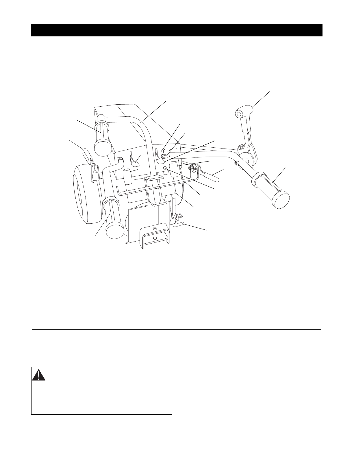
4.1 CONTROLS AND FEATURES
1
2
4
3
9
6
4
1. Direction Control Lever
2. Steering Brake Han dlebar (Opti onal)
3. Gear Shift Lever (Hi/Low Gear)
4. Operator Presence Control
5. Choke Control Knob (Models with Briggs & Stratton
Engines)
6. PTO Control
7. Ignition Switch
7
10
15
12
13
4
5
11
14
8
8. Kick Stand
9. Throttle Control
10. Hour meter
11. Brake Handle Cross Bar
12. Range Shift Handle (Two Speed Axle)
13. Parking Brake Handle (Optional on 8.5 HP)
14. Instruction Plate
15. Choke Lever (Models with Robin Engines)
16. Choke Control Knob (Models with Briggs & Stratton
OH0160
4.2 FILLING THE FUEL TANK
WARNING:
flammable. Keep fuel in a clean and tight
container. Keep fuel away from fire or heat.
Never put fuel in the fuel tank while the engine
is running or hot. Clean up any spilled fuel
before starting engin e.
Use caution with fuel. Fuel is very
Figure 1
Add fuel to the fuel tank as needed. See your engine
manual for the correct type and grade of fuel.
Put the unit in an open area. Stop the engine and lock
the brake. Clean the fuel cap and the area around the
fuel cap to prevent dirt from entering the fuel tank.
Remove the cap from the fuel tank. Fill the fuel tank.
Be careful not to spill the fuel. Install the cap on the fuel
tank and tighten. Clean up any spilled fuel before
starting the engine.
4 -10
4.3 GENERAL LUBRICATION
Control Linkage Lubrication
Every 25 hours of operation put a drop of engine oil on
the pivots of the throttle lever, the direction control
lever, the gear shift lever, the PTO control, and range
shift handle.
NOTE:
There are no grease fittings on the tractor.
Transmission
Capacity: 5 U.S. Quarts (4.7 liters)
Grade: SAE 30W API service class SF or higher
Viscosity: Summer: SAE 30W or SAE 10W-30
Winter: (32
• After every 100 hours of operation, check the level
of the lubricant in the transmission. Never operate
the tractor when the transmission oil level is below
the "LOW’ mark on the dipstick.
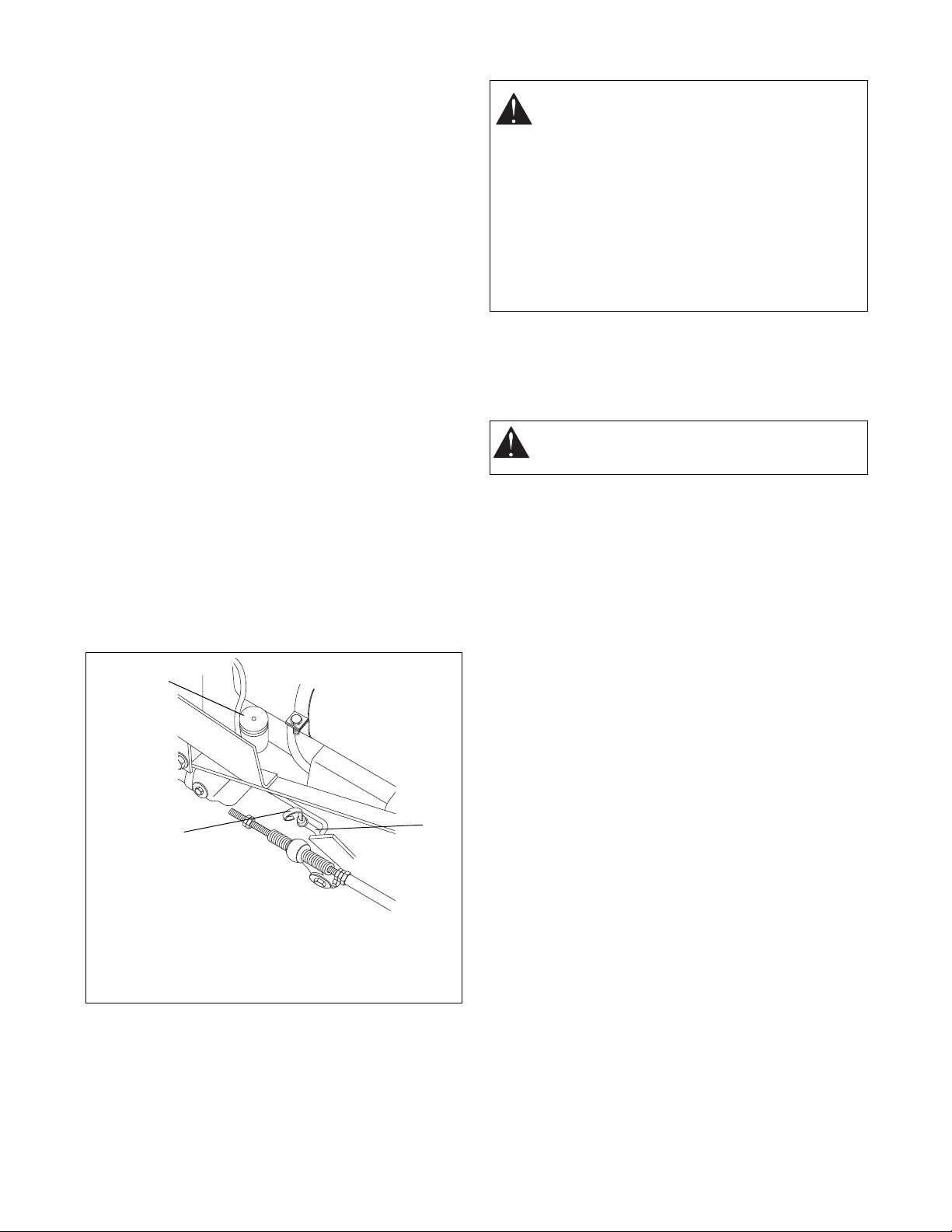
• Stop the engine and raise the hood. Make sure that
the tractor is level. Clean the dipstick tube and the
dipstick (Figure 2). Remove the dipstick, wipe it
with a clean cloth or towel and put it back in the
tube. Pull the dipstick out again and look at the oil.
• If the oil level is below the low mark on the dipstick,
clean the area around the filler plug and remove
the filler plug. Add new clean lubricant until the
dipstick indicates that the oil level is correct. See
specification. Install the filler plug and dipstick.
1
o
F or below) SAE 10W or
SAE 10W-30
CAUTION:
Before performing any service or
adjustments:
• Turn PT O switch "OFF".
• Park mower on a hard, flat, level surface.
• Place steering control levers in neutral
lock (fully outward) posi tion .
• Set parking brake.
• Turn ignition switch "OFF" and remove
key.
• Wait for all moving parts to stop.
4.4 FORWARD-REVERSE CLUTCH
ADJUSTMENT
• After 25 hours of operation, check the adjustment
of the forward-reverse clutch.
WARNING:
the forward-reverse clutch.
• The reverse clutch is adjusted correctly when the
direction control lever stops 15 degrees past
vertical to the rear. The lever should return to
neutral position from reverse w hen adjus ted
correctly.
• To adjust the reverse clutch, loosen the control
extension rod jam nuts on the end of the fwd-rev
control rod. Adjust the rear nut so that the direction
control lever stops 15 degrees past vertical to the
rear. Hold the rear nut and jam with the forward nut
(Figure 3) .
• The forward clutch is adjusted correctly when the
direction control lever is in the full forward position
and the large spring has a coil clearance of .010"
(.254 mm).
Stop the engine before adjusting
2
1. Oil Filler Plug
2. Dipstick
3. Dipstick Tube
Figure 2
3
OH0230
4 -11
2
1
6
7
1
7
7
5
4
9
1
7
8
3
10
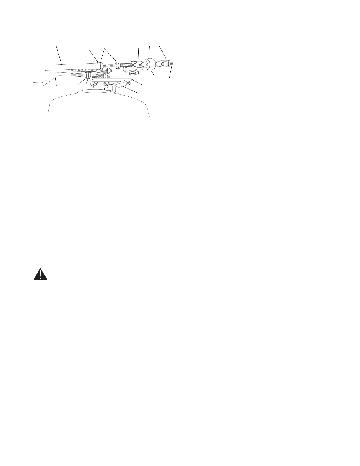
1. Jam Nuts
2. Fwd-Rev Control Rod
3. Control Extension Rod
4. Fwd-Rev Neutral
Spring
5. Large Spring
6. Brake Rod Assembly
7. Adjusting
nuts
8. Fwd-Re v Lever
Assembly
9. Adjustment Bracket
10. Cam Lever Arm
Figure 3
OH0181
• To adjust the forward clutch, put the direction
control in the forward position. Loosen the control
extension rod rear set of jam nuts on the fwd-rev
control rod. Adjust the forward nut until the large
spring coils are .010" (.254mm) apart. Hold the
forward nut and jam with the rear nut.
4.5 HI/LOW GEAR CLUTCH ADJUSTMENT
• After every 25 hours of operation, check the
adjustment of the gear clutch.
WARNING:
the gear clutch.
Stop the engine before adjusting
4.6 STEERING BRAKE ADJUSTMENT
(APPLICABLE MODELS)
• Park the unit in a level area. Put the parking brake
handle in the "OFF" (down) position. Loosen the
jam nuts on the right and left brake rod assemblies
(Figures 2 & 3). Turn the adjusting nuts until the
brake handle cross bar is parallel with the
instrument panel (Figure 1).
• Move the brake handlebar all the way to the right
and measure the distance from the right end edge
of the brake handle cross bar to the right side of
the instrument panel. Move the brake handlebar all
the way to the left and make the same
measurement on the left.
• Adjust the nuts until the difference between the two
measurements is 1/2" to 3/4" (13 to 19 mm). Turn
both adjusting nuts the same amount, clockwise to
increase the measurement difference or
counterclockwise to decrease the measurement
difference. Tighten the jam nuts.
• Loosen the jam nuts below the compression spring
(Figure 4) on the right side of the tractor and adjust
until one has the desired tension for the right
brake. Tighten the jam nuts.
IMPORTANT:
worn to rivet heads.
If correct braking action cannot be achieved after
performing the above procedures, do the following:
1. Loosen the 5/16-24 nut and bolt which fastens cam
lever arm to brake cam.
2. Remove cam lever arm from the brake cam. Rotate
the cam lever arm one spine to the rear and put
back on brake cam. Tighten nut and bolt.
Replace brake shoes before lining is
• The clutch is adjusted correctly when the gear shift
lever is in the "HIGH" or "LOW" position and the
spring coils are .010" (.254 mm) apart.
• To adjust the "HIGH" clutch, loosen and separate
the hi-low control rod jam nuts on the rear of the
control extension rod. Put the gear shift lever in the
"HIGH" position. Adjust the nut (front) near the
spring until the spring coils are .010" (.254 mm)
apart. Move the gear shift lever to the "NEUTRAL"
position. Hold the nut adjusted to the spring and
jam with the other (rear) nut (Figure 4).
• To adjust the "LOW" clutch, loosen and separate
the hi-lo control rod jam nuts on the end of the
control extension rod. Put the gear shift lever in the
"LOW" position. Adjust the nut (rear) near the
spring until the spring coils are 0.10" (.254 mm)
apart. Move the gear shift lever to the "NEUTRAL"
position. Hold the nut adjusted to the spring and
jam with the other (front) nut.
4 -12
1
1
9
2
3
4
2
5
2
7
1
8
1
2
6
1. Adjusting Nuts
2. Jam Nuts
3. Adjustment Bracket
4. Pivot Plate
5. Brake Rod Assembly
6. Hi-Lo Control Rod
4.7 PTO BRAKE ADJUSTMENT
• Adjust the PTO brake after every 100 hours of
operation.
WARNING:
the PTO brake.
• Remove the attachment and lower the rear of the
tractor to the ground. Carefully clean the front of
the transmission. Remove the quick hitch studs
from the transmission and remove the quick hitch
casting and PTO brake assembly (Figure 5).
NOTE:
The attachment gasket must be replaced if
damaged.
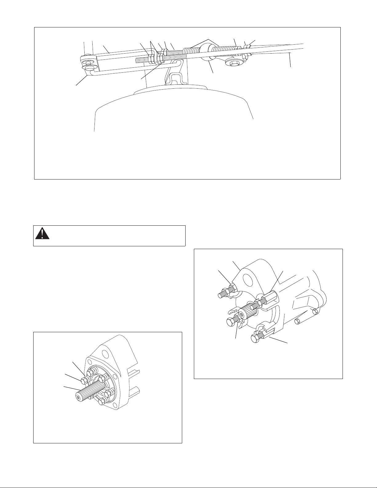
• Tighten all PTO brake bolts until the springs are
solid. Back all bolts up 1/2 turn (Figure 5).
Stop the engine before adjusting
7. Large Spring
8. Hi-Lo Lever Assembly
9. Control Extension Rod
Figure 4
NOTE:
Do not tighten the bolts in a circular sequence,
by tightening the bolt next to one which was just tightened. The bolts should be tightened in a cross
sequence, by tightening one bolt, then tightening the
bolt which is across from it on the plate. Continue
tightening the bolts in this sequence until all the bolts
are tightened.
1
2
2
OH0191
2
1
3
1. PTO Brake Bolts
2. Springs
Figure 5
3. PTO Shaft
OH0210
2
1. Quick Hitch Adapter
2. Quick Hitch Stud
2
Figure 6
• Make sure the trunnion block is on the shipper
shaft and held in place by the dog. The dog should
rest on the spiral teeth of the clutch dog plate.
Install the gasket.
• Align the splines on the quick hitch shaft with those
in the dog. Slide the quick hitch casting and PTO
brake assembly back into the place on the front of
the transmission. Install the quick hitch studs and
tighten.
4 -13
OH0200
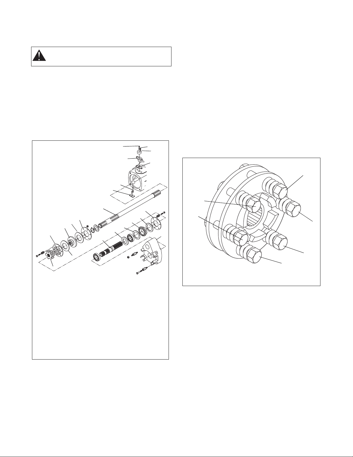
4.8 SLIP CLUTCH ADJUSTMENT
1
2
Figure 8
OH0220
3
2
4
5
6
• Adjust the slip clutch after every 100 hours of
operation.
WARNING:
the slip clutch.
• Remove the attachment and lower the rear of the
tractor to the ground. Carefully clean the front of
the transmission. Remove the quick hitch studs
from the transmission and remove the quick hitch
PTO assembly and PTO brake assembly (Figures
5 & 6).
NOTE:
The attachment gasket must be replaced if
damaged.
Stop the engine before adjusting
19
18
20
17
16
15
4
• Remove the dog and trunnion block. Disconnect
the wiring harness from the PTO brake interlock
switch and remove the shifter parts. Slide the
shipper shaft assembly through the top of the
advance casting. Slide the clutch assembly and
pinion shaft out of the transmission. Remove the
retaining ring and slide the clutch assembly off of
the pinion shaft. Turn all of the jam nuts
counterclockwise to loosen.
• Torque bolts in stages using the pattern shown in
Figure 8:
1. Tighten bolts down until the spring starts to
compress.
2. Tighten bolts to 80-85 in-lbs (9-9.6 Nm).
3. Tighten nuts to 165-170 in-lbs (18.6-19.2 Nm).
4. Finish tightening the nuts to 100-150 ft-lbs
(136-203 Nm).
10
11
12
14
13
2
5
6
1
2
3
7
9
8
1. Back Plate
2. Brake Disc
3. Dog Plate Brake
4. Trunnion Block
5. Seal
6. Quick Hitch Shaft
7. Quick Hitch Casting
8. Dog
9. Friction Washer
10.Dog Plate
Figure 7
11.Drive Plate
12.Friction Washer
13.Back Plate
14.Pinion Shaft
15.Shipper Shaft
16.Shipper Shaft Gasket
17.Shipper Shaft Body
18.Shipper Shaft
19.Set Screw
20.Roll Pin
NOTE:
Do not tighten the bolts in a circular sequence,
that is, by tightening the bolt next to one which was just
tightened. The bolts should be tightened in a cross
sequence, that is, by tightening one bolt, then
tightening the bolt which is across from it on the plate.
Continue tightening the bolts in this sequence until all
the bolts are tightened. (Figure 8)
• Slide the clutch assembly back onto the pinion
shaft, install the retaining ring and slide the pinion
shaft completely into the transmission. Install the
shipper shaft and other parts that were removed
previously. Make sure the trunnion block is on the
shipper shaft and held in place by the dog. The
dog should rest on the spiral teeth of the clutch dog
plate. Install the gasket. Align the splines on the
quick hitch shaft with those in the dog. Slide the
quick hitch casting and PTO brake assembly back
into place on the front of the transmission. Install
the quick hitch studs and tighten.
4 -14
 Loading...