

Gravely 89201800 User Manual

PTO
GRASS COLLECTION
SYSTEM
DESIGNED FOR:
MODEL 89201800
GRAVELY 200 SERIES MOWER
OPERATOR S MANUAL
ASSEMBLY OPERATION MAINTENANCE
MANUAL PART#: 00191300 $4.00 REV:(Q0314) 1

PTO GRASS COLLECTION SYSTEM
TABLE OF CONTENTS
SECTION PAGE
Safety - ------------------------------2
Safety Alert Symbols----------------------3
Warranty -----------------------------4
I INTRODUCTION AND DESCRIPTION- - ------------5
1-1 Introduction - ------------------------5
1-2 Description - ------------------------5
II INSTALLATION FOR USE ----------------------5
2-1 Preparation Of Mower ------------------5
2-2 Attaching Lower Frame Legs - - ------------6
2-3 Attaching The Top Main Frame Assembly ------7
2-4 Attaching The Lift Handle To The Aluminum
Grass Container- ------------------------7
2-5 Attaching The Aluminum Grass Container To
The Mower ----------------------------9
2-6 Aluminum Grass Container Inlet Attachment ----9
2-7 Adjusting The Dump Mechanism -----------9
2-8 Belt Installation -----------------------12
2-9 Cam Assembly Adjustment - - - ------------12
2-10 Attachment Of The Boot To The Mower Deck - - 12
Safety
SECTION PAGE
2-11 Adjustment Of The Lengths Of The Hoses ----13
2-12 Attachment Of The Upper Hose -----------13
2-13 Attachment Of The Lower Hose To The
Blower Cone - - - ------------------------13
2-14 Attachment Of The Lower Hose To The Boot---13
2-15 Front Weight Assembly-----------------13
2-16 Final Checks -----------------------14
III OPERATING INSTRUCTIONS - ------------------11
3-1 General Safety -----------------------11
3-2 Operation & Tips On Mowing- - ------------11
3-3 Disengagement Of The Blower ------------11
3-4 Unloading The Collection System -----------11
IV MAINTENANCE ----------------------------11
4-1 Maintenance Checklist ------------------11
4-2 Lubrication- - ------------------------12
V PARTS AND SERVICE ------------------------12
5-1 Parts And Service Information - ------------12
Safety Decals - - ------------------------13
Torque Specifications - - - ------------------14
Notes- - ------------------------------15
1.
Read the operator’s manual carefully and familiarize yourself with the proper use of your attachment. Do not allow
anyone who is not acquainted with the Safety Instructions to use your attachment.
2.
Know the controls and how to stop quickly. READ THE OPERATOR’S MANUAL!
3.
Do not allow children to operate the vehicle. Do not allow adults to operate it without proper instruction.
4.
Be especially watchful of children and pets darting into the area while operating.
5.
Keep your eyes and mind on your unit while mowing or operating your attachment. Don’t let others distract you.
6.
Do not attempt to operate your unit or mower when not in the driver’s seat.
7.
Always stop unit when emptying the container.
8.
Stop unit, shut off deck and attachment, set parking brake, shut off mower engine and remove spark plug wire
before removing clogs or removing or replacing hose, boot, blower cone, or performing any maintenance.
9.
Mow up and down the face of slopes (not steeper than 10 degrees); never across the face of the slope.
10.
It is recommended that the container be kept only half full when negotiating any slopes. Start mowing on slopes
when the container is empty.
11.
Inspect your lawn and remove any foreign objects before mowing. Never deliberately run the mower across any
foreign object.
12.
Wear ear protection if the noise level is offensive.
13.
Wear eye protection to prevent debris from damaging your eyes.
2

SAFETY
WARNING!
vacuum collector adapter are fastened securely in place.
WARNING!
blades and the blower impeller have stopped rotating.
WARNING!
STOPPING THE MOWER’S ENGINE AND WAITING FOR ALL MOVING PARTS TO COME TO A
COMPLETE STOP.
WARNING!
across the face. attempt to mow excessively steep slopes, and use caution when turning on any slope.
NEVER
Do not work around the mower deck boot or the blower area until you are certain that the mower
To avoid serious injury, perform maintenance on the vacuum collector;
Set the parking brake. Always remove the ignition key before beginning maintenance.
For your own personal safety, mow and the face of slopes and
NEVER
operate the unit unless the discharge guard and either the deflector assembly or the
ONLY AFTER
ALWAYS UP DOWN NEVER
Safety Alert Symbol
“ATTENTION! BECOME
!
This Safety Alert Symbol means:
ALERT! YOUR SAFETY IS INVOLVED!”
This symbol is used to call attention to safety precautions that
Should be followed by the operator to avoid accidents. When
you see this symbol, carefully read the message that follows
and heed its advice. Failure to comply with safety precautions
could result in death or serious bodily injury.
Safety Signs
The signal words and are used on the equipment safety signs. These words are
intended to alert the viewer to the existence and the degree of hazard seriousness.
!
!
Black letters on ORANGE
!
Black letters on YELLOW
DANGER, WARNING, CAUTION
This signal word indicates a potentially hazardous situation which, if not
DANGER
White letters on RED
WARNING
CAUTION
avoided, will result in death or serious injury.
This signal word indicates a potentially hazardous situation which, if not
avoided, could result in death or serious injury.
It may also be used to alert against unsafe practices.
This signal word indicates a potentially hazardous situation exist which, if
not avoided, will result in minor or moderate injury.
It may also be used to alert against unsafe practices.
3
WARRANTY
4
SECTION I
INTRODUCTION AND DESCRIPTION
1-1 Introduction
We are pleased to have you as a Gravely customer.
Your collection system has been designed to give you a
low maintenance, simple, and effective way to collect the
grass clippings from your mower. This manual is
provided to give you the necessary instructions to
properly mount and operate the collection system on
your mower. Please read this manual thoroughly.
Understand what each control is for and how to use it.
Observe all safety decal precautions on the machine and
noted throughout the manual.
NOTE:
or bottom are as viewed from the normal operator’s
position on the mower.
All references made to right, left, front, rear, top
1-2 Description
The collection system is designed for turf maintenance
where there is a need to collect the grass clippings as
the mower cuts the turf. It is also good for picking up
leaves and twigs in pre-season and post-season cleanup.
The blower, mounted on the right side of the unit, uses a
belt and gearbox system from the engine PTO shaft.
Drive train protection comes through belt slippage. The
blower draws grass clippings from the discharge area of
the cutter deck up to the aluminum container mounted
over the rear portion of the mower frame. The operator
can engage the blower with a push of the over-center
linkage on the right side of the unit. Once the container
is full of clippings, the operator can easily push and raise
the lift handle, releasing the container’s rear door and
the container will pivot towards the ground.
Figure 1
Section II
INSTALLATION FOR USE
2-1 Preparation Of Mower
Carefully dismantle wooden shipping crate from around
the components. Cut retaining straps and separate the
parts. The collection system will have various parts
located inside. Remove and sort all parts for easy
identification.
NOTE:
study the exploded drawings on pages 8,9,10,11 and 12.
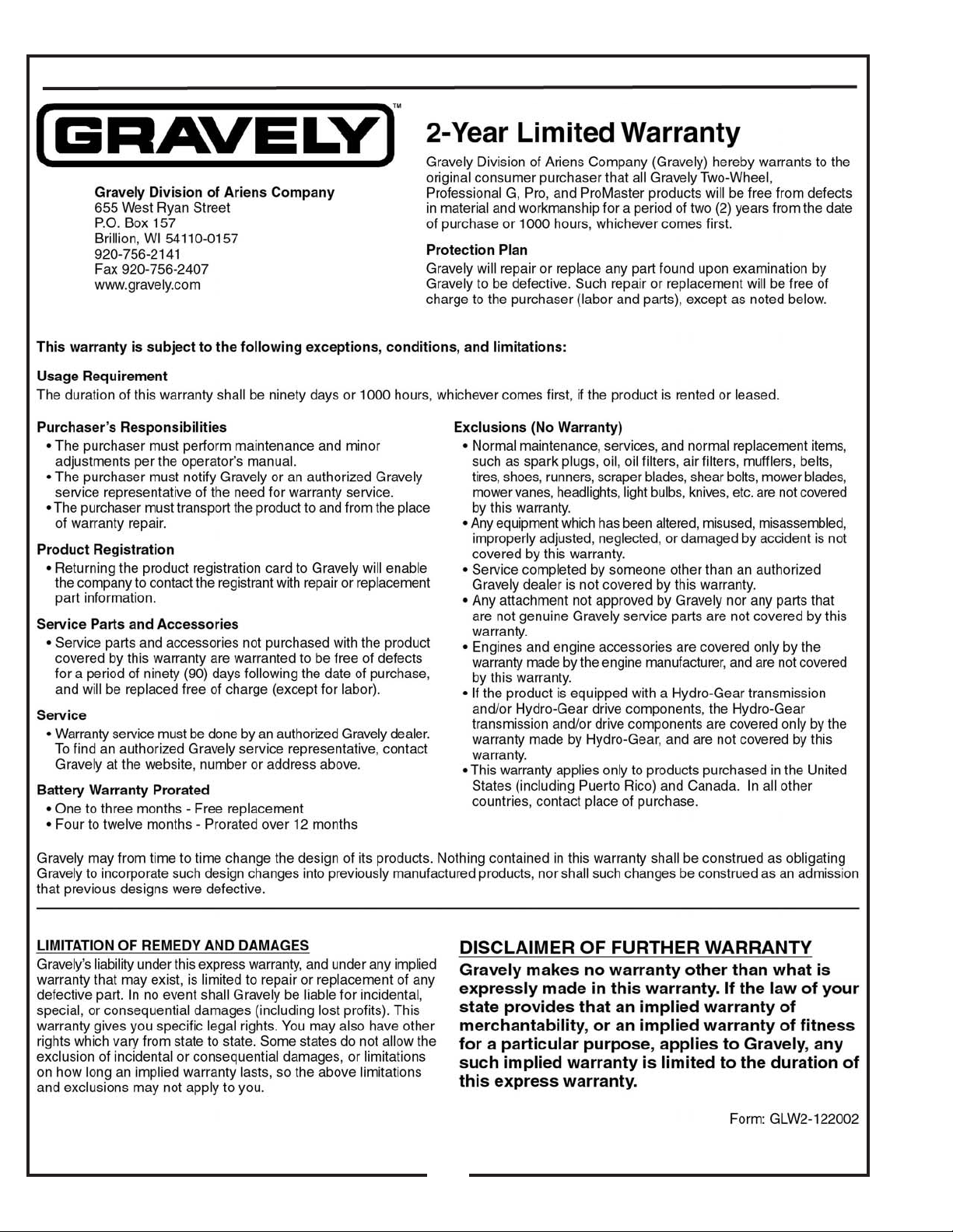
From the underside of the mower engine remove the bolt
and bushing from the electric clutch assembly. Replace
these parts with the engine pulley assembly
P#(00194800), 7/16” lock washer P#(06309300), and
7/16”-20 x 4” HHCS P#(05966800). The added pulley
will power the collection system. Note that the center of
the hub that is extended should be upward toward the
engine . Torque the bolt to 55 ft./lbs.
Parking Brake Setting
For the added weight of the collection system, the
parking brake must be re-adjusted. To do this, first
Remove the rear wheels from the mower. Once
removed, reset the spring and the stop gap per the
dimensions in the diagram (Figure 2). Replace the
wheels when completed and torque each bolt to 51-72
ft./lbs.
1.432”
Before each step of assembly it will help to
(Figure 1)
Figure 2
0.0” to 0.0625
Engine Pulley Assy.
Electric Clutch
5
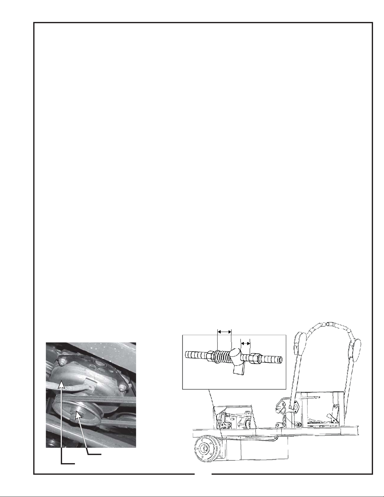
2-2 Attaching Lower Frame Legs
Safety Interlock Harness Connection
Remove the (3) bolts (Figure 3) from each side of the
rear of the mower. Keep the bolt, from each side, that
threads through the mower’s rear frame. Place the left
lower main frame leg P#(00197700) onto the rear of the
mower and fasten by using (2) 3/8”-16 x 3” HHCS
P#(05957800) and (2) 3/8”-16 flange nuts
P#(06542000). Use the existing bolt removed from the
mower to fasten the front side of the leg. Repeat this
step to fasten the right PTO assembly P#(00195500)
(Figure 4).
Figure 3 Left Lower Main
Frame Leg.
Left Lower Main Frame Leg
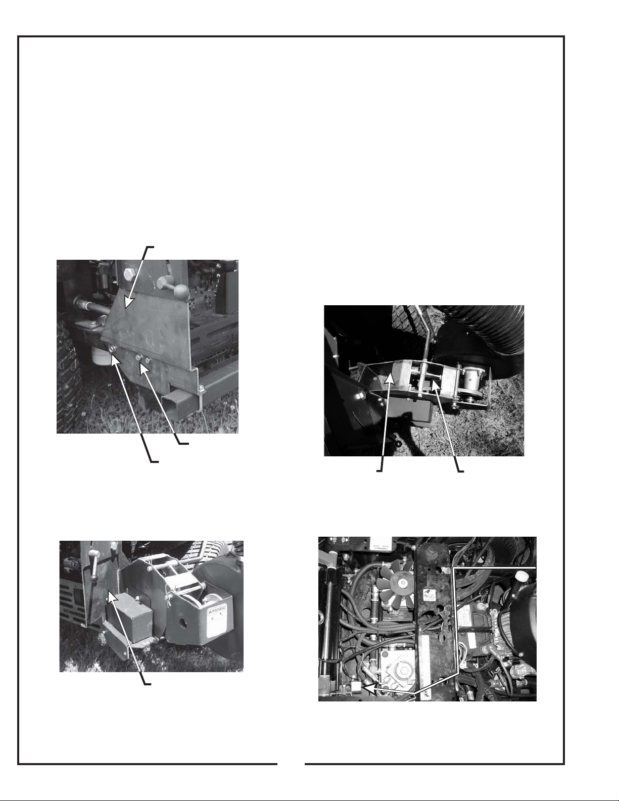
The safety interlock harness is located inside of the right
PTO arm assembly (Figure 5). To install the harness to
the mower, lift the hood of the mower for engine
compartment access. Route the harness as shown
towards the parking brake switch bracket on the mower
(Figure 6). Fasten the harness to the mower’s rear frame
by using (1) zip tie P#(07517300) to prevent the harness
from rubbing the mower’s tire. Next, remove the (2) bolts
(Figure 7) from the parking brake switch bracket for
access to the brown/yellow and red/violet wires. Remove
the brown/yellow wire from the parking brake switch and
connect to the brown/yellow wire of the harness.
Connect the red/violet wire to the parking brake switch,
where the brown/yellow wire was removed (Figure
8).Replace the bolts removed from the parking brake
switch.
Figure 5
Location Of Safety Interlock Harness
Figure 4
Right PTO Assembly
3/8” x 3” HHCS
Existing Bolt
Right PTO Assembly
Free End Of
Harness For
Routing
Figure 6 Safety Interlock Harness Route
Harness
Connected
Here
6
 Loading...