

Gravely 5000 Series Setup Instructions
PART
NUMBERtS):
5000 SERIES
~GRAVEL'l
e
NAME:
5000 SERIES
TRACTo-R-
SETUP
INSTRUCTIONS
These
instructions
give
the
procedure
for
assembling
the
5000Series
tractor.
All
referencetoright
side,
left
side,
front
and
rear are
given
from
the
operator's
position.
The
wheel
assemblies
are
not
with
the
tractor.
Get
wheel assemblies as needed.
I
4
1.0
HOW
TO
TIGHTEN
THE
BOLTS
Tighten
the
bolts
used
to
assemble
the
5000
Series
tractor
to
the
torque
given in
the
bolt
torque
specifications
unless
shown
differently.
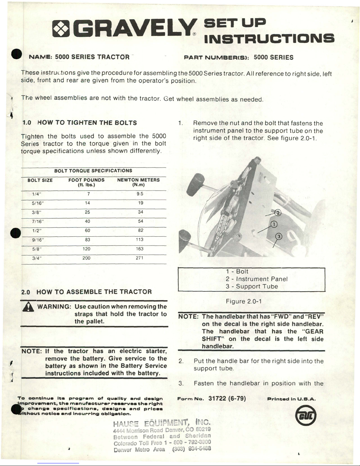
1.
Remove
the
nut
and
the
bolt
that
fastens
the
instrument
paneltothe
support
tubeonthe
right
sideofthe
tractor.
See
figure
2.0-1.
BOLTTORQUE
SPECIFICATIONS
BOLT
SIZE
FOOT
POUNDS
NEWTON
METERS
(ft.
Ibs.)
(N.m)
1/4"
7
9.5
5/16"
14
19
3/8"
25
34
7/16"
40
54
/
e
1/2"
60
82
9/16"
83
113
,
5/8"
120
163
3/4"
200
271
NOTE:
The
handlebar
that
has
"FWD"
and
"REV"
on
the
decal is
the
right
side
handlebar.
The
handlebar
that
has
the
"GEAR
SHIFT"
on
the
decal
is
the
left
side
handlebar.
I
{
1
2.0
HOW
TO
ASSEMBLE
THE
TRACTOR
A
WARNING:
Use
caution
when
removing
the
straps
that
hold
the
tractor
to
the
pallet.
INOTE:
If
the
tractor
has an
electric
starter,
remove
the
battery.
Give servicetothe
battery
as
showninthe
Battery
Service
instructions
included
with
the
battery.
2.
3.
1 -
Bolt
2 -
Instrument
Panel
3 -
Support
Tube
Figure
2.0-1
Put
the
handle
bar
for
the
right
side
into
the
support
tube.
Fasten
the
handlebar
in
position
with
the
Form
No.
31722 (6-79)
To
oon"'nu.
I".
program
of
qu.llty
endd••
lgn
~
mprov.m.nt:,
"h.
manuf.ctur.r
r
•••rv••
"h.
right:
cheng
••
p.clflca"'on.,
d••'gn
••
nd
prlc
••
'thou"
no"'c.
and
Incurring
obllge"'on.
HP'tt
~.=
"
UH'ft.
r:NT,
U,;~C.
4444 Morrison Road Denvr.CO
8::'219
Betwoon
Federal
and
Sheridan
Colorado Toll Freo 1 -
800
- 792-3200
Denver Metro Ar a (3 ) 934- 488
Printed
In
U.S.A.
BrentChalmers.com
bolt
and
nut
that
was removed in step1.See
figure
2.0-2.
Figure
2.0-2
1 -
Control
Rod
2 -
Control
Lever
3 - Clevis Pin
Figure
2.0-4
4.
5.
Remove
the
nut
and
bolt
from
the
support
tubeonthe
left side. Put
the
other
handlebar
into
the
support
and fasten
the
handlebar
in
position
with
the
bolt
and nut.
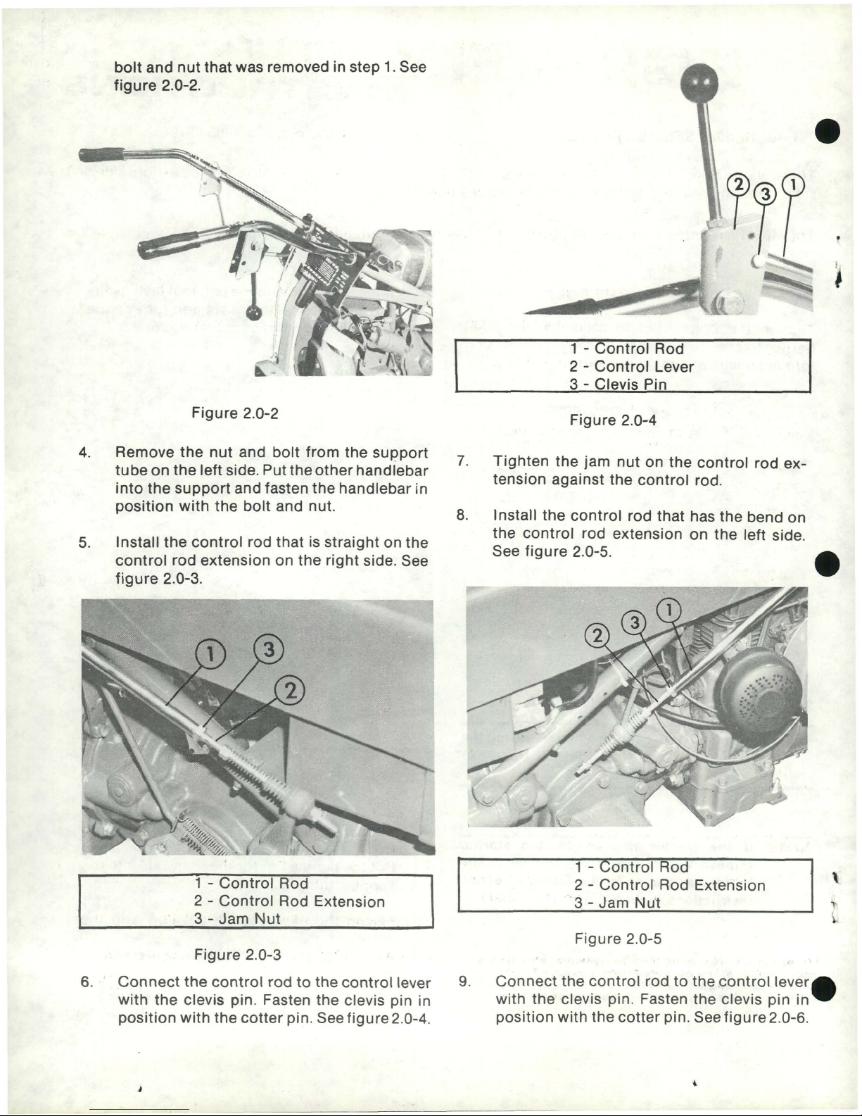
Install
the
control
rod
thatisstraightonthe
control
rod
extensiononthe
right
side. See
figure
2.0-3.
1 -
Control
Rod
2 -
Control
Rod Extension
3 -
Jam
Nut
7.
8.
Tighten
the
jam
nut
on
the
control
rod
ex-
tension
against
the
control
rod.
Install
the
control
rod
that has
the
bend
on
the
control
rod
extension
on
the
left side.
See
figure
2.0-5.
1 -
Control
Rod
2 -
Control
Rod Extension
'3-Jam
Nu't
\
l
Figure
2.0-3
6.
Connect
the
control
rodtothe
control
lever
with
the
clevis pin. Fasten
the
clevis pin in
position
with
the
cotter
pin. See
figure
2.0-4.
)
9.
Figure
2.0-5
-
Connect
the
control
rodtothe
control
lever_
with
the
clevis pin. Fasten
the
clevis
pin
in.
position
with
the
cotter
pin. See
figure
2.0-6.
BrentChalmers.com
 Loading...