

Page 1
zu Best.-Nr. 6288
Bauanleitung
NEMESIS
GRAUPNER GmbH & Co. KG D-73230 KIRCHHEIM/TECK GERMANY
Änderungen vorbehalten! Keine Haftung für Druckfehler! Id.-Nr. 50414 11/2004
1
Made in Germany
Page 2

Bitte unbedingt die folgenden Sicherheitshinweise beachten.
Sofern das Modell an eine andere Person weitergegeben wird, müssen diese
Sicherheitshinweise, bzw. die komplette Bauanleitung zur Beachtung weitergegeben
werden.
Sicherheitshinweise
Vor dem Versuch der ersten Inbetriebnahme muss die gesamte Betriebs- bzw. Bauanleitung sorgfältig
gelesen werden. Sie alleine sind verantwortlich für den sicheren Betrieb Ihres RC-Flugmodells. Bei
Jugendlichen muss der Bau und Betrieb von einem Erwachsenen, der mit den Gegebenheiten und
möglichen Gefahren eines RC-Flugmodells vertraut ist, verantwortlich überwacht werden.
Rechtlich gesehen, ist ein Flugmodell ein Luftfahrzeug und unterliegt entsprechenden Gesetzen, die
unbedingt eingehalten werden müssen. Die Broschüre "Modellflugrecht", Best.-Nr. 8034.01 stellt eine
Zusammenfassung dieser Gesetze dar; sie kann auch beim Fachhandel eingesehen werden. Ferner
müssen postalische Auflagen, für die Fernlenkanlage, beachtet werden. Entsprechende Hinweise finden
Sie in der Bedienungsanleitung Ihrer Fernsteueranlage.
Es dürfen nur die dem Bausatz enthaltenen Teile, sowie die ausdrücklich von uns empfohlenen OriginalGraupner-Zubehör- und Ersatzteile verwendet werden. Wird eine Komponente der Antriebseinheit
geändert, ist ein sicherer Betrieb nicht mehr gewährleistet und es erlischt jeglicher Garantieanspruch.
Kurzschlüsse und Falschpolungen vermeiden.
Durch die hohe Energie der Batterien besteht Explosions- und Brandgefahr.
Ein RC-Flugmodell kann nur funktionsfähig sein und den Erwartungen entsprechen, wenn es im Sinne
der Bauanleitung sorgfältigst gebaut wurde. Nur ein vorsichtiger und überlegter Umgang beim Betrieb
schützt vor Personen- und Sachschäden. Niemand würde sich in ein Segelflugzeug setzen und - ohne
vorausgegangene Schulung - versuchen, damit zu fliegen. Erfolgreiches Modellfliegen erfordert ebenso
eine Ausbildungs- bzw. Übungsphase.
Der Hersteller hat jedoch keine Möglichkeit, den Bau und den Betrieb eines RC-Flugmodells zu
beeinflussen. Deshalb wird hiermit auf die Gefahren nachdrücklich hingewiesen und jede Haftung dafür
abgelehnt.
Bitte wenden Sie sich dazu an erfahrene Modellflieger, an Vereine oder Modellflugschulen. Ferner sei auf
den Fachhandel und die einschlägige Fachpresse verwiesen. Am besten als Club-Mitglied auf
zugelassenem Modellflugplatz fliegen.
Klebstoffe enthalten Inhaltsstoffe, die unter Umständen gesundheitsschädlich sein können. Beachten Sie
daher unbedingt auch die entsprechenden Hinweise und Warnungen der Hersteller.
Der Betreiber muss im Besitz seiner vollen körperlichen und geistigen Fähigkeiten sein. Wie beim
Autofahren, ist der Betrieb des Flugmodells unter Alkohol oder Drogeneinwirkung nicht erlaubt.
Informieren Sie Passanten und Zuschauer vor der Inbetriebnahme über Gefahren, die von Ihrem Modell
ausgehen und ermahnen Sie diese, sich in ausreichendem Schutzabstand aufzuhalten.
Stets mit dem notwendigen Sicherheitsabstand zu Personen oder Hindernissen fliegen, nie Personen
überfliegen oder auf sie zufliegen!
Modellflug darf nur bei Außentemperaturen von - 5º C bis + 35º C betrieben werden. Extreme
Temperaturen können zu Veränderungen der Batteriekapazität, der Werkstoffeigenschaften sowie z. B. zu
mangelhaften Klebeverbindungen u.s.w. führen.
Jeder Modellflieger hat sich so zu verhalten, dass die öffentliche Sicherheit, insbesondere andere
Personen und Sachen, sowie der Ablauf des Modellflugbetriebs nicht gefährdet oder gestört wird.
Das Flugmodell niemals in der Nähe von Hochspannungsleitungen, Industriegeländen, in Wohngebieten,
öffentlichen Straßen, Schulhöfen oder Spielplätzen usw. fliegen lassen.
Überprüfung vor dem Start
Vor jedem Einsatz korrekte Funktion überprüfen. Dazu den Sender einschalten, ebenso den Empfänger.
Senderantenne ausziehen, kontrollieren, ob alle Ruder in Neutrallage stehen, einwandfrei funktionieren
und seitenrichtig ausschlagen. Diese Überprüfung bei laufendem Motor wiederholen, während ein Helfer
das Modell festhält.
Beim erstmaligen Steuern eines Flugmodells ist es von Vorteil, wenn ein erfahrener Helfer bei der
Überprüfung und den ersten Flügen zur Seite steht.
2
Page 3

Warnungen müssen unbedingt beachtet werden. Sie beziehen sich auf Dinge und Vorgänge, die bei einer
Nichtbeachtung zu schweren - in Extremfällen tödlichen Verletzungen oder bleibenden Schäden führen
können.
Luftschrauben die durch einen Motor angetrieben werden, stellen eine ständige Verletzungsgefahr dar.
Sie dürfen mit keinem Körperteil berührt werden! Eine schnell drehende Luftschraube kann z. B. einen
Finger einschneiden!
Sich niemals in oder vor der Drehebene von Luftschrauben aufhalten! Es könnte sich doch einmal ein
Teil davon oder die komplette Luftschraube lösen und mit hoher Geschwindigkeit und viel Energie
wegfliegen und Sie oder Dritte treffen, dies kann u. U. zu schweren Verletzungen führen. Darauf achten,
dass kein sonstiger Gegenstand mit einer laufenden Luftschraube in Berührung kommt!
Die Blockierung der Luftschraube, durch irgendwelche Teile, muss ausgeschlossen sein.
Überprüfen Sie vor jeder Inbetriebnahme das Modell und alle an ihm gekoppelten Teile (z. B.
Luftschrauben, RC-Teile usw.) auf festen Sitz und mögliche Beschädigungen. Das Modell darf erst nach
Beseitigung aller Mängel in Betrieb genommen werden.
Vergewissern sie sich, dass die verwendete Sender-Frequenz frei ist. Erst dann den Sender einschalten!
Funkstörungen, verursacht durch Unbekannte, können stets ohne Vorwarnung auftreten! Das Modell ist
dann steuerlos und unberechenbar! Fernlenkanlage nicht unbeaufsichtigt lassen, um ein Betätigen durch
Dritte zu verhindern.
Elektromotor nur einschalten, wenn nichts im Drehbereich der Luftschraube ist. Nicht versuchen, die
laufende Luftschraube anzuhalten. Elektromotor mit Luftschraube nur im eingebauten Zustand betreiben.
Die Fluglage des Modells muss während des gesamten Fluges immer eindeutig erkennbar sein, um
immer ein sicheres Steuern und Ausweichen zu gewährleisten. Machen sich während des Fluges
Funktionsbeeinträchtigungen/Störungen bemerkbar, muss aus Sicherheitsgründen sofort die Landung
eingeleitet werden. Sie haben anderen Luftfahrzeugen stets auszuweichen. Start- und Landeflächen
müssen frei von Personen und sonstigen Hindernissen sein.
Immer auf vollgeladene Batterien achten, da sonst keine einwandfreie Funktion der RC-Anlage
gewährleistet ist.
Niemals heiß gewordene, defekte oder beschädigte Batterien verwenden. Es sind stets die
Gebrauchsvorschriften des Batterieherstellers zu beachten.
Vor jedem Flug eine Überprüfung der kompletten RC-Anlage, sowie des Flugmodells, auf volle
Funktionstüchtigkeit und Reichweite durchführen.
Dabei ist zu beachten, dass bei der Inbetriebnahme die Motorsteuerfunktion am Sender immer zuerst in
AUS-Stellung gebracht wird. Danach Sender und dann erst Empfangsanlage einschalten, um ein
unkontrolliertes Anlaufen des Elektromotors zu vermeiden. Gleichfalls gilt immer zuerst Empfangsanlage
ausschalten, danach erst den Sender.
Überprüfen Sie, dass die Ruder sich entsprechend der Steuerknüppelbetätigung bewegen.
Nach Gebrauch die Batterie aus dem Modell nehmen und nur im entladenen Zustand für Kinder
unzugänglich, bei ca. + 5º bis + 25º C aufbewahren.
Mit diesen Hinweisen soll auf die vielfältigen Gefahren hingewiesen werden, die durch unsachgemäße
und verantwortungslose Handhabung entstehen können. Richtig und gewissenhaft betrieben ist
Modellflug eine kreative, lehrreiche und erholsame Freizeitgestaltung.
Haftungsausschluss
Sowohl die Einhaltung der Montage- und Betriebsanleitung in Zusammenhang mit dem Modell als auch
die Bedienung und Methoden bei Installation, Betrieb, Verwendung und Wartung der
Fernsteuerungsanlagen können von der Firma Graupner nicht überwacht werden. Daher übernimmt die
Firma Graupner keinerlei Haftung für Verluste, Schäden oder Kosten, die sich aus der fehlerhaften
Verwendung und Betrieb ergeben oder in irgendeiner Weise damit zusammenhängen.
Soweit vom Gesetzgeber nicht zwingend vorgeschrieben, ist die Verpflichtung der Firma Graupner zur
Leistung von Schadensersatz, gleich aus welchem Rechtsgrund, begrenzt auf den Rechnungswert der an
dem schadenstiftenden Ereignis unmittelbar beteiligten Warenmenge der Firma Graupner. Dies gilt nicht,
soweit die Firma Graupner nach zwingenden gesetzlichen Vorschriften wegen Vorsatz oder grober
Fahrlässigkeit unbeschränkt haftet.
3
Page 4

Allgemeines
Das Modell NEMESIS ist ein außergewöhnliches RC-Elektroflugmodell, das vor
allem erfahrenen Modellfliegern viel Flugvergnügen bereitet. Für Modellbauanfänger
ist dieses Model nicht geeignet. Das Modell ist weitgehend vorgearbeitet, die
nachfolgend beschriebenen Bauschritte sind jedoch mit größter Sorgfalt
auszuführen, damit ein sicherer und erfolgreicher Einsatz des Modells gewährleistet
ist.
Aus Sicherheitsgründen dürfen nur die im Katalog bzw. die nachfolgend aufgeführten
Zubehörteile eingesetzt werden. Das Fluggewicht von 130 g darf keinesfalls
überschritten werden.
Elektroantrieb und Zubehör
Elektromotor
Best.-Nr.
SPEED 250
7,2 V
6374
Luftschraube
Best.-Nr.
CAM SPEED
PROP
10x8 cm
1361.10.8
Präzisionsspinner
Best.-Nr.
Ø 20mm
6033.22
Antriebsbatterie
Best.-Nr.
2-LiPo 240
7,4 V/0,24Ah
7600.2
Drehzahlregler
Best.-Nr.
PICO 8
7171
RC-Zubehör
Zur Steuerung des Modells sind ausschließlich FM-Fernsteueranlagen wie z. B. X306 bis MC 24 geeignet. Weitere Informationen über RC-Zubehörteile sind dem
Hauptkatalog FS zu entnehmen.
Abb. Nr. 1 X-306 FM 35 mit 2 zusätzlichen Servos C 100 und Empfänger XP 10FM
Zum Betrieb des Modells sind nachfolgend aufgeführte Zubehörteile erforderlich:
1 FM Fernlenkset X-306 FM 35 Best.-Nr. 4708
2 Servos C100 Best.-Nr. 5105
4
Page 5
Zubehör
Ladegerät TURBOMAT 6 PLUS (nur für Sender!) Best.-Nr. 6428
Senderbatterie (8 Stück erforderlich) Best.-Nr. 98843
Senderladekabel Best.-Nr. 3423
LiPo Charger 4 (nur für LiPo Batterie Best.-Nr. 7600.2) Best.-Nr. 6437
Verlängerungskabel 100 mm Best.-Nr. 3935.11
Erforderliche Werkzeuge und Klebstoffe
Balsamesser Best.-Nr. 980
Schraubendreher Best.-Nr. 810
Sechskantschraubendreher SW 1,5 Best.-Nr. 5735.1,5
Feinlötgerät PICO 30TS Best.-Nr. 826
Radiolötzinn Best.-Nr. 1176.1
Styropor Sekundenkleber Best.-Nr. 5820
Aktivator für Sekundenkleber Best.-Nr. 953.150
Nassschleifpapier 400 Best.-Nr. 700.2
Heißluftföhn
Faserstift schwarz
Seitenschneider
Mini-Flachzange
Papierschere
Bauanleitung
Achtung! Die Styroporteile dürfen keinesfalls mit den Klebstoffen UHU hart,
UHU acrylit usw. in Berührung kommen. Durch diese Klebstoffe wird der
Hartschaum aufgelöst. Weiterhin werden die Styroporteile durch
Hitzeeinwirkung über 60° C beschädigt.
Die Styroporteile sind besonders empfindlich gegen Kerbeinwirkung durch
scharfkantige Teile. Beim Zusammenbau immer auf eine saubere, glatte Unterlage
achten oder auf einer Schaumstoffunterlage arbeiten. Styropor-Sekundenkleber als
Klebstoff verwenden. Den Klebstoff generell sparsam verwenden. Besonders darauf
achten, dass kein Restklebstoff auf die Oberfläche des Modells gelangt.
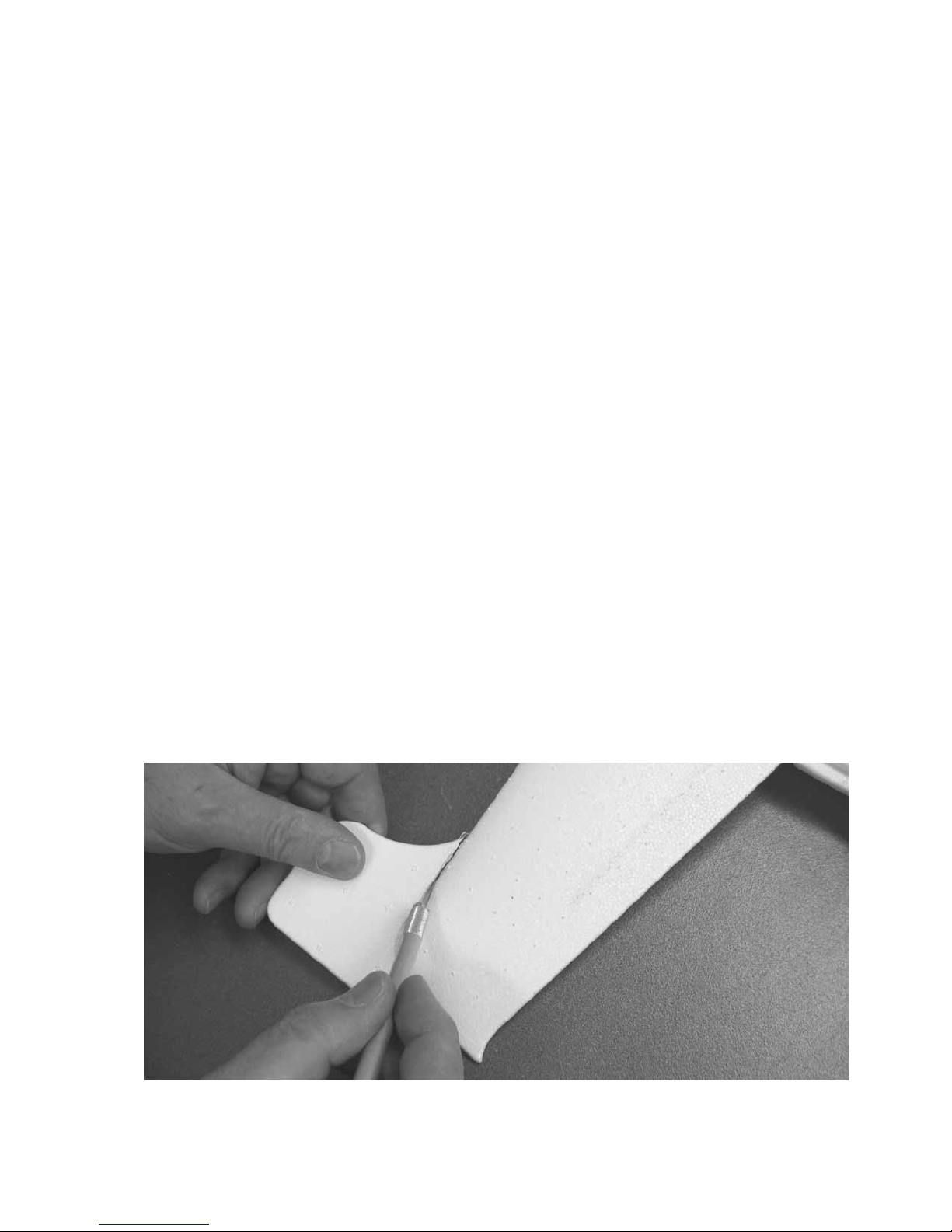
Abb. Nr. 2 Zuerst die fertigungstechnisch bedingten Ränder von Tragfläche und
Rumpf (1) abtrennen.
5
Page 6
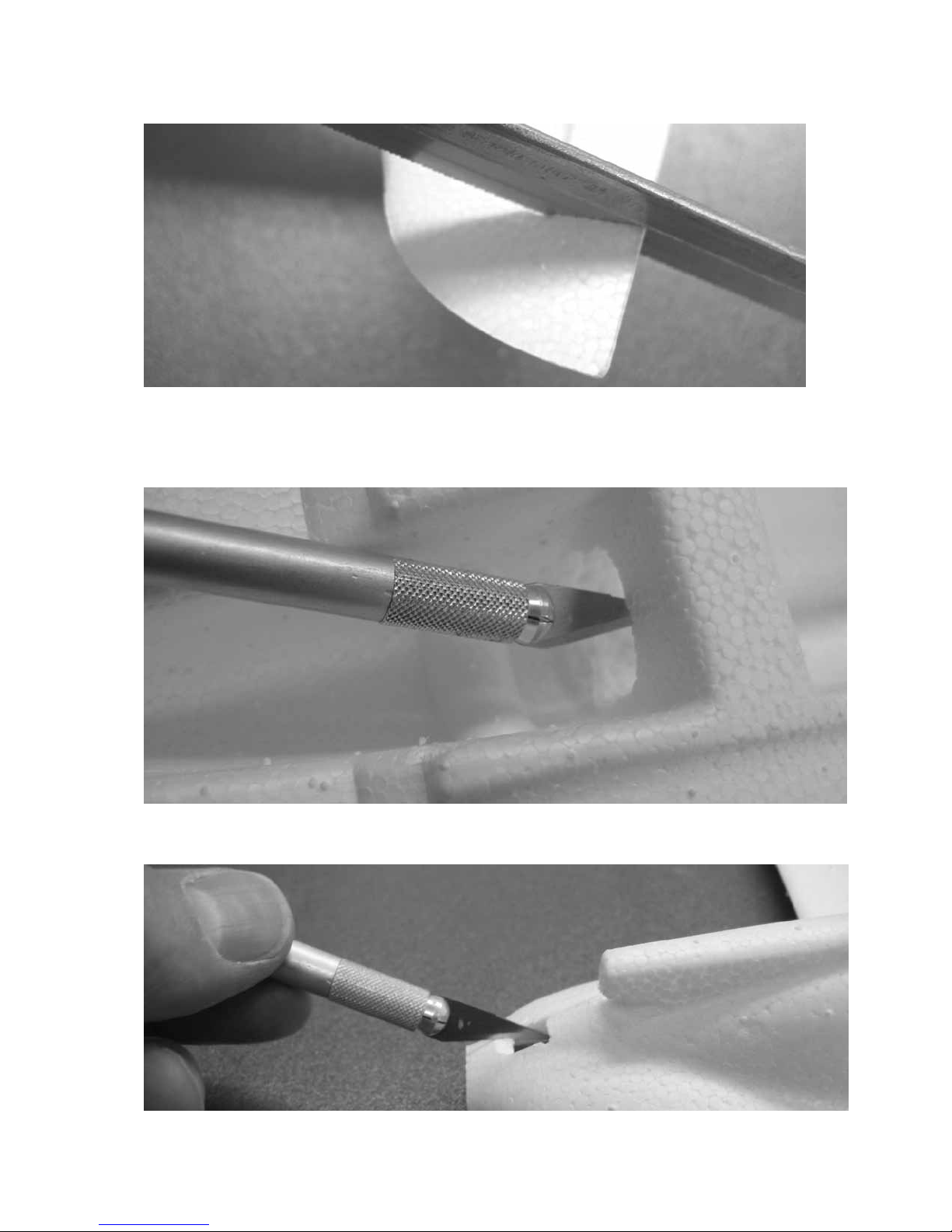
Abb. Nr. 3 Die Einschnitte für Quer- und Höhenruder ausführen, diese sind jeweils
auf der Unterseite markiert. Die Ruder anschließend vorsichtig vorbiegen, sodass sie
sich im Bereich von ca. 10° nach oben und unten leicht bewegen lassen.
Abb. Nr. 4 Unterhalb des Holmsteges eine Durchführungsöffnung aussparen.
6
Page 7

Abb. Nr. 5 Den Kühllufteinlass für den SPEED 250 Elektromotor ausschneiden, und
den original Lufteinlass entsprechend der Abbildung formen.
Abb. Nr. 6
Den Elektromotor entstören, die Kondensatoren (liegen dem Motor und
dem Drehzahlregler bei) gemäß Abbildung anlöten, das Motorgehäuse an den
Lötpunkten überschleifen und reinigen.
Abb. Nr. 7 Die Luftschraube mit Spinner montieren und den Drehzahlregler gemäß
Abbildung anlöten. Achtung, auf richtige Polung achten, das weiße (+) Kabel an
den Motoranschluss mit dem roten Markierungspunkt anlöten
Das 100 mm lange Verlängerungskabel wird zwischen Drehzahlregler und
Empfänger benötigt.
Besonderer Hinweis beim Einsatz eines X-306 Senders: Das Querruderservo in
Buchse I des Empfängers einstecken, Buchse II Höhenruderservo, Buchse III
Drehzahlregler. Unbedingt vor Einbau des Empfängers eine Funktionskontrolle
durchführen.
7
.
Page 8
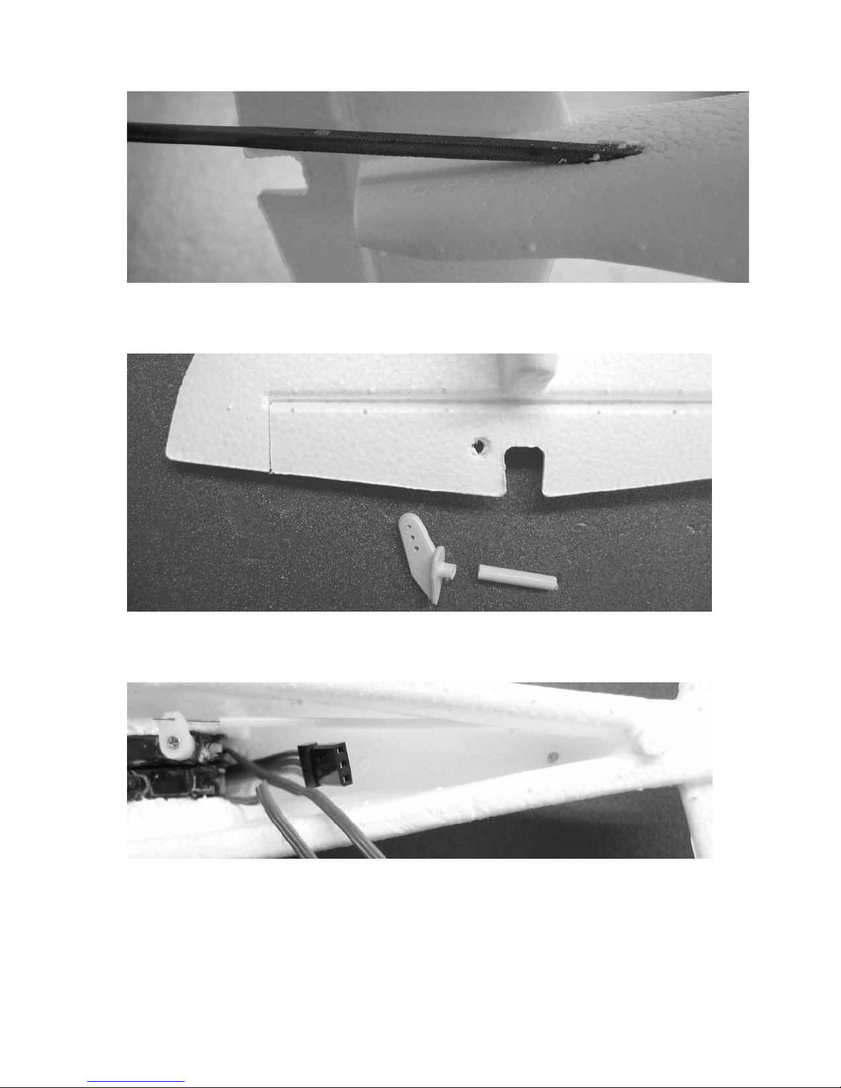
Abb. Nr. 8
Die Abbildung zeigt das Aussparen der Durchführungsbohrung Ø ca. 2
mm für das Bowdenzugaußenrohr (5). Dünne Feile oder Bohrer verwenden.
Abb. Nr. 9 Das Ruderhorn (6) kürzen und gemäß Abbildung einpassen, jedoch noch
nicht einkleben.
Abb. Nr. 10 Die Abbildung zeigt die probeweise eingeschobenen Servos C 100. Der
Servohebel des Höhenruderservos ist gekürzt (Hebellänge 5mm) und das Servo
neutral eingestellt. Vor dem Aufschrauben des Servohebels den Höhenruderzug (7)
einhängen. Den Zug (7) hinten passend abkröpfen und kürzen. Erst, wenn alles
passt, die Teile (5) und (6) einkleben. Achtung, dass kein Klebstoff in den
Bowdenzug gelangt. Das Anschlusskabel des Querruderservos, sowie das
Verlängerungskabel unter den Servos nach hinten führen.
8
Page 9
Abb. Nr. 11 Die Abbildung zeigt die vorbereiteten Einzelteile (8) bis (11) der
Querruderanlenkung. Die Teile (11) werden aus dem Restteil von Zug (7) vorerst mit
etwas Überlänge hergestellt. Die Metallteile gründlich überschleifen.
Abb. Nr. 12 Die Hebelgelenke (10), bestehend aus Schrumpfschlauch werden per
Heißluftföhn in Gebrauchslage eingeschrumpft. In der Rumpfseitenwand die
Öffnungen für die Querruderhebel aussparen und die Anlenkungen probeweise
einsetzen.
Abb. Nr. 13 Für das Einkleben der Anlenkhebel (8) und (9) sollte eine weitere
Person behilflich sein.
9
Page 10

10
Das Alurohr bei genau senkrecht nach unten zeigenden Hebeln gegen das
Querruder drücken und mit einem kleinsten Tropfen Sekundenklebstoff (am äußeren
Ende des Alurohres) aufbringen, dieses mit dem Querruder verkleben. Achtung, es
darf keinesfalls Klebstoff auf das „Querruderscharnier“ gelangen. Die Querruder nun
probeweise bewegen, nötigenfalls die seitlichen Öffnungen im Rumpf noch etwas
vergrößern, sodass die Hebel frei schwenken können.
Abb. Nr. 14 Die Steckverbindung zum Verlängerungskabel schließen, den
Elektromotor und die Steckerverbindung einkleben.
Abb. Nr. 15
Die beiden Querrudergestänge (11) exakt passend abkröpfen und in
den gekürzten (Hebellänge je 8mm), abgeschraubten Servohebel einhängen. Die mit
einer Zugentlastungsschleife versehene Empfängerantenne durch den Rumpfboden
führen. Die Servostecker einstecken und den Empfänger einsetzen. Die Servos mit
Klebstoff fixieren.
Page 11

11
Abb. Nr. 16 Den Rumpfrücken (2) entlang der Markierungslinie durchtrennen.
Abb. Nr. 17 Nach einer Funktionskontrolle der Fernsteuerung kann nun der hintere
Teil des Rumpfrückens (2), sowie das Seitenleitwerk (3) aufgeklebt werden.
Achtung, darauf achten, dass das Seitenleitwerk in Längsrichtung exakt
ausgerichtet ist.
Page 12

12
Abb. Nr. 18 Den Magnet (12) und den Dübel (13) einkleben.
Abb. Nr. 19 Die Einzelteile des Fahrwerks, die Radverkleidungen sind bereits
verklebt.
Abb. Nr. 20 Für das Spornrad (16) eine Mulde aussparen und das Rad einkleben.
Page 13

13
Abb. Nr. 21 Den gesamten Fahrwerksbügel (14) gründlich überschleifen. Die Enden
des Fahrwerkbügels exakt durch die Radverkleidungen stecken.
Abb. Nr. 22 Beim Verkleben darauf achten, dass kein Klebstoff in die Radnabe
gelangt. Das bestückte Fahrwerk anschließend exakt ausgerichtet unter den Rumpf
kleben. Die Verkleidungen (17) ablängen und einpassen, auf der Unterseite eine Nut
für den Fahrwerksdraht einschneiden. Die Verkleidungen nun stromlinienförmig
profilieren und einkleben.
Page 14
14
Abb. Nr. 23 Die Abbildung zeigt das fertig eingeklebte Hauptfahrwerk, das mit nur 3
Gramm Gesamtgewicht sehr leicht ist und auf einer glatten Landebahn seine
Funktion optimal erfüllt. Es muss klar sein, dass auf einer Graspiste wegen der
geringen Größe kein Abrollverhalten erwartet werden kann.
Abb. Nr. 24 Die Kabinenhaube mit einem Faserstift schwärzen, ebenso die
Kühllufteinlässe, entsprechend der Abbildung auf dem Verpackungskarton.
Page 15

15
Abb. Nr. 24 Das komplette Modell nun vorsichtig überschleifen, den Schleifstaub
entfernen. Die einzelnen Dekorelemente ausschneiden und aufkleben. Die Ruder mit
schwarzen Linien hervorheben.
Abb. Nr. 25 Die Abbildung zeigt die eingesetzte 2-zellige LiPo Batterie. Bei dieser
Batterieposition soll der Scherpunkt im Bereich von 30 bis 35 mm, gemessen von
der Tragflächenvorderkante, liegen. Wird eine 3-zellige Batterie eingesetzt, diese
nach hinten verschieben, sodass der Schwerpunkt im angegebenen Bereich liegt.
Achtung, das Einschalten der RC Empfangsanlage erfolgt bei dem PICO 8
Drehzahlregler durch das schließen der BEC Steckverbindung, den
Gassteuerhebel des Senders vorher in die gewünschte „Aus“-Position stellen.
Die Ruderausschläge stimmen bei den vorgegebenen Hebellängen bei 100%
Servoausschlag. Der Höhenruderausschlag beträgt 3 mm nach oben und unten,
außen gemessen, der Querruderausschlag jeweils 6 mm, innen gemessen.
Page 16

16
Starten Sie das Modell per Handstart mit viel Schwung ca. 20° nach oben genau
Abmessung in mm
gegen die Windrichtung. Sofern schwacher bis mittelstarker Wind weht, erleichtert
dies den Start und die Landung.
Graupner Modellbau wünscht schöne Flüge mit dem Flugmodell >NEMESIS<
Abb. Nr. 26 Das fertige Modell passt in den Verpackungskarton und lässt sich darin
optimal transportieren und aufbewahren.
Stückliste NEMESIS
Teil-
Benennung An-
Nr.
1 Rumpf 1 Hartschaum Fertigteil
2 Rumpfabdeckung 1 Hartschaum Fertigteil
3 Seitenleitwerk 1 Hartschaum Fertigteil
4 Radverkleidung 1 Paar Hartschaum Fertigteil
5 Bowdenzugaußenrohr 1 Kunststoff Ø 1,9/0,9x110
6 Ruderhorn 1 Kunststoff Fertigteil
7 Höhenruderzug 1 Stahl Ø 0,5x140
8 Querruderhebel links 1 Aluminium Ø 2x65
9 Querruderhebel rechts 1 Aluminium Ø 2x70
10 Hebelgelenk 2 Kunststoff Ø 2,2x22
11 Querrudergestänge 2 Stahl Ø 0,5x55
12 Magnet 1 NdFeB 20x4x1,8
13 Dübel 1 Buche Ø 4x25
14 Fahrwerksbügel 1 Federstahl Fertigteil Ø 0,8
15 Hauptrad 2 Kunststoff Fertigteil Ø 20
16 Spornrad 1 Kunststoff Fertigteil Ø 8
17 Strebenverkleidung 2 Depron 28x13x3
18 Dekorelement 34 Klebefolie Zuschnitt
Ersatzteil (nicht enthalten)
Dekorbogen Best.-Nr. 6288.14
zahl
Werkstoff
Page 17

to Order No.
Building instructions
6288
NEMESIS
Please read and observe the following safety notes.
If you ever dispose of the model, be sure to pass on these safety notes to the new owner so that he
can refer to them.
Safety notes
Be sure to read right through the instructions covering assembly and operation of your model
before you attempt to operate it for the first time. You alone are responsible for the safe
operation of your radio-controlled model. Young people should only be permitted to operate
this model under the instruction and supervision of an adult who is aware of the hazards
involved in this activity.
In legal terms our models are classed as aircraft, and as such are subject to legal regulations
and restrictions which must be observed. Our brochure “Modellflugrecht” (Model Flying Law)
is available under Order No. 8034.01, and contains a summary of all these rules. Your local
model shop should have a copy which you can read. There are also Post Office regulations
concerning your radio control system, and these must be observed at all times. Refer to your
RC system instructions for more details.
Be sure to use only those parts included in the kit, together with other genuine Graupner
accessories and replacement parts as recommended expressly by us. Even if you change a
single component you can no longer be sure that the system will work reliably, and such
changes also invalidate your guarantee.
Avoid short-circuits and reversed polarity.
The high energy density of rechargeable batteries involves a risk of explosion and fire.
A radio-controlled model aircraft can only work properly and fulfil your expectations if it is built
very carefully and in accordance with the building instructions. If you wish to avoid injuring
people and damaging property it is essential to be careful and painstaking at all stages of
building and operating your model. Nobody would climb into a full-size glider and try to fly it
without completing a course of training first. Model flying is a skill which has to be learned in
just the same way.
As manufacturers we are not in a position to influence the way you build and operate your RC
model aircraft, and for this reason we deny all liability. All we can do is expressly point out the
hazards.
We suggest that you ask for help from an experienced model flyer, or join a model club or flight
training school. Your local model shop and the specialist magazines are excellent sources of
information. It is always best to join a club and fly at the approved model flying site.
Adhesives contain solvents which may be hazardous to health under certain circumstances.
Read and observe the notes and warnings supplied by the manufacturers of these materials.
The operator of the model must be in full possession of his or her bodily and mental faculties.
As with car driving, operating a model aircraft under the influence of alcohol or drugs is not
permissible under any circumstances.
If there are passers-by or spectators at your flying site, make sure that they are aware of the
dangers inherent in your activity before you start the motor, and insist that they keep a safe
distance away.
1
Page 18

Always keep a safe distance away from people and objects when flying; never fly low over
people’s heads, and never fly directly towards them.
Radio-controlled models should only be flown in “normal” weather conditions, i.e. a
temperature range of -5° C to +35° C. More extreme temperatures can lead to changes in
battery capacity, material characteristics, weakened glued joints and other unwanted effects.
All model flyers should behave in such a way that the danger to people and property is
minimised. Never act in any way which will disturb other flyers and jeopardise safe, orderly
flying at the site.
Don’t operate your model aircraft close to high-tension overhead cables, industrial sites,
residential areas, public roads, school playgrounds, sports grounds etc.
Pre-flight checks
Check that the radio control system works correctly and at full range before every flight: switch
on the transmitter and the receiving system, and extend the transmitter aerial; check that all
the control surfaces are at neutral when the sticks are central, work smoothly and immediately,
and deflect in the correct “sense” relative to the stick movements. Repeat the check with the
motor running, while a friend holds the model for you.
We recommend that you ask an experienced model pilot to help you check the model and
support you the first time you fly this or any other model aircraft.
Don’t ignore our warnings. They refer to materials and situations which, if ignored, can result
in fatal injury or permanent damage.
Propellers and other rotating parts which are powered by a motor represent a permanent
hazard and present a real risk of injury. Don’t touch them with any part of your body. For
example, a propeller spinning at high speed can easily cut your finger badly.
Keep well clear of the rotational plane of the propeller. You never know when some part may
come loose and fly off at high speed, hitting you or anybody else in the vicinity and potentially
causing serious injury. Never touch the revolving propeller with any object.
Ensure that it is impossible for any object to stall or block the propeller.
Every time you intend to operate your model check carefully that it and everything attached to
it (e.g. propeller, RC components etc.) is in good condition and undamaged. If you find a fault,
correct it before you fly the model.
Satisfy yourself that your frequency is vacant before you switch on. Radio interference caused
by unknown sources can occur at any time without warning. If this should happen, your model
will be uncontrollable and completely unpredictable. Never leave your radio control system
unguarded, as other people might pick it up and try to use it.
Do not switch on the electric motor unless you are sure there is nothing in the rotational plane
of the propeller. Never attempt to stop the spinning propeller. Electric motors with the propeller
attached should only be run when firmly mounted.
If you are to fly your model safely and avoid problems it is essential that you are aware of its
position and attitude throughout each flight - so don’t let it fly too far away! If you detect a
control problem or interference during a flight, immediately land the model to prevent a
potential accident. Models must always give way to full-size aircraft. Take-off and landing
strips should be kept free of people and other obstacles.
Your RC system can only work reliably if the batteries are kept fully charged.
Never use batteries which are hot, faulty or damaged. Heed the instructions provided by the
battery manufacturer at all times.
2
Page 19

Before each flight check that all functions on the model aircraft are working correctly, and that
the radio control system is in good order and operating at full range.
Note that the motor control function on the transmitter must always be moved to the OFF
position as the first stage in preparing for a flight. To avoid the danger of the electric motor
bursting into life unexpectedly, always switch on the transmitter first, and only then the
receiving system. The opposite applies at the end of a flight: always switch off the receiving
system first, and finally the transmitter.
Check that the control surfaces follow the movement of the transmitter sticks.
After each session remove all the batteries from the model and store them in a discharged
state at a temperature of about +5° C to +25° C. They should be kept out of the reach of
children at all times.
Please don’t misunderstand the purpose of these notes. We only want to make you aware of
the many dangers and hazards which can arise if you work carelessly or irresponsibly. If you
take reasonable care, model flying is a highly creative, instructive, enjoyable and relaxing
pastime.
Liability exclusion
We, as manufacturers, have no control over the way you build and operate your RC model
aircraft, nor how you install, operate and maintain the associated radio control equipment For
this reason the Graupner company is obliged to deny all liability for loss, damage or costs
which are incurred due to the incompetent or incorrect use and operation of our products, or
which are connected with such operation in any way.
Unless otherwise prescribed by binding law, the obligation of the Graupner company to pay
compensation, regardless of the legal argument employed, is limited to the invoice value of
that quantity of Graupner products which was immediately and directly involved in the event
which caused the damage. This does not apply if Graupner is found to be subject to unlimited
liability according to binding legal regulation on account of deliberate or gross negligence.
Introduction
The NEMESIS is an extremely unusual electric-powered RC model aircraft which will give hours of
pleasure to any experienced modeller. Please note that this model is not suitable for beginners. The kit
is highly pre-fabricated, but the work you have to carry out is important; the model will only fly well if
you complete your tasks carefully and accurately.
For safety reasons the model should only be fitted out with the accessories listed in the catalogue and
in these instructions. The maximum all-up weight is 130 g, and this must not be exceeded.
Electric power system and accessories
Electric motor Propeller Precision spinner Flight battery Speed controller
Order No. Order No. Order No. Order No. Order No.
SPEED 250 CAM SPEED 20 mm Ø 2-LiPo 240 PICO 8
7.2 V PROP 10 x 8 cm 6033.22 7.4 V / 0.24 Ah 7171
6374 1361.10.8 7600.2
RC system
For this model you require an FM radio control system such as the X-306 to mc-24. For more
information on RC accessories please refer to the main FS catalogue.
Fig. 1
X-306 FM 35 with two additional C 100 servos and XP 10FM receiver
The following RC accessories are required to operate the model:
1 X-306 FM 35 FM radio control system Order No. 4708
2 C 100 servos Order No. 5105
Accessories
TURBOMAT 6 PLUS charger (for transmitter only!) Order No. 6248
Dry cells for transmitter (8 required) Order No. 98843
Transmitter charge lead Order No. 3423
LiPo Charger 4 (only for LiPo battery, Order No. 7600.2) Order No. 6437
Servo extension lead, 100 mm Order No. 3935.11
3
Page 20

Tools and adhesives
Balsa knife Order No. 980
Screwdriver Order No. 810
Allen key, 1.5 mm A/F Order No. 5735.1,5
PICO 30TS fine-tip soldering iron Order No. 826
Electronic grade solder Order No. 1176.1
Styrofoam cyano-acrylate (“foam cyano”) Order No. 5820
Cyano-acrylate activator (“cyano kicker”) Order No. 953.150
400-grit wet-and-dry abrasive paper Order No. 700.2
Heat gun
Black felt-tip pen
Side cutters
Mini flat-nose pliers
Paper scissors
Building instructions
Caution: the styrofoam components must not be allowed to come into contact with UHU hart,
UHU acrylit or similar adhesives, as they will attack and destroy the high-density foam.
Styrofoam is also damaged by temperatures above 60°C.
The styrofoam parts are extremely vulnerable to damage from sharp objects, and easily pick up dents.
You can avoid this by keeping your work surface clean and smooth when assembling the model, or by
working on a layer of foam. Use foam cyano as adhesive for this model. Always use the adhesive
sparingly to save weight. Take particular care to avoid excess glue getting onto the surfaces of the
model.
Fig. 2
The moulding process leaves excess material at the edges of the wing and fuselage (1). The
first step is to cut away this material.
Fig. 3
Use a razor saw to cut slots at both ends of the ailerons and elevator to release the control
surfaces, working along the lines marked on the underside. Carefully “ease” the hinges by deflecting
the control surfaces up and down; they need to move freely through a range of about 10° either side of
centre
Fig. 4
Cut a through-hole below the main “wing joiner” in the fuselage.
Fig. 5
Cut out the cooling opening for the SPEED 250 electric motor, and trim the original air intake to
the shape shown in the picture.
Fig. 6. The capacitors required to suppress the electric motor are supplied with the motor and speed
controller; they can now be soldered to the motor in the arrangement shown To ensure sound
soldered joints, sand and clean the motor can thoroughly before applying the iron.
Fig. 7 Fit the propeller and spinner on the motor, and solder the speed controller to the motor
terminals as shown in the picture.
(+) wire to the motor terminal marked with a red dot.
The 100 mm servo extension lead is required to extend the speed controller cable to reach the
receiver.
Special note if using the X-306 transmitter: connect the aileron servo to receiver socket I, the elevator
servo to socket II, the speed controller to socket III. Be sure to check the working systems before
installing the receiver in the fuselage.
Fig. 8
The photograph shows the method of cutting the tunnel through the foam for the snake outer
sleeve (5). The hole should be about 2 mm Ø. Use a thin file or drill for this.
Fig. 9 Shorten the spigot of the elevator horn as shown. Cut a hole for it in the elevator, but do not
glue it in place at this stage.
Fig. 10
servo output arm has been cut down to a lever length of 5 mm, and the servo has been set to neutral
(centre). The elevator pushrod (7) should be connected before the servo output arm and its retaining
screw are fitted Bend the pushrod (7) at right-angles at the horn, and cut off the excess length. When
The photo shows the two C 100 servos, temporarily installed in the fuselage. The elevator
Caution: take care to maintain correct polarity. Solder the white
4
Page 21

you are satisfied that the elevator control system works properly, glue the snake outer sleeve (5) and
the elevator horn (6) in place. Caution: don’t let glue run inside the snake outer. Run the aileron servo
lead and the extension lead to the rear under the servos.
Fig. 11
The picture shows the prepared parts (8) to (11) which form the aileron torque rod linkage. The
pushrods (11) are cut from the remainder of the elevator pushrod (7), leaving them overlength initially.
Sand the metal parts thoroughly.
Fig. 12
The torque rod links (10) consist of pieces of heat-shrink sleeve Position them as shown, and
shrink them onto the metal parts using a heat-gun. Cut openings for the torque rods in the fuselage
sides, and check that the rod assemblies fit in the correct position.
Fig. 13
A second pair of hands is useful for the next stage: gluing the torque rods (8) and (9) in place.
Press the aluminium tube (the torque rod) against the aileron, with the angled end (inside the
fuselage) pointing vertically down, and apply a tiny drop of glue to the outboard end of the aluminium
tube to glue it to the aileron only. Take care! don’t allow glue to get onto the “aileron hinge” area. Move
the aileron up and down, and open up the side openings in the fuselage if necessary in order to
provide clearance for the movement of the torque rod. Repeat the procedure with the second aileron
torque rod.
Fig. 14
Connect the speed controller to the servo extension lead, and glue the electric motor and the
extension lead connector in the fuselage as shown.
Fig. 15
Mark the point where the two aileron pushrods (11) cross the servo output arm linkage holes,
and bend the rods at 90° at exactly the marked points. Cut down the output lever on the aileron servo
(lever length 8 mm each side), and connect the pushrods to the output arms. Tie a loop in the receiver
aerial to act as a strain relief, and thread the aerial through the bottom of the fuselage. Connect the
cables to the receiver and install the receiver in the fuselage. Secure the servos with a little glue.
Fig. 16
Cut through the fuselage turtle deck (2) along the marked line.
Fig. 17
Check that the radio control system works correctly, then glue the rear part of the turtle deck
(2) and the fin (3) to the fuselage.
to the fuselage centreline.
Fig. 18
Glue the magnet (12) and the dowel (13) in the forward (canopy) section.
Fig. 19
This picture shows the undercarriage components; the halves of the wheel spats have already
been joined.
Fig. 20
Cut a recess for the tail wheel (16) and glue the wheel in it.
Fig. 21 Sand the whole of the steel wire undercarriage unit (14) to provide a mechanical “key” for the
adhesive. Fit the wheels and wheel spats on the wheel axles, pushing the axles through the spats
exactly at right-angles.
Fig. 22 Glue the spats to the wire, taking care that no glue gets into the wheel hubs. Check that the
completed undercarriage is an accurate fit in the underside of the fuselage, and glue it in place. Cut
the leg fairings (17) accurately to length, trim them to fit, and cut a channel in the underside of each to
accommodate the wheel legs. Sand the fairings to a streamlined cross-section and glue them in place.
Fig. 23
weight the assembly is very light, and it works well on a really smooth take-off strip. However, the
small size of the wheels obviously precludes any hope that the model could roll on a grass strip.
Fig. 24
way, as shown in the picture on the kit box lid.
Fig. 24 Carefully sand the whole model smooth, and remove all traces of sanding dust. Cut out the
individual decals and apply them to the model. A black line along the control surface hinge axes
makes them stand out better.
The photograph shows the main undercarriage permanently installed. At 3 grammes total
Colour the canopy area using a black felt-tip pen. Pick out the cooling air intakes in the same
Caution: check carefully that the fin is aligned exactly parallel
5
Page 22

Fig. 25
The photo shows the two-cell Li-Po battery for which the model was designed. With the battery
pack positioned as shown the model should balance at a point 30 to 35 mm back from the wing root
leading edge. If you use a 3-cell battery, it will need to be moved further aft to ensure that the CG is in
the stated range.
Caution: the PICO 8 speed controller has no separate switch, so the receiving system is
switched on when you connect the battery using the BEC connector. It is therefore important
to set the transmitter throttle stick to the “OFF” position before you connect the flight pack.
If you have used the recommended lever lengths, and have left the servo travels at the standard value
(100%), the control surface travels will automatically be correct. Elevator travel should be 3 mm up
and down, measured at the tips. Aileron travel should be 6 mm each way, measured at the inboard
end.
Give the model a powerful hand-launch exactly into wind, with the wings level and the nose inclined up
by about 20°. Launching and landing will be easier if there is a gentle to moderate wind.
All of us at GRAUPNER Modellbau wish you every success and many enjoyable flights with your
NEMESIS.
Fig. 26 The completed model fits in the original kit box, which provides excellent protection for
transport and storage.
Parts List - NEMESIS
Part Description No. Material Dimensions
No. off in mm
1 Fuselage 1 High-density foam Ready made
2 Fuselage turtle deck 1 High-density foam Ready made
3 Fin 1 High-density foam Ready made
4 Wheel spat Pair High-density foam Ready made
5 “Snake” outer sleeve 1 Plastic 1.9 / 0.9 Ø x 110
6 Control surface horn 1 Plastic Ready made
7 Elevator pushrod 1 Steel 0.5 Ø x 140
8 L.H. aileron torque rod 1 Aluminium 2 Ø x 65
9 R.H. aileron torque rod 1 Aluminium 2 Ø x 70
10 Torque rod link 2 Heat-shrink sleeve 2.2 Ø x 22
11 Aileron pushrod 2 Steel 0.5 Ø x 55
12 Magnet 1 NdFeB 20 x 4 x 1.8
13 Dowel 1 Beech 4 Ø x 25
14 Wire undercarriage unit 1 Spring steel Ready made, 0.8 Ø
15 Main wheel 2 Plastic Ready made, 20 Ø
16 Tailwheel 1 Plastic Ready made, 8 Ø
17 Undercarriage leg fairing 2 Depron 28 x 13 x 3
18 Decal 34 Self-adhesive film Sheet
Replacement part
Decal sheet 6288.14
(not included)
GRAUPNER GmbH & Co. KG D-73230 KIRCHHEIM/TECK GERMANY
We reserve the right to introduce modifications. No liability for printing errors.
Id. No. 50414
11/2004
Made in Germany
6
Page 23

pour Réf. N°
6288
Instructions de montage
NEMESIS
Observez impérativement les conseils de sécurité qui vont suivre.
Si le modèle doit être cédé à une autre personne, ces conseils de sécurité devront absolument lui être
remis.
Conseils de sécurité
Avant de tenter la première mise en service, la totalité des instructions de montage et
d'utilisation devra être attentivement lue. Vous êtes seul responsable de la sécurité
d'utilisation de votre modèle R/C.
Il est conseillé aux jeunes modélistes de se faire assister pour la construction et les premiers
vols par un adulte déjà familiarisé avec les particularités et les possibilités de danger
représentés par un modèle volant radiocommandé.
Un modèle réduit volant est comparable à un véritable aéronef pour lequel toutes les
dispositions légales doivent être prises; la possession d'une assurance est obligatoire.
Il conviendra d'utiliser exclusivement les éléments fournis dans la boite de construction ainsi
que les accessoires d'origine Graupner. Si un seul composant de la propulsion électrique est
remplacé, une parfaite sécurité de fonctionnement ne peut plus être assurée et peut entraîner
la perte du bénéfice de la garantie.
Evitez les court-circuits et les inversions de polarité.
La forte énergie emmagasinée par les batteries présente un danger d'explosion et d'incendie.
Un modèle volant ne peut évoluer correctement que s'il a été construit et réglé conformément
aux instructions de montage. Seule une utilisation prudente et responsable évitera de causer
des dommages personnels et matériels. Personne ne peut prétendre prendre place dans un
avion de tourisme et le piloter sans un apprentissage préalable. Il faut aussi apprendre à piloter
un modèle réduit!
Le fabricant n’a cependant aucune possibilité d’influencer la construction et l’utilisation d’un
modèle volant R/C. C’est pourquoi nous ne pouvons qu’avertir sur les dangers représentés en
déclinant toute responsabilité.
Adressez-vous à un modéliste expérimenté, une association ou à une école de pilotage. Vous
pourrez en outre consulter votre revendeur ou la presse spécialisée sur le sujet. Le mieux est
de vous inscrire dans un club d’aéromodélisme pour pouvoir voler sur un terrain autorisé.
Les colles contiennent un solvant qui dans certaines circonstances peut être nocif pour la
santé. Observez impérativement le mode d’emploi et les avertissements du fabricant
correspondant.
L'utilisateur doit être en pleine possession de ses facultés physiques et mentales. Comme
pour la conduite des automobiles, le pilotage d'un modèle réduit sous l'effet de l'alcool ou de la
drogue n'est pas autorisé.
Avant de faire voler votre modèle, informez tous les passants et les spectateurs sur les
possibilités de danger qu'il peut présenter et priez-les de se tenir à une distance de sécurité
suffisante.
Tenez-vous à une distance de sécurité suffisante de personnes ou d'obstacles; ne survolez
jamais de personnes à basse altitude et ne volez jamais dans leur direction.
1
Page 24

Un modèle volant R/C ne doit voler que par des températures extérieures comprises entre – 5°
à + 35°C. Des températures extrêmes peuvent conduire par ex. à une modification de la
capacité des accus, des propriétés des matériaux et de la résistance des collages.
Chaque modéliste doit se comporter de façon à ce que l'ordre et la sécurité publiques, vis-à-vis
des autres personnes et des biens, ainsi que l'activité des autres modélistes ne soient pas mis
en danger, ni perturbés.
Ne faites jamais voler votre modèle à proximité des lignes à haute tension, dans les zones
industrielles, les agglomérations, sur les voies publiques, les places, dans les cours d'école,
les parcs et les aires de jeux, etc…
Vérifications avant le vol :
Vérifiez le fonctionnement correct de l’installation R/C avant chaque vol. Pour cela, mettez
d’abord l’émetteur en contact, ensuite la réception, déployez l’antenne télescopique de
l’émetteur et vérifiez si toutes les gouvernes fonctionnent impeccablement et si elles débattent
dans le bon sens. Répétez cette vérification avec le moteur en marche, en faisant tenir le
modèle par un aide.
Pour les premiers essais d’un modèle volant, il est toujours préférable d’avoir un aide
expérimenté à ses côtés qui vérifiera les réglages et assistera les premiers vols.
Les avertissements donnés devront être impérativement respectés. Leur non-observation peut
conduire à de sérieux dommages et dans les cas extrêmes à des blessures graves.
Les hélices et en général toutes les pièces en rotation entraînées par un moteur présentent un
danger de blessure permanent. Elles ne doivent être touchées par aucune partie du corps. Une
hélice tournant à haut régime peut par ex. couper un doigt!
Ne vous tenez jamais devant ou sur le côté du champ de rotation d'une hélice! Une pièce peut
toujours se détacher et être éjectée à haute vitesse avec une grande énergie et vous touchez
vous-même ou un tiers. Veillez à ce qu'aucun objet quelconque ne vienne en contact avec une
hélice en rotation.
Un risque de blocage d'une hélice par un objet quelconque doit être absolument exclu!
Avant chaque utilisation, contrôlez le modèle et toutes les pièces qui y sont rattachées (par ex.
hélice, éléments R/C, etc…) pour vérifier leur fixation et détecter une possible détérioration. ce
n'est qu'après avoir remédié à tous les défauts éventuels que le modèle sera en ordre de vol.
Assurez-vous que la fréquence que vous utilisez est libre avant de mettre votre émetteur en
contact! Une perturbation peut toujours se produire pour une cause inconnue, sans prévenir!
Le modèle devient alors incontrôlable et livré à lui-même! Ne laissez pas votre émetteur sans
surveillance pour éviter une manipulation par un tiers.
Mettez le moteur électrique en contact que lorsque rien ne se trouve dans le champ de rotation
de l'hélice. Faites tourner le moteur électrique avec l'hélice que lorsqu'il est solidement fixé
dans le modèle.
La position du modèle doit être nettement identifiable durant tout le vol pour garantir un
pilotage sûr. Si vous remarquez l'influence d'une perturbation durant le vol, préparez-vous
immédiatement à atterrir pour des raisons de sécurité. Durant le départ et le processus
d'atterrissage, le terrain doit être libre de toute personne et d'obstacle.
Veillez toujours au bon état de charge des accus, car autrement le parfait fonctionnement de
l'ensemble R/C ne peut être garanti.
N'utilisez jamais de batteries échauffées, devenues défectueuses ou détériorées. Observez les
prescriptions d'utilisation du fabricant des batteries.
2
Page 25

Faites une vérification complète de l'installation R/C et du modèle ainsi qu'un essai de portée
avant chaque séance de vols.
Veillez toujours à ce que l'organe de commande du moteur électrique sur l'émetteur soit placé
sur la position COUPE. Mettez alors toujours d'abord l'émetteur en contact et ensuite la
réception pour empêcher un démarrage incontrôlé du moteur. Coupez ensuite toujours d'abord
la réception, ensuite l'émetteur.
Vérifiez si le sens de déplacement des gouverne correspond à celui des manches de
commande.
Retirez toutes les batteries du modèle après son utilisation et conservez-les sous une
température comprise entre + 5° à + 25° et hors de la portée des enfants.
Ces conseils mettent en évidence la diversité des dangers pouvant résulter d'une manipulation
incorrecte et irresponsable. Leur observation permettra de pratiquer en toute sécurité ce loisir
créatif et éducatif que représente l'aéromodélisme.
Exclusion de responsabilité
Le respect des instructions de montage et d'utilisation relatives au modèle ainsi que
l'installation, l'utilisation et l'entretien des éléments de son équipement ne peuvent pas être
surveillés par la Firme Graupner. C'est pourquoi nous déclinons toute responsabilité
concernent les pertes, les dommages ou les coûts résultants d'une mauvaise utilisation ou
d'un fonctionnement défectueux, ainsi que notre participation aux dédommagements d’une
façon quelconque.
Tant qu'elle n'y a pas été contrainte par le législateur, la responsabilité de la Firme Graupner
pour le dédommagement, quelque soit la raison de droit, se limite à la valeur marchande
d’origine Graupner impliquée dans l’accident. Ceci n’est pas valable dans la mesure où la
Firme Graupner serait contrainte par la législation en vigueur pour une raison de grande
négligence.
Généralités
Le NEMESIS est un extraordinaire modèle R/C à propulsion électrique qui procurera beaucoup de
plaisir à tous les pilotes R/C expérimentés. Ce modèle ne convient pas aux modélistes débutants.
Ce modèle est largement préfabriqué, les stades d’assemblage qui vont être décrits devront
cependant être exécutés avec un grand soin pour garantir les meilleures performances.
Propulsion électrique et accessoires
Moteur électrique
Réf. N°
SPEED 250
7,2 V
6374
Hélice
Réf. N°
CAM SPEED
PROP
10x8 cm
1361.10.8
Cône de précision
Réf. N°
φ 20mm
6033.22
Batterie de propulsion
Réf. N°
2-Li¨Po 240
7,4 V/0,24 Ah
7600.2
Régulateur de vitesse
Réf. N°
PICO 8
7171
Accessoires R/C
Les ensembles R/C FM, comme par ex. X-306 à mc-24, sont exclusivement adaptés pour
l’équipement de ce modèle. D’autres informations sur les accessoires R/C se trouvent dans le
catalogue général FS.
Fig.1
:L’émetteur X-306 FM 35 avec 2 servos supplémentaires C 100 et le récepteur XP 10FM.
Les accessoires suivants sont nécessaires pour l’équipement du modèle :
1 Ensemble R/C X-306 FM 41 * Réf. N°4709.41
2 Servos C 100 Réf. N°5105
* Fréquence autorisée pour la France
3
Page 26

Autres accessoires
Chargeur TURBOMAT 6 PLUS (seulement pour l’émetteur !) Réf. N°6428
Batterie d’émission (8 pces nécessaires) Réf. N°98843
Cordon de charge émetteur RéF. N°3423
Chargeur LiPo 4 (seulement pour la batterie LiPo Réf. N°7600 .2) Réf. N°6437
Cordon de rallonge 100mm Réf. N°3935.11
Outils et colles nécessaires
Couteau à balsa Réf. N°980
Tournevis Réf. N°810
Tournevis six pans SW 1,5 Réf. N°5735.1,5
Fer à souder PICO 30TS Réf. N°826
Soudure pour radio Réf. N°1176.1
Activateur pour colle-seconde Réf. N°953.150
Séchoir électrique
Crayon-feutre noir
Pinces coupantes
Mini-pinces plates
Ciseaux
Instructions de montage
Attention ! Les pièces en Styropor ne devront en aucun cas venir en contact avec les colles
UHU hart, UHU plus acrylit, etc… car ces colles dissolvent la mousse de plastique. En outre,
les pièces en Styropor seront détériorées sous une chaleur supérieure à 60° C.
Les pièces en Styropor sont particulièrement sensibles aux marques laissées par des bords vifs.
Durant les assemblages, travailler toujours sur une surface propre et lisse ou sur une base en
caoutchouc. Utiliser de la colle-seconde pour Styropor. Appliquer généralement la colle avec
parcimonie. Veiller particulièrement à ce des bavures de colle ne coulent pas sur les surfaces du
modèle.
Fig.2
: Séparer d’abord les moulages de fabrication sur l’aile et sur le fuselage (1).
Fig.3
: Sectionner les entailles pour rendre mobiles les volets d’ailerons et la gouverne de profondeur
qui sont marquées à l’intrados. Plier ensuite soigneusement les gouvernes de façon à ce qu’elles
puissent se braquer légèrement sur env. 10° vers le haut et vers le bas.
Fig.4
: Evider une ouverture de passage sous la traverse du longeron.
Fig.5
: Découper l’entrée d’air pour le moteur électrique SPEED 250 et lui donner la forme
correspondante à l’originale.
Fig.6 : Antiparasiter le moteur électrique, souder les condensateurs (fournis avec le moteur et le
régulateur de vitesse) conformément à l’illustration ; limer et nettoyer préalablement les emplacements
de soudure sur le carter.
Fig.7 : Monter l’hélice avec le cône de précision et souder le régulateur de vitesse conformément à
l’illustration.
marquée d’un point rouge
Un cordon de rallonge de 100mm sera nécessaire entre le régulateur de vitesse et le récepteur.
Conseil particulier avec l’utilisation d’un émetteur X-306 : Connecter le servo d’ailerons sur la sortie de
voie I du récepteur, le servo de profondeur sur le sortie II et le régulateur de vitesse sur la sortie III.
Faire absolument un contrôle de fonctionnement avant l’installation du récepteur.
Fig.8
: L’illustration montre le perçage d’un trou de passage d’env. φ 2mm pour la gaine extérieure de
transmission (5)à ; utiliser une lime fine queue de rat ou un foret.
Fig.9
: Raccourcir le guignol de gouverne (6) et l’adapter conformément à l’illustration, mais ne pas
encore le coller.
Attention aux bonnes polarités, souder le fol blanc (+) sur la borne du moteur
.
4
Page 27

Fig.10
: L’illustration montre la mise en place provisoire d’un servo C 100. Le palonnier du servo de
profondeur est raccourci (Bras de levier 5mm) et le servo est réglé au neutre. Connecter la
transmission de profondeur (7) sur le palonnier avant de le monter sur le servo. Contre-couder
l’extrémité arrière de la transmission (7) et la couper de longueur. Lorsque tout est adapté, coller les
pièces (5) et (6). Attention ; Veiller à ce que le la colle ne pénètre pas dans la gaine de la
transmission. Faire passer le cordon du servo d’ailerons ainsi que le cordon de rallonge sous le servo,
vers l’arrière.
Fig.11 : L’illustration montre les différentes pièces (8) à (11) préparées pour les crochets d’ailerons.
Les pièces (11) seront préalablement fabriquées dans la chute de la transmission (7) avec une légère
sur-longueur ; bien dépolir les pièces métalliques.
Fig.12
: Les articulations (10) sont constituées de deux gaines thermo-rétractables rétractées avec un
séchoir électrique sur les crochets et les tringleries d’ailerons. Evider les ouvertures dans les flancs du
fuselage pour les crochets d’ailerons et monter provisoirement ces derniers.
Fig.13 : Un aide sera utile pour le collage des crochets d’ailerons (8) et (9).
Presser les tubes d’aluminium avec le levier orienté exactement verticalement vers le bas contre les
volets d’ailerons et les coller avec ceux-ci en appliquant quelques petites gouttes de colle-seconde
(sur l’extrémité extérieure des tubes d’aluminium). Attention, la colle ne devra en aucun cas couler sur
l’articulation des volets d’ailerons. Vérifier le débattement des volets, agrandir un peu les ouvertures
latérales dans le fuselage si nécessaire de façon à ce que les leviers puissent se déplacer librement.
Fig.14 : Connecter le cordon de rallonge, puis coller le moteur électrique et les connecteurs des
cordons.
Fig.15
: Contre-couder les deux tringleries d’ailerons (11) exactement ajustées et les connecter sur le
palonnier du servo démonté et raccourci (Bras de levier de chaque côté 8mm). Faire passer le fil
d’antenne du récepteur pourvu d’une boucle d’arrêt au travers du fond du fuselage. Connecter la prise
du cordon des servos sur le récepteur et les fixer en place avec de la colle.
Fig.16
: Séparer le dos du fuselage le long de la ligne marquée.
Fig.17
: Après un essai de fonctionnement de l’installation R/C, la partie arrière du dos du fselage (2)
ainsi que la dérive (3) pourront être collés en place.
Attention, veiller à ce que la dérive soit
exactement alignée dans le sens longitudinal.
Fig.18 :
Coller en place l’aimant (12) et le tourillon (13).
Fig.19
: L’illustration montre les différentes pièces du train d’atterrissage ; les carénages de roue sont
déjà collés.
Fig.20
: Evider une cuvette sous l’arrière du fuselage et y coller la roulette de queue (16).
Fig.21 : Dépolir l’ensemble des jambes du train d’atterrissage (14). Introduire les extrémités des
jambes exactement au travers des carénages de roue.
Fig.22 : En collant les jambes sur les carénages, veiller à ce que la colle ne pénètre pas dans le
moyeu des roues. Coller ensuite le train d’atterrissage en l’alignant exactement sous le fuselage.
Couper de longueur les pantalons (17), les ajuster et pratiquer une rainure sur leur face intérieure pour
la jambe du train. Profiler ensuite les pantalons et les coller en place.
Fig.23
: L’illustration montre le train d’atterrissage définitivement collé ; il est très léger avec un poids
total de seulement 3 grammes et il remplira parfaitement sa fonction sur une piste lisse. Il est clair qu’il
ne faut pas attendre un roulement au sol sur une piste en herbe en raison de la faible taille de ce
modèle !
Fig.24
: Noircir la verrière de cabine avec un crayon feutre, de même que l’entrée d’air en se référant
à l’illustration sur le carton d’emballage.
5
Page 28

Fig.25
: Poncer maintenant soigneusement et entièrement le modèle, puis essuyer la poussière.
Découper les différents motifs sur la planche de décoration et les poser. Délimiter le contour de la
gouverne de direction avec des lignes noires.
Fig.26 : L’illustration montre la batterie LiPo à 2 éléments mise en place. Avec cette position de la
batterie, le centre de gravité doit se trouver dans une plage située entre 30 et 35mm, mesurée derrière
le bord d’attaque de l’aile. Si une batterie à 3 éléments est utilisée, celle-ci devra être déplacée vers
l’arrière afin que le centre de gravité se trouve dans la plage indiquée.
Attention, la mise en contact de la réception avec le régulateur de vitesse PICO 8 se fait par le
branchement du connecteur BEC, en conséquence, placer préalablement le manche de
commande des gaz sur la position ‘’Coupé’’ désirée.
Les débattements de gouverne correspondent avec les bras de leviers de palonnier indiqués et une
course des servos sur 100%. Les débattements de la gouverne de profondeur sont de 3mm vers le
haut et vers le bas, mesurés à l’extérieur et les débattements des volets d’aileron de 6mm dans les
deux sens, mesurés de l’intérieur.
Lancer le modèle à la main en l’accompagnant d’une bonne poussée dirigée sur env. 20° vers le haut,
exactement contre la direction du vent. Si le vent est faible ou moyen, le décollage et l’atterrissage
seront facilités.
Graupner-Modélisme vous souhaite de beaux vols avec le modèle NEMESIS !
Fig.27
: Le modèle terminé rentre dans le carton d’emballage et peut être ainsi facilement transporté
et stocké.
Liste des pièces NEMESIS
Pce N° Désignation Qté Matériau Dimensions en mm.
1 Fuselage 1 Mousse dure Pièce finie
2 Dos de fuselage 1 Mousse dure Pièce finie
3 Dérive 1 Mousse dure Pièce finie
4 Carénages de roue 1 Paire Mousse dure Pièces finies
5 Gaine extérieure de transmission 1 Plastique
6 Guignol de gouverne 1 Plastique Pièce finie
7 Transmission de profondeur 1 Acier
8 Crochet d’aileron gauche 1 Aluminium
9 Crochet d’aileron droit 1 Aluminium
10 Articulations 2 Plastique
11 Tringleries d’ailerons 2 Acier
12 Aimant 1 Fer doux 20x4x1,8
13 Tourillon 1 Hêtre
14 Jambes de train d’atterrissage 1 Pce Acier ressort
15 Roues principales 2 Plastique
16 Roulette de queue 1 Plastique
17 Pantalons de train 2 Dépron 28x13x3
18 Motifs de décoration 34 Film adhésif Découpe
Pièce détachée
Planche de décoration Réf. N°6288.14
(Non fournie)
φ 1,9/0,9x110
φ
0,5x140
φ 2x65
φ 2x70
φ
2,2x22
φ 0,5x55
φ 4x25
Pièce finie φ 0,8
Pièces finies φ 20
Pièce finie φ 8
GRAUPNER GmbH & Co. KG D-73230 KIRCHHEIM/TECK, ALLEMAGNE
Sous réserve de modifications ! Nous ne sommes pas responsables d’éventuelles erreurs d’impression ! 11/2004
Fabriqué en Allemagne
6
 Loading...