

Page 1
Appendix
Appendix .................................................................... 220
Declaration of conformity ........................................... 226
Graupner Service Centre .......................................... 227
Warranty certificate .................................................... 227
Before use
We are glad that you have chosen a Graupner mz-18
HoTT or mz-24 HoTT 2.4 GHz remote control system.
This system is extremely versatile and can be used by
both beginners and experts.
Please carefully review this manual to achieve the best
results with your remote control, and especially for safe
flying. If any difficulties arise during use, consult the
manual, contact your dealer, or contact the Graupner
Service Center.
Due to technical changes, the information within this
manual may be changed without prior notification.
Introduction
The Graupner remote-control system can be used to
control airplanes, gliders and helicopter models, and
is the perfect choice for anyone looking for a superior
remote-control system. The HoTT system transmits
a range of real-time data such as the motor speed,
voltage, temperature, warnings programmed by the
user, etc. Such data are for example transmitted directly
from a HoTT-compatible governor without requiring
additional sensors. Of course, these data can also be
transmitted from separately-connectable sensors that
are compatible with the HoTT system.
WARNING:
Read all of the instructions so that you
become familiar with how to operate the
system before you start using it. Misuse can
damage the system, cause property damage and/or
serious injury.
Warning and advisory symbols and their meaning
WARNING:
This symbol indicates subsequent information
that is essential for the user to observe. If
operation of the system and safety of the operator and
third parties cannot be ensured.
NOTE:
damage of every category, a loss of warranty, etc.
these instructions or suggestions are not followed,
damage of every category can result.
period.
these instructions are not followed, the reliable
This symbol indicates subsequent information
that the user must observe. If these
instructions are not followed, it may result in
Without a specific heading, this symbol
indicates subsequent information or
suggestions which the user must follow. If
This symbol indicates instructions and
suggestions of all kinds which the user must
follow.
This symbol indicates instructions on the care
of the device that the user must follow to
P
ensure the device remains useful over a long
Before use
3
Page 2
Safety instructions
Please follow the instructions.
To extend your enjoyment of your model, carefully read
this entire manual and pay special attention to the safety
instructions. You should also register now under https://
www.graupner.de/en/service/product_registration.aspx
to automatically receive latest product information by
e-mail.
If you are a beginner on remote-controlled model
airplanes, ships our cars, contact an experienced model
pilot for their advice.
PROPER USE
NOTE:
This remote-control system mast only be
used for the purpose specified by the
control models without passengers. Any other type
of use is not permitted and may damage the system
and cause significant property damage and/or
personal injury. No warranty or liability is therefore
offered for any improper use not covered by these
provisions.
NOTE:
TROLLED MODELS ARE NOT TOYS.
If improperly used or mishandled by third parties, even
small models can cause significant property damage
and/or personal injury.
control system. These instructions must therefore be
stored in a safe place and passed on to any subsequent
user.
4
manufacturer for operation of remote
THIS SYSTEM IS UNSUITABLE FOR UNSUPERVISED CHILDREN UNDER 14. SAFETY
IS INTENTIONAL, AND REMOTE-CON-
This operating manual is considered part of
the product. It contains important instructions
on how to operate and handle your remote
The warranty expires in case of not observing
the operating and safety instructions.
Safety instructions
Additional instructions and warnings
Technical defects of electrical or mechanical
nature may cause motors to start without
warning, or may generate flying parts which
can cause significant injury to both you and others.
Avoid short-circuits in any circumstance. Shor t-circuits
can destroy parts of the remote control system and
cause serious burns or explosions depending on the
circumstances and the battery charge.
All parts driven by the motor such as air and water
propellers as well as helicopter rotors, exposed gears,
etc. always pose an injury hazard. Never touch these
parts! A fast-rotating propeller can cut off a finger! Make
sure that no other objects come into contact with driven
parts.
Once the battery is connected or the motor is running,
always maintain a safe distance from the hazard area
posed by the propulsion system.
While programming, make sure that a connected
gas motor or electric motor cannot start accidentally.
Disconnect the fuel supply or drive battery beforehand.
Protect all equipment from dust, dirt, moisture and other
foreign parts. All equipment must be protected from
vibration as well as excessive heat or cold. The models
may only be operated remotely in normal outside
temperatures such as from -10°C to +55°C.
Avoid impacts and crushing. Check for damage to
the housing and cables. Devices that become wet or
damaged may not be used anymore even if they dry out.
Only use the components and recommended spare
parts. Always use matching, original Graupner plug-in
connectors of the same design and material.
When running the cables, make sure that they are not
excessively tight, kinked, or severed. A sharp edge may
damage insulation.
Make sure that all of the plug-in connectors are tight.
When disconnecting the plug-in connectors, do not pull
the cables.
No changes may be made to the devices. This will void
permission to use the device along with the warranty. If
appropriate, send the relevant device to the responsible
Graupner service center; see page 227.
Installing the receiver
For flying models, the receiver is installed
behind a strong rib and is protected against
dust and splash water in car and ship models.
When you install your receiver, make sure that it is not
excessively airtight to prevent it from overheating during
operation.
The receiver may not not directly touch the fuselage
or chassis since this may can directly transmit motor
vibration or impact from landing. When installing the
receiver in a model with a gas motor, all of the parts
must be protected to prevent exhaust or oil from
penetrating. This holds true in particular for the ON/OFF
switch that is installed in the shell of the model in most
cases.
Install the receiver so that the connecting cables for
the servos and power supply remain loose, and so that
the receiving antennas are at least 5 cm from all large
metal parts or wires that do not directly originate from
the receiver. This includes carbon fiber parts, servos,
electric motors, fuel pumps, all types of cables, etc. in
addition to metal parts.
It is preferable to install the receiver away from all
other installed parts at an easily accessible location
in the model. Servo cables may not be wound around
antennas or run next to them.
Make sure that the cables cannot shift to lie directly
adjacent to antennas during flight.
Installing the receiver antennas
The receiver and antennas should be as far away as
possible from drives of all kinds. If the tails are made of
carbon fiber, the ends of the antennas should extend
from the fuselage by at least 35 mm. If necessary,
exchange the approx. 145 mm standard antennas of
HoTT receivers with longer antennas.
It does not matter how the antennas are aligned.
However, a vertical installation of a single receiver
antenna in the model is advantageous. In the case of
Page 3
diversity antennas (two antennas), the active end of the
second antenna should be at a 90° angle from the end
of the first antenna, and the distance between the active
ends should ideally be more than 125 mm.
Installing the servos
Always install the servos with the provided rubber
vibration damper as shown in the "Installation
instructions" on page 34. This is the only way to
protect them somewhat from excessive vibration.
Installing the linkages
The linkage must be installed so that it is unhindered
and can move easily. It is particularly important for all a
rudder levers to execute their entire range of movement
without any mechanical restrictions.
To make it possible for running motors to be stopped
at any time, the linkage must be adjusted so that the
carburettor is completely closed when the throttle
control stick and trim are moved into idling end position.
Make sure that no metal parts rub against each other
when moving the rudder, vibrations, rotating parts, etc.
This may produce glitches and malfunction of receiver.
Aligning the transmitter antenna
The field strength emitted from the transmitter antenna
when it is pointing in a straight line is weak. It is therefore incorrect to point the transmitter antenna directly to
the model in the belief that this will increase reception.
When a number of remote control systems are being
used at the same time, the pilots should stand next to
each other in a loose group. Pilots standing away from
the group pose a danger both to their own model and
those of others.
If two or more pilots are using a 2.4 GHz remote control
system and are closer than 5 m from each other, it can
cause interference with the feedback channel, and a
range warning may be generated too early. The pilots
should move away from each other until the range
warning stops.
Checklist before starting
Before turning on the receiver, make sure that the
throttle control stick is at stop/idle.
Always switch on the transmitter before the receiver.
Always switch off the receiver before
switching off the transmitter.
WARNING:
If this sequence is not observed and the
receiver is switched on while the associa-
ted transmitter is "OFF", the receiver can
respond to other transmitters, interference, etc. This
can cause the model to move in an uncontrolled
manner and cause property damage or personal
injury.
When models have a mechanical gyro, the following
holds true:
Before turning on your receiver, make sure that the
motor cannot start unintentionally by disconnecting the
power supply.
When the gyro is running down, it frequently
generates so much voltage that the receiver thinks
that the throttle signals are okay. This can cause the
motor to start unintentionally.
Range and function test
Before every use, check the range and
functioning. Firmly secure the model, and
make sure that no one is nearby.
Perform at least one complete range and function
test on the ground, and run through an entire flight
simulation to determine if there are any problems with
the system or the programming of the model. Follow the
instructions on page 77.
WARNING:
If the range and function test as well as the
flight simulation are not performed
completely and conscientiously,
malfunctions may go unrecognized and
reception may be lost which could cause a loss of
control or even cause the model to crash. This
can result in major property damage and/or
personal injury.
Operating models: Airplane, helicopter, ship and
automobile
WARNING:
•
close to power lines. In addition, never operate
your model close to locks and open nautical
traffic. Do not operate your model on open roads,
highways, paths, public walkways, etc.
• Never switch off the transmitter while operating
the model! If this nonetheless accidentally
happens, do not panic, and wait until the
transmitter display goes dark which indicates
that the transmitter is completely off. This will
take at least 3 seconds. After this time, switch on
the transmitter again. Otherwise, the transmitter
may freeze directly after being switched on,
and you will be unable to control the model.
The transmitter may only be switched on again
after it has been switched off and the described
procedure has been correctly repeated.
Towing
WARNING:
the satellite receiver is an option. Otherwise,
malfunctions from the feedback channel are
possible.
Checking the transmitter and receiver batteries
message " Charge the battery!" appears in the display,
and an acoustic warning sounds.
Regularly check the battery charge, especially of the
receiver battery. Do not wait until the movements of
Never fly the model over the heads
of observers or other pilots. Never
endanger people or animals. Never fly
When operating towed models, maintain a
minimum distance of approximately 50 cm
between the participating receivers. Using
Stop operation and recharge the transmitter
battery at the latest when the
transmitter battery is running low, the
Safety instructions
5
Page 4
the rudder are noticeably slower. Replace damaged
batteries in a timely manner.
Always follow the manufacturers charging instructions.
Do not charge the batteries without monitoring them.
Never attempt to charge dry batteries. An acute
explosion hazard exists.
All batteries must be charged before each use. To
prevent short-circuits, first plug the banana plugs of the
charging cable into the charger (make sure the poles
are correct). Then plug in the charging cable plugs into
the sockets of the transmitter and receiver battery.
If you are not going to use your model for a while,
disconnect all power sources.
Never use rechargeable or replaceable batteries with
damaged, defective or different cell types; that is, a
mixture of old and new cells, or cells by a different
manufacturer.
Capacity and operating time
The following applies to all power sources: The capacity
decreases with each charge. At low temperatures,
the internal resistance increases while the capacity
decreases further. As a result, the battery's ability to
discharge and retain power is reduced.
Frequently charging and/or using battery care programs
can also gradually reduce the capacity. Nevertheless,
check the capacity of power sources at least every
six months, and replace them if their performance is
significantly low.
Only use original Graupner rechargeable batteries!
Suppressing interference in electric motors
All conventional electric motors generate
sparks between the collector and
operation of the remote control system depending on
the type of motor.
Interference-suppressed electric motors are therefore
required for the system to work well. Particularly when
the models have an electric drive, the interference
for each motor must be carefully suppressed. Noise
6
brushes which more or less interfere with the
Safety instructions
filters largely suppress such interference and must be
installed.
Follow the related instructions in the motor's operation
and installation instructions.
Additional details on noise filters can be found in the
main Graupner FS catalogue or on the Internet at www.
graupner.de.
Servo noise filters for extension cables
Order No. 1040
The servo noise filter is required when using longer-
than-usual servo cables. The filter is connected directly
to the receiver output. In critical cases, a second filter
can be placed on the servo.
Electronic speed controllers
The performance of the electric motor determines which
electronic speed controller is used.
To keep the speed controller from overloading or
becoming damaged, the current carrying capacity of
the speed controller should be at least 150 % that of the
maximum stall current of the motor.
Exercise caution with tuning motors, because they only
have a few windings and take several times their rated
current in a stall which can destroy the speed controller.
Electrical ignitions
Ignition systems of gas motors also generate interference that may impair the correct function of remote
controls.
The power supply for electrical ignitions should always
be from a separate source.
Only use interference-suppressed spark plugs and
spark plug connectors and shielded ignition cables.
The receiver should be at a sufficient distance from the
ignition system.
Static energy
WARNING:
Magnetic shock waves generated by
lightning can cause remote control
systems to malfunction even if the
lightning is miles away. If a thunderstorm is
approaching, land your model. Static discharge via
the antenna can also be life-threatening.
Note:
• To satisfy the high-frequency transmission
be maintained between the transmitter antenna and
people. Operation at a closer distance is therefore
not recommended.
• Make sure that no other transmitter is closer than
20 cm to prevent electrical malfunctions and impairment of emissions.
• To operate the remote control system, the country setting must be correct for the transmitter. This
is required to satisfy the various national guidelines
(FCC, ETSI, CE, etc.). Follow the respective instructions for the transmitter and receiver.
• Before each flight, perform at least one complete
range and function test, and run through an entire
flight simulation to determine if there are any problems with the system or the programming of the
model. Follow the instructions on page 77.
• Never program the transmitter or receiver while using the model.
Care
P
Components and accessories
NOTE:
accepted by Firma Graupner|SJ GmbH for suitability,
functioning and safety. If this is done, Graupner|SJ
GmbH will assume responsibility for the product.
However, Graupner|SJ GmbH assumes no liability
requirements of the FCC for mobile transmitters, a distance of 20 cm or more must
Never clean the housing, antenna, etc. with
cleansers, gas, water, etc. Only use a dry, soft
cloth.
As the manufacturer, Graupner|SJ GmbH
recommends only using components and
accessories that have been tested and
Page 5
for products or accessories by other manufacturers
that have not been approved, and is incapable
of evaluating every single third-party product to
determine if it can be used safely.
Disclaimer/damages
This manual is exclusively for information
purposes and is subject to change without
assumes no responsibility or liability for mistakes or
ambiguities that may be found in this manual.
Graupner|SJ GmbH is also incapable of ensuring that
the installation and operation instructions are observed,
and cannot monitor the maintenance of the conditions
and methods for installation, operation, use and
servicing the remote control components. Graupner|SJ
GmbH is also not liable for any loss, damage or costs
arising from, or in anywise associated with, improper
use and operation.
As permitted by law, the responsibility of Graupner|SJ
GmbH shall be restricted to damages, for whatever legal
reason, equivalent to the invoice value of the equipment
of Graupner|SJ GmbH directly involved in the event
leading to the loss. This does not apply in the event of
unlimited liability on the part of Graupner|SJ GmbH due
to intent or gross negligence according to binding law.
page 26 and "Timer" on page 80. The transmitter must also be updated to the most recent software.
Please note, for technical reasons there is no data
recording during playing mp3 files.
In order to be aware of important software updates, you
should therefore register at https://www.graupner.de/en/
service/product_registration.aspx. This will allow you to
automatically receive updates by e-mail.
prior notification. Graupner|SJ GmbH
Furthermore, only those claims can be
reimbursed which are supported by a log
file (see "Collecting/saving data" on
Safety instructions
7
Page 6
Safety instructions and handling guidelines for nickel metal hydride rechargeable
batteries
As is the case with all high-quality products, the following safety instructions and handling guidelines must be
observed to ensure long, trouble-free and safe use.
NOTE:
•
of children.
• Before each use, make sure that the batteries are in
a satisfactory condition. Defective or damaged cells
or batteries may not be used.
• Cells and batteries may only be used in accordance
with the technical specifications for the specific cell
type.
• Batteries and cells may not be heated, burned,
short-circuited or charged with excessive current
or with reversed polarity.
• Batteries from parallel-connected cells, combinations of old and new cells, cells of different
makes, sizes, capacities, manufacturers, brands
or type may not be used.
• Batteries which have been installed in a device
should always be removed when the device is not
being used. Always switch off devices after you have
finished using them to prevent battery drainage. Be
sure to charge the batteries in a timely manner.
• While they are being charged, the batteries must be
placed on a nonflammable, heat-resistant and nonconductive surface. Combustible or highly flammable
objects are to be kept away from the charging area.
• Batteries must be monitored while they are being
charged. The maximum charging current specified
for the respective cell type may not be exceeded.
• If the battery heats up above 60°C while it is being
charged, stop charging and let the battery cool down
to approximately 30°C.
• Do not charge batteries that have already been
charged, are hot, or have not discharged to the
specified level.
Batteries as well as individual cells are not
toys and must be kept from children. They
must therefore be stored out of the reach
• The batteries may not be modified. Do not directly
solder or weld the cells.
• If handled improperly, there is a danger of fire,
explosion, irritation and burns. To extinguish a fire,
use a fire extinguishing blanket, CO2 extinguisher
or sand.
• Leaked electrolyte is caustic and should not be
touched or come into contact with your eyes. In case
of emergency, rinse with a large quantity of water
and then consult a physician.
• The valve openings for the cells should never be
blocked or sealed, for example with solder. When
soldering, the maximum soldering temperature of
220°C should not exceed 20 seconds.
• To avoid deformation, avoid excessive mechanical
pressure.
• If the batteries overheat, proceed as follows:
Disconnect the battery, and place it on a nonflamm-
able surface (such as cement) until it cools down.
Never hold the battery in your hand due to the risk of
explosion.
• Make sure to observe the charging and discharging
instructions.
General instructions
The battery capacity decreases each time it is
charged and discharged. Storage can also
gradually reduce the battery's capacity.
Storage
Batteries may only be stored completely discharged
in dry rooms with an ambient temperature of +5°C to
+25°C.
NOTE:
The cell voltage should not fall below 1.2 V
when stored for a long time. Before being
stored, the battery may have to be charged.
Equalizing the individual battery cells
• To adjust the cells of a new battery to each other,
charge them normally to the maximum charge. As a
rule of thumb, charge empty batteries for 12 hours
with a current which is 1/10 of the rated capacity
(the "1/10 C" method) The cells will then all have the
same charge. The cell charge should be equalized
about every 10th charge in order to extend the life of
the battery.
• If you are able to discharge individual cells, do this
before each charging. Otherwise, the battery pack
should be discharged to 0.9 V per cell. With the fourpack used in the transmitter, this corresponds for
example to a discharge voltage of 3.6 V.
Charging
While charging, the specified current, charging time and
temperature range should be observed under constant
monitoring. If you do not have a suitable fast charger
that allows the charging current to be precisely adjusted,
charge the battery the usual way using the 1/10 C
method (see the example above).
Given the different charges of the cell, transmitter
batteries should be charged using the 1/10 C
method whenever possible. The charging current
should never exceed the maximum permissible level
indicated in the transmitter instructions.
Fast charging
If your charger has this option, set the delta peak cutoff
voltage to 5 mV per cell. Most chargers are permanently
set to 15 … 20 mV per cell and can therefore be used
for both NiCd batteries as well as NiMH batteries. In
case of doubt, consult the operating instructions or the
dealer to determine whether your device can handle
NiMH batteries. In case of doubt, charge your batteries
with one-half the indicated maximum charging current.
Discharging
All of the batteries that are sold by Graupner and GMRacing can handle a maximum continuous charging
current of 6… 13 C depending on the battery type (refer
to the manufacturer's specifications). The battery life
decreases as the continuous current load increases.
Reflex charging as well as charging/discharging pro-
Safety instructions
8
Page 7

grams unnecessarily shorten the life of batteries and are
only suitable for checking the battery quality or restoring
old cells. It is likewise not recommendable to charge and
discharge a battery before a single use unless you want
to check the battery's quality.
Instructions on the mz-18 HoTT remote control set
Order No. S1005
The respective Transmitter set is equipped
with a four-cell NiMH transmitter battery
default undervoltage limit of 4.8 V, a warning message
appears in the display of the transmitter.
(subject to change). After reaching the factory
Safety instructions
9
Page 8

Safety instructions and handling guidelines for lithium-ion and lithium polymer
rechargeable batteries
As is the case with all high-quality products, the following safety instructions and handling guidelines must be
observed to ensure long, trouble-free and safe use of
lithium-ion and polymer batteries.
Lithium-ion/lithium polymer batteries require special
treatment. This is true when charging, discharging,
storing and all other types of handling. Observe the
following specifications:
Special instructions on charging Graupner
lithium-ion/lithium polymer batteries
NOTE:
•
voided upon incorrect charging or discharging.
• Only use the approved chargers with the associated
charging cables to charge lithium-ion/lithium polymer
batteries. Any alterations to the charger or charging
cables can cause serious damage.
• The maximum charging capacity must be limited to a
factor of 1.05 of the battery capacity.
Example: 700 mAh battery = 735 mAh max. charging
capacity
• To charge and discharge lithium-ion/lithium polymer
batteries, only use the plug-in charger in the set,
or the specially designed charger/dischargers by
Graupner, see page 16 or listed at www.graupner.
de.
• Make sure that the number of cells, charging cutoff
and discharging cutoff voltage are set correctly.
Refer to the operating instructions of your charger/
discharger.
• Under these prerequisites, Graupner lithium-ion/
lithium polymer batteries can be charged with a
maximum 2 C (1 C corresponds to the cell capacity)
charging current. Starting at a maximum 4.2 V per
cell, continue charging at a constant 4.2 V per cell
until the charging current falls below 0.1… 0.2 A.
• Do not charge with more than 4.20 V per cell. This
10
Since Graupner|SJ GmbH is unable to
monitor whether the batteries are correctly
charged and discharged, all warranties are
Safety and handling instructions for lithium-ion/lithium polymer batteries
would permanently damage the cell and may cause
a fire. To keep from overcharging individual cells
within the pack, set the cutoff voltage between 4.10
… 4.15 V per cell in order to extend the battery life.
• The permissible temperature range for charging and
discharging lithium-ion/lithium polymer batteries is
0 … +50 °C.
• Batteries as well as individual cells are no toys and
must be kept from children. They must therefore be
stored out of the reach of children.
• Keep batteries away from infants and small children.
If a battery is swallowed, immediately consult a
physician or go to an emergency room.
• Never place a battery in a microwave or under
pressure. This may cause smoke, fire or an
explosion.
• Do not disassemble lithium-ion/lithium polymer
batteries. Disassembling a battery can cause internal
short-circuits. This same results in the release of gas,
fire and explosion, or other problems.
• The electrolyte and electrolyte vapours within
lithium-ion/lithium polymer batteries are hazardous
to health. Avoid direct contact with electrolytes. If the
electrolyte comes into contact with your skin, eyes or
other body parts, use a large amount of fresh water
for rinsing and then consult a doctor.
• Before each use, make sure that the batteries are in
a satisfactory condition. Defective or damaged cells
or batteries may not be used.
• Cells and batteries may only be used in accordance
with the technical specifications for the specific cell
type.
• Batteries and cells may not be heated, burned,
short-circuited or charged with excessive current
or with reversed polarity.
If handled improperly, there is a danger of fire,
explosion, irritation and burns. To extinguish
a fire, use a fire extinguishing blanket, CO2
extinguisher or sand.
• If the batteries overheat, proceed as follows:
Disconnect the battery, and place it on a
nonflammable surface (such as cement) until it cools
down. Never hold the battery in your hand due to the
risk of explosion.
• Batteries from parallel-connected cells, combinations of old and new cells, cells of different
makes, sizes, capacities, manufacturers, brands
or type may not be used.
• Batteries which have been installed in a device
should always be removed when the device is not
being used. Always switch off devices after you have
finished using them to prevent battery drainage.
Dead lithium-ion/lithium polymer batteries are
considered defective and may not be reused.
• Be sure to charge the batteries in a timely manner.
While they are being charged, the batteries must be
placed on a nonflammable, heat-resistant and nonconductive surface. Combustible or highly flammable
objects are to be kept away from the charging area.
• Batteries must be monitored while they are being
charged. The maximum charging current specified
for the respective cell type may not be exceeded.
• You may only charge a pack of series-connected lithium-ion/lithium polymer batteries all at once as long
as the voltage of the individual cells does not deviate
by more than 0.05 V, or if the differences in voltage
are monitored and equalized by a balancer connector using a balancer or equalizer during charging.
The lithium-ion battery in the set comes with a
special safety shut off. The voltage differences
between individual cells are therefore not balanced
by means of the usual balancer plug-in connector.
• If the battery heats up above 60 °C while it is being
charged, stop charging and let the battery cool down
to approximately 30 °C.
• The batteries may not be modified. Do not directly
solder or weld the cells.
• To avoid deformation, avoid excessive mechanical
pressure.
Page 9
• Make sure to observe the charging and discharging
instructions.
Storage
Lithium lithium-ion/lithium polymer cells should
be stored charged with 10-20% of their
lithium-ion/lithium polymer cells must be recharged to
10-20% of the full capacity. Otherwise, the battery will
die during storage and become useless.
Special instructions on discharging Graupner
lithium-ion/lithium polymer batteries
•
• Discharging below 2.5 V per cell will damage the
• The batteries should never be short-circuited. Short-
• The battery's temperature during discharging should
Additional instructions on handling
•
capacity. If the cell voltage falls below 3 V, the
A continuous current of approximately 1 C
does not pose a problem for Graupner
lithium-ion/lithium polymer batteries. If the
current is higher, refer to the instructions in the
catalogue. Bear in mind the maximum load for the
plug-in system (see the maximum discharge current
on battery).
cells and should therefore be avoided at all costs.
circuits generate a very high current which heats
up the cells. This causes a loss of electrolyte, gas
formation or even explosions. Graupner lithium-ion/
lithium polymer batteries should therefore be kept
away from and not touch conductive surfaces due to
the short-circuit hazard.
never exceed +70°C. Otherwise, make sure that the
battery is sufficiently cooled, or reduce the discharge
current. The temperature can be easily checked
using the infrared thermometer (order No. 1963).
However, the battery may not be discharged using
the transmitter's charging socket. This socket is not
designed for this purpose.
The battery capacity decreases each time
it is charged and discharged. Charging
when the temperature is too high or too
low can also gradually reduce the battery's capacity.
After 50 cycles, the battery capacity of models is
only 50-80% of that of a new battery due to the
occasionally high discharge current and induction
current of the motor, even when all charging and
discharging instructions have been followed.
• Batteries may only be series-connected or parallelconnected in exceptions since the cell capacity and
charge can differ. The battery packs that we supply
are therefore preferable.
• The connectors of lithium-ion/lithium polymer
batteries are not as robust as other batteries. This
holds true particularly for the plus connector. The
connectors can easily break.
Cell connector
Direct soldering on the battery cells is not
permitted.
The heat from direct soldering can damage
battery components such as the separator or isolator.
Battery connectors should only be created by spot
welding in the factory. If the cable is missing or severed,
have it repaired professionally by the manufacturer or
dealer.
Replacing individual battery cells
Individually battery cells may only be
exchanged by the manufacturer or dealer and
not by the user.
Do not use damaged cells
Damaged cells may not be used.
Indications of damaged cells include damaged
housing packaging, deformed cells, the smell
of electrolyte or leaking electrolyte. The battery may not
be used in these cases.
Damaged or useless cells are considered hazardous
waste and must be disposed of properly.
General warnings
Batteries may not be immersed in liquid such
as tap water, sea water or beverages. Avoid all
contact with liquids of any kind.
Safety and handling instructions for lithium-ion/lithium polymer batteries
Instructions on the mz-24 HoTT remote control set
Order No. S1006
The remote control set comes standard with a
lithium-ion transmitter battery with an
integrated protective circuit (subject to
modification). A warning appears in the transmitter
display after the voltage falls below the default lowvoltage limit of 3.60 V which may be modified by the
user.
11
Page 10
Disposal of used single-use and rechargeable
batteries
According to the Germany Battery Directive,
consumers are bound by law to return all used
single-use and disposable batteries.
They may not be disposed of in household garbage. Old
single-use and rechargeable batteries can be dropped
off without reimbursement at municipal collection
sites, at our sales outlets and wherever single-use or
rechargeable batteries of the relevant type are sold. Old
rechargeable and single-used batteries supplied by us
can also be reswitched postage-paid to the following
address:
Graupner|SJ GmbH
Service: Used batteries
Henriettenstrasse 96
D-73230 Kirchheim unter Teck
Thank you for protecting the environment!
CAUTION:
Damaged batteries may require special
packaging when shipped because they
may be highly toxic!
Environmental protection information
If this symbol is on the product, instructions for use or packaging, it indicates
that the product may not be disposed
with normal household waste once it
has reached the end of its service life. It
must be sent to a recycling collection
point for electrical and electronic
equipment.
Individual markings indicate which materials can be
recycled. By reusing the product, recycling the materials
or recycling used equipment in other ways, you make
an important contribution to protecting the environment.
Any batteries (including rechargeable batteries) must be
removed from the device and disposed of separately at
an appropriate collection point.
If necessary, contact your local authorities to find the
proper disposal site.
Instructions on disposal and environmental protection
12
Page 11
Computer systems for the mz-18 and mz-24 series
two remote control sets with a 2.4 GHz Graupner HoTT system (hopping telemetry transmission)
Common features
• Microcomputer remote control system using the
latest 2.4 GHz Graupner HoTT technology
• Maximum insensitivity to interference from optimized
frequency hopping over a max. 75 channels and a
wide channel spread
• Intelligent data transmission with a correction function
• Ultrafast reaction times by direct data transmission
from the main processor to the 2.4 GHz RF module
with reliable transmission. No additional delays or
rerouting through other processors.
• Bidirectional communication between the transmitter
and receiver
• Extremely fast rebinding even at maximum distances
• Range test and warning function
• Receiver low voltage warning in the transmitter
display
• Extremely wide receiver operating voltage range
from 3.6 V to 8.4 V (fully functional down to 2.5 V)
• Fail Safe
• A host of programming and evaluation functions
shown directly on the transmitter with special
telemetry displays
• All components may be updated which extends
usefulness
• Cutting-edge wireless trainer system for easy
beginner training
• Touch-sensitive coloured TFT display
• Additional side control buttons
• Etc.
mz-18 remote control set, order No. S1005
• Delivered items
mz-18 HoTT transmitter, order No. S1005.en, with
installed fl at NiMH transmitter battery 4NH-2000
RX RTU (subject to modifi cation), plug-in charger
(5.6 V/200 mA), bidirectional Graupner receiver GR-
12L HoTT (order No. S1012) and GR-24 HoTT (order No. 33512), USB adapter/interface (order No.
7168.6) including USB cable and adapter cable (order No. 7168.6S) for receiver updates, carrying strap
and instructions, warranty card and stylus for alternative use of the touch sensitive display
• Individual transmitter features
Max. 9 control channels
30 model memories
2 trimmable control stick systems (controls 1… 4)
1 two-position switch with long handle (S6*)
1 three-position switch with long handle (S3*)
4 three-position switches with short handle (S1*, S4*,
S5* and S7*)
2 one-side, self-neutralizing three-position switches
with long handle (S2* and S8*)
2 rear proportional sliders (SL1* and SL2*)
2 front proportional dials (DV1 and DV2*)
mz-24 remote control set, order No. S1006
• Delivered items
mz-24 HoTT transmitter, order No. S1006.de, with
installed lithium polymer transmitter battery LiPo
1s2p/4000mAh/3.7 V TX (subject to modifi cation),
plug-in charger (4.2 V/500 mA), bidirectional
Graupner receiver GR-12L HoTT (order No. S1012)
and GR-24 HoTT (order No. 33512), USB adapter/
interface (order No. 7168.6) including USB cable
and adapter cable (order No. 7168.6S) for receiver
updates, as well as a micro SD card with adapter
for card readers, carrying strap, carrying case and
instructions, warranty card and stylus for alternative
use of the touch sensitive display
• Individual transmitter features
Max. 12 control channels
30 model memories
Integrated MP3 player
2 trimmable control stick systems (controls 1… 4)
1 two-position switch with long handle (S6*)
1 three-position switch with long handle (S3*)
4 three-position switches with short handle (S1*, S4*,
S5* and S7*)
2 one-side, self-neutralizing three-position switches
with long handle (S2* and S8*)
2 INC/DEC buttons (DT1* and DT2*)
2 rear proportional sliders (SL1* and SL2*)
4 proportional dials (DV1* … DV4*)
* See "Transmitter control elements" on page 18
Description of the transmitter
13
Page 12
Technical data
mz-18 and mz-24 HoTT transmitters
Frequency band 2.4 … 2.4835 GHz
Modulation FHSS
Transmitting power 100 mW EIRP
Control functions mz-18 HoTT:
9 functions of which 4 can be
trimmed
mz-24 HoTT
12 functions of which 4 can be
trimmed
Temperature range -10 … +55 °C
Antenna Can be turned and folded
Operating voltage 3.4 … 6 V
Power
Approximately 540 mA
consumption
Dimension Approx. 194 x 287 x 112 mm
Weight approx. 840 g with transmitter
battery
Description of the transmitter - Technical data
14
GR-12L HoTT receiver order No. S1012
Operating voltage 3.6 … 8.4 V*
Power consumption Approximately 70 mA
Frequency band 2.4 … 2.4835 GHz
Modulation FHSS
Antenna 1 x approx. 145 mm long,
approx. 115 mm
encapsulated and approx.
30 mm active
Pluggable servos 6
Pluggable sensors 1 (instead of servo 5)
Temperature range Approx. -10 ° … +55 °C
Dimension Approx. 36 x 21 x 10 mm
Weight Approx. 7 g
GR-24 HoTT receiver order No. 33512
Operating voltage 3.6 … 8.4 V*
Power consumption Approximately 70 mA
Frequency band 2.4 … 2.4835 GHz
Modulation FHSS
Antenna Diversity antennas,
2 x approx. 145 mm long,
approx. 115 mm
encapsulated and approx.
30 mm active
Pluggable servos 12
Pluggable sensors 1
Temperature range Approx. -10 ° … +55 °C
Dimension Approx. 46 x 31 x 14 mm
Weight Approx. 16 g
Accessories
Order No. Description
1121 Shoulder strap, 20 mm wide
70 Shoulder strap, 30 mm wide
3097 Windshield for manual transmitters
For additional accessories, see the Annex or the
Internet at www.graupner.de You can also contact your
dealer. He would be glad to assist you.
Trainer cable for the HoTT transmitter,
see page 110
Replacement parts
Order No. Description
S8360 HoTT aluminum case for the mz
transmitter
2498.4FBEC 4NH-2000 RX RTU flat
S8345 Lithium-ion 1s2p/4000mAh/3.7 V
33800 HoTT transmitter antenna
* The specified permissible operating voltage
range applies exclusively to the receiver. In this
context, please note that the input voltage for the
receiver is provided unregulated to the servo
connectors; however, the permissible operating voltage
range for most of the servos, speed controllers, gyros, etc.
on the market is only 4.8 to 6 V.
Page 13
General operating instructions
mz-18 and mz-24 HoTT transmitters
Transmitter power supply
The mz-18 HoTT transmitter comes standard with a
rechargeable NiMH battery with 2000 mAh capacity, and
the mz-24 HoTT transmitter comes standard with a
1s2p lithium-ion battery with 4000 mAh capacity (subject
to modifi cation).
The standard battery installed in the
transmitter is uncharged upon delivery.
The transmitter battery voltage should be monitored in
the LCD display during operation. Once the adjustable
voltage in the "battery warning threshold" is reached in
the "Etc.Set" submenu of the system menu, page 202,
a standard 4.8 V (NiMH) for the mz-18 HoTT transmitter
and 3.6 V (lith.) for the mz-24 HoTT transmitter, a
warning beep sounds, and the following window
appears in the display:
BACK
CLR
TX VOLT
4.7V
STRENGTH
000%
ESC CUR.
000.0A
RX VOLT
02
STRENGTH ALARM
00
ESC VOLT
00
AUTO LOAD
ON
00
3.7V
ON
00
00.0V
or:
BACK
CLR
TX VOLT
3.5V
STRENGTH
000%
ESC CUR.
000.0A
RX VOLT
04
STRENGTH ALARM
00
ESC VOLT
00
AUTO LOAD
ON
00
3.7V
ON
00
00.0V
Now at the latest, stop operation and recharge
the transmitter battery.
Note:
•
Make sure that the correct battery type has
been set in the submenu "Etc.Set" of the
system menu, page 202!
• In a special calibration menu that can be opened by
touching the voltage display in the basic display of
the transmitter using a fi nger or the provided stylus,
the real displayed voltage can be fi ne-tuned (see
"Battery warning" on page 202).
The rechargeable NiMh battery of the mz-18 HoTT
transmitter or the 1s2p lithium-ion battery of the mz-24
HoTT transmitter may be charged as described below
using the charging socket on the rear labelled CHARGE
with the provided plug-in charger:
The charging socket comes standard with a protective
diode that protects against polarity reversal. Original
Graupner automatic chargers recognize the battery
charge. Note the setting instructions of the charger
which is used.
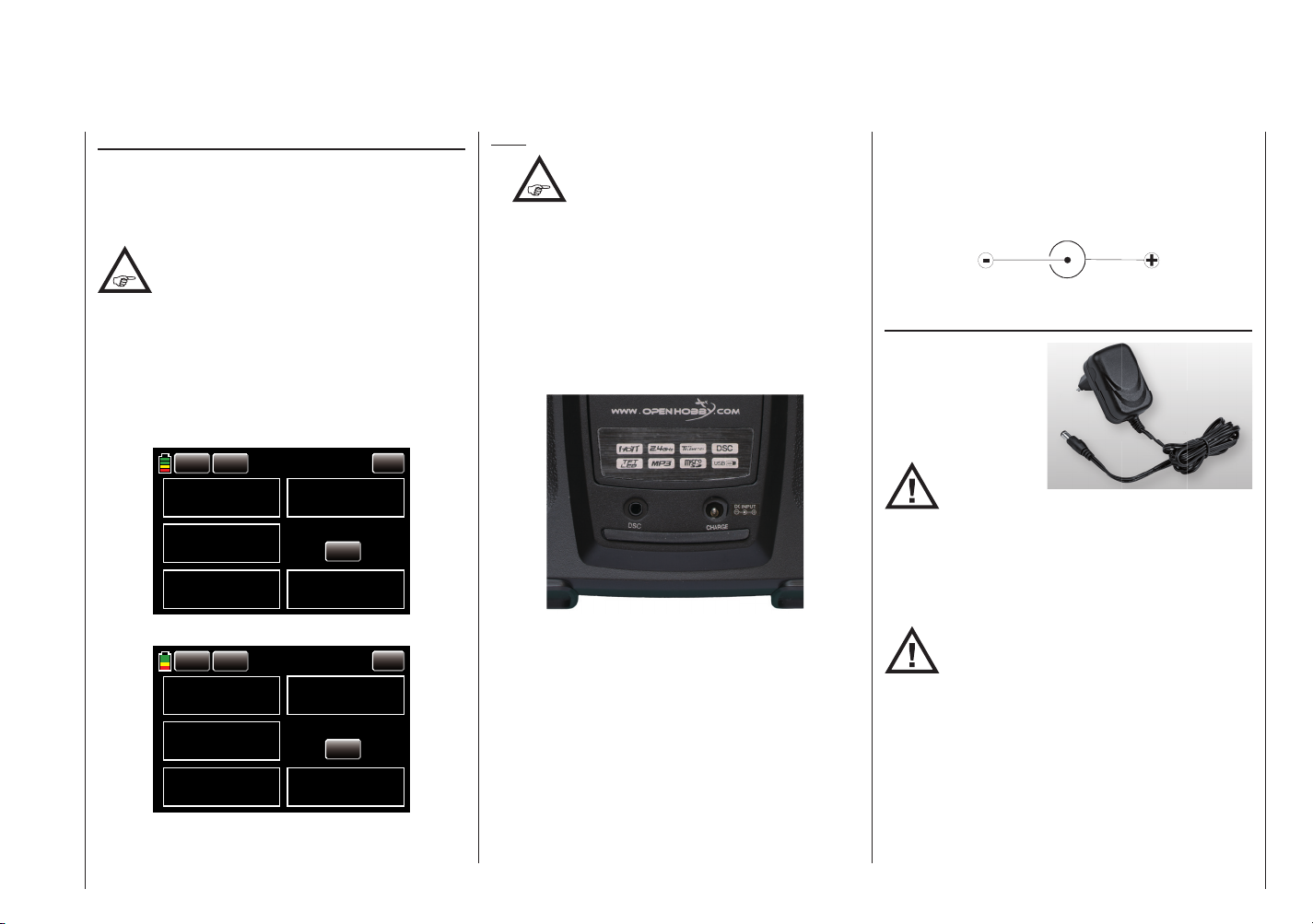
Polarity of the mz charging socket
The charging cables available on the market by other
manufacturers frequently have different polarities. For
this reason, you should only use original Graupner
charging cables with order No. 3022.
Charging the transmitter battery using the plug-in
charger
The charging time with
the plug-in charger
provided in the set may
be up to 15 hours depending on the existing
transmitter battery
charge.
Do not use
plug-in
chargers by other manufacturers or chargers
designed for different battery types. If the output voltage
is too high or the plug polarity is incorrect (see above), it
can cause signifi cant damage. We recommend labelling
the plug-in charger.
Consult the corresponding safety instructions on
pages 4 … 12.
The transmitter must be switched off while
charging. Never switch on the transmitter
when it is connected to the charger. If the
charging is interrupted even for a short time, the
charging voltage can rise enough to immediately
damage the transmitter from overvoltage. You should
therefore make sure that all plug-in connectors are
well-seated.
Description of the transmitter - General operating instructions
15
Page 14
Charging using automatic chargers
000
000
To fast charge the transmitter battery, Graupner automatic chargers can be used. The following table offers a
selection.
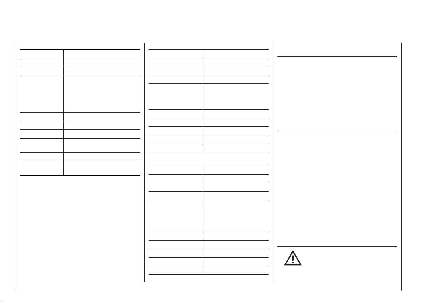
Recommended chargers (accessories)
Suitable for
the following
battery types
Order No.
Name
Connection 230 V AC
Connection 12 V DC
NiCd
NiMH
LiPo
integrated balancer
Lead battery
6411 Ultramat 8 x x x x x
6463 Ultramat 12 plus x x x x x x
6464 Ultramat 14 plus x x x x x x x
6466 Ultra Trio plus 14 x x x x x x x
6468 Ultramat 16S x x x x x x x
6469 Ultra Trio Plus 16 x x x x x x
6470 Ultramat 18 x x x x x x x
6475 Ultra Duo Plus 45 x x x x x x
6478 Ultra Duo Plus 60 x x x x x x x
6480 Ultra Duo Plus 80 x x x x x x
For charging the transmitter battery, the charging cable with
order No. 3022 is required, and for charging the receiver battery,
the charger cable with order No. 3021 is required.
Other chargers as well as details on the listed chargers can be
found in the main Graupner FS catalogue or on the Internet at
www.graupner.de.
First plug the banana plugs of the charging
cable into the charger, and then plug the
other end of the charging cable into
the transmitter charging socket. Never connect the
bare ends of the plugs of a charging cable that is
already connected to the transmitter!
Description of the transmitter - General operating instructions
16
To prevent damage to the transmitter, the charging
current should generally not exceed 1.5 A. Limit the
charge current if necessary.
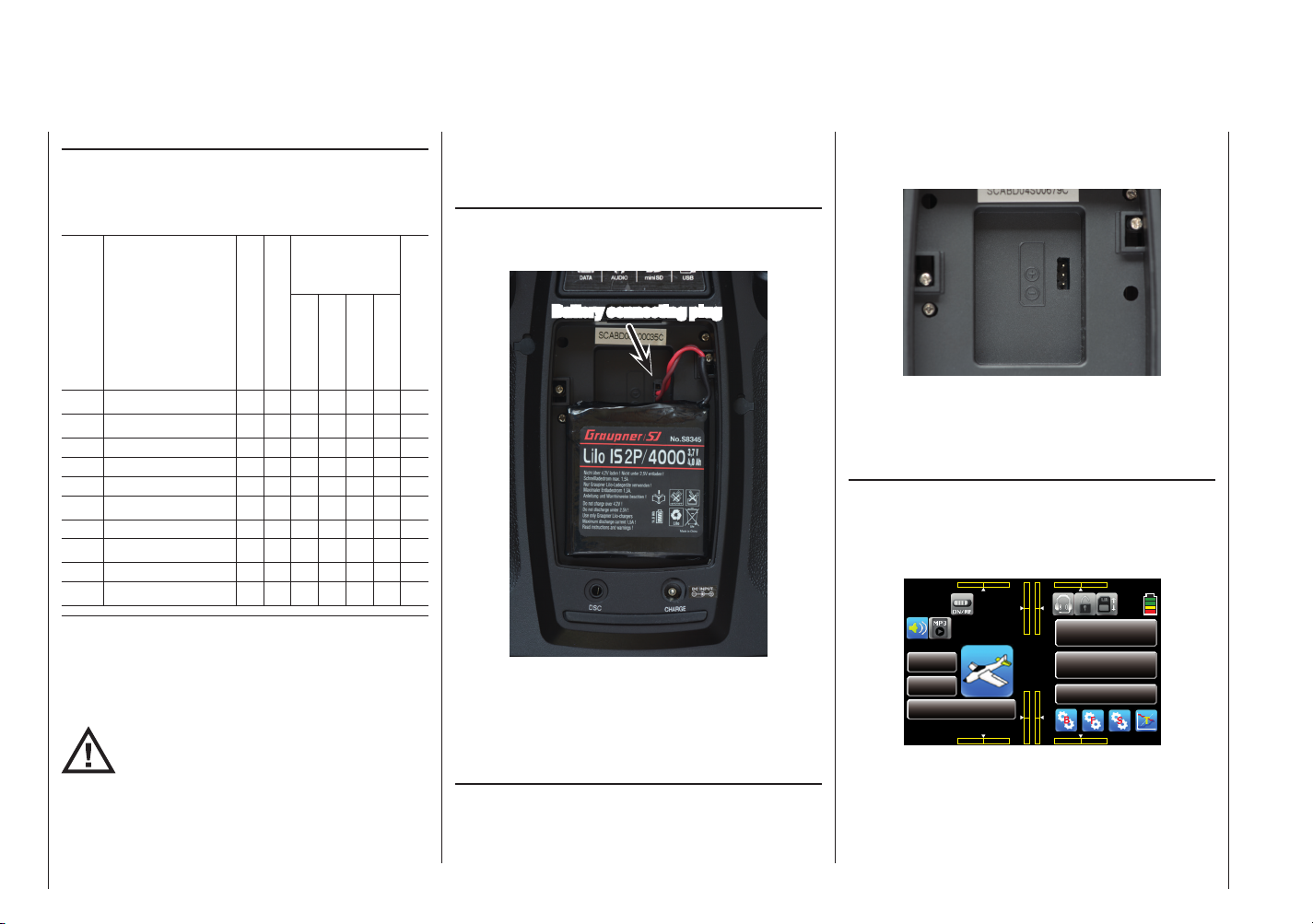
Removing the transmitter battery
To remove the transmitter battery, fi rst remove the cover
of the battery compartment on the back of the transmitter.
Battery connecting plug
Then disconnect the transmitter battery plug by carefully
pulling the supply cable. Then lift the battery and pull it
gently off of the velcro.
(The display shows the battery for the transmitter
mz-24 HoTT.)
Inserting the transmitter battery
The battery connector is protected by two bevelled
edges from polarity reversal when plugging in. The free
socket of the battery connector faces upward at the
bottom of the battery compartment as can be seen in
the following picture. The plus pole (red cable) is in the
middle, and the minus pole (brown or black cable) is on
the side facing the battery.
Never forcefully insert the plug into the socket on the
transmitter board.
Then place the battery into the compartment, and close
the battery cover.
Battery operating time in the bottom left display
The time (green) is automatically reset to 0:00 once the
transmitter battery voltage is recognizably higher than
the most recent voltage after the transmitter is started,
and the display shows the cumulative operating time of
the transmitter since last charging.
000%
0:01:23
M 1
MODEL NAME 1
BATT TIME 00: 01: 23
000 000
mz
000
000
000%
4.2V
000:00.0
000:00.0
NORMAL
Page 15
General charging instructions
•
•
transmitter, the transmitter charging current should
generally not exceed 1.5 A. Limit the charge current
if necessary.
If the transmitter battery is charged with more than
1.5 A, it must be charged outside of the transmitter.
Otherwise, the printed circuit board may be damaged
from overloading the printed connectors and/or
overheating the battery.
• Perform a few test charges to make sure that the
automatic cutoff of automatic chargers works. This is
especially true when you want to use an automatic
charger to charge the NiMH battery which comes
standard in the mz-18 HoTT transmitter, or the
lithium battery which comes standard in the mz-24
HoTT transmitter. Monitor the cutoff behaviour if the
charger that you are using has this option.
• Do not discharge the battery or run battery care
programs using the charging socket. The charging
socket is only for charging.
• Always first connect the charging cable to the charger, and then connect it to the receiver or transmitter
battery. This prevents unintentional short-circuiting
with the bare ends of the charging cable plug.
• If the battery becomes hot, check the battery and
exchange it or reduce the charging current.
• Do not charge the batteries without monitoring
them.
• Follow the safety instructions and handling
guidelines starting page 4.
Follow the charging instructions of the
charger manufacturer and battery
manufacturer.
Do not exceed the maximum permissible
charging current of the battery
manufacturer. To prevent damage to the
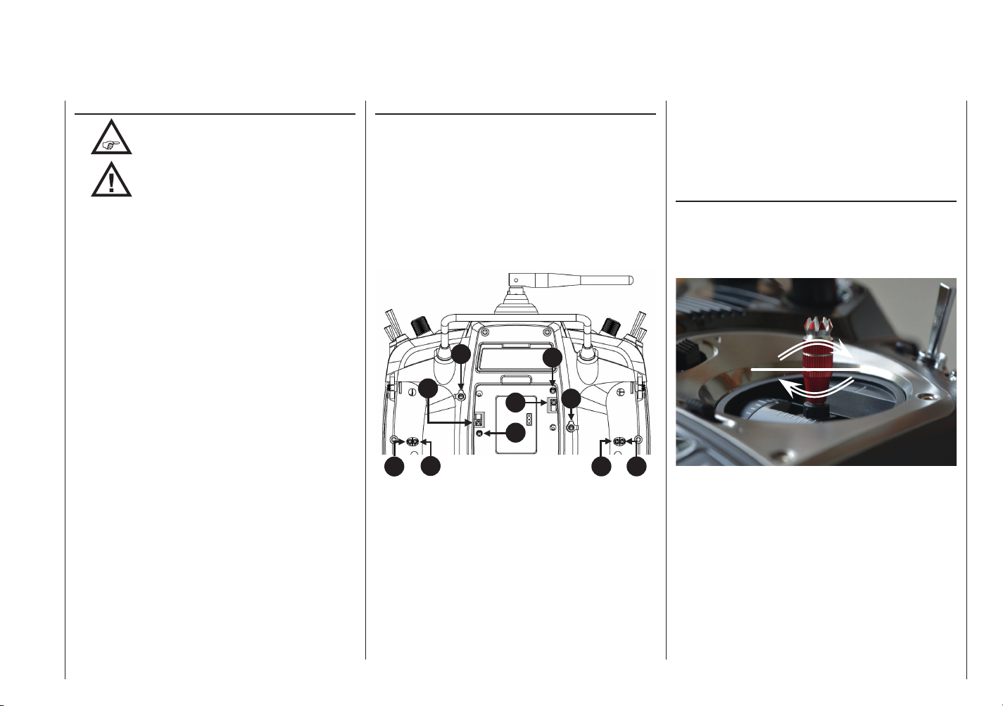
Adjusting the control sticks
Both the left and right control sticks can optionally be
set from neutralizing to non-neutralizing and vice versa.
The resetting force on the control sticks can be set to
the pilot's preferences. The related adjusting system
is on the back of the transmitter in the battery compartment, under the rubber covers, and under the side
grips attached with double-sided adhesive tape (see the
marks in the following picture). Make the desired adjustment by turning the relevant setscrew using a Phillips
or standard screwdriver. Hold the control stick tight as a
precaution:
4
3
1 2
• 1 and 2 / 9 and 10
Adjust the braking force with the outermost of the
two screws, and adjust the strength of the control
stick ratchet using the innermost screw.
• 4 and 5 / 7 and 8
Adjust the return force of the control direction by
turning the relevant setscrew using a Phillips or
standard screwdriver.
7
6
5
8
9 10
• 3 and 6
To change the standard setting of the left and right
control sticks, turn the screw toward the inside of the
transmitter until the relevant control stick can move
freely from stop to stop, or turn it outward until the
control stick resets itself independently.
Adjusting the length of the control sticks
Both control sticks can be gradually adjusted over
approximately 8 mm to adapt the transmitter control to
the pilot's preferences.
Hold down the bottom half of the knurled grip, and
loosen the screwed connection by turning the top part:
You can now lengthen or shorten the control stick by
screwing it up or down. Then clamp the top and bottom
part of the grip by rotating them against each other.
Description of the transmitter - General operating instructions
17
Page 16
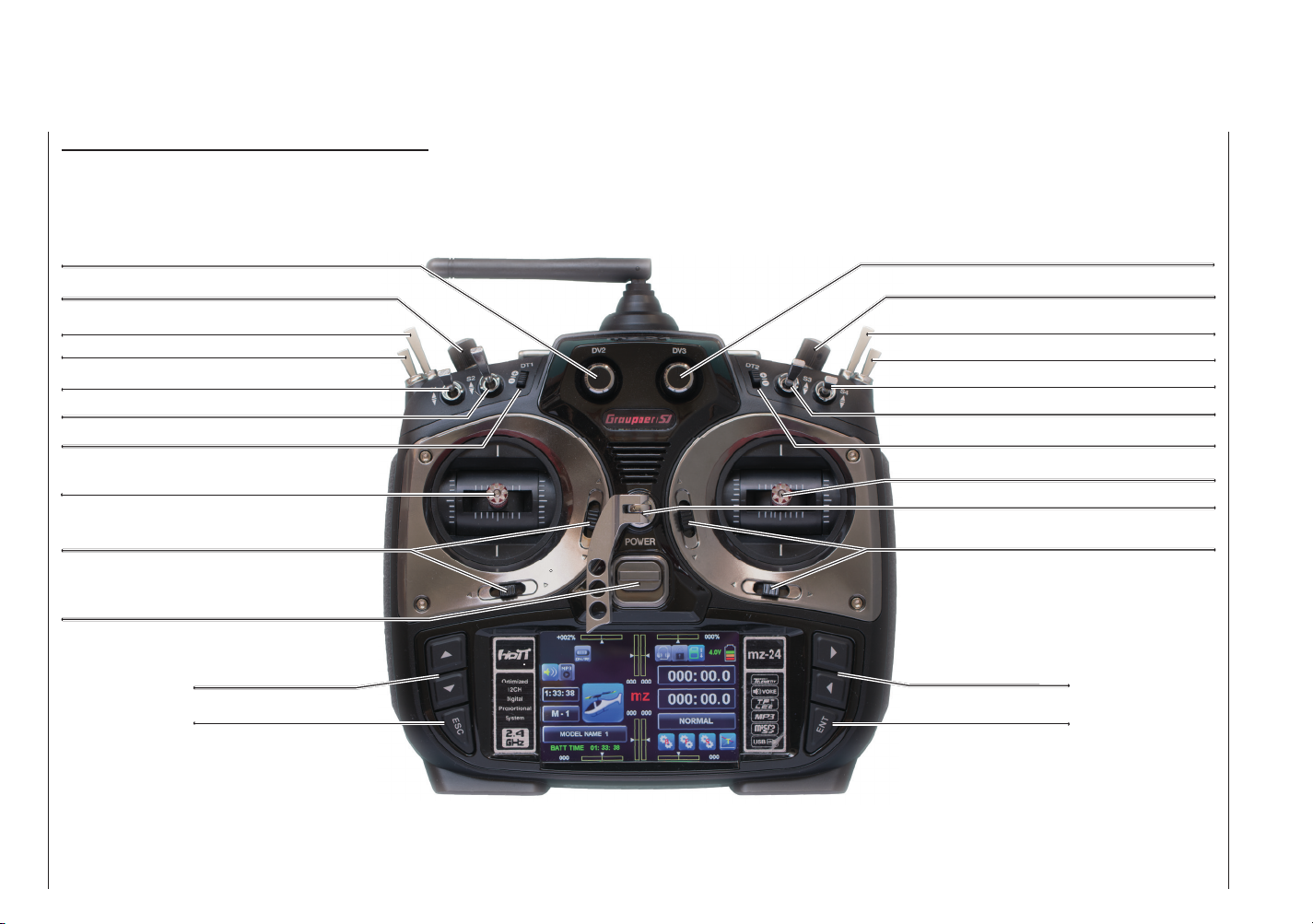
Transmitter description
Front side
Control elements on the mz-24 HoTT transmitter
proportional dial DV2
proportional dial DV1
Switch SW 6
Switch SW 5
Switch SW 1
Switch SW 2
INC/DEC buttons DT1
Left control stick
Tr i m
ON/OFF switch
Alternative selection
buttons
ESC button
Rotatable and foldable antenna
proportional dial DV3
proportional dial DV4
Switch SW 8
Switch SW 7
Switch SW 4
Switch SW 3
INC/DEC buttons DT2
Right control stick
Eyelet for carrying strap
Tr i m
Alternative adjusting
buttons
ENTER button
Description of the transmitter - Front (control elements)
18
Page 17

Button lock Digital trim
Access to adjustments can be blocked in the basic
transmitter display by simultaneously pressing the ESC
and ENT buttons for about one second. This is indicated
by a change of colour of the button icon at the top right
in the display from gray to blue/yellow:
The lock is activated immediately, but the controls
remain operational.
Press the ESC and ENT buttons again for about three
seconds to release the lock. The colour of the icon
returns to grey:
Buttons as well as ESC and
ENT
Although the two mz-18 HoTT and mz-24 HoTT
transmitters are primarily operated by touching the
touch-sensitive screen with a fi nger or the provided
stylus, the transmitters can be operated in special cases
using the two sets of three buttons on the side of the
display.
Buttons to the left of the display
• Adjusting buttons
1. Set the parameters in the setting fi elds after they
are activated by pressing the ENT button.
2. Simultaneously press the buttons to reset a
changed parameter in the active entry fi eld to the
default ( CLEAR).
3. Simultaneously pressing the buttons in the basic
display as well as in all menus with SERVO or
a Sv button switches directly to the »Servo dis-
play«.
• ESC button
Firmware version before V 1.023
Press the ESC button to confi rm the current
setting and deactivate the active settings fi eld.
Firmware version V 1.023 and higher
Pressing the ESC button brings about a stepwise return to function selection or back to the basic display.
Any setting changed in the meantime is retained.
Buttons to the right of the display
• Selection buttons
"Scrolling" through the menu lines in the setting menus or through the icons that can be called up in the
basic display.
• ENT button
Activate (confi rm) the settings fi elds by pressing the
ENT button.
With an optical and acoustic display
The two control sticks come with digital trim. Briefl y
touch the trim switch to move the neutral position of the
control stick by a specifi c value with each click. Hold
down the switch to move the trim in the corresponding
direction with increasing speed.
The adjustment is made audible by tones of varying
levels. It is therefore easy to fi nd the middle position
during fl ight without looking at the display. If you go past
the middle position, a brief pause is inserted.
The current trim values are automatically saved when
the model memory is changed. In addition, the digital
trim functions within a memory in specifi c relation to the
Quick Link (with the exception of the trim of the Throttle/
brake valves or the gas/pitch control stick called control
function "THR" (channel 1)).
When a gas motor is selected in the "Drive type" display,
page 47, the trim of the throttle control stick only functions for wing or helicopter models in the bottom half of
the control stick path, that is, only in the starting range.
The current trim positions are displayed numerically and
graphically in the transmitter's basic display (see the
picture on the left and on the next page) as well as in a
special display, see page 88.
Description of the transmitter - Buttons, button lock and digital trimming
19
Page 18
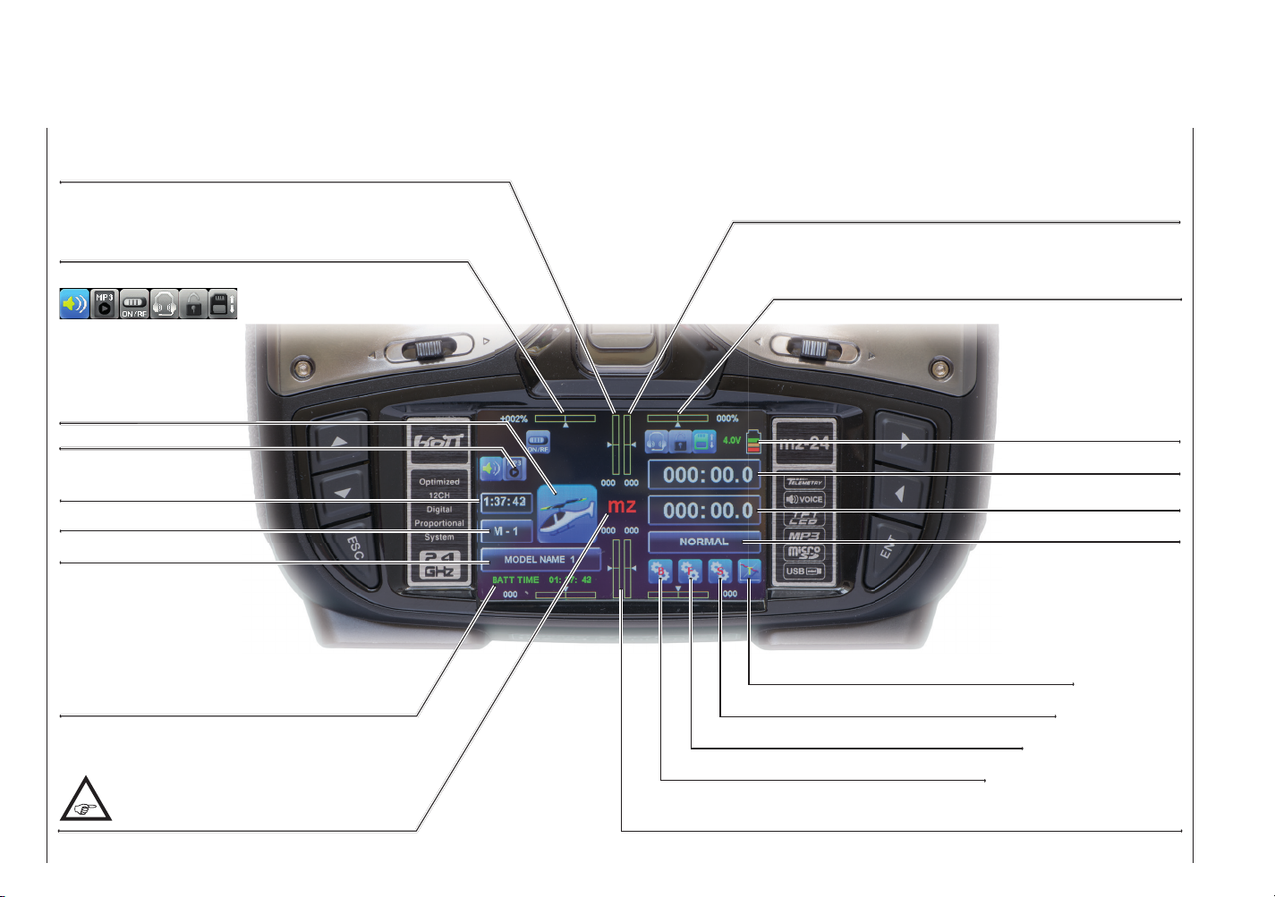
Display
Graphic display of the position of the standard, left INC/DEC
button DT 1 with a numeric position and direction display that
only comes with the mz-24 HoTT transmitter.
Graphic display of the position of the proportional dials DV 1
(mz-18 HoTT) and DV 2 (mz-24 HoTT) with a numeric
position and direction display.
Graphic display of the position of the standard, right INC/DEC
button DT 2 with a numeric position and direction display that
only comes with the mz-24 HoTT transmitter.
Graphic display of the position of the proportional dials DV 2
(mz-18 HoTT) and DV 3 (mz-24 HoTT) with a numeric
position and direction display.
These icons are for
information only:
coloured = active
Gray = inactive
Model type*
MP3 player* (as of V 1.023)
Model operating time*
Model memory …*
Model name*
Transmitter operating time: This is automatically reset
to zero after charging or changing the battery.
Touching "mz" like all of the fi elds on this page
identifi ed with an asterisk (*) at the end of the
description opens a context menu.
Three colour display of the
transmitter battery voltage.
Once a set warning threshold is reached, a warning
appears on the display and
acoustic warning signals
are emitted*.
Timer 1*
Timer 2*
Quick Link name*
Button for opening the telemetry displays
Button for opening the system settings
Button for opening the model settings
Button for opening the basic settings
Graphic display of the position of the four digital trim levers with a numeric position
and direction display.
Description of the transmitter - Display
20
Page 19
000
000
Operating the displays
The display is basically operated by touching the
desired fi eld with a fi nger or the provided stylus:
000%
0:01:23
M 1
MODEL NAME 1
BATT TIME 00: 01: 23
000 000
mz
000
000
000%
4.2V
000:00.0
000:00.0
NORMAL
By touching the model memory fi eld labelled "M 1" in
the above display with a fi nger or the provided stylus,
the "Model memory" selection menu opens.
MODEL NAME 1
BACK
01
02
03
04
05
06
MODEL NAME 1
MODEL NAME 2
MODEL NAME 3
MODEL NAME 4
MODEL NAME 5
MODEL NAME 6
NEXT
SEL
NEW
IMP.M
EXP.M
RES
CPY
In this menu, you can change the model by touching the
desired model memory.
Just as described on page 45, touch NEW to start
programming a new model, or touch the fi eld MODEL
NAME 1 at the upper edge of the display to switch
to the "Model name" entry menu, or touch BACK at
the top left to return to the previous menu item. In
contrast, touch the button NEXT [next page] (generally
using the rotation method) which is also available in
several menus to go to the next page. In the above
display of the model memory, to the display of model
memories 07 … 12, etc.
The other fi elds on the left side identifi ed with an
asterisk (*) basically function the same way.
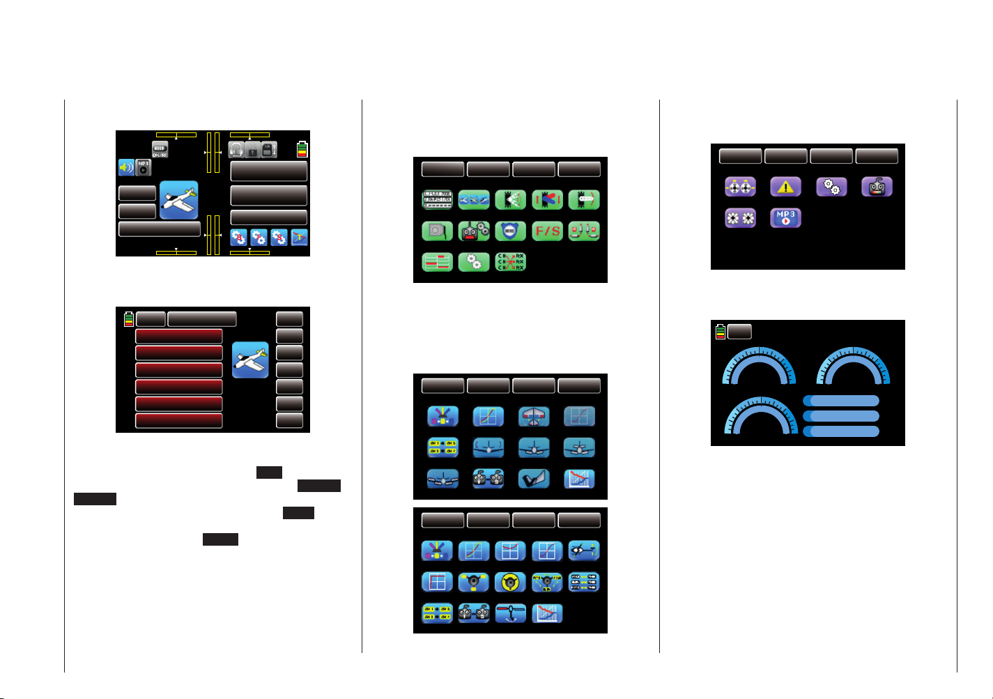
In contrast, if you touch one of the three gear icons
identifi ed with"B", "F", and "S", special selection menus
open on the bottom right from which you can switch to
other submenus. Starting with the green base menu,
see page 44the selection displays appear as follows:
BASE
E.P.A
Timer
Out.Swap
FUNCTION
Rev/Slow
Fail Safe
SYSTEM
Sub-Trim
Trim Step
BACK
Model Sel
Motor
Servo
Model Type
TX ctl
CH Set
It should be noted that they blue FUNCTION menu
which is described starting on page 100 or 171
contains model-type-specifi c submenus. The fi rst of the
two following pictures therefore shows examples of the
menu structure of a fi xed-wing model, and the second
one shows the menu structure of a helicopter model:
BASE
D/R,EXP
Aile diff
Trainer
BASE
PIT.CRV
S.Limit
PIT>>RUDD
FUNCTION
Wing MIX
Flap MIX
V-Tail
FUNCTION
THR.CRV
S.MIX
Telemetry
SYSTEM
THR.CRV
Flap sett
Telemetry
SYSTEM
Gyr/Gover
THR.MIX
BACK
Q.Link
Prog.MIX
Butterfly
BACK
Q.Link
THR.HOLD
Prog.MIX
D/R,EXP
Swash
Trainer
The pink SYSTEM menu that can be opened by
pressing "S" and is explained starting on page 208
appears as follows:
BASE
Warning
MP3
FUNCTION
Etc. Set
SYSTEM
Display
BACK
ST mode
Stick Cali
The telemetry displays which can be opened by
pressing "T" and are described in detail starting on page
213 appear as follows:
R
00dB
BACK
3.0 3.0
VO LT
0.0V
0 0
-20
6.0 6.0
40.0
TEMP
00°C
70
T
00dB
L-VOLT
0.0V
Q
S
L
000%
000%
0000ms
Description of the transmitter - Display
21
Page 20
Warnings
000
000
000
000
000%
000%
000
000
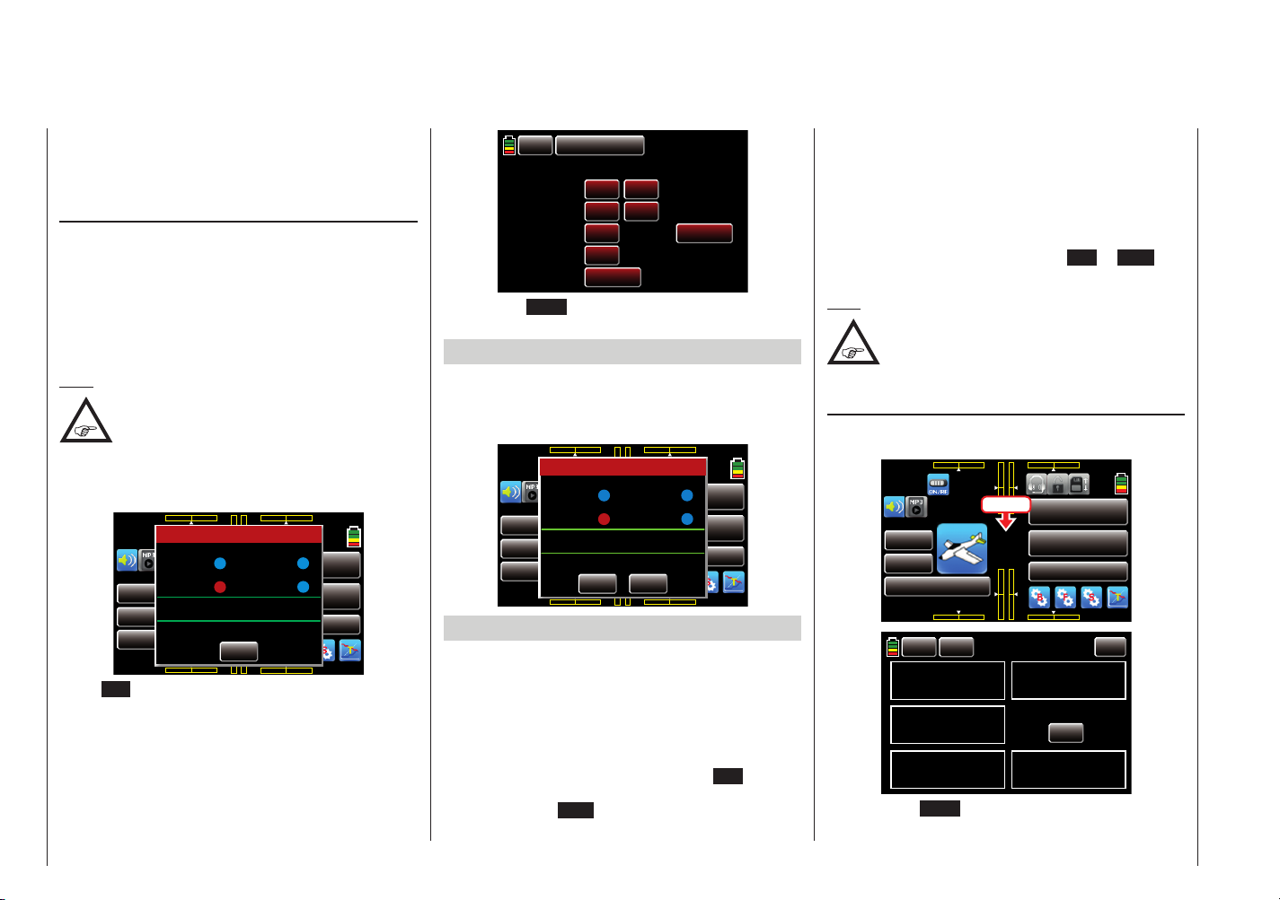
Depending on the context, different warning windows
appear in the display for the mz-18 HoTT transmitter
and the mz-24 HoTT transmitter. These can be divided
into two groups:
Warning display
These smaller windows primarily appear after the
transmitter is switched on and indicate certain operating states. In the following illustration, for instance, the
red dot after "CH1-POS" indicates that the CH1 control
stick, or as of fi rmware version V 1.023, the gas servo,
connected to output 1 on a surface model and to output
6 on a helicopter model, is not in the idle position and
there is the risk of a runaway engine.
Note:
The default "Rear idle" can be switched to
"Front idle" for fi xed-wing models in the "THR.
CRV" menu, page 144, by inverting the
control curve.
The bottom line also indicates that a receiver has not
been bound to the current model memory.
000%
RX TX
RX 00.0V
Thr.HOLD
Thr.POS
0:01:23
M 1
BIND is not setup
MODEL NAME 1
BATT TIME 00: 01: 23
Warning
000 000
mz
000
SET
000
Thr.CUT
QLink
F/S setup t.b.d
000%
3.8V
000:00.0
000:00.0
NORMAL
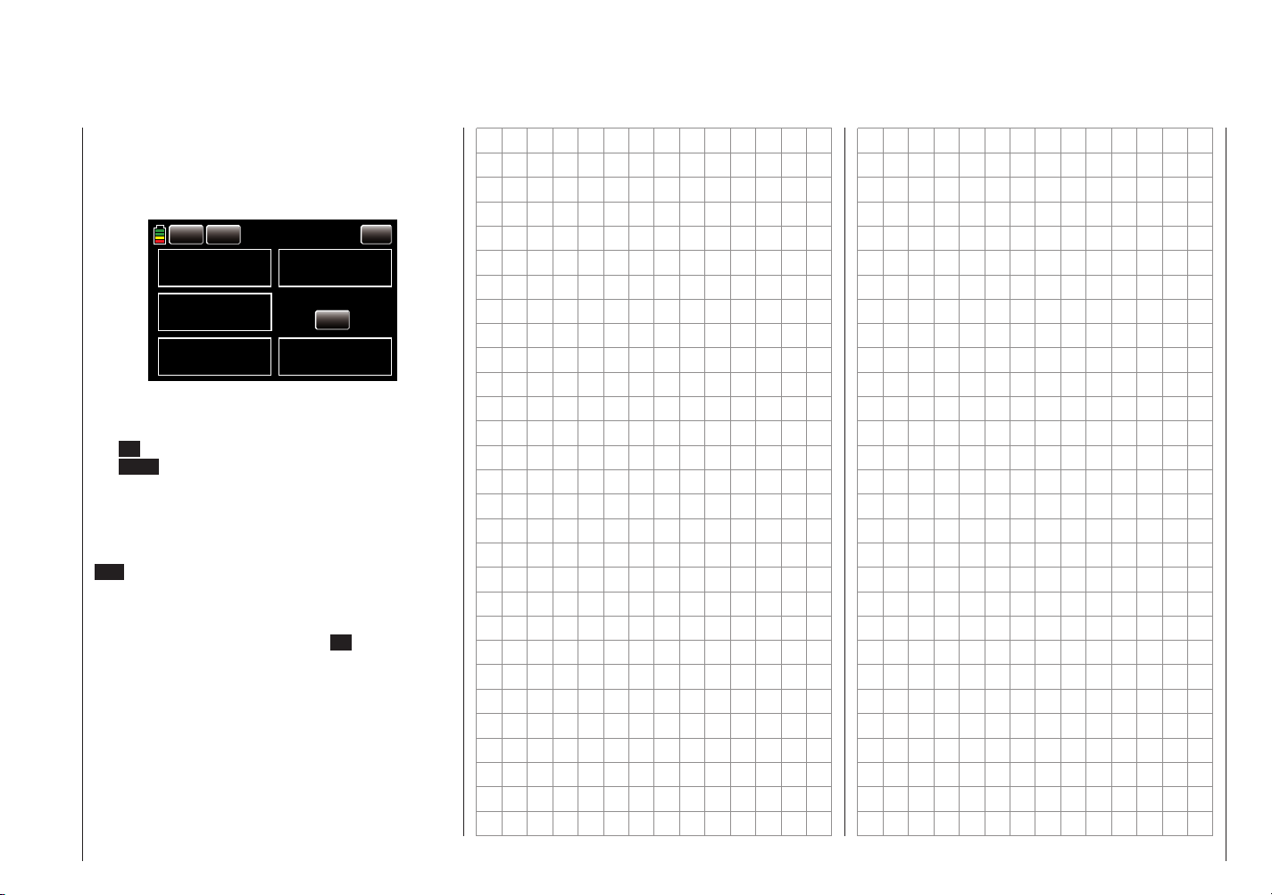
Touch SET with a fi nger or the provided stylus to go
directly to the "Transmitter control" display in which
you can link the receiver to the model memory as
described on page 74:
Description of the transmitter - Warning
22
BACK
MODEL NAME 1
RX2
RX1
OFF
BIND ON/OFF
TX OUT SET
RF ON/OFF
RANGE TEST
DSC OUTPUT
OFF
SET
OFF
OFF
PPM10
SET
RF TYPE
99sek
NORMAL
Or touch the BACK button at top left to terminate the
procedure.
Firmware versions up to and including V 1.022
If in contrast a receiver is already linked to the current
model memory and it is not switched on or out of the
range when the transmitter is switched on, a related
warning window appears:
000%
RX TX
RX 00.0V
Thr.HOLD
Thr.POS
0:01:23
Normal signal
M 1
Please select RF ON/OFF
MODELLNAME 1
AKKUZEIT 00: 01: 23
WARNUNG
Warning
000 000
mz
000
ON
Thr.CUT
QLink
000
OFF
000%
3.8V
000:00.0
000:00.0
NORMAL
Firmware versions as of V 1.023 and higher
As of fi rmware version V 1.023 and higher, switching on
the transmitter generally also activates the HF transmissions and the display shown above appears in the centre of the transmitter display. At the same time, audible
warning signals sound for a few seconds.
You now have the option of waiting a few seconds until
the display disappears automatically or maintaining the
HF transmissions by manually tapping the ON button
with your fi nger or the provided stylus, or switching them
off by tapping the OFF button.
In the fi eld between the two green lines, the message
"Normal signal" indicates that the transmitter is set to
normal remote control. Alternately, messages such as
"TEACH signal" or "PUPIL signal" can appear here.
Another – possible – variant is to display "F/S setup t.b.d"
as an indication that no fail-safe settings have yet been
made.
Answer the request "Turn RF ON/OFF" in the area below as desired by touching the button ON or OFF with
a fi nger or the provided stylus.
Note:
By default, only the monitoring of the "THR
position" is activated in the display of the
submenu "Warning" of the system menu,
page 201.
"acute warning" display
You can open this display by touching mz in the middle
of the transmitter's basic display:
RX TX
RX 00.0V
0:01:23
M 1
MODEL NAME 1
BATT TIME 00: 01: 23
BACK
CLR
TX VOLT
3.6V
STRENGTH
000%
ESC CUR.
000.0A
Touch
000 000
mz
000
000
RX VOLT
00
STRENGTH ALARM
00
ESC VOLT
00
000:00.0
000:00.0
AUTO LOAD
4.2V
NORMAL
ON
00
3.7V
ON
00
00.0V
And touch the BACK button at top left to close the
display.
Page 21
If acoustic warnings sound and the normal transmitter
display is covered by this display, take note of the
message in red. For example because the transmitter's
supply voltage has reached the warning threshold set in
the submenu "Etc.Set" of the system menu, page 202:
BACK
CLR
TX VOLT
3.5V
STRENGTH
000%
ESC CUR.
000.0A
RX VOLT
03
STRENGTH ALARM
00
ESC VOLT
00
AUTO LOAD
ON
00
3.7V
ON
00
00.0V
At the same time, the display contrast is reduced to 05
to save power.
This warning can be kept from reappearing by touching
the ON button at the top right then deleted by touching
the BACK button at the top left in the display. (In specific
cases, stop operating the model as soon as possible
and charge the transmitter).
The red number at the top right shows the number of
current warnings; in the above example, the warning is
the third one. This count can be deleted by touching the
CLR button at top left.
All other warnings in this display can be handled in
the same way. However, in the case of a field strength
alarm, you can also suppress other alarms triggered by
the low field strength by touching the ON button under
"STRENGTH ALARM" for the duration of the current
operation of the transmitter.
Description of the transmitter - Warning
23
Page 22
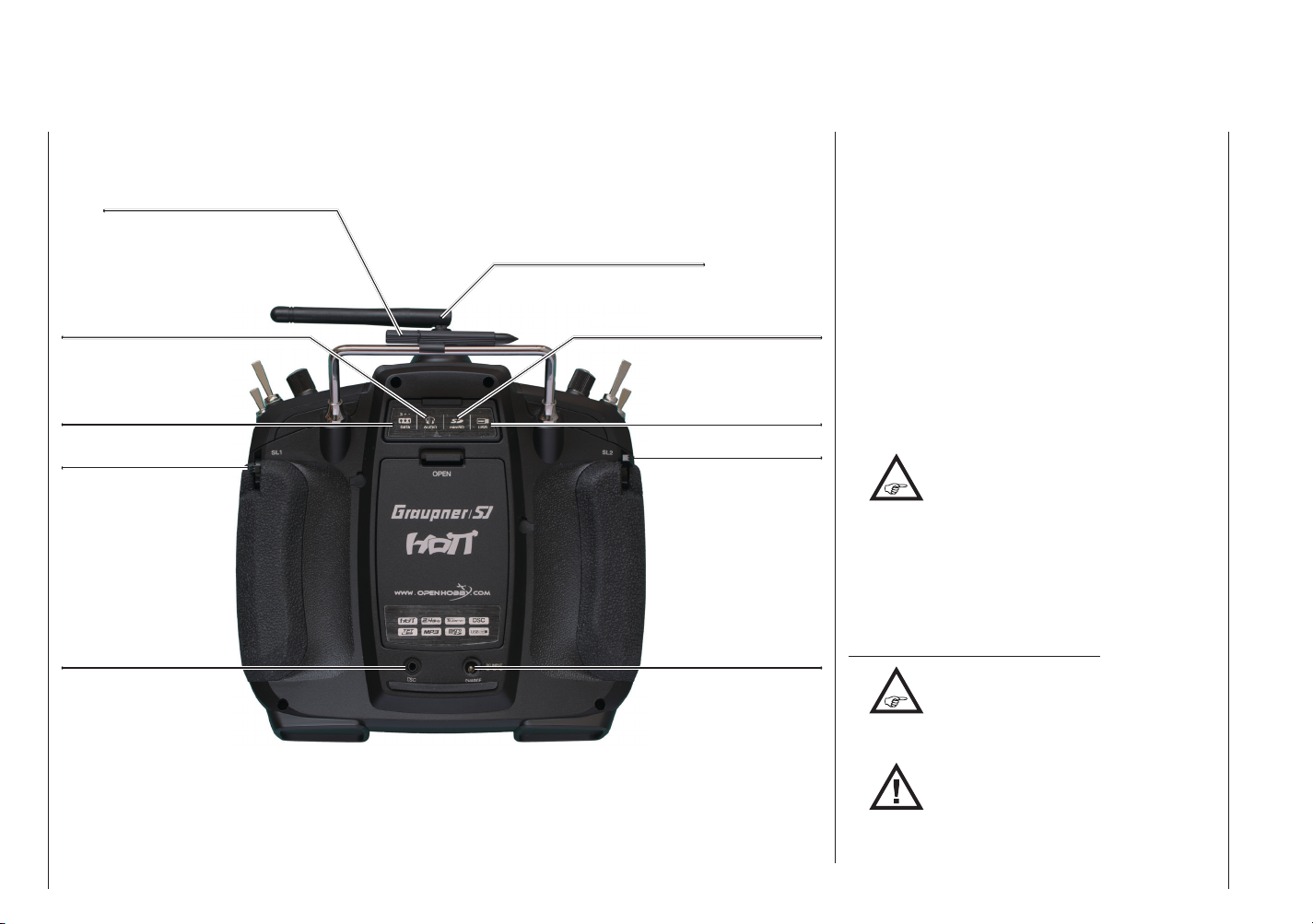
Backside of the transmitter
(The fi gure shows the mz-24 HoTT transmitter.)
Carrying handle with attached
stylus for alternatively operating
the touch-sensitive display
Rotatable and foldable antenna
Connector socket for
headphones
Data socket, for example
to connect a smart box
Proportional slider SL1
DSC socket Charging socket
Description of the transmitter - Back side and connections on the back
24
Card slot for micro SD cards
5-pin mini-USB connector
Proportional slider SL2
DSC socket
The abbreviation "DSC" is from the initial letters of the
original function, "direct servo control". With the HoTT
system, "direct servo control" using a diagnostic cable is
not possible for technical reasons.
The standard two-pin DSC socket on the back of the
mz-18 HoTT and mz-24 HoTT transmitters functions
as a trainer or pupil socket as well as an interface for
fl ight simulators or other external devices.
To ensure a correct DSC connection, observe the
following:
1. Perform any necessary adaptations in the menu.
To adapt to the transmitter to a trainer system, see
page 107.
2. Connect the other end of the connecting cable to the
desired device while observing the relevant operating
instructions.
Important:
Make sure that all the plugs are
securely inserted in the respective
plug-in connectors with a 2-pin jack plug on the
DSC side.
3. In the "Transmitter control" submenu, page 74,
you can set one of the following modes in the "DSC
output" line depending on the number of functions to
be transmitted: PPM10, PPM16, PPM18 and PPM24.
Default: PPM10.
Instructions regarding fl ight simulators:
•
to be adapted by Graupner Service.
NOTE:
•
computer interface is connected to your simulator,
the transmitter may be destroyed by electrostatic
discharge. This type of connection should therefore
sockets, and only use the provided
Given the numerous fl ight simulators on
the market, it is possible that the contacts
on the jack plug or DSC module may have
When your transmitter is directly connected
to a desktop computer or laptop by a
connecting cable (DSC cable) and/or a
Page 23
Data socket
Headphone connector
only be used if you protect yourself from electrostatic
discharge while operating the simulator by wearing a
commercially available grounding armband.
Graupner therefore strongly recommends only using
wireless simulators.
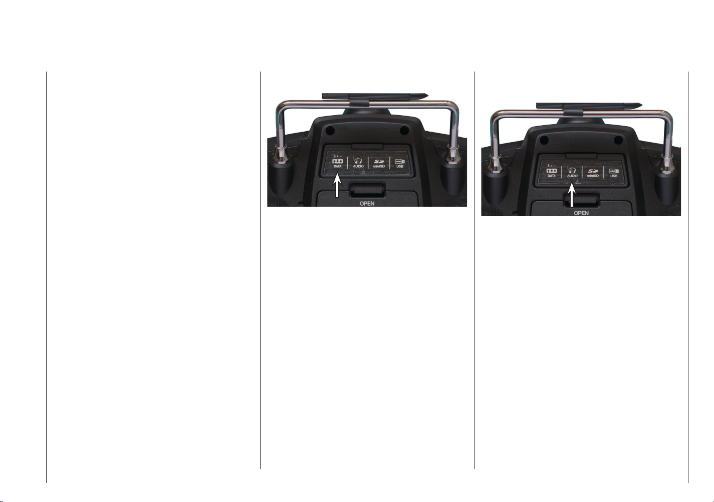
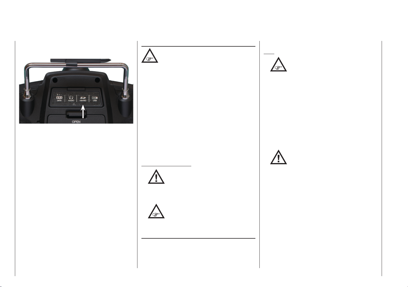
The so-called DATA socket is found under the back
cover of the mz-18 HoTT mz-24 HoTT transmitters:
This is for connecting the optional Smart Box (order
No. 33700).
Further information on the Smart Box can be found in
the main Graupner FS catalogue and on the Internet at
www.graupner.de for the respective product.
The headphone connector is found left of center under
the back cover of the mz-18 HoTT mz-24 HoTT
transmitters:
The socket is for connecting commercially available
earbuds or headphones with a 3.5 mm stereo jack (not
included in the set). When headphones are plugged in,
the transmitter's speaker is switched off, and the stylized
icon of a headphone is depicted in colour and not grey
in the basic display, see page 20.
In addition acoustic signals from the transmitter, signals
and messages associated with the "Telemetry" menu
are output via this connector. These messages are in
German language by default. Further information can
be found under "Messages" in the section "Telemetry"
starting on page 114.
Description of the transmitter - Connections on the back
25
Page 24
Card slot
micro-SD and micro-SDHC
The card slot for micro-SD and micro-SDHC memory
cards is found right of center under the back cover of the
mz-18 HoTT mz-24 HoTT transmitters:
In addition to the micro-SD memory cards that come
standard, all conventional micro-SD memory cards with
up to 2 GB and micro-SDHC cards with up to 32 GB
memory can be used. The manufacturer recommends
using memory cards with a maximum of 4 GB since this
capacity is normally suffi cient.
The memory card delivered with the transmitter like the
memory cards used in digital cameras or cell phones is
inserted into the slot behind the cover with the contacts
facing up and then locked in place. After insertion of the
memory card, the transmitter cover can be closed.
When the provided memory card or another memory
card has been inserted in the transmitter at least once,
the card is ready for use directly after the transmitter
is switched on. If the transmitter is switched on after
the memory card is inserted, the stylized memory card
icon is displayed in colour and not grey in the basic
display, see page 20. Otherwise, a few folders are fi rst
created on the memory card.
Removing the memory card
Open the cover on the back. Press the SD card slightly
toward the card slot to unlock it and then remove it.
Description of the transmitter - Connections on the back
26
Capturing and saving data
The data memory on the SD card is linked to
timer 1. Once this starts, data storage also
card is in the card slot and there is a telemetry link with
the receiver. Data storage stops when the timer 1 stops.
Timer 1 starts and stops as described in the section
"Timer" on page 80.
After data storage is fi nished, an (empty) "Models"
folder and "LogData" folder appear on the memory
card. Finally, the log fi les are saved in subfolders
called "Modelname" named according to the structure
0001_year-month-day.bin, 0002_year-month-day.
bin. If in contrast a model memory is still nameless,
the corresponding log fi les are saved in a subfolder
entitled "NoName" after the memory card is removed
from the transmitter and inserted in the card slot of a
desktop or laptop computer. The data can be evaluated
on a compatible computer using the programs found
on the downloads page for the transmitter under www.
graupner. de.
Important instructions:
•
•
Importing and exporting model memories
To exchange data between transmitters of the same
make or to backup data, model memories can be copied
to the inserted memory card, or from the memory card
to the transmitter. More information can be found in the
section "Importing/exporting from the SD card" starting
starts assuming that an appropriate memory
Claims cannot be reimbursed which
are not supported by a log fi le. For the
same reason, the transmitter must also
always be updated to the most recent software.
Please note, for technical reasons there is no
data recording during playing mp3 fi les.
In order to be aware of important
software updates, you should therefore
register at https://www.graupner.de/en/
service/product_registration.aspx. This will allow
you to automatically receive updates by e-mail.
on page 59.
Note:
•
restrictions of these fi le systems used by the memory
card and are therefore replaced by a tilde (~) during
the copying process.
• The model memories of the mz-18 and mz-20
transmitters are in principle compatible, however:
In order to import from an SD card in another a
transmitter, the desired model memory must be
copied or moved to a corresponding directory on a
desktop or laptop. For example from \\Models\mz-24
to \\Models\mz-18 or vice versa.
More information on importing from an SD card can
be found on page 59.
NOTE:
and switch functions into the respective transmitter.
Some of the special characters used in
model names cannot be transferred to FAT
and FAT32 fi le systems due to the specifi c
After importing from an SD card, you need
to check each and every model
function and in particular adapt the control
Page 25
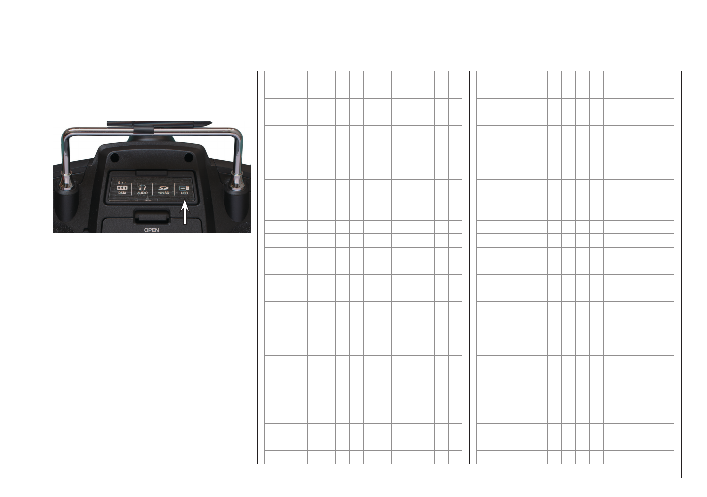
mini-USB connector
Located under the rear cover of the mz-18 HoTT and
mz-24 HoTT transmitters, there is a connector socket
for software updates as well as the date and time setting
from a desktop or laptop with one of the Windows
operating systems (XP, Vista, 7 or 8):
The USB cable that comes with the set is plugged
into this socket. The procedure for obtaining software
updates through a computer is described in the software
package instructions.
The software that the computer needs as well as the
appropriate USB driver can be found on the download
page at www.graupner.de for the respective product.
After the required driver and software are installed,
the transmitter can be updated as needed using this
connector, or the date and time can be set.
Description of the transmitter - Connections on the back
27
Page 26
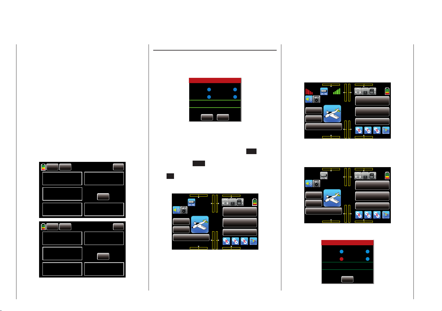
Starting up the transmitter
000
000
000
000
Introductory remarks on the mz-18 HoTT and mz-24 HoTT transmitters
Theoretically, the Graupner-HoTT system allows
more than 200 models or remote-control systems to
be operated at the same time. This number will be
signifi cantly less in practice since permits are required
for combined remote operation within the 2.4 GHz ISM
band. Generally however, more models can be operated
at the same time within the 2.4 GHz band than was
previously the case within the conventional 35/40 MHz
frequencies.
Battery charged?
Since the transmitter is delivered with an uncharged battery, you will need to charge it observing the instructions
on page 15. Otherwise, a warning signal will sound
after a short time and a related message will appear
in the basic display after a certain voltage is reached
(normally 4.8 V with the mz-18 HoTT transmitter and
3.6 V with the mz-24 HoTT transmitter) which can be
changed in the line "Bat. warning threshold" in the submenu "Etc.Set" page 202, within the system menu.
BACK
TX VOLT
STRENGTH
ESC CUR.
BACK
TX VOLT
STRENGTH
ESC CUR.
Starting the transmitter
28
CLR
4.7V
000%
000.0A
CLR
3.5V
000%
000.0A
02
00
00
04
00
00
RX VOLT
ESC VOLT
RX VOLT
ESC VOLT
AUTO LOAD
STRENGTH ALARM
AUTO LOAD
STRENGTH ALARM
ON
00
3.7V
ON
00
00.0V
ON
00
3.7V
ON
00
00.0V
Transmitter startup
As of fi rmware version V 1.023 or higher, switching on
the transmitter in the as-delivered state generally also
activates the HF transmissions and the display appears
in the centre of the transmitter display as previously:
Warning
Thr.HOLD
Thr.POS
Normal signal
Please select RF ON/OFF
ON
Thr.CUT
QLink
OFF
At the same time, audible warning signals sound for a
few seconds.
You now have the option of waiting a few seconds until
the display disappears automatically or maintaining the
HF transmissions by manually tapping the ON button
with your fi nger or the provided stylus, or switching them
off by tapping the OFF button.
You can switch off a receiver that is on and then fi rst
touch ON for demonstration purposes. You are then in
the basic display of the mz-18 HoTT or mz-24 HoTT
transmitter:
000%
RX TX
RX 00.0V
0:01:23
M 1
MODEL NAME 1
BATT TIME 00: 01: 23
000 000
mz
000
000
000%
4.2V
000:00.0
000:00.0
NORMAL
The blue switch symbol at the top left between the red
"RX" and the green "TX" means that the high-frequency
transmission of the transmitter is on.
The red "RX" and green "TX" on the left and right of
this switch symbol mean that the currently active model
memory has once been linked to a Graupner-HoTT
receiver but is presently not linked.
Once this link exists, the fi eld strength display appears
next to the red "RX" and right next to the green "TX",
and the yellow numeric display underneath shows the
current voltage of the receiver power supply, for example:
000%
RX TX
RX 05.2V
0:01:23
M 1
MODEL NAME 1
BATT TIME 00: 01: 23
000 000
mz
000
000
000%
4.2V
000:00.0
000:00.0
NORMAL
If in contrast the transmitter is switched on while the
high-frequency transmission is off, all of this information
is not displayed, and the high-frequency switch symbol
is grey:
000%
0:01:23
M 1
MODEL NAME 1
BATT TIME 00: 01: 23
000
000 000
mz
000
000
000%
4.2V
000:00.0
000:00.0
NORMAL
000
If the following warning appears in the display after the
transmitter is switched on:
Warning
Thr.HOLD
Thr.POS
BIND is not setup
Thr.CUT
QLink
F/S setup t.b.d
SET
Page 27
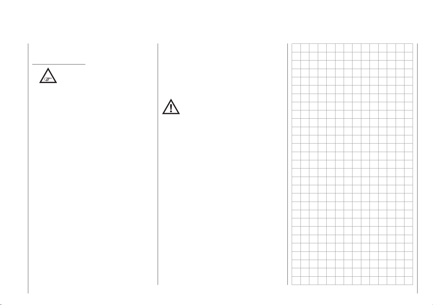
the currently active model memory is not linked to any
receiver.
Important instructions:
•
However in this context, please also note the instructions on page 76.
• Using connectors 1 … 9, a maximum of 9 servos
can be operated with the mz-18 HoTT transmitter together with the GR-24 receiver which comes
with the set and is already linked to the first model memory. Any servos which are connected to
connectors 10 - 12 remain in their middle position by default and cannot be actuated by the
transmitter.
A maximum of 12 servos can be operated with
the mz-24 HoTT transmitter together with the GR24 receiver which comes with the set and is already linked to the first model memory.
For the sake of maximum flexibility and to
prevent unintentional misuse, control channels
5-9 and 5-12 are initially not assigned to any
control elements, and the servos linked to these
channels first remain in their middle position
until an operating element has been assigned.
For the same reason, nearly all mixers are
inactive. More information on this subject can be
found on page 92.
• The basic procedure for initially programming a
new model memory starts on page 45.
• When training, linking or adjusting the remote
control, make sure that the transmitter antenna
is always far enough from the receiver antennas.
If the transmitter antenna is too close to the
receiver antennas, the receiver will overamplify
the receiver, and the red LED on the receiver will
shine. At the same time, the feedback channel
will stop working, the field strength bar in the
The transmitter which comes with the
set comes with the correct operating
settings for most countries in Europe.
transmitter display will disappear, and the
current receiver battery voltage will be displayed
as 0.0 V. The remote control is simultaneously in
fail safe mode (see page 84). That is, due to the
loss of reception, the servos remain in the last
correctly received or fail safe positions until a
new valid signal is received. In this case, move
away until the displays return to normal.
WARNING:
Never switch off the transmitter while
operating the model! If this nonetheless
accidentally happens, do not panic, and
wait until the transmitter display goes dark which
indicates that the transmitter is completely off. This
will take at least four seconds. After this time,
switch on the transmitter again. Otherwise, the
transmitter may freeze directly after being switched
on, and you will be unable to control the model. The
transmitter may only be switched on again after it
has been switched off and the described procedure
has been correctly repeated.
Starting the transmitter
29
Page 28

Updating the transmitter software Restoring the transmitter software
Program: "Restore"
Firmware updates for the mz-18 HoTT and mz-24
HoTT transmitters can be obtained via the mini-USB
connector on the back of both transmitters using a
computer operating on Windows XP, Vista, 7 or 8.
With the provided USB cable (USB-A to 5-pin mini-BUSB), connect your switched-off transmitter to your
computer by inserting one end of the USB cable directly
into the five-pin mini-USB connecting socket of the
transmitter, and the other end into a free USB connector
of your computer.
The programs and files required for updating the
transmitter as well as detailed instructions for the
corresponding product (combined into one software
package) can be downloaded from www.graupner.de.
Download this software package from the Internet, and
unpack it on your computer. All other information can
be found in the instructions that come in the software
package.
Note:
After your transmitter has been registered at
https://www.graupner.de/en/service/product_
notified of updates by e-mail.
Important instructions:
•
• Only operate your transmitter using the current
registration.aspx, you will automatically be
Please note that compatible firmware is
required for reliable communication
between the HoTT components. The
programs and files that are required to update all
HoTT components are therefore combined into a
single file that is currently named "HoTT_
Software_V4.zip".
software version. When these instructions
were drafted, the corresponding information
could be found at http://www.graupner.de/
en/supportdetail/e2a02e43-4a3b-484c-a10cb5b0cff1ed99.
If this link does not work, the same information
can be found at: www.graupner.de => Service
& Support => Update- Revisions-History of
GRAUPNER HoTT-Komponenten.
• Before each update, check the transmitter battery
charge or charge it as a precaution, and save all
model memories so that they can be restored if
necessary.
• Do not disconnect the link to the computer
during an update! Make sure that the link
between the transmitter and computer is
operational.
• After each update, check to make sure that the
models function correctly.
If a firmware update for the transmitter is unsuccessful
or the transmitter program freezes and the transmitter
cannot be switched off using the "POWER" switch,
remove the transmitter's battery after setting the switch
to "POWER = OFF" position, or pull the plug from the
transmitter battery. While making sure that the POWER
switch is in the "OFF" position, wait a few seconds and
then switch on the battery.
In this case as well, download a current software
package from the Internet and open it on your computer
or, if you have already done this, start the program
gr_Studio, and follow the information in the section
"Restoration" in the instructions provided in the software
package.
Starting the transmitter - Updating the transmitter software
30
Page 29

Personal notes
31
Page 30
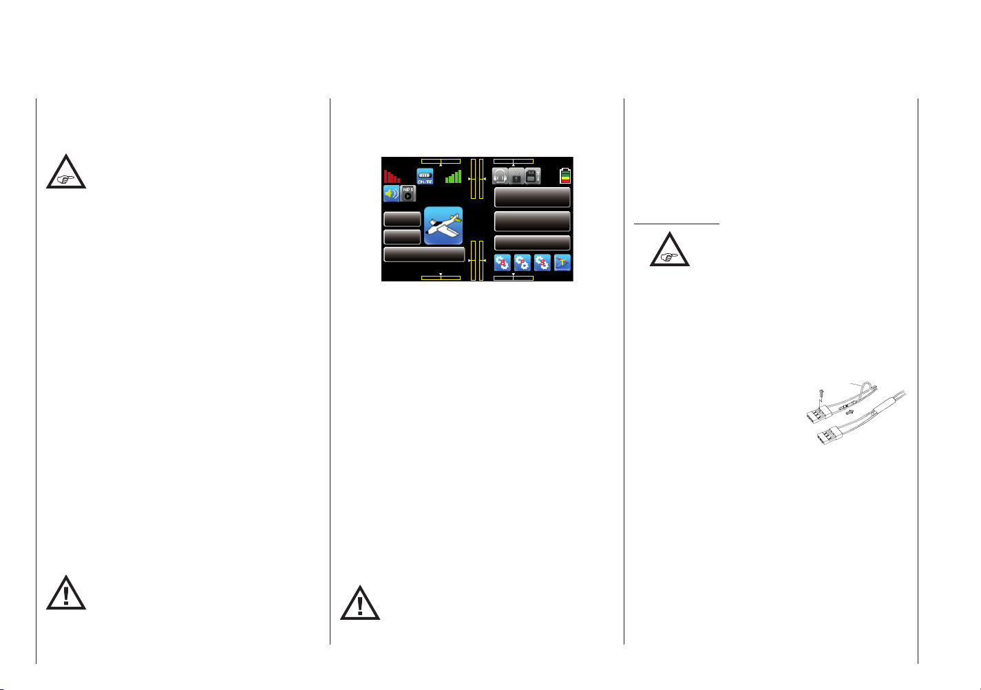
Starting up the receiver
000
000
red
Preliminary remarks
The mz-18 HoTT and mz-24 HoTT remote control sets
each come with a GR-24 bidirectional 2.4 GHz receiver
which can be connected to a maximum of 12 servos, as
well as a bidirectional GR-12L HoTT receiver.
Using connectors 1 … 9, a maximum of 9
servos can be operated with the mz-18 HoTT
transmitter together with the GR-24 HoTT
receiver which comes with the set and is already linked
to the fi rst model memory. Any servos which are
connected to connectors 10 … 12 remain in their middle
position by default and cannot be actuated by the
transmitter.
In contrast, a maximum of 12 servos can be operated
with the mz-24 HoTT transmitter together with the
GR-24 HoTT receiver which comes with the set and is
already linked to the fi rst model memory.
If you have already switched on the GR-24 HoTT receiver that comes with the set and its transmitter is not in
range or is switched off, the red receiver LED will shine
for a few seconds and then start to slowly fl ash. This
means that a link has not (yet) been established with a
Graupner-HoTT transmitter. Once a link is established,
a green LED shines continuously, and the red LED
extinguishes.
To establish a telemetry connection with the transmitter,
fi rst the Graupner HoTT receiver must be "bound" to its
model memory in its Graupner HoTT transmitter. This
procedure is called "binding." This binding only needs
to be performed once for each receiver/model memory
combination (see) and has already been done at the
factory for model memory 1 for the devices provided in
the set. Binding therefore only needs to be performed for
other receivers when the memory is changed (you can
repeat this at any time after changing a transmitter).
NOTE:
An activated receiver that has linked at least
once with "its" transmitter responds to any
incoming control signals from other model
memories of "its" transmitter like a secondary receiver.
Onboard voltage display
When a telemetry link exists, the current voltage of
the receiver power supply appears at the top left in the
transmitter display in yellow.
000%
RX TX
RX 05.2V
0:01:23
M 1
MODEL NAME 1
BATT TIME 00: 01: 23
000 000
mz
000
000
000%
4.2V
000:00.0
000:00.0
NORMAL
Temperature warning
If the receiver temperature falls below a threshold which
can be set in the receiver (-10°C by default) or exceeds
a top warning threshold (+55°C by default) which can
also be set in the receiver, the receiver emits a warning
in form of a beep that repeats approximately once per
second.
Servo connectors and polarity
The Servo connectors of the Graupner-HoTT receiver
are numbered. The polarity of the plug-in system cannot
be reversed. When inserting the plug, note the small
bevels on the side (see the fi gures on the next doublepage). Do not apply force.
The supply voltage runs through all the numbered
connectors.
With the GR-24 receiver, the two outermost vertical
connectors are for the battery. These are identifi ed with
"11+B-" and "12+B-". A corresponding servo along
with the power supply can be connected to the two
connectors using a V or Y cable (order No.: 3936.11).
NOTE:
Do not reverse the polarity of these connectors! This can destroy the receiver and
connected devices (see the next double
page).
The function of each channel is determined by the
transmitter and not the receiver. Depending on the make
and model, throttle servo connection, along with other
connections, can be different. With Graupner|JR and
Graupner remote controls, this connection is at channel
1 for fi xed-wing models, and at channel 6 for helicopters.
Note the installation instructions for the receiver, receiver antennas and servos on page 34.
Final instructions:
•
The signifi cantly higher servo resolution of
the HoTT system leads to a noticeably
more direct response in comparison to the
previous systems. Take time to familiarize yourself
with this more sensitive response!
• If you are using a speed controller with an integrated
BEC* in addition to the receiver battery, the plus
pole (red cable) may have to be removed from the
3-pin plug depending on the speed controller. In this
regard, take note of the related information in the
speed controller instructions.
Use a short screwdriver to
carefully lift the middle tab of
the plug (1), remove the red
1
2
cable (2), and use electrician's
tape to protect against shorts
(3).
Reset
To reset the receiver, hold down the SET button on the
top of the receiver while turning on the power. Hold
down the SET button of the receiver until, after about
3 seconds, the slowly fl ashing red/green LED extinguishes for about 2 seconds.
If the reset procedure is performed while the transmitter
is switched off or the receiver is not linked, the green
and red LEDs fl ash four times over about 3 seconds in
the standard GR-24 receiver that comes with the set,
then both LEDs extinguishes for about 3 seconds, and
then the red LED starts to fl ash. Release the button
once the LEDs extinguishes.
Starting the receiver
32
Page 31

Receiver firmware updates
Backing up the receiver settings
You can then start a binding procedure for the transmitter and receiver.
If a linked receiver is reset and the associated model
memory is active in the switched-on transmitter, the
LED shines green continuously for about 2-3 seconds
to indicate that your transmitter/receiver system is ready
to use.
Please note the following:
Resetting resets all of the settings in the
receiver to the factory settings with the
exception of the binding information.
If a reset is performed accidentally, all of these
settings that were made using the "Telemetry" menu
in the receiver should be restored.
Resetting is particularly recommendable when you
want to switch a receiver to a different model. This
makes it easy to keep settings which do not match
from being transferred.
Receiver firmware updates can be obtained via the
receiver telemetry connection using a computer
operating on Windows XP, Vista, 7 or 8. To do this, you
will need a USB interface (order No. 7168.6) and the
adapter cable (order No. 7168.S) that come with the
set. The programs and files which are also required for
updating the transmitter as well as detailed instructions
for the corresponding product (combined into one
software package) can be downloaded from www.
graupner.de.
Download this software package from the Internet, and
unpack it on your computer. All other information can
be found in the instructions that come in the software
package.
Note:
After your receiver has been registered at
https://www.graupner.de/en/service/product_
registration.aspx, you will automatically be
notified of updates by e-mail.
The software package downloaded from the Internet
and opened on your computer contains the program
"Firmware_Upgrade_grStudio". This program may
already be installed on your computer.
Using the "Receiver settings" section of the Firmware_
Upgrade_grStudio program, you can save all of the
settings programmed in a receiver within a file on the
computer so that you can upload them to the receiver
if needed. This makes it unnecessary to have to
reprogram the receiver using the "Telemetry" menu.
The USB interface (order No. 7168.6) and the interface
cable (order No. 7168.S) that come standard with the
mz-18 HoTT (order No. S1005) and mz-24 HoTT
(order No. S1006) remote control sets are required for
this program.
All other information can be found in the instructions that
come in the software package.
Starting the receiver
33
Page 32

Installation instructions
Servo mounting lug
Tubular brass spacer
Installing the receiver
Whatever Graupner receiver system you use, the
procedure is the same.
receiver. In addition to steel parts, this includes carbon
fiber parts, servos, fuel pumps, every kind of cable, etc.
It is preferable to install the receiver away from all other
installed parts at an easily accessible location in the
model. Servo cables may not be wound around
antennas or run next to them.
Note that the cables can shift under the influence of
acceleration during flight. You therefore need to make
sure that the cables cannot move to be directly adjacent
to antennas. Moving cables can interfere with reception.
Tests have shown that installing an individual antenna
vertically yields the best results for distant flights. In the
case of diversity antennas (two antennas), the active
end of the second antenna should be at a 90° angle
from the end of the first antenna, and the distance
between the active ends should ideally be more than
125 mm.
If the fuselage are made of carbon fiber, the ends of the
antennas should extend from the fuselage by at least
35 mm. In both cases, the approx. 145 mm standard
antennas for HoTT receivers should be exchanged with
antennas that are 300 mm or 450 mm long (order No.
33500.2 and order No. 33500.3, respectively).
The connectors identified as "X+B-" on the GR-24 HoTT
receiver that comes with the set are for the battery. The
power supply runs through all the numbered connectors,
and the power can in principle be supplied through any
of the 12 connectors. If applicable, use a V or Y cable
(order No. 3936.11).
Due to the additional power loss, perpendicular
connectors 8 … 10 of the GR-12 receiver should not be
used to connect to a receiver battery.
The function of each channel is determined by
the transmitter and not the receiver. The channel
34
Note that the receiver antennas must remain
at least 5 cm from all large metal parts or
wires that do not come directly from the
Installation instructions
assignment can be changed in the receiver by
programming using the "Telemetry" menu. It is however
recommended to do this on the transmitter using the
"Output swap" option, see page 96.
To follow are a few examples and suggestions for
installing remote-control components in the model:
1. For flying models, the receiver is installed behind
a strong bulkhead and is protected against dust
and splash water in car and ship models. When
you install your receiver, make sure that it is not
excessively airtight to prevent it from overheating
during operation.
2. All of the switches must be installed so that they
are not influenced by exhaust or vibration. The
switch knob must be freely accessible over its entire
operating range.
3. Install the servos on rubber grommets with tubular
brass spacer to protect them from vibration. Do not
overtighten the fixing screws; this could counteract
the vibration protection provided by the rubber
grommets. The system offers both safety and
vibration protection for your servos when the servo
fixing screws are properly tightened. The following
figure shows how to correctly mount a servo. The
tubular brass spacer are inserted from below into the
rubber grommets:
Retaining screw
Rubber grommet
4. The servo arms must be freely movable throughout
their operating range. Make sure that no linkage
parts block the free movement of the servo.
5. Connect the receiver's power supply cable(s) and the
servo connecting cable to the receiver as follows:
They should never be connected as follows:
NOTE:
With GR-24 receivers, servos or other
components are only connected
horizontally at connectors 8, 9 and 10.
Components and in particular the receiver battery
must never be connected flat as shown in the figure
to the other connectors to 1 to 7 and 11 and 12. This
will immediately short out the receiver battery,
destroy the other connected components, and
immediately void all warranties.
In contrast, the sequence for connecting the servos
Page 33

Receiver power supply
depends on the model type. Refer to the connector
assignments on pages 40 and 41.
In addition, consult the safety instructions on
pages 4 … 12.
To prevent uncontrolled movements of the
servos connected to the receiver system,
during startup
first switch on the transmitter
and then the receiver.
When turning off the model,
first switch off the receiver
and then the transmitter.
When programming the transmitter, make sure that an
electric motor cannot accidentally start. When a gas
motor with an automatic starter is used, make sure
that it cannot unintentionally start. For safety's sake,
disconnect the drive battery or the fuel supply.
To safely operate the model, a reliable power
supply is required. If the receiver voltage
shown on the transmitter display always drops
or is generally (too) low even though the linkage moves
freely, the battery is full, the cross-section of the battery
connecting cable is sufficient, and the transition resistance that the plug-in connectors is minimal, etc.,
observe following:
First make sure that the battery is fully charged when
initially operating the model. Make sure that the
resistance of the contacts and switches is low. Measure
the voltage drop over the installed switch cables under
a load since even robust, new switches cause a voltage
drop of up to 0.2 V. This value can be several times
higher due to aging and oxidation of the contacts. In
addition, constant vibration and shaking of the contacts
also gradually increases the transition resistance.
Furthermore, even small servos such as a Graupner/
JR DS-281 draw a stall current up to 0.75 A when you
stop under load. Four of these servos in a foam seat can
hence draw up to 3 A from the onboard power supply.
Furthermore, servos connected to a 2.4 GHz receiver
receive control pulses more frequently than comparable
receivers in the classic frequency range. This affects
the power consumption of the receiver system as well
as the characteristic of many modern digital servos of
maintaining the last position specified by the last control
pulse until the next pulse arrives.
You should therefore choose a power supply that does
not fail under a high load and always provides sufficient
voltage. To calculate the required battery capacity, add
at least 350 mAh for each analog servo, and at least
500 mAh for each digital servo.
Using this method, a battery with 1400 mAh represents
the absolute minimum for supplying power to a receiver
with four analogue servos. In your calculation, also
include the receiver which requires about 70 mA due to
its bidirectional function.
Apart from the above considerations, it is generally
recommendable to connect the receiver to the power
supply using two cables. As usual, connect cable "1"
to the "12+B-" receiver connector, and cable "2" to the
opposite end of the connector strip labelled "11+B-"
when for example using a switch or voltage regulator
with two power supply cables leading to the receiver.
Between the cable and receiver, you can use a V or
Y cable (order No. 3936.11, see figure) if one or both
receiver connectors also need to be connected to a
servo, speed controller, etc. With the double connection
to the switch or voltage controller, you not only reduce
the risk of a cable rupture but also ensure an even
power supply to the connected servos.
If you connect a separate battery to each battery connector, be sure that each of the batteries has the same
rated voltage and capacity. Never connect different
battery types or batteries with strongly different charges
since this can cause an effect similar to a short circuit.
In such cases for safety reasons, insert voltage stabilizing elements such as PRX-5A receiver power supplies
between the batteries and receiver:
Aux. function
Y-lead
Order No. 3936.11
PRX stabilised
receiver power supply
Order No. 4136
For safety reasons, never used battery boxes or dry
batteries.
The voltage of the onboard power supply is shown at
the top left of the transmitter display in yellow text:
Installation instructions - Receiver power supply
35
Page 34

000%
000
000
RX TX
RX 05.2V
0:01:23
M 1
MODEL NAME 1
BATT TIME 00: 01: 23
000 000
mz
000
000
000%
4.2V
000:00.0
000:00.0
NORMAL
If the voltage falls below the warning threshold
(normally 3.8 V) which can be adjusted in the "RX
SERVO TEST" display of the "SETTING & DATA VIEW"
of the "Telemetry" menu, starting on page 124, a
visual and acoustic low-voltage warnings are generated.
The battery level should be checked
regularly. Do not wait to charge the battery
until the voltage decreases enough for a
warning signal to be generated.
Note:
A summary of the batteries, chargers and
measuring devices for checking the power
sources can be found in the main Graupner
FS catalogue as well as on the Internet at www.
graupner.de. A selection of suitable chargers is offered
in the table on page 16.
Receiver system power supply
NiMH battery packs with 4 cells
With a traditional 4-cell pack, you can reliably operate
your Graupner HoTT system providing that the above
conditions are observed, and assuming that the packs
have a suffi cient capacity and charge.
NiMH battery packs with 5 cells
Battery packs with fi ve cells offer greater leeway in
comparison to 4-cell packs.
You should note, however, that not every servo available
on the market can handle the voltage from a 5-cell pack
over the long term, especially when the pack is freshly
charged. Some of these servos audibly "growl" when
operated with a 5-pack.
You should therefore note the specifi cations
for your servo before you choose to use a
5-cell pack.
LiFe packs with 2 cells
Given the above considerations, these cells are the best
choice.
LiFe cells are also available in a hard plastic housing
to protect against mechanical damage. Like lithium
polymer cells, LiFe cells can be charged quickly with
suitable chargers and are comparably robust.
In addition, this type of cell can undergo signifi cantly
more charging/discharging cycles than conventional
LiPo batteries. The comparatively high rated voltage
of 6.6 V of two cell LiFe battery packs do not pose any
problems to Graupner HoTT receivers or the servos,
speed controllers, gyros, etc. which are approved for
operation with this higher voltage.
However, practically all of the previously
marketed servos, speed controllers, gyros,
etc. as well as many which are offered
today have a permissible operating voltage range of
4.8 to 6 V. Stabilized voltage control such as the PRX
(order No. 4136) is therefore needed to connect
them to the receiver. Otherwise, the connected
devices may quickly become damaged.
LiPo packs with 2 cells
LiPo batteries are lighter than NiMH batteries yet offer
the same capacity. LiPo batteries also come in a hard
plastic housing to protect against mechanical damage.
The comparatively high rated voltage of 7.4 V of two
cell LiPo battery packs do not pose any problems
to Graupner HoTT receivers or the servos, speed
controllers, gyros, etc. which are approved for operation
with this higher voltage.
However, practically all of the previously
marketed servos, speed controllers, gyros,
etc. as well as many which are offered
today have a permissible operating voltage range of
4.8 to 6 V. Stabilized voltage control such as the PRX
(order No. 4136) is therefore needed to connect
them to the receiver. Otherwise, the connected
devices may quickly be damaged.
Charging the receiver battery
The charging cable (order No. 3021) can be connected
directly to the receiver battery to charge it. If the battery
in the model is connected by a power supply cable
(order No. 3046, 3934, 3934.1 or 3934.3), the battery is
charged via the charging socket integrated in the switch,
or a separate charging connector. The switch for the
power supply cable must be set to "OFF" for charging
.
Polarity of the receiver
battery plug
Installation instructions - Receiver power supply
36
Page 35

Definition of terms
Control, function input, control channel, mixer, switch, control switch
To make it easier to use the mz-18/24 HoTT manual,
we offer a few definitions of terms that appear
repeatedly in the manual.
Control function
A control function is understood as the signal for a
specific control function independent of the signal within
the transmitter. With airplanes, the control signals would
be throttle, rudde, aileron or elevator; with helicopters,
these would be pitch, roll, nick or yaw. The signal of
a control function can be transmitted directly into one
control channel, or through a mixer to several control
channels. A typical example of the latter are separate
aileron servos, or the use of two roll or elevation servos
in helicopters. The control function includes the influence
of the mechanical control path on the corresponding
servo. This can be spread or concentrated and modified
from linear to highly exponential.
Controls
Controls are the control elements on the transmitter
that are activated directly by the pilot that control
the connected servos, speed controllers, etc. on the
receiver. These include:
• The two control sticks for control functions 1 to 4 and
its trims. These four functions in both model types
(wing and helicopter) can be exchanged using the
mode setting in the software, such as throttle left
or right. The control stick function for Throttle/brake
control for fixed-wing models or throttle/pitch control
in helicopters is frequently identified as the CH1
control.
• The two (mz-18 HoTT) or four (mz-24 HoTT)
proportional dials DV1 and DV2 or DV1 … DV4
• The two side proportional rotary controls SL1 and
SL2 mounted on the bottom.
• Switches S1 … S8
• INC/DEC buttons DT1 and DT2 of the mz-24 HoTT
transmitter
With the type DV and SL proportional controls as well
as the INC/DEC buttons, the servos directly follow the
control position, whereas only a two or three-stage
adjustment is possible with a switch.
The assignment of the controls and switches to servos
5 … 9 of the mz-18 HoTT transmitter or 5 …12 of the
mz-24 HoTT transmitter is freely programmable.
Important note:
In the basic programming for the transmitter, inputs 5 … 8 and 5 … 11 for helicopters
and 5 … 9 and 5 … 12 for airplanes are
generally free, that is, not yet assigned.
Function input
This is an imaginary point in the signal flow and should
not be confused with the control connector on the
printed circuit board. The selected control mode and the
settings in the "TX OUT SET" line of the "TX ctl" submenu (Transmitter control) of the base menu influence
the sequence beyond the physical connecting points,
and this can generate differences between the number
of function inputs and the number of subsequent control
channels.
Control channel
From the point at which a signal contains all control
information necessary for a particular servo, whether
directly from the control or indirectly via a mixer, the
term control channel is used.
For example, the "aileron" control function of a
fixed-wing model for the model type "2AILE" is
divided into control channels for the left and
right aileron. Analogously, the "Roll" control function for
the helicopter model "3Sv(2Roll)" governs the
control channels for both the left and right roll servo.
This signal is only influenced by the settings made in the
submenus "E.P.A" (end point adjustment), "REVERSE"
(servo reverse/delay) and "Sub-Trim" (servo middle
and neutral position) to adjust the servo, and possibly
the settings in the submenu "OUT.SWAP" (transmitter
output) and is then transmitted by the transmitter
through the RF module. Once it arrives in the receiver,
this signal may be modified by settings saved in the
"Telemetry" menu, after which it controls the associated
servo.
Mixer
The transmitter program contains a variety of mixing
functions. These allow a control function to influence
several servos, or several control functions to influence
one servo.
In this context, you can refer to the numerous mixing
functions described starting on page 98.
Switch
The series of toggle switches S1 … S8 can also be
included in the control programming. The switches are
however generally also intended to switch program
options such as to start and stop the timers, activate
and deactivate mixers, as trainer switches etc. Each of
the switches can be assigned any number of functions.
Related examples are listed in the manual.
Control switch
Since it is occasionally practical to automatically switch
a timer or a function on or off when a control is in a
specific position (a stopwatch turns on/off to measure
engine operating time), the program for the mz-18
HoTT and mz-24 HoTT transmitters also allows you to
program control switches.
With these control switches, all you have to do is specify
the switching point along the control path in the direction
of switching. More information can be found in the
section "Control, switch and control switch assignment“
from page 38.
Definition of terms
37
Page 36

Control, switch and control switch assignment
Basic procedure
In many places in the program, you can actuate a
control function with a freely selectable control (ST1 …
4, DV1 … max. D4, DT1 and DT2, SL1 and SL2), switch
(S1 … 8), or switch between settings by a switch (S1 …
8) or control switch (see below). In both cases, multiple
assignments are possible. (The distinction between a
control and switch is explained in the section "Definition
of terms" on page 37.) It should be noted however
that incorrect responses may arise from functional
overlaps such as using the same physical switch as a
switch to switch between Q.Link and as a control for
Q.Link trim. In such cases, you should change your
switch assignment.
Since the same method is used to assign the controls
and switches in all relevant menus, the basic procedure
will be explained at this point which will allow you to
focus on the specifics in the detailed menu descriptions.
Control and switch assignment
In the "CH set" submenu (control assignment), starting
on page 92, you can …
SERVO
T:CO
7.
Aux 2
Aux 3
8.
9.
Aux 4
Aux 5
10.
Aux 6
11.
12.
Aux 7
NONE
NONE
NONE
NONE
NONE
NONE
1.
2.
3.
4.
5.
6.
BACK
Throttle
Aileron 1
Elevator
Rudder
Aileron 2
Aux 1
Graubele
ST 1
ST 2
ST 3
ST 4
NONE
NONE
… assign transmitter inputs 5 … 9 and 5 … 12 to
operate servos, as well as any control stick (ST1 …
ST4) and control identified as "DVx", "SLx" or "DTx", or
any switch identified as "S1 … S8".
The following window appears in the display after
touching the corresponding button, such as the NONE
button to the right of "AUX 1" at the bottom edge of the
display, with a finger or the provide stylus:
SERVO
1.
2.
3.
4.
5.
6.
BACK
Throttle
Aileron 1
Elevator
Rudder
Aileron 2
Aux 1
Graubele
ST 1
ST 2
ST 3
ST 4
NONE
NONE
7.
8.
Select
9.
NO
10.
CLR
11.
12.
Aux 2
Aux 3
Aux 4
Aux 5
Aux 6
Aux 7
T:CO
NONE
NONE
NONE
NONE
NONE
NONE
Actuate the desired control (control stick 1 … 4, DV1 …
max. DV4, SL1 … SL2, or DT1 … DT2) or switch (S1 …
S8), such as the right proportional rotary control SL1:
SERVO
T:CO
7.
Aux 2
Aux 3
8.
9.
Aux 4
Aux 5
10.
Aux 6
11.
12.
Aux 7
NONE
NONE
NONE
NONE
NONE
NONE
1.
2.
3.
4.
5.
6.
BACK
Throttle
Aileron 1
Elevator
Rudder
Aileron 2
Aux 1
Graubele
ST 1
ST 2
ST 3
ST 4
NONE
SL 1
Note:
The controls are only recognized after a
specific path. Therefore move the control to
the left or right, forward or backward until the
assignment appears on the display. If the length of travel
is insufficient, move the control in the opposite direction.
Switch and control switch assignment
The places in the program where a switch or control
switch can be assigned are identified with "CTL", such
as the following illustration of the Dual Rate/Expo
display:
BACK
Graubele
CH
D/R
EXP
CTL
SYM
+100%
000%
NULL
OFF
NORMAL
AILE
+100%
000%
S
INC
RES
DEC
On the right next to "CTL", touch the red NONE button
with a finger or the provided stylus. The following
appears in the display:
BACK
Graubele
CH
Select
D/R
NO
EXP
CLR
CTL
SYM
+100%
000%
NULL
OFF
NORMAL
ELEV
+100%
000%
S
INC
RES
DEC
Switch assignment
Operate the desired switch:
BACK
SW 1
Graubele
OFF
OFF
Control, switch, and control switch assignment
38
OFF
Page 37

In this display, you can determine the switch position
in which the selected switch is "ON" by touching the
corresponding button, for example:
BACK
SW 1
Graubele
ON
OFF
ON
If you choose the 2-stage switch SW 6 instead of the
3-stage switch SW 1, the display appears as follows:
BACK
Graubele
OFF
SW 6
OFF
Select the desired switching direction as above.
Deleting switches
After the switching assignment has been activated
as described at the beginning of this section, touch
the CLR button with a finger or the provided stylus:
Select
touch
NO
CLR
Cancelling the switch assignment
After the switching assignment has been activated
as described at the beginning of this section, touch
the NO button.
Control switch assignment
Actuate the desired control such as the elevator control
stick identified in the display with "ST 3":
BACK
CON.ST
POS
MODE
DIR
Graubele
ST 3
000
SINGLE
REVERSE
ENT
The yellow arrow to the right of the bar diagram
illustrates the current control position which can be
accepted by touching the ENT button as the switching
point in the value field to the right of "POS". Reverse the
switching direction by touching REVERSE in the line
"DIR(ection)".
In the "MODE" line, the switching function of the control
switch can be changed from on/off like a 2-stage switch
to the switching behaviour of a 3-stage switch.
In this case, be sure to specify a switching
position that is not "000". Otherwise, you
risk switching continuously back-and-forth
between the two switching states while the relevant
control is in the middle control position.
Note:
All of these switches can be given multiple assignments.
Make sure that you do not accidentally assign
competing functions to a switch. It is recommendable to
write down the switching functions.
Practical examples:
• Turning an onboard glow plug heater on and
off when a idling switching point for the THR control
stick is exceeded or undershot. The switch for the
glow plug heater is controlled at the transmitter by a
mixer.
• Automatically turning the stopwatch on and off to
measure the actual flight time of a helicopter by
means of a control switch on the throttle limiter.
• Automatically turning off the mixer "AILE RUDD"
when the brake flap extends to adapt the landing
position of the model to the ground contour when
landing on a slope without affecting the direction of
flight by rudders which are otherwise involved.
• Extend the landing flaps and retrim the elevator while
approaching a landing once the throttle control stick
is moved beyond the switching point.
• Switch on the stop watch and off to measure the
operating time of electric motors.
• …
Control, switch, and control switch assignment
39
Page 38

Free or right aileron 2 or aux. function
or speed controller (electric motor)
Free or right flap 2 or aux. function
Free or aux. function or right flap 2 / elevator
Receiver assignment
Fixed-wing models
Installation instructions
The servos must be connected to the
receiver in the indicated sequence. Outputs
that are not required are simply not assigned.
Please note following for the mz-18 HoTT transmitter:
By default, the 9-channel mz-18 HoTT
transmitter can only control outputs 1 to 9. Any
servos that are connected to outputs 10 to 12
remain in their neutral position with this transmitter.
Follow the instructions on the subsequent pages.
Fixed-wing models with and without a motor with up
to 4 ailerons and up to 4 flaps …
… and a normal tail unit or 2 elevator servos
Free or right flap 2 or aux. function
Free or left flap 2 or aux. function
Free or 2nd elevator or aux. function
Receiver power supply
Right flap or free or aux. function
Flap or left flap
Right aileron or aux. function
Rudder
Elevator or 1st elevator
Aileron or left aileron
Airbrake or throttle servo
or speed controller (electric motor)
Receiver power supply
Free or left aileron 2 or aux. function
… and a V-tail
Free or left flap 2 or aux. function
Free or aux. function
Free or aux. function
Receiver power supply
Right flap or free or aux. function
Flap or left flap
Right aileron or aux. function
Right rudder / elevator
Left rudder / elevator
Aileron or left aileron
Airbrake or throttle servo
Receiver power supply
Free or aux. function
Delta/flying wing models with and without a motor
with up to 4 ailerons/elevators and 4 flap/elevator
servos
Free or aux. function or left flap 2 / elevator
Free or aux. function
Free or aux. function
Receiver power supply
Free or right flap / elevator
Free or left flap / elevator
Free or aux. function
Free or rudder
Right elevon
Right elevon
Airbrake or throttle servo
or speed controller (electric motor)
Receiver power supply
Free or aux. function
Due to the different installation of the servos and rudder
linkages, the operating direction for certain servos may
be reversed. The following table offers assistance in this
regard.
Model
type
V-tail Reversed rudder
Servo with wrong
direction of
rotation
and elevator
Solution
Change the poles
of servos 3 + 4
in the submenu
"REVERSE"
The rudder is
correct and the
Switch servos 3 + 4
on the receiver
elevator is reversed
The elevator is
correct
The rudder is
reversed
Change the poles
of servos 3 + 4
in the submenu
"REVERSE", and on
the receiver
Delta,
Flying
wing
The elevator
and aileron are
reversed
Change the poles
of servos 2 + 3
in the submenu
"REVERSE"
The elevator is
correct and the
aileron is reversed
Change the poles
of servos 2 + 3
in the submenu
"REVERSE", and on
the receiver
The aileron is
correct and the
Switch servos 2 + 3
on the receiver
elevator is reversed
All of the relevant menus for a fixed-wing model are
identified by an wing icon in the "Program descriptions"
…
Receiver configuration - Airplane models
40
… so that you only have to deal with these menus when
programming fixed-wing models.
Page 39

Helicopter models
Free or speed governor or aux. function
Free or speed governor or aux. function
Advice to pilots switching from some older
Graupner systems:
In comparison to the receiver configuration of
some older transmitters, servo connector 1
(pitch servo) and servo connector 6 (throttle
servo) have been switched. The servos must be
connected to the receiver outputs as depicted on the
right. Outputs that are not required are simply not
assigned.
More details on the swashplate type may be found on
page 48 in the menu "Model selection".
Installation instructions
The servos must be connected to the
receiver in the indicated sequence. Outputs
that are not required are simply not assigned.
Follow the instructions on the subsequent pages.
Note:
In order to take advantage of the comfort and
safety features of the throttle limiter, starting
on page 94, a governor should be
connected to receiver output 6 instead of receiver
output 8 in the adjacent receiver configuration. More
information on this subject can be found on page 182.
Receiver assignment for helicopter models …
… with 1 to 3 swashplate servos
Free or aux. function
Free or aux. function
Free or aux. function
Receiver power supply
Gyro gain
Throttle servo or speed controller
Free or aux. function
Tail rotor servo (gyro system)
Pitch-axis 1 servo
Roll 1 servo
Collective pitch or roll 2 or
Pitch-axis 2 servo
Receiver power supply
Free or aux. function
… with 4 swashplate servos
Free or aux. function
Free or aux. function
Free or aux. function
Receiver power supply
Gyro gain
Throttle servo or speed controller
Pitch-axis 2 servo
Tail rotor servo (gyro system)
Pitch-axis 1 servo
Roll 1 servo
Roll 2 servo
Receiver power supply
Free or aux. function
All of the relevant menus for helicopter models are
identified with a helicopter icon in the "Program
description section …
… so that you only have to deal with these menus when
programming helicopter models.
Receiver configuration - Helicopter models
41
Page 40

Program description
000
000
Whoever has worked his way through this manual up
to this point will have probably tried out some form of
programming. Nonetheless, an attempt will be made to
describe each menu in detail.
As already mentioned in section "Operating the displays" on page 21, you can touch one of the three
gear icons at the bottom right of the basic display identifi ed with "B", "F" and "S" …
000%
0:01:23
M 1
MODEL NAME 1
BATT TIME 00: 01: 23
000 000
mz
000
000
000%
4.2V
000:00.0
000:00.0
NORMAL
… to open the respective selection menu. These three
menus contain all of the setting and display menus
required to program a model as well as the transmitter,
including telemetry functions.
Note:
The description of the individual menu items
starting on the next double page is offered in
the sequence provided by the transmitter.
Specifi cally, these are:
Program description
42
"B" (green base menu)
Touch the gear icon labelled "B" with a fi nger or the
provided stylus.
BASE
E.P.A
Timer
Out.Swap
FUNCTION
Rev/Slow
Fail Safe
SYSTEM
Sub-Trim
Trim Step
BACK
Model Sel
Motor
Servo
Model Type
TX ctl
CH Set
This menu contains all of the setting and display menus
that are needed to set up the model:
Name Menu Page
Model Sel
Model Type
E.P.A
Rev/Slow
Sub-Trim
Motor /
THR.CUT
TX ctl
Timer
Fail Safe
Trim Step
Servo
CH Set
Out.Swap
* hidden for models without a motor
"Model Select" 44
"Model type" 64
"End Point Adjustment" 66
"Servo reversal/control
delay"
68
"Servo neutral position" 70
"Throttle Cut"*
72
"Transmitter control" 74
"Timer" 80
"Fail-safe" 84
"Trim step" 86
"Servo monitor / test" 90
"Control setting" 92
"Transmitter output swap" 96
"F" (blue function menu)
Touch the gear icon labelled "F" with a fi nger or the
provided stylus.
Depending on the model type of the currently
active model memory, two different menu
structures are displayed. These can also vary
depending on the basic settings of the model.
The following two menus therefore only offer a selection
as an example:
Common function menus
Name Menu Page
Prog.MIX
Trainer
Telemetry
"programmable mixer" 100
"Trainer" 107
"Telemetry setting" 114
Fixed-wing models
BASE
D/R,EXP
Aile diff
Trainer
FUNCTION
Wing MIX
Flap MIX
V-Tail
SYSTEM
THR.CRV
Flap sett
Telemetry
BACK
Q.Link
Prog.MIX
Butterfly
Name Menu Page
Q.Link
D/R,EXP
Wing MIX
THR.CRV
"Q.Link setting" 132
"Dual rate, Expo" 136
"Wing mixer" 140
"THR.CRV"* 144
Page 41

Idle LOW
Prog.MIX
Snap roll
AILE diff
Flap MIX
Flap Sett
Airbrake
Butterfl y
Trainer
V-tail
Telemetry
"Idle setting"* 148
"programmable mixer" 100
"Snap role setting"* 149
"AILE differentiation"* 150
"AILE and FLAP mix"* 152
"Flap setting"* 156
"Airbrake settings"* 160
"Butterfl y setting"* 162
"Teacher/pupil system" 107
"V-tail"* 166
"Telemetry setting" 114
* May not be shown depending on the model
Helicopter models
BASE
BACK
Q.Link
D/R,EXP
FUNCTION
PIT.CRV
THR.CRV
SYSTEM
Gyr/Gover
THR.HOLD
Swash
S.Limit
S.MIX
THR.MIX
Prog.MIX
Trainer
PIT>>RUDD
Telemetry
"Throttle autorot" 190
"Swashplate mixer" 192
" Swashplate limiter" 193
"Heli mixer" 194
"Throttle mixer" 196
"programmable mixers" 100
"Teacher/pupil system" 107
"Pitch >> rudder mixer" 198
"Telemetry" 114
Common system menus
"S" (purple system menu)
Touch the gear icon labelled "S" with a fi nger or with the
provided stylus:
This menu offers transmitter-specifi c setting and display
menus:
BASE
BACK
FUNCTION
SYSTEM
Etc.Set
Display
Stick Cali
MP3
"Various settings" 202
"Display settings" 205
"Stick calibration" 208
"MP3" (only mz-24 HoTT) 210
"T" ("Telemetry displays")
Touch the gear icon labelled with "T" at the bottom right
with a fi nger or with the provided stylus:
The display switches from the basic display to a display
of the telemetry data such as:
R
00dB
BACK
3.0 3.0
VO LT
0.0V
0 0
-20
6.0 6.0
40.0
TEMP
00°C
70
T
00dB
L-VOLT
0.0V
Q
S
L
000%
000%
0000ms
THR.HOLD
Prog.MIX
Swash
Trainer
PIT>>RUDD
S.Limit
S.MIX
Telemetry
THR.MIX
NAME Menu Page
Q.Link
D/R,EXP
PIT.CRV
THR.CRV
Gyr/Gover
"Quick Links" 168
"Dual rate, Expo" 171
"Pitch curve" 175
"THR curve" 181
"Gyro/governor" 186
ST mode
Stick Cali
Warning
MP3
Etc. Set
Display
NAME Menu Page
ST mode
Warning
"Stick mode" 200
"Warning settings" 201
Program description
43
Page 42

Model selection
000%
000%
000
000
Edit model memories 1 … 30
Switch on the transmitter, and then in the basic display
of the transmitter, touch the value fi eld M x on the
left in the display with a fi nger or the provided stylus to
directly display the submenu "Model Sel", or alternately
touch the gear icon labelled "B" to open the same menu
from the base menu:
RX TX
RX 00.0V
0:01:23
M 1
000 000
mz
000
000
000:00.0
000:00.0
Touch
MODEL NAME 1
BATT TIME 00: 01: 23
BASE
Model Sel
Touch
01
02
03
04
05
06
BACK
Motor
Servo
BACK
Model Type
TX ctl
CH Set
MODEL NAME 1
MODEL NAME 1
MODEL NAME 2
MODEL NAME 3
MODEL NAME 4
MODEL NAME 5
MODEL NAME 6
E.P.A
Timer
Out.Swap
FUNCTION
Rev/Slow
Fail Safe
The following description of this extensive menu follows
the sequence of the function buttons at right edge of the
display starting with the top function Button:
4.2V
NORMAL
SYSTEM
Sub-Trim
Trim Step
NEXT
SEL
NEW
IMP.M
EXP.M
RES
CPY
NEXT (next page)
Touch the NEXT button in the display at the top right
with a fi nger or the provided stylus to switch from the
fi rst six model memories…
MODEL NAME 1
BACK
01
02
03
04
05
06
MODEL NAME 1
MODEL NAME 2
MODEL NAME 3
MODEL NAME 4
MODEL NAME 5
MODEL NAME 6
NEXT
SEL
Touch
NEW
IMP.M
EXP.M
RES
CPY
… to a display of the next six…
MODEL NAME 1
BACK
07
MODEL NAME 7
MODEL NAME 8
08
MODEL NAME 9
09
10
MODEL NAME 10
MODEL NAME 11
11
MODEL NAME 12
12
NEXT
SEL
NEW
IMP.M
EXP.M
RES
CPY
… Etc. After model memories 25 … 30 are displayed,
model memories 01 … 06 reappear for selection, etc.
SEL (change model)
Touch the selection fi eld for the desired model memory
with a fi nger or the provided stylus, for example:
MODEL NAME 1
BACK
01
02
03
04
05
06
MODEL NAME 1
MODEL NAME 2
MODEL NAME 3
Touch
MODEL NAME 4
MODEL NAME 5
MODEL NAME 6
NEXT
SEL
NEW
IMP.M
EXP.M
RES
CPY
The color of the fi eld switches from red to blue:
MODEL NAME 1
BACK
01
02
03
04
05
06
MODEL NAME 1
MODEL NAME 2
MODEL NAME 3
MODEL NAME 4
MODEL NAME 5
MODEL NAME 6
NEXT
SEL
NEW
IMP.M
EXP.M
RES
CPY
Touch the SEL icon with a fi nger or the provided stylus
on the right edge of the display:
MODEL NAME 1
BACK
01
02
03
04
05
06
MODEL NAME 1
MODEL NAME 2
MODEL NAME 3
MODEL NAME 4
MODEL NAME 5
MODEL NAME 6
NEXT
SEL
NEW
Touch
IMP.M
EXP.M
RES
CPY
… and then touch NO to terminate the process or YES
to change the model …
Basic menu - Model selection
44
Page 43

MODEL NAME 1
BACK
01
02
03
04
05
06
MODEL NAME 1
MODEL NAME 2
MODEL NAME 3
MODEL NAME 4
MODEL NAME 5
MODEL NAME 6
MODEL
CHANGE
YES
Touch
NO
NEXT
SEL
NEW
IMP.M
EXP.M
RES
CPY
… "Please wait" appears for about 1 second:
MODEL NAME 1
BACK
01
02
03
04
05
06
MODEL NAME 1
MODEL NAME 2
MODEL NAME 3
MODEL NAME 4
MODEL NAME 5
MODEL NAME 6
MODELL
Please
WECHSEL
J
Wait!!
NEXT
SEL
NEW
IMP.M
EXP.M
RES
CPY
N
After this message disappears, the model has changed,
and the name of the selected model memory appears in
the top line for confirmation:
MODEL NAME 2
BACK
01
02
03
04
05
06
MODEL NAME 1
MODEL NAME 2
MODEL NAME 3
MODEL NAME 4
MODEL NAME 5
MODEL NAME 6
Fail Safe
setup
t.b.d.
NEXT
SEL
NEW
IMP.M
EXP.M
RES
CPY
As of firmware version V 1.023 – as illustrated
above – the message "Fail Safe setup t.b.d." appears for
a few seconds, if you have not yet made any fail-safe
settings in the selected model memory.
NEW (create new model)
Note:
•
Switch between model memories
with SEL .
• In order to reach model memories with numbers
higher than 06, touch NEXT (next page) at the top
right of the display.
As described above, to set up a new model, select
a free model memory or a model memory that has
already been assigned but is no longer required. Instead
of NEXT , touch NEW with a finger or the provided
stylus at the right edge of the display:
MODEL NAME 1
BACK
01
02
03
04
05
06
MODEL NAME 1
MODEL NAME 2
MODEL NAME 3
MODEL NAME 4
MODEL NAME 5
MODEL NAME 6
NEXT
SEL
NEW
IMP.M
Touch
EXP.M
RES
CPY
After you touch NEW , the selection window in the
following display appears. In this window, you can
choose between manual and assistant-controlled
programming, or press NO to terminate the process.
In the following menus, the options for configuring a
fixed-wing model or helicopter are offered depending on
the selected model type. Since the manual programming
of a fixed-wing model is described in this section, touch
the MAN button with a finger or the provided stylus:
MODEL NAME 1
BACK
01
02
03
04
05
06
MODEL NAME 1
MODEL NAME 2
MODEL NAME 3
MAN.
MODEL NAME 4
Touch
MODEL NAME 5
MODEL NAME 6
Select
WIZ.
NO
NEXT
SEL
NEW
IMP.M
EXP.M
RES
CPY
Note:
Assistant-controlled model programming will
be subsequently addressed with reference
to programming a helicopter.
Manually programming the basic settings of a new
model
Manually programming of a model is always started by
entering the model name.
• "Model name"
MAN.
Current Model Name
MODEL NAME 2
New Model Name
A B C D E F
G H I J K L
O P
M
N
U
T
Z
NUM
V W
CL SP
SPECIAL
S
Y
CAPS
R
Q
X
EN
DE
On the screen keypad, touch the first character of
the model name to be entered with a finger or the
provided stylus.
Switch between capital and small letters and vice
versa with the CAPS button at the bottom edge of
the screen, and similarly, press the NUM button to
go to the numbers 0 … 9 and special characters.
To enter a space, touch the SP [Space] button.
You can select other special characters by touching
the SPECIAL button.
Basic menu - Model selection
45
Page 44

All other characters can be entered in the same
manner. A maximum of 15 characters can be entered
for a model name.
By touching DE [DELETE] in the bottom row of red
buttons, the last character is deleted. To delete all of
the entered characters at once, touch CL [CLEAR].
The characters which are entered in this manner
appear in the blue field above the keypad in the
sequence in which they are entered, for example:
N
T
Z
NUM
O P
U
CL SP
Graubele
Q
V W
EN
DE
SPECIAL
R
X
MAN.
Current Model Name
MODEL NAME 2
New Model Name
A B C D E F
G H I J K L
M
S
Y
CAPS
To transfer the model name into the model memory,
touch the red button EN [ENTER] at the bottom
right:
N
T
Z
CL SP
NUM
O P
U
Graubele
Q
V W
DE
SPECIAL
Touch
R
X
EN
MAN.
Current Model Name
MODEL NAME 2
New Model Name
A B C D E F
G H I J K L
M
S
Y
CAPS
MAN.
Current Model Name
MODEL NAME 2
New Model Name
Graubele
A B C D E F
G H I J K L
O P
M
N
U
T
Z
CL SP
NUM
V W
SPECIAL
S
Y
CAPS
R
Q
X
EN
DE
Touch the MAN. button at the top left to go to the
next option:
MAN.
Current Model Name
Touch
MODEL NAME 2
New Model Name
Graubele
A B C D E F
G H I J K L
O P
M
N
U
T
Z
CL SP
NUM
V W
SPECIAL
S
Y
CAPS
R
Q
X
EN
DE
• "Model Type"
Since at this juncture we want to program an
"airplane with electric drive", touch the selection field
"ACRO" with a finger or the provided stylus:
Touch
HELI
HELICOPTER
ACRO
AIRPLANE
GLID
GLIDER
• "Wing type"
… in which you can specify the number of aileron
and flap servos by touching the corresponding
selection field:
Wing Type
2A2F
2AILE2FLAP
1A
1AILE
NORMAL
1A1F
1AILE1FLAP
2A4F
2AILE4FLAP
2A
2AILE
4A2F
4AILE2FLAP
2A1F
2AILE1FLAP
4A4F
4AILE4FLAP
Note:
In contrast to the display of the 12-channel
mz-24 HoTT transmitter, only "1A" to a
max. "2A2F" are offered in the display of
the 9-channel mz-18 HoTT transmitter.
You can switch beforehand to the selection list for
delta/flying fixed-wing models by touching the top
button labelled Normal:
Wing Type
2A
2AILE
2A4F
2AILE4FLAP
DE LTA
2AILE1FLAP
4AILE2FLAP
2A1F
4A2F
2A2F
2AILE2FLAP
4A4F
4AILE4FLAP
After you select a wing type, the following display
appears …
Basic menu - Model selection
46
After selecting the basic model type, the following
appears in the display …
Page 45

• "Tail type"
…, in which you can specify the type of your tail:
NOR
NORMAL
V
V-TAIL
2ELE
2ELEVATOR
Finish your entry by selecting …
• "Propulsion type"
… for your model
:
ELEC
ELECTRIC POWER
GAS
GAS POWER
Note:
The default for " Motor off " or "Idle" =
"Rear thro position" can be switched to
"Front thro position" for fi xed-wing models
in the "THR.CRV" menu, page 144, by inverting the
control curve.
After the propulsion type has been selected, a
display appears with an overview of the previous
entries such as …
M/TYPE W/TYPE P/TYPE
NORMAL
ACRO
AIRPLANE
2AILE
T/TYPE
Normal
ELEC
ELE.POWER
ENT
…, which you can leave to go to the base menu by
touching the ENT button at the right bottom with a
fi nger or the provided stylus:
BASE
E.P.A
Timer
Out.Swap
FUNCTION
Rev/Slow
Fail Safe
SYSTEM
Sub-Trim
Trim Step
BACK
Model Sel
Motor
Servo
Model Type
TX ctl
CH Set
Entering the basic settings of a new model with an
wizzard
The previous section described the basic manual
programming of a fi xed-wing model. In the following, the
assistant-controlled programming of a helicopter model
will be described.
As described under "Model Sel" on page 44, to set up
a new model, select a free model memory or a model
memory that has already been assigned but is no longer
required.
After touching NEW , a selection window appears in
the following screenshot as described in the previous
section. In this window, you can choose between MAN.
, manual processing, or WIZ. , assistant-controlled
programming, or press NO to terminate the process.
In the following menus, the necessary settings for a
fi xed-wing model or helicopter are offered depending on
the selected model type.
Since the programming of a helicopter with the help of
an assistant is described in this section, touch the WIZ.
button with a fi nger or the provided stylus:
MODEL NAME 1
BACK
01
02
03
04
05
06
MODEL NAME 1
MODEL NAME 2
MODEL NAME 3
MAN.
MODEL NAME 4
MODEL NAME 5
MODEL NAME 6
Select
WIZ.
Touch
NO
NEXT
SEL
NEW
IMP.M
EXP.M
RES
CPY
Note:
An example of manual model programming is
described in the previous section in the
context of programming a model with an
electric motor.
Basic menu - Model selection
47
Page 46

As previously described with reference to manual model
programming, basic programming is started by entering
a model name when programming a model with an
wizzard.
• "Model name"
WIZ.
Current Model Name
MODEL NAME 2
New Model Name
A B C D E F
G H I J K L
O P
M
N
U
T
Z
NUM
V W
CL SP
SPECIAL
S
Y
CAPS
R
Q
X
EN
DE
On the screen keypad, touch the first character of
the model name to be entered with a finger or the
provided stylus.
Switch between capital and small letters and vice
versa with the CAPS button at the bottom edge of
the screen, and similarly, press the NUM button to
go to the numbers 0 … 9 and special characters.
To enter a space, touch the SP [Space] button.
You can select other special characters by touching
the SPECIAL button.
All other characters can be entered in the same
manner. A maximum of 15 characters may be
entered for a model name.
By touching DE [DELETE] in the bottom row of red
buttons, the last character is deleted. To delete all of
the entered characters at once, touch CL [CLEAR].
The characters which are entered in this manner
appear in the blue field above the keypad in the
sequence in which they are entered, for example:
O P
U
CL SP
Cobra
Q
V W
EN
DE
SPECIAL
R
X
WIZ.
Current Model Name
MODEL NAME 2
New Model Name
A B C D E F
G H I J K L
M
N
T
S
Z
Y
NUM
CAPS
To transfer the model name into the model memory,
touch the red button EN [ENTER] at the bottom
right:
O P
U
CL SP
O P
U
CL SP
Cobra
Q
V W
EN
DE
SPECIAL
Touch
Q
V W
EN
DE
SPECIAL
R
X
R
X
WIZ.
Current Model Name
MODEL NAME 2
New Model Name
WIZ.
Current Model Name
MODEL NAME 2
New Model Name
Cobra
A B C D E F
G H I J K L
M
N
T
S
Z
Y
NUM
CAPS
A B C D E F
G H I J K L
M
N
T
S
Z
Y
NUM
CAPS
Touch the WIZ. button at the top left to go to the
next option:
WIZ.
Current Model Name
Touch
MODEL NAME 2
New Model Name
Cobra
A B C D E F
G H I J K L
O P
M
N
U
T
Z
CL SP
NUM
V W
SPECIAL
S
Y
CAPS
R
Q
X
EN
DE
• "Model Type"
Since at this juncture we want to program a
"helicopter model", touch the HELI button with a
finger or the provided stylus:
HELI
HELICOPTER
Touch
ACRO
AIRPLANE
GLID
GLIDER
After selecting the basic model type, the following
appears in the display …
• "Swashplate type"
… in which you can specify the number of
swashplate servos by touching the corresponding
selection field:
1S
1SERVO NOR
2S
2SERVO 180
3S-R
3S 120(Roll)
Basic menu - Model selection
48
3S
3SERVO 140
3S-N
3S 120(Nick)
4S
4SERVO 90
Page 47

• "1SERVO NOR"
You are using a flybar system, or the swashplate
is tilted by a roll and elevator servo. A separate
servo is used for the pitch control.
(Since helicopter models with only one pitch
servo that have three swashplate servos for pitch,
elevation and roll also operate without a mix of
functions in the transmitter as is usually the case
with flybar systems, the menu item "SWASH MIX,
page 192, normally does not appear on the
multifunction menu.)
• "2SERVO 180"
The swashplate is shifted axially for the pitch
control by means of two roll servos; the elevation
control is decoupled by means of a mechanical
compensation rocker.
• "3S 120 (Roll)"
Symmetrical three-point control of the swashplate
by means of three articulations points offset by
a 120°, by means of which one elevation servo
(front or rear) and two roll servos (to the left and
right side) are connected. All of the three servos
of the swashplate shift axially for pitch control.
• "3SERVO 140"
Asymmetrical three-point control of the
swashplate by means of three articulations
points offset by a 120°, by means of which one
elevation servo (front or rear) and two roll servos
(to the left side and right front) are connected. All
of the three servos of the swashplate shift axially
for pitch control.
• "3S 120 (Nick)"
Symmetrical three-point axis as before, but
rotated 90°; one roll servo on the side, and two
elevation servos, front and rear.
• "4SERVO 90"
Four-point control of the swashplate by means of
two roll servos and two elevation servos.
Swashplate type: 1 servo
2
Swashplate type: 2 servos
2
1
Swashplate type: 3 servos (2 roll)
2
3
1
Swashplate type: 3 servos (140°)
2
1
3
Swashplate type: 3 servos (2 elevation)
1
3
2
Swashplate type: 4 servos (90°) 2 elevation / 2 roll
2
5
3
1
Directly after you make your selection, the following
display appears:
• "Propulsion type"
… where you specify whether your helicopter is
driven by an electric motor or gas motor.
ELEC
ELECTRIC POWER
GAS
GAS POWER
After you select the propulsion mode, the assistant
takes you to the first model-dependent settings in the
following display …
Basic menu - Model selection
49
Page 48

• "REV/SLOW" (servo reverse/delay)
REV/SLOW
WIZ.
NOR
NOR
NOR
NOR
NOR
NOR
0.0s
0.0s
0.0s
0.0s
0.0s
0.0s
1.
2.
3.
4.
5.
6.
NORMAL
NOR
NOR
NOR
NOR
NOR
NOR
0.0s
0.0s
0.0s
0.0s
0.0s
0.0s
INC
RES
DEC
7.
8.
9.
10.
11.
12.
Note:
In contrast to the displays of the
12-channel mz-24 HoTT transmitter, only
channels 1 … 9 are offered in the display
of the 9-channel mz-18 HoTT transmitter.
• Setting the rotational direction of the servos
independent of the Quick Link
In this display, you set the rotational direction
of the servos independent of the Quick Link by
touching the corresponding button to switch
from NOR to REV and vice versa with a finger
or the provided stylus, for example for CH8:
REV/SLOW
WIZ.
NOR
NOR
NOR
NOR
NOR
NOR
0.0s
0.0s
0.0s
0.0s
0.0s
0.0s
1.
2.
3.
4.
5.
6.
NORMAL
NOR
NOR
NOR
Touch
NOR
NOR
NOR
0.0s
0.0s
0.0s
0.0s
0.0s
0.0s
INC
RES
DEC
7.
8.
9.
10.
11.
12.
REV/SLOW
WIZ.
NOR
NOR
NOR
NOR
NOR
NOR
0.0s
0.0s
0.0s
0.0s
0.0s
0.0s
1.
2.
3.
4.
5.
6.
NORMAL
NOR
REV
NOR
NOR
NOR
NOR
0.0s
0.0s
0.0s
0.0s
0.0s
0.0s
INC
RES
DEC
7.
8.
9.
10.
11.
12.
• Setting a transmitter-side symmetrical delay
depending on the Quick Link
NOTE
Set a symmetrical delay for the
transmitter-side control signal with
buttons with the standard
labelling 0.0s . A delay which is set here affects
the servo that has the number of the delayed
receiver connector as well as all servos controlled
by the control element connected to control
function X.
To set a control-side delay, touch the desired
button normally labelled 0.0s with a finger or the
provided stylus, for example the control assigned
to input 8 in the menu "Channel set"starting on
page 92.
REV/SLOW
WIZ.
NOR
NOR
NOR
NOR
NOR
NOR
0.0s
0.0s
0.0s
0.0s
0.0s
0.0s
1.
2.
3.
4.
5.
6.
NORMAL
NOR
REV
NOR
NOR
NOR
NOR
0.0s
0.0s
0.0s
Touch
0.0s
0.0s
0.0s
INC
RES
DEC
7.
8.
9.
10.
11.
12.
The color of the option field switches from red
to blue:
REV/SLOW
WIZ.
NOR
NOR
NOR
NOR
NOR
NOR
0.0s
0.0s
0.0s
0.0s
0.0s
0.0s
1.
2.
3.
4.
5.
6.
NORMAL
NOR
REV
NOR
NOR
NOR
NOR
0.0s
0.0s
0.0s
0.0s
0.0s
0.0s
INC
RES
DEC
7.
8.
9.
10.
11.
12.
Touch the INC button at the right edge of the
display to gradually increase the value to a
maximum of 9.9 seconds:
REV/SLOW
WIZ.
NOR
NOR
NOR
NOR
NOR
NOR
0.0s
0.0s
0.0s
0.0s
0.0s
0.0s
1.
2.
3.
4.
5.
6.
NORMAL
NOR
REV
NOR
NOR
NOR
NOR
0.0s
1.2s
0.0s
0.0s
0.0s
0.0s
INC
RES
DEC
7.
8.
9.
10.
11.
12.
Touch the DEC button underneath to reduce
the value to a minimum of 0.0 s, and touch
the RES button to reset the changed value back
to the default.
Touch the WIZ. button …
NORMAL
NOR
REV
NOR
NOR
NOR
NOR
0.0s
1.2s
0.0s
0.0s
0.0s
0.0s
INC
RES
DEC
7.
8.
9.
10.
11.
12.
1.
Touch
2.
3.
4.
5.
6.
WIZ.
NOR
NOR
NOR
NOR
NOR
NOR
REV/SLOW
0.0s
0.0s
0.0s
0.0s
0.0s
0.0s
… to go to the next option, …
Basic menu - Model selection
50
Page 49

• "E.P.A" (servo travel/limit)
WIZ.
E.P.A
100%
100%
100%
100%
100%
100%
150%
150%
150%
150%
150%
NEXT
INC
RES
DEC
CH 1.
150%
CH 2.
150%
100%
CH 3.
150%
100%
CH 4.
150%
100%
150%
CH 5.
100%
– Limit Limit +
– Travel +
Note:
In order to reach control channels with
numbers higher than CH5, touch NEXT
[next page] at the top right of the display.
The travel and limitation are shown separately for
each side in this display. The setting range in both
cases is 0 … 150% of the normal travel.
The set values always refer to the settings in the
submenu "Sub-Trim".
To change a current value, touch the desired option
field with a finger or the provided stylus, for example:
WIZ.
E.P.A
100%
100%
100%
100%
100%
100%
150%
150%
150%
150%
150%
NEXT
INC
RES
DEC
CH 1.
150%
CH 2.
150%
100%
CH 3.
150%
100%
CH 4.
150%
100%
Touch
150%
CH 5.
100%
– Limit Limit +
– Travel +
The color of the option field switches from red to
blue:
WIZ.
E.P.A
100%
100%
100%
100%
100%
100%
150%
150%
150%
150%
150%
NEXT
INC
RES
DEC
CH 1.
150%
CH 2.
150%
100%
CH 3.
150%
100%
CH 4.
150%
100%
150%
CH 5.
100%
– Limit Limit +
– Travel +
Touch the INC button at the right edge of the
display to gradually increase the value of the active
option field. Touch the DEC button underneath to
reduce the current value of the active option field,
and touch the RES button to reset the changed
value back to the default.
Once all you have adjusted all of your servos, touch
the WIZ. button at the top left to switch to the next
adjustment phase:
WIZ.
E.P.A
100%
100%
100%
100%
100%
100%
150%
150%
150%
150%
150%
NEXT
INC
RES
DEC
CH 1.
150%
Touch
CH 2.
150%
100%
CH 3.
150%
123%
CH 4.
150%
100%
150%
CH 5.
100%
– Limit Limit +
– Travel +
• "D/R,EXP"
1. Display "D/R,EXP"
The classic dual rate/expo function of this menu
item allows you to switch or influence the control
deflections and characteristics of rolling, elevation
and tail rotor, i.e. control functions 2 … 4,
independent of the Quick Link using a switch if
desired.
In order to switch between the individual control
functions, touch the button on the right next to the
yellow "CH":
+100%
000%
NULL
OFF
NORMAL
AILE
Touch
+100%
000%
INC
RES
DEC
WIZ.
D/R EXP
CH
D/R
EXP
CTL
SYM
Note:
•
In the graphic of the display, the
curve characteristics are shown
directly.
• If you have created Quick Links in the
submenu "Q.Link" page 168, and have
assigned an appropriate name, it appears at
the top right such as "NORMAL". Activate the
corresponding switches if desired to switch
between Quick Links.
• By default, the dual rate and/or expo values
for the selected control function are set
for each control side. After switching the
option "SYM" added to the bottom line as of
firmware version 1020 from OFF to ON , a
simultaneous (symmetrical) setting of both
control sides is possible.
Analogous to the previously described displays,
touch the corresponding option field with a finger
or the provided stylus to change a current value,
and increase or decrease the value by touching
the INC and DEC buttons at the right side of
the display the appropriate number of times.
The adjustment range is ±125 % in the"D/R" line
and ±100 % in the "EXP" line.
Touch the RES button to reset a changed value
in a blue (active) value field to the default value.
In addition, a switch or a control switch can be
assigned in the line "CTL" as described in section
"Control, switch and control switch assignment"
Basic menu - Model selection
51
Page 50

on page 38.
2. Display "Control path setting" CH5 … 9 or
CH5 … 12
The above-described classic dual rate/expo
function now has a non-switchable dual rate
function or control path setting for the control
functions 5 … 9 of the mz-18 HoTT transmitter
and 5 … 12 of the mz-24 HoTT transmitter.
As shown in the above illustration, repeatedly
touch the button with a finger or the provided
stylus in the "CH" line until "CH5-9“ or "CH5-12"
appears:
NORMAL
CH9
CH10
CH11
CH12
+100%
+100%
+100%
+100%
D/R –
CH5-12
+100%
+100%
+100%
+100%
INC
RES
DEC
CH
CH5
CH6
CH7
CH8
WIZ.
+100%
+100%
+100%
+100%
+100%
+100%
+100%
+100%
D/R –
D/R + D/R +
Note:
In contrast to the display of the
12-channel mz-24 HoTT transmitter,
only channels 1 … 9 are offered in the
display of the 9-channel mz-18 HoTT transmitter.
Analogous to the previously described displays,
touch the corresponding button with a finger or
the provided stylus to change a current value,
and increase or decrease the value by touching
the INC or DEC buttons at the right side of the
display the appropriate number of times.
The adjustment range is ±125%.
Touch the RES button to reset a changed value
in a blue (active) value field to the default value.
3. Display "Offset setting" CH5 … 9 and 5 … 12
The last display in this series makes it possible to
adjust a control offset within the range of ± 125%
Basic menu - Model selection
52
for each of inputs 5 … 9 (mz-18 HoTT) and 5 …
12 (mz-24 HoTT).
As shown in the illustration at the top left,
repeatedly touch the button with a finger or the
provided stylus in the "CH" line until "CTL CH5-9“
or "CTL CH5-12" appears:
CH9
CH10
CH11
CH12
NORMAL
CH5-12 CTL
000%
000%
000%
000%
INC
RES
DEC
WIZ.
CH
000%
CH5
000%
CH6
CH7
000%
000%
CH8
OFFSET OFFSET
In contrast to the display of the
12-channel mz-24 HoTT transmitter,
only channels 1 … 9 are offered in the
display of the 9-channel mz-18 HoTT transmitter.
Analogous to the previously described displays,
touch the corresponding button with a finger
or the provided stylus to change a current
value, and raise or lower the value by touching
the INC or DEC buttons at the right side of the
display the appropriate number of times.
The adjustment range is ±125%.
Touch the RES button to reset a changed value
in a blue (active) value field to the default value.
Touch the WIZ. button at the top left of the display to
leave this menu and go to the next:
CH9
CH10
CH11
CH12
NORMAL
CH5-12 CTL
000%
000%
000%
000%
INC
RES
DEC
WIZ.
Touch
000%
CH5
000%
CH6
CH7
000%
000%
CH8
OFFSET OFFSET
CH
• "Pitch curve"
In this display you can adjust the pitch curve and,
as of firmware version 1.021, you can additionally
change in the line "PITCH MIN" the operating direction of the pitch stick to your needs:
Firmware version V 1.021 and higher
"Pitch min." line
In the helicopter program for the mz-18 HoTT and
mz-24 HoTT transmitters, the "rear" throttle position
is the "Pitch min." position by default.
With this option, which was introduced in firmware
version V1.021, the control direction of the pitch control stick can be easily switched from "Pitch min.
rear" to "Pitch min. front" or vice versa by touching
the REAR or FORWARD button in the "Pitch min."
line:
OFF
–100%
–100%
X-axis
L
NORMAL
–100%
Y-axis
TRIM
INC
DEC
ENT
WIZ.
Pitch min.
Pit.CRV
REAR
Curve
Touch
ST OFF
IN
OUT
POINT
After the button is touched, the confirmation prompt
appears:
Page 51

Warning
X-axis
OFF
+050%
NO
+050%
L
NORMAL
–100%
Y-axis
TRIM
INC
DEC
ENT
WIZ.
Pitch min.
Pit.CRV
REAR
Curve
ST OFF
Are you sure?
IN
YES
OUT
POINT
Touch NO with a finger or the provided stylus to terminate the procedure. Touch YES to confirm the
procedure which changes the direction of travel of
the pitch control stick.
OFF
–100%
–100%
X-axis
L
NORMAL
–100%
Y-axis
TRIM
INC
DEC
ENT
WIZ.
Pitch min.
Pit.CRV
FORWARD
Curve
IN
OUT
POINT
ST OFF
"Pitch curve" setting
Note:
•
In the graphic of the display, the curve
characteristics are shown directly.
• If you have created Quick Links in the submenu
"Q.Link" page 168, and have assigned an
appropriate name, it appears at the top right
such as "NORMAL". Activate the corresponding
switches if desired to switch between Quick Links.
Basic operating steps
• ST OFF button
Touch this button with a finger or the provided
stylus to switch on and off the graphic and
numeric display of the control stick position, for
example:
OFF
+050%
+050%
X-axis
?
NORMAL
Y-axis
000%
TRIM
INC
DEC
ENT
WIZ.
Pitch min.
Pit.CRV
FORWARD
Curve
IN
OUT
POINT
ST ON
Use the control element (throttle/brake control
stick) to then move a vertical green line between
the two endpoints "L" and "H" in the graphic. The
momentary control stick position is also displayed
numerically in the line "IN" (-100 % to +100 %).
The intersection of this line with the curve is
identified as "OUT" and can be varied at the
support points between -125% and +125%. The
control signal which is changed in this way then
affects all of the following mixing and coupling
functions.
• ENT button
Touch the button at the bottom right of the display
with a finger or the provided stylus to set up to
five additional points between the two endpoints
"L" and "H".
In the following example, the control stick is
exactly halfway between the middle and end of its
path, at +50% of the control path, and generates
an output signal that is also +50% due to the
linear characteristic.
Between the two endpoints "L" and "H", up to
five additional support points can be set, and the
distance between neighbouring support points
may not be less than approximately 25%.
Move the control stick. As long as there is a
question mark next to the right of "POINT", you
can press the ENT button set the next support
point. At the same time, the "?" is replaced with a
number:
OFF
+050%
+050%
X-axis
1
NORMAL
+050%
Y-axis
TRIM
INC
DEC
ENT
WIZ.
Pitch min.
Pit.CRV
FORWARD
Curve
IN
OUT
POINT
ST ON
The sequence in which the up to 5 points
between the edge points "L" and "H" are
generated does not matter since the support
points are automatically renumbered sequentially
from left to right after one support point is set or
deleted, for example:
OFF
–050%
–050%
X-axis
1
NORMAL
–050%
Y-axis
TRIM
INC
DEC
ENT
WIZ.
Pitch min.
Pit.CRV
FORWARD
Curve
IN
OUT
POINT
ST ON
Deleting a support point
In order to delete the set support points 1 to 5,
move the vertical line with the control stick next to
the relevant support point. Once the support point
number appears along with the associated value
in the line "POINT" and the point is red (see the
screenshot below), you can delete it by touching
the ENT button, for example:
Basic menu - Model selection
53
Page 52

OFF
000%
000%
X-axis
OFF
000%
000%
X-axis
2
?
NORMAL
Y-axis
NORMAL
Y-axis
000%
000%
TRIM
INC
Touch
DEC
ENT
TRIM
INC
DEC
ENT
WIZ.
Pitch min.
WIZ.
Pitch min.
Pit.CRV
FORWARD
Curve
IN
OUT
POINT
ST ON
Pit.CRV
FORWARD
Curve
IN
OUT
POINT
ST ON
Changing the support point value
• X-axis button (X-axis)
Activate this function by touching the button at
the bottom edge of the display with a finger or the
provided stylus.
You can then move an active (red) point to the
right by pressing the INC button, or to the left by
pressing the DEC button, for example:
OFF
000%
000%
X-axis
2
NORMAL
Y-axis
000%
TRIM
INC
DEC
ENT
WIZ.
Pitch min.
Pit.CRV
FORWARD
Curve
IN
OUT
POINT
ST ON
Touch the X-axis button again to deactivate the
function.
Basic menu - Model selection
54
Note:
•
If you move the red point horizontally
away from the current control
position, the point soon becomes
green and a "?" appears in the POINT line.
This question mark does not relate to the point
which has been moved but rather indicates
that another point can be set at the current
control position.
• Remember that the percentages in the "IN"
and "OUT" line always refer to the momentary
position of the control stick and not to the
position of the point.
• Y-axis button (Y-axis)
Activate this function by touching the button at
the bottom edge of the display with a finger or the
provided stylus.
You can then move an active (red) point upward
by pressing the INC button, or downward by
pressing the DEC button, for example:
OFF
–044%
+027%
X-axis
2
NORMAL
+044%
Y-axis
TRIM
INC
DEC
ENT
WIZ.
Pitch min.
Pit.CRV
FORWARD
Curve
IN
OUT
POINT
ST ON
Touch the Y-axis button again to deactivate the
function.
Note:
Remember that the percentages in the
"IN" and "OUT" line always refer to the
momentary position of the control stick
and not to the position of the point.
Rounding off the channel 1 curve
• ON/OFF button in the "Curve" line
The default angled curve profile can be
automatically rounded off by turning on the
rounding function by pressing this button with a
finger or the provided stylus, for example:
OFF
–044%
Touch
+027%
X-axis
ON
–044%
+027%
X-axis
2
2
NORMAL
+044%
Y-axis
NORMAL
+044%
Y-axis
TRIM
INC
DEC
ENT
TRIM
INC
DEC
ENT
WIZ.
Pitch min.
WIZ. Pit.CRV
Pitch min.
Pit.CRV
FORWARD
Curve
IN
OUT
POINT
ST ON
FORWARD
Curve
IN
OUT
POINT
ST ON
Important note:
The curves portrayed here are for
demonstration purposes only and do not
represent real pitch curves.
Additional functions
• TRIM button
The mz-18 HoTT and mz-24 HoTT transmitters
have a function that is integrated in the transmitter
program for trim up to six support points of the
two options "throttle curve" and "pitch curve"
during flight.
Open the following window by touching the TRIM
button at the top right edge of the display with a
Page 53

finger or the provided stylus:
WIZ.
MIXER
CTL
NONE
NONE
NONE
NONE
NONE
NONE
NONE
NONE
NONE
NONE
NONE
NONE
POINT Q.LINK
L
1
L
1
1
L
1
L
1
L
L
1
INC
RES
DEC
Basic operating steps
• "CTL" column:
In in the first column of the menu with the
heading "Control", select a control that
appears suitable for this purpose from the
controls offered by your mz-18 HoTT
or mz-24 HoTT transmitter.
To assign a control, touch the button in this
column in the desired line with a finger or the
provided stylus, for example:
WIZ.
MIXER
CTL
NONE
NONE
Touch
NONE
NONE
NONE
NONE
NONE
NONE
NONE
NONE
NONE
NONE
POINT Q.LINK
L
1
L
1
1
L
1
L
1
L
L
1
INC
RES
DEC
The following appears in the display:
WIZ.
MIXER
CTL
NONE
NONE
NONE
NONE
NONE
NONE
NONE
NONE
NONE
NONE
NONE
NONE
POINT Q.LINK
L
1
Select
L
1
NO
1
L
CLR
1
L
1
L
L
1
INC
RES
DEC
Then press the desired control such as the
right proportional rotary control SL1:
WIZ.
MIXER
CTL
SL1
NONE
NONE
NONE
NONE
NONE
NONE
NONE
NONE
NONE
NONE
NONE
POINT Q.LINK
L
1
L
1
1
L
1
L
1
L
L
1
INC
RES
DEC
• "MIXER" column
In the six value fields of the second column
with the header "MIXER", you can select
individual helicopter mixers, or one of the two
available mixers in any combination.
To select a mixer, touch the button in "MIXER"
column in the desired line with a finger or the
provided stylus, for example:
WIZ.
MIXER
CTL
SL1
NONE
NONE
NONE
NONE
NONE
NONE
NONE
Touch
NONE
NONE
NONE
NONE
POINT Q.LINK
L
1
L
1
1
L
1
L
1
L
L
1
INC
RES
DEC
The button color changes from red to blue:
WIZ.
MIXER
CTL
SL1
NONE
NONE
NONE
NONE
NONE
NONE
NONE
NONE
NONE
NONE
NONE
POINT Q.LINK
L
1
L
1
1
L
1
L
1
L
L
1
INC
RES
DEC
You can change the current value in the
blue (active) value field by touching the INC
or DEC buttons at the right edge of the
display the desired number of times, for
example:
WIZ.
MIXER
CTL
SL1
NONE
NONE
NONE
NONE
NONE
THR.CRV
NONE
NONE
NONE
NONE
NONE
POINT Q.LINK
L
1
L
1
1
L
1
L
1
L
L
1
INC
RES
DEC
Touch the RES button to reset a changed
value in a blue (active) value field to the
default value.
• "POINT" column
You have selected one or more mixers in
the lines of the "Mixer" column. In the "Point"
column, identify the support point(s) to be
trimmed.
To select a point, touch the button in the
"POINT" column in the desired line with a
finger or the provided stylus, for example:
Basic menu - Model selection
55
Page 54

WIZ.
MIXER
CTL
SL1
THR.CRV
NONE
NONE
NONE
NONE
NONE
NONE
NONE
NONE
NONE
NONE
You may change the current value in the
blue (active) value field by touching the INC
or DEC buttons at the right edge of the
display the desired number of times, for
example:
WIZ.
MIXER
CTL
SL1
THR.CRV
NONE
NONE
NONE
NONE
NONE
NONE
NONE
NONE
NONE
NONE
Touch the RES button to reset a changed
value in a blue (active) value field to the
default value.
Note:
When selecting an undefined point
(in the basic version of the relevant
curve mixer, the points "L" and "H"
input are set), and the associated governor
does not have any effect.
• "Q.LINK" column
If you want to, specify in the right "Q.LINK"
column the programmed Quick Links in which
the governor should be active. The number in
the value field ("1 (Normal)" in the example)
Basic menu - Model selection
56
POINT Q.LINK
L
1
L
1
1
L
1
L
1
L
L
1
POINT Q.LINK
3
1
L
1
1
L
1
L
1
L
L
1
INC
RES
DEC
INC
RES
DEC
refers to the Q.Link number which also
appears in the "Q.Link" menupage 168.
To select another Q.Link than default Q.Link1,
touch the button in the "Q.Link" column in
the desired line with a finger or the provided
stylus, for example:
WIZ.
MIXER
CTL
SL1
NONE
NONE
NONE
NONE
NONE
THR.CRV
NONE
NONE
NONE
NONE
NONE
POINT Q.LINK
3
1
L
1
1
L
1
L
1
L
L
1
INC
RES
DEC
You may change the current Q.Link number
in the blue (active) value field by touching
the INC or DEC buttons at the right edge
of the display the desired number of times, for
example:
WIZ.
MIXER
CTL
SL1
NONE
NONE
NONE
NONE
NONE
THR.CRV
NONE
NONE
NONE
NONE
NONE
POINT Q.LINK
3
3
L
1
1
L
1
L
1
L
L
1
INC
RES
DEC
Touch the RES button to reset a changed
value in a blue (active) value field to the
default value.
Note:
The settings that appear in this
display affect the same records as
those at a comparable location in
the "TRIM" display of the "THR.CRV"
submenu (see next column) which is why
changes always affect each other.
After you finish making your settings, touch
the WIZ. button at the top left of the display to
leave this menu and go to "Pitch curve":
WIZ.
MIXER
CTL
Touch
SL1
NONE
NONE
NONE
NONE
NONE
THR.CRV
NONE
NONE
NONE
NONE
NONE
POINT Q.LINK
3
3
L
1
1
L
1
L
1
L
L
1
INC
RES
DEC
Touch the WIZ. button again in the "Pitch curve"
display …
ON
–044%
+027%
X-axis
NORMAL
2
+044%
Y-axis
TRIM
INC
DEC
ENT
WIZ. Pit.CRV
Pitch min.
Touch
FORWARD
Curve
IN
OUT
POINT
ST ON
… To leave the assistant and open the next menu: …
Page 55

• "Thr.CRV"
The throttle curve can be specified by up to 7 points,
the so-called support points, along the entire control
stick travel depending on the Quick Link:
OFF
–100%
–100%
X-axis
L
NORMAL
000%
Y-axis
TRIM
INC
DEC
ENT
WIZ.
Thr.CRV
THR.Limit +100%
Curve
IN
OUT
POINT
ST OFF
The support points are set, changed and deleted
in the same manner as explained in the previous
section, "Pitch curve", starting on page 175. First
specify the throttle curve using three points, that
is, the two end points "L" and "H", as well as the
other set point "1" in the control center in order to
harmonize the motor performance curve with the
pitch curve.
Note:
•
The value displayed in the line "Throttle
limit" at top left only indicates the
position of the gas limiter.
• When selecting an undefined point (in the basic
version of the relevant curve mixer, the points "L"
and "H" input are set), and the associated governor does not have any effect.
• The settings that appear in this display affect
the same records as those at a comparable
location in the "TRIM" display of the "THR.CRV"
submenu which is why changes always affect
each other.
WIZ.
MIXER
CTL
SL1
NONE
NONE
NONE
NONE
NONE
THR.CRV
NONE
NONE
NONE
NONE
NONE
POINT Q.LINK
3
3
L
1
1
L
1
L
1
L
L
1
INC
RES
DEC
Further information for setting throttle curves can be
found starting on page 181.
Touch the WIZ. button in the "Throttle curve" display
to leave the assistant and open the next menu: …
• "GYRO" (gyro/governor)
Within this display, you can make initial basic
settings as needed for your gyro and/or for any
governor that is used in your model.
000%
000%
INH
050%
NORMAL
INC
RES
DEC
WIZ.
Gyro Suppression
Gyro Gain
Governor ACT
Governor RATE
GYRO
• Gryo Suppression
This option may normally not be
used for current standard gyro
systems. You therefore need to
consult your gyro setting instructions since
otherwise you may make it impossible to fly
your helicopter. Nonetheless, this menu was
retained to satisfy all requirements and
conventions.
This option can influence the effect of the gyro
sensor (gyroscope) as the tail rotor control stick
is moved, assuming that a gyro system is used
in which the gyro's effect can be set by the
transmitter using an additional channel, channel 7
in the Graupner remote-control system. The gyro
suppression reduces the gyro's effect in a linear
manner in proportion to the deflection of the tail
rotor control stick corresponding to the set value.
If the gyro has not been suppressed (at a value of
0%), the gyro's effect remains independent of the
control stick deflection.
The Gyro's effect can however be additionally
varied smoothly (depending on the Quick Link
if desired) between a minimum and maximum
using a control assigned in the "Gyro" line in the
"channel set" menu, page 92, for example with
one of the proportional dials DVx. More on this
subject (not discussed here for reasons of space)
can be found in the section "Gyro/governor“ from
page 186.
• Gyro Gain
NOTE:
Note that the offset values entered in
this option as well as in the line
"CH7" of the display "CTRL CH5-12"
of the menu "D/R,EXP", page 174, add up!
For the sake of clarity, make sure to only enter
or change an offset value in one of the two
options.
Most of the current gyro systems can be adjusted
for a smooth, proportional effect, you can also
choose between two different modes of action by
the transmitter.
If the gyro that you are using also has one of
these options, the alternative offset setting
enables both the normal gyro effect and "heading
lock mode" as well as flying with maximum
stabilization in normal, slow fights within this
selected mode, and reducing the gyro gain in fast
roundtrips and aerobatics.
Values up to ±125% are possible, for example:
Basic menu - Model selection
57
Page 56

WIZ.
Gyro Suppression
Gyro Gain
Governor ACT
Governor RATE
GYRO
000%
+023%
INH
050%
NORMAL
INC
RES
DEC
WIZ.
Gyro Suppression
Gyro Gain
Governor ACT
Governor RATE
GYRO
000%
+023%
ON
050%
NORMAL
INC
RES
DEC
landing.
Therefore, as described in detail in the section "THR.
HOLD" starting on page 190, make the appropriate
settings during the training phase in this display
so that the gas motor can be kept idling during the
autorotation phase without the clutch engaging and
any electric drive is definitely off, for example:
Thr.HOLD
WIZ.
Based on the these Q.Link-specific (offset)
settings, the gyro gain can also be smoothly
varied with a control such as DVx assigned in the
line "CH7" of the display "CTRL CH5-9" or "CTRL
5-12“ of the "D/R,EXP" menu, page 173.
• Governor ACT
In contrast to speed controllers that only regulate
performance like a carburettor, governors
maintain a constant the speed in the system
that they are monitoring by independently
regulating the provided output. In the case of a
gas helicopter, the control independently controls
the throttle servo like the motor control unit of
an electric helicopter. Governors therefore only
require a speed setting and not a classic throttle
curve. A deviation from the set speed occurs
when the required output exceeds the maximum
available output.
To change the current value, touch the desired
button in the "GOVERNOR" line with a finger or
the provided stylus. The display switches from
"OFF" to "ON" and vice versa, for example:
• Governor RATE
In the "GOVERNOR" line, let us say that you
have switched on the function "Governor at
CH8". In the "GOVERNOR OFFSET" line, enter
the appropriate offset value for the desired rotor
speed. The value to be set depends on the
governor as well as the desired target speed
and, after finish using the assistant, it can also be
varied for specific Quick Links, for example:
000%
+023%
ON
067%
NORMAL
INC
RES
DEC
WIZ.
Gyro Suppression
Gyro Gain
Governor ACT
Governor RATE
GYRO
This value can also be smoothly varied with a
control such as DVx assigned in the line "CH8" of
the display "CTRL CH5-9" or "CTRL CH5-12" of
the "D/R,EXP" menu, starting on page 171.
Touch the WIZ. button in the "Gyro/Gover" display to
leave the assistant and open the next menu: …
• "Thr.HOLD"
During competition, it is expected that gas engines
should be completely switched off. In the training
phase, this is a bit inconvenient since you would
have to restart the motor after each autorotation
ACT
INH
CTL
ON
SET
–100%
INC
RES
DEC
Note:
With the "Thr.CUT" option in the "BASE"
menu, there is an alternative emergency
off function.
Touch the WIZ. button in the "THR AR" display to
leave the assistant and open the next menu: …
• "FAIL SAFE"
WIZ.
CH
CH 1.
CH 2.
CH 3.
CH 4.
Delay
MODE
HOLD
HOLD
HOLD
HOLD
0.25s
SET
NEXT
STO1
STO2
SET
Since there is normally no connection with the
receiver at this juncture when setting up a model,
you may omit this menu item at the moment. Touch
the WIZ. button again, and a display appears with
an overview of your previous entries such as …
Basic menu - Model selection
58
Page 57

000
000
M/TYPE SWASH P/TYPE
Heli
HELICOPTER
3S
3SERVO 140
ELEC
ELE.POWER
ENT
…, which you can leave to go to the base menu by
touching the ENT button at the right bottom with a
fi nger or the provided stylus:
BASE
E.P.A
Timer
Out.Swap
FUNCTION
Rev/Slow
Fail Safe
SYSTEM
Sub-Trim
Trim Step
BACK
Model Sel
Motor
Servo
Model Type
TX ctl
CH Set
IMP.M (import from SD card)
Once a memory card is in an operational transmitter, a
blue memory card icon appears at the top right of the
basic display:
000%
RX TX
RX 00.0V
0:01:23
M 1
MODEL NAME 1
BATT TIME 00: 01: 23
000 000
mz
000
000
000%
4.2V
000:00.0
000:00.0
NORMAL
In the "Model Sel" menu described here …
MODEL NAME 1
BACK
01
02
03
04
05
06
MODEL NAME 1
MODEL NAME 2
MODEL NAME 3
MODEL NAME 4
MODEL NAME 5
MODEL NAME 6
NEXT
SEL
NEW
IMP.M
EXP.M
RES
CPY
… you can import compatible models into the
transmitter memory from the memory card inserted in
the transmitter's card slot.
From the list of empty model memories offered in
the "Model Sel" display, fi rst select one that appears
appropriate, such as model memory 2 which is still
available in this example. Touch the fi eld on the right
adjacent to the yellow 02 with a fi nger or the provided
stylus. The color of the fi eld switches from red to blue:
MODEL NAME 1
BACK
01
02
03
04
05
06
MODEL NAME 1
MODEL NAME 2
MODEL NAME 3
MODEL NAME 4
MODEL NAME 5
MODEL NAME 6
NEXT
SEL
Touch
NEW
IMP.M
EXP.M
RES
CPY
Then switch to the display of the data model saved on
the SD card by touching the IMP.M button in the middle
of the right column:
BACK
SD card data
Graubele
01
Soarmaster
02
03
Extra 330
Bell 47G
04
05
06
SOURCE
TARGET
YES
NO
SEL
NEW
IMP.M
EXP.M
RES
02
CPY
Touch the model to be imported from the SD memory
card with a fi nger or the provided stylus. The color
of the fi eld switches from red to blue, and additional
information and buttons appear at the bottom right.
Touch NO to terminate the action and return to the
start page. Touch YES …
BACK
SD card data
Graubele
01
Soarmaster
02
03
Extra 330
Bell 47G
04
05
06
SOURCE
Touch
TARGET
YES
NO
NEXT
NEW
IMP.M
EXP.M
02
RES
02
CPY
… and then after a short while the message "Please
wait!!" appears …
Basic menu - Model selection
59
Page 58

000
000
BACK
SD card data
Graubele
01
Soarmaster
02
03
Extra 330
Bell 47G
04
05
06
QUELLE
Please
Ziel
wait!!
J
NEXT
NEW
IMP.M
EXP.M
02
RES
02
N
CPY
… while the selected model is imported into the
selected mode memory.
Once the process is completed, the message "Please
wait!!" disappears, and the display returns to the list of
models and the transmitter:
MODEL NAME 1
BACK
01
02
03
04
05
06
MODEL NAME 1
Soarmaster
MODEL NAME 3
MODEL NAME 4
MODEL NAME 5
MODEL NAME 6
NEXT
SEL
NEW
IMP.M
EXP.M
RES
CPY
EXP.M (Export to SD card)
Use this option to export models saved in the transmitter
to a memory card inserted into the transmitter's card
slot.
Once a memory card is in an operational transmitter, a
blue memory card icon appears at the top right of the
basic display:
000%
RX TX
RX 00.0V
0:01:23
M 1
MODEL NAME 1
BATT TIME 00: 01: 23
000 000
mz
000
000
000%
4.2V
000:00.0
000:00.0
NORMAL
In the "Model Sel" menu described here …
BACK
01
02
03
04
05
06
Graubele
Graubele
Soarmaster
MODEL NAME 3
MODEL NAME 4
MODEL NAME 5
MODEL NAME 6
NEXT
SEL
NEW
IMP.M
EXP.M
RES
CPY
… you can export assigned model memories as desired
to the memory card inserted in the card slot of the
transmitter.
From the list of assigned model memories offered in the
"Model Sel" display, select the desired model memory
such as memory 2. Touch the fi eld with the selected
model name using a fi nger or the provided stylus. The
color of the fi eld switches from red to blue:
BACK
01
02
03
04
05
06
Graubele
Graubele
Soarmaster
MODEL NAME 3
MODEL NAME 4
MODEL NAME 5
MODEL NAME 6
NEXT
SEL
NEW
IMP.M
EXP.M
RES
CPY
And the next step, touch the EXP.M button with a fi nger
or the provided stylus on the right edge of the display:
BACK
01
02
03
04
05
06
Graubele
Graubele
Soarmaster
MODEL NAME 3
MODEL NAME 4
MODEL NAME 5
MODEL NAME 6
NEXT
SEL
NEW
Touch
IMP.M
EXP.M
RES
CPY
The color of the button switches from grey to red, and
additional information and buttons appear at the bottom
right.
BACK
01
02
03
04
05
06
Graubele
Graubele
Soarmaster
MODEL NAME 3
MODEL NAME 4
MODEL NAME 5
MODEL NAME 6
SD CARD
EXPORT?
YES
NO
NEXT
SEL
NEW
IMP.M
EXP.M
RES
CPY
Touch NO to terminate the action and return to the
start page. Touch YES …
Basic menu - Model selection
60
Page 59

BACK
01
02
03
04
05
06
Graubele
Graubele
Soarmaster
MODEL NAME 3
MODEL NAME 4
MODEL NAME 5
MODEL NAME 6
SD CARD
Touch
EXPORT?
YES
NO
NEXT
SEL
NEW
IMP.M
EXP.M
RES
CPY
… and then after a short while the message "Please
wait!!" appears …
BACK
01
02
03
04
05
06
Graubele
Graubele
Soarmaster
MODEL NAME 3
MODEL NAME 4
MODEL NAME 5
MODEL NAME 6
SD-KARTE
Please
EXPORT?
wait!!
J
NEXT
SEL
NEW
IMP.M
EXP.M
RES
CPY
N
… while the selected model is being exported to the
SD card.
Once the process is completed, the message "Please
wait!!" disappears, and the display returns to the list of
models and the transmitter:
BACK
01
02
03
04
05
06
Graubele
Graubele
Soarmaster
MODEL NAME 3
MODEL NAME 4
MODEL NAME 5
MODEL NAME 6
NEXT
SEL
NEW
IMP.M
EXP.M
RES
CPY
RES (reset model memory)
In the "Model Sel" menu described here …
BACK
01
02
03
04
05
06
Graubele
Graubele
Soarmaster
MODEL NAME 3
MODEL NAME 4
MODEL NAME 5
MODEL NAME 6
NEXT
SEL
NEW
IMP.M
EXP.M
RES
CPY
… you can delete an assigned model memory using
the RES button at the right edge of the display.
From the list of assigned model memories offered in the
"Model Sel" display, select the desired model memory
such as memory 2. Touch the field with the selected
model name using a finger or the provided stylus. The
color of the field switches from red to blue:
BACK
01
02
03
04
05
06
Graubele
Graubele
Soarmaster
MODEL NAME 3
MODEL NAME 4
MODEL NAME 5
MODEL NAME 6
NEXT
SEL
NEW
IMP.M
EXP.M
RES
CPY
And the next step, touch the RES button with a finger
or the provided stylus on the right edge of the display:
BACK
01
02
03
04
05
06
Graubele
Graubele
Soarmaster
MODEL NAME 3
MODEL NAME 4
MODEL NAME 5
MODEL NAME 6
NEXT
SEL
NEW
IMP.M
Touch
EXP.M
RES
CPY
The color of the button switches from grey to red, and
additional information and buttons appear at the bottom
right:
BACK
01
02
03
04
05
06
Graubele
Graubele
Soarmaster
MODEL NAME 3
MODEL NAME 4
MODEL NAME 5
MODEL NAME 6
INITIALIZE
SURE
YES
NO
NEXT
SEL
NEW
IMP.M
EXP.M
RES
CPY
Touch NO to terminate the action and return to the
start page. Touch YES …
BACK
01
02
03
04
05
06
Graubele
Graubele
Soarmaster
MODEL NAME 3
MODEL NAME 4
MODEL NAME 5
MODEL NAME 6
INITIALIZE
Touch
SURE
YES
NO
NEXT
SEL
NEW
IMP.M
EXP.M
RES
CPY
… and then after a short while the message "Please
wait!!" appears …
Basic menu - Model selection
61
Page 60

BACK
01
02
03
04
05
06
Graubele
Graubele
Soarmaster
MODEL NAME 3
MODEL NAME 4
MODEL NAME 5
MODEL NAME 6
SPEICHER
Please
INIT.?
wait!!
J
NEXT
SEL
NEW
IMP.M
EXP.M
RES
N
CPY
… while the selected model is being initialized.
Once the process is completed, the message "Please
wait!!" disappears, and the display returns to the list of
models and the transmitter:
BACK
01
02
03
04
05
06
Graubele
Graubele
MODEL NAME 2
MODEL NAME 3
MODEL NAME 4
MODEL NAME 5
MODEL NAME 6
NEXT
SEL
NEW
IMP.M
EXP.M
RES
CPY
WARNING
This deletion cannot be restored. All of the
data in the selected model memory are
completely deleted.
CPY (copy model model)
In the "Model Sel" menu described here …
BACK
01
02
03
04
05
06
Graubele
Graubele
MODEL NAME 2
MODEL NAME 3
MODEL NAME 4
MODEL NAME 5
MODEL NAME 6
NEXT
SEL
NEW
IMP.M
EXP.M
RES
CPY
… using the CPY button at the right edge of the
display, you can copy an assigned model memory to
any other model memory.
From the list of assigned model memories offered in the
"Model Sel" display, select the desired model memory
such as memory 1. Touch the field with the selected
model name using a finger or the provided stylus. The
color of the field switches from red to blue:
BACK
01
02
03
04
05
06
Graubele
Graubele
MODEL NAME 2
MODEL NAME 3
MODEL NAME 4
MODEL NAME 5
MODEL NAME 6
NEXT
SEL
NEW
IMP.M
EXP.M
RES
CPY
And the next step, touch the CPY button with a finger
or the provided stylus on the right edge of the display:
BACK
01
02
03
04
05
06
Graubele
Graubele
MODEL NAME 2
MODEL NAME 3
MODEL NAME 4
MODEL NAME 5
MODEL NAME 6
NEXT
SEL
NEW
IMP.M
EXP.M
Touch
RES
CPY
The color of the button switches from grey to red, and
additional information and buttons appear at the bottom
right:
BACK
01
02
03
04
05
06
Graubele
Graubele
MODEL NAME 2
MODEL NAME 3
MODEL NAME 4
MODEL NAME 5
MODEL NAME 6
SOURCE 01
TARGET
YES
NO
NEXT
SEL
NEW
IMP.M
EXP.M
RES
CPY
Touch the desired target memory with a finger or the
provided stylus. The color of the selected field switches
from red to blue, and the number of the selected target
memory appears in red next to "Target" in the blue field,
for example:
BACK
01
02
03
04
05
06
Graubele
Graubele
MODEL NAME 2
MODEL NAME 3
MODEL NAME 4
MODEL NAME 5
MODEL NAME 6
SOURCE 01
TARGET
YES
NO
NEXT
SEL
NEW
IMP.M
EXP.M
RES
02
CPY
Basic menu - Model selection
62
Touch NO to terminate the action and return to the
start page. Touch YES …
Page 61

BACK
01
02
03
04
05
06
Graubele
Graubele
MODEL NAME 2
MODEL NAME 3
MODEL NAME 4
MODEL NAME 5
MODEL NAME 6
SOURCE 01
Touch
TARGET
YES
NO
NEXT
SEL
NEW
IMP.M
EXP.M
RES
02
CPY
… and then after a short while the message "Please
wait!!" appears …
Note:
When copying a model memory, the binding
data are also copied along with the model
data. For this reason, the receiving system
associated with the original model memory can be
operated with the copy of the model memory in the
same transmitter without reestablishing the binding.
BACK
01
02
03
04
05
06
Graubele
Graubele
MODEL NAME 2
MODEL NAME 3
MODEL NAME 4
MODEL NAME 5
MODEL NAME 6
QUELLE
Please
Ziel
wait!!
J
NEXT
SEL
NEW
IMP.M
EXP.M
01
RES
02
CPY
N
… while the selected model is being copied to the target
memory.
Once the process is completed, the message "Please
wait!!" disappears, and the display returns to the list of
models and the transmitter:
BACK
01
02
03
04
05
06
Graubele
Graubele
Graubele
MODEL NAME 3
MODEL NAME 4
MODEL NAME 5
MODEL NAME 6
NEXT
SEL
NEW
IMP.M
EXP.M
RES
CPY
Basic menu - Model selection
63
Page 62

000
000
Model Type
Change the model type
Touch the icon for the model type in the basic transmitter display with a fi nger or the provided stylus to directly
display the submenu "Model Type", or alternately touch
the gear icon labelled "B" to open the same menu from
the base menu:
000%
RX TX
Touch
RX 00.0V
0:01:23
M 1
Graubele
BATT TIME 00: 01: 23
000 000
mz
000
000
Touch
In the latter case, the display switches to the green base
menu. Touch the menu item "Model Type" with a fi nger
or the provided stylus.
BASE
BACK
Model Sel
Motor
Servo
Model Type
Touch
TX ctl
CH Set
FUNCTION
E.P.A
Timer
Out.Swap
Normally, the basic type of model is specifi ed when
creating the model memory in the submenu "Model
Sel" of the base menu (see page 45). In the "Model
Type" submenu, you can directly change the type of
the current model. When such a change is made, all
of the mixers, coupling functions, etc. for the previous
model type are also deleted or need to be adapted to be
changed type.
After you open the "Model Type" submenu, a graphic
display of the basic information of the current model
appears, for example:
000%
4.1V
000:00.0
000:00.0
NORMAL
SYSTEM
Rev/Slow
Sub-Trim
Fail Safe
Trim Step
M/TYPE W/TYPE P/TYPE
NORMAL
ACRO
AIRPLANE
2AILE
T/TYPE
Normal
ELEC
ELE.POWER
ENT
WARNING
Once you change any of the existing
settings, all of the relevant parameters are
reset.
For example, the model memory with an airplane needs
to be reprogrammed for a helicopter model type.
Use a fi nger or the provided stylus to touch the fi rst fi eld
to be changed; in this example, the fi eld "Airplane":
M/TYPE W/TYPE P/TYPE
NORMAL
ACRO
AIRPLANE
Touch
2AILE
T/TYPE
Normal
ELEC
ELE.POWER
ENT
As described in detail in the section "Manually
programming the basic settings of a new model",
starting on page 45, the manual confi guration of a
model memory starts by selecting the basic model type.
As of fi rmware version V 1.023, the corresponding selection window appears in modifi ed form:
BACK
ACRO
AIRPLANE
OK
GLID
GLIDER
Are you sure?
HELI
HELICOPTER
Tapping BACK with your fi nger or the provided stylus
cancels the process. Tapping OK confi rms the process
and allows the model type to be selected:
HELI
HELICOPTER
ACRO
AIRPLANE
GLID
GLIDER
Following the example, touch the left button labelled
"Heli" in this display …
HELI
HELICOPTER
Touch
ACRO
AIRPLANE
GLID
GLIDER
… the display then switches to the selection of the
swash plate servo …
Basic menu - Model type
64
Page 63

1S
1SERVO NOR
3S
3SERVO 140
2S
2SERVO 180
3S-N
3S 120(Nick)
3S-R
3S 120(Roll)
4S
4SERVO 90
… etc. For the remainder of the process, you only need
to use the assistant as described in the mentioned
section until all the basic settings of the newly selected
model type are entered.
Basically, use the same procedure as you would, for
example, to change the wing type of the current model
from "2AILE" to "2AILE 2FLAP'. In this case, use a
finger or the provided stylus to touch the value field "W/
Type" …
M/TYPE W/TYPE P/TYPE
NORMAL
ACRO
AIRPLANE
2AILE
T/TYPE
Touch
Normal
ELEC
ELE.POWER
ENT
… and change the wing type in the display "W/Type"
that appears …
… by touching the new wing type with a finger or the
provided stylus. Use the same procedure for all of the
selectable fields.
Note:
In contrast to the display of the 12-channel
mz-24 HoTT transmitter, only "1A" to a max.
"2A2F" are offered in the display of the
9-channel mz-18 HoTT transmitter.
Wing Type
1A
1AILE
2A2F
2AILE2FLAP
NORMAL
1A1F
1AILE1FLAP
2A4F
2AILE4FLAP
2A
2AILE
4A2F
4AILE2FLAP
2A1F
2AILE1FLAP
4A4F
4AILE4FLAP
Basic menu - Model type
65
Page 64

000
000
E.P.A
End Point Adjustmen
In the basic transmitter display, use a fi nger or the
provided stylus to touch the gear icon labelled "B":
000%
RX TX
RX 00.0V
0:01:23
M 1
000 000
mz
000
Touch
000
Graubele
BATT TIME 00: 01: 23
The display switches to the green base menu. Touch the
menu item "E.P.A" with a fi nger or the provided stylus.
BASE
BACK
FUNCTION
000%
4.1V
000:00.0
000:00.0
NORMAL
SYSTEM
Note:
In order to reach control channels with
numbers higher than CH5, touch NEXT [next
page] at the right column of the display.
To change a current value, touch the desired button with
a fi nger or the provided stylus, for example:
150%
150%
150%
150%
150%
SERVO
NEXT
INC
RES
DEC
BACK
CH 1.
CH 2.
CH 3.
CH 4.
CH 5.
Graubele
150%
100%
150%
100%
150%
100%
150%
100%
Touch
100%
150%
– Limit Limit +
– Travel +
100%
100%
100%
100%
100%
BACK
CH 1.
CH 2.
CH 3.
CH 4.
CH 5.
BACK
1 2 345 678 9
Graubele
150%
104%
097%
111%
107%
077%
088%
– Travel +
088%
115%
076%
111%
150%
150%
150%
150%
– Limit Limit +
Graubele
150%
150%
150%
150%
150%
NORMAL
10
SERVO
Touch
SW
+
RES
–
11
12
VIEW
Model Sel
Motor
Servo
Model Type
TX ctl
CH Set
E.P.A
Touch
Timer
Out.Swap
Rev/Slow
Fail Safe
Sub-Trim
Trim Step
E.P.A
In this display, the parameters are set that exclusively
relate to the servo, that is the servo path and angle of
rotation as well as its limit.
The set values always refer to the settings in the
submenu "(Servo)Sub-Trim" on page 70.
150%
150%
150%
150%
150%
SERVO
NEXT
BACK
CH 1.
CH 2.
CH 3.
CH 4.
CH 5.
Basic menu - Servo path/servo limit
66
Graubele
150%
100%
100%
100%
100%
100%
100%
– Travel +
100%
100%
100%
100%
150%
150%
150%
150%
– Limit Limit +
INC
RES
DEC
The button color changes from red to blue:
150%
150%
150%
150%
150%
SERVO
NEXT
INC
RES
DEC
BACK
CH 1.
CH 2.
CH 3.
CH 4.
CH 5.
Graubele
150%
100%
150%
100%
150%
100%
150%
100%
100%
150%
– Limit Limit +
– Travel +
100%
100%
100%
100%
100%
Repeatedly touch the INC button at the right edge of
the display to gradually increase the current value, and
touch the DEC button to lower the value in the active
value fi eld. Touch the RES button to reset a changed
value back to the default.
Use the same procedure for all the other settings.
Touch the SERVO button in the top right of the display
to open the graphic display of the servo travel described
in greater detail on page 90 and activate (if desired)
the "Servo test" function integrated in this display by
touching the VIEW fi eld:
000%
000%
000%
000%
000%
000%
000%
000%
000%
BACK
1 2 345 678 9
Graubele
000%
NORMAL
10
000%
11
000%
12
VIEW
+0.5s
INC
RES
000%
000%
000%
000%
000%
000%
000%
000%
000%
000%
000%
000%
DEC
OFF
Note:
In contrast to the display of the 12-channel
mz-24 HoTT transmitter in this section, only
channels 1 … 9 are offered in the display of
the 9-channel mz-18 HoTT transmitter.
Once you activate one or more control elements of
your transmitter, the resulting servo travel is graphically
displayed, for example:
Page 65

–061%
+061%
Graubele
+100%
000%
BACK
1 2 345 678 9
–100%
+100%
000%
000%
000%
NORMAL
10
000%
11
000%
000%
12
VIEW
To go to the "base menu", leave the "Servo display" by
touching the BACK button at the top left:
Important:
In contrast to the "CH Set" menu, all the
settings of this menu refer to the relevant
servo independent of where the control signal
for the servo comes from , i.e., either directly from the
control element or from mix functions.
Example of a servo limit:
The rudder servo is controlled directly from its control
and, for reasons of comfort, also from an "aileron >>
rudder" mix.
For model-specific reasons, the rudder servo can only
follow a maximum servo travel of 100% since the rudder
would contact the elevator if it were to travel more than
100%.
As long as only the rudder is used, this is not a problem.
It becomes a problem, however, if the signals add up to
a total travel of more than 100% when simultaneously
using the rudder and the aileron. The linkages and
servos can be subject to an extreme load …
To prevent this, the path of the relevant servo should
be limited individually. In the case of the rudder servos
used here as an example, this would be slightly less
than 100% since we are assuming that the rudder is
already traveling 100%.
Basic menu - Servo path/servo limit
67
Page 66

000
000
Reverse/Slow
Setting the servo rotational direction and delay
In the basic transmitter display, use a fi nger or the
provided stylus to touch the gear icon labelled "B":
000%
RX TX
RX 00.0V
0:01:23
M 1
Graubele
BATT TIME 00: 01: 23
000 000
mz
000
Touch
000
The display switches to the green base menu. Touch
the menu item "Rev/Slow" with a fi nger or the provided
stylus.
BASE
BACK
Model Sel
Motor
Servo
Model Type
TX ctl
CH Set
FUNCTION
E.P.A
Timer
Out.Swap
Servo direction of rotation and control delay
BACK
1.
2.
3.
4.
5.
.6
NOR
NOR
NOR
NOR
NOR
NOR
Graubele
0.0s
0.0s
0.0s
0.0s
0.0s
0.0s
NOR
7.
8.
NOR
NOR
9.
10.
NOR
11.
NOR
12.
NOR
In this display, exclusively the direction of rotation
relating to the respective servo is set in the left column.
In contrast, a delay is entered in the right column for the
control function corresponding to the selected channel.
000%
4.1V
000:00.0
000:00.0
NORMAL
SYSTEM
Rev/Slow
Sub-Trim
Touch
Fail Safe
Trim Step
NORMAL
0.0s
0.0s
0.0s
INC
0.0s
RES
0.0s
DEC
0.0s
S
Note:
•
In contrast to the display of the 12-channel
mz-24 HoTT transmitter in this section,
only channels 1 … 9 are offered in the
display of the 9-channel mz-18 HoTT transmitter.
• If you have created Quick Links in the submenu
"Q.Link" (page 132 or 168) and have assigned an
appropriate name, it appears at the top right such as
"NORMAL" as shown.
However, the settings in the left column,
"direction of servo rotation", have a global
effect. Only the delays may be set for the
specifi c Quick Links in the right column, "Delay".
When setting the delays, activate the wanted Quick
Link by operating its corresponding switch.
• Setting the rotational direction of the servos is
independent of the Quick Link
Important:
The numbers for the servos refer to to the
servos connected to the corresponding
receiver outputs providing that the
transmitter and receiver outputs have not been
swapped. A change in the control mode therefore
does not infl uence the numbering of the servos.
With this option, the direction of servo rotation is
adapted to the specifi cs in the particular model
independent of the Quick Link so that, when the
control linkages and articulations are installed, the
servo's rotational direction does not have to be
considered.
The servo's rotational direction should be
determined before the servo travel is set.
The direction of travel is reversed by touching the corresponding value fi elds labelled NOR
and REV , such as:
1.
2.
3.
4.
5.
.6
BACK
NOR
REV
NOR
NOR
REV
NOR
Graubele
0.0s
0.0s
0.0s
0.0s
0.0s
0.0s
NORMAL
NOR
7.
8.
NOR
NOR
9.
10.
NOR
11.
NOR
12.
NOR
0.0s
0.0s
0.0s
0.0s
0.0s
0.0s
S
INC
RES
DEC
Note:
As of fi rmware version V1.020, a warning
was inserted which appears when an
attempt is made to change the direction of
travel of CH1:
1.
2.
3.
4.
5.
.6
Touch
BACK
NOR
REV
NOR
NOR
REV
NOR
Graubele
0.0s
0.0s
0.0s
0.0s
0.0s
0.0s
NOR
7.
Warning
8.
NOR
Are you sure?
NOR
9.
NO
YES
10.
NOR
11.
NOR
12.
NOR
NORMAL
0.0s
0.0s
0.0s
0.0s
0.0s
0.0s
S
INC
RES
DEC
Touch NO with a fi nger or the provided stylus to
terminate the procedure. Touch YES to confi rm the
procedure which changes the direction of travel of
the servo connected to CH1.
Basic menu - Servo reverse/servo delay
68
Page 67

• Setting a transmitter-side symmetrical delay
depending on the Quick Link
Important:
In contrast to the left column, numbers
CH1 … CH9 for the mz-18 HoTT
transmitter and CH1 … CH12 for the
mz-24 HoTT transmitter refer to the control-side
control channels..
NOTE
Set a symmetrical delay for the transmitterside control signal with buttons with the
standard labelling 0.0s . A delay which is
set here affects the servo that has the number of the
delayed receiver connector as well as all servos
controlled by the control element assigned to control
function X.
To set a control-side delay, touch the button normally
labelled 0.0s with a finger or the provided stylus, for
example CH8.
1.
2.
3.
4.
5.
.6
BACK
NOR
REV
NOR
NOR
REV
NOR
Graubele
0.0s
0.0s
0.0s
0.0s
0.0s
0.0s
NORMAL
Touch
NOR
7.
8.
NOR
NOR
9.
10.
NOR
11.
NOR
12.
NOR
0.0s
0.0s
0.0s
0.0s
0.0s
0.0s
S
INC
RES
DEC
The button color changes from red to blue:
1.
2.
3.
4.
5.
.6
BACK
NOR
REV
NOR
NOR
REV
NOR
Graubele
0.0s
0.0s
0.0s
0.0s
0.0s
0.0s
NORMAL
NOR
7.
8.
NOR
NOR
9.
10.
NOR
11.
NOR
12.
NOR
0.0s
0.0s
0.0s
0.0s
0.0s
0.0s
S
INC
RES
DEC
Touch the INC button at the right edge of the
display to gradually increase the value to a maximum
of 9.9 seconds:
1.
2.
3.
4.
5.
.6
BACK
NOR
REV
NOR
NOR
REV
NOR
Graubele
0.0s
0.0s
0.0s
0.0s
0.0s
0.0s
NORMAL
NOR
7.
8.
NOR
NOR
9.
10.
NOR
11.
NOR
12.
NOR
0.0s
4.5s
0.0s
0.0s
0.0s
0.0s
S
INC
RES
DEC
Touch the DEC button underneath to reduce the
value to a minimum of 0.0 s, and touch the RES
button to reset the changed value back to the default.
Touch the S button in the top right of the display to
open the graphic display of the servo travel and positions described in greater detail on page 90 and
activate (if desired) the "Servo test" function integrated
in this display.
Use the same procedure for the other settings.
To go to the "Home menu", leave the "REVERSE/
SLOW" display by touching the BACK button at the
top left:
1.
2.
3.
4.
5.
.6
BACK
NOR
Touch
REV
NOR
NOR
REV
NOR
Graubele
0.0s
0.0s
0.0s
0.0s
0.0s
0.0s
NORMAL
NOR
7.
8.
NOR
NOR
9.
10.
NOR
11.
NOR
12.
NOR
0.0s
4.5s
0.0s
0.0s
0.0s
0.0s
S
INC
RES
DEC
Basic menu - Servo reverse/servo delay
69
Page 68

000
000
Sub-Trim
Setting the neutral position of servos
In the basic transmitter display, use a fi nger or the
provided stylus to touch the gear icon labelled "B":
000%
RX TX
RX 00.0V
0:01:23
M 1
Graubele
BATT TIME 00: 01: 23
000 000
mz
000
Touch
000
The display switches to the green base menu. Touch
the menu item "Sub-Trim" with a fi nger or the provided
stylus.
BASE
BACK
Model Sel
Motor
Servo
Model Type
TX ctl
CH Set
FUNCTION
E.P.A
Timer
Out.Swap
Sub-Trim
The servo middle position is for adapting servos that are
not standard (servo middle position with a pulse length
of 1.5 ms or 1500 µs ) as well as for minor adaptations,
for example fi ne adjustment to the neutral position of the
control surfaces on the model.
Independent of trim levers and any mix settings, the
neutral position can be shifted around ±125% within the
maximum servo travel of ±150%. The servo is always
adjusted directly independent of all other trim and mix
settings.
000%
4.1V
000:00.0
000:00.0
NORMAL
SYSTEM
Rev/Slow
Sub-Trim
Touch
Fail Safe
Trim Step
Note that if the neutral position is adjusted
strongly, servo travel on one side may be
restricted since the total travel is limited to
±150% for electronic and mechanical reasons.
SERVO
INC
RES
DEC
CH 1.
CH 2.
CH 3.
CH 4.
CH 5.
CH 6.
BACK
000%
000%
000%
000%
000%
000%
Graubele
CH 7.
CH 8.
CH 9.
CH 10.
CH 11.
CH 12.
000%
000%
000%
000%
000%
000%
Note:
•
Move the trim lever into the middle position
before changing the middle values.
• In contrast to the display of the 12-channel mz-
24 HoTT transmitter in this section, only channels
1 … 9 are offered in the display of the 9-channel mz-
18 HoTT transmitter.
To change the neutral position of a specifi c servo, touch
the corresponding button, for example:
SERVO
INC
RES
DEC
CH 1.
CH 2.
CH 3.
CH 4.
CH 5.
CH 6.
BACK
000%
000%
000%
000%
Touch
000%
000%
Graubele
CH 7.
CH 8.
CH 9.
CH 10.
CH 11.
CH 12.
000%
000%
000%
000%
000%
000%
The button color changes from red to blue:
SERVO
INC
RES
DEC
CH 1.
CH 2.
CH 3.
CH 4.
CH 5.
CH 6.
BACK
000%
000%
000%
000%
000%
000%
Graubele
CH 7.
CH 8.
CH 9.
CH 10.
CH 11.
CH 12.
000%
000%
000%
000%
000%
000%
Change the value by touching INC or DEC on the
right to the outside, for example:
SERVO
INC
RES
DEC
CH 1.
CH 2.
CH 3.
CH 4.
CH 5.
CH 6.
BACK
000%
000%
+012%
000%
000%
000%
Graubele
CH 7.
CH 8.
CH 9.
CH 10.
CH 11.
CH 12.
000%
000%
000%
000%
000%
000%
Touch the RES button to reset a changed value in the
blue fi eld back to the default.
Touch the SERVO button in the top right of the display
to open the graphic display of the servo travel and
positions described in greater detail on page 90 and
activate (if desired) the "Servo test" function integrated
in this display:
To go to the "Home menu", leave the "Sub-Trim" display
by touching the BACK button at the top left:
SERVO
INC
RES
DEC
CH 1.
CH 2.
CH 3.
CH 4.
CH 5.
CH 6.
BACK
Touch
000%
000%
+012%
000%
000%
000%
Graubele
CH 7.
CH 8.
CH 9.
CH 10.
CH 11.
CH 12.
000%
000%
000%
000%
000%
000%
Basic menu - Sub-Trim
70
Page 69

Personal notes
71
Page 70

000
000
Motor (electric motor)
Throttle Cut (gas engine)
Switchable throttle cut or motor limiter
Note:
This menu is hidden when selecting a model
confi guration "NO POWER" in the basic
type" menu.
In the basic transmitter display, use a fi nger or the
provided stylus to touch the gear icon labelled "B":
The display switches to the green base menu. Touch
the menu item "Motor" (airplane or glider with electric
motor) or "Throttle Cut" (helicopter with electric or gas
engine and airplane with gas engine) with a fi nger or the
provided stylus.
NOTE:
control stick position is below -66 %.
settings of the "Model Sel" or "Model
000%
RX TX
RX 00.0V
0:01:23
M 1
Graubele
BATT TIME 00: 01: 23
BACK
Model Type
Model Sel
TX ctl
Motor
Touch
CH Set
Servo
BASE
000 000
mz
000
E.P.A
Timer
Out.Swap
Touch
000
FUNCTION
000%
4.1V
000:00.0
000:00.0
NORMAL
SYSTEM
Rev/Slow
Sub-Trim
Fail Safe
Trim Step
"Motor" is working over the complete range
(-100 to +100 % CH1 control stick position)
and "Throttle Cut" is only working, when CH1
BASE
E.P.A
Timer
Out.Swap
FUNCTION
Rev/Slow
Fail Safe
SYSTEM
Sub-Trim
Trim Step
BACK
Model Sel
THR.CUT
Touch
Servo
Model Type
TX ctl
CH Set
Motor / Throttle Cut
In the "Motor" or "Throttle Cut" menu, you can switch
off a speed controller by a switch, or move a servo for
the throttle control into motor OFF position (or to idle
position). This option can also be used as an emergency
Cut OFF function as well. The motor OFF position, or for
example an idle position, is designated in the value fi eld
of the "SET" line and needs to be determined through
experimentation.
The speed controller or the throttle servo only assumes
the set position after a switch has been activated and
the switching threshold in the "SET" line is undershot by
the CH1 control stick.
• If the set percentage in the "SET" line is greater
than the current Ch1 control stick position, that is,
the current position represented by the green arrow
to the left of the bar graph is below the switching
threshold, switching occurs when the switch is in the
ON position.
• If the set percentage in the "SET" line is less than
the current CH1 control stick position, that is, the
current servo position represented by the green
arrow to the left of the bar graph is above the
switching threshold, the speed controller reduces
the motor speed, or the throttle servo closes the
carburettor as specifi ed in the "SET" line once the
CH1 control stick position falls below the switching
threshold when the switch is in the ON position.
In this motor OFF position, the speed controller or
throttle servo are disabled until the selected switch
is switched. The throttle servo or speed controller is
then moved beyond the preprogrammed switching
threshold with the Throttle/brake control stick.
A threshold of -100% the servo position is the default in
the value fi eld of the "SET" line:
BACK
Graubele
NORMAL
ACT
INH
ON
CTL
SET
–100%
S
INC
RES
DEC
Programming
To change the default for the switching threshold or
"Motor OFF" position, touch the value fi eld in the "SET"
line with a fi nger or the provided stylus:
BACK
Graubele
NORMAL
ACT
INH
Touch
ON
CTL
SET
–100%
S
INC
RES
DEC
The color of the fi eld switches from red to blue:
BACK
Graubele
NORMAL
ACT
INH
ON
CTL
SET
–100%
S
INC
RES
DEC
Basic menu - Motor / THR.CUT
72
Page 71

Set a value with INC or DEC on the right to the
outside at which the motor runs comfortably at your
desired idle speed or is for example defi nitely "off":
BACK
Graubele
NORMAL
ACT
INH
ON
CTL
SET
–123%
S
INC
RES
DEC
With a gas motor, make sure that the throttle
servo does not mechanically overtravel.
Assign the required ON/OFF switch (such as
S6) in the "CTL" line as described in detail in "Control,
switch and control switch assignment" on page 38:
BACK
Graubele
NORMAL
S
ACT
CTL
SET
NORMAL
ON
SW 6
–123%
S
INC
RES
DEC
BACK
Graubele
Touch the SERVO button in the top right of the display
to open the graphic display of the servo travel and
positions described in greater detail on page 90 and
activate (if desired) the "Servo test" function integrated
in this display:
To go to the "Home menu", leave the "THR.CUT" display
by touching the BACK button at the top left:
BACK
Touch
Graubele
NORMAL
S
ACT
CTL
SET
INH
SW 6
–123%
INC
RES
DEC
In conclusion, touch the value fi eld in the "ACT" line to
release the option which is blocked by default ( INH ).
Depending on the switch position, the display of this
fi eld switches to ON or OFF .
BACK
Model Sel
Motor
Servo
Model Type
TX ctl
CH Set
BASE
ACT
CTL
SET
E.P.A
Timer
Out.Swap
ON
SW 6
–123%
FUNCTION
Rev/Slow
Fail Safe
INC
RES
DEC
SYSTEM
Sub-Trim
Trim Step
Basic menu - Motor / THR.CUT
73
Page 72

000
000
Transmitter control
Transmitter settings
In the basic transmitter display, use a fi nger or the
provided stylus to touch the gear icon labelled "B":
000%
RX TX
RX 00.0V
0:01:23
M 1
Graubele
BATT TIME 00: 01: 23
000 000
mz
000
Touch
000
The display switches to the green base menu. Touch the
menu item "TX ctl" with a fi nger or the provided stylus.
BASE
BACK
Model Sel
Motor
Servo
Model Type
TX ctl
Touch
CH Set
FUNCTION
E.P.A
Timer
Out.Swap
Transmitter settings
This menu allows you to confi gure transmitter-specifi c
functions such as "Binding", "Transmitter outputs", "RF
ON/OFF", "RF type", "Range test" and "DSC output":
BACK
BIND ON/OFF
TX OUT SET
RF ON/OFF
RANGE TEST
DSC OUTPUT
Graubele
RX1
OFF
SET
OFF
OFF
PPM10
RX2
OFF
SET
RF TYPE
99sek
000%
4.1V
000:00.0
000:00.0
NORMAL
SYSTEM
Rev/Slow
Sub-Trim
Fail Safe
Trim Step
NORMAL
Bind ON/OFF
To establish a telemetry connection to the transmitter,
Graupner HoTT receivers must be "trained" to communicated exclusively with one specifi c model (memory) of
a Graupner HoTT transmitter. This procedure is termed
"binding" and only needs to be done once for each
new receiver/model memory combination (and can be
repeated anytime).
Important instructions:
•
When binding, make sure that the transmitter antenna is always far enough
away from the receiver antenna. Maintain a distance of 1 meter to be on the safe side.
Otherwise, you risk endangering the connection
with the feedback channel and causing malfunctions.
• Make sure that the receiver power supply is
correct. If the power supply is too low, the
receiver LEDs will react as described below
in response to your binding attempt, but the
binding will not work.
• When binding to other receivers, note that other
switched-on receivers already bound to the
transmitter (and hence not directly affected by
the binding process) enter fail safe mode while
the transmitter is binding.
Binding several receivers per model
If desired, several receivers per model can be bound. In
the related programs of the mz-18 HoTT and mz-24
HoTT receivers, you can directly manage two receivers
bound to each active model memory and use a menu
to distribute the 9 or 12 transmitter control channels
between the two receivers (see below in this section):
First bind the two receivers one by one as described
below.
During subsequent operation, only the
receiver establishes a telemetry link to the
transmitter that was either last bound to
the active model memory, or was selected in the
"RECEIVER SELECT" line in the "Telemetry" menu,
for example:
BACK
RX SELECT
SETTING & DATA VIEW
SENSOR
RF STATUS VIEW
VOICE TRIGGER
Graubele
RX1
>>
>>
>>
>>
Any telemetry sensors which are installed in the model
should therefore be connected to this receiver since
only the data received through the feedback channel
of the receiver selected in this line is evaluated by the
transmitter. The second receiver (and all other receivers)
run independently at the same time in model memoryindependent slave mode.
Binding the transmitter and receiver
Switch off the power supply to your receiver at this time
(at the latest).
• GR-16 and GR-24 receivers
The red LED fl ashes on the receiver.
Hold down the SET button on the receiver until, after
about 3 seconds, the fl ashing red LED fl ashes red/
green for around 3 seconds. Then release the SET
button on the receiver. As long as the LED is fl ashing
red/green, the receiver is in binding mode.
Within this 3 second window, start binding the
receiver to the current model memory by touching
one of the two buttons in the "BIND ON/OFF" line
with a fi nger or the provided stylus, for example.
Basic menu - Transmitter setting
74
Page 73

BACK
BIND ON/OFF
TX OUT SET
RF ON/OFF
RANGE TEST
DSC OUTPUT
BACK
BIND ON/OFF
TX OUT SET
RF ON/OFF
RANGE TEST
DSC OUTPUT
Graubele
RX1
OFF
SET
Touch
OFF
OFF
PPM10
Graubele
RX1
CHK
SET
OFF
OFF
PPM10
RX2
OFF
SET
RF TYPE
99sek
RX2
OFF
SET
RF TYPE
99sek
NORMAL
NORMAL
Binding is complete once (within a period of approximately 10 seconds) the flashing red receiver LED
shines green continuously. Your model memory/receiver combination is now operable. At the same
time, instead of OFF , an abbreviation of the receiver type such as 12CH appears for the receiver GR24 HoTT receiver which comes standard:
BACK
BIND ON/OFF
TX OUT SET
RF ON/OFF
RANGE TEST
DSC OUTPUT
Graubele
RX1
12CH
SET
ON
OFF
PPM10
RX2
OFF
SET
RF TYPE
99sek
NORMAL
At the same time, RF transmission is switched on
(see the line "RF ON/OFF" in the following display).
If the red receiver LED continues to flash for more
than 10 seconds, the binding process was unsuccessful. At the same time, OFF appears again in
the line "BIND ON/OFF". Change the positions of
the associated antennas and try the entire procedure again.
• GR-12L receivers
The red LED on the receiver shines.
Hold down the SET button on the receiver until, after
about 3 seconds, the red LED goes dark for around
3 seconds. Then release the SET button on the
receiver. As long as the LED is dark, the receiver is
in binding mode.
As described above, within this 3 second window,
start binding the receiver to the current model
memory by touching one of the two buttons in the
"BIND ON/OFF" line with a finger or the provided
stylus, for example.
Binding has been successful if the receiver LED
remains dark and the receiver display switches
to 6CH .
If the red receiver LED shines red again, the binding
process was unsuccessful. At the same time, OFF
appears again in the line "BIND ON/OFF". Change
the positions of the associated antennas and try the
entire procedure again.
Out.Swap (receiver output)
As mentioned in the introduction to the section "Binding
receivers", the mz-18 HoTT and mz-24 HoTT transmitters allow you use this menu item to distribute the
transmitter control channels within a receiver as desired,
and you can also distribute the 9 or 12 receiver control
channels to the two receivers as preferred. This distribution will be termed mapping or channel mapping in the
following.
Switch on your receiver and, with a finger or the
provided stylus, touch the receiver (such as "RX1") to
be mapped in the line "Out.Swap":
BACK
BIND ON/OFF
TX OUT SET
RF ON/OFF
RANGE TEST
DSC OUTPUT
Graubele
RX1
12CH
SET
ON
Touch
OFF
PPM10
RX2
OFF
SET
RF TYPE
99sek
NORMAL
Channel assignment within a receiver
Like the channel mapping described on page 118 (also
termed "channel mapping" in the "Telemetry" menu),
you can easily distribute transmitter control channels at
the receiver inputs to the outputs, or servo connections,
of the selected receiver:
BACK
CH
CH
CH
CH
CH
CH
Graubele
CH
OUT1
1
2
CH
OUT2
3
CH
OUT3
CH
4
OUT4
CH
5
OUT5
6
CH
OUT6
NORMAL
7
OUT7
OUT8
8
9
OUT9
10
OUT10
11
OUT11
OUT12
12
SERVO
INC
RES
DEC
STO
Note:
In contrast to the display of the 12-channel
mz-24 HoTT transmitter in this section, only
channels 1 … 9 are offered in the display of
the 9-channel mz-18 HoTT transmitter.
After the desired output has been selected by touching
the channel button with a finger over the provided stylus
in the line of the desired receiver output, the color
switches from red to blue, for example:
Basic menu - Transmitter setting
75
Page 74

BACK
CH
CH
CH
CH
CH
CH
Graubele
CH
OUT1
1
2
CH
OUT2
3
CH
OUT3
CH
4
OUT4
CH
5
OUT5
6
CH
OUT6
NORMAL
7
OUT7
OUT8
8
9
OUT9
10
OUT10
11
OUT11
OUT12
12
SERVO
INC
RES
DEC
STO
Repeatedly touch INC or DEC with a finger or the
provided stylus to select the desired input channel or
transmitter output (see page 96), for example:
BACK
CH
CH
CH
CH
CH
CH
Graubele
CH
OUT1
1
2
CH
OUT2
3
CH
OUT3
CH
4
OUT4
CH
5
OUT5
1
CH
OUT6
NORMAL
7
OUT7
OUT8
8
9
OUT9
10
OUT10
11
OUT11
OUT12
12
SERVO
INC
RES
DEC
STO
Touch the RES button to reset a changed output to the
default mapping.
Use the same procedure to switch other control
channel/receiver output combinations.
NOTE:
If for example you entered "2AILE" in the
basic settings for a model, the transmitter
assigns control function 2 (aileron) to control
channels 2+5 for the left and right aileron. The corresponding transmitter outputs (receiver inputs) to be
mapped would in this case be channels 2+5 (see the
examples below).
All that remains is for your settings to be
transmitted to the receiver since these
settings are only saved in the receiver, and
can only be changed in the "Telemetry" Menu in the
receiver. Touch the STO [store] button to start
transmitting, and touch the BACK button at the top left
of the display to return to the "Transmitter setting" menu.
Examples:
• On a large model, you want to control each aileron
flap using two or more servos:
Assign the same input (control channel) to the
relevant outputs (servo connectors). In this case,
assign one of the two default aileron control channels
2 + 5 as an input depending on the left or right wing.
• On a large model, you want to control the rudder
using two or more servos:
Assign the same input (control channel) to the
relevant outputs (servo connectors). In this case,
default rudder channel 4.
Note:
•
The maximum number of available lines
(outputs) corresponds to the maximum
number of servos that can be connected to
each receiver.
• You can use the "Output swap" option, page 96,
of the mz-18 HoTT and mz-24 HoTT transmitters to
switch the transmitter control function as desired, or
assign the same control function to several outputs.
For the sake of clarity, it is strongly recommended to
only use one of the two options.
Assigning a channel to two receivers
As mentioned above, you can use the "receiver output"
option to distribute the 9 control channels of the mz-
18 HoTT transmitter, or the 12 control channels of the
mz-24 HoTT transmitter to two receivers as desired.
The numbering of the outputs (servo connectors)
and the maximum number of available lines (outputs)
correspond to the maximum number of servos that can
be connected to the respective receivers. Follow the
same procedure as above.
RF ON/OFF
In this line, you can manually turn the transmitter's RF
transmission off and back on while the transmitter is
currently switched on, for example, to save power while
programming a model.
The next time the transmitter is switched
on or a model is switched, the OFF setting
is reversed.
To manually switch on or off the high-frequency transmission of your transmitter, touch the corresponding
button with a finger or the provide stylus in the "RF ON/
OFF" line:
BACK
BIND ON/OFF
TX OUT SET
RF ON/OFF
RANGE TEST
DSC OUTPUT
Graubele
RX1
12CH
SET
ON
OFF
Touch
PPM10
RX2
OFF
SET
RF TYPE
99sek
NORMAL
RF type (country setting)
The specific RF type needs to be set to satisfy the
relevant guidelines (FCC, ETSI, IC, etc.).
In France for example, originally a remote control
system could only be operated within a restricted
frequency band. With the publication of a new list of
"Class 1 Devices" in July 2012 by the standing EU
Commission and the associated lifting of the permissible
frequency band limit of the relevant subclass 22 from
2.400 to 2.4835 GHz that affects 2.4 GHz remote control
systems, the legal requirements for the earlier "France
mode" are no longer applicable.
For this reason, the "France Mode" was
removed from the selection as of firmware
version V 1.023. However, temporarily retain
the following paragraph in the original version for the
sake of compatibility with older firmware versions.
Basic menu - Transmitter setting
76
Page 75

The previous France mode can nonetheless still be
used, including outside of France, for example to use
the upper frequency range of the 2.4 GHz band that
this left available for transmitting pictures from an
onboard camera. In this case, however, make sure
that the antenna(s) of the video broadcast system in
the model is/are attached at least 3 m from the active
ends of the antennas for the RC receiver system. For
safety reasons, it is therefore strongly recommended
to use satellite receivers located in an exposed area. In
addition, you should always perform an extensive range
test with the video signal on since range loss can be
expected.
To switch the "Country Setting" of your transmitter between "NORMAL", "USA" or possibly even "FRANCE",
tap the button to the right of "RF Type" as often as
necessary with your finger of the provided stylus:
BACK
BIND ON/OFF
TX OUT SET
RF ON/OFF
RANGE TEST
DSC OUTPUT
Graubele
RX1
12CH
SET
ON
OFF
PPM10
RX2
OFF
SET
RF TYPE
99sek
NORMAL
Touch
RANGE TEST
The integrated range test reduces the transmitter output
so that you can perform a function test at a distance of
less the 100 m.
Perform the range test for the Graupner-HoTT system
according to the following instructions. It is useful to
have an assistant to help you with the range test.
1. Install the receiver(s) already bound to the
transmitter into the model as described.
2. Switch on the remote control, and wait until the green
LED of your GR-16 and GR-24 receiver(s) shines, or
the red LED of the GR-12L receiver goes dark. You
are now able to monitor servo movements.
3. Place the model on a flat surface (cement, mowed
lawn or ground) so that the receiver antennas are at
least 15 cm above the ground. It may therefore be
necessary to place a support underneath the model
during the test.
4. Hold the transmitter at hip level at a slight distance
from your body. Do not point the antenna directly at
the model; rotate and/or bend the antenna so that is
it is approximately at a right angle to the model.
5. In the next-to-last line of the display, activate the
range test mode by touching the button to the right of
"RANGE TEST" with a finger or the provided stylus
…
BACK
BIND ON/OFF
TX OUT SET
RF ON/OFF
RANGE TEST
DSC OUTPUT
Graubele
RX1
12CH
SET
Touch
ON
OFF
PPM10
RX2
OFF
SET
RF TYPE
99sek
NORMAL
… a confirmation prompt then appears (starting with
firmware version V 1.017):
BACK
BIND ON/OFF
TX OUT SET
RF ON/OFF
RANGE TEST
DSC OUTPUT
Graubele
RX1
Select
12CH
SET
Start range test?
YES
ON
OFF
PPM10
RX2
OFF
SET
NO
RF TYPE
99sek
NORMAL
Touch YES with a finger or the provided stylus to
start the range test. Touch NO to terminate the
procedure.
When the range test starts, the output of the
transmitter decreases significantly. At the same time,
the illuminated company name Graupner below
the two middle proportional dials starts to flash.
Simultaneously, the time display in the transmitter
display starts to count backwards and emits a double
beep every 2 seconds.
BACK
BIND ON/OFF
TX OUT SET
RF ON/OFF
RANGE TEST
DSC OUTPUT
Graubele
RX1
12CH
SET
ON
ON
PPM10
RX2
OFF
SET
RF TYPE
78sek
NORMAL
5 seconds before the range test ends, a triple beep
sounds every second. After the 99-second range
test, the transmitter switches back to full output, and
the Graupner logo shines continuously.
6. During this time, move away from the model, and
also move the transmitter's control elements. If you
notice an interruption in the connection at any time
within a distance of about 50 m, try to reproduce it.
7. If the model has a motor, switch it on to also check
interference resistance.
8. Move further away from the model until it does not
respond perfectly.
9. At this location, wait for the remainder of the test
period with the still operable model. The model
should still react to control commands once the
range test is finished. If the model does not react to
all the control commands, do not use the system,
and contact the responsible Service Center of
Graupner|SJ GmbH.
10. Perform a range test before each flight, and simulate
all servo movements that could occur during the
flight. The range test always must be performed on
the ground at least 50 m away from the model to
make sure that the model operates correctly.
Basic menu - Transmitter setting
77
Page 76

NOTE:
Never start a range test on the transmitter
during normal model operation!
DSC OUTPUT
To set the modulation of your transmitter at the DNC
output, touch the button with the current setting in the
"DSC Output" line (repeatedly if necessary) until the
desired modulation appears. Four types of modulation
are available in this sequence: "PPM10", "PPM16",
"PPM18" and "PPM24":
BACK
BIND ON/OFF
TX OUT SET
RF ON/OFF
RANGE TEST
DSC OUTPUT
Graubele
RX1
12CH
SET
OFF
Touch
ON
PPM10
RX2
OFF
SET
RF TYPE
99sek
NORMAL
leave this menu and return to the base menu.
BACK
Touch
BIND ON/OFF
TX OUT SET
RF ON/OFF
RANGE TEST
DSC OUTPUT
Graubele
RX1
12CH
SET
OFF
ON
PPM18
RX2
OFF
SET
RF TYPE
99sek
NORMAL
BACK
BIND ON/OFF
TX OUT SET
RF ON/OFF
RANGE TEST
DSC OUTPUT
Graubele
RX1
12CH
SET
OFF
ON
PPM18
RX2
OFF
SET
RF TYPE
99sek
NORMAL
The selected modulation primarily influences the
number of available control channels at this DSC socket
and hence also influences a flight simulator, trainer
system or external RF module connected to this socket.
If "PPM10" is selected, the channels are 1 … 5; with
"PPM16", the channels are 1 … 8, with "PPM18", the
channels are 1 … 9, and with "PPM24", the control
channels are 1 … 12.
Touch the BACK button at the top left of the display to
Basic menu - Transmitter setting
78
Page 77

Personal notes
79
Page 78

000
000
Timers
Setting TIMER 1 and TIMER 2 as well as the date and time
The basic transmitter display comes with four timers
(see the display below). Next to the green transmitter
operating time and the model time on the left side of the
display, there is an upper and lower timer on the right
side of the display.
To set the upper timer 1 and/or lower timer 2 as well as
the date and time, touch the corresponding value fi eld in
the right half of the display with a fi nger or the provided
stylus to go to the display of the desired timer.
Alternately, you can also access the "Timer" menu item
from the "base menu": Touch the gear icon labelled "B"
in the home display of the transmitter …
000%
RX TX
RX 00.0V
Touch
000 000
0:01:23
M 1
Graubele
BATT TIME 00: 01: 23
Touch
mz
000
000
Touch
The display switches to the green base menu. Then
use a fi nger or the provided stylus to touch the "TIMER"
menu item:
BASE
E.P.A
Timer
Touch
Out.Swap
FUNCTION
BACK
Model Sel
Motor
Servo
Basic menu - Timers
80
Model Type
TX ctl
CH Set
000%
4.1V
000:00.0
000:00.0
NORMAL
SYSTEM
Rev/Slow
Sub-Trim
Fail Safe
Trim Step
NOTE:
The recording of telemetry data on an SD
card inserted in a card slot located in the back
of the transmitter is linked to this timer. When
the timer starts, the telemetry data start being recorded
on the SD card, and recording stops when the timer
stops.
Complaints can only be considered if there is a
log fi le (see page 7). For your own benefi t, it is
recom mendable to save telemetry data on the SD
card inserted in the transmitter's card slot while
using "Timer1".
Please note, for technical reasons there is no data
recording during playing mp3 fi les.
BACK
TIMER1
MODE
START SW
RESET SW
LAP SW
UP
Graubele
T.RES
ALARM
NULL
NULL
NULL
000
00
LAP List
00
:
:
NEXT
00
INC
RES
DEC
>>
Note:
Press the NEXT button at the top right edge
of the display to switch the rotation procedure
from "TIMER1" to "TIMER2", and from "DATE"
back to "TIMER1":
TIMER1 and TIMER2
To program one of the two timers, it is preferable to start
in the "MODE" line by checking the value fi eld directly to
the right. By default, UP is provided as a synonym for
counting forward (see the fi gure above).
If this is what you want and you do not need an alarm
for a forward-counting timer, then jump to the following
section and start reading at "START SW" on the next
page.
Alarm function
An alarm function can be activated for a forwardcounting and backward-counting timer by setting the
desired time frame in the minute and/or second fi eld to
the right next to "ALARM". Within the last 20 seconds
of this period, beeps sound so that you do not have to
continuously monitor that display during the fl ight.
Acoustic signal sequence
20 s before for zero: 2 beeps
Single beep every 2 seconds
10 s before zero: single beep
Single beep every second with a
changed pitch
5 s before zero: single beep every second with
reduced frequency
Zero: voice trigger
To specify the desired time period, and touch the left
minute fi eld …
BACK
TIMER1
MODE
START SW
RESET SW
LAP SW
UP
Graubele
T.RES
ALARM
NULL
NULL
NULL
000
00
Touch
LAP List
00
:
:
NEXT
00
INC
RES
DEC
>>
… and/or the right second fi eld with a fi nger or the
provided stylus:
BACK
TIMER1
MODE
START SW
RESET SW
LAP SW
UP
Graubele
T.RES
ALARM
NULL
NULL
NULL
000
00
LAP List
:
:
Touch
00
NEXT
00
INC
RES
DEC
>>
Page 79

The color of the field switches from red to blue:
BACK
TIMER1
MODE
START SW
RESET SW
LAP SW
UP
Graubele
T.RES
ALARM
NULL
NULL
NULL
000
59
LAP List
00
:
:
NEXT
00
INC
RES
DEC
>>
Repeatedly touched the INC or DEC button on the
right edge of the display, or hold down the relevant
button until your desired time is displayed between
00:00 and a maximum of 59:59, for example:
BACK
TIMER1
MODE
START SW
RESET SW
LAP SW
UP
Graubele
T.RES
ALARM
NULL
NULL
NULL
000
59
LAP List
00
:
:
NEXT
59
INC
RES
DEC
>>
Touch the RES button to reset a changed value in the
active field to the default.
Forward-counting timer ( UP )
Since a forward-counting timer starts at 000:00, such
a timer is only assigned a start switch and timer reset
switch if desired as described below.
Backward-counting timer ( DOWN )
To transfer the time period selected as described above
to the minutes:seconds fields of the respective "Timer"
line, and to switch "Timer X" from counting forward to
counting backward, touch the UP button to the right of
"MODE":
BACK
TIMER1
MODE
START SW
RESET SW
LAP SW
BACK
TIMER1
MODE
START SW
RESET SW
LAP SW
UP
Touch
DOWN
Graubele
T.RES
ALARM
NULL
NULL
NULL
Graubele
T.RES
ALARM
NULL
NULL
NULL
000
59
LAP List
059
59
LAP List
00
:
:
:
:
NEXT
59
INC
RES
DEC
>>
59
NEXT
59
INC
RES
DEC
>>
Note:
•
Alternately, a timer can be switched
beforehand from forward counting to
backward counting, and a timeframe
entered or changed afterward can be transferred by
touching the RES button.
• If a started and then stopped timer is switched
from forward to backward counting or vice versa by
touching a relevant button, only the remaining time
on the relevant timer is updated, and the time is not
reset.
Resetting started timers
To reset a started timer, use a finger or the provided
stylus to touch the RES button, or press the switch
which is assigned as described below in the line
"RESET SW".
"START SW" line (start switch)
In this line, assign a switch to the timer, as described in
detail in the section "Control, switch and control switch
assignment" starting on page 38, to start the selected
timer.
"RESET SW" line (reset switch)
In this line, assign a switch to the timer, as described
in detail in the section "Control, switch and control
switch assignment" starting on page 38, to reset the
selected timer to the initial value.
Note:
A time period that has been changed is
automatically transferred to the "TIMER" line
when this switch is activated. You can
alternately touch the RES button.
"LAP SW" line (lap switch)
In the "Lap switch/lap list" line, you can only set one
switch as described in detail in the section "Control,
switch and control switch assignment" starting on
page 38. It is preferable to use one of the two
intermittent switches S2 or S8 which adds a lap to the
number of laps and the time is (automatically) stopped
(and saved) that has expired during this lap. At the same
time, the intermittent switch starts the timer for the next
round such as:
BACK
TIMER1
MODE
START SW
RESET SW
LAP SW
DOWN
Graubele
T.RES
ALARM
SW1
SW6
SW8
059
59
LAP List
59
:
:
NEXT
59
INC
RES
DEC
>>
Option field >>
Touch this button to switch to the list of lap times,
i.e., the first 20 of a total of 100 possible lap times.
Scroll between individual pages using the forward
button NEXT and the back button PREV :
Basic menu - Timers
81
Page 80

No
1
2
3
4
5
6
7
8
9
10
BACK
LAPTIME
04: 32. 1
04: 31. 2
04: 33. 5
04: 31. 9
04: 32. 8
00: 00. 0
00: 00. 0
00: 00. 0
00: 00. 0
00: 00. 0
Graubele
No LAPTIME
11
00: 00. 0
00: 00. 0
12
13
00: 00. 0
14
00: 00. 0
00: 00. 0
15
00: 00. 0
16
17
00: 00. 0
00: 00. 0
18
19
00: 00. 0
00: 00. 0
20
PREV
NEXT
CLR
Touch the CLR button to clear the lap times:
BACK
No LAPTIME No LAPTIME
1
2
3
4
5
6
7
8
9
10
00: 00. 0
00: 00. 0
00: 00. 0
00: 00. 0
00: 00. 0
00: 00. 0
00: 00. 0
00: 00. 0
00: 00. 0
00: 00. 0
Graubele
11
00: 00. 0
00: 00. 0
12
13
00: 00. 0
14
00: 00. 0
00: 00. 0
15
00: 00. 0
16
17
00: 00. 0
00: 00. 0
18
19
00: 00. 0
00: 00. 0
20
PREV
NEXT
CLR
Touch the BACK button at the top left to go back to the
timer setting display:
BACK
TIMER1
MODE
START SW
RESET SW
LAP SW
DOWN
Graubele
T.RES
ALARM
SW1
SW6
SW8
059
59
LAP List
59
:
:
NEXT
59
INC
RES
DEC
>>
In this display, you can make any required settings
for "TIMER2" analogous to "TIMER1". In contrast to
"TIMER1", the time is not recorded on the memory card
with "TIMER2".
Date and time
On the third display page of the "Timer" menu, you can
enter or change the date and time. You can only set or
change the date and/or time after this option has been
released by touching the SET button with a finger or
the provided stylus.
BACK
SET
Touch
BATT TIME
MODEL TIME
DAT E
TIME
Graubele
09
2014
/
51
15
:
02 07 34
:
:
0 12 34
/
22
NEXT
15
:
INC
DEC
:
B.RES
:
M.RES
The color of the SET field switches from red to blue:
BACK
SET
BATT TIME
MODEL TIME
DAT E
TIME
Graubele
09
2014
/
51
15
:
02 07 34
:
:
0 12 34
/
22
NEXT
15
:
INC
DEC
:
B.RES
:
M.RES
Then, with a finger or the provided stylus, touch the
value field to be set or changed, for example:
BACK
SET
BATT TIME
MODEL TIME
DAT E
TIME
Graubele
09
2014
/
51
15
:
Touch
02 07 34
:
:
0 12 34
/
22
NEXT
15
:
INC
DEC
:
B.RES
:
M.RES
BACK
SET
DAT E
TIME
Graubele
2014
15
/
22
09
/
51
:
:
NEXT
15
INC
DEC
BATT TIME
MODEL TIME
02 07 34
0 12 34
:
:
:
B.RES
:
M.RES
Set the desired value with the INC or DEC button at
the right edge of the display, for example:
BACK
SET
BATT TIME
MODEL TIME
DAT E
TIME
Graubele
09
2014
/
55
15
:
02 07 34
:
:
0 12 34
/
22
NEXT
15
:
INC
DEC
:
B.RES
:
M.RES
Use the same procedure with the other values.
Finally, to transfer your changes to the transmitter
memory, touch SET again:
BACK
SET
BATT TIME
MODEL TIME
DAT E
TIME
Graubele
09
2014
/
55
15
:
02 07 34
:
:
0 12 34
/
22
NEXT
15
:
INC
DEC
:
B.RES
:
M.RES
All value field are red, and the current date and time
have been transferred to the memory.
Basic menu - Timers
82
The color of this field also switches to blue:
Page 81

Note:
As of fi rmware version V 1.023, the date and
time can also be updated with the aid of
"Firmware_Upgrade_grStudio V4.x".
"BATT TIME" and "MODEL TIME" lines
To monitor the transmitter battery, use the operating
time meter to record the overall total operating time
of the transmitter from the last recognized increase in
transmitter supply voltage. A switch cannot be assigned.
The timer is automatically reset to "0.00h" when the
voltage of the transmitter battery is noticeably higher
than before after restarting the transmitter, for example
from charging or exchanging the battery with a charged
battery.
The model time timer in contrast shows the currently
recorded overall access time to the active model
memory.
Both timers cannot be switched, but they can be
manually reset to zero if desired by touching the RES
button:
BACK
Graubele
BACK
SET
DAT E
TIME
Graubele
2014
15
/
22
09
/
55
:
:
NEXT
15
INC
DEC
BATT TIME
MODEL TIME
02 07 34
0 00 00
:
:
:
B.RES
:
M.RES
After you have fi nished making your settings, touch
the BACK button at the top left of the display to leave
the "Timer" menu and return to the base menu.
BASE
E.P.A
Timer
Out.Swap
FUNCTION
Rev/Slow
Fail Safe
SYSTEM
Sub-Trim
Trim Step
BACK
Model Sel
Motor
Servo
Model Type
TX ctl
CH Set
DAT E
SET
TIME
BATT TIME
MODEL TIME
09
2014
/
55
15
:
02 07 34
:
:
0 12 34
/
22
NEXT
15
:
:
:
INC
DEC
Touch
B.RES
M.RES
Basic menu - Timers
83
Page 82

000
000
Fail Safe
What to do in case of a malfunction
In the basic transmitter display, use a fi nger or the
provided stylus to touch the gear icon labelled "B":
000%
RX TX
RX 00.0V
0:01:23
M 1
Graubele
BATT TIME 00: 01: 23
000 000
mz
000
000
Touch
The display switches to the green base menu. Use a
fi nger or the provided stylus to touch the "Fail Safe"
menu item:
BASE
BACK
Model Sel
Motor
Servo
Model Type
TX ctl
CH Set
FUNCTION
E.P.A
Timer
Out.Swap
Fail Safe
In comparison to classic PPM technology, the systemrelated greater reliability of the HoTT system is because
the microprocessor in the HoTT receiver can process
both undistorted signals from its transmitter as well as
distorted control signals. Only when the signals are
excessively distorted or garbled, for example from noise,
the processor replaces them with control signals that
are saved in the receiver depending on the settings
described below. This allows intermittent disturbances
such as drops in fi eld strength, etc. to be overlooked
which would otherwise lead to familiar "wobbles". When
this occurs, the red LED on the receiver shines during
the interference.
000%
4.1V
000:00.0
000:00.0
NORMAL
SYSTEM
Rev/Slow
Sub-Trim
Fail Safe
Trim Step
Touch
When a receiver is delivered, all outputs are
set to "hold" by default. This default can be
individually changed for all receiver outputs
with the assistance of the menu discussed here as well
as the "Telemetry" menu, page 118.
BACK
CH 1.
CH 2.
CH 3.
CH 4.
Delay
Graubele
MODE
CH
HOLD
HOLD
HOLD
HOLD
0.25s
SET
NEXT
STO1
STO2
SET
Note:
In order to set control channels with numbers
higher than CH4, touch NEXT [next page].
Programming
The "Fail Safe" function determines the response of the
receiver when there is an interruption in transmission
from the transmitter to receiver. Receiver outputs
1 … 9 of the mz-18 HoTT transmitter and 1 … 12 of
the mz-24 HoTT transmitter can optionally retain their
momentary position…
1. … ("HOLD").
In case of transmission interruptions, all servos
programmed to "hold" remain at their position which
was last identifi ed as correct until a new, correct
control signal is received by the receiver.
2. … move to a freely selectable position ("F/S")
after a delay when there is an interruption in the
transmission.
To switch between "HOLD" and "F/S", touch the button
in the "Mode" column in the line of the channel to be
switched to with a fi nger or the provided stylus, for
example:
BACK
CH 1.
CH 2.
CH 3.
CH 4.
Delay
Graubele
MODE
CH
HOLD
HOLD
0.25s
F/S
F/S
SET
000%
000%
NEXT
STO1
STO2
SET
After switching to "F/S", in the "SET" column touch,
with a fi nger or the provided stylus, one of the value
fi elds that appears upon switching to "F/S" such as the
value fi eld that appears in the "CH1" line:
BACK
CH 1.
CH 2.
CH 3.
CH 4.
Delay
Graubele
MODE
CH
HOLD
HOLD
0.25s
F/S
F/S
SET
000%
Touch
000%
NEXT
STO1
STO2
SET
The color of the fi eld switches from red to blue:
BACK
CH 1.
CH 2.
CH 3.
CH 4.
Delay
Graubele
MODE
CH
HOLD
HOLD
0.25s
F/S
F/S
SET
000%
000%
NEXT
STO1
STO2
SET
Move the control element for this control channel into
the desired position and, with a fi nger or the provided
stylus, touch the SET button at the bottom right of the
display to transfer the position into the value fi eld, for
example:
Basic menu - Fail safe
84
Page 83

BACK
CH 1.
CH 2.
CH 3.
CH 4.
Delay
Graubele
MODE
CH
F/S
HOLD
HOLD
F/S
0.25s
SET
-111%
000%
NEXT
STO1
STO2
SET
Use same procedure to save additional fail safe
positions.
Finally, in the bottom line "Delay", repeatedly touch the
value fi eld to choose the desired delay from among the
four delays (0.25 s, 0.5 s, 0.75 s and 1 s), for example:
BACK
CH 1.
CH 2.
CH 3.
CH 4.
Delay
Graubele
MODE
CH
F/S
HOLD
HOLD
F/S
0.5s
SET
-111%
+012%
NEXT
STO1
STO2
SET
Once all the fail safe positions and appropriate
delays are specifi ed, transmit these values to
the desired receiver.
Transmitting the selected fail safe positions to the
receiver
Now at the latest, switch on your receiver so that you
can transfer the selected fail safe positions to the
receiver by touching the STO1 button with a fi nger or
the provided stylus, for example:
BACK
CH 1.
CH 2.
CH 3.
CH 4.
Delay
Graubele
MODE
CH
F/S
HOLD
HOLD
F/S
0.5s
SET
-111%
+012%
NEXT
STO1
STO2
Touch
SET
Transmitting the selected delays to the receiver
The delays selected as described are transferred to the
operable receiver(s) by touching the STO2 button, for
example:
BACK
CH 1.
CH 2.
CH 3.
CH 4.
Delay
Graubele
MODE
CH
F/S
HOLD
HOLD
F/S
0.5s
SET
-111%
+012%
NEXT
STO1
STO2
Touch
SET
NOTE:
•
Note that the chosen fail safe settings
are saved in the receiver. The fail safe
settings should be restored after
changing a receiver and should be deleted in the
previous receiver by resetting, for example, as
described on page 33.
• Use this safety option to program a fail safe for
at least the motor throttle position in gas models
while idling, or to program the motor function
to stop with electric models, or to hold with
helicopter models. This makes it more diffi cult
for the model to operate independently in case
of malfunctions and cause property damage and
injury. If necessary, ask for assistance from an
experienced pilot.
Touch the BACK button at the top left of the display to
leave this menu and return to the base menu.
BACK
Touch
CH 1.
CH 2.
CH 3.
CH 4.
Delay
BACK
Model Sel
Motor
Servo
Graubele
MODE
CH
HOLD
HOLD
0.5s
Model Type
TX ctl
CH Set
F/S
F/S
BASE
+012%
E.P.A
Timer
Out.Swap
SET
-111%
FUNCTION
Rev/Slow
Fail Safe
NEXT
STO1
STO2
SET
SYSTEM
Sub-Trim
Trim Step
Basic menu - Fail safe
85
Page 84

000
000
Trim settings
Trim settings
In the basic transmitter display, use a fi nger or the
provided stylus to touch the gear icon labelled "B":
000%
RX TX
RX 00.0V
0:01:23
M 1
Graubele
BATT TIME 00: 01: 23
000 000
mz
000
000
Touch
The display switches to the green base menu. Use a
fi nger or the provided stylus to touch the "Trim Step"
menu item:
BASE
BACK
Model Sel
Motor
Servo
Model Type
TX ctl
CH Set
FUNCTION
E.P.A
Timer
Out.Swap
The two control control sticks come with digital trimming.
With each click, briefl y touching the trimming lever,
moves the initial position of the control stick by a
certain value. If it is held, the trimming moves in the
corresponding direction with increasing speed.
The current trim positions are displayed in the main
display, and adjustments are audible. It is therefore easy
to fi nd the middle position during fl ight without looking at
the display: When you pass over the middle position, a
brief pause is inserted.
The current trim values are automatically saved when
the model memory is switched.
In addition, the digital trim of a newly delivered mz-18
HoTT transmitter and mz-24 HoTT transmitter always
has a global effect within a model memory (with the
000%
4.1V
000:00.0
000:00.0
NORMAL
SYSTEM
Rev/Slow
Sub-Trim
Fail Safe
Trim Step
Touch
exception of trim the throttle/brake control stick, also
generally termed control function "THR" (channel 1)).
T:CO (common) or T:SE (single) is specifi ed at the
top right of the submenu "Channel set", page 92, of
the base menu. CH1 trim is generally set to "common",
i.e., independent of the Quick Link, in the software
program:
SERVO
T:CO
7.
Aux 2
Aux 3
8.
9.
Aux 4
Aux 5
10.
Aux 6
11.
12.
Aux 7
NONE
NONE
NONE
NONE
NONE
NONE
1.
2.
3.
4.
5.
6.
BACK
Throttle
Aileron 1
Elevator
Rudder
Aileron 2
Aux 1
Graubele
ST 1
ST 2
ST 3
ST 4
NONE
NONE
Note:
In contrast to the display of the 12-channel mz-24 HoTT transmitter shown in this
section, only channels 1 … 9 are shown in the
display of the 9-channel mz-18 HoTT transmitter.
"STEP" line (trim step)
With each click, the four digital trim levers shift the
neutral position of the respective control stick by an
increment adjustable between "01" and a max. of "10"
in each direction. The maximum trim path is always
approximately ±30 % of the control path independent of
the selected number of trim steps. This setting is always
global independent of the setting T:CO (common)
or T:SE (single).
To change the current step of a trim control, use a fi nger
or the provided stylus to touch the corresponding value
fi eld in the "STEP" line, for example:
BACK
STEP
POS.
SET
Digital Trim 1
Digital Trim 2
T1
04
00%
000%
Graubele
T2 T3
04
+13%
Touch
000%
NONE
NONE
04
–06%
000%
NORMAL
000%
T4
04
–07%
S
VIEW
INC
RES
DEC
SET
The color of the fi eld switches from red to blue:
BACK
STEP
POS.
SET
Digital Trim 1
Digital Trim 2
T1
04
00%
000%
Graubele
T2 T3
04
+13%
000%
NONE
NONE
04
–06%
000%
NORMAL
000%
T4
04
–07%
S
VIEW
INC
RES
DEC
SET
Set the desired value with the INC or DEC button at
the right edge, for example:
BACK
STEP
POS.
SET
Digital Trim 1
Digital Trim 2
T1
04
00%
000%
Graubele
T2 T3
02
+13%
000%
NONE
NONE
04
–06%
000%
NORMAL
000%
T4
04
–07%
S
VIEW
INC
RES
DEC
SET
Touch the RES button to reset a changed value in the
blue (and hence active) fi eld to the default.
Use the same procedure with the other trim controls.
Basic menu - Trim setting
86
Page 85

Note:
The numbering of the trim controls T1 … T4
refers exclusively to the assignment of control
channels 1 … 4. Whether a specific name
relates to a trim control of the left and right control stick
depends on the selected stick mode, see page 200.
"POS." line (trim position)
The current trim positions are shown in the "POS"
column. (The trim range is about ±30 % of the entire
control path.) These current trim positions can appear
as follows for example:
BACK
STEP
POS.
SET
Digital Trim 1
Digital Trim 2
T1
04
00%
000%
Graubele
T2 T3
02
+13%
000%
NONE
NONE
04
–06%
000%
NORMAL
000%
T4
04
–07%
S
VIEW
INC
RES
DEC
SET
"SET" line (saving trim positions)
This option allows you to optionally save the current
position of the four digital trims so that they can be
returned to the visual middle position. After a model
memory is changed or after long periods between
flights, the last safe trim positions are available in the
middle positions of the respective trim display of the
control functions 1 … 4.
As an example, you have landed your model and
trimmed it. The current trim positions displayed white
in the "POS." line approximately in the middle of the
display. (The trim range is approximately ±30 % of the
overall control path.) The value fields in the "SET" line
underneath the display the saved trim and, since no
values have yet been saved, the value fields all contain
000%. The display therefore appears e.g. as above in
the section "POS." line.
The trim values are saved taking into account your
"common" or "single" setting in the header of the
submenu "Channel set" of the base menu, page 92,
once you have defined the Quick Links in the "Q.Link"
submenu, page 132 and 168. The active Quick Link is
shown green at the top edge of the display.
To save a trim value, use a finger or the provided
stylus to touch the value field below the trim value to
be transferred, such as the value field in column "T3"
(elevator):
BACK
STEP
POS.
SET
Digital Trim 1
Digital Trim 2
T1
04
00%
000%
Graubele
T2 T3
02
+13%
000%
NONE
NONE
NORMAL
04
–06%
000%
Touch
T4
04
–07%
000%
S
VIEW
INC
RES
DEC
SET
The color of the field switches from red to blue:
BACK
STEP
POS.
SET
Digital Trim 1
Digital Trim 2
T1
04
00%
000%
Graubele
T2 T3
02
+13%
000%
NORMAL
04
–06%
000%
NONE
NONE
T4
04
–07%
000%
S
VIEW
INC
RES
DEC
SET
Touch the SET button at the bottom right of the display
…
BACK
STEP
POS.
SET
Digital Trim 1
Digital Trim 2
T1
04
00%
000%
Graubele
T2 T3
02
+13%
000%
NORMAL
04
–06%
000%
NONE
NONE
T4
04
–07%
000%
VIEW
INC
RES
Touch
DEC
SET
S
… to transfer the trim value from the "POS." line into the
trim memory:
BACK
STEP
POS.
SET
Digital Trim 1
Digital Trim 2
T1
04
00%
000%
Graubele
T2 T3
02
+13%
000%
NONE
NONE
NORMAL
04
00%
–006%
–07%
000%
S
T4
VIEW
INC
04
RES
DEC
SET
Use the same procedure for other trim values.
Deleting saved trim positions
With a finger or the provided stylus, touch the value field
with the trim value you want to delete, for example:
BACK
STEP
POS.
SET
Digital Trim 1
Digital Trim 2
T1
04
00%
000%
Graubele
T2 T3
02
+13%
000%
NORMAL
04
00%
–006%
NONE
NONE
T4
04
–07%
000%
S
VIEW
INC
RES
DEC
SET
Touch the RES button to reset a changed value in the
blue (and hence active) field to the default.
Use the same procedure with the other trim controls.
Basic menu - Trim setting
87
Page 86

Digital Trim 1 or 2
Independent from the above, you can assign the INC/
DEC buttons "DT1" and "DT2" only installed in the
mz-24 HoTT transmitter in the lines "Digital Trim 1"
and "Digital Trim 2" to any desired control channel, see
"Definition of terms" on page 37, as the control. Touch
the button in the line of the desired control, such as
"Digital Trim 1":
BACK
STEP
POS.
SET
Digital Trim 1
Digital Trim 2
T1
04
00%
000%
Graubele
T2 T3
02
+13%
000%
Touch
NONE
NONE
NORMAL
04
00%
000%
T4
04
–07%
000%
S
VIEW
INC
RES
DEC
SET
The color of the button switches from red to blue:
BACK
STEP
POS.
SET
Digital Trim 1
Digital Trim 2
T1
04
00%
000%
Graubele
T2 T3
02
+13%
000%
NORMAL
04
00%
000%
NONE
NONE
T4
04
–07%
000%
S
VIEW
INC
RES
DEC
SET
Set the desired channel "CH5 … CH9" or "CH5 …
CH12" with the INC or DEC button at the right edge,
for example:
BACK
STEP
POS.
SET
Digital Trim 1
Digital Trim 2
T1
04
00%
000%
Graubele
T2 T3
02
+13%
000%
CH8
NONE
04
00%
000%
NORMAL
–07%
000%
S
T4
VIEW
INC
04
RES
DEC
SET
Touch the RES button to reset a changed value in the
blue (and hence active) field to the default NONE .
Use the same procedure for "Digital Trim 2".
To display your settings, touched the VIEW button at
the top right of the display to graphically display the
positions of all trim controls …
BACK
000% 000%
000
Graubele
000% 000%
000% 000%
000
000
000
STEP
000
000
… and the graphic display is assigned to the individual
trim controllers according to the following scheme:
BACK
SL2 SL1
000% 000%
000
Graubele
000% 000%
DV1
000% 000%
DT1
DV2
000
000
TRIM
DV3
000
TRIM
STEP
DV4
DT2
000
000
Basic menu - Trim setting
88
Page 87

Personal notes
89
Page 88

Servo
000
000
Display of servo positions and servo test function
In the basic transmitter display, use a fi nger or the
provided stylus to touch the gear icon labelled "B":
000%
RX TX
RX 00.0V
0:01:23
M 1
Graubele
BATT TIME 00: 01: 23
000 000
mz
000
000
Touch
The display switches to the green base menu. Use a
fi nger or the provided stylus to touch the "SERVO" menu
item:
BASE
BACK
Model Sel
Touch
Motor
Servo
Model Type
TX ctl
CH Set
FUNCTION
E.P.A
Timer
Out.Swap
You can retrieve the visual display of the current servo
positions by selecting this menu item, and you can also
retrieve it from nearly every menu by touching the option
button labelled SERVO or sometime only S in the top
right of the display with a fi nger or the provided stylus.
Touch the BACK button to return to your starting point.
Firmware version V 1.023 or higher
Changing to the servo display can now also be initiated
in both the basic display and all menus where the option
button SERVO or S appears at the upper right by
simultaneously pressing the buttons to the left of
the display.
000%
4.1V
000:00.0
000:00.0
NORMAL
SYSTEM
Rev/Slow
Sub-Trim
Fail Safe
Trim Step
Servo monitor
The current setting of each servo is displayed precisely
between -150% and +150% of the normal path taking
into account the control and servo settings, dual rate/
expo functions, the interaction between the linear and
curve mixes, etc. 0% equals the middle position of the
servo. You can therefore quickly check your settings
without having to switch on the receiver. This does not
relieve you of the responsibility, however, of carefully
testing all the program steps on the model before fi rst
use to make sure there are no errors.
–061%
+061%
Graubele
+100%
000%
BACK
1 2 345 678 9
–100%
+100%
000%
000%
000%
NORMAL
10
000%
11
12
VIEW
000%
000%
For normal fi xed wing models, the display follows
the assignment below:
Bar 1 Throttle/brake servo
Bar 2 Aileron or left aileron
Bar 3 Elevator
Bar 4 Rudder
Bar 5 Right aileron
Bar 6 Flap (left) / free channel
Bar 7 Flap (right) / free channel
Bar 8 Free channel / second elevator servo
Bar 9 Free channel / fl ap2 left
Bar 10 Free channel / fl ap2 right
Bar 11 Free channel / aile2 left
Bar 12 Free channel / aile2 right
… and with helicopter models:
Bar 1 Pitch or roll (2) or elev (2) servo
Bar 2 Roll (1) servo
Bar 3 elev (1) servo
Bar 4 Rudder servo (gyro)
Bar 5 elev (2) servo / free servo
Bar 6 Throttle servo or governor
Bar 7 Gyro sensitivity / free channel
Bar 8 Speed controller / free channel
Bar 9 Free channel
Bar 10 Free channel
Bar 11 Free channel
Bar 12 Free channel
Note:
•
Note that the servo display refers
exclusively to the original sequence of the
servos, that is, it does not refer to any
changes to the outputs made in the "Output swap"
menu, page 96, or in the "Receiver output"
submenu of the "Transmitter setting" menu,
page 75.
• The number of channels shown in this menu
corresponds to the maximum available control
channels in the respective transmitter (see the
dividing line between "bar 9" and "bar 10" in the
above table). The number of usable channels
depends on the type of receiver as well as the
number of connected servos and may therefore be
signifi cantly less.
• Use this display while programming the model
since you can immediately check all your settings
on the transmitter. This does not relieve you of the
responsibility, however, of carefully testing all the
program steps on the model before fi rst use to make
sure there are no errors.
Basic menu - Servo
90
Page 89

Servo test
Note:
Only start a servo test in a model memory
created for this purpose without any mixer.
Otherwise, unforeseeable servo defl ections
will occur.
To activate the servo test function, use a fi nger or the
provided stylus to touch the VIEW fi eld at the top right:
–061%
+061%
Graubele
+100%
000%
BACK
1 2 345 678 9
–100%
+100%
000%
000%
000%
NORMAL
10
000%
11
000%
000%
12
VIEW
Touch
Additional buttons appear at the right edge of the
display:
–061%
+061%
Graubele
+100%
000%
BACK
1 2 345 678 9
–100%
+100%
000%
000%
000%
NORMAL
10
000%
11
000%
000%
12
TEST
+0.5s
INC
RES
DEC
OFF
To change the default cycle time of 0.5 seconds, touch
the corresponding value fi eld. The color of the fi eld
switches from grey to blue:
BACK
1 2 345 678 9
Graubele
NORMAL
10
11
12
TEST
+0.5s
INC
RES
–100%
+100%
–061%
+061%
+100%
000%
000%
000%
000%
000%
000%
000%
DEC
OFF
In the blue value fi eld, the time for a movement cycle
can be changed at 0.5 s steps between 0.5 and a
maximum of 5.0 seconds with the INC or DEC button
at the right edge:
–061%
+061%
Graubele
+100%
000%
BACK
1 2 345 678 9
–100%
+100%
000%
000%
000%
NORMAL
10
000%
11
12
TEST
+4.0s
INC
RES
DEC
000%
000%
OFF
Touch the RES button to reset a changed value in the
active fi eld to the default of 0.5 seconds.
Start the servo test by touching the OFF button at the
bottom right:
–061%
+061%
Graubele
+100%
000%
BACK
1 2 345 678 9
–100%
+100%
000%
000%
000%
NORMAL
10
000%
11
12
TEST
+4.0s
INC
RES
Touch
DEC
000%
000%
OFF
The "Servo test" function automatically controls the
servos operating under the assumption that the
associated controls (starting from the neutral position)
will be simultaneously and continuously moved back
and forth between -100% and +100% during the set
period. All of the servos that are active in the model
memory move within the set servo paths and servo path
limits until the servo test is stopped by touching the ON
button at the bottom right:
–061%
+061%
Graubele
+100%
000%
BACK
1 2 345 678 9
–100%
+100%
000%
000%
000%
NORMAL
10
000%
11
12
TEST
+4.0s
INC
RES
Touch
DEC
000%
000%
ON
Touch the BACK button at the top left of the display to
leave this menu and return to the base menu.
BASE
E.P.A
Timer
Out.Swap
FUNCTION
Rev/Slow
Fail Safe
SYSTEM
Sub-Trim
Trim Step
BACK
Model Sel
Motor
Servo
Model Type
TX ctl
CH Set
Basic menu - Servo
91
Page 90

Channel Set
000
000
Control and switch assignment
In the basic transmitter display, use a fi nger or the
provided stylus to touch the gear icon labelled "B":
000%
RX TX
RX 00.0V
0:01:23
M 1
Graubele
BATT TIME 00: 01: 23
000 000
mz
000
000
Touch
The display switches to the green base menu. Use a
fi nger or the provided stylus to touch the "CH Set" menu
item:
BASE
BACK
Model Sel
Motor
Servo
Model Type
Touch
TX ctl
CH Set
FUNCTION
E.P.A
Timer
Out.Swap
Beyond the equivalent design of the mz-18 HoTT transmitter and mz-24 HoTT transmitter with two control
sticks for control functions 1 to 4 and their trim levers,
these two transmitters come standard with a different
number of additional control elements.
• mz-18 HoTT
• 1 two-position switch with long handle (S6)
• 1 three-position switch with long handle (S3)
• 4 three-position switches with a short handle (S1,
S4, S5 and S7)
• 2 one-side, self-neutralizing three-position switches with long handle (S2 and S8)
• 2 rear proportional sliders (SL1 and SL2)
• 2 proportional dials (DV1 … DV2)
000%
4.1V
000:00.0
000:00.0
NORMAL
SYSTEM
Rev/Slow
Sub-Trim
Fail Safe
Trim Step
• mz-24 HoTT
• 1 two-position switch with long handle (S6)
• 1 three-position switch with long handle (S3)
• 4 three-position switches with a short handle (S1,
S4, S5 and S7)
• 2 one-side, self-neutralizing three-position
switches with long handle (S2 and S8)
• 2 INC/DEC buttons (DT1 and DT2)
• 2 rear proportional sliders (SL1 and SL2)
• 4 proportional dials (DV1 … DV4)
In contrast to the two control sticks that immediately
act on the servos connected to receiver outputs 1 … 4
with a newly initialized model memory for a fi xed wing
model, the aforementioned control elements are initially
inactive.
Consequently, only the servos controlled by the two
control sticks can be moved when these systems are
initially delivered and a new model memory for a fl ying
model is initialized and bound to the receiver to be
installed. In contrast, the servos connected to different
slots remain in their middle position.
Even though this may initially appear to be inconvenient,
it is the only way to freely select from the other control
elements of your transmitter and avoid the deactivation
of unnecessary control elements.
Even if misused, an unnecessary control
element will not infl uence the model if it
remains inactive, that is, when it has not
been assigned a function.
As needed, you can therefore assign all of the
aforementioned control elements within the "Channel
set" menu addressed here to any function input without
restriction, page 37. This also means that each of
these control elements can also be simultaneously
assigned several functions as needed. For example, the
same toggle switch that is assigned to an input in this
menu can also be assigned as a timer on/off switch in
the "Timer" menu, etc.
Note:
•
In contrast to setting servo travel, setting
the control travel affects all outgoing mixing
and coupling functions and hence all
servos that are activated by the relevant control
element.
• In contrast to the displays of the 12-channel mz-
24 HoTT transmitter shown in this section, only
channels 1 … 9 are shown in the display of the
9-channel mz-18 HoTT transmitter.
T:CO / T:SE option button (common/single)
Touch this button on the right at the top edge of the
display …
SERVO
T:CO
7.
Aux 2
Aux 3
8.
9.
Aux 4
Aux 5
10.
Aux 6
11.
12.
Aux 7
Touch
NONE
NONE
NONE
NONE
NONE
NONE
1.
2.
3.
4.
5.
6.
BACK
Throttle
Aileron 1
Elevator
Rudder
Aileron 2
Aux 1
Graubele
ST 1
ST 2
ST 3
ST 4
NONE
NONE
… to switch to the trim of control functions 2 … 4 from
cross-phase ("T(rim):CO(mmon)“) to quick-link-specifi c
("T(rim):S(ingl)E)") and vice versa. More information on
this can be found in the section "Trim step" a few pages
previous.
Basic menu - Channel Set
92
Page 91

Control assignment
With a finger or the provided stylus, touch the value field
in the line of the desired control channel, for example:
SERVO
T:CO
7.
Aux 2
Aux 3
8.
9.
Aux 4
Aux 5
10.
Aux 6
11.
12.
Aux 7
NONE
NONE
NONE
NONE
NONE
NONE
1.
2.
3.
4.
5.
6.
BACK
Throttle
Aileron 1
Elevator
Rudder
Aileron 2
Aux 1
Graubele
ST 1
ST 2
ST 3
ST 4
Touch
NONE
NONE
The "SELECT" display appears:
SERVO
1.
2.
3.
4.
5.
6.
BACK
Throttle
Aileron 1
Elevator
Rudder
Aileron 2
Aux 1
Graubele
ST 1
ST 2
ST 3
ST 4
NONE
NONE
7.
8.
Select
9.
NO
10.
CLR
11.
12.
Aux 2
Aux 3
Aux 4
Aux 5
Aux 6
Aux 7
T:CO
NONE
NONE
NONE
NONE
NONE
NONE
Touch NO to terminate the process. To assign the
desired control or switch, activate it. Remember that
the proportional dials and rotary controls are only
recognized after a pause and therefore need to be
activated for slightly longer. If the travel is no longer
sufficient, activate the control in the opposite direction if
necessary. With an assigned 2-position switch, you can
only switch back-and-forth between the end values such
as motor ON and OFF. The 3-position switch offers a
middle position.
The display shows either the control name or the switch
number, such as:
SERVO
T:CO
7.
Aux 2
Aux 3
8.
9.
Aux 4
Aux 5
10.
Aux 6
11.
12.
Aux 7
NONE
NONE
NONE
NONE
NONE
NONE
1.
2.
3.
4.
5.
6.
BACK
Throttle
Aileron 1
Elevator
Rudder
Aileron 2
Aux 1
Graubele
ST 1
ST 2
ST 3
ST 4
NONE
SL 1
Deleting controls or switches
Touch the value field of the assignment to be deleted
with a finger or the provided stylus, for example:
SERVO
T:CO
7.
Aux 2
Aux 3
8.
9.
Aux 4
Aux 5
10.
Aux 6
11.
12.
Aux 7
NONE
NONE
NONE
NONE
NONE
NONE
1.
2.
3.
4.
5.
6.
BACK
Throttle
Aileron 1
Elevator
Rudder
Aileron 2
Aux 1
Graubele
ST 1
ST 2
ST 3
ST 4
Touch
NONE
SL 1
The "SELECT" display reappears:
SERVO
1.
2.
3.
4.
5.
6.
BACK
Throttle
Aileron 1
Elevator
Rudder
Aileron 2
Aux 1
Graubele
ST 1
ST 2
ST 3
ST 4
NONE
SL 1
7.
8.
Select
9.
NO
10.
CLR
11.
12.
Aux 2
Aux 3
Aux 4
Aux 5
Aux 6
Aux 7
T:CO
NONE
NONE
NONE
NONE
NONE
NONE
To delete the assigned control or switch, touch CLR :
SERVO
1.
2.
3.
4.
5.
6.
1.
2.
3.
4.
5.
6.
BACK
Throttle
Aileron 1
Elevator
Rudder
Aileron 2
Aux 1
BACK
Throttle
Aileron 1
Elevator
Rudder
Aileron 2
Aux 1
Graubele
ST 1
ST 2
ST 3
ST 4
NONE
SL 1
Graubele
ST 1
ST 2
ST 3
ST 4
NONE
NONE
7.
8.
Select
Touch
9.
NO
10.
CLR
11.
12.
7.
8.
9.
10.
11.
12.
Aux 2
Aux 3
Aux 4
Aux 5
Aux 6
Aux 7
Aux 2
Aux 3
Aux 4
Aux 5
Aux 6
Aux 7
T:CO
T:CO
NONE
NONE
NONE
NONE
NONE
NONE
SERVO
NONE
NONE
NONE
NONE
NONE
NONE
Important instructions:
•
The controllers assigned in this menu
globally affect all Quick Links. Only the
offset to be adjusted in the "D/R,EXP"
submenu of the function menu and the "travel
adjustment" also made in the "D/R,EXP" submenu,
see page 136 and 171, affect specific phases.
•
If, with a model that has flaps, you assign
to input 6 a control or switch identified as
"FLAP1", its function is dependent on the
current setting in the line "ACT" of the submenu
"Flap Sett" of the function menu, page 156. If the
value field to the right of "ACT" is INH or OFF ,
then this control or switch acts exclusively on servo 6
and possibly 7 with the values set in the submenu
"D/R,EXP". Otherwise, this control or switch
assumes the function of Q.Link trim with the value
set in the submenu "Flap Sett".
Basic menu - Channel Set
93
Page 92

Gas limit function
With helicopter models, input 9 is assigned to proportional dial DV1 with the mz-18 HoTT transmitter, and
input 12 is assigned to the proportional dial DV1 with the
mz-24 HoTT transmitter:
SERVO
10.
11.
12.
7.
8.
9.
7.
8.
9.
T:CO
Gyro
Governor
Aux 2
T:CO
Gyro
Governor
Aux 2
Aux 3
Aux 4
Aux 5
NONE
NONE
DV 1
SERVO
NONE
NONE
NONE
NONE
NONE
DV 1
BACK
PITCH
1.
2.
Roll 1
3.
Pitch-axis1
4.
Tail rotor
Aux 1
5.
6.
Throttle
BACK
1.
PITCH
2.
Roll 1
3.
Pitch-axis1
4.
Tail rotor
5.
Aux 1
6.
Throttle
Starlet
ST 1
ST 2
ST 3
ST 4
NONE
NONE
Starlet
ST 1
ST 2
ST 3
ST 4
NONE
NONE
Note:
In contrast to the display of the 12-channel
mz-24 HoTT transmitter shown below, only
channels 1 … 9 are shown in the display of
the 9-channel mz-18 HoTT transmitter.
With this default setting, it is unnecessary to program
two Quick Links (THR.HOLD and no THR.HOLD) that
is frequently the usual approach with other remote
control systems. As opposed to THR.HOLD, increasing
the system speed below hovering is much more
flexible and can be adjusted and more precisely with
the options offered by the they mz-18 HoTT mz-24
HoTT transmitters. If you would still like to program your
helicopter with THR.HOLD, then turn off the gas limit
function described below by switching input 9 or 12
to NONE .
Basic menu - Control assignment | Throttle limit function
94
Meaning and use of gas limit
In contrast to fixed-wing models, the performance of the
power unit for helicopters cannot be directly controlled
with the CH1 control stick; it can only be indirectly
controlled by the gas curve settings made in certain
helicopter menus of the function menu, or by a governor
if the model has one.
Note:
For different Quick Links, you can of course
also adjust individual gas curves when
programming the Quick Links.
Both methods of controlling the output prevent carburettor motors of a helicopter from approaching to idling
during normal flight which allows them to be reliably
started and stopped without additional intervention.
The gas limit function elegantly solves this problem
by limiting the position of the throttle servo or the
performance of a motor control unit: The proportional
dial DV1 that is at the top left on the mz-18 HoTT
transmitter and the front left of the mz-24 HoTT
transmitter. This makes it possible to optionally turn
down the gas to idle with the gas limit control, upon
which the trim control of the throttle/pitch control stick
assumes control, or to directly turn off an electric drive.
Conversely, the throttle servo or motor control unit can
only reach its full throttle position when the gas limit
control also releases the entire travel.
The set value on the (right) plus side of the "Travel"
column in the display "CH5-9" or "CHK5-12" of the
submenu "D/R,EXP" of the function menu, page 173,
therefore has to be large enough so that, when the gas
limit control is at its maximum position, the full throttle
setting achievable by the gas curve settings is not
limited. Normally, a value between +100 % and +125 %
is set.
CH5
CH6
CH7
CH8
BACK
+100%
+100%
+100%
+100%
Starlet
CH
+100%
CH9
CH10
+100%
CH11
+100%
+100%
CH12
D/R – D/R –D/R + D/R +
+100%
+100%
+100%
+100%
NORMAL
CH5-12
+100%
+100%
+100%
+125%
S
INC
RES
DEC
The value on the (left) minus side of the "Travel" column
should be set to allow an electric drive to be reliably
switched off with the gas limit control, or to allow a
carburettor to be closed enough so that the gas engine
can also be switched off in conjunction with digital CH1
trim. This value should therefore (at least initially) be left
at +100%.
This variable limitation of the throttle travel allows the
drive to be comfortably started and stopped, and generally this approach is significantly safer. Imagine what
could happen if for example you carried a helicopter to
the takeoff site while the motor is running and accidentally a activated the CH1 control stick.
If the carburettor or motor control unit is open to much, a
beep sounds when you turn on the transmitter, and the
following message appears in the main display:
Warning
Thr.HOLD
Thr.POS
Normal Signal
Please select RF ON/OFF
ON
Thr.CUT
QLink
F/S setup t.b.d
OFF
Tip:
View the "Servo" menu to monitor the
influence of the gas limit control. Be sure to
remember that servo output 6 controls the
throttle servo for the mz-18 HoTT and mz-24 HoTT
transmitters.
Page 93

Basic idle settings
First turn the gas limiter (the proportional dial DV1 on
the front left or top left of the transmitter) clockwise
all the way. Move the throttle/pitch control stick to the
maximum pitch position and, in the submenu …
"THR.CRV" (starting on page 181)
… of the function menu, make sure that the standard
gas curve is active.
If the standard gas curve has already been changed
after a model memory has been initialized, reset it
(at least temporarily) to "POINT L = 0%", "POINT 3 =
+50%" and "POINT H = +100%":
BACK
THR.Limit +100%
Starlet
Curve
IN
OUT
POINT
ST OFF
OFF
–100%
–100%
L
X-axis
NORMAL
000%
Y-axis
S
TRIM
INC
DEC
ENT
Note:
Since the gas trim lever does not work when
the gas limiter is open, its position is irrelevant
in this case.
Without starting the gas engine, adjust the throttle servo
(preferably mechanically), and if desired additionally by
adjusting the travel of servo 6 in the submenu "E.P.A" of
the base menu to completely open the carburettor.
Then completely close the gas limiter by turning the
proportional dial DV 1 all the way counterclockwise. Use
the trim lever of the throttle/pitch control stick to move
the marking of the trim position into the motor OFF
position.
Note:
The position of the throttle/pitch control stick is
irrelevant when the gas limiter is closed. It can
therefore remain in the maximum pitch
position as long as you can switch between full throttle
(gas limiter open) and "Motor OFF" (gas limiter closed)
using just the gas limiter when adjusting the carburettor
linkage.
While the gas limiter is closed, adjust the carburettor
linkage so that the carburettor is completely closed.
Make sure that the throttle servo does not mechanically
overtravel in the two extreme positions (full throttle/
motor OFF).
To conclude this basic setting, match the setting range
of idle trim with point "L" of the gas curve. Adjust point
"L" of the "gas curve" display to approximately +15 to
+18%, for example:
BACK
THR.Limit +100%
Starlet
Curve
IN
OUT
POINT
ST ON
OFF
–100%
–067%
L
X-axis
NORMAL
+016%
Y-axis
S
TRIM
INC
DEC
ENT
To precisely adjust a seamless transition from idle trim
to the gas curve, move the pitch control stick back and
forth slightly at the minimum stop while the gas limiter
is closed and idle trim is completely open. The throttle
servo should not move. Any subsequent adaptation of
the gas curve must be done later during flight.
The motor should always be started with the gas limiter
completely closed. Adjusted the idle only with the trim
lever of the throttle/pitch control stick, and turn off the
motor with digital trim.
Note:
View the "Servo" menu to monitor the
influence of the gas limit control. Be sure to
remember that servo output 6 controls the
throttle servo for the mz-18 HoTT and mz-24 HoTT
transmitters.
Basic menu - Control assignment | Throttle limit function
95
Page 94

Output swap
000
000
Changing the outputs in the transmitter
In the basic transmitter display, use a fi nger or the
provided stylus to touch the gear icon labelled "B":
000%
RX TX
RX 00.0V
0:01:23
M 1
000 000
mz
000
000
Touch
Graubele
BATT TIME 00: 01: 23
The display switches to the green base menu. Touch
the menu item "Out.Swap" with a fi nger or the provided
stylus.
BASE
E.P.A
Touch
Timer
Out.Swap
FUNCTION
BACK
Model Sel
Motor
Servo
Model Type
TX ctl
CH Set
To ensure maximum fl exibility in regard to receiver
assignment, you can switch transmitter outputs 1 to a
maximum of 9 or 12 in the program of the mz-18 HoTT
and mz-24 HoTT transmitters:
BACK
TX
TX
TX
TX
TX
TX
Basic menu - Output swap
96
Graubele
CH
1
2
CH
3
CH
CH
4
5
CH
6
CH
>> OUT1
>> OUT2
>> OUT3
>> OUT4
>> OUT5
>> OUT6
TX
7
8
TX
TX
9
10
TX
11
TX
12
TX
000%
4.1V
000:00.0
000:00.0
NORMAL
SYSTEM
Rev/Slow
Sub-Trim
Fail Safe
Trim Step
SERVO
>> OUT7
CH
CH
CH
CH
CH
CH
>> OUT8
>> OUT9
>> OUT10
>> OUT11
>> OUT12
INC
RES
DEC
Note:
In contrast to the display of the 12-channel
mz-24 HoTT transmitter shown in this
section, only channels 1 … 9 are shown in the
display of the 9-channel mz-18 HoTT transmitter.
With this option, you can distribute the 9 control channels of the mz-18 HoTT transmitter or the 12 control
channels of the mz-24 HoTT transmitter to transmitter
outputs 1 … 9 or 12 as desired. Remember that the display in the "servo", page 90, exclusively refers to the
control channels that are set according to the receiver
assignment, and that the outputs are not changed.
Programming
Use a fi nger or the provided stylus to touch the value
fi eld in the line of the channel/output combination to be
changed, for example:
TX
TX
TX
TX
TX
TX
BACK
Touch
Graubele
CH
1
2
CH
3
CH
CH
4
5
CH
6
CH
>> OUT1
>> OUT2
>> OUT3
>> OUT4
>> OUT5
>> OUT6
TX
CH
7
8
TX
CH
TX
9
CH
CH
10
TX
11
TX
CH
12
CH
TX
>> OUT7
>> OUT8
>> OUT9
>> OUT10
>> OUT11
>> OUT12
SERVO
INC
RES
DEC
The color of the fi eld switches from red to blue:
TX
TX
TX
TX
TX
TX
BACK
Graubele
CH
1
2
CH
3
CH
CH
4
5
CH
6
CH
>> OUT1
>> OUT2
>> OUT3
>> OUT4
>> OUT5
>> OUT6
TX
CH
7
8
TX
CH
TX
9
CH
CH
10
TX
11
TX
CH
12
CH
TX
>> OUT7
>> OUT8
>> OUT9
>> OUT10
>> OUT11
>> OUT12
SERVO
INC
RES
DEC
Set the desired value with the INC or DEC button at
the right edge.
Use the same procedure for the other transmitter
outputs, for example:
TX
TX
TX
TX
TX
TX
BACK
Graubele
CH
6
2
CH
3
CH
CH
4
5
CH
1
CH
>> OUT1
>> OUT2
>> OUT3
>> OUT4
>> OUT5
>> OUT6
TX
CH
7
8
TX
CH
TX
9
CH
CH
10
TX
11
TX
CH
12
CH
TX
>> OUT7
>> OUT8
>> OUT9
>> OUT10
>> OUT11
>> OUT12
SERVO
INC
RES
DEC
Touch the RES button to reset a changed value in the
blue (and hence active) fi eld to the default.
Any subsequent changes to the settings such as servo
travel settings, dual rate/expo, mixer, etc., always have
to correspond with the original receiver assignment.
After you have fi nished making your settings, touch
the BACK button at the top left of the display to return
to the menu selection:
BASE
E.P.A
Timer
Out.Swap
FUNCTION
Rev/Slow
Fail Safe
SYSTEM
Sub-Trim
Trim Step
BACK
Model Sel
Motor
Servo
Model Type
TX ctl
CH Set
Example:
In the helicopter program for the mz-18 HoTT
and mz-24 HoTT transmitters, the outputs for
a pitch servo and the throttle servo have been
changed in comparison to a few previous Graupner/JR
transmitters. The throttle servo is assigned to transmitter
output 6, and the pitch servo is assigned to output 1.
You may wish to keep the previous confi guration. In this
case, switch channels 1 and 6 so that (as described
above) (control) channel 6 is at output 1 and vice versa.
Page 95

Note:
By using the receiver-side channel assignment function called channel mapping which
is integrated in the "Telemetry" menu of the
mz-18 HoTT and mz-24 HoTT transmitters, the
maximum 9 or 12 control channels of these transmitters
can be distributed as desired within one receiver as well
as to several receivers. In addition, several receiver
outputs can be assigned the same control function, for
example to control each aileron with two servos instead
of just one, etc. For the sake of clarity, it is strongly
recommended that only one of the two options be used.
Common function menus
Basic menu - Output swap
97
Page 96

What is a mixer?
Right rudder / elevator
Basic functions
In many models, it is frequently desirable to mix functions within the model, for example to couple ailerons
and rudders, or to couple two servos when you want two
rudders with the same function to be controlled by a single servo. In all these cases, the signal flow at the output
of the transmitter-side control function branches at a
point at which the influences of all transmitter options
such as "dual rate / expo", "channel set", "throttle
curve", etc. are contained within the signal so that the
signal can act specifically on the input of another control
channel and hence on another receiver output.
Example: V-tail mixer
Elevator stick
3
Control function inputs
4
Rudder stick
Elevator
Rudder
V-tail mixer
Rudder
Elevator
3
Elevator
Rudder
4
Left rudder / elevator
Control channels
(receiver outputs)
4,8 V
C 577
Servo
Best.-Nr. 4101
4,8 V
C 577
Servo
Best.-Nr. 4101
The program of the mz-18 HoTT and mz-24 HoTT
transmitters already contains numerous preprogrammed
coupling functions in which two (or more) control
channels are mixed with each other. The mixer cited as
an example can therefore be activated in the form of a
V-tail in the program while making the basic settings for
a model, starting on page 45.
In addition, the program in each model memory of
the fixed-wing and helicopter program has five freely
programmable linear mixers and three curve mixers per
activated Q.Link.
More information about this subject can be found on the
relevant page on "programmable mixers".
What is a mixer?
98
Page 97

General information about programmable mixers
This manual has described numerous preprogrammed
coupling functions. The basic meaning of mixers and
their functions are explained on the page to the left. The
following offers information on "programmable mixers".
In addition to the aforementioned preprogrammed
mixers, the mz-18 HoTT and mz-20 HoTT transmitters
offer five freely programmable linear mixers and three
curve mixers in each of the 30 model memories per
programmed Quick Link in which you can define inputs
and outputs as well as the degree of desired mixing.
This maximum of 48 mixers per model memory should
be sufficient, and is in particular for taking advantage of
the options of pre-programmed coupling functions.
The input signal for a control function (1 … 9 and
1 … 12) is used as the input signal for programmable
mixers. The signal that is on the control channel and
supplied to the mixer input is always influenced by
its control element and its set characteristic that for
example is specified by settings in the "D/R,EXP",
"THR.CRV" and "CH.Set" menus.
The mixer output acts on a freely-selectable control
channel (1 to a maximum of 12 depending on the
transmitter and receiver) which, before it sends the
signal to the servo, can only be influenced by the
functions Reverse, Sub-Trim, Travel and E.P.A, and
possibly the option "(Transmitter) output swap".
One control function, page 37, may be used simultaneously for any number of mixer inputs when for example you want mixers to be parallel-connected.
Conversely, any number of mixer outputs can affect one
and the same control channel, page 37. Particularly
in the latter case, however, you should make sure that
the affected servo does not reach its mechanical limit
when several mixing signals combine into one which is
too large. To be safe, a corresponding travel limit should
therefore be set in the "E.P.A" menu, page 66.
In the program, a programmable mixer is initially always
blocked ( INH ) and therefore needs to be explicitly
switched on while programming it. Optionally, the mixer
can also be assigned an ON/OFF switch. Given the
numerous switchable functions, make sure that you do
not unintentionally assign a switch two functions.
The two essential parameters of the mixers are …
• … the degree of mixing that determines the level of
influence of the input signal on the control channel
connected to the mixer output.
With linear mixers, the mixing level can be adjusted
symmetrically or asymmetrically. With curve mixers,
the mixing level can also be configured according to
your own specifications by up to 7 points to produce
extremely nonlinear curves.
• … the neutral point of a linear mixer, also termed
the offset.
The offset is the point along the travel of a control
element (control stick, proportional control or switch)
at which the mixer no longer influences the control
channel connected to its output. Normally, this is the
middle position of the control. The offset can also be
located at any other position along the servo travel.
Since curve mixers can be configured as desired,
it is only recommendable and possible to specify a
mixer neutral point for the 5 linear mixers.
General information about programmable mixers
99
Page 98

Prog.MIX
000
000
freely programmable linear and curve mixers
In the basic transmitter display, use a fi nger or the
provided stylus to touch the gear icon labelled "F":
000%
RX TX
RX 00.0V
0:01:23
M 1
000 000
mz
000
000
Graubele
BATT TIME 00: 01: 23
The display switches to the blue function menu. Use a
fi nger or the provided stylus to touch the "Prog.MIX"
menu item:
BASE
D/R,EXP
Aile diff
Trainer
FUNCTION
Wing MIX
Flap MIX
V-Tail
BACK
Q.Link
Prog.MIX
Touch
Butterfly
Independent of the selected model type, there are fi ve
linear mixers and three 7-point curve mixers in each of
the 30 model memories per set-up Quick Link.
Flight-phase-dependent settings of programmable
mixers
If you have created Quick Links in the submenu
"Q.Link", page 132, and have assigned an appropriate
name, it appears at the top right in green font such
as "NORMAL". Activate the corresponding switches if
desired to switch between Quick Links.
000%
4.1V
000:00.0
000:00.0
Touch
NORMAL
SYSTEM
THR.CRV
Flap sett
Telemetry
BACK
1.
2.
3.
4.
5.
BACK
6.
7.
8.
ACT
INH
INH
INH
INH
INH
ACT
INH
INH
INH
Graubele
NONE
NONE
NONE
NONE
NONE
Graubele
NONE
NONE
NONE
NORMAL
SLVMST
>>
NONE
>>
NONE
>>
NONE
>>
NONE
>>
NONE
NORMAL
SLVMST
>>
NONE
>>
NONE
>>
NONE
S
SET
NEXT
Touch
S
SET
NEXT
Setting up mixers
Switch to the desired Quick Link.
Use a fi nger or the provided stylus to touch one of the
two buttons in the columns "MST" and "SLV" in the line
of the mixer to be set up.
BACK
1.
2.
3.
4.
5.
ACT
INH
INH
INH
INH
INH
NONE
NONE
Touch
NONE
NONE
NONE
Graubele
NORMAL
SLVMST
>>
NONE
>>
NONE
>>
NONE
>>
NONE
>>
NONE
S
SET
NEXT
The selection page "MST >> SLV" of the selected mixer
appears in the display:
CH4
CH8
CH12
NORMAL
CLR
BACK
NONE
CH1
CH5
CH9
>>
CH2
CH6
CH10
Graubele
NONE
CH3
CH7
CH11
• "MST"
In this display, touch the left of the two top red
buttons:
CH4
CH8
CH12
NORMAL
CLR
BACK
NONE
Touch
CH1
CH5
CH9
>>
CH2
CH6
CH10
Graubele
NONE
CH3
CH7
CH11
The button color changes from red to blue:
CH4
CH8
CH12
NORMAL
CLR
BACK
NONE
CH1
CH5
CH9
>>
CH2
CH6
CH10
Graubele
NONE
CH3
CH7
CH11
Note:
In contrast to the display of the 12-channel
mz-24 HoTT transmitter in this section,
only channels 1 … 9 are offered in the
display of the 9-channel mz-18 HoTT transmitter.
S
S
S
Function menu - Prog.MIX
100
Page 99

Select one of the control functions 1 … 9 or 1 … 12,
see "Definition of terms" on page 37, with a finger
or the provided stylus, for example:
BACK
NONE
CH1
CH5
Touch
CH9
>>
CH2
CH6
CH10
Graubele
NONE
CH3
CH7
CH11
CH4
CH8
CH12
NORMAL
CLR
S
Touch the desired channel to transfer it to the blue
(active) value field:
CH1
CH1
CH5
CH9
BACK
>>
CH2
CH6
CH10
Graubele
NONE
CH3
CH7
CH11
CH4
CH8
CH12
NORMAL
CLR
S
Touch the CLR button to reset a changed value in
the blue (and hence active) field to NONE .
Note:
Do not forget to assign a control to any
selected control functions 5 … 12 for
fixed-wing models, or 5, 7 … 12 for
helicopter models in the "Channel set" menu.
• "SLV"
In the input field of this column, specify the target of
the mixer, i.e., the mixer output on one of the control
channels, by touching the right button of the two top
red buttons with a finger or the provided stylus:
CH1
CH1
CH5
CH9
BACK
>>
CH2
CH6
CH10
Graubele
NONE
Touch
CH11
CH3
CH7
CH4
CH8
CH12
NORMAL
CLR
S
The button color changes from red to blue:
CH1
CH1
CH5
CH9
BACK
>>
CH2
CH6
CH10
Graubele
NONE
CH11
CH3
CH7
CH4
CH8
CH12
NORMAL
CLR
S
Select one of the control channels 1 … 9 or 1 … 12
as the target, see "Definition of terms" on page 37,
with a finger or the provided stylus, for example:
CH1
CH1
CH5
CH9
BACK
>>
CH2
CH6
CH10
Graubele
NONE
Touch
CH11
CH3
CH7
CH4
CH8
CH12
NORMAL
CLR
S
CH1
CH1
CH5
CH9
BACK
>>
CH2
CH6
CH10
Graubele
CH3
CH3
CH7
CH11
CH4
CH8
CH12
NORMAL
CLR
S
Note:
•
The touched control function is transferred immediately to the blue field.
• Mixers in which the mixer input is set to be the
same as the mixer output (such as CH1 >> CH1)
allow you to achieve special effects in connection
with the option of turning programmable mixers
on and off as desired.
Touch the CLR button to reset a changed value in the
blue (and hence active) field to NONE .
Touch the BACK button at the top left of the display …
CH1
CH1
CH5
CH9
BACK
Touch
>>
CH2
CH6
CH10
Graubele
CH3
CH3
CH7
CH11
CH4
CH8
CH12
NORMAL
CLR
S
… to leave the menu for "Mixer selection":
Function menu - Prog.MIX
101
Page 100

BACK
1.
2.
3.
4.
5.
ACT
INH
INH
INH
INH
INH
Graubele
CH1
NONE
NONE
NONE
NONE
NORMAL
SLVMST
>>
CH3
>>
NONE
>>
NONE
>>
NONE
>>
NONE
SET
S
>>
NEXT
Activating and deactivating mixers
To activate or deactivate a mixer set up as described
above, touch the value field of the mixer to be activated
or deactivated in the "ACT" column, for example:
BACK
1.
2.
Touch
3.
4.
5.
BACK
1.
2.
3.
4.
5.
ACT
INH
INH
INH
INH
INH
ACT
ON
INH
INH
INH
INH
Graubele
CH1
NONE
NONE
NONE
NONE
Graubele
CH1
NONE
NONE
NONE
NONE
NORMAL
SLVMST
>>
CH3
>>
NONE
>>
NONE
>>
NONE
>>
NONE
NORMAL
SLVMST
>>
CH3
>>
NONE
>>
NONE
>>
NONE
>>
NONE
SET
SET
S
>>
NEXT
S
>>
NEXT
Deleting mixers
To delete a mixer which has been defined, touch the
"MST" or "SLV" button of the mixer to be deleted with a
finger or the provided stylus, for example:
BACK
1.
2.
3.
4.
5.
ACT
ON
ON
ON
ON
INH
Graubele
CH1
CH6
CH3
CH7
NONE
NORMAL
SLVMST
>>
CH3
>>
CH3
Touch
>>
CH8
>>
CH8
>>
NONE
SET
S
>>
NEXT
>>
>>
>>
The channel selection display opens:
CH7
CH1
CH5
CH9
BACK
>>
CH2
CH6
CH10
Graubele
CH8
CH3
CH7
CH11
CH4
CH8
CH12
NORMAL
CLR
S
In this case as well, touch the "MST" or "SLV" button
of the mixer to be deleted with a finger or the provided
stylus. In this example, CH 8 to the right of the two
angle brackets:
CH7
CH1
CH5
CH9
BACK
>>
CH2
CH6
CH10
Graubele
CH8
Touch
CH11
CH3
CH7
CH4
CH8
CH12
NORMAL
CLR
S
CH7
CH1
CH5
CH9
BACK
>>
CH2
CH6
CH10
Graubele
CH8
CH3
CH7
CH11
CH4
CH8
CH12
NORMAL
CLR
S
Touch the CLR button to reset the blue (active) and red
field on the same line to NONE .
BACK
CH7
CH1
CH5
CH9
BACK
NONE
CH1
CH5
CH9
>>
CH2
CH6
CH10
>>
CH2
CH6
CH10
Graubele
CH8
CH11
Graubele
NONE
CH11
CH3
CH7
CH3
CH7
CH4
CH8
CH12
CH4
CH8
CH12
NORMAL
CLR
Touch
NORMAL
CLR
S
S
Touch the BACK button at the top left of the display to
leave this menu and return to mixer selection.
Function menu - Prog.MIX
102
The button color changes from red to blue:
 Loading...