

Page 1
OPERATING INSTRUCTION
Prior to use, please read this manual thoroughly.
Keep this manual in a convenient place for quick and easy reference.
No. S1002
Page 2

Contents
•
Before Use
•
Support and Service
- Customer support
- Internet sales site
- A/S regulation
- Warranty regulation
•
Openhobby A/S Center
1. Box Contents
2. Safety Notes
3. Features
4. Transmitter Control Identication
5. Specication
6. Display Explanation
7. Adjustble Stick Length
8. Adjustble Stick Testion
9. Mode exchange of throttle stick for Mode 1 and Mode 2
10. What is HoTT
11. Battery Installation
12. Binding
•
The Transmitter Programming Setup
1. Model mem (Aircraft and Helicopter)
- Select model
- Model name
- Clear model
- Copy mod->mod
2. M.type + quick (Aircraft)
- Motor at C1
- Cut off
- Tail type
- Aile/ap
- Quick link sett
- Quick link trim
2-1. M.type + quick (Helicopter)
- Swashplate
- Cut off
- Rotor direct
- Pitch min
- Autorotat
- Quick link sett
3. Servo sett (Aircraft and Helicopter)
4. Cont sett (Aircraft and Helicopter)
5. D/R expo (Aircraft and Helicopter)
6. RF sett (Aircraft and Helicopter)
- Stick mode
- Timer
- Receiv out
- Rx bind
- Range test
- RF transmit
2
3P
3P
3P
3P
3P
3P
3P
3P
3P
3P
4P
5P
5P
5P
5P
6~7P
7P
7P
8P
8P
9P
9~10P
`10P
``11P
11~12P
12~13P
13~14P
14P
14~15P
15~16P
16~17P
18P
18~19P
19~20P
20P
20P
20~21P
21~22P
22~24P
24~25P
26~27P
27P
28P
28~29P
29P
29P
29~30P
30P
7. Wing mix (AIRCRAFT)
- Diff aile
- Diff ap
- Aile->rudd
- Aile->ap
- Brak->elev
- Brak->ap
- Brak->aile
- Elev->ap
- Elev->aile
- Flap->elev
- Flap->aile
- Diff->red
8. Heli mix (Helicopter)
- Ptch
- Pitc-thro
- Pitc-rudd
- Rudd-thro
- Aile-thro
- Elev-thro
- Gyro
- Swash lim
- Governor 8ch
- Governor rate
9. Free mix (Aircraft and Helicopter)
10. Swash mix (Helicopter)
11. Basic sett (Aircraft and Helicopter)
- Batt type
- Batt warning
- Touch sense
- Contrast
- Display light
- RF contry
- Voice volume
- Beep volume
12. Fail safe (Aircraft and Helicopter)
13. Trainer (Aircraft and Helicopter)
14. Info disp (Aircraft and Helicopter)
15. Telemetry (Aircraft and Helicopter)
16. SETTING & DATA VIEW
16-1. RX DATA VIEW
16-2. RX SERVO
16-3. RX FAIL SAFE
16-4. RX FREE MIXER
16-5. RX CURVE
16-6. RX SERVO TEST
17. SENSOR SELECT
18. RF STATUS VIEW
19. VOICE TRIGGER
20. The Programming Setup For Telemetry Sensors
•
Safety Approval
30P
31P
31~32P
32P
32~33P
33P
34P
34~35P
35P
35~36P
36P
36~37P
37P
37P
38~39P
39~40P
40~41P
41P
41P
41~42P
42P
42~43P
43P
43P
43~46P
46~47P
47P
47P
48P
48P
48~49P
49P
49P
49~50P
50~51P
51~52P
52~53P
53P
54P
54P
54~55P
55~57P
57~60P
60~63P
63P
64~67P
67~68P
68P
68~71P
`71~73P
73~74P
Page 3

•
BEFORE USE
Thank you for purchasing mz-12 HoTT 2.4GHz Radio System. This system is extremely versatile
and may be used by beginners and pros alike. In order for you to make the best use of your system
and to y safely, please read this manual carefully. If you have any difficulties while using your
system, please consult the manual, our online Frequently Asked Questions (on the web pages
referenced below), your hobby dealer, or the Graupner/SJ Service Center. Due to unforeseen
changes in production procedures, the information contained in this manual is subject to change
without notice.
•
SUPPORT AND SERVICE
Customer support
Please feel free to ask any question by e-mail or phone. We’ve been trying to deal with your question. We are open from nine to six, Monday to Friday in Korea. We may respond to your question
by e-mail as soon as possible when we are close.
Internet sales site
Please feel free to contact “www.openhobbby.com” to get all information on product features,
specications, running events and the newest product line up.
A/S regulation
Only when the product is faulty after normal operation within the warranty period, we will repair the
product for free based on our regulations. The repair will be paid for by the consumer when the damage is
due to use in improper ways or beyond the warranty period.
Warranty regulation
Refer the WARRANTY CARD in a Package.
•
OPENHOBBY A/S CENTER
2. FLYING SAFETY
This is a sophisticated hobby product and NOT a toy. It must be operated with caution and common
sense and requires some basic mechanical ability. Failure to operate this product in a safe and
responsible manner could result in injury or damage to the product or other property. This product is
not intended for use by children without direct adult supervision. Do not attempt disassembly, use with
incompatible components or augment product in any way without the approval of Graupner/SJ. This
manual contains instructions for safety, operation and maintenance. It is essential to read and follow
all the instructions and warnings in the manual, prior to assembly, setup or use, in order to operate
correctly and avoid damage or serious injury.
1. Do not y your model near spectators, parking areas or any other area that could result in injury to
people or damage of property.
2. The radio system is affected by signal environment and the electronic jamming signals can cause
disorientation and loss of control of your aircraft.
3. Since models are hazardous when operated and maintained incorrectly, install and operate a radio
control system correctly and always pilot a model so the model is kept under control in all conditions
4. Ensure that all channels are working in the proper manner.
5. Do not y during adverse weather conditions. Poor visibility can cause disorientation and loss of
control of your aircraft. Strong winds can cause similar problems
6. When working with a model, always power on the transmitter rst and power off the transmitter last.
7. After a model is bound to a transmitter and the model is set up in the transmitter, always bind the
model to the transmitter again to establish failsafe settings.
8. When working with a model, always power on the transmitter rst and power off the transmitter last.
9. Ensure all batteries are full charged before ying.
10. Only to use the recommended adapter when charging the battery of the transmitter and receiver
11.The transmitter shouldn’t be switched off at any time during ight
12. Perform a range check of the transmitter and the model before ying the model
13. Make sure all control surfaces correctly respond to transmitter controls before ying.
14. Perform the programming setup of the transmitter after removing a power battery from a model or
stopping an engine of a model.
15. Don’t move or touch the transmitter antenna during ight
8F, 202 Dong, Chunui Techno-Park II, 18, 198 street, Bucheon-ro, Wonmi-Gu, Bucheon-Shi,
Gyungki-Do KOREA 420-857
Phone: 82-32-623-0706 FAX: 82-32-623-0720
Customer Service E-mail: service@openhobby.com
1. BOX CONTENTS
m z - 1 2 H o T T T r a n s m i t t e r
GR-16 Channel Receiver
M a n u a l
Charger
Warranty Card
Battery Pack
3. FEATURES
1. HOPPING TELEMETRY TRANSMISSION(HoTT)
The use of up to 75 hopping channels provides advanced reliable operation while keeping from
any external interference.
2. This HoTT radio system gives user real-time information on various useful data such as user
model’s RPM, voltage, temperature, user programmable warning, and so on.
3. All telemetry data are directly obtained from telemetric speed controllers equipped with this HoTT
system without having to install separate sensor devices.
4. Future-proof update capability using data interface of USB or Data pin.
5. Advanced HoTT wireless trainer system makes Teacher and Pupil system more enjoyable and
gives user convenience for the teaching/learning.
6. Simple, ultra-fast binding of transmitter and receiver.
3
Page 4
4. TRANSMITTER CONTROL IDENTIFICATION
TX HANDEL
ANTENNA
S4 SWITCH
S2 SWITCH
S1 SWITCH
ELEV/RUDO
STICK
ELEV/TRIM
POWER
SWITCH
RUDD TRIM
DIRECTION
BUTTON
4
RF TRAINER SWITCH
DIAL VOLUME
S3 SWITCH
NECKSTRAP LUG
THRO/AILE STICK
THRO TRIM
AILE TRIM
ENT, ESC, TEL
VIEW BUTTON
EAR PHONE
BATTERY COVER
CHARGE SOCKET
DATA PIN
Page 5
5. SPECIFICATION
7. ADJUSTBLE STICK LENGTH
The con t r o l st i ck is cons i s t e d of 2 p c of s t i c k l e ve r s a n d i t a ll o w s yo u t o a dj u s t t h e c o n t r o l s t i c k’s
length a s yo u w a nt .
1. Hold the l eve r “B” and tu rn the lever “A”
counte r c l o ckwis e. L eve r “B” The l o ck will be
released.
2. Turn the lever “B” and ad j u s t t h e c o n t r o l
stick ’s le n g t h a s yo u wa n t . Turn th e l ev er “A”
clockwise, t h e n t h e l eve r “A” and “ B” are inte r-
locked and xed.
Lever “A”
Lever “B”
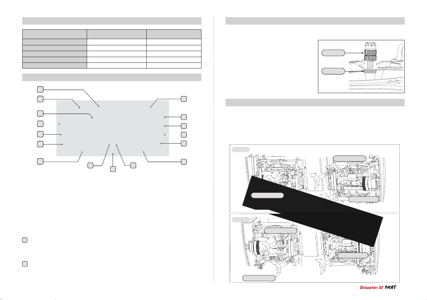
8. ADJUSTBLE STICK TENSION
The mz-12 offer s a d j u stable ten s i o n o n t h e t h r o t tle, aile r o n, e l ev at o r a n d r u d d e r s t i c ks .
1. Remove the batter y cover and battery form the transm itter
2. Unscrew the six Philips head screws that hold the transmitter’s rear cover and remove the rear case.
3. Using a P hilips screw driver, adjust the stick tens ion scre w for the desired control. Clockwise to
tighten and counter clockwise to loosen.
Model 1
Elevator tension
Aileron tension
Model 2
Aileron tension
Elevator tension
Rudder tension
Rudder tension
Frequency band
Modulation
Output power
Current drain
Operating voltage
Transmitter mz-12
2.4~2.4835GHz
FHSS
100mW
Approx 125mA
3.4V~6V
Receiver GR-16
2.4~2.4835GHz
FHSS
-
Approx 70mA
3.6V~8.4V
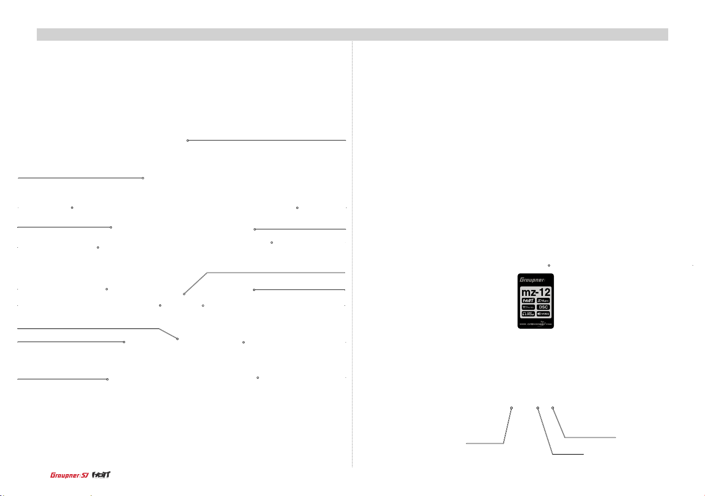
6. DISPLAY EXPLANATION
2
1
16
15
14
13
12
10
1. Receiver signal indicator
- Function Help
2
10
2. Button Lock status
3. Battery voltage of receiver
4. Timer
5. Flight timer
6. Trainer indicator
7. Q. LINK
8. Aileron trim
Butto n Lo ck funct i o n
This function is used to prevent from pressing buttons accidently during ight.
Press bo t h of TLM and VI E W b u ttons at th e s a m e t i m e t o l o c k t h e b u ttons. If yo u p r e s s b o t h
of TLM and V I EW butto n s a t t h e s am e t i m e a g a i n, t h e l o ck funct i o n i s t u rned of f.
Transmitter type
- NR (Nor m a l) : When tra ns m i tter is op e r at e d i n t h e n o r m a l m o d e
- T.T ( Trainer) : When t r a n s m itter is op e r a te d i n t h e t r a i n e r m o d e
If Jack se l e ct progr a m m in g i s s e t to D S C a t B as i c s ett, the r e i s no d i s p l ay
911
9. Throttle trim
10. Transmitter type
11. Elevator trim
12. Rudder trim
13. Model type
14. Battery voltage of transmitter
15. Model name and model memory
16. Model type
3
4
5
6
7
8
5
Page 6
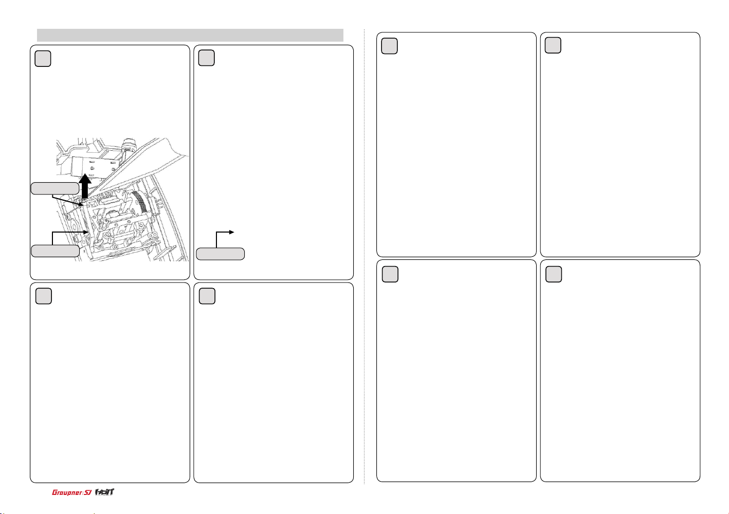
9. Mode exchange of throttle stick for Mode 1 and Mode 2
1
Unscrew the transmitter’s rear case and
remove the rear case and disassemble the
tension spring from the centering cam in the
elevator gimbal of mode 1 transmitter with
tweezers
Tension spring
2
Disassemble the centering cam form
the gimbal
5
Unscrew the tension spring control bolt in
the elevator gimbal of mode 1 transmitter
6
Screw the disassembled bolt from the
throttle gimbal of mode 1 transmitter into the
elevator gimbal to x the controller
Centering cam
3
Unscrew the tension spring control bolt in
the elevator gimbal of mode 1 transmitter
6
Centering cam
4
Disassemble 2pcs of leaf spring in the
throttle gimbal of mode 1 transmitter
7
Assemble 2pcs of disassembled leaf
spring from the throttle gimbal of mode 1
transmitter into the elevator gimbal and adjust
the bolt for the desired control
8
Assemble the disassembled centering
cam form the elevator gimbal of mode 1 transmitter into the throttle gimbal pin
Page 7
9
Assemble the centering cam into the
throttle gimbal of mode 1 transmitter and set
the spring in the center control part and the
centering cam with tweezers
10
Screw the disassembled tension control bolt from the elevator gimbal of mode
1 transmitter into the throttle gimbal and
adjust the bolt for the desired control
Tension spring
Assemble the transmitter’s rear case and switch to mode 2 from mode 1 at Stick mode page in
the transmitter programming setup section according to the manual.
10. WHAT IS HoTT
HOPPING TELEMETRY TRANSMISSION(HoTT)
it is Graupner/SJ’s unique telemetry tech n o l o g y i n
2.4GHz signal protocol that support Bi directional
data transmission gives user real-time information on
things like user model’s RPM, Voltage, Temperature,
User programmed warning, and etc. The use of up to
75 channels ensures extreme operating reliability and
immunity to external interference thanks to optimized
frequency hopping broad channel sequence.
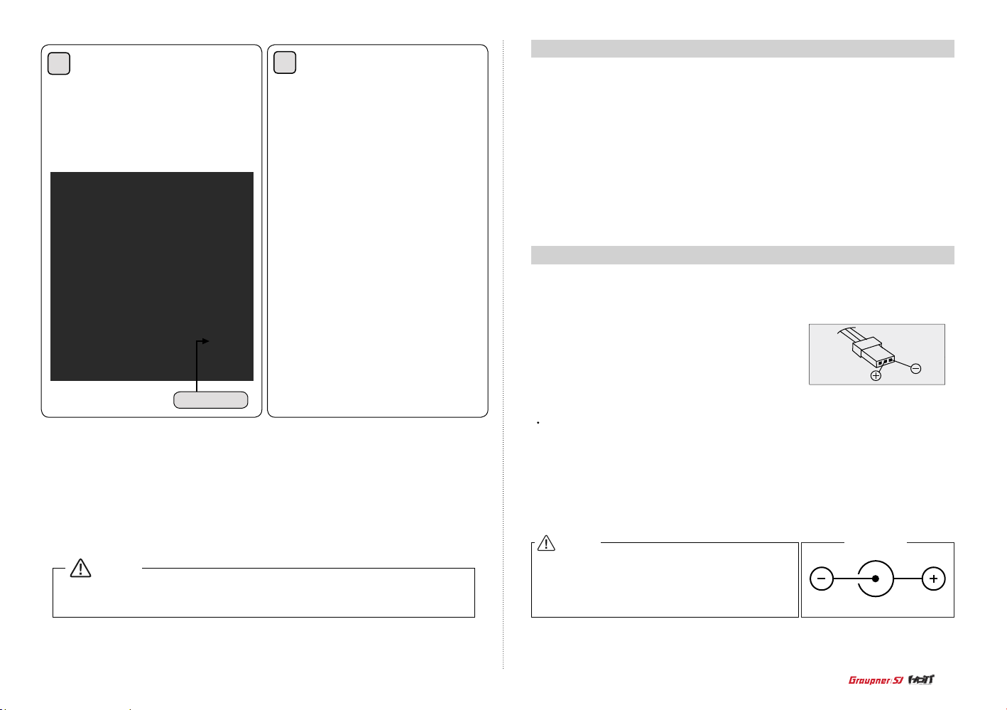
11. BATTERY INSTALLATION
Optional NiCd or NiMH 1.2-volt AA rechargeable 4-c ell batteries can be used. A battery conn ecter
is on the in s i d e of t h e t r a n s m i tter for c o nve n i e nt r e c h a r g i n g. Graupne r/ SJ offe r s r e c h a r g e a b l e
NiCd, NiMH batteries, part number S22331.
Remove the battery cover and install the battery pack
ensuring the polarity of the battery connecter.
CHARGING BATTERIES
The included charger is designed to recharge your batteries at a rate of 150mA. Do not use this charger
for equipment other than Graupner/SJ transmitters that use 4-cell battery packs. The charging plug
polarity may not be the same and equipment damage can result. During the charging operation, the
charger’s temperature is slightly elevated. This is normal.
NOTICE
Make sure to test all functions are normally operated in mode 2 before ying
CAUTION
Charge only rechargeable batteries. Non-rechargeable
batteries may burst causing injury to persons and/or damage to property. Never leave charging batteries unattended.
The mz-12 is comp at ib le w i t h al l cu r r en t Graupner/SJ A i rc r aft rece i ver s ( R S e r ie s )
Graupner/SJ
Transmitter Charge Jack Polarity
7
Page 8
12.
BINDING
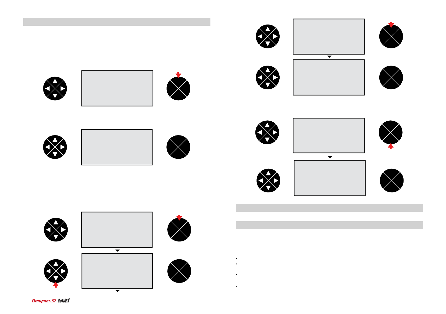
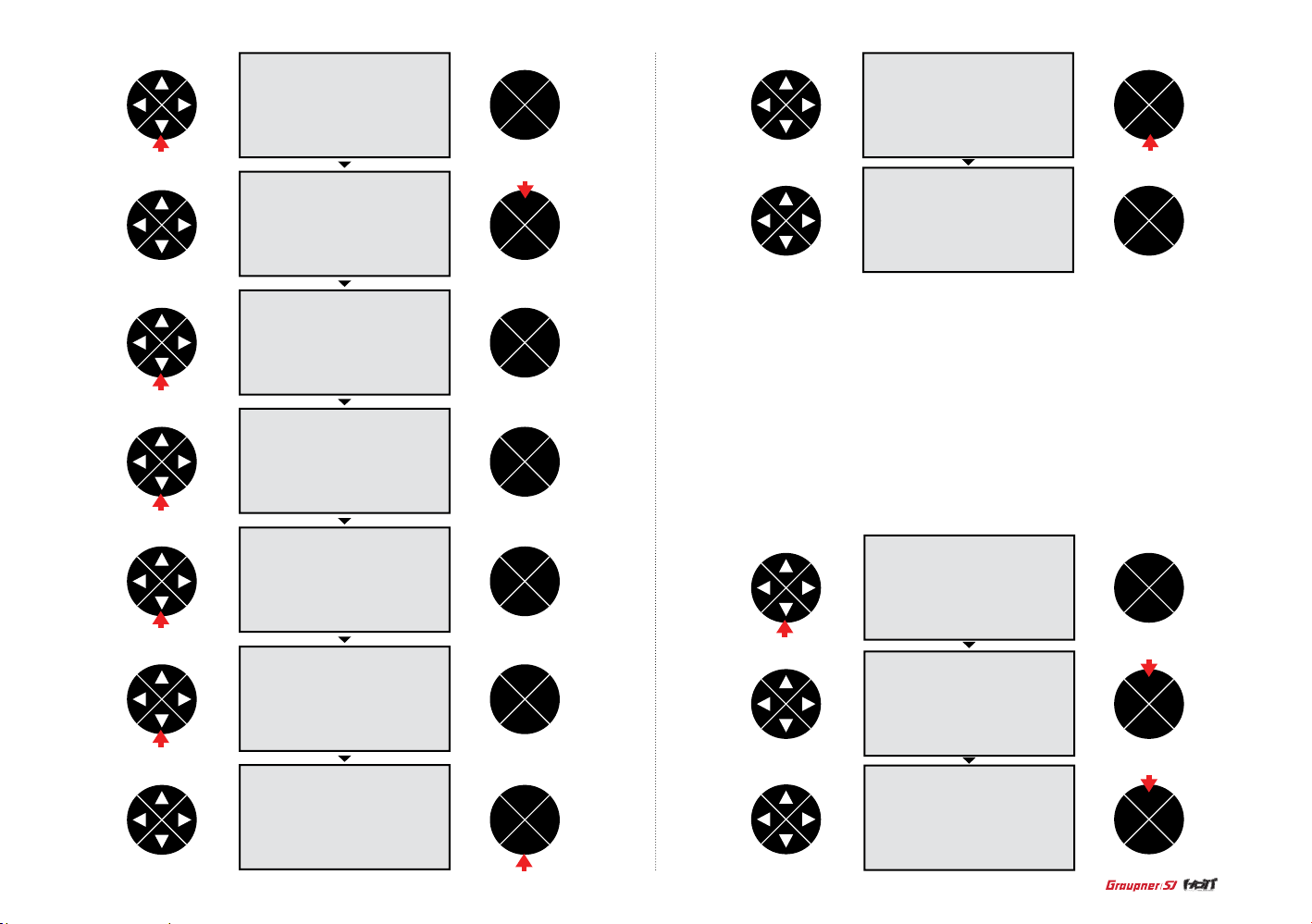
You must bind the r e c ei ve r to t h e tr a ns mi t te r b ef or e t he r ec e i ve r wi ll o p er at e. B in di n g te ac h es
the rec ei ve r th e s pe c i f i c c od e of t h e tr a ns mi t t er s o t ha t it w il l o nl y c o nn ec t t o it’s corr es p on d ing transmitter.
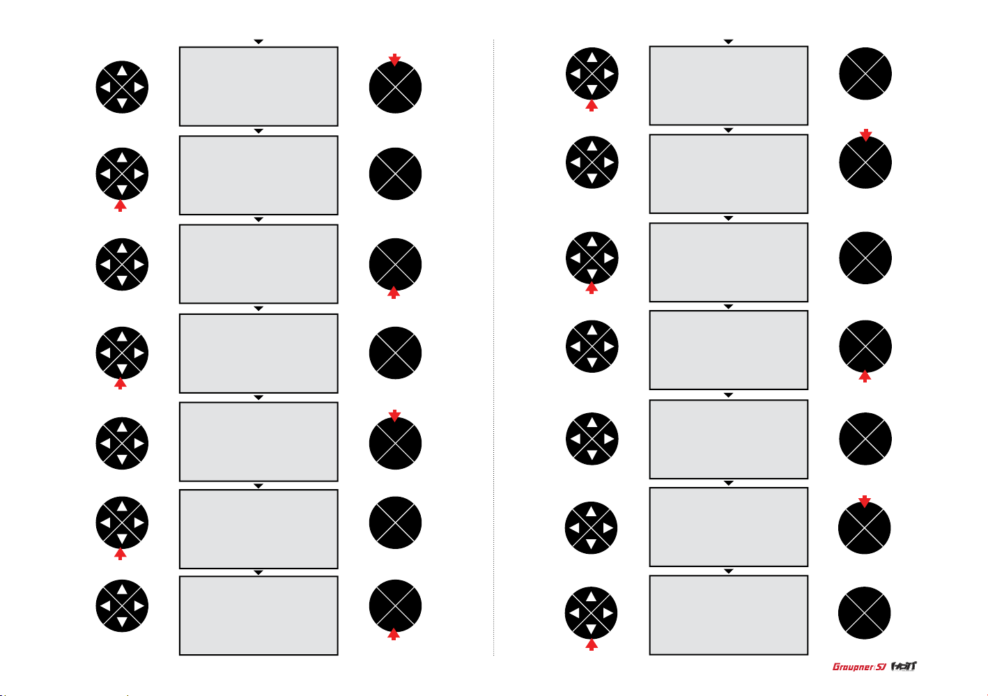
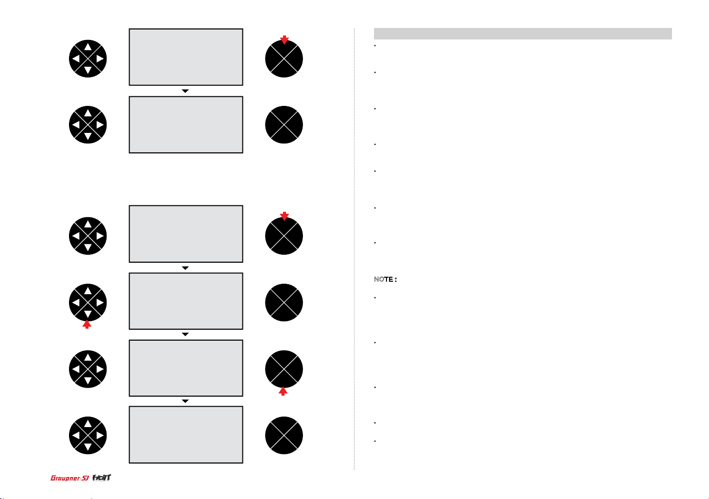
1. With the t ransmitter on and the home screen displayed, press the ENT butto n .
press
ENT
TEL VIW
ESC
press
ENT
TEL VIW
ESC
2. The mo del men is highlighted then press the direction button to highlight RF sett.
ENT
TEL VIW
ESC
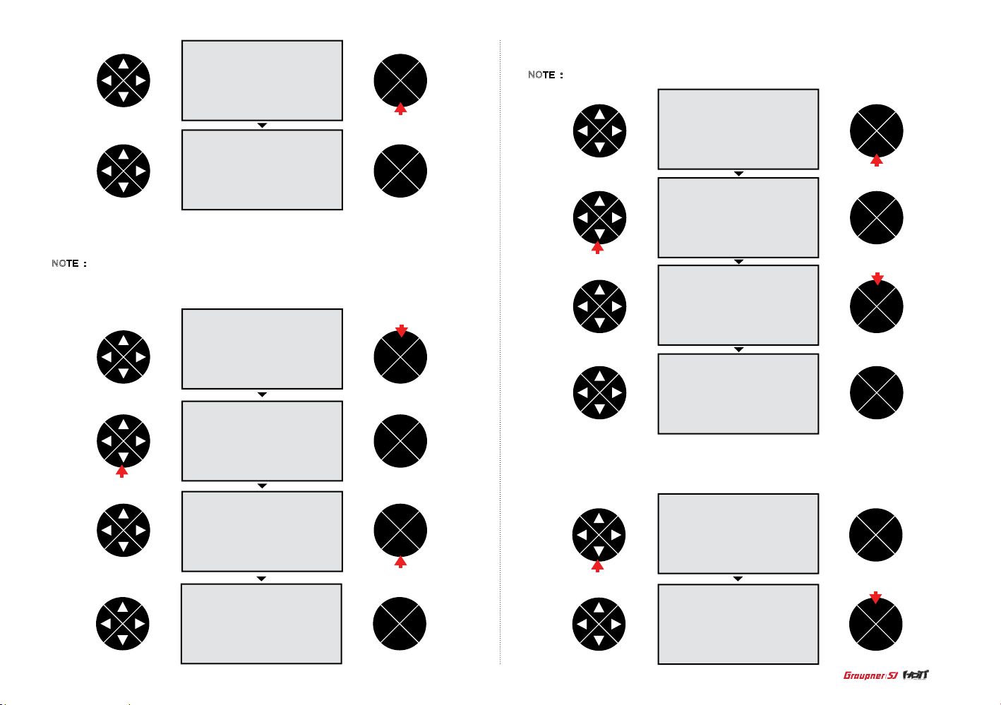
3. Press the ENT button, the cursor i s automatically o n the stic k mode line t hen pres s the direction
butto n to select the hyphen in the rx bind line. Turn on the receiver then press the ENT button on the
recei v er for over 3 seconds s o that the receiver enter the binding mode. Press the ENT button of the
transm itter, the sys t em will be c onnected within a f e w seconds and the model name o f the rece iver
is displ ay ed on the screen.
press
ENT
TEL VIW
ESC
ENT
TEL VIW
ESC
press
8
ENT
TEL VIW
ESC
4. After compl eting the bind, press the ESC button to return to the home scr een.
ENT
TEL VIW
ESC
press
ENT
TEL VIW
ESC
•
The Transmitter Programming Setup
1. Model mem (Aircraft and Helicopter)
The model mem (model memory) contains 4 categories: select model, model name, clear
model and copy model.
Select model :
It is used to add or select model of the already set 10 models.
Model name : The Model Name function allows you to name a model. This makes identifying and
selecting models much easier.
Clear model : Clear Model is used to remove the programmed model you will no longer be ying. No
other model memories will be affected.
Copy mod->mod : Copy model function copies the currently selected model’s programmed value to
another model list.
Page 9
press
ENT
TEL VIW
ESC
ENT
TEL VIW
ESC
press
press
ENT
TEL VIW
ESC
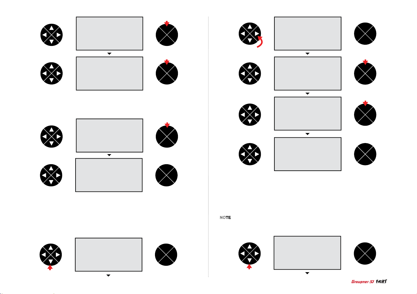
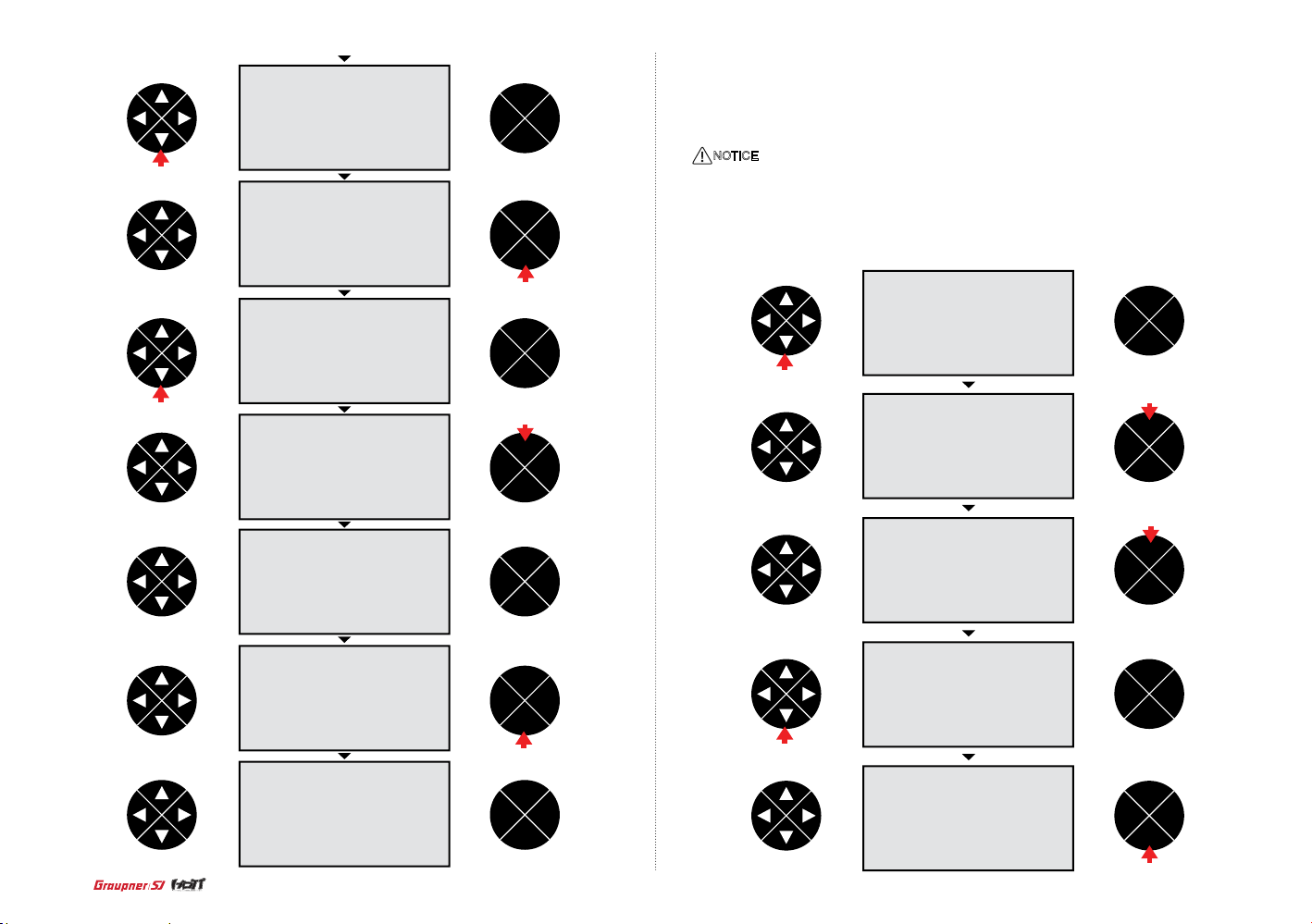
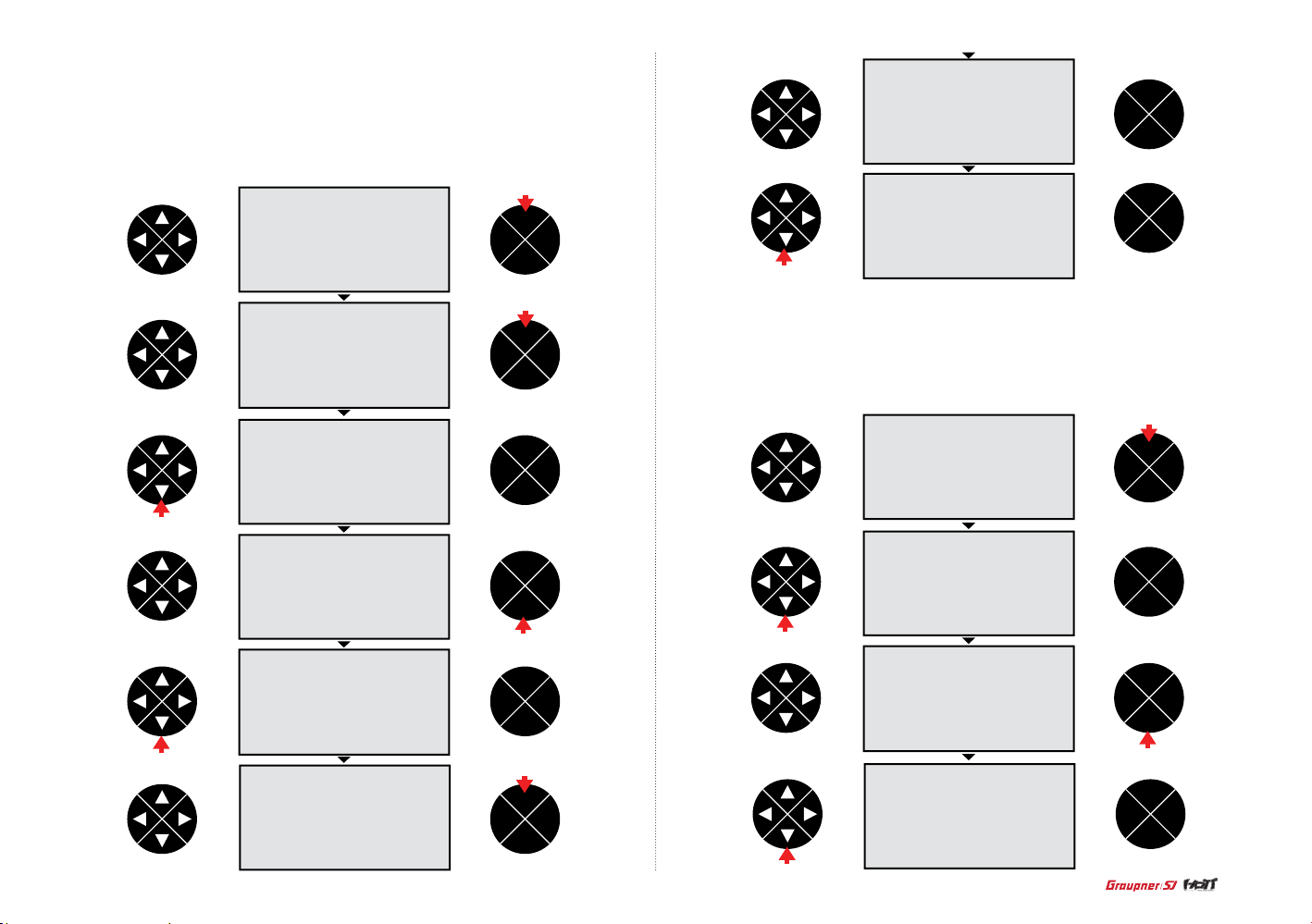
- Select model
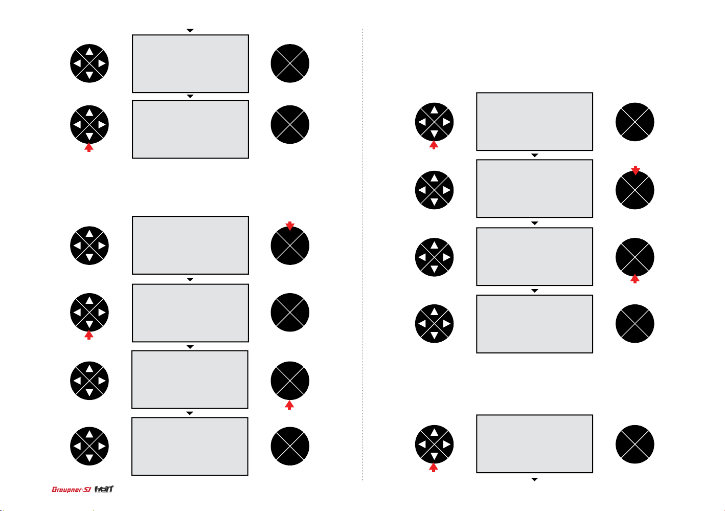
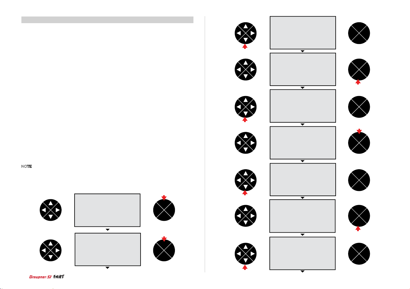
In the home screen, press the ENT button then the model mem is highlighted. Press the ENT button
to access the function.
press
ENT
TEL VIW
ESC
ENT
TEL VIW
ESC
Press th e d i re ction bu tton to sel e ct the mod e l t h e n p r e s s t h e E N T bu tton to ac cess the S e l
model t y p e s creen. Pr e s s t h e d ir e ction bu tton to hig h l i gh t t h e d e s i re d m odel ty p e (Aircra ft or
Helic o p te r) t h e n p ress the EN T b utton to se l e c t t h e m o d e l type. Th e h o m e s c r e e n i s di s p l aye d
and the po p u p m e s s a g e “Bind N /A w i t h t h e h i gh l i g ht on OK” ap p e a r s then pre s s t h e EN T b u tton
to bind. Th e rx bind screen aut o m at i cally ap p e ars then you m ay b i n d t h e t r a n sm i tter to the
recei ve r a c cordin g to t h e b i n d p r o cedure.
press
ENT
TEL VIW
ESC
press
ENT
TEL VIW
ESC
ENT
TEL VIW
ESC
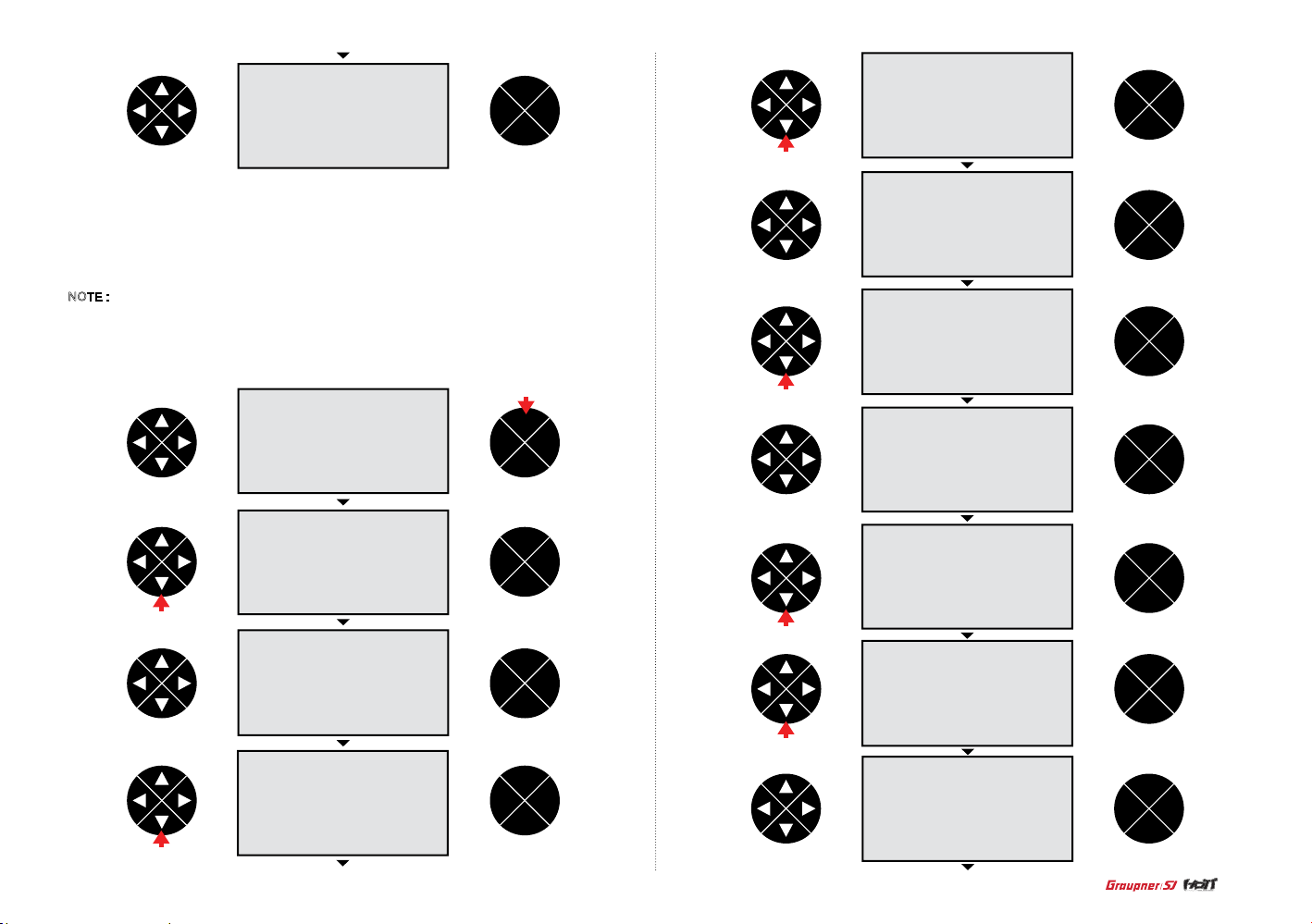
- Model name
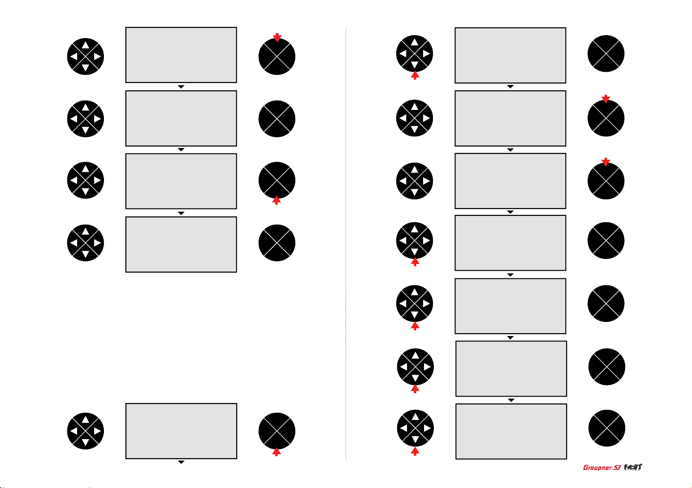
When the model me m i s h ighlight ed, press the ENT button the n t h e cursor i s on the select mode l
line. Pre ss the direction b utton to select the mod name l ine then press the ENT butto n t o acces s t o
the function. Press the direction button to highl ight the desired characte r then pre ss the ENT button
to acce pt. Repeat the process until completing. The name wil l display on the model name line.
Press the ESC butt on to get back to the model mem scr een.
NOTE : Pressing the direction button to hig h light the b lank and pr essing the ENT but t on will er a se
the current character.
press
ENT
TEL VIW
ESC
ENT
TEL VIW
ESC
press
9
Page 10
press
ENT
TEL VIW
ESC
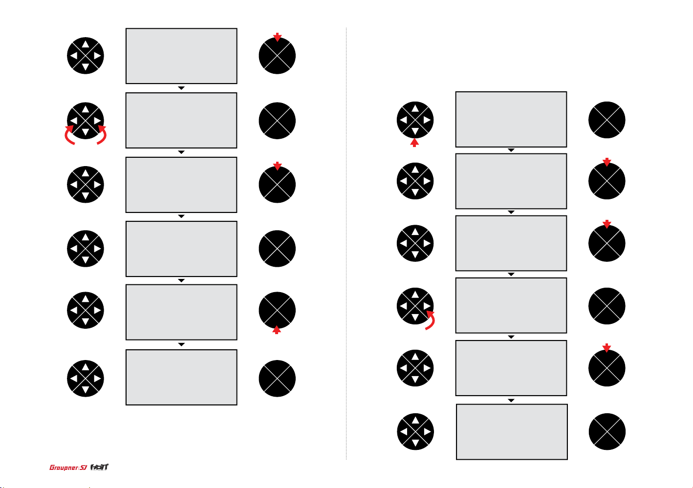
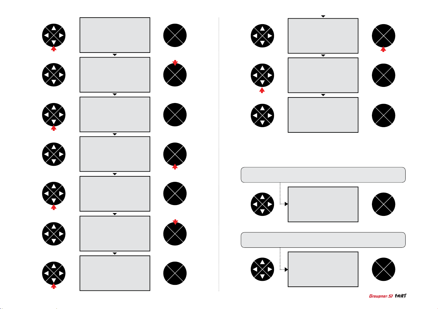
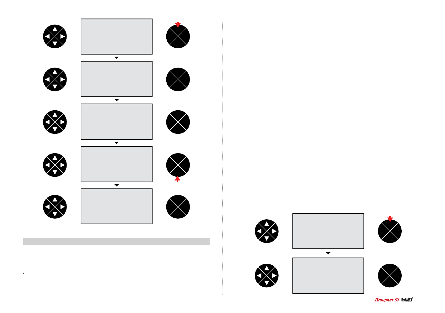
- Clear model
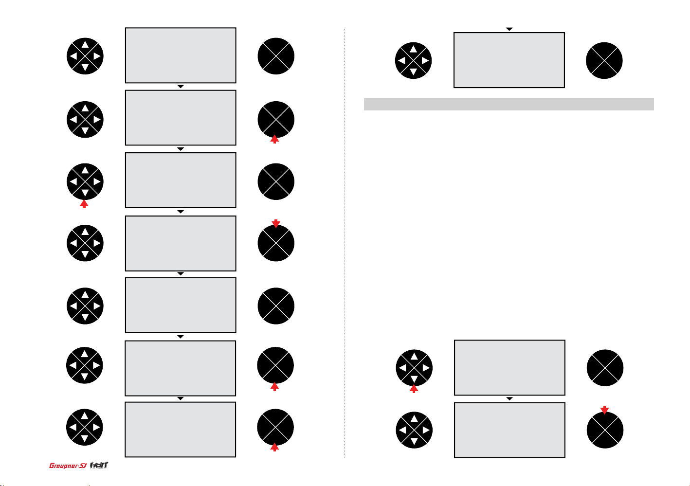
When the model me m i s h ighlight ed, press the ENT button the n t h e cursor i s on the select mode l
line. Pre ss the direction button to select the clear model line then press the ENT button to acces s to
the function. Pr ess the directio n b u tton to hi g h l ight the mo d el that you w i s h t o clear th e n p r ess the
ENT but to n . T h e p opup mes s a g e “YES or N O ” a p p e a rs on the sc r e e n . P r e s s t h e d i r e ction bu tton
to highlight YES th e n p r ess the EN T b u tton to cl e a r the mode l. The scre e n will return to the mo d e l
mem screen.
press
ENT
TEL VIW
ESC
press
ENT
VIW
TEL VIW
ESC
VIW
ENT
TEL VIW
ESC
ENT
TEL VIW
ESC
press
ENT
TEL VIW
ESC
press
press
ENT
ENT
TEL VIW
ESC
press
ENT
TEL VIW
ESC
press
ENT
TEL VIW
ESC
ENT
TEL VIW
ESC
press
ENT
TEL VIW
ESC
10
ENT
TEL VIW
ESC
Page 11
- Copy mod->mod
The model mem is highlighted in the menu screen then press the ENT button. T he cursor is on the
selec t model line. Press t he direction button to sel ect the copy mod ->mod line then press the ENT
butto n to a ccess to the func t i o n . W h e n the copy f r o m m o d el scree n a p p e a r s , p r e ss the dire ction
butto n to highli ght the model you want to copy then press the ENT button to accept. When the copy
to model s creen ap pears, press the directi on butto n to highli ght the mod el memory to copy t o then
press t he E N T b u tton to accept. Th e m e s s a g e “to be co p i e d YES or NO” a p p e ars on the sc r e e n .
Press the direction button to highlight YES then press the ENT button to complet e to copy. The copy
mod ->mod is autom atical ly displayed. If you press the ENT button after selecting the select mode l
line the n you may check the co pied mod el.
ENT
TEL VIW
ESC
press
ENT
TEL VIW
ESC
press
ENT
TEL VIW
ESC
press
press
press
ENT
TEL VIW
ESC
press
ENT
TEL VIW
ESC
press
ENT
TEL VIW
ESC
ENT
TEL VIW
ESC
press
ENT
TEL VIW
ESC
ENT
TEL VIW
ESC
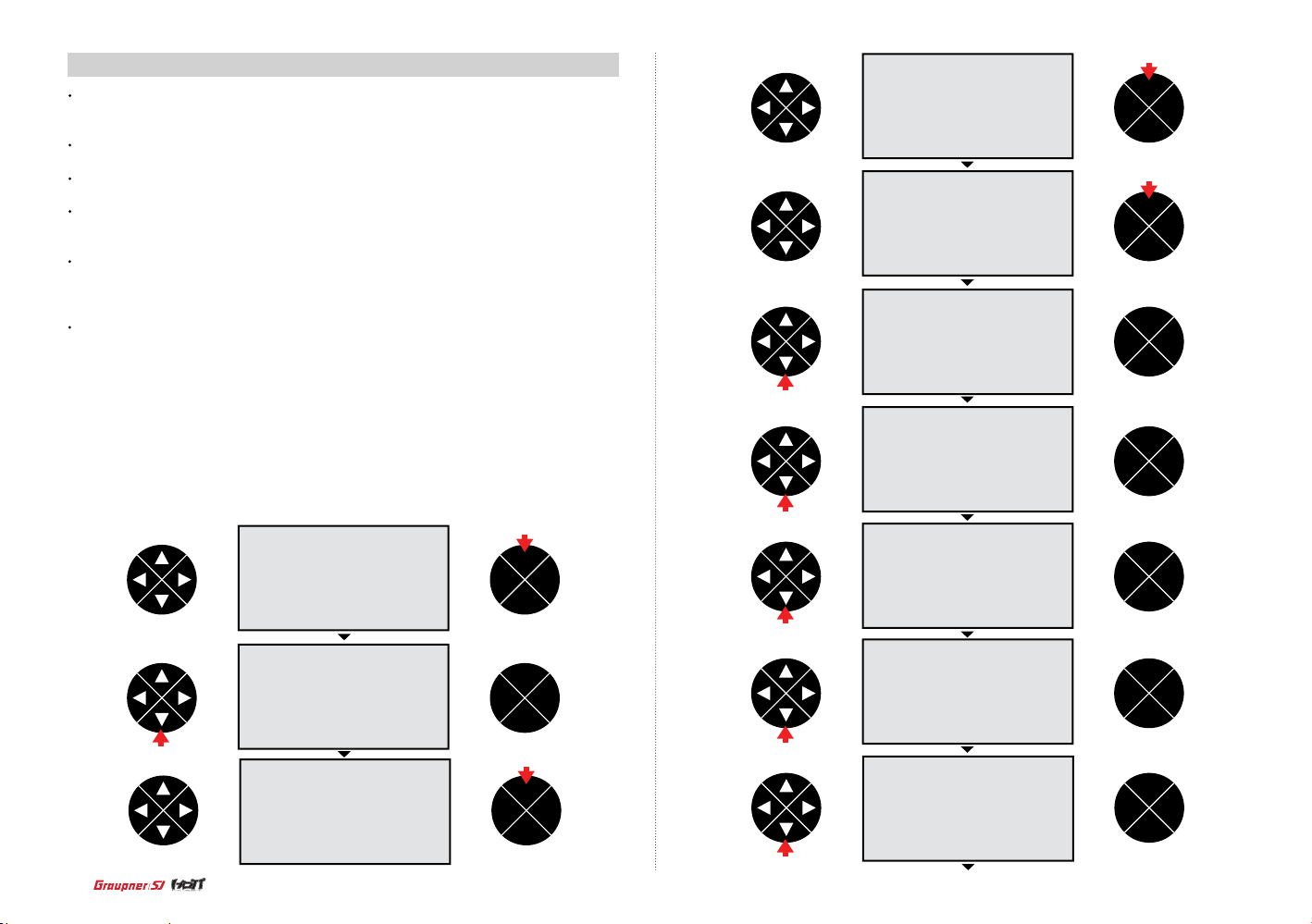
2. m.type + quick (Aircraft)
The m.type+qui ck function allows to program the various functio n of Airplane and Helicopter model.
Always choose model ty pe (Airc raft or Helicopter) before programming any other function of the
selec ted model type. The function that can be programmed is diff erent dep ends on the model t ype,
Aircraft or Helicopter.
•
Motor at C1 : Use the motor at C1 function to set the direction of the throttle channel in the Aircraft
and program to use the throttle channel as the brake in the glider.
•
Tail type : Use the Tail type functions to program the tail mix to match your airplane. 4 tail types (nor-
mal, V tail, delt/w, 2elev sv appear) are available.
•
Aile/ap : Use the Aile/ap functions to program aile/ap mix to match your airplane 5 aile/aps (1aile,
1aile 1ap, 2aile, 2aile 1ap, 2aile 2ap) are available.
•
Quick link set : The quick link sett function allows to adjust the D/R expo value and assign the cor-
responding switch to cope with the unexpected situation such as the ight with the strong wind. Since
the adjusted value is activated by moving the switch, you can cope with the crisis with just one switch.
It makes you operating the ight much easier. You can select take off , thermal , dist , speed , acro ,
landing , air-tor , test at quick2 and quick3.
•
Quick link trim : Use the quick link trim function to program the appropriate trims of the quick 2 and
quick 3 in the quick link. The user can program the trim in advance to cope with the unexpected situation
such as the ight with the strong wind and match the ight situation of the takeoff , thermal and speed
of the glider. If the switch is ON, the corresponding trim is activated so the user do not need to set these
trims every time.
NOTICE : The programming value of the quick link trim depends on the motor at C1, Tail type, Aile/ ap
11
Page 12
With th e transmitter and the home s creen displayed, press the ENT button. Press t he direction button to highlight th e m.type quick then press th e ENT butt on to access. The model ty pe is sele cted
then press the ENT button to select the motor at C1. Press the ENT button a gain to hig hlight th e
value in the motor at C1 then press the direction button to select the desired v alue. 4 values ( no,
no/inv , idel re, idel fr) as explained below are available.
press
ENT
TEL VIW
ESC
ENT
TEL VIW
ESC
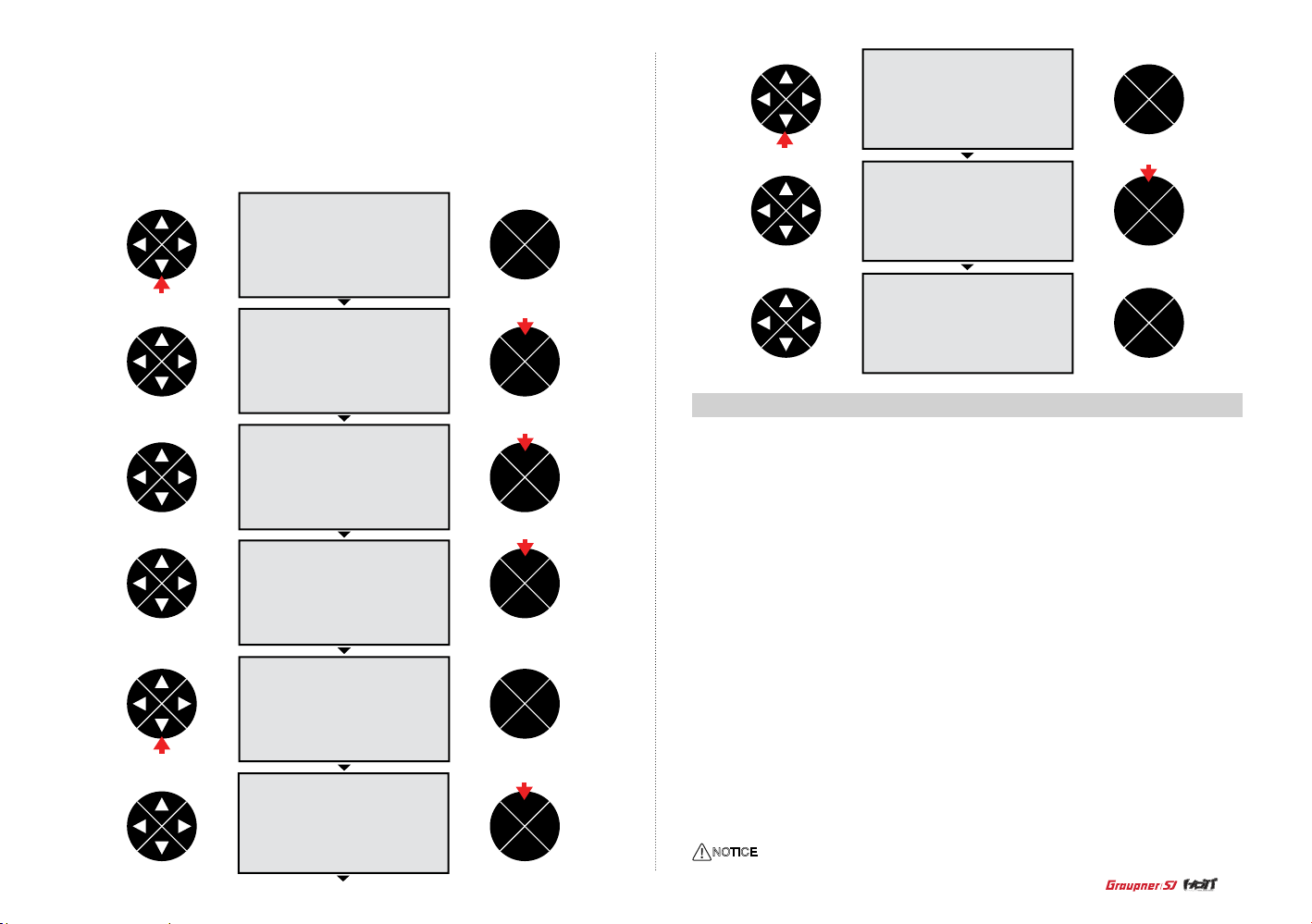
- Motor at C1 no
It creates the air b rakes using aile/ ap. When the C1 (The throttle channel) is moved, 1~3 air b rakes
that the u ser prog rammed is created . The value of the creat ed air brake w ould be programm ed, the
air brake function works according to the throttle stick’s movement from the high to the lower position.
When the throttle stic k moves to the h igh position, the air brake channel is in the neut ral, when it
moves to low position, the air brake work s proportionately to th e throttle stic k’s movement according
to the programming.
ENT
TEL VIW
ESC
- Motor at C1 no/inv
It is contrary to ”no”. When the thrott le stick m o v es to the low position, the air b rake channel is in
the neutral, whe n it moves to high posit ion, the air brake works proportionately to the throttle sti ck’s
movement according to the programming.
12
press
press
ENT
TEL VIW
ESC
press
ENT
TEL VIW
ESC
press
ENT
TEL VIW
ESC
ENT
TEL VIW
ESC
ENT
TEL VIW
ESC
press
ENT
TEL VIW
ESC
- Motor at C1 idel re
The idle position of the throttle stick (C1) is back, toward the user, if the throttle stick is not there, the
throttle warning message “Throttle too high” appears and the cut off option is activated.
ENT
TEL VIW
ESC
press
1 time press
ENT
TEL VIW
ESC
Page 13
- Motor at C1 idel fr
The idle position of the throttle stick (C1) is forward, away from the user, if the throttle stick is not
there, t he throttle warning message “T hrottle too high” appears and the cu t off option is activated.
ENT
TEL VIW
ESC
WARNING : Ensure that any internal-combustion engine or electric motor shouldn’t be running
accidentally during the programming process.
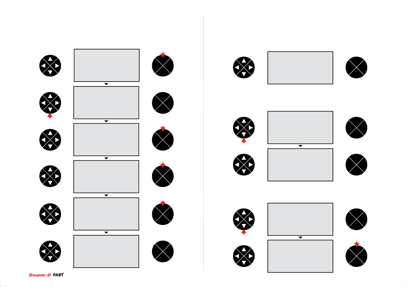
- Cut off
When the option of “idle re” or “idle f r” is selected, the cut off option is activa ted. It tur ns off th e
intern al combu stion engine or the electric motor.
Press the ENT but ton to remove the highl ight of the motor at C1 valu e then press the direction button to select the cut off line. Press t he ENT but ton to high light -100% of the cut of f v alue then press
the direction button to adjust the value. Press the ENT bu tton to re move the hig hlight
NOTE : The value of -100% is the cut off position the user can program, if the cut off value is programmed less than -100%, the breathing hole of Engine carburetor is block or the speed controller make
the motor off so the power is not delivered to the airplane.
press
ENT
TEL VIW
ESC
Press the direction button to sel ect the value,+150%,. Place the throttle stick at the desired position
and press the ENT button th en the adjusted value is applied (The adjusted value is activated when
the throttle stick is in that position).
NOTE : the v alue,+150%, is the throttle stick position where the cut off function is activated.
press
ENT
TEL VIW
ESC
ENT
TEL VIW
ESC
press
press
ENT
TEL VIW
ESC
press
ENT
TEL VIW
ESC
press
ENT
TEL VIW
ESC
ENT
TEL VIW
ESC
press
press
ENT
TEL VIW
ESC
ENT
TEL VIW
ESC
Press the direction button to sel ect the hyphen then press the ENT button. The popup mess age
“push desired switch into positio n on” appea rs then move the switch to the desired position (The cut
off function is activated when the switch is moved to that position)
ENT
TEL VIW
ESC
press
13
Page 14
press
ENT
TEL VIW
ESC
ENT
TEL VIW
ESC
press
ENT
TEL VIW
ESC
ENT
TEL VIW
ESC
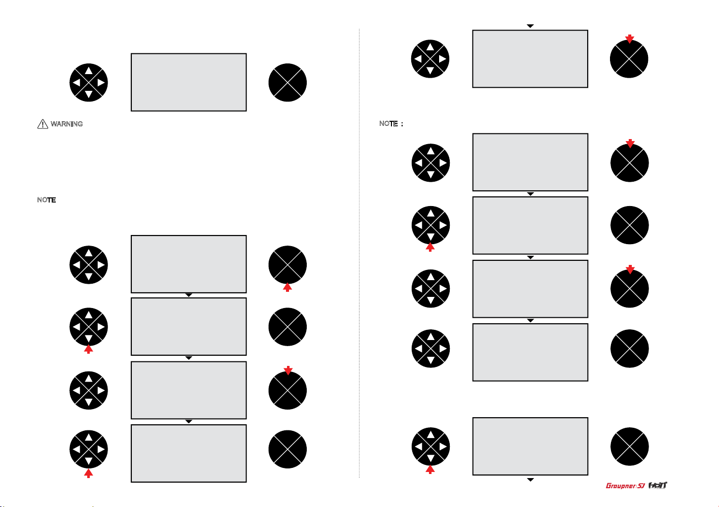
- T ail type
Use the Tail ty pe functions to program the tail mix to match you r airpla ne. 4 tail types (normal, V
tail, delt/w, 2elev sv appear) are available. The correct value should be matched each ot her sinc e
the some v alue is not m atch to the others, r efer to the below tab le.
Press the direction button to sel ect the tail type line then press the ENT button to highl ight the
value. Press the direction button to choos e desired value then press th e E SC butto n to remove the
highli ght. Press the ESC button again to retur n to the previous screen.
ENT
ENT
TEL VIW
ESC
press
press
ENT
TEL VIW
ESC
ENT
TEL VIW
ESC
press
ENT
TEL VIW
ESC
press
press
ENT
TEL VIW
ESC
ENT
TEL VIW
ESC
- Aile/ ap
Use the Aile/ ap functions to p rogram aile/ap mix to m atch your airplane. 5 aile/aps (1aile, 1aile
1ap, 2aile, 2aile 1ap, 2aile 2ap) are available. The c orrect value sh ould be matched each other
since t he some val ue is not match to the others, refer to the below table . Press the direction button
to selec t the aile/ap line then press the ENT button to highlight the value. Press the direction
butto n to choos e desired value then press th e E SC butto n to remove the highlight. Pres s the ESC
butto n again to return to the previous screen.
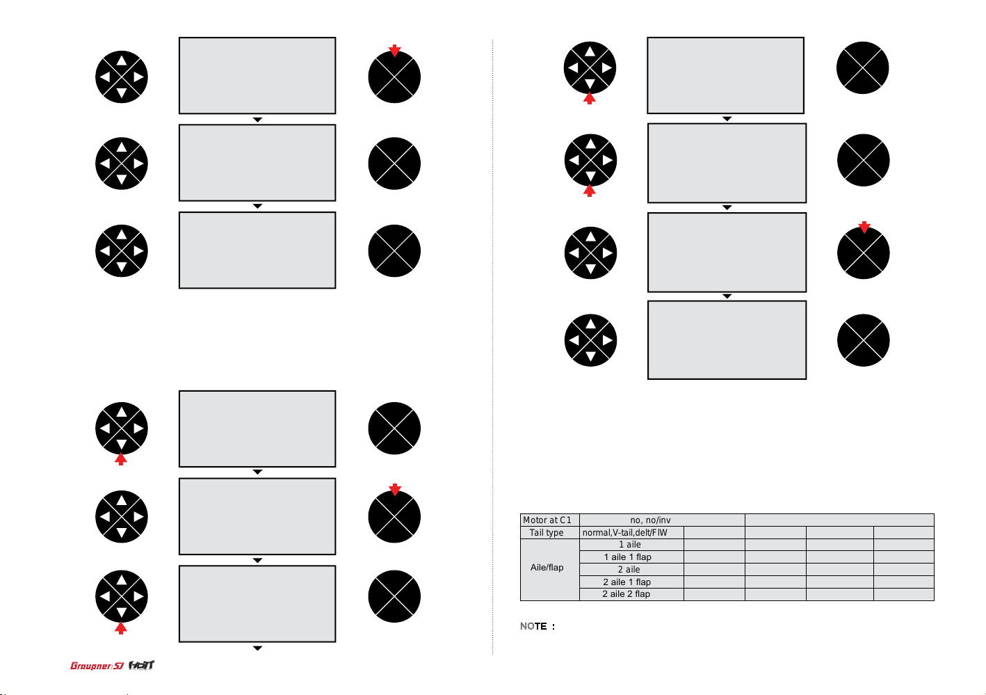
Motor at C1
Tail type
Aile/ap
normal,V-tail,delt/FlW
no, no/inv
1 aile
1 aile 1 ap
2 aile
2 aile 1 ap
2 elev sv
1 aile
1 aile 1 ap
2 aile
2 aile 1 ap
normal,V-tail
1 aile
1 aile 1 ap
2 aile
2 aile 1 ap
Idle re, idel fr
Delt/FlW
2 aile
2 aile 1 ap
2 aile 2 ap
2 elev sv
1aile
1 aile 1 ap
2 aile
2 aile 2 ap
NOTE : The corre c t va l u e s h o u l d b e ma t c h e d e a c h other since the som e va l u e i s n o t ma t c h to
the othe r s , r ef e r t o t h e t a b l e.
14
Page 15
press
press
press
ENT
TEL VIW
ESC
press
ENT
TEL VIW
ESC
ENT
TEL VIW
ESC
ENT
TEL VIW
ESC
ENT
TEL VIW
ESC
press
ENT
TEL VIW
ESC
- Quick link sett
The quick link set t function allow s t o adjust th e D /R expo value and assign the co rresponding
switch to cope with the unexpected situation such as the ight with the strong wind. Sinc e the
adjuste d v alue is activated by moving the sw itch, you c an cope with the crisis wi th just one switch.
It makes you operating the ight much easie r. You can select take of f, therm al, dist, speed, acro,
landing, air-tor, test at q uick2 a nd quick3.
Press the direction button to sel ect the quick link sett then press the E NT butto n t o a ccess the
funct ion. Pres s the direction button to se lect the q u cik2 li ne or the qui ck3 line t hen pres s the ENT
butto n t o h ighligh t the value. Press the directi on butto n t o select the desir ed value (take o ff, thermal, dist, speed, a cro, landi ng, air-tor, test at quick2 and quick3). Press the ENT button to rem ov e
the high light the n press th e d irecti on butto n t o select the hyphen . If you pres s the ENT button, the
popup message “push desired switch into position on” appears. Move the switch to the desired
position then t he corr espondi ng value appears. Pr ess the ESC b utton to g et back to the m .type +
quick screen then the quick link programming is completed.
press
press
ENT
TEL VIW
ESC
ENT
TEL VIW
ESC
ENT
TEL VIW
ESC
press
press
ENT
TEL VIW
ESC
press
ENT
TEL VIW
ESC
press
ENT
TEL VIW
ESC
15
Page 16
press
ENT
TEL VIW
ESC
ENT
TEL VIW
ESC
- Quick link trim
Use the quick link trim function to program the appropriate trims of the quick 2 and quick 3 in the quick
link. The user can program the trim in advance to co pe with the unexpec ted situation such as the ight
with the strong wind and match the ight si tuation of the takeoff , ther mal and speed of the glider. If the
switch is ON, the corresponding trim is activated so the user do not need to set these trims every time.
NOTICE: The programming value of the quick link trim depends on the motor at C1, Tail type, Aile/ ap
Here is an example in case of motor at C1 (no) , tail t ype (norm al) , aile/ ap (2aile 2ap) at the model
type Press the ENT button to access the function. The cursor is on the FLA value in the normal line
then press the ENT and the direction buttons to highlight and adjust the desired value. Press ENT
button and direction button to remove the highlight and select the AIL value. The AIL value and ELE
value can be adjusted in the same method with the FLA programming.
16
press
1 time press
ENT
TEL VIW
ESC
press
ENT
TEL VIW
ESC
ENT
TEL VIW
ESC
ENT
TEL VIW
ESC
press
ENT
TEL VIW
ESC
ENT
TEL VIW
ESC
press
press
ENT
TEL VIW
ESC
press
ENT
TEL VIW
ESC
ENT
TEL VIW
ESC
press
ENT
TEL VIW
ESC
press
Page 17
press
ENT
TEL VIW
ESC
press
ENT
TEL VIW
ESC
ENT
TEL VIW
ESC
press
ENT
TEL VIW
ESC
press
press
press
press
ENT
TEL VIW
ESC
ENT
TEL VIW
ESC
press
ENT
TEL VIW
ESC
press
ENT
TEL VIW
ESC
ENT
TEL VIW
ESC
ENT
TEL VIW
ESC
After comple ting the normal quick link ad justment, press t he direction button to sel ect the th ermal
quick li n k line. The t hermal quick link a nd speed qu ick link can be programmed in the same method. If you al ready set the quick li nk switch a nd the swit ch is ON, the cursor is automa ticall y moved
to the co rrespo nding qui ck link valu e .
- thermal quick link의 스위치를 ON하면 표시줄이 normal에서 ther-
If the thermal quick link switch is ON, the cursor is moved to the
mal로 이동하며 ON 되어 있음을 알려줍니다.
thermal quick link and the user can check the thermal quick link is ON
ENT
TEL VIW
ESC
- thermal quick link의 스위치를 ON하면 표시줄이 normal에서 ther-
If the speed quick link switch is ON, the cursor is moved to the speed quick link
mal로 이동하며 ON 되어 있음을 알려줍니다.
and the user can check the speed quick link is ON
ENT
TEL VIW
ESC
17
Page 18
2-1. Model type (Helicopter) : 5 functions are available
Swashplate
Use the swashplate function to set the swahplate type to match your Helicopter model.
It supports 6 value (1servo, 2 servo,3sv(2rol),3sv(140),3sv(2nic),4sv(90))
Cut off
The cut off function allows to turn off the internal combustion engine or the electric motor.
Rotor direct
Use the rotor direct function to set the rotation direction of the main rotor.
Pitch min
Use the pitch min function to reverse the servo direction in all of pitch, elevator, aileron and throttle
channels, the default value is rear. Available settings are rear and front.
Aurtorotat
You may set the switch to be used as auto rotation. If the switch is on, throttle channel is hold at 90%
position and pitch, elevator and aileron that is connected to throttle channel are normal operated. It is
the same function with throttle hold.
Quick link sett
The quick link sett function allows to adjust the quick2 value and assign the corresponding switch to
cope with the unexpected s ituation such as the ight with the strong wind. Since the adjusted value is
activated by moving the switch, you can cope with the crisis with just one switch. It makes you operat-
ing the i ght much easier. You can select hover, acro, acro 3D, speed and test at the quic k2 line.
- Swash plate
With th e transmitter on a nd the hom e screen displayed, press th e ENT button. The transmitter
menu is di splayed. Pr ess the direction butto n to move the hi ghlight to the m.type quick then press
the ENT bu tton to access the m.type quick function . The cursor is on the model t ype line then pres s
the ENT bu tton to hi ghlight t he value. Press the direction butto n to the desired value i n the swashplate line then press the ESC button to remove the highlight
press
ENT
TEL VIW
ESC
press
ENT
TEL VIW
ESC
press
ENT
TEL VIW
ESC
ENT
TEL VIW
ESC
press
ENT
TEL VIW
ESC
press
ENT
TEL VIW
ESC
press
18
press
ENT
TEL VIW
ESC
press
ENT
TEL VIW
ESC
ENT
TEL VIW
ESC
press
ENT
TEL VIW
ESC
press
Page 19
ENT
TEL VIW
ESC
press
ENT
TEL VIW
ESC
- Cut off
Press the direction button to sel ect the cu t o ff line t hen press the ENT and the direction button to
highli ght and adju st the value less than -100%. Press the ESC button to rem ov e the highl ight.
NOTE : The v a lue of -100% is th e cut off p ositio n the user c an program, if the c u t o ff value is programmed less th a n -100%, the breathing h ole of Engine carburetor is block or the speed control ler
lets the m otor off so the powe r is not deliv ered to the Helico p t er.
press
ENT
TEL VIW
ESC
ENT
TEL VIW
ESC
press
Press the direction button to select +150% in the value. Place the throttle stick at the desired position and press the ENT button then adjusted value is applied (The adjusted value is activated when
the throttle stick is in that position).
NOTE : the value of +150% is the throttle stick position where the cut off function is activated.
ENT
TEL VIW
ESC
press
ENT
TEL VIW
ESC
press
press
ENT
TEL VIW
ESC
ENT
TEL VIW
ESC
Press th e d i r ection b u tton to se l e ct the hyph e n then pre s s the ENT button. The popup message“push desired switch into position ON”appears then move the switch to the desired position
(The c u t o ff func t ion is act i v at ed when the s witch is mo ve d t o that posi tion)
ENT
TEL VIW
ESC
press
ENT
TEL VIW
ESC
press
ENT
TEL VIW
ESC
press
ENT
TEL VIW
ESC
19
Page 20
ENT
TEL VIW
ESC
- Pitch min
Use the pi tc h m in f un c t io n to r eve r se t h e se rvo direc t i on i n a ll of p i tc h, e l evat or, ail er o n an d
throt tl e c h an ne l s, t he d ef au lt v al ue i s re a r. Availa bl e se t t in gs a r e re ar a nd f r o nt .
Press th e di re c t io n b utton to sel e c t th e p it h mi n l in e th e n pr e ss t h e EN T bu t t on t o hi gh l ig ht t he
pitch mi n val u e. Pr es s t h e di re c ti o n to s e le c t th e d es ir e d val u e (rea r or f r o nt) th en p r es s t h e
ESC butt on t o re mo ve th e h ig hl i gh t.
ENT
TEL VIW
ESC
press
- Rotor direction
Press the direction button to select the rotor direct line then press the ENT button to highlight the value. Press the direction button to select the right or left. Press the ESC button to remove the highlight.
press
ENT
TEL VIW
ESC
ENT
TEL VIW
ESC
press
ENT
TEL VIW
ESC
press
ENT
TEL VIW
ESC
press
press
ENT
TEL VIW
ESC
ENT
TEL VIW
ESC
press
ENT
TEL VIW
ESC
- Aurtorotat
Press the direction button to sel ect the autorotat l ine then press the ENT button. The pop up message “push desired switch into position ON” appears. Move the switch to the desired position then
the corresponding val ue appears. The autorotat f unction is activated when the switc h is moved to
that position. Press the ESC button to get back to the m.type + quick screen.
20
ENT
TEL VIW
ESC
ENT
TEL VIW
ESC
press
Page 21
press
ENT
TEL VIW
ESC
ENT
TEL VIW
ESC
ENT
TEL VIW
ESC
press
ENT
TEL VIW
ESC
press
press
ENT
TEL VIW
ESC
press
ENT
TEL VIW
ESC
ENT
TEL VIW
ESC
- Quick link sett
The quick link sett funct ion allows to adjust the quick2 value and assign the cor respon ding switch to
cope wi th the unexpected situation such as the ig ht with the strong wind. Since the adjusted va lue
is activ ated by moving the switch, you can cope with the cr isis wit h just one sw itch. It ma kes you op-
erating the ight much easier. You can select hover, acro, acro 3D, speed and test at the quick2 line
Press the direction button to sel ect the quick link se tt line then press the ENT button to ac cess th e
funct ion. The c ursor is on the default value, hov er, in the quick 2 line then p ress the E NT button to
highli ght. Press the dire ction button to select the desire d v alue then press th e ENT button to remove
the highlight. Press the directi on button to select the hyphen then press the ENT button. The popu p
message “push desired switch into position ON” appears. Move the switch to the desired position
then the correspondi ng value appears. Press the ESC button to get back to t he m.type + quick
screen. The quick link function is connected to the D/R expo and the heli mix functions so th e diffe rent value of the normal and quick2 ca n be programmed to t he D/R expo and the heli mix functions.
ENT
TEL VIW
ESC
press
ENT
TEL VIW
ESC
press
ENT
TEL VIW
ESC
press
ENT
TEL VIW
ESC
press
ENT
TEL VIW
ESC
press
21
Page 22
ENT
TEL VIW
ESC
ENT
TEL VIW
ESC
22
press
ENT
TEL VIW
ESC
press
ENT
TEL VIW
ESC
press
ENT
TEL VIW
ESC
ENT
TEL VIW
ESC
ENT
TEL VIW
ESC
press
ENT
TEL VIW
ESC
press
3. Servo sett (Aircraft and Helicopter)
The servo sett a djusts the servo reverse, c enter, travel for all six channels.
- Rev : used to reverse the servo di rection for all channels .
- Cent : used to set the neutral position of the servo.
- Trv : used to increase or decrease the moving angle of the servo travel.
- Rev (Reverse)
Press the direction button to highlight th e servo sett then press the ENT butt on to access the
funct ion. The c ursor is at the rev valu e , the arrow mark, in the S1 line then press t he ENT button to
highli ght the ar row mark . Press the direction button then the arrow mark is reversed and t he direction of the servo in S1 (throttle channel) is rever sed. Press the ENT button to re move the highlight.
The S2~S6 channels can be program in the same method w ith the S1.
- Cent (Center)
Press the direction button to sel ect the c ent value in t he S1 line then press th e ENT butt on to
highli ght the value. Press the direction button to adjust the desired center value. Check the neutral
position of the model wit h adjusti ng the center value of the S1. Press the ENT button to remove the
highli ght. The S2 ~S6 channels ca n be program in the sa me method with the S1.
- Trv (Travel)
Press the direction button to sel ect the trv value of the S1 line then press the ENT button to hig hlight th e v alue. Press the direction b utton to adjust the d esired value then press the ESC button
to remove the highlight. Move t he stick to select t he other trv value then press the ENT button to
highli ght. Press the dire ction button to select de sired value. Press t he ENT button to remov e the
highli ght and press ESC button get back to the men u screen. The S2~S6 channels can be program
in the same method with the S1.
ENT
TEL VIW
ESC
press
press
ENT
TEL VIW
ESC
Page 23
press
press
ENT
TEL VIW
ESC
ENT
TEL VIW
ESC
press
ENT
TEL VIW
ESC
press
ENT
TEL VIW
ESC
press
press
ENT
TEL VIW
ESC
press
ENT
TEL VIW
ESC
press
ENT
TEL VIW
ESC
ENT
TEL VIW
ESC
ENT
TEL VIW
ESC
press
ENT
TEL VIW
ESC
press
ENT
TEL VIW
ESC
press
ENT
TEL VIW
ESC
press
ENT
TEL VIW
ESC
ENT
TEL VIW
ESC
press
23
Page 24

ENT
TEL VIW
ESC
press
ENT
TEL VIW
ESC
press
press
ENT
TEL VIW
ESC
press
ENT
TEL VIW
ESC
ENT
TEL VIW
ESC
4. Cont sett (Aircraft and Helicopter)
It contains 3 categories: model type, quick link set and quick link trim. You can program the 5 and 6
channels in mz-12 to the special function that you want. Typically, the 5 channel is used for the on/
off switch of the retracto r gear and the 6 channel is used for the on/off switch of the ap function. The
special 2 channels are widely used, depending on the airplane wing type.
- Cont sett (AIRCRAFT)
Press the direction button to highlight the cont sett then press the ENT button to access the function.
The cursor is at the free of I5 line. Press the ENT button then the pop up message “operate desired
switch or control” appears. Move the switch or the volume that you want to use, then they are set to the
special channels. Here is the example that the NO.3 switch is set. Press the direction button to select
the trv value then press the ENT button. Both of – value and + value are simultaneously highlighted.
Press the direction button to adjust the desired value (If you press the VIW button, you can check
the adjusted value) then press the ESC button to get back to the menu screen. The 6 channel can be
programmed with the same method with the channel 5.
NOTE : If you move the switch or volume that is designated as the special channel, the cursor is
moved to the corresponding value then you can adjust each of – value and + value. Press the ENT to
highlight the value then press the direction buttons to adjust the desired the value.
ENT
TEL VIW
ESC
press
24
press
press
ENT
TEL VIW
ESC
ENT
TEL VIW
ESC
press
ENT
TEL VIW
ESC
ENT
TEL VIW
ESC
ENT
TEL VIW
ESC
press
Page 25

ENT
TEL VIW
ESC
ENT
TEL VIW
ESC
press
press
ENT
TEL VIW
ESC
ENT
TEL VIW
ESC
ENT
TEL VIW
ESC
press
ENT
TEL VIW
ESC
press
ENT
TEL VIW
ESC
press
ENT
TEL VIW
ESC
press
ENT
TEL VIW
ESC
press
ENT
TEL VIW
ESC
ENT
TEL VIW
ESC
press
ENT
TEL VIW
ESC
press
ENT
TEL VIW
ESC
- Cont sett (Helicopter)
The basic setting of the Helicopter cont sett is NO.5 gyro, NO6. Throt tle, Lim. DV (Digita l v olume).
Gener ally, this function i s seldom used, but Lim. DV (Digital volume) can contr ol the operation
range of digital volume -100 ~ +100. If DV i s progra mmed, throttle channel is operated only programmed range.
25
Page 26
5. D/R expo (Aircraft and Helicopter)
The basic setting of the Helicopter cont sett is NO.5 gyro, NO6. Throttle, Lim. DV (Digital volume).
Generally, this function is seldom used, but Lim. DV (Digital volume) can control the operation range
of digital volume -100 ~ +100. If DV is programmed, throttle channel is operated only programmed
range.
- D/R
Affects the overall travel which in turn affects control response sensitivity equally throughout the
range of that channel. Reducing the dual rate reduces the maximum control rate as well as overall
sensitivity.After programming the max moving angle of the servo at the servo sett function, the D/R
switch is ON, the basic value of the normal ight c an be programmed. Depending on the D/R switc h
is on/off, the Aircraft to have a high control rate for aggressive maneuvers and a low control for
smooth, precise maneuvers.
ENT
TEL VIW
ESC
press
ENT
TEL VIW
ESC
press
- Expo
Affects the sensitivity around center but has no affect on the overall travel. Positive Exponential
reduces control sensitivity around neutral for more precise control but does not affect the maximum
control response. Negative exponential increase control sensitivity around neutral.
- D/R expo
Press the direction button to highlight the D/R expo then press the ENT button to access the function.
The cursor is at the dual value of the aileron channel. Press the ENT and the directions button to
highlight and adjust the desired value then press the ESC and the direction buttons to select the expo
value in the aileron channel. Press the ENT and the direction buttons to highlight and adjust the desired
value then the press the ESC and the direction button to select the hyphen. Press the ENT button then
the pop up message “push desired switch into position on” appears. Move the switch that you want to
assign as the dual on/off . That switch is assigned to the aileron dual on/off switch.
NOTE : If the quick link switch is ON when the quick link function is activated, the dual value can be
programmed to go with the purpose of the quick link The elevator and rudder channels can be program
in the same method with the aileron channel.
press
ENT
TEL VIW
ESC
press
ENT
TEL VIW
ESC
press
press
ENT
TEL VIW
ESC
press
ENT
TEL VIW
ESC
ENT
TEL VIW
ESC
ENT
TEL VIW
ESC
press
ENT
TEL VIW
ESC
26
press
Page 27
6. RF sett (Aircraft and Helicopter)
press
ENT
TEL VIW
ESC
ENT
TEL VIW
ESC
ENT
TEL VIW
ESC
ENT
TEL VIW
ESC
press
ENT
TEL VIW
ESC
•
Timer
The mz-12 has four stick modes with the two dual axis sticks. The user can s elect one among the
four default stic k modes the default m ode is the m ode 1.
•
Receiv out
For the maximum exibility of the receiver socket assignment, the mz-12 provides to swap over the
servo outputs 1 to max.6. If you try to use more than 1 servos at the aileron or the elevator or the
rudder, the receiver output socket can be assigned as you intend.
•
Rx bind : The receiver must be bound to the transmitter before the receiver will operate. Binding
teaches the receiver the specic code of the transmitter, so it will only connect to that transmitter.
•
Range test : The Range Test function reduces the power output. This allows for a range test to con-
rm the RF link is operating correctly. Perform a range check at the beginning of each ying session to
conrm system operation.
•
RF transmit : RF transmit function allows to turn on/off the RF power output
press
ENT
TEL VIW
ESC
The RF fu nction o f the transmitte r can be programmed, it contains 6 mo dels of sti ck mode, timer,
recei v out, rx bind, range test, RF transmit.
Stick mode
The mz-12 has four stick modes with the two dual axis sticks. The user can s elect one among the
four default stic k modes the default m ode is the m ode 1.
ENT
TEL VIW
ESC
27
Page 28

- Stick mode
Enter the stick mode from the RF sett on the menu. Press the ENT button to highlight the value then
press the direction button to select the mode number of 4 modes.
press
ENT
TEL VIW
ESC
ENT
TEL VIW
ESC
press
ENT
TEL VIW
ESC
ENT
TEL VIW
ESC
press
ENT
TEL VIW
ESC
press
ENT
TEL VIW
ESC
- Timer
Press the direction button to sel ect the timer line and press the direction button again to select the
minute or second. Press the ENT butt on to highl ight the value then press the directi on button to
adjust the desired. Press t he ESC butt on to remove t he highlight then p ress the direction button
to select the hyphen. Press the ENT button then the popup messag e “push desired swi tch onto
position ON” appears. Move the switch then the corresponding value appears (The timer fun ction is
on/off when the s witch is m ov ed). Press the ESC but ton to remove the highlight.
press
ENT
TEL VIW
ESC
28
press
press
press
press
ENT
TEL VIW
ESC
press
ENT
TEL VIW
ESC
ENT
TEL VIW
ESC
ENT
TEL VIW
ESC
press
ENT
TEL VIW
ESC
Page 29
press
ENT
TEL VIW
ESC
ENT
TEL VIW
ESC
press
ENT
TEL VIW
ESC
ENT
TEL VIW
ESC
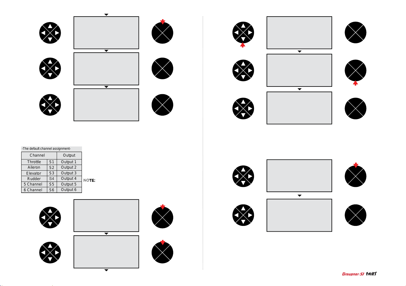
- Receiv out
Press the direction button to sel ect the receiv out line then press the ENT button to access the
funct ion. The c ursor is on the arr ow mark th en press the ENT button to access the functi on.
-The default channel assignment-
Channel
Throttle S1
Aileron
Elevator
Rudder
5 Channel
6 Channel
S2
S3
S4
S5
S6
Output
Output 1
Output 2
Output 3
Output 4
Output 5
Output 6
The default channel assignment appears on the screen.
Press the direction button to sel ect S1~S6 then press the ENT
and the di rection butto ns to highlight and change to th e desired
channel. Press t he ESC button to get back to the previous
screen.
NOTE: If you change S1 to S2, the S2 have the 2 channels of
output 1 a nd output 2 so the both servo of output 1 and output 2
are simultaneo usly moved w hen the stick of the S2 is move.
press
ENT
TEL VIW
ESC
ENT
TEL VIW
ESC
press
ENT
TEL VIW
ESC
- Rx bind
Press th e d i r ection b u tton to se l e ct rx bin d l ine then t h e c u rsor is at t h e hyphen. Turn on the receiver t hen pres s t h e E NT butto n o n the rece i v e r f o r o ve r 3 s econds s o that the re ceiver en t e r t h e
binding mode. Pre s s the ENT button of the transmi tter, the syste m will be co n nected w i t h in a few
secon d s a nd the mod e l n a me of the receiver is d i s p layed on the s creen after com p leting th e b i nd.
press
ENT
TEL VIW
ESC
ENT
TEL VIW
ESC
press
ENT
TEL VIW
ESC
- Range test
Press the direction button to sel ect the ra n ge test, the curso r is at the 99sec. Turn on the recei v er
then press the ENT button o n the transmitte r. With the ran ge test sta rted, the Graupner/SJ logo
blinks with beep for 99se c. Walk over 50 m e t ers away from the mod el with controll ing the tr a nsmitter sticks c onstantly and check whether the mo del is operating normally. You should have total
contr ol of the model with t he trainer switch p u lled.
29
Page 30
press
ENT
TEL VIW
ESC
ENT
TEL VIW
ESC
- RF transmit
RF transmit function allows to turn ON/OFF the RF power output.
Press the direction button to select the RF transmit then press the ENT button to select ON or OFF.
press
ENT
TEL VIW
ESC
ENT
TEL VIW
ESC
press
ENT
TEL VIW
ESC
press
ENT
TEL VIW
ESC
30
7. wing mix (AIRCRAFT)
Diff aile
The dif f aile mixing allows to overcome t he adver se yaw whe n the Aircraf t is deected. the ser vo
travel of t he aileron channel is so adjusted that the ight vertic al axis is straightened.
Diff aps
The dif f aps mixing allows the aileron channel to be mixed to the ap chan nel. If the ailer on is
operated, the ap is simultaneously operated. This mixing help to overcome adverse yaw charac-
teristics as well.
Aile->rudd
The aile ron to rud der mixing allows to ov ercome a dverse yaw charact eristi cs with the glider or the
scale Aircraft and ma ke s coordinating turns easier. When the a ileron c ommand is given, bot h o f
the aileron and the rudder are operated simultaneously.
Aile->aps
The aile ron to falp mixing allows enhance the per formance of the roll ight. W hen the aileron
command is given, both of the aileron and the ap are operated simultaneously.
Brak->elev
When the air brake of t he glider h as been programmed with th e v alue of the m o t or at C1 being n o
or no/inv, the air brake usually cause the ight nose up and down. The brake to elevator mixing
offer s the dow n and up signal to t he elevator to compensate for the ight nose up and down.
Brak->ap
When the air brake (with the value of the motor at C1 being no or no/ inv) is operated, both ap
servos is simul taneously moved fo r the landi ng approa ch. You can program the travel direction
and rang e of the ap ser vos.
Brak->aile
When the air brake (wi th the valu e o f the motor at C1 being no or no/inv) is operated, both aile ron
servos is simul taneously moved fo r the landi ng approa ch. You can program the travel direction
and rang e of the aile ron servos.
NOTE : The typic al programming for the air brake is that the aileron up, the ap down and the
elevator up.
Elev->ap
The elevator to ap mixing a llows the elevator channe l to be mixed to the ap channel. If the
elevator i s operated, the ap is simultaneously op erated. This mix ing help to enhance the ef fect of
the elevator in tight turns and aerobatics. The typical programming for elevator to ap is that the
elevator up and the ap down.
Elev->aile
The elevator to ap mixing a llows the elevator channe l to be mixed to the aileron channel. If the
elevator i s operated, the aileron is simultaneously operated. This mixi ng help to re inforce the
elevator r esponse . The typical programming is elevat or up to aile ron down an d elevator do wn to
aileron up.
Flap->elev
When the ap command is given, both of the ap, the ight nose up and down. The ap to elevator
mixing offers the down and up si gnal to the elevator to compensate for the ight nose up and
down.
Flap->aile
When the ap command is given, both of the ap and the aileron are operated simultan eously.
Diff-red
The different ial reduction mi xing allo w s the dif ferenti a l aileron mixing to w ork, even in the situation
that the airbra ke (the aileron up, th e ap dow n) is programmed so that you c an’t use the dif ferential aileron mixing.
Page 31
- Diff aile
Press th e E NT butto n t o a ccess t h e d i ff aile mixing th e n p r ess the EN T b u tton agai n t o h ighlight
the value . Press the d i r e ction bu tton to adj u s t t he desire d v a l u e then press the ESC button to
remove th e h i g h l ight. Pre s s the direction bu tton to sel ect the hyp h en then press the EN T b u tton.
The popu p messag e “ p ush desir e d s witch into positi o n on” appears. Move th e s w i t ch then th e
corr e s ponding va l ue appears (The d i ff aile mixing is on/off wh en the swit ch is moved). Pr e ss the
direct ion butt on to select other mi xing.
press
ENT
TEL VIW
ESC
press
ENT
TEL VIW
ESC
ENT
TEL VIW
ESC
press
ENT
TEL VIW
ESC
ENT
TEL VIW
ESC
press
- Diff ap
Press the direc tion button to select the dif f aps line and press the ENT b utton to highlight
the value . Press the d i r e ction bu tton to adj u s t t he desire d v a l u e then press the ESC button to
remove th e h i g h l ight. Pre s s the direction bu tton to sel ect the hyp h en then press the EN T b u tton.
The popu p messag e “ p ush desir e d s witch into positi o n on” appears. Move th e s w i t ch then th e
corresponding value appears (The diff aps mixing is on/off w hen the switch i s moved). Press the
direct ion butt on to select other mi xing.
press
ENT
TEL VIW
ESC
press
ENT
TEL VIW
ESC
press
ENT
TEL VIW
ESC
press
ENT
TEL VIW
ESC
ENT
TEL VIW
ESC
press
ENT
TEL VIW
ESC
press
ENT
TEL VIW
ESC
press
31
Page 32

press
ENT
TEL VIW
ESC
ENT
TEL VIW
ESC
ENT
TEL VIW
ESC
press
press
ENT
TEL VIW
ESC
ENT
TEL VIW
ESC
press
- Ail->rudd
Press th e d i r ection b u tton to se l e ct the ail - > rudd lin e a n d p r ess the EN T b u tton to hig hlight
the value . Press the d i r e ction bu tton to adj u s t t he desire d v a l u e then press the ESC button to
remove th e h i g h l ight. Pre s s the direction bu tton to sel ect the hyp h en then press the EN T b u tton.
The popu p messag e “ p ush desir e d s witch into positi o n on” appears. Move th e s w i t ch then th e
corr e s ponding va l ue appears (The a i l -> rudd mi xing is on /o ff when t h e s w i t ch is moved). Pr ess
the dire ction button to se l ect other mixing.
press
ENT
TEL VIW
ESC
ENT
TEL VIW
ESC
press
ENT
TEL VIW
ESC
press
32
ENT
TEL VIW
ESC
ENT
TEL VIW
ESC
- Ail->ap
Press th e direction but ton to select the ail -> aps line and press the ENT but ton to hig hlight the
value. Press the direction button to adjust the desired value then press the ESC button to remove
the highlight. Press the directi on button to select the hyphen then press the ENT button. The popup
messa ge “push desired sw itch into positio n on” appea rs. Move th e switch then the corresponding
value app ears (The ail -> aps mix ing is on /off when the switch is move d). Press the direc tion
butto n to select other mixing.
press
ENT
TEL VIW
ESC
ENT
TEL VIW
ESC
press
Page 33

press
ENT
TEL VIW
ESC
press
ENT
TEL VIW
ESC
press
ENT
TEL VIW
ESC
ENT
TEL VIW
ESC
ENT
TEL VIW
ESC
press
ENT
TEL VIW
ESC
ENT
TEL VIW
ESC
press
ENT
TEL VIW
ESC
press
ENT
TEL VIW
ESC
press
press
ENT
TEL VIW
ESC
- Brak->elev
Press th e d i r ection b u tton to se l e ct the bra k -> elev line a nd press t h e E N T b u tton to hi g h l ight
the value . Press the d i r e ction bu tton to adj u s t t he desire d v a l u e then press the ESC button to
remove th e h i g h l ight. Pre s s the direction bu tton to sel ect the hyp h en then press the EN T b u tton.
The popu p messag e “ p ush desir e d s witch into positi o n on” appears. Move th e s w i t ch then th e
corr e s ponding va l ue appears (The b r a k -> elev mix i ng is on/off when th e s witch is mo ve d) . P r e ss
the dire ction button to se l ect other mixing.
ENT
TEL VIW
ESC
ENT
TEL VIW
ESC
33
Page 34

- Brak->ap
Press the direc tion button to select the brak -> ap line and press the ENT button to highli ght
the value . Press the d i r e ction bu tton to adj u s t t he desire d v a l u e then press the ESC button to
remove th e h i g h l ight. Pre s s the direction bu tton to sel ect the hyp h en then press the EN T b u tton.
The popu p messag e “ p ush desir e d s witch into positi o n on” appears. Move th e s w i t ch then th e
corresponding value appears (The brak -> ap mixing is on /off when the switch is moved). Press
the dire ction button to se l ect other mixing.
press
ENT
TEL VIW
ESC
ENT
TEL VIW
ESC
press
ENT
TEL VIW
ESC
- Brak->aile
Press the direction button to sel ect the brak -> aile l ine and press the ENT button to highlight the
value. Press the direction button to adjust the desired value then press the ESC button to remove
the highlight. Press the directi on button to select the hyphen then press the ENT button. The popup
messa ge “push desired sw itch into positio n on” appea rs. Move th e switch then the corresponding
value appears (The brak -> aile mix ing is on/off when the switch is moved). Press the direction
butto n to select other mixing.
press
ENT
TEL VIW
ESC
34
press
ENT
TEL VIW
ESC
press
ENT
TEL VIW
ESC
press
ENT
TEL VIW
ESC
ENT
TEL VIW
ESC
ENT
TEL VIW
ESC
press
ENT
TEL VIW
ESC
press
ENT
TEL VIW
ESC
press
press
ENT
TEL VIW
ESC
Page 35

ENT
TEL VIW
ESC
press
ENT
TEL VIW
ESC
ENT
TEL VIW
ESC
- Elev-> ap
Press the direction button to select t he elec - > ap line and pre ss the ENT button to highlight the
value. Press the dir ection button to adjust th e d esired va l ue then press the ESC b u tton to re move
the high light. Press the di r ection button to select t he hyphen t h en press t he ENT but t on. The popup message “push d esired switch into position on” appe ars. Move t h e switch then the corresp ond-
ing value appear s (The elec -> ap mixing is on/off when the switch is move d). Press the direction
butto n t o select other mixing.
press
ENT
TEL VIW
ESC
ENT
TEL VIW
ESC
press
ENT
TEL VIW
ESC
press
ENT
TEL VIW
ESC
ENT
TEL VIW
ESC
- Elev->aile
Press th e d i r ection b u tton to se l e ct the ele c -> aile lin e a nd press t h e E N T button to highlig h t
the value . Press the d i r e ction bu tton to adj u s t t he desire d v a l u e then press the ESC button to
remove th e h i g h l ight. Pre s s the direction bu tton to sel ect the hyp h en then press the EN T b u tton.
The popu p messag e “ p ush desir e d s witch into positi o n on” appears. Move th e s w i t ch then th e
corr e s ponding va l ue appears (The e l ec -> aile mixing is o n/off wh e n t h e s witch is mo ve d) . P r e ss
the dire ction button to se l ect other mixing.
press
ENT
TEL VIW
ESC
press
ENT
TEL VIW
ESC
press
press
ENT
TEL VIW
ESC
ENT
TEL VIW
ESC
press
35
Page 36

press
ENT
TEL VIW
ESC
press
ENT
TEL VIW
ESC
ENT
TEL VIW
ESC
ENT
TEL VIW
ESC
press
ENT
TEL VIW
ESC
press
press
ENT
TEL VIW
ESC
ENT
TEL VIW
ESC
- Flap->elev
Press th e direction but ton to select the ap -> elev line and p ress the ENT button to highlight th e
value. Press the direction button to adjust the desired value then press the ESC button to remove
the highlight. Press the directi on button to select the hyphen then press the ENT button. The popu p
messa ge “push desired sw itch into positio n on” appea rs. Move th e switch then the corresponding
value app ears (The ap -> elev mixing is on/off whe n the switch is moved). Press the direction
butto n to select other mixing.
press
ENT
TEL VIW
ESC
ENT
TEL VIW
ESC
press
36
ENT
TEL VIW
ESC
ENT
TEL VIW
ESC
- Flap->aile
Press th e direction but ton to select the ap -> aile line and press the ENT but ton to highlight the
value. Press the direction button to adjust the desired value then press the ESC button to remove
the highlight. Press the directi on button to select the hyphen then press the ENT button. The popup
messa ge “push desired sw itch into positio n on” appea rs. Move th e switch then the corresponding
value app ears (The ap -> aile mix ing is on /off when the switch is move d). Press t he direc tion
butto n to select other mixing.
press
ENT
TEL VIW
ESC
Page 37

ENT
TEL VIW
ESC
ENT
TEL VIW
ESC
press
ENT
TEL VIW
ESC
press
ENT
TEL VIW
ESC
press
press
ENT
TEL VIW
ESC
ENT
TEL VIW
ESC
ENT
TEL VIW
ESC
- Diff-red
Press th e d i r ection b u tton to ac cess th e diff- r ed mixing then pre s s the ENT button to hig h l ight the
value. Pre ss the dire ction bu tton to adj u s t the desir ed value then press t h e E S C b u tton to rem o ve
the highlight.
press
ENT
TEL VIW
ESC
press
ENT
TEL VIW
ESC
press
ENT
TEL VIW
ESC
8. heli mix (Helicopter)
The mz-12 offers the mixing function in Helicopter model type. Heli mix is connected to 2 quick link
function and the mixes are assigned to each quick link function.
•
Ptch : The ptch mixing allows to adjust 5 points of the pitch curve that corresponds to the throttle
stick to maintain the best ight c onditi on. You can program the dif ferent pitch cur ve for each quick link.
•
Pitc-thro : pitc -> thro function allows to adjust 5 points of the throttle curve that corresponds to the
pitch angle for the throttle stick operation so that the engine or motor leads the best ight con dition. You
can program the different throttle curve for each quick link.
•
Pitc-rudd : It is pitch rudder mixing. This function is used for offsetting the counter torque that is
generated by the pitch of the main rotor or the change of the motor/engine RPM in accordance with the
movement of the throttle stick. You can set the point at the position where the counter torque is generated to program the rudder value. This mixing might not be necessary when the high performance
Gyro (Tail lock) or might be need to adjust the small value. You can adjust the different value for each
quick link.
•
Rudd-thro : This function is used to offset to fall down Helicopter engine RPM by the load that is
generated for rudd operation during Helicopter hovering. It can be offset with throttle channel.
•
Aile-thro : This function is used to offset to fall down Helicopter engine RPM by the load that is
generated for aile operation during Helicopter hovering. It can be offset with throttle channel.
•
Elev-thro : This function is used to offset to fall down Helicopter engine RPM by the load that is
generated for elec operation during Helicopter hovering. It can be offset with throttle channel.
•
Gyro : The gyro mixing allows to adjust the gyro gain. You can adjust the different gyro gain for
each quick link.
•
Swash lim : If the aileron and elevator related with the swashplat e is simultaneously controlled, the
linkage connected to the servo might be damaged. The swash lim mixing allows to restrict the travel
range of the swash plate to prevent the damage of the linkage. It is typically used for 3D Helicopter.
•
Governor 8ch : This function is used to set governor ON/OFF
•
Governor rate : This function is used to set the value of governor operation.
37
Page 38

- Ptch
Press EN T button t o acces s the ptch mixing then press t he ENT but ton again to access the function. -100% of the point 1 v alue is highlighte d. Move the throttle stick to the high position step by
step then the point 2,3,4,5 is selected in turn. After select ing the po int number, press the direction
butto n to adjust the desired value. Press the ESC button to re turn to th e previous screen.
NOTE : The default values of the point 2 and point 4 is remained not to be programmed so t he
“deact” is disp layed at the va lue box. You may act ivate and adjust the desired val ue by the direction
butto n if you want.
press
ENT
TEL VIW
ESC
press
ENT
TEL VIW
ESC
ENT
TEL VIW
ESC
ENT
TEL VIW
ESC
press
ENT
TEL VIW
ESC
38
press
press
press
ENT
TEL VIW
ESC
ENT
TEL VIW
ESC
ENT
TEL VIW
ESC
ENT
TEL VIW
ESC
ENT
TEL VIW
ESC
press
ENT
TEL VIW
ESC
press
ENT
TEL VIW
ESC
ENT
TEL VIW
ESC
Page 39
ENT
TEL VIW
ESC
ENT
TEL VIW
ESC
press
- Pitc->thro
Press the direction button to sel ect pitc->thro line and pr ess the EN T button to access the pitc>thro fu nction . 0% of the point 1 value is highligh ted. Move th e throttle stic k to the high position
step by step then the point 2,3, 4,5 is selected in tu rn. After selecting the point number, press the
direction button to adjust the des ired value . Press the E SC butto n to return to the previ ous scre en.
NOTE : The default values of the point 2 and point 4 is remained not to be programmed so t he
“deact” is disp layed at the va lue box. You may act ivate and adjust the desired val ue by the direction
butto n if you want. When the value of the point 2 and po int 4 are activated, the basic val ue of point 2
is 25% and point 4 is 75%
press
ENT
TEL VIW
ESC
ENT
TEL VIW
ESC
press
ENT
TEL VIW
ESC
ENT
TEL VIW
ESC
ENT
TEL VIW
ESC
press
ENT
TEL VIW
ESC
ENT
TEL VIW
ESC
press
ENT
TEL VIW
ESC
press
ENT
TEL VIW
ESC
press
ENT
TEL VIW
ESC
39
Page 40

ENT
TEL VIW
ESC
- Pitc->rudd
ruddPress the d irection button to select pitc->tail line and pre ss the ENT b utton to access the pitc ->
tail function . 0% of the point 1 value is highlighted. Move th e throttle stick to the high position step
by step then the point 2,3,4,5 is selected in turn. After select ing the po int number, press the direction button to adjust the de sired value. Press t he ESC butt on to retur n to the previous scr een.
NOTE : Th e d e f a u l t values of th e point 2 and p o i n t 4 i s r emained n o t t o b e p rogram m e d so the
“deact” is disp l ayed at the valu e box. You may activa te and adjust the desir ed value by th e d i r e ction button if you w a n t .
press
ENT
TEL VIW
ESC
ENT
TEL VIW
ESC
ENT
TEL VIW
ESC
press
ENT
TEL VIW
ESC
press
40
press
press
press
ENT
TEL VIW
ESC
ENT
TEL VIW
ESC
ENT
TEL VIW
ESC
ENT
TEL VIW
ESC
ENT
TEL VIW
ESC
press
ENT
TEL VIW
ESC
press
ENT
TEL VIW
ESC
ENT
TEL VIW
ESC
press
Page 41
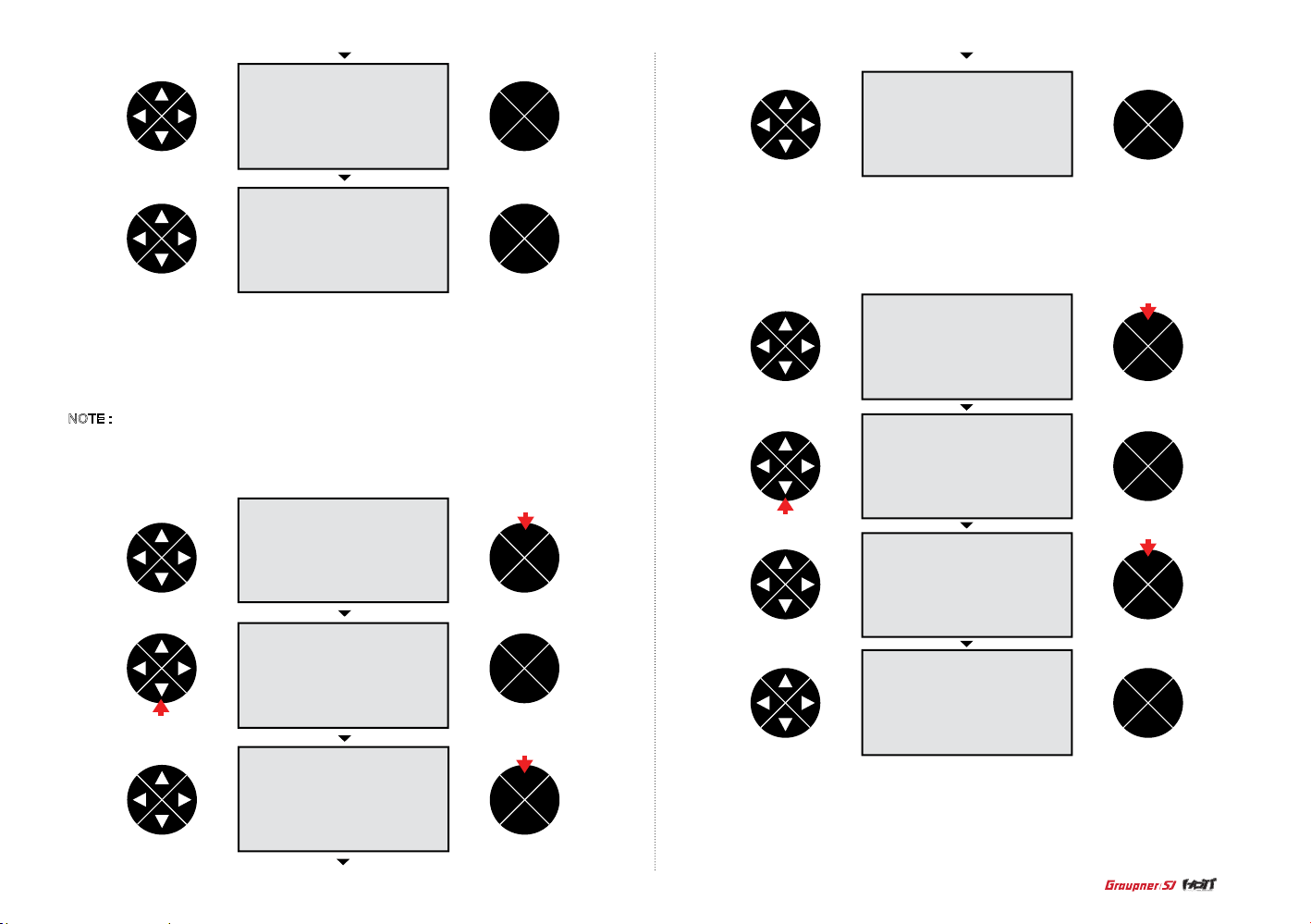
ENT
TEL VIW
ESC
ENT
TEL VIW
ESC
ENT
TEL VIW
ESC
- Rudd-thro
Press th e direction butt on to select rudd – th ro line and press the ENT button t o access the
rudd – th ro funct ion. The val ue 0% is high lighted then press the direc tion button to adjust the
desired value.
NOTE : In ca se that the directi on of Helicopter rotation is clockwise, rudd– thro function is
only ope rated when rudd is moved to the right side and if the direction of Helicopter rotat ion
is unclockwise, rudd–thro function is only operated when rudd is moved to the left side.
press
ENT
TEL VIW
ESC
ENT
TEL VIW
ESC
press
press
ENT
TEL VIW
ESC
- Aile-thro
Press th e d irecti o n button to s elect aile – thro lin e a nd press the ENT butt on to acce ss the
aile – thro functi on. The valu e 0 % is highlighted then press the d irecti on button t o a djust the
desired value.
press
ENT
TEL VIW
ESC
ENT
TEL VIW
ESC
press
press
ENT
TEL VIW
ESC
ENT
TEL VIW
ESC
- Elev-thro
Press the direction button to select elev – thro line and press the ENT button to access the
elev – thro function. The value 0% is highlighted then press the direction button to adjust the
desired value.
41
Page 42

press
ENT
TEL VIW
ESC
ENT
TEL VIW
ESC
press
ENT
TEL VIW
ESC
press
press
ENT
TEL VIW
ESC
ENT
TEL VIW
ESC
- Gyro
Press th e d i r e c tion but t o n t o s e l e ct the gyr o m i x i n g l i n e t h en press t h e ENT button t o
acces s the func t i on. 0% of the gy r o g a i n i s h ighlight e d. P r e ss the dire c tion but t o n t o a d ju s t
the desi r e d t h e g a i n t h en press t h e ES C b utton to remove the high l i g h t .
press
ENT
TEL VIW
ESC
ENT
TEL VIW
ESC
- Swash lim
Press th e d i r e c tion but t o n t o s e l e ct the swash l i m m i xing then p r e ss the ENT bu tton to
acces s the func t i o n . o ff of the swa s h l i m va l u e i s h i g h l i g h te d . Pr ess the dir e ction button to
adjust th e d e s i r e d the gain th e n p r e ss the ESC button to rem ove the highlight.
press
ENT
TEL VIW
ESC
ENT
TEL VIW
ESC
press
ENT
TEL VIW
ESC
42
press
ENT
TEL VIW
ESC
press
ENT
TEL VIW
ESC
press
Page 43
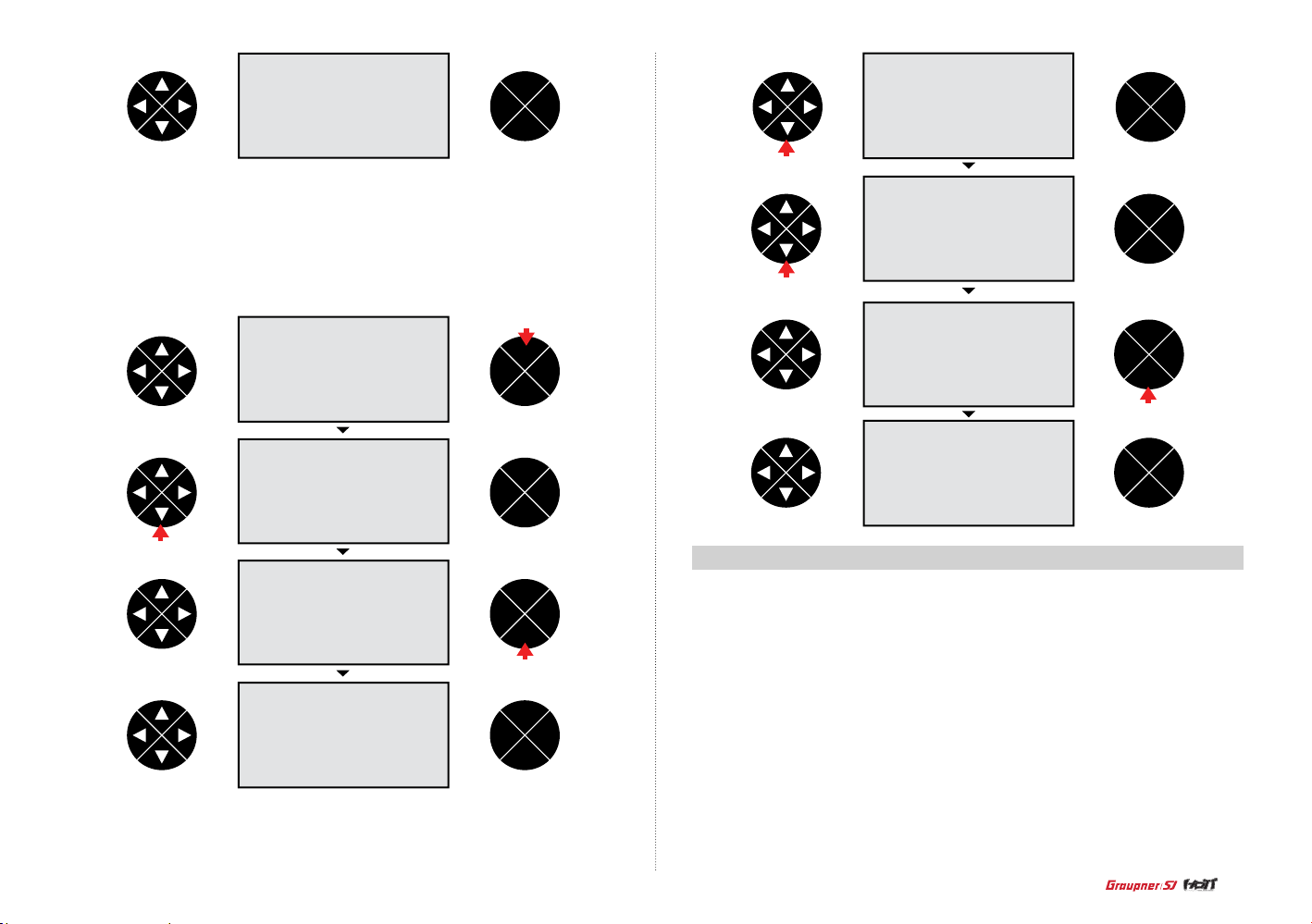
ENT
TEL VIW
ESC
ENT
TEL VIW
ESC
press
- Governor 8ch
Press th e d i r e c tion but t o n t o s e l e ct the governor 8ch then press the ENT bu tton to access
the func tion. The va l u e n o o f i s h i g h l i g h t e d. You may select yes or n o by t h e d i r e ction
button . Pr ess the ESC bu tton to rem ove the highl i g ht.
press
ENT
TEL VIW
ESC
ENT
TEL VIW
ESC
press
ENT
TEL VIW
ESC
press
ENT
TEL VIW
ESC
- Governor rate
Press th e d i r e c tion but t o n t o s e l e ct the governor rate t h e n p r e ss the ENT bu tton to access
the func tion. The va l u e 0 % o f i s h i g h l i g h te d . Pr ess the dir e ction bu tton to adju s t t h e d e
-
sired value then pre ss the ESC button to rem ove the highlight.
ENT
TEL VIW
ESC
press
ENT
TEL VIW
ESC
press
ENT
TEL VIW
ESC
9. free mixer (Aircraft and Helicopter)
The free mixer allows to select the master channel that is controlling channel and the salve channel.
The Master channel will be mixed to the slave channel and the slave channel will follow the master
channels input based on the rate that is programmed. Three free mixers are available for each of
the ten model memories.
- Free mixer
Press th e ENT but ton to access the free mixer. The rst ? ? at M1 line is highlighted then press the
ENT button to highlight the value. The rst ?? is for the master channel pr ogramm ing. Press the
direction button to sel ect the ma ster chan nel then p ress the ES C button t o remove the h ighligh t.
Press th e direction and ENT buttons to select the next M1 ?? and highlight the value. The next ?? is
for the slave channel programming. Press the direction button to select the slave channel then press
the ESC button to remove the hig hlight. Press the d irection button to select the hyph en then press
the ENT bu tton then the popup messa ge “push desired switch into position on” appe ars. Move the
switch then the corresponding value appears (The M1 free mixer is on/off when the switch is moved).
Press the direction button to sel ect the arrow mar k then press the ENT b utton to access the free
mixer ratio. The SYM is highli ghted then press the ENT button to highlight bot h v alues of the trv li ne.
Press the direction button to adjust the desired value. Both values are adjusted simultaneously and
appeared in the diagram.
43
Page 44

press
ENT
TEL VIW
ESC
ENT
TEL VIW
ESC
press
press
press
ENT
TEL VIW
ESC
ENT
TEL VIW
ESC
ENT
TEL VIW
ESC
press
ENT
TEL VIW
ESC
press
ENT
TEL VIW
ESC
press
ENT
TEL VIW
ESC
press
press
ENT
TEL VIW
ESC
ENT
TEL VIW
ESC
ENT
TEL VIW
ESC
press
press
ENT
TEL VIW
ESC
44
press
ENT
TEL VIW
ESC
press
ENT
TEL VIW
ESC
Page 45

press
ENT
TEL VIW
ESC
press
ENT
TEL VIW
ESC
ENT
TEL VIW
ESC
press
ENT
TEL VIW
ESC
press
press
ENT
TEL VIW
ESC
ENT
TEL VIW
ESC
- ASY
To adjust the different value for the master channel, press the direction button to highlight the ASY
from the SYM then press the ENT button to highlight the trv value in the right. Move the stick of the
master channel then you can select the trv value in the right side or left side. Press the direction
button to adjust the desired value. Both trv values are appeared in the diagram.
ENT
TEL VIW
ESC
press
ENT
TEL VIW
ESC
ENT
TEL VIW
ESC
press
ENT
TEL VIW
ESC
press
ENT
TEL VIW
ESC
press
ENT
TEL VIW
ESC
press
- STO
Press the direction button to sel ect the offset li ne then the STO is highlighted. Mo v e the stic k of the
mater ch annel till the vertical line on the diagram is moved to the desired positio n then press the
ENT but ton. The offset value is assigned at th at position.
45
Page 46

press
ENT
TEL VIW
ESC
ENT
TEL VIW
ESC
ENT
TEL VIW
ESC
- SEL
Press th e d i r ection b u tton to se l e ct the offset lin e t hen the STO is h i g h l ighted. Pr e ss the dire ction
butto n to select t h e SEL then p r e ss the ENT bu tton to hi g h l i g h t t he offs e t va l ue. Press t h e d i r ection button to adj u s t the desir ed value then press t h e ESC butto n t o r e m o ve t he highli g h t .
ENT
TEL VIW
ESC
press
1 time press
ENT
TEL VIW
ESC
ENT
TEL VIW
ESC
press
ENT
TEL VIW
ESC
press
46
10. Swash mix (Helicopter)
The Swas h m ix adjust s t h e a mount and d i r e ction of t r av e l f o r the aileron, elevat o r a nd pitch f u n ctions. You ca n a d j u s t t he high/low trave l r a nge of the swa shplate an d prevent fr o m t he mecha n ical inte rfere n ce of the lin k a g e .
Press th e d i r ection b u tton to hi g h l i ght the swqa s h p. m ix then pr e ss the ENT bu tton to ac cess the
funct i o n . The ptch, r o l l a n d n ick are avai l a b le. Press t h e d i r ection b u tton to se l e ct one of th e m
then pre ss the ENT and the dire ction bu ttons to hi g hlight an d a d j u s t t h e v a l u e . P r e ss the ESC
butto n to r emove the hi g h l ight.
press
ENT
TEL VIW
ESC
press
ENT
TEL VIW
ESC
ENT
TEL VIW
ESC
press
ENT
TEL VIW
ESC
press
Page 47

press
ENT
TEL VIW
ESC
ENT
TEL VIW
ESC
- Batt type
Press th e d i r ection b u tton to hi g h l i ght the bas i c s e tt then pr e ss the ENT bu tton to ac cess th e B a tt
type li n e . P r e ss the ENT bu tton to hi g h l i g h t the value then pres s t h e d i rectio n button to adjust th e
value. Pre ss the ESC button to re m ov e t h e h ighligh t . You may se lect the functi o n o f w hich you
wish to adjust the val u e by pressi n g t h e d i rectio n button.
press
ENT
TEL VIW
ESC
ENT
TEL VIW
ESC
11. Basic sett (Aircraft and Helicopter)
•
Batt type
The battery that is used to the transmitter can be selected. NiMH and LiPo are available.
•
Batt warning
When the transmitter voltage drops below the preset voltage, the transmitter beeps the alarm to warn
the low battery.
•
Touch sense
The touch sense is used for adjusting the sensitivity of the button. The available values are 1~10. The
lower the value, the more sensitive.
•
Contrast
Use the contrast to adjust contrast of the LCD. The available values are -20~20. The lower the value,
the more bright.
•
Display light
The backlighting time is adjusted.
•
Rf country
T6 offers 2 modes of GENERAL and FRANCE. You need the France RF setting to comply with France
regulations in FANCE. France RF setting should only be turned on when operating your transmitter in
France outdoors.
•
Voice volume
The volume of the telemetry is adjusted.
•
Beep volume
The beep volume is adjusted.
press
ENT
TEL VIW
ESC
ENT
TEL VIW
ESC
press
ENT
TEL VIW
ESC
press
ENT
TEL VIW
ESC
press
47
Page 48
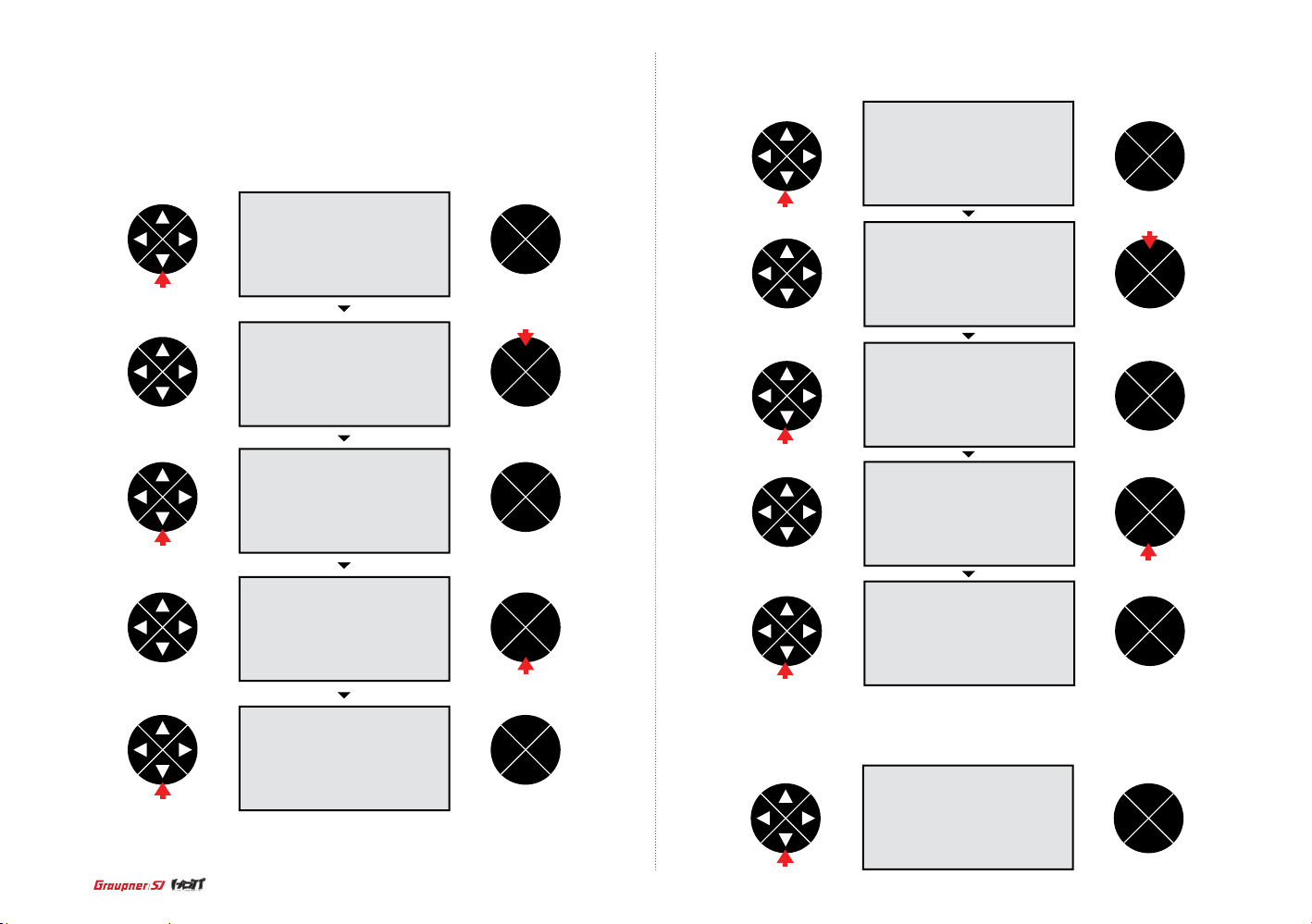
- Batt warning
Press the direction button to access the Batt warning line then press the ENT button to highlight the
value. Press the direction button to adjust the value. Press the ESC button to r emove the highlight.
- T ouch sense
The same method is used to access the function and adjust the value with Batt type programming.
ENT
TEL VIW
ESC
press
press
press
ENT
TEL VIW
ESC
press
ENT
TEL VIW
ESC
ENT
TEL VIW
ESC
ENT
TEL VIW
ESC
press
ENT
TEL VIW
ESC
press
press
ENT
TEL VIW
ESC
ENT
TEL VIW
ESC
press
ENT
TEL VIW
ESC
press
ENT
TEL VIW
ESC
press
- Contrast
The same method is used to access the function and adjust the value with Batt type programming.
ENT
TEL VIW
ESC
48
press
Page 49

press
ENT
TEL VIW
ESC
ENT
TEL VIW
ESC
press
ENT
TEL VIW
ESC
press
ENT
TEL VIW
ESC
press
ENT
TEL VIW
ESC
press
- Display light
The same method is used to access the functi on and adju s t the value w i th Batt type pro gramming.
ENT
TEL VIW
ESC
ENT
TEL VIW
ESC
press
ENT
TEL VIW
ESC
press
- RF country
The same method is used to access the function and adjust the value with Batt type programming.
ENT
TEL VIW
ESC
press
press
ENT
TEL VIW
ESC
press
press
ENT
TEL VIW
ESC
ENT
TEL VIW
ESC
press
49
Page 50

ENT
TEL VIW
ESC
press
ENT
TEL VIW
ESC
press
ENT
TEL VIW
ESC
press
- Voice volume
The same method is used to access the functio n and adjust the value wi th Batt type programming.
ENT
TEL VIW
ESC
press
press
ENT
TEL VIW
ESC
ENT
TEL VIW
ESC
press
- Beep volume
The same method is used to access the functio n and adjust the value wi th Batt type programming.
ENT
TEL VIW
ESC
press
press
ENT
TEL VIW
ESC
50
press
ENT
TEL VIW
ESC
ENT
TEL VIW
ESC
press
Page 51

ENT
TEL VIW
ESC
press
press
ENT
TEL VIW
ESC
ENT
TEL VIW
ESC
ENT
TEL VIW
ESC
12. Fail safe (AIRCRAFR and Helicopter)
When you b i n d y o u r t ransmitter, you are pr o g ramming t he recei ver with fa i l s a f e d e f a u l ts. If connecti o n is lost between th e t ransmitter and re ceiver, the re ceiver im mediate l y o p erates in t h ose
preprogrammed default positions. Grau pner/SJ r e ceiver ha s 2 failsaf e m odes, hold and Pos
(Position/Fail Safe)
- Hold
If you los e connec t ion bet ween the tr a n s m i tter and t h e r eceiver, all channel s h old the las t given
command.
- F/S
If the sig n a l is lost, all channels are dr i ve n t o their fai l safe pres e t p o sition du ring bin d i n g .
Press th e d i r ection b u tton to hi g h l i ght the fai l s a f e then press the ENT bu tton to ac cess the function. Th e black dot i s on the NO.1 channe l i n d icatin g NO.1 channel is selected a n d t h e Hold (the
default m ode) is assigned. Pres s t he direction button to sel e ct the cha n n el and press the ENT
butto n to select t h e F/S or the hol d. After complet i n g t o s elect th e d esired mode in all c h a n n e ls,
press t h e d i r e ction bu tton to select the Delay. Press t h e E N T b u tton to highlight t h e value then
press t h e d i r e ction bu tton to adj u s t the desir e d v a l u e . P r e ss the ESC button to hi g h l i ght the STO.
Move the st i ck to the de s i r e d positi o n then press the ENT bu tton. Th e p opup mes s a g e “posit i on
stored” appears (the F/S f unction is operated at that stick position). Conrm the fails afe setting is
corr e ct by turning off th e t ransmitter.
press
ENT
TEL VIW
ESC
ENT
TEL VIW
ESC
press
press
ENT
TEL VIW
ESC
ENT
TEL VIW
ESC
press
ENT
TEL VIW
ESC
press
51
Page 52

press
ENT
TEL VIW
ESC
ENT
TEL VIW
ESC
press
press
press
ENT
TEL VIW
ESC
ENT
TEL VIW
ESC
press
ENT
TEL VIW
ESC
press
ENT
TEL VIW
ESC
ENT
TEL VIW
ESC
ENT
TEL VIW
ESC
13. Trainer (Aircraft and Helicopter)
The mz-12 has the trainer functio n. The function activates w hen you sel ect Teacher, Pupil and
Normal mode. You may use t his func tion by wir eless an d wired.
- The teacher mode programming setup
Press the direction button to highlight th e teach pup il then press the EN T button to access the function. The black dot is on the NO.1 chan nel indicating N O.1 channel is selected and the T (Teacher /
the default mode) is assigned. Press the d irection button to select the cha nnel and press the ENT
butto n to select the T (Teacher) or –P (Pu pil). After comp leting to select the desired mode in al l
channels, press the direction b utton to select the hyphen. Press the ENT button then the popup
messa ge “push desired sw itch into positio n on” appea rs. Move th e switch that you wish to use as
the RF switch then the corresponding valu e appear s (The trainer fu nction is on/of f when that switch
is moved). Pr ess the direction butto n to select the n/a in the BIND. Th e transmitter gets ready to
bind to th e pupil transmit ter now.
press
ENT
TEL VIW
ESC
52
Page 53

press
ENT
TEL VIW
ESC
press
ENT
TEL VIW
ESC
press
press
ENT
TEL VIW
ESC
press
ENT
TEL VIW
ESC
ENT
TEL VIW
ESC
press
ENT
TEL VIW
ESC
ENT
TEL VIW
ESC
ENT
TEL VIW
ESC
- The pupil mode programming setup
After selecting the n/a in the BIND, press the ENT but ton then bind to the teacher tr ansmit ter. The
pupil transmitter doesn’t need to p rogram the other va lue.
When the teacher transmitter to the pupil transmitter has been bound, the teacher transmitter can control all channels and if RF trainer switch of the teacher transmitter would be moved to PUPIL position,
the pupil transmitter can control all channels
14. Info disp (AIRCAFT and Helicopter)
RFID and rmware version information are displayed. Press the direction button to highlight the info disp th en press the ENT button to acc ess the inf ormati on, you can check the
d
isplayed information.
press
ENT
TEL VIW
ESC
press
ENT
TEL VIW
ESC
ENT
TEL VIW
ESC
53
Page 54

15. Telemetry
16. SETTING & DATA VIEW
Telemetry is used to pe rfor m HoTT telemet ry prog ramming s e t u p a n d check H oTT te l e metry
data. 4 fu n ctions of SETTING & DATA VIEW, SENSOR SELECT, RF STATUS VIEW and VO I CE
TRIGG E R a r e av a i l a ble. Pres s T E L b u tton to go to the start up page o f telemetry. SETT ING
& DATA VIEW has been se l ected on t h e s tart up p a g e . W henever you r p r ess DOWN b u tton, 4
funct i o ns is selected in turn.
ENT
TEL VIW
ESC
press
ENT
TEL VIW
ESC
press
ENT
TEL VIW
ESC
press
ENT
TEL VIW
ESC
This fun ction is u s ed to program rece i v e r a n d t e lemetry senso r a n d g e t t he data inf o rmatio n o n
them. Th i s functi o n can be accesse d o n l y if transm i tter and r e ceiver ar e bound. If n ot, when th e
funct i o n is acce s s ed, the er r or messa g e “CAN’T RECIV E DATA OK” is appeared .
Press EN T b u tton to ac cess R X D ATA VIEW, you may p r ogram and get the dat a i n f ormati o n on
recei ve r d a ta. If tele m e try sen s or is conn e cted to receiver, you may al so progr a m a n d get the
data informati o n on teleme t ry sens o rs.
press
ENT
TEL VIW
ESC
ENT
TEL VIW
ESC
ENT
TEL VIW
ESC
16-1. RX DATA VIEW
54
press
ENT
TEL VIW
ESC
This function allows you to get the data information on receiver.
ENT
TEL VIW
ESC
Page 55
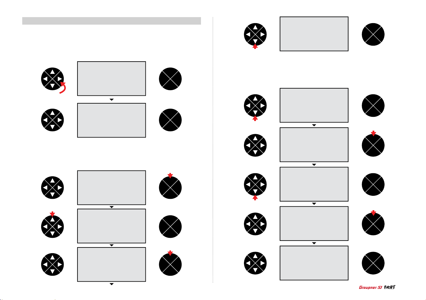
16-2. RX SERVO
This fun ction al lows you to pe rfor m s ervo pr ogrammi n g set up at the en tries of O UTPUT CH R E VERSE, CENTER , T RIM, LIMIT-, LIMIT+, PERIOD. Press the directio n button o n RX DATA VIEW
mode to access to RX SERVO t h en press D O WN butto n t o select t h e desired a rtic le. Press ENT
butto n to highlig h t the value on the sele cted ar t icle, you m ay change to t he desire d v a l ue.
ENT
TEL VIW
ESC
press
ENT
TEL VIW
ESC
- OUTPUT CH
The receiver output channel can be selected. Press ENT button to highlight the value and press UP/
DOWN buttons to set the desired value. Press ENT button to remove the highlight.
press
ENT
TEL VIW
ESC
press
ENT
TEL VIW
ESC
ENT
TEL VIW
ESC
press
- REVERSE
It is used t o d e cide the di rectio n o f s ervo rotation. P r ess DOWN b u tton to ac cess to REVERSE
line the n p r ess ENT button to highlight t h e d e f a u l t value OFF. Press UP/ DOWN button to sel e ct
ON or OFF. Press EN T b u tton to re m ov e t h e h ighligh t .
ENT
TEL VIW
ESC
press
press
ENT
TEL VIW
ESC
ENT
TEL VIW
ESC
press
press
ENT
TEL VIW
ESC
press
ENT
TEL VIW
ESC
ENT
TEL VIW
ESC
55
Page 56

- CENTER
The value o f s e rvo cen t e r i n t he selec t e d channel a t OUTPUT C H can be pro g rammed. T h e
center va l u e depends on transm i tter thr o ttle and trim pos i tion. Ge n e ral ser v o center val u e i s
1500us . P r ess DOWN b u tton to ac cess to CE N T E R l i ne then press ENT button to hi g h l i g h t the
default va l u e 15 00use c . Move and hold transm i tter thr o ttle at th e d esired p o s i tion the n p r ess ENT
butto n, the cente r v a l u e corre s p onding to t h r o ttle po s i tion is set .
press
ENT
TEL VIW
ESC
ENT
TEL VIW
ESC
press
press
ENT
TEL VIW
ESC
press
ENT
TEL VIW
ESC
ENT
TEL VIW
ESC
- TRIM
the servo trim can be set. P r e ss DOWN bu tton to ac cess to TR IM entr y t hen pres s E N T b u tton to
highli g h t t h e d e f a u l t v a l u e -000usec . P r ess UP/D OWN button to program the desired valu e a nd
then pre ss ENT but t on to remove the highli g h t .
ENT
TEL VIW
ESC
press
press
ENT
TEL VIW
ESC
ENT
TEL VIW
ESC
- LIMIT + / The max i m u m value for ea ch direction can b e progra m m ed so that th e m aximum s e rvo trave l l i m i t
of the co n n e cted servo is adju s t e d . T h e default val ue is 150% but t h e s e rvo trave l range is li m i t ed
to 100% tha t i s progra m m ed at SERVO EPA of transmit t e r s o the ser v o l i m i t i s not opera t e d a t
150% ~ 100%, b u t operate d a t b elow 100% . I f SERVO EPA of tran s m i tter is set t o 150 %, the LIMIT value c a n b e s e t b elow 150%. Press DOW N b u tton to ac cess to LI MIT+/- line then pr e ss ENT
butto n to h ighligh t t h e d e f a u l t v a l u e 15 0 %. Press U P/ DOWN but t on to program the des ired value
and then p r ess ENT button to remove the hig h l ight.
56
ENT
TEL VIW
ESC
press press
ENT
TEL VIW
ESC
Page 57
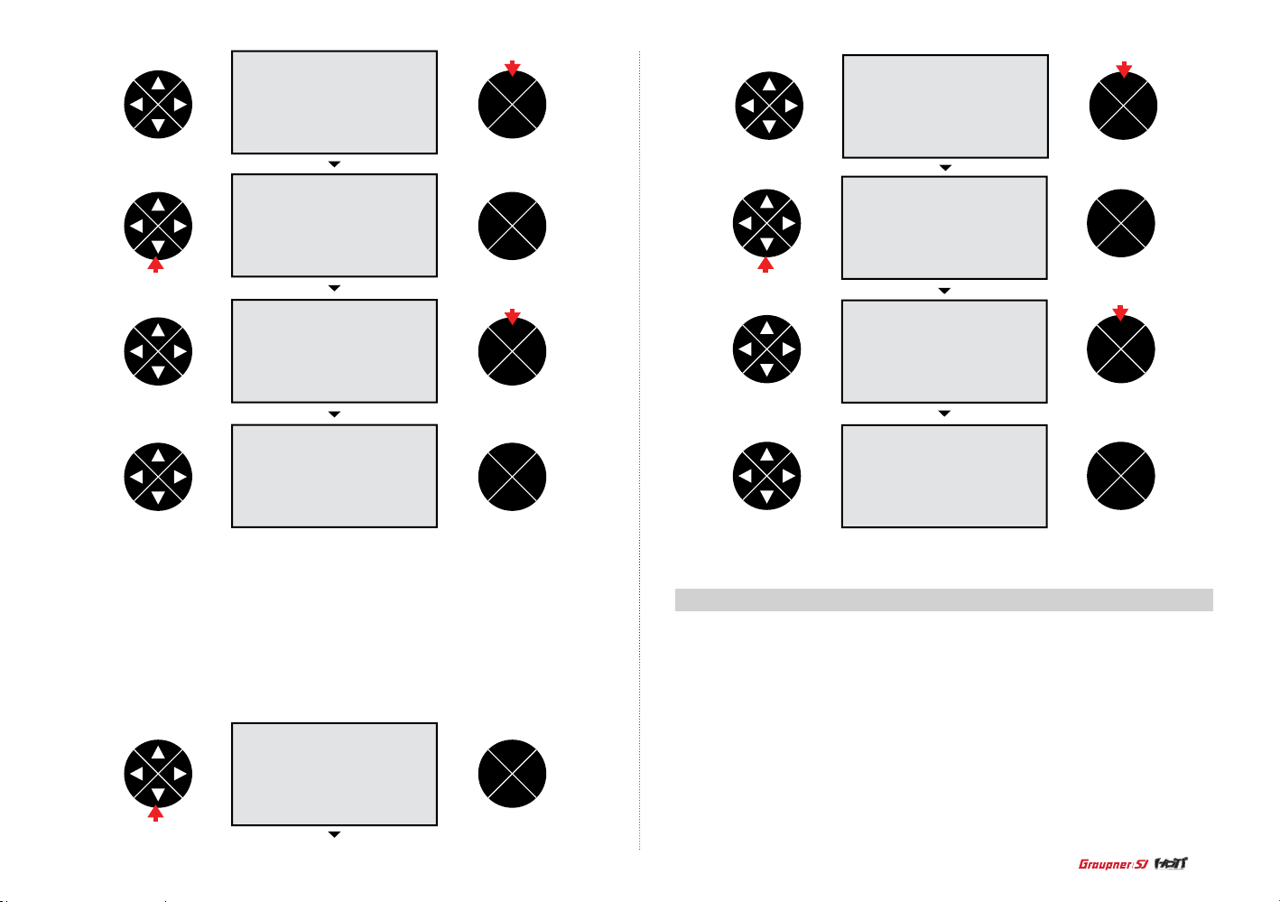
press
ENT
TEL VIW
ESC
press
ENT
TEL VIW
ESC
ENT
TEL VIW
ESC
press press
press
ENT
TEL VIW
ESC
ENT
TEL VIW
ESC
- PERIOD
The servo response time f or transm itter th r o ttle ca n be adjuste d . All chan n e l s that servo conn e cted are app l i ed separa t e l y. Pre ss DOWN bu tton to access to PERIOD lin e t hen pres s E N T b u tton
to highlight the default valu e 2 0msec. Press UP/DOWN button to set 10m sec or 20m sec and the n
press EN T button to remove the h i g hlight.
ENT
TEL VIW
ESC
press
ENT
TEL VIW
ESC
press
ENT
TEL VIW
ESC
ENT
TEL VIW
ESC
16-3. RX FAIL SAFE
OUTPUT CH (receiv er)/ INPU T CH (transm itter): It i s u sed to perform t he progr amming setup of
transm itter channel th at is bound t o r eceiver. The default se t up is that ea ch channel 1,2,3,4 ,5,6 of
recei ver is connected to t he same ch annel 1,2, 3,4,5,6 of transmitter. In case that R16, 16 chan nel
recei ver, is bound to mz-12, 6 cha n nel transmitte r, this funct ion is very useful. For example, 4 aile,
4 ap are used in aircraf t, 1~4 channels can be set to aile and 5~8 channels can b e set to ap and
then oth er channels can be s e t to elev or ru dd. Press t he direction button at EX SERVO mode to
go to RX FAIL SAFE mo de. OUTPU T CH line has b een selected at RX FAIL SAFE m ode. Pres s
ENT but t on to highlight the default valu e 1. Pr ess UP/DO WN button to select the desired channel
and then press ENT button to remove the h ighlight. Press D O WN butto n to access to INPU T CH
line. Pre ss ENT but t on to highl ight the default valu e 1. Press UP/DOWN butt on to select the de sired channel th at is conn ected INPUT CH and then press ENT but t on to remove t he highli ght.
57
Page 58
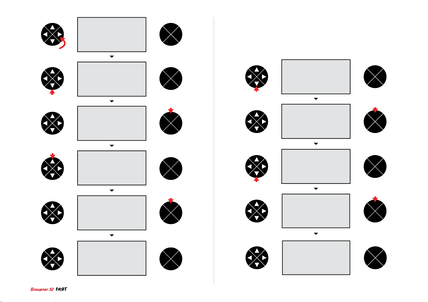
press
ENT
TEL VIW
ESC
- MODE
It is failsafe mode and HOLD/ FAIL SAFE/ HOLD are available.
Press DOWN button to access to MODE line then press ENT button to highlight the default value HOLD.
Press UP/DOWN button to select the desired value then press ENT button to remove the highlight.
press
press
ENT
TEL VIW
ESC
press
ENT
TEL VIW
ESC
ENT
TEL VIW
ESC
press
ENT
TEL VIW
ESC
ENT
TEL VIW
ESC
press
press
ENT
TEL VIW
ESC
ENT
TEL VIW
ESC
press
press
ENT
TEL VIW
ESC
58
ENT
TEL VIW
ESC
ENT
TEL VIW
ESC
Page 59
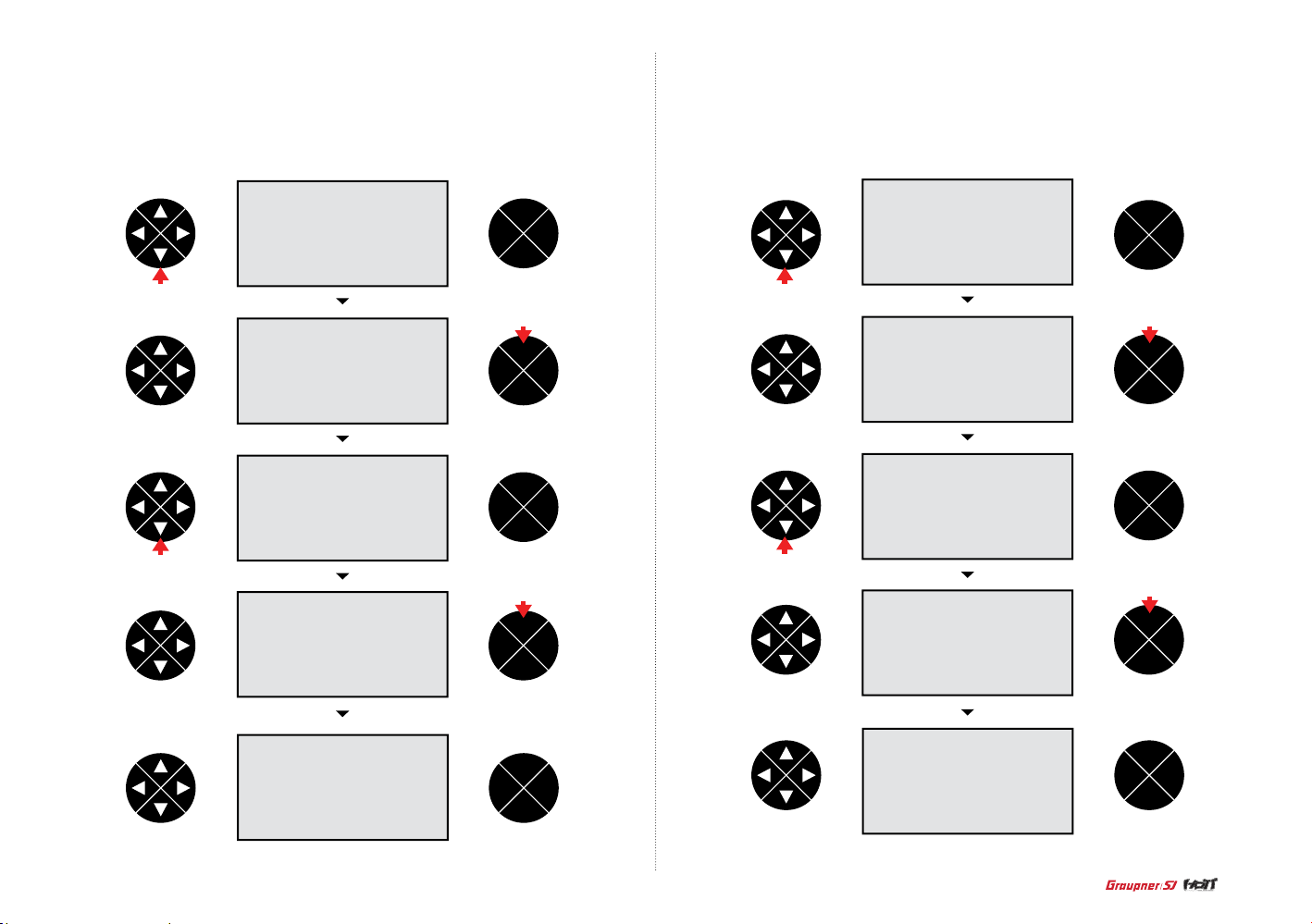
- F.S.POS.
It is used t o s et fail safe p o s ition at t h e d e s ired cha n n e l that you sel ect on OUTPUT CH.
Press DO WN butto n t o a ccess to F.S. Pos li n e then press ENT but t on to highl i g h t t h e default
value 150 0usec. Pr ess UP/D OWN butto n t o s elect th e d esired va l u e t h en press ENT butto n t o
remove the highlight.
- DELAY
This fun ction al l o w s y o u t o s e t t h e time that f a i lsafe take s t o s tart un d er failsa f e s i t u a tion
Press DO WN butto n t o a ccess to DELAY line th en press ENT butto n t o h i g hlight th e d e f a u l t va l ue
0.75sec. Pr ess UP/DO WN butto n t o s elect th e d esired val ue then press ENT button to remove
the highlight.
press
ENT
TEL VIW
ESC
press
ENT
TEL VIW
ESC
ENT
TEL VIW
ESC
press
ENT
TEL VIW
ESC
ENT
TEL VIW
ESC
presspress
press
ENT
TEL VIW
ESC
ENT
TEL VIW
ESC
press
press
ENT
TEL VIW
ESC
ENT
TEL VIW
ESC
ENT
TEL VIW
ESC
59
Page 60

- FAIL SAFE ALL
It is used when you change failsafe position value of all channels. You need set all channels to FAIL
SAFE to use this function.
Press DOWN button to access to FAIL SAFE ALL line then press ENT button to highlight the default
value NO. Move and hold transmitter throttle at the desired position then press ENT button, the failsafe value corresponding to throttle position is set. After setup FAIL SAFE ALL, if you need to check
whether the fail safe function is normal worked, turn off both of transmitter and receiver’s power
then servos should be operated to the preset failsafe.
ENT
TEL VIW
ESC
press
press
ENT
TEL VIW
ESC
ENT
TEL VIW
press
ENT
TEL VIW
ESC
16-4. RX FREE MIXER
This fun c t ion allow s y ou t o p e rfor m t h e FR E E M IXER pro g r a m m in g s e t up.
- MIXER
It is use to se l e ct the mixe r n um b e r t h a t yo u w an t to u s e
Press EN T b utton to hi gh l i g ht the defau lt v al u e 1 t h e n p r e s s UP/DOWN b u tton to sel e c t t h e
desire d c h a n n e l. P r e s s E N T bu tton to rem o ve t h e h i gh l i g ht. 5 mixers f r o m 1 t o 5 a r e ava i l ab l e .
press
ENT
TEL VIW
ESC
press
ENT
TEL VIW
ESC
press
ENT
TEL VIW
ESC
- POSITION
It indicates the o p erating r ange of thr o ttle at OUTPUT CH .
60
ENT
TEL VIW
ESC
ENT
TEL VIW
ESC
Page 61

- MASTER CH
Master C H i n FREE MIXE R can be sel e c t e d.
Press DO W N b u tton to ac c e s s t o MASTER CH l i n e t h e n p re ss ENT but t o n to h i g h l i g ht t h e
default va l u e 00. Press UP/DOWN b u tton to sel e ct the des ir e d channel then pre s s EN T b u tton to
remove the highlight.
- SLAVE CH
Slave CH in FR E E M I XER can be s e l e cted.
Press DO W N b u tton to ac c e s s t o S LAVE CH lin e t h e n p r e s s E N T bu tton to hi gh l i g ht t h e d e f au l t
value 00 . Pr e ss UP/DOW N b u tton to sel e ct the des i red chann e l t h en p r e ss ENT but t o n to
remove the highlight.
ENT
TEL VIW
ESC
press press
press
ENT
TEL VIW
ESC
press
ENT
TEL VIW
ESC
press
press
ENT
TEL VIW
ESC
ENT
TEL VIW
ESC
press
ENT
TEL VIW
ESC
ENT
TEL VIW
ESC
press
ENT
TEL VIW
ESC
ENT
TEL VIW
ESC
ENT
TEL VIW
ESC
61
Page 62
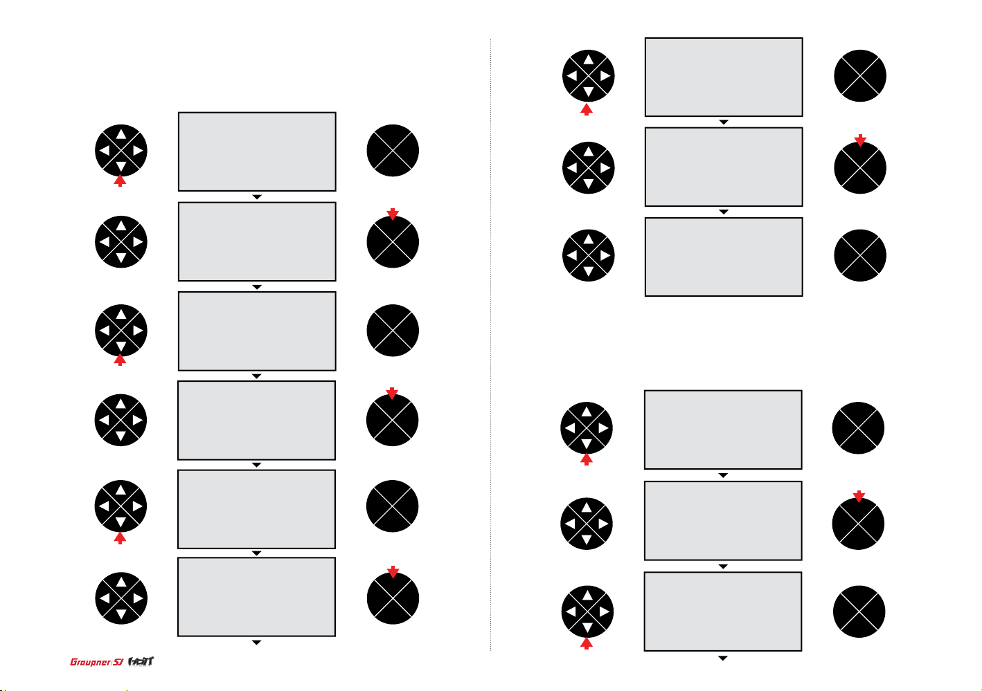
- S-TRAVEL + / The max i m um s e rvo trave l t h at i s connec t e d t o s la ve c h a n ne l can be pro g r a m m e d .
Press DO W N b u tton to ac c e s s t o S- TR AVE L+/- line the n p r e s s E N T b utton to hi g hl i g h t t h e
default va l u e 00. Press UP/DOWN b u tton to sel e ct the des ir e d channel then pre s s EN T b u tton to
remove the highlight.
ENT
TEL VIW
ESC
press
press
press
ENT
TEL VIW
ESC
press
ENT
TEL VIW
ESC
ENT
TEL VIW
ESC
press
ENT
TEL VIW
ESC
ENT
TEL VIW
ESC
press
ENT
TEL VIW
ESC
press
press
ENT
TEL VIW
ESC
ENT
TEL VIW
ESC
- RX WING MIXER TAIL TYPE
This fun c t ion is use d to s e t t h e p r o p e r t a i l type. You may sele ct one ty p e of Normal , V-Tail, Elevon can be s e l e c t e d d e p en d i n g o n t h e m o d e l type. Pre s s D O W N b u tton to ac c e ss to RX WING
MIXER TAIL TYPE li n e t h e n p r e s s E N T bu tton to hig h l i g ht t h e d e f au l t va l u e N O RMAL . P re ss
UP/DOW N b u t t o n t o s e l e c t t h e d e s i re d type th e n p ress ENT button to re m ove t h e h i g h li g h t .
ENT
TEL VIW
ESC
press
press
ENT
TEL VIW
ESC
ENT
TEL VIW
ESC
62
press
Page 63
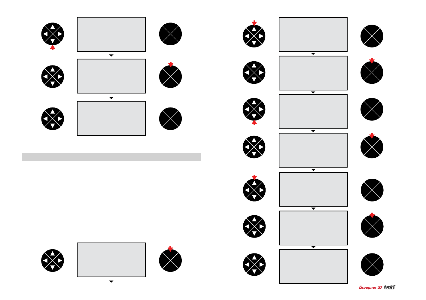
press
16-5. RX CURVE
ENT
TEL VIW
ESC
press
ENT
TEL VIW
ESC
ENT
TEL VIW
ESC
press
press
ENT
TEL VIW
ESC
press
ENT
TEL VIW
ESC
ENT
TEL VIW
ESC
press
ENT
TEL VIW
ESC
Perfo rm the expo n e n t i al p r ogrammi n g s e tu p a t RX CURV E m o d e . You may pr o g r a m t h e
exponen t i a l va l u e of channel 2 , 3 , 4. The defau lt s e tu p i s B c u rve that l e a ds S e rvo responds
propo rtion al l y d e p e n di n g o n t r a n s m itter thr o ttle movem e n t . A c u rve lead s t ha t S e rvo resp o n d s
sensit i ve l y an d C curve l e ad s t h a t S e rvo resp o n d s s oftly.
Press EN T b utton to ac cess to hi g hl i g h t t h e de f au l t c h a n n e l 2 0 o n C U R V E 1 C H l i n e t h en p r e ss
UP/DOW N b u t t o n s t o se l e ct the des i red chann e l. T h e d ef a u lt s e t up i s C H2 AILE, C H 3 E L EV,
CH4 RUD D. P re ss ENT but t o n to r e m ov e t h e hi g h l i g ht a n d p r e s s UP/DOWN b u tton to access
TYPE l i n e. P r e s s E N T bu tton to hig h l i g ht t h e d e f au l t va l u e B t h e n p re ss UP/DOWN butto n s to
selec t o n e of A, B, C. CUR V E2 and 2 can b e s e t i n t h e s a m e m et h o d w i t h C URVE1.
press
ENT
TEL VIW
ESC
press
ENT
TEL VIW
ESC
press
ENT
TEL VIW
ESC
ENT
TEL VIW
ESC
63
Page 64

16-6. RX SERVO TEST
It used to p e rform s e rvo test an d p r ogram th e vo l t a g e o f re ceiver po w e r, the max/mi n t e mperature of receiver CH OUT TY P E of r e ceiver. Pres s U P/ DOWN but t o n s to s e l e ct the des i re d l i n e
and pres s E N T b u t t o n t h e n t h e d ef a u l t va lu e i s h i g h l i g ht e d. P r e s s U P/ D O W N b u ttons to se t t h e
desire d va l u e a n d p re ss ENT but t o n to r e m ov e t h e hi g h l i g ht .
- ALL MAX
The max imum servo travel can be dec ided for servo tes t
- ALL Min
The mini m um servo travel ca n be decid ed for servo test
- TEST
You may start or stop servo test
press
ENT
TEL VIW
ESC
ENT
TEL VIW
ESC
press
press
ENT
TEL VIW
ESC
press
ENT
TEL VIW
ESC
press
ENT
TEL VIW
ESC
press
ENT
TEL VIW
ESC
ENT
TEL VIW
ESC
press
press
ENT
TEL VIW
ESC
ENT
TEL VIW
ESC
64
press
ENT
TEL VIW
ESC
press
press
ENT
TEL VIW
ESC
Page 65

press
press
ENT
TEL VIW
ESC
ENT
TEL VIW
ESC
press
ENT
TEL VIW
ESC
press
ENT
TEL VIW
ESC
press
ENT
TEL VIW
ESC
press
ENT
TEL VIW
ESC
ENT
TEL VIW
ESC
- ALARM VOLT : Low voltage warning
If rece i ve r vo l t a g e i s o u t of t h e p r e s e t vo l t a g e, t r a n s m i t t e r r e p e at s a b e e p w a r n i n g.
Press DO W N b u ttons to ac cess to A LARM VO LT and pr e s s E N T bu tton the n t h e d ef a u lt v a lu e
3.8V is hi g h lighted. Pr e s s U P/ DOWN but t o n s to s e t t h e d e s ir e d v al u e a n d p r e s s E N T b utton to
remove the highlight.
ENT
TEL VIW
ESC
press
ENT
TEL VIW
ESC
- ALARM TEMP + / - : Temperature warning
If receiver temperature is out of the preset temperature, transmitter repeats a beep warning.
Press DO W N b u ttons to ac cess to A LARM T E M P a n d p r e s s E N T b utton the n t h e d e fa u l t va l u e is
highli g ht e d. P r e s s U P/ D O W N b u ttons to se t t h e desired va lu e a n d p r e s s E N T b utton to re m ove
the highlight.
ENT
TEL VIW
ESC
press
65
Page 66

press
ENT
TEL VIW
ESC
press
ENT
TEL VIW
ESC
press
press
press
ENT
TEL VIW
ESC
press
ENT
TEL VIW
ESC
ENT
TEL VIW
ESC
press
ENT
TEL VIW
ESC
ENT
TEL VIW
ESC
ENT
TEL VIW
ESC
CH OUT TYPE
You may decide t h e si g n a l o u t p ut type of re ceiver. 5 typ e s o f O NCE / SAM E / S UMO12/ SUMI /
SUMD H D12 are ava i l a b le .
- ONCE
It is use fo r a na l o g u e s e rvo. If ON C E i s s e l e cted, PERI OD on RX S E R VO is s e t to 2 0msec aut omatically.
- SAME
It is use fo r di g i tal ser v o. I f S A ME is sele c t e d o n C H O U T TYPE li n e, y o u n e e d to s e t PE R I OD on
RX SER VO to 10 ~ 2 0 m s e c . w h e n a n a l o g u e se rvo is use d , 2 0mse shou l d b e s e t .
- SUMI
Receive r g e t t h e s i g na l o f t h e r e c e i ve r p e rfor m e d t h e S U MO progr a m m i ng s e t up then outp u t s t h e
signal
- SUMD HD
The digital output signal of all channels in re ceiver is outputted from the selected channel.
It is used t o the product that needs the receiver digital signal such as Power box and Flyba rless
system. The factory defau lt for SUMD HD outp ut channel is the last channel of receiver and you m ay
change it.
- SUMO
Only the selected chann el output s the signal of all cha nnels of re ceiver. In case that 1 receiver is
set to SUMO and the ot her rece iver is set to S UMI and th en they are c onnected in ex code , the
receiver set to SUMI outputs the signal c ame from the receiver set to SUM O. The nal channel of
recei ver is set to SU MO outpu t channel , b ut you may cha nge to the de sired ch a nnel.
Press DO WN butto n s t o a ccess C H OUTPUT TYPE an d p r ess ENT button the n t he default value
SAME i s h i g h l ighted. Pr e ss UP/DOW N button s t o s et the desir ed value and press EN T b u tton to
remove th e h i g h l ight. When you sele ct SUMO 12 and S UMD HD12 and try to sel e ct the different
output channel, press ENT button to move the highlight to 12 th en press UP/DOWN button to s elect
the desi red chan n el. Press E NT butto n t o remove the highligh t.
66
Page 67

press
press
press
ENT
TEL VIW
ESC
press
ENT
TEL VIW
ESC
ENT
TEL VIW
ESC
ENT
TEL VIW
ESC
ENT
TEL VIW
ESC
press
press
ENT
TEL VIW
ESC
ENT
TEL VIW
ESC
17. SENSOR SELECT
press
press
ENT
TEL VIW
ESC
ENT
TEL VIW
ESC
press
ENT
TEL VIW
ESC
It is used t o p r o g r am t e l e m et ry sens o r t h a t is connected to HoTT re c e i ve r. The s e n s o r s h o ul d b e
conne c t e d to t h e t e l e m et ry pin of re ceiver to u s e vo i c e functi o n , wa rning and t h e t e l e m et ry data
information.
Press DO W N b u ttons to go t o S E N S O R S E L EC T li n e a n d p r e s s E N T b utton to ac cess the f u n ction. Pr e s s D O W N b u tton to sel e c t o n e o f R EC E I V E R, GENERAL M O D ULE, ELECT R I C A IR.
MOD, VARI O M O DULE, GP S , ES C a n d p r e s s E N T bu tton to mark the box. T h e m a rked func t i o n
is activated.
ENT
TEL VIW
ESC
press
67
Page 68

press
ENT
TEL VIW
ESC
press
ENT
TEL VIW
ESC
ENT
TEL VIW
ESC
press
press
ENT
TEL VIW
ESC
ENT
TEL VIW
ESC
18. RF STATUS VIEW
It shows R F s t at u s b e tween tr an s m i tter and re ceiver th r o u g h te l e m e t ry func t i o n .
Press DO W N b u tton to go to R F S TATUS VIE W li n e a n d p r e s s E N T bu tton to ac cess to RF
STATUS VIEW mode. You may c h e c k R F s t a t us a t t h i s s c r e e n.
ENT
TEL VIW
ESC
19. VOICE TRIGGER
It is used t o p r o g r am the senso rs relate d w i t h vo i ce funct ion. The de f au l t a rticl e R E P EAT, TRIG,
VARIO, TRANSSMITT E R, RECEIV E R a r e ava i l ab l e a n d t h e o p t i o n a l se n s o rs could b e a ttache d .
If the opt i o n a l s e ns o r i s connec t e d, i t i s n e e d t o a d d t h e f u nction fo r t h e o p t i o n al s e n s o r a t S E NSOR SELEC T m o d e t h e n VO I C E T R I G GER art i cle is cre a te d . T h e u s ea b l e s e n s o r s a r e G E N E R AL MOD ULE, ELECT R I C A I R MODUL E , VAR I O MODUL E , G P S , A I R E SC .
- REPEAT
You may set the tim e an d s w i t c h a n d i f t h e sw i t c h i s o n , o n e of vo i ce func t i o n s is r e p e a te d f o r t h e
setti ng t i m e . Pr e s s DOWN but t o n s to g o t o VO I C E TRIGGE R l i ne a n d p r e s s E N T b u tton then the
default va l u e 10 s e c o n R E PEAT is highli gh ted. Press U P/ DOWN but t o n s to s e t t h e d e s ir e d v al u e
and pres s E N T b u t t o n t o r emove the hig h l i gh t . P ress the di re ction bu tton to hig h l i g ht t h e hy p h e n
mark th e n p re ss ENT but t o n. T h e p opup mes s a g e “ pu s h d e s i r e d sw i t c h i nt o p o s i t i o n o n” i s a ppeared . O p e r a te t h e s w i tch to be used a s R E P EAT on/off, th at s w i t c h i s d e s i gn a te d a s REPEAT
on/of f. A fter all pr ocess , R EP EAT functio n i s o perated w h e n t h e s w i tc h i s o n .
68
press
ENT
TEL VIW
ESC
ENT
TEL VIW
ESC
press
Page 69

press
ENT
TEL VIW
ESC
press
ENT
TEL VIW
ESC
ENT
TEL VIW
ESC
ENT
TEL VIW
ESC
- TRIG
You may designat e t h e s w i tc h f o r t h e v o i c e f u n c t i ons of tran s m i t t e r a n d r e c e i ve r a n d t h e vo i ce
funct i o n s ar e changed i n t u r n whenever t h e switch is o n /off. Pres s D OWN butto n s t o access t o
TRIG and p r e s s E N T b u tton then the popup m essage “ p u sh d e s i r e d s w i tc h i n to p o s i t i o n o n ” i s
appear ed. Oper a t e the switc h to be used as TRIG on/off, that switch is designated as TRIG on/off.
After a l l p r o cess, th e n ext voice f u n c t i o n i s a c cesse d w h en ev e r t h e sw i t c h i s o n .
If the swi tch that has s p ring suc h as S 2 i s d e s i g na t e d as TRIG swit c h , o n /o ff func t i o n i s o p e r a ted simultaneou s ly s o i t i s ve ry conve n i e nt .
press
press
press
ENT
TEL VIW
ESC
ENT
TEL VIW
ESC
press
ENT
TEL VIW
ESC
ENT
TEL VIW
ESC
ENT
TEL VIW
ESC
press
press
ENT
TEL VIW
ESC
ENT
TEL VIW
ESC
ENT
TEL VIW
ESC
69
Page 70

- VARIO
You may set the on/o ff switc h o f va r i o m odule for v o i c e f u n c t i on.
Press DO W N b u ttons to ac cess to VAR I O an d p r e ss ENT but t o n t h e n t h e p o p up m e ssage “p us h
desire d s w it c h i n to p o s i t i o n o n ” i s ap p e a r e d . O p e r a te t h e s w i tch to be used a s VAR IO on/of f, t h a t
switch i s d e s i gn a te d a s VA R I O o n /o ff. Voice fu nction is o p e r a t e d w h en the switc h i s o n .
- TRANSSMITTER
You may program the telem e t ry voice functi o n o f t r a n sm i tter, TX VOLT, BATTERY TIME, S TO PWATCH, RUNTIM E , P r e s s D O W N b u ttons to go t o T RANS MITTE R l in e a n d p r e s s E N T b u t t o n t o
acces s TRA N S M I TTER set u p m o d e. All voic e f u n c t i o n o f TX VOLT, BATTE RY TIME, STOP WATCH, RUNTIM E h av e b e en s e t to u s e. P r e s s t h e d i r e c t i o n b u tton to sel e c t t h e d e s i r e d l in e
and pres s E N T b u t t o n t o un m a rk the box if yo u d o n’ t w a nt t o us e v o i c e f u n c t ion for th e d e si r e d
line.
press
ENT
TEL VIW
ESC
press
ENT
TEL VIW
ESC
ENT
TEL VIW
ESC
ENT
TEL VIW
ESC
ENT
TEL VIW
ESC
press
press
ENT
TEL VIW
ESC
ENT
TEL VIW
ESC
press
press
ENT
TEL VIW
ESC
70
ENT
TEL VIW
ESC
Page 71

- RECEIVER
You may program the telem e t ry voice functi o n o f r e c e i ve r, TEMP, STRENGTH, R X VOLT, LOWVOLT, Press DOWN but tons to go to REC E I V E R l i ne a n d p r e s s E N T b u tton to access to RECEIVER setup mo d e. All voic e f u n c t i o n o f T E M P, STRENG T H , RX VOLT, LOWVOLT have been set to
use. Pres s t h e d i r e c t i o n b u tton to sel e c t t h e d e s i r e d l in e a n d p r e s s E N T b utton to unm a rk the box
if you don’ t wa nt t o u s e vo i ce funct i o n f o r t h e d e s i red line.
ENT
TEL VIW
ESC
press
press
ENT
TEL VIW
ESC
ENT
TEL VIW
ESC
press
press
ENT
TEL VIW
ESC
- If the opt i o n a l s e ns o rs are attached, the telem e t ry voice functi o n s o f an a ttache d optiona l
sensor s can be pro g r a m m e d . It i s n e e d t o a d d t h e f u nction fo r t h e o p t i o n a l se n s o r a t S E N S O R
SELECT mo d e t h e n VO I C E T R I G GER art i cle is cre a te d . B e l ow i s t h e ex a m p l e t ha t VO I C E TRIG GER ar t i c l e i s created.
ENT
TEL VIW
ESC
ENT
TEL VIW
ESC
ENT
TEL VIW
ESC
20. The Programming Setup For Telemetry Sensors
Press th e d i re ction bu tton on tr a n sm i tter hom e s c r e e n to go to rece i ve r t e le m e t ry scre e n.
Conne c t t h e o pt ional sen s o rs to rece i ve r t h e n p r e s s U P/ DOWN but t o n t o c h e c k a n d p r o g r a m t h e
desired optional sensors.
ENT
TEL VIW
ESC
ENT
TEL VIW
ESC
press
71
Page 72

press
ENT
TEL VIW
ESC
ENT
TEL VIW
ESC
press
press
press
press
ENT
TEL VIW
ESC
ENT
TEL VIW
ESC
ENT
TEL VIW
ESC
ENT
TEL VIW
ESC
ENT
TEL VIW
ESC
ENT
TEL VIW
ESC
press
ENT
TEL VIW
ESC
ENT
TEL VIW
ESC
press
ENT
TEL VIW
ESC
press
ENT
TEL VIW
ESC
72
Page 73

press
press
ENT
TEL VIW
ESC
ENT
TEL VIW
ESC
ENT
TEL VIW
ESC
•
Safety Approval
Declaration of Conformity
(in accordance with ISO/IEC 17050-1)
- Product(s): Graupner/SJ mz-12 Transmitter
Item Number(s):
Equipment class: 2
The objects of declaration described above are in conformity with the requirements of the
specications listed below, following the provisions of the European R&TTE directive 1999/5/
EC:
EN 62479:2010
EN 60950-1:2006/A11:2009/A1:2010/A12:2011
EN 301 489-1 V1.9.2
EN 301-489-17 V2.2.1
EN 300 328 V1.7.1
ENT
TEL VIW
ESC
FCC Information
- Graupner /SJ mz-12 Transmitter
Contains FCC ID: SNL-36204210
FCC 47 CFR PART 15C
FCC Statement
1. This device complies with Part 15 of the FCC Rules. Operation is subject to the following
two conditions:
(1) This device may not cause harmful interference.
(2) This device must accept any interference received, including interference that may cause
undesired operation.
2. Changes or modications not expressly approved by the party responsible for compliance
could void the user‘s authority to operate the equipment.
73
Page 74

NOTE
Caution
This equipment has been tested and found to comply with the limits for a Class B digital device, pursuant to Part 15 of the FCC Rules. These limits are designed to provide reasonable
protection against harmful interference in a residential installation. This equipment generates
uses and can radiate radio frequency energy and, if not installed and used in accordance with
the instructions, may cause harmful interference to radio communications. However, there
is no guarantee that interference will not occur in a particular installation. If this equipment
does cause harmful interference to radio or television reception, which can be determined by
turning the equipment off and on, the user is encouraged to try to correct the interference by
one or more of the following measures:
• Reorient or relocate the receiving antenna.
• Increase the separation between the equipment and receiver.
• Connect the equipment into an outlet on a circuit different from that to which the receiver is
connected.
• Consult the dealer or an experienced radio/TV technician for help.
FCC radiation exposure statement
This equipment complies with FCC radiation exposure limits set forth for an uncontrolled
environment. This equipment should be installed and operated with minimum distance of 20
cm between the radiator and your body.
KC Information
- Graupner /SJ mz-12 Transmitter
- KCC인증번호: KCC-RRM-sjr-16005100, KCC-CRM-sjr-36204210
- 방송통신위원회고시 제2013-01호 “무선설비규칙”
- 방송통신위원회고시 제2012-102호 “신고하지 아니하고 개설할 수 있는 무선기기”
• This equipment’s aerial must be at least 20 cm from any person when the system is in use. We
therefore do not recommend using the equipment at a closer range than 20cm.
• Ensure that no other transmitter is closer than 20cm from your equipment, in order to avoid
adverse effects on the system’s electrical characteristics and radiation pattern.
• The radio control system should not be operated until the Country setting has been set correctly
at the transmitter. This is essential in order to fulll the requirements of various directives -
FCC, ETSI, CE, KC and etc. Please refer to the instructions for your particular transmitter and
receiver for details of this procedure.
• Check all working systems and carry out at least one full range check on the ground before
every ight, in order to show up any errors in the system and the models programming.
• Never make any changes to the programming of the transmitter or receiver whilst operating a
model.
ENVIRONNEMENTAL PROTECTION NOTES
This product must not be disposed of with other waste. Instead,
it is the user’s responsibility to their waste equipment by handing it over to
a designated collection point for the recycling of waste electrical and
electronic equipment. The separate collection and recycling of
your waste equipment at the time of disposal will help to conserve natural resources and ensure
that it is recycled in a manner that protects human health and the environment. For more infor
mation about where you can drop off your waste equipment for recycling, please contact your
local city ofce, your household waste disposal service or wher
e you purchased the produce
-
-KN 301 489-1:2009
-KN 301 489-17:2009
-KN 61000-4-2:2008
-KN 61000-4-3:2011
74
Page 75
No. S1002
 Loading...