

Page 1

MZ-10 OPERATING INSTRUCTION
Prior to use, please read this manual thoroughly.
Keep this manual in a convenient place for quick and easy reference.
Page 2

Contents
•
BEFORE USE
•
Before Use
•
Support and Service
- Customer support
- Internet sales site
- A/S regulation
- Warranty regulation
•
Openhobby A/S Center
1. Box Contents
2. Safety Notes
3. Features
4. Specication
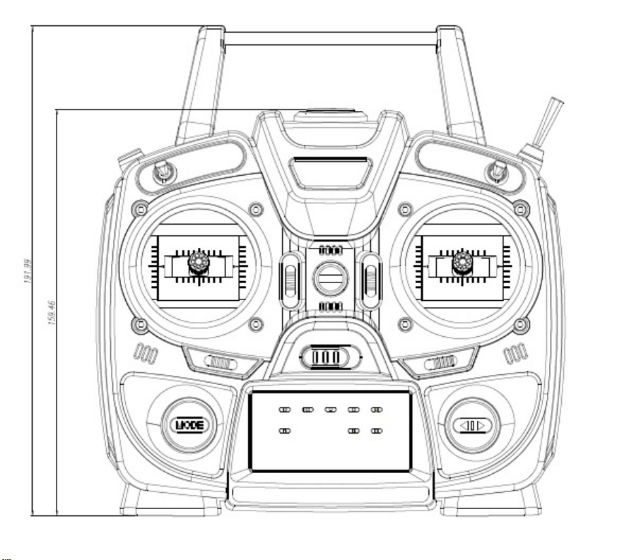
5. Transmitter Control Identication
6. Adjustble Stick Length
7. Adjustble Stick Testion
8. Mode exchange of throttle stick for Mode 1 and Mode 2
9. What is HoTT
•
Operation
1. Battery Installation
2. Charging Batteries
3. Turn on the transmitter
4. Binding
5. Servo Reversing
6. Dual Rate
7. Delta Wing
8. 2 AILE
9. V-Tail
10. FailSafe
11. RF Trainer
12. Country setting
13. Stick setting
14. Range testing
•
Error
•
Smart Box
•
Firmware Update
•
Safety Approval
2
2P
2P
2P
2P
2P
2P
2P
3P
3P
3P
3P
4P
5P
5P
5~6P
7P
7P
7P
7P
7P
7P
8P
8P
8P
8P
8~9P
9P
9~10P
10P
10~11P
11P
11P
11P
12P
12~13P
Thank you for purchasing mz-10 HoTT 2.4GHz Radio System. This system is extremely
versatile and may be used by beginners and pros alike. In order for you to make the best use
of your system and to fly safely, please read this manual carefully. If you have any difficulties
while using your system, please consult the manual, our online Frequently Asked Questions (on
the web pages referenced below), your hobby dealer, or t he Graup ner/S J S ervic e C enter. Du e
to unforeseen changes in production procedures, the information contained in this manual is
subject to change without notice.
•
SUPPORT AND SERVICE
•
Customer support
Please contact your Graupner/SJ importer in your region of the world or visit“www.openhobby.com” t o
assist you with any questions, problems or service needs.
•
Internet sales site
Please feel free to contact “www.openhobbby.com” to get all information on product features,
specications, running events and the newest product line up.
•
A/S regulation
Only when the product is faulty after normal operation within the warranty period, we will
repair the product for free based on our regulations. The repair will be paid for by the consumer when the damage is due to use in improper ways or beyond the warranty period.
Warranty regulation
Refer the WARRANTY CARD in a Package.
•
OPENHOBBY A/S CENTER
202 Dong- 201, Chunui Techno-Park II, 18, 198 street, Bucheon-ro, Wonmi-Gu,
Bucheon-Shi, Gyungki-Do KOREA 420-857
Phone: 82-70-7863-3672 Fax: 82-70-7863-3670
Customer Service E-mail: service@openhobby.com
1. BOX CONTENTS
mz-10 HoTT Transmitter
GR-12L 6 Channel Receiver
Manual
Shunt connecter
Charger
Waranty Card
Battery
Page 3
NOTICE
All instructions, warranties and other collateral documents are subject to change at the so le
discretion of Graupner/SJ. For up-to-date product literature, visit
http://www.openhobby.com and click on the support tab for this product.
WARNING
Read the ENTIRE instruction manual to become familiar with the features of the
product before operating. Failure to operate the product correctly can result in damage to the product, personal property and cause serious injury.
This is a sophisticated hobby product and NOT a toy. It must be operated with caution
and common sense and requires some basic mechanical ability. Failure to operate this product in
a safe and responsible manner could result in injury or damage to the product or other pr operty. This
product is not intended for use by children without direct adult supervision. Do not attempt disas-
sembly, use with incompatible components or augment product i n any way without t he ap proval
of Graupner/SJ. This manual contains instructions for safety, operation and maintenance. It is
essential to read and follow all the instructions and warnings in the manual, prior to assembly, setup
or use, in order to operate correctly and avoid damage or serious injury.
2. SAFETY NOTES
This is a sophisticated hobby product and NOT a toy. It must be operated with caution and common
sense and requires some basic mechanical ability. Failure to operate this product in a safe and
responsible manner could result in injury or damage to the product or other property. This product is
not intended for use by children without direct adult supervision. Do not attempt disassembly, use with
incompatible components or augment product in any way without the approval of Graupner/SJ. This
manual contains instructions for safety, operation and maintenance. It is essential to read and follow
all the instructions and warnings in the manual, prior to assembly, setup or use, in order to operate
correctly and avoid damage or serious injury.
1. Do not y your model near spectators, parking areas or any other area that could result in injury to
people or damage of property.
2. The radio system is affected by signal environment and the electronic jamming signals can cause
disorientation and loss of control of your aircraft.
3. Since models are hazardous when operated and maintained incorrectly, install and operate a radio
control system correctly and always pilot a model so the model is kept under control in all conditions
4. Ensure that all channels are working in the proper manner.
5. Do not y during adverse weather conditions. Poor visibility can cause disorientation and loss of
control of your aircraft. Strong winds can cause similar problems
6. When working with a model, always power on the transmitter rst and power off the transmitter last.
7. After a model is bound to a transmitter and the model is set up in the transmitter, always bind the
model to the transmitter again to establish failsafe settings.
8. When working with a model, always power on the transmitter rst and power off the transmitter
last.
9. Ensure all batteries are full charged before ying.
10. Only to use the recommended adapter when charging the battery of the transmitter and receiver
11.The transmitter shouldn’t be switched off at any time during ight
12. Perform a range check of the transmitter and the model before ying the model
13. Make sure all control surfaces correctly respond to transmitter controls before ying.
14. Perform the programming setup of the transmitter after removing a power battery from a model
or stopping an engine of a model.
15. Don’t move or touch the transmitter antenna during ight
3. FEATURES
1. 5 channels radio control set with Graupner/SJ HoTT 2.4 GHz technology(Hopping Intellective Telemetry)
2. The use of up to 75 channels ensures extreme operating reliability and immunity to external
interference.
3. Real-Time Telemetry analysis.
4. Displaying Telemetry data and programming receiver outputs with the optional Graupner/
SJ Smart-Box and the optional sensors.
5. Future-proof update capability using data interface.
6. Advanced HoTT wireless trainer system makes Teacher and Pupil system more enjoyable and
gives user convenience for the teaching/learning.
7. Simple, ultra-fast binding of transmitter and receiver.
8. Extremely fast re-binding, even at maximum range.
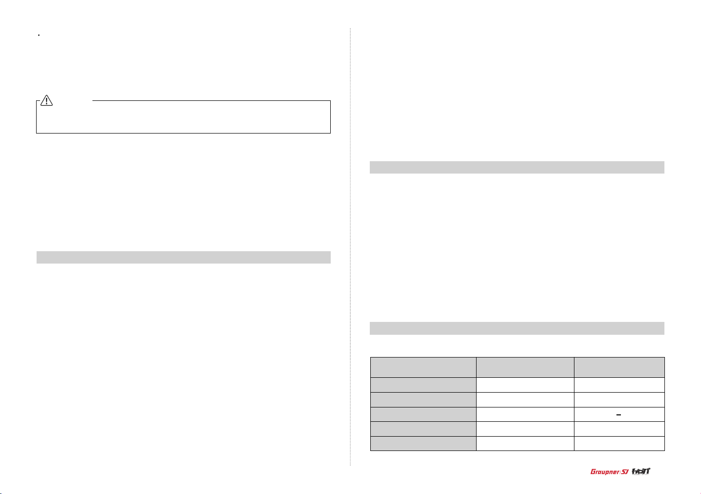
4. SPECIFICATION
Frequency band
Modulation
Output power
Current drain
Operating voltage
Transmitter mz-10
2.4~2.4835GHz
FHSS
100mW
Approx 125mA
3.4V~6V
Receiver GR-12L
2.4~2.4835GHz
FHSS
Approx 70mA
3.6V~8.4V
3
Page 4
Page 5
6. ADJUSTBLE STICK LENGTH
The control stick is consisted of 2pc of stick levers and it allows you to adjust the control stick’s
length as you want.
1. Hold the lever“B”and turn the lever“A”
counter clockwise The lock will be released.
2. Turn the lever“B”and adjust the control
stick’s length as you want. Turn the lever“A”
clockwise, then the lever“A”and“B”are
interlocked and fixed.
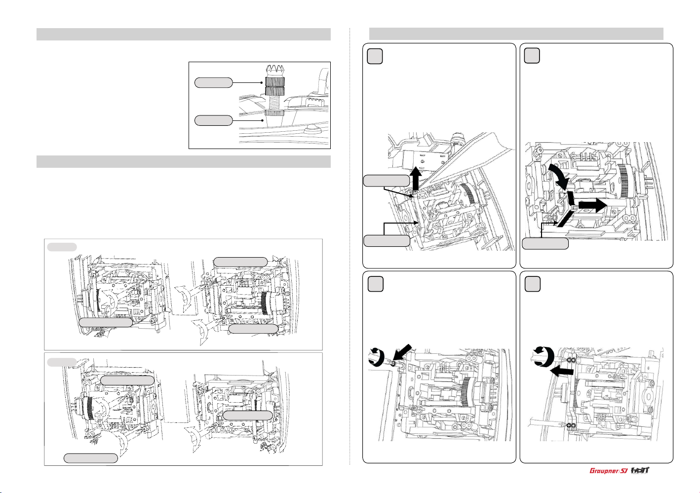
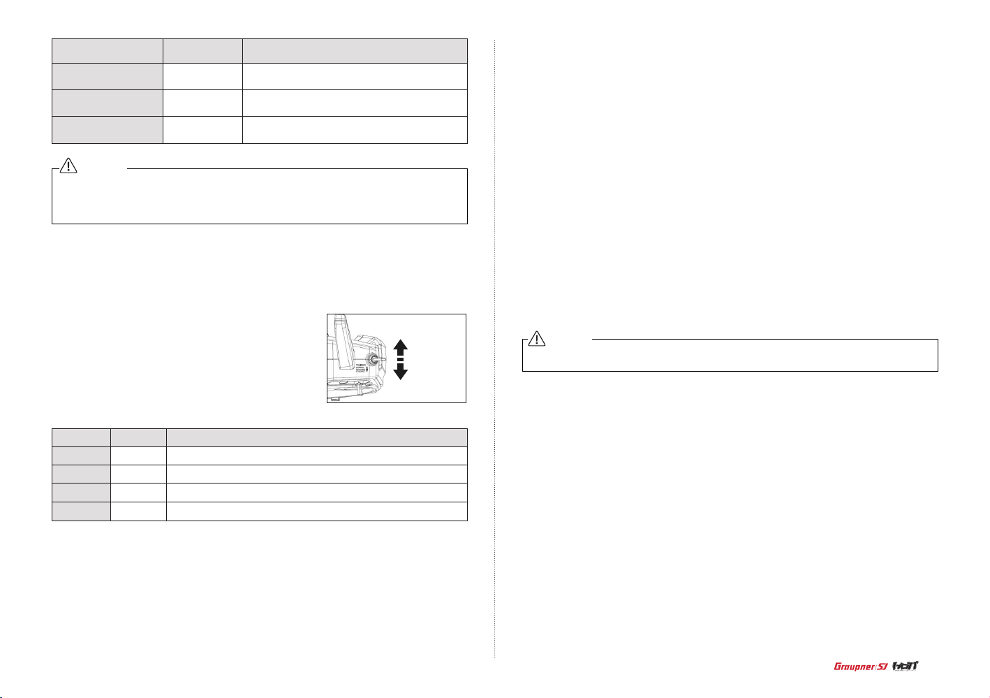
7. ADJUSTBLE STICK TENSION
The mz-10 offers adjustable tension on the throttle, aileron, elevator and rudder sticks.
1. Remove the battery cover and battery form the transmitter.
2. Unscrew the six Philips head screws that hold the transmitter’s rear cover and remove the rear
case.
3. Using a Philips screw driver, adjust the stick tension screw for the desired control. Clockwise to
tighten and counter clockwise to loosen.
Model 1
Lever“A”
Lever“B”
Elevator tension
8. Mode exchange of throttle stick for Mode 1 and Mode 2
1
Unscrew the transmitter’s rear case and
remove the rear case and disassemble the
tension spring from the centering cam in the
elevator gimbal of mode 1 transmitter with
tweezers
Tension spring
Centering cam
2
Centering cam
Disassemble the centering cam form
the gimbal
3
Unscrew the tension spring control bolt in
the elevator gimbal of mode 1 transmitter
4
Disassemble 2pcs of leaf spring in the
throttle gimbal of mode 1 transmitter
Aileron tension
Model 2
Aileron tension
Elevator tension
Rudder tension
Rudder tension
5
Page 6

5 9
Unscrew the tension spring control bolt in
the elevator gimbal of mode 1 transmitter
6 10
Screw the disassembled bolt from the
throttle gimbal of mode 1 transmitter into the
elevator gimbal to x the controller
Assemble the centering cam into the
throttle gimbal of mode 1 transmitter and set
the spring in the center control part and the
centering cam with tweezers
Screw the disassembled tension control bolt from the elevator gimbal of mode
1 transmitter into the throttle gimbal and
adjust the bolt for the desired control
7
Assemble 2pcs of disassembled leaf
spring from the throttle gimbal of mode 1
transmitter into the elevator gimbal and adjust
the bolt for the desired control
6
8
Assemble the disassembled centering
cam form the elevator gimbal of mode 1 trans
mitter into the throttle gimbal pin
-
Assemble the transmitter’s rear case and switch to mode 2 from mode 1 at Stick mode page in
the transmitter programming setup section according to the manual.
Tension spring
NOTICE
Make sure to test all functions are normally operated in mode 2 before ying
Page 7

9. WHAT IS HoTT
HoTT stands for Hopping Sequence Telemetric
Technology, it is Graupner/SJ’s unique telemetry
technology in 2.4GHz signal protocol that supports
Bi directional data transmission gives user real-time
informat ion on things like us er model’s
RP M, Volt age, Temperature, User programmed
warning, and etc. The use of up to 75 c hannels
ensures extreme operating reliability and immu -
nity to external interference thanks to optimized
frequency hopping broad channel sequence.
- OPERATION
All Graupner/SJ charge jacks are cent er-pin negative. This is the opposite of many chargers.
Before us ing a charger make sure the connector is center-pin negati ve. This can be done using a
voltmeter. Also unlike conventional radio systems that use 8 cells to power the transmitter, the mz-10
charger designed for a 4-cell 4.8-volt battery pack when charging the transmitter.
3. Turn on the transmitter
Leave the trainer switch to Normal position and turn on the transmitter.
Normal
Teacher
Pupil
1. Battery Installation
Optional NiCd or NiMH 1.2-volt AA rechargeable 4-cell batteries can be used. A battery connecter
is on the inside of the transmitter for convenient recharging. Graupner/SJ offers rechargeable
NiCd, NiMH batteries, part number S22331.
Remove the battery cover and install the battery pack ensuring
the polarity of the battery connecter.
2. Charging Batteries
The included charger is designed to recharge your batteries at a rate of 150mA. Do not use this
charger for equipment ot her than Graupner/SJ t ransmitters that use 4-cell battery packs. The
charging plug polarity may not be the same and equipment damage can result. During the charging
operation, the charge
DC port won’t transmit during charging.
CAUTION
Charge only rechargeable batteries. Non-rechargeable
batteries may burst causing injury to persons and/or damage
to propert y. Never leave charging batteries unattended
r’s temperature is slightly elevated. This is normal.
Transmitter Charge Jack Polarity
Graupner/SJ
The mz-10 is compatible with all current Graupner/SJ aircraft receivers (R Series)
4. Binding
You must bind the receiver to the transmitter before the receiver will operate . Binding teaches the
1. Switch on the transmitter and receiver.
2. Press & hold the SET button on the receiver for over 3 sec until the receiver enters BIND mode.
3.
Press the MODE button on the transmitter, the system will be connected within a few seconds.
Once connected, the bind LED on the transmitter will turn solid orange and the status LED on the
receiver will turn solid green, indicating the receiv er is bound to the t ransmitter. If the binding
process has failed, repeat the whole procedure.
LED before binding
Transmitter
Receiver
Orange LED Off Orange LED On
Green LED Off Green LED On
ly connect to it’s corresponding transmitter.
LED after Binding
7
Page 8
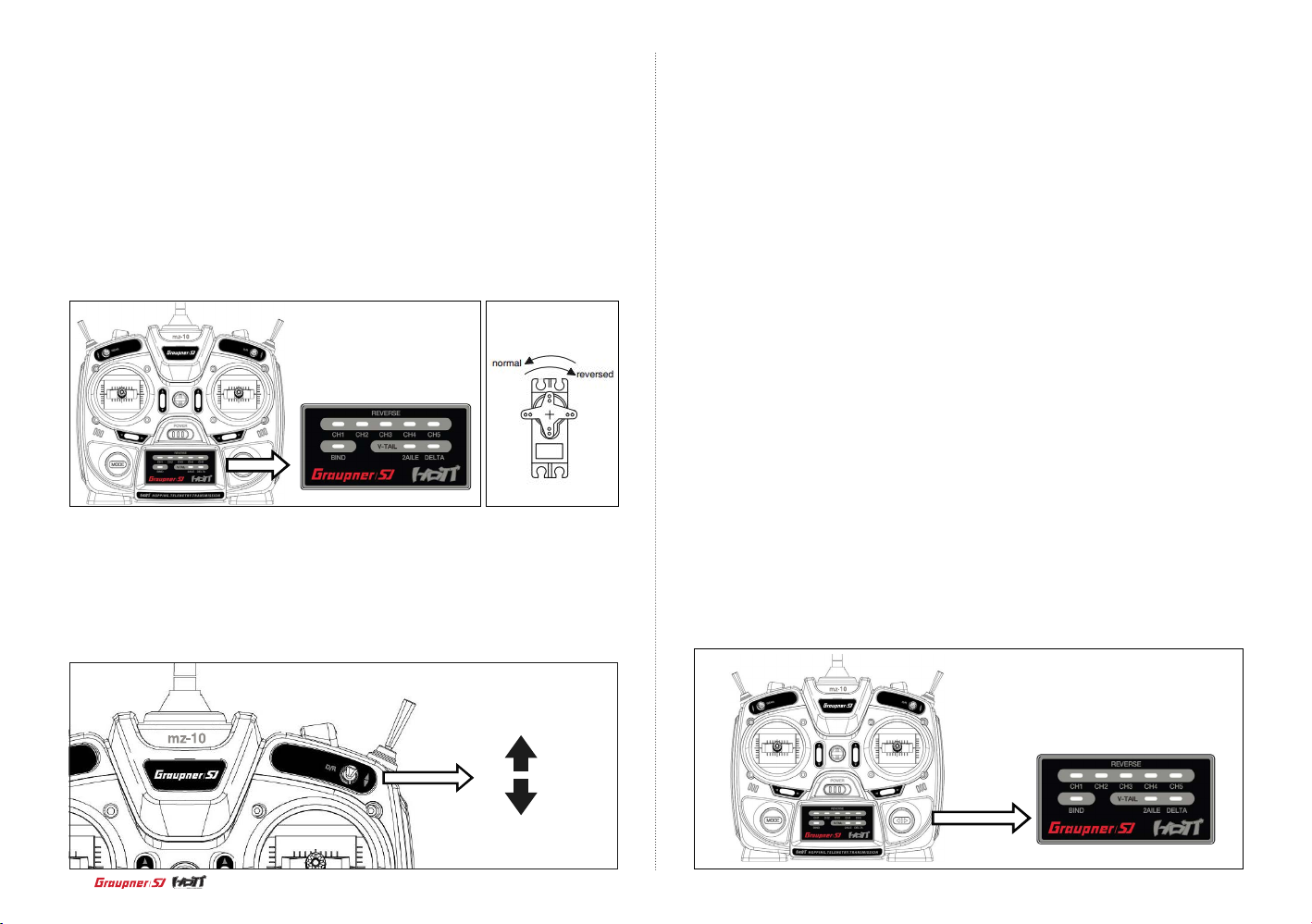
5. Servo Reversing
According to the LED status of each channel, you may check that the direction of servo rotation is in
the normal or reverse, LED blinking means that direction of servo rotation is in the normal and LED
turning on means that the direction of servo rotation is in the reverse.
1. Press & hold the DIRECTION button for over 2 sec and then release the button, the transmit-
ter enters reverse mode and the LED of No. 1 channel blinks.
2. Press the MODE button, the LED of No. 1 channel goes solid and the direction of servo rotation is
in the reverse.
3. Whenever you press the DIRECTION button, you may select the channel that you want and may
set the direction of servo rotation in the same method above.
4. After setting servo reversing function, press & hold the DIRECTION button for over 2 sec and then
release the button, now all servo reverse setting is stored to the transmitter.
6. Dual Rate
The mz-10 offers a dual rare function on aileron, elevator and rudder. When the DUAL RATE
SWITCH is in the up position, 100% travel is achieved on the aileron, elevator and rudder chan-
nels. W hen the switch is in the down position a reduced travel of 70% is achieved on the aileron,
elevator and rudder channels. This is useful allowing the aircraft to have a high control rate (switch
in the up position) for aggressive maneuvers and a low control rate (switch in down position) for
smooth, precise maneuvers.
7. Delta Wing
The mz-10 offers a delta wing mix. delta wing mixing combines the function of ailerons with the
function of the elevator to allow precise control of both roll and pitch for delta wing aircraft.
1. Press & hold the DIRECTION button for over 2 sec and then release the button, the transmit-
ter enters Reverse mode.
2. Press the DIRECTION button repeatedly until the delta LED is on, then the transmitter enters
delta mode. If delta mode is not set previously, the LED would blink.
3. Press the MODE button, the LED goes solid and delta wing function is activated.
4. After setting delta wing function, press & hold the DIRECTION button for over 2 sec and then release
the button, the delta LED turns solid green, the delta wing setting is stored to the transmitter.
8. 2 AILE
2 ailerons function is designed to allow more precise control. you may use 2 separate channels to
control the left and right aileron
1. Press & hold the DIRECTION button for over 2 sec and then release the button to enter reverse mode.
2. Press the DIRECTION button repeatedly until the 2 aile LED is on, then the transmitter enters 2
aile mode. If 2 aile mode is not set previously, the LED would ash.
3. Press the MODE button, the LED goes solid and 2 aile function is activated.
4. After setting 2 aile function, press & hold the DIRECTION button for over 2 sec and then release the
button, 2 aile LED turns solid green and 2 aile setting is stored to the transmitter.
9. V-Tail
If the model features a V-tail instead of a conventional tail, you need to set V-tail.
1. Press & hold the DIRECTION button for over 2 sec and then release the button, the transmit-
ter enters reverse mode.
2. After setting of delta and 2 aile according to above described procedure, press & hold the DIRECTION
button for over 2 sec and then release the button. Delta LED and 2 aile LED go solid green together
and V-tail function is activated. Delta LED and 2 aile LED are off after 5 seconds.
100%
70%
8
Page 9
Function setting LED Description
DE LTA
2 AILE
DELTA and 2 AILE
Green LED On
Green LED On
2 Green LED On
Delta wing function is activated,
2 Aile and V-tail functions are de-activated.
2 Aile function is activated,
Delta and V-tail functions are de-activated.
V-tail function is activated,
Delta and 2 aile functions are de-activated.
NOTICE
You may select only 1 function of delta, 2 aile and V-tail
When mz-10 is switched on, the status LED of each function that you set is turned on for 5
seconds to indicate which function has been set.
10. FailSafe
When you bind your transmitter, you are programming the receiver with failsafe defaults. Graupner/SJ
receiver has 4 Failsafe modes: FAILSAFE, HOLD, OFF and STANDARD.
1-1. Switch on the receiver and place transmitter RF
TRA IN ER SWITCH at normal position. Press and hold the
MODE button and switch on the transmitter. The Graupner/SJ
logo repeat to blink a single red with a single beep, indicating
that you entered the failsafe mode. Every time you press MODE
button at failsafe mode, the 4 modes are changed in turns.
Normal
Teacher
Pupil
- HOLD
Enter hold mode by pressing MODE button once from the failsafe mode. The Graupner/SJ logo
repeats to blink twice red with twice beep. Press & hold the MODE button for over 2 sec and release
the button. The Graupner/SJ logo turns solid red, indicating the hold mode has been set. If you lose
connection, all channels hold the last given command.
- OFF
Enter off mode by pressing MODE button once from the hold mode. The Graupner/SJ logo repeats
to blink 3 times red with 3 times beep. Press & hold the MODE button for over 2 sec and release
the button. The Graupner/SJ logo turns solid red, indicating the off mode has been set. Even if you
lose connection, the failsafe is not working.
- STANDARD
Enter standard mode by pressing MODE button once from the hold mode. The Graupner/SJ logo
repeats to blink 4 times red with 4 times beep. Press & hold the MODE button for over 2 sec and
release the button. The Graupner/SJ logo turns solid red, indicating the standard mode has been
set. standard features that the throttle channel ( channel Number 1 ) is move into low throttle
position and other channels hold last given command.
NOTICE
Failsafe setting could be only set in case that RF TRAINER SWITCH
is at normal ight position
Button
Once
Once more
Once more
Mode
FAILSAFE
HOLD
OFF
STANDARD
Repeating that the Graupner/SJ logo blinks a single red with a single beep
Repeating that the Graupner/SJ logo blinks twice red with twice beeps
Repeating that the Graupner/SJ logo blinks three times red with three times beeps
Repeating that the Graupner/SJ logo blinks four times red with four times beeps
LED status and beep
1-2. Failsafe mode
- FAILSAFE
Move the control sticks on the transmitter to the desired preset failsafe positions. Press & hold the
MODE button for over 2 sec and release the button. The Graupner/SJ logo turns solid red, indicating
the failsafe mode has been set. Conrm the failsafe setting is correct by turning off the transmitter.
The throttle should go to the preset position.
11. RF Trainer
The mz-10 has the trainer function. The function activates when you select Teacher, Pupil and
Normal mode by RF TRAINER SWITCH.
1). Mode setting
1-1. Teacher setting
Move transmitter’s RF TRAINER SWITCH of the TEACHER transmitter to TEACHER position.
Press & hold the MODE button and switch on the transmitter. The Graupner/SJ logo repeats to
blink twice red with twice beeps, indicating that you set TEACHER Mode. After two beeps sound
twice, two beeps don’t sound. Now the mz-10 can bind and control all channels of the pupil’s transmitter without restriction.
9
Page 10
1-2. Pupil setting
12. Stick setting
off the transmitter, and still the receiver is turned on, and move transmitter’s RF TRAINER SWITCH
to PUPIL position. Press & hold the MODE button and switch on the transmitter. The Graupner/SJ
logo repeats to blink a single red with a single beep, indicating that you set PUPIL Mode. After one
beep sound twice, a beep doesn’t sound. Now the Teacher’s transmitter can bind and control all
channels of the mz-10 without restriction.
1-3. Normal setting
Getting back to the NORMAL mode from TEACHER or PUPIL mode, move transmitter’s RF TRAIN-
ER SWITCH to NORMAL position. Press & hold the MODE button and switch on the t ransmitter
then the transmitter enters the failsafe mode automatically. The Graupner/SJ logo repeats to blink
a single red wit h a single beep. Turn off the transmitter then the NORMAL setting is completed.
NOTICE
After completing the normal setting, Graupner/SJ logo turns solid red in the General mode
and blinks
red in the France mode.
Teacher setting: The Graupner/SJ logo repeats to blink twice red, 2 beeps sounds twice.
Pupil setting: The Graupner/SJ logo repeats to blink a single red, 1 beep sounds twice.
2) Trainer Operation
tions are aileron, elevator, rudder and throttle (or airbrakes).
The primary func-
1. Enter the France mode in country setting after Insert the supplied shunt connector into the data
socket at the back of the transmitter.
2. Press MODE button once more, The Graupner/SJ logo blinks red with 3 times beeps, indicating
that the stick setting is in the stick mode 1 that is preset at the factory. Each time you press MODE
button, the beep is increased one at a time and the mode is changed in turns.
3. After selecting the desired the stick mode, press MODE button for over 2 sec, the Stick setting is
completed with a beep.
2 - 1. Move transmitter’s RF TRAINER SWITCH to NORMAL position. Bind the pupil transmitter to the
pupil receiver.
2 - 2. Set the transmitter to PUPIL mode, the connection would be lost between the transmitter and
receiver.
2 - 3. Set the another transmitter to TEACHER mode.
2 - 4. Press & hold the MODE button of the pupil transmitter until the
the MODE button of the teacher transmitter until the beep as well. Now the teacher transmitter
to pupil transmitter has been bound. The teacher trans mitter can cont rol all channels and
if RF TRAINER SWITCH of the t eacher transmitter would be moved to PUPIL position, the
pupil transmitter can control all channels.
10
Page 11

•
FIRMWARE UPDATE
For more information on the latest rmware and the related software, please refer to the
download menu on our website www.openhobby.com, www.graupner-sj.com
NOTICE: The optional USB adapter is needed to update.
•
SAFETY APPROVAL
Declaration of Conformity
(in accordance with ISO/IEC 17050-1)
FCC Information
- Graupner /SJ mz-10 Transmitter
FCC 47 CFR PART 15C
FCC Statement
1. This device complies with Part 15 of the FCC Rules. Operation is subject to the following
two conditions:
(1) This device may not cause harmful interference, and
This device must accept any interference received, including interference that may cause
(2)
undesired operation.
2. Changes or modications not expressly approved by the party responsible for compliance
could void the user‘s authority to operate the equipment.
NOTE
- Product(s): Graupner/SJ mz-10 Transmitter
Item Number(s):
Equipment class: 2
The objects of declaration described above are in conformity with the requirements
of the
specications listed below, following the provisions of the European R&TTE directive 1999/5/
EC:
EN 62479:2010
EN 60950-1:2006/A11:2009/A1:2010/A12:2011
EN 301 489-1 V2.1.1
EN 301-489-17 V3.1.1
EN 300 328 V2.1.1
12
This equipment has been tested and found to comply with the limits for a Class B digital de-
vice, pursuant to Part 15 of the FCC Rules. These limits are designed to provide reasonable
protection against harmful interference in a residential installation. This equipment generates
uses and can radiate radio frequency energy and, if not installed and used in accordance with
the instructions, may cause harmful interference to radio communications. However, there
is no guarantee that interference will not occur in a particular installation. If this equipment
does cause harmful interference to radio or television reception, which can be determined by
turning the equipment off and on, the user is encouraged to try to correct the interference by
one or more of the following measures:
• Reorient or relocate the receiving antenna.
• Increase the separation between the equipment and receiver.
• Connect the equipment into an outlet on a circuit different from that to which the receiver is
connected.
• Consult the dealer or an experienced radio/TV technician for help.
Page 12

•
FCC radiation exposure statement
This equipment complies with FCC radiation exposure limits set forth for an uncontrolled
environment. This equipment should be installed and operated with minimum distance of 25 mm
between the radiator and your body.
•
KC Information
- Graupner /SJ mz-10 Transmitter
- KCC인증번호: KCC-RRM-sjr-16005000, KCC-CRM-sjr-36204210
- 방송통신위원회고시 제2013-01호 “무선설비규칙”
- 방송통신위원회고시 제2012-102호 “신고하지 아니하고 개설할 수 있는 무선기기”
KN 301 489-1:2009
KN 301 489-17:2009
KN 61000-4-2:2008
KN 61000-4-3:2011
•
Caution
•
ENVIRONNEMENTAL PROTECTION NOTES
This product must not be disposed of with other waste. Instead,
it is the user’s responsibility to their waste equipment by handing it over to
a designated collection point for the recycling of waste electrical and
electronic equipment. The separate collection and recycling of
your waste equipment at the time of disposal will help to conserve natural resources and ensure
that it is recycled in a manner that protects human health and the environment. For more infor
mation about where you can drop off your waste equipment for recycling, please contact your
local city ofce, your household waste disposal service or wher
e you purchased the produce
-
• This equipment’s aerial must be at least 25 mm from any person when the system is in use. We
therefore do not recommend using the equipment at a closer range than 25mm.
• Ensure that no other transmitter is closer than 20cm from your equipment, in order to avoid
adverse effects on the system’s electrical characteristics and radiation pattern.
• The radio control system should not be operated until the Country setting has been set correctly
at the transmitter. This is essential in order to fulll the requirements of various directives -
FCC, ETSI, CE, KC and etc. Please refer to the instructions for your particular transmitter and
receiver for details of this procedure.
• Check all working systems and carry out at least one full range check on the ground before
every ight, in order to show up any errors in the system and the models programming.
• Never make any changes to the programming of the transmitter or receiver whilst operating a
model.
13
 Loading...