

Page 1
GRAUPNER GmbH & Co. KG D-73230 KIRCHHEIM/TECK GERMANY
Keine Haftung für Druckfehler. Technische Änderungen vorbeha lten! Liability fo r printing errors exclud ed. We reserve the right to introduce modifications. Sous réserve de modifications!
Nous ne sommes pas responsables d’éventuelles erreurs d’impression!
#0060946
08/2009
1
Betriebsanleitung für das Modell LIFE AT THE EXTREME, Best.-Nr.: 2131
Kurzbeschreibung des Modells
• Montagesatz mit Fertigteilen (ARTR)
• Schnell zu montieren, da keine Teile bearbeitet werden müssen
• GFK-Rumpf, fertig lackiert
• Rigg aus schwarz eloxierten Aluprofilen
• Kielgewicht fertig im Kiel montiert
• Bedruckte Segel
• Komplettes Modell, bis auf die Stromversorgung, enthalten
• Das Modell kann an einem Wochenende fahrbereit fertig gestellt werden
• Leichtwindsegler bis max. 3 Windstärken
• Lieferumfang: Rumpf, Abdeckungen, Kiel, Zusatzkiele, Ruderanlagen (alles fertig lackiert), starke
Segelwinde, Ruderservo, Empfänger, Sender, Akkubox mit Schalter, Beschlagteile aus Spritzguss und
Zinkdruckguss, Aluschiffsständer, Kleinteile
Technische Daten
Länge ü.a. ca. 950 mm
Breite ca. 200 mm
Gesamthöhe ca. 1550 mm
Gesamtgewicht ca. 3,05 kg
Gesamtsegelfläche 4100 cm²
Herstellererklärung der Fa. Graupner GmbH & Co KG
Inhalt der Herstellererklärung
Sollten sich Mängel an Material oder Verarbeitung an einem von uns in der Bundesrepublik Deutschland
vertriebenen, durch einen Verbraucher (§ 13 BGB) erworbenen Gegenstand zeigen, übernehmen wir, die Fa.
Graupner GmbH & Co KG, Kirchheim/Teck im nachstehenden Umfang die Mängelbeseitigung für den
Gegenstand.
Rechte aus dieser Herstellererklärung kann der Verbraucher nicht geltend machen, wenn die Beeinträchtigung
der Brauchbarkeit des Gegenstandes auf natürlicher Abnutzung, Einsatz unter Wettbewerbsbedingungen,
unsachgemäßer Verwendung (einschließlich Einbau) oder Einwirkung von außen beruht.
Diese Herstellererklärung lässt die gesetzlichen oder vertraglich eingeräumten Mängelansprüche und
-rechte des Verbrauchers aus dem Kaufvertrag gegenüber seinem Verkäufer (Händler) unberührt.
Umfang der Garantieleistung
Im Garantiefall leisten wir nach unserer Wahl Reparatur oder Ersatz der mangelbehafteten Ware.
Weitergehende Ansprüche, insbesondere Ansprüche auf Erstattung von Kosten im Zusammenhang mit dem
Mangel (z.B. Ein-/Ausbaukosten) und der Ersatz von Folgeschäden sind – soweit gesetzlich zugelassen –
ausgeschlossen. Ansprüche aus gesetzlichen Regelungen, insbesondere nach dem Produkthaftungsgesetz,
werden hierdurch nicht berührt.
Voraussetzung der Garantieleistung
Der Käufer hat den Garantieanspruch schriftlich unter Beifügung des Originals des Kaufbelegs (z.B. Rechnung,
Quittung, Lieferschein) und dieser Garantiekarte geltend zu machen. Er hat zudem die defekte Ware auf seine
Kosten an die folgende Adresse einzusenden.
Fa. Graupner GmbH & CO KG, Serviceabteilung,
Henriettenstr.94 -96, D 73230 Kirchheim/Teck
Der Käufer soll dabei den Material- oder Verarbeitungsfehler oder die Symptome des Fehlers so konkret
benennen, dass eine Überprüfung unserer Garantiepflicht möglich wird.
Der Transport des Gegenstandes vom Verbraucher zu uns als auch der Rücktransport erfolgen auf Gefahr des
Verbrauchers.
Page 2

GRAUPNER GmbH & Co. KG D-73230 KIRCHHEIM/TECK GERMANY
Keine Haftung für Druckfehler. Technische Änderungen vorbeha lten! Liability fo r printing errors exclud ed. We reserve the right to introduce modifications. Sous réserve de modifications!
Nous ne sommes pas responsables d’éventuelles erreurs d’impression!
#0060946
08/2009
2
Gültigkeitsdauer
Diese Erklärung ist nur für während der Anspruchsfrist bei uns geltend gemachten Ansprüche aus dieser
Erklärung gültig. Die Anspruchsfrist beträgt 24 Monate ab Kauf des Gerätes durch den Verbraucher bei einem
Händler in der Bundesrepublik Deutschland (Kaufdatum). Werden Mängel nach Ablauf der Anspruchsfrist
angezeigt oder die zur Geltendmachung von Mängeln nach dieser Erklärung geforderten Nachweise oder
Dokumente erst nach Ablauf der Anspruchsfrist vorgelegt, so stehen dem Käufer keine Rechte oder Ansprüche
aus dieser Erklärung zu.
Verjährung
Soweit wir einen innerhalb der Anspruchsfrist ordnungsgemäß geltend gemachten Anspruch aus dieser
Erklärung nicht anerkennen, verjähren sämtliche Ansprüche aus dieser Erklärung in 6 Monaten vom Zeitpunkt
der Geltendmachung an, jedoch nicht vor Ende der Anspruchsfrist.
Anwendbares Recht
Auf diese Erklärung und die sich daraus ergebenden Ansprüche, Rechte und Pflichten findet ausschließlich das
materielle deutsche Recht ohne die Normen des Internationalen Privatrechts sowie unter Ausschluss des UNKaufrechts Anwendung.
Wichtige Sicherheitshinweise
Sie haben ein Modell erworben, aus dem – zusammen mit entsprechendem geeignetem Zubehör – ein
funktionsfähiges RC-Modell fertiggestellt werden kann. Die Einhaltung der Montage- und Betriebsanleitung im
Zusammenhang mit dem Modell sowie die Installation, der Betrieb, die Verwendung und Wartung der mit dem
Modell zusammenhängenden Komponenten können von GRAUPNER nicht überwacht werden. Daher
übernimmt GRAUPNER keinerlei Haftung für Verluste, Schäden oder Kosten, die sich aus dem fehlerhaften
Betrieb, aus fehlerhaftem Verhalten bzw. in irgendeiner Weise mit dem Vorgenannten zusammenhängend
ergeben. Soweit vom Gesetzgeber nicht zwingend vorgeschrieben, ist die Verpflichtung der Firma GRAUPNER
zur Leistung von Schadensersatz, aus welchem Grund auch immer ausgeschlossen (inkl. Personenschäden,
Tod, Beschädigung von Gebäuden sowie auch Schäden durch Umsatz- oder Geschäftsverlust, durch
Geschäftsunterbrechung oder andere indirekte oder direkte Folgeschäden), die von dem Einsatz des Modells
herrühren.
Die Gesamthaftung ist unter allen Umständen und in jedem Fall beschränkt auf den Betrag, den Sie tatsächlich
für dieses Modell gezahlt haben.
Die Inbetriebnahme und der Betrieb des Modells erfolgt einzig und allein auf Gefahr des Betreibers. Nur
ein vorsichtiger und überlegter Umgang beim Betrieb schützt vor Personen- und Sachschäden.
Prüfen Sie vor dem ersten Einsatz des Modells, ob Ihre Privat-Haftpflichtversicherung den Betrieb von
Modellschiffen dieser Art mit einschließt. Schließen Sie gegebenenfalls eine spezielle RC-ModellHaftpflichtversicherung ab.
Diese Sicherheitshinweise müssen unbedingt aufbewahrt werden und müssen bei einem Weiterverkauf des
Modells an den Käufer weitergegeben werden.
Folgende Punkte müssen unbedingt beachtet werden:
• Das Modell ist nicht für Kinder unter 14 Jahren geeignet.
• Das Kielgewicht besteht aus Blei! Das Bleigewicht muss später gemäß den geltenden Gesetzen entsorgt
werden und darf niemals über den Haushaltsmüll gegeben werden. Erkundigen Sie sich bei Ihrer
Gemeinde, wo Sie das Blei abgeben können (meist auf den kommunalen Wertstoffhöfen).
• HINWEIS: die elektronischen Komponenten wie Sender, Empfänger, Winde und Ruderservo dürfen nicht
im Hausmüll entsorgt werden. Sie müssen fachgerecht entsorgt werden, informieren Sie hierzu bei Ihrer
Gemeinde (meist auf den kommunalen Wertstoffhöfen).
• Die hervorstehenden Teile an dem Modell können scharf sein und die Antennen bzw. Masten können
Augenverletzungen hervorrufen.
• Die Erziehungsberechtigten müssen die Montage des Modells überwachen, da durch die Verwendung von
Werkzeugen und Klebstoffen Gefahren ausgehen können.
• Das Modell vorsichtig betreiben, wenn sich Menschen und Tiere im Wasser befinden. Halten Sie immer
ausreichend Abstand zwischen den Menschen bzw. Tieren.
• Lassen Sie Ihr Modell nicht in Naturschutz-, Landschaftsschutz-, oder Gewässerschutzgebieten fahren.
Informieren Sie sich bei Ihrer Gemeinde über die für den Schiffsmodellbau freigegebenen Ge wässer.
• Fahren Sie niemals im Salzwasser.
• Fahren Sie niemals bei widrigen Witterungsbedingungen, wie z.B. Regen, Gewitter, Wind ab 4
Windstärken (Beaufort) sowie höherem Wellengang, Strömung des Gewässers usw..
Page 3
GRAUPNER GmbH & Co. KG D-73230 KIRCHHEIM/TECK GERMANY
Keine Haftung für Druckfehler. Technische Änderungen vorbeha lten! Liability fo r printing errors exclud ed. We reserve the right to introduce modifications. Sous réserve de modifications!
Nous ne sommes pas responsables d’éventuelles erreurs d’impression!
#0060946
08/2009
3
• Da das Modell vom Wind abhängig ist, sollten Sie das Modell nur bei geringen Windstärken von 1 bis 3
Beaufort betreiben (Blätter bewegen sich im Wind!). Bei stärkerem Wind kann das Modell sich auf die Seite
legen und unsteuerbar werden. Auch wenn der Wind böig ist sollte es nicht betrieben werden.
• Der Antrieb des Modells ist nur der Wind, d.h. bei Windstille bleibt das Modell auf dem Gewässer stehen.
Dieses muss bei jeder Fahrt berücksichtigt werden.
• Kontrollieren Sie, bevor Sie das Modell fahren lassen, dieses auf eine sichere Funktion der Fernsteuerung.
• Die Reichweite der Fernsteuerung muss vor Fahrtbeginn überprüft worden sein. Laufen Sie hierzu mit
eingeschaltetem Modell ca. 50m vom Sender weg. Hierbei müssen alle Funktionen problemlos ausgeführt
werden können. HINWEIS: Die maximale Reichweite beträgt bei optimalen Verhältnissen bis zu 75m!
• Prüfen Sie, ob der von Ihnen genutzte Kanal frei ist. Fahren Sie niemals, wenn Sie sich nicht sicher sind,
ob der Kanal frei ist.
• Beachten Sie, dass Funkgeräte oder Sendeanlagen die Funktion des Modells stark stören können. Achten
Sie möglichst darauf, dass keines dieser Geräte in der Nähe betrieben wird während Sie das Modell
betreiben.
• Arbeiten Sie am Modell nur im ausgeschalteten Zustand.
• Die Batterien und Akkus dürfen nicht kurzgeschlossen werden, sowie nicht direkt dem Wasser ausgesetzt
werden.
• Entnehmen Sie sämtliche Batterien im Modell und Sender bei Nichtgebrauch des Modells.
• Die Ladebuchse im Sender ist nicht kompatibel mit Graupner Ladekabeln. Informieren Sie sich bei Ihrem
Fachhändler, wenn Sie im Sender Akkus zur Stromversorgung verwenden möchten. Er kann Ihnen eine
geeignete Kombination von einem Graupner Ladegerät und eine Ladebox für die Akkus empfehlen.
• Setzen Sie das Modell nicht länger starker Luftfeuchtigkeit, Hitze, Kälte sowie Schmutz aus.
• Sichern Sie das Modell und den Sender beim Transport gegen Beschädigung sowie Verrutschen.
• Betreiben Sie niemals das Modell an einem bewegten Wasser (z.B. Fluss), da bedingt durch die nicht
einschätzbaren Windverhältnisse das Modell abtreiben kann.
• Bringen Sie bei einer evtl. Bergung des Modells sich nicht selbst sowie andere in Gefahr.
• Achten Sie besonders auf die Wasserdichtheit des Modells. Ein Modellboot wird bei entsprechendem
Wassereinbruch sinken. Kontrollieren Sie das Modell vor jeder Fahrt, ob irgendeine Beschädigung vorliegt
und ob Wasser eindringen kann.
• Lassen Sie das Modell nach Gebrauch gut austrocknen.
Pflege und Wartung
• Säubern Sie das Modell nach jedem Gebrauch. Entfernen Sie evtl. eingedrungenes Wasser. Sollte Wasser
in die RC-Komponenten gedrungen sein, legen Sie diese trocken und schicken Sie das Modell zur
Kontrolle an die zuständige GRAUPNER Servicestelle ein.
• Säubern Sie das Modell und den Sender nur mit geeigneten Reinigungsmitteln. Geeignet ist ein
fusselfreies Tuch. Verwenden Sie niemals chemische Reiniger, Lösungsmittel, Reinigungsbenzin, Spiritus
oder ähnliches.
Hinweise zur Fernsteuerung
• Legen Sie die Senderbatterien
polungsrichtig ein. Wenn der Sender jetzt
eingeschaltet wird, leuchten die LED auf
der Vorderseite auf.
• Schalten Sie immer zuerst den Sender
ein und dann erst den Empfänger!
• Schalten Sie immer zuerst den
Empfänger aus und dann erst den
Sender!
• Testen Sie die Funktionen des Modells. Wenn die Drehrichtungen der Funktionen nicht Ihren Wünschen
entsprechen, können Sie die Servoumkehrschalter am Sender umschalten. Diese sind die kleinen
schwarzen Schalter die durch den verchromten Bügel durch eine versehentliche Bedienung geschützt
werden.
• Fahren Sie Ihr Modell niemals mit leeren Batterien im Sender oder Modell. Die Batterien im Modell
unterliegen einer stärkeren Belastung und sind daher schneller aufgebraucht und müssen vor den
Senderbatterien gewechselt werden. Sollten Sie sich nicht sicher sein, ob die Batterien noch voll sind,
tauschen Sie diese dann grundsätzlich aus. Im Fachhandel sind sogenannte Batterietester erhältlich, mit
diesen lassen sich die Batterien testen.
Welche LED leuchtet Bedeutung der LED Anzeige
Alle LED leuchten Senderbatterien in Ordnung,
Sender für Fahrbetrieb geeignet
Nur rote und orange
LED leuchten
Senderbatterien nahezu
aufgebraucht, Fahrbetrieb
beenden, Batterien austauschen
Nur rote LED leuchten Senderbatterien aufgebraucht,
Fahrbetrieb sofort beenden,
Batterien austauschen
Page 4

GRAUPNER GmbH & Co. KG D-73230 KIRCHHEIM/TECK GERMANY
Keine Haftung für Druckfehler. Technische Änderungen vorbeha lten! Liability fo r printing errors exclud ed. We reserve the right to introduce modifications. Sous réserve de modifications!
Nous ne sommes pas responsables d’éventuelles erreurs d’impression!
#0060946
08/2009
4
Hinweise zum Bau des Modells
• Richten Sie sich während der Montage des Modells nach den Skizzen in der zusätzlichen englischen
Anleitung.
• Diese Anleitung ist als Ergänzung zu der bebilderten Anleitung zu verstehen und beinhaltet die
notwendigen Übersetzungen und zusätzliche Hinweise un d Tipps zu Montage und Betrieb.
• Sollten Ihnen die Fachbegriffe beim Segelboot nicht bekannt sein, können Sie auf der Internetseite
www.micromagic-rc-segeln.de eine Skizze mit den Begriffen herunterladen.
• Vor dem Bau des Modells sollte man unbedingt die Anleitungen bis zum Schluss studieren. Die Stückliste
ist dem Arbeitsschritt zugeordnet.
• TIPP: Wenn Sie die Spitze der Schnur mit Sekundenkleber verfestigen und dann abschneiden, lässt sich
diese leichter in kleine Öffnungen einfädeln.
• Achten Sie beim Einsatz von Werkzeugen auf die möglichen Gefahren.
• Verlegen Sie die Empfangsantenne möglichst weit oben im Rumpf und wickeln Sie das nach außen
geführte Kabel um eine der Wanten. Wenn die Antenne unterhalb der Wasserlinie liegt ist der Empfang
sehr schlecht und die Reichweite wird stark verkürzt.
• Säubern Sie jede Klebeverbindung von Fettresten, bevor Sie diese verkleben. Dies sollte durch
Anschleifen und säubern mit einem nicht nachfettenden Spülmittel bzw. Spiritus erfolgen. Das gleiche gilt
für die zu lackierenden Oberflächen um eine gute Haltbarkeit der Farbe zu erreichen.
• Auf den jeweiligen Beuteln mit den Kleinteilen und Schrauben ist eine Nummer vorhanden, diese Nummer
findet sich in den Montagezeichnungen wieder.
• Bei den Spritzgussplatten ist die Teilnummer auf einer kleinen Platte neben dem eigentlichen Teil
angebracht. Dies ermöglicht die genaue Zuordnung. Spritzgussteile, die leicht zugeordnet werden können,
haben die Platte nicht, da die Zuordnung durch die Baustufenskizzen leicht möglich ist.
• Als Klebstoff für das ganze Modell wird zähflüssiger Sekundenkleber (z.B. Best.-Nr. 5821) eingesetzt.
Montageanleitung
• Montieren Sie den Schiffständer zusammen. TIPP: Die Löcher in den Bändern können Sie leicht mit einem
heißen Stück Draht herstellen. Die Erwärmung mit einem Feuerzeug reicht völlig aus. Es wind jeweils ein
Rahmen mit den langen (long) und den kurzen (short) Querstreben aufgebaut.
• Lösen Sie die Schoten (die vormontierten schwarzen Schnüre im Rumpf) und kleben diese außen am
Rumpf mit Klebeband fest, diese dürfen bei den folgenden Montageschritten nicht in den Rumpf
zurückrutschen!
• Schrauben Sie die Ringösenhalter (D07) und die Klampe (D08) auf den Rumpf. HINWEIS: Achten Sie
darauf, dass Sie keine der Schrauben überdrehen. Schrauben Sie dann die Halter (D03) der seitlichen
Kiele auf. HINWEIS: Achten Sie darauf, dass die kleinen Dreiecke der Ratsche jeweils nach außen stehen
(siehe Vergrößerung auf der Skizze). Schrauben Sie zum Schluss die Verriegelungen (D01) auf den
Rumpf, diese müssen noch drehbar sein.
• Kleben Sie die große RC-Box mit doppelseitigem Klebeband innen in den Rumpf. Die Position ist etwa
mittig unter der Schotdurchführung.
• Schrauben Sie an den Windenhalterplatte die Abstandshalter und schrauben die Einheit dann in den
Rumpf.
• Stecken Sie von unten die Ruderkoker mit den schwarzen Gummidichtungen in den Rumpf, dann stecken
Sie die Hülsen auf, montieren an den Ruderservohalter den Abstandshalter, stecken die Einheit auf die
Ruderkoker und schrauben den Windenhalter fest. TIPP: Es empfiehlt sich die Ruderkoker von innen mit
Klebstoff abzudichten, hier eignet sich besonders ein Klebstoff wie UHU alleskleber da dieser die Koker
nicht im Rumpf verklebt, sondern nur abdichtet.
• Stecken Sie auf die Gummihalter auf die Winde und stecken in diese die Metallhülsen. Schrauben Sie
dann die Winde an den Windenhalter. Für die folgenden Montageschritte sollten Sie auf die Skizze achten,
da hier die genaue Position dargestellt wird. Stellen Sie die Winde mittig, statten Sie hierzu Sender und
Empfängerstromversorgung mit Batterien aus und schalten beide an. Stellen Sie dann die Winde über den
Sender mittig ein.
• Schrauben Sie dann die Windentrommel auf die Winde, führen Sie dazu zuerst die beiden Schoten erst
durch den Führungsring und wickeln dann die beiden 1,5-mal um die Trommel, stecken diese dann in die
Trommel und verknoten beide miteinander. HINWEIS: Darauf achten, dass die Zuordnung der Schoten von
der Trommel zum Ring passt, sie dürfen nicht überkreuz laufen. Mit dem Sicherungsteil (E12) wird der
Knoten gesichert indem Sie das Teil festziehen. Schrauben Sie dann den Führungsring auf.
• Schrauben Sie die Windeneinheit dann auf die Windenhalterplatte. HINWEIS: Achten Sie darauf, dass das
Anschlusskabel der Winden noch erreichbar ist. TIPP: Einfach mit Klebeband am Rumpf sichern.
• Montieren Sie an die Ruderhebel (D02) die Führungshülsen. Schneiden Sie von dem Vierarmservohebel
drei Arme ab. Schrauben Sie dann eine Führungshülse auf den Hebel (Position siehe Skizze). Schrauben
Page 5

GRAUPNER GmbH & Co. KG D-73230 KIRCHHEIM/TECK GERMANY
Keine Haftung für Druckfehler. Technische Änderungen vorbeha lten! Liability fo r printing errors exclud ed. We reserve the right to introduce modifications. Sous réserve de modifications!
Nous ne sommes pas responsables d’éventuelles erreurs d’impression!
#0060946
08/2009
5
Sie das Ruderservo auf den Ruderservohalter. Stecken Sie vorher die kleine Box unter das Servo. Die Box
braucht nicht verklebt werden, da diese durch das Servo selbst fixiert wird. Führen Sie das Servokabel
nach Skizze durch den Rumpf.
• Schmieren Sie die Ruderachsen mit Fett, stecken dies e in die Ruderkoker und stecken die Ruderhebel auf
die Wellen. Sichern Sie die Ruder mit den beiden Sicherheitsklammern, indem Sie diese durch die beiden
Bohrungen in der Ruderwelle stecken.
• Stecken Sie dann das Rudergestänge auf die Führungshülsen. HINWEIS: Achten Sie auf die richtige
Position. Stellen Sie das Ruderservo mittig, dies wird wie beim Mittigstellen der Winde ausgeführt.
Schrauben Sie dann den Servohebel auf das Servo.
• Montieren Sie den Kiel in den Rumpf und sichern diesen mit der Mutter.
• Stecken Sie gemäß der Skizze die Anschlusskabel von Winde, Ruderservo und Schalter in den
Empfänger. Testen Sie die Funktionen, ob wirklich die richtige Funktion dem Hebel am Sender zugeordnet
ist. Stecken Sie dann den Empfänger in einen kleinen Beutel und sichern diesen mit einem Gummiband
oder Klebeband. HINWEIS: Der Beutel darf keinesfalls wasserdicht sein, da sich sonst Kondenswasser im
Beutel bilden kann.
• Knoten Sie das Antennenkabel an die dünne Schnur und ziehen über die Schnur das Kabel durch den
Rumpf. Wenn die Antenne außerhalb des Rumpfs ist, können Sie die Schnur entfernen. HINWEIS: Da die
Öffnung, durch die der Knoten durchgezogen werden muss, nur 3mm groß ist, müssen Sie dafür sorgen,
dass der Knoten nicht größer wird. TIPP: Sichern Sie danach das Kabel gegen Zurückrutschen in den
Rumpf.
• Stecken Sie eine Windenkurbel in einen Halter (C08) und kleben dann das Gegenstück (C09) auf.
Schrauben Sie dann die Halter auf die vordere Cockpitplatte. Schrauben Sie dann die beiden Halter (C12)
unten an die Platte.
• Schrauben Sie die Bodenplatte an die untere Radarkugel. Kleben Sie dann die obere Kugel auf.
Schrauben Sie dann die Radarkugel auf die hintere Cockpitplatte. Schrauben Sie dann die beiden Halter
(C12) unten an die Platte.
• Schrauben Sie die Winchunterteile (C03, C05 und C07) auf den Rumpf. Achten Sie auf die richtige
Zuordnung der Unterteile.
• Kleben Sie dann die jeweiligen Winchdeckel (C02, C04 und C06) auf die Unterteile.
• Verbinden Sie die drei Winchen mit der Ø1,5mm dicken Schnur gemäß Skizze.
• Kleben Sie unter die Querstrebe die beiden Abstützungen (C01), kleben dann die angerauten Stifte in die
Strebe und kleben die Strebe dann auf den Rumpf.
• Kleben Sie je einen der angerauten Stifte in den Steuerruderhalter (C11), kleben dann das Gegenstück
(C10) auf. Dann wird je ein Steuerrad mit dem schwarzen Metallstift montiert. HINWEIS: Es wird je ein
Steuerrad wechselseitig (spiegelbildlich) montiert, siehe Skizze. Kleben Sie dann die beiden Steuerräder
auf den Rumpf.
• Kleben Sie den Bug- und die beiden Heckkörbe auf den Rumpf. Kleben Sie dann die Relingstützen auf den
Rumpf. HINWEIS: Achten Sie darauf, dass die Bohrungen für die Relingschnüre immer parallel zur
Außenkontur des Rumpfes verlaufen. HINWEIS: Die lange Relingstütze wird am Heck montiert.
• Führen Sie die passend abgehängten Relingschnüre in die Bohrungen in den Stützen und verknoten die
Enden an den Bug- bzw. Heckkörben. Sichern Sie die Konten mit einem Tropfen Klebstoff. HINWEIS:
Versuchen Sie möglichst eine geringe Spannung auf allen Relingschnüren zu erreichen (die Relingschnur
sollte nicht durchhängen). Keinesfalls darf die Spannung zu groß werden, da sonst die Körbe aus dem
Rumpf gerissen werden können.
• Schrauben Sie an den inneren Großbaumbeschlag (E07) ein Lager (E09) an. Kleben Sie dann die beiden
Beschläge (E07 und E08) an den Großbaum. Schrauben Sie dann die Ringösenhalter (E11) und den
Kugelhalter (E11) an den Baum. Schrauben Sie dann noch die Klampe (D08) seitlich an den Baum.
• Stecken Sie zwischen die beiden Großbaumhalter (E05 und E06) den Abstandhalter. Schrauben Sie den
Großbaum fest. Schrauben Sie auf die Gewindestange je ein Kugelhalter (D04) und stellen dann durch
aufschrauben der Kugelhalter auf der Gewindestange eine Länge zwischen den Haltern von 73mm ein.
Stecken Sie je eine Kugel in einen Kugelhalter und schrauben die Einheit (genannt Niederholer) an den
Großbaum und unteren Beschlag.
• Schrauben Sie an das obere Mastteil je eine kurze (short) Saling. HINWEIS: Achten Sie auf die richtige
Ausrichtung der Salings. Schrauben Sie dann den Ringösenhalter (D07) an den Mast und stecken den
Mastkopf auf.
• Schrauben Sie an den Mast die langen (longest) und mittleren (middle) Salings an, auch müssen Sie auf
die richtige Ausrichtung achten. HINWEIS: Die Unterseite des Masts ist das Ende mit den zwei Bohrungen.
Stecken Sie dann beide Mastteile zusammen und verschrauben diese.
• WICHTIG: Um die folgenden Arbeitsschritte besser verstehen zu können, sollten Sie vorher die Skizze in
der Zusatzanleitung in Ruhe studieren. Längen Sie die folgenden Stücke vom der Ø1,0mm Schnur ab: 1x
146cm, 4x 64cm und 4x 40cm. Verknoten Sie die 146cm lange Schnur mittig aufgeteilt vorne am Mastkopf,
Page 6

GRAUPNER GmbH & Co. KG D-73230 KIRCHHEIM/TECK GERMANY
Keine Haftung für Druckfehler. Technische Änderungen vorbeha lten! Liability fo r printing errors exclud ed. We reserve the right to introduce modifications. Sous réserve de modifications!
Nous ne sommes pas responsables d’éventuelles erreurs d’impression!
#0060946
08/2009
6
führen dann die Enden durch die obere Saling, dann durch die folgende Saling, dann durch die Ringösen,
wieder zurück durch die Saling und verknoten diese am Mast an der oberen Saling. HINWEIS: Achten Sie
darauf, dass ausreichend und gleichmäßig Spannung aufgebaut wird. Diese muss so ausgelegt sein, dass
sie die Masteinheit stabil zusammenhält, aber nicht verzieht. Diese Vorgabe gilt auch für alle fortlaufenden
Arbeitsschritte.
• Knoten Sie je ein 64cm Stück an die Ringöse, führen diese durch die untere Saling, dann wieder durch
eine Ringöse und knoten die Schur an der oberen Saling innen fest. Führen Sie diese Arbeit für den
darunterliegenden Mastbereich nochmals durch. Knoten Sie je eine 40cm lange Schnur an die Ringösen
bzw. innen an die Saling an, führen Sie dann die Schur durch einen Wantenspanner (D06), dann durch den
Haken (Ringösen mit aufgeschnittenen Bereich) und verknoten diese gemäß Skizze.
• Kleben Sie die Segellatten nach Skizze auf das Großsegel. Die hellen Bereiche auf dem Segel sind die
Stellen, wo die Segellatten verklebt werden sollen, die Längen der eingesetzten Latten entnehmen Sie der
Skizze.
• Führen Sie das Segel in die Nut im Mast ein und schieben bzw. ziehen das Großsegel bis kurz vor die
Mastspitze. Schieben Sie dann das Großbaumlager auf den Mast und verschrauben das untere Lager mit
dem Mast. Verschieben Sie dann das Segel, bis es ca. 1cm vom Großbaum entfernt ist. Längen Sie von
der Ø1,0mm Schnur folgenden Längen ab: 1x 64cm, 1x 40cm und 1x 16cm. Knoten Sie unten am Segel
die 16cm lange Schnur fest, führen sie durch die Bohrung im Abstandhalter und verknoten die Schnur so,
dass das Segel mit einem 1cm Abstand zum Baum fixiert ist. Knoten Sie oben an das Segel das 64cm
lange Stück, führen es mittig durch den Mastkopf und spannen das Segel leicht an, indem Sie die Schnur
um die obere Klampe 5- bis 6-mal umwickeln und sichern. Knoten Sie dann das 40cm lange Schnurstück
außen am Segel fest, führen es durch die Bohrung am äußeren Großbaumbeschlag (E08), führen dann
noch einen Wantenspanner (D06) und einen Haken ein und verknoten diese wie schon beim Mast
ausgeführt.
• Kleben Sie an den Fockbaum die beiden Endbeschläge (E10). WICHTIG: Die flachen Bereiche an den
Beschlägen müssen in der gleichen Ebene liegen. Schrauben Sie die Ringösenhalter (D07) und die
Klampe (D08) an den Fockbaum.
• Kleben Sie die Segellatten nach Skizze auf das Focksegel. Die hellen Bereiche auf dem Segel sind die
Stellen, wo die Segellatten verklebt werden sollen, die Längen der eingesetzten Latten entnehmen Sie der
Skizze.
• Längen Sie von der Ø1,0mm Schnur folgende Längen ab: 1x 340cm, 1x 64cm, 1x 40cm und 1x 16cm.
Knoten Sie die Schnur im Focksegel (Fockstak) vorne im Endbeschlag vom Fockbau fest. Knoten Sie am
hinteren Ende vom Focksegel das 40cm lange Schnurstück am Segel fest, führen diese durch den inneren
Endbeschlag, dann durch einen Wantenspanner (D06) und Haken und verbinden diese miteinander, wie
schon vom Mast bekannt. Knoten Sie am Ringösenhalter am Fockbaum das 64cm lange Schnurstück
(Weiterführung vom Fockstak) fest. Knoten Sie dann das 16cm lange Stück oben am Focksegel an, führen
einen Wantenspanner (D06) auf, stecken die Schnur durch den Ringösenhalter am Mast und wickeln die
Schnur 5- bis 6-mal um die Klampe.
• Verknoten Sie am Mastkopf mittig aufgeteilt die 340cm lange Schnur, führen an beiden Enden je einen
Wantenspanner (D06) und je einen Haken auf und verknoten diese wie schon vom Mast bekannt. Diese
Schnurstücke werden als Achterstak verwendet.
• Stecken Sie den Mast in den Masthalter auf dem Rumpf. Hängen Sie die Wantenenden (Haken) in die
Ringösenhalter auf dem Deck und ziehen sie soweit an, bis der Mast fest auf dem Deck steht. Hängen Sie
die Haken vom Achterstak und führen die Verlängerung vom Fockstak durch den Ringösenhalter. Spannen
Sie beide Staks soweit an, bis der Mast ganz leicht zum Heck geneigt steht. Evtl. müssen Sie die Wanten
nochmal nachspannen. WICHITG: Da die ganze Windkraft über die Wanten und Staks auf den Rumpf
übertragen werden, müssen diese immer gleichmäßig festgezogen sein, da sonst nicht alle gleichmäßig
zur Kraftübertragung dienen.
• Führen Sie die beiden Schoten durch die jeweils vorgesehenen Ringösenhalter und stellen die Segel so
ein, dass diese über den Senderknüppel verstellt werden können. HINWEIS: Die Segelwinde darf im
dichtgeholten Zustand nicht durch die Segel angehalten werden, d.h. im dichtgeholten Zustand sollten die
Segel möglichst mittig zur Rumpflängsachse, aber ohne Spannung, stehen. Als Voreinstellung sollten Sie
die Angaben in der Zusatzanleitung verwenden und später mittels Fahrtest die richtigen Werte „erfahren“.
Hier dienen die folgenden Absätze der Anleitung als zusätzliche Hilfen aus unseren Erfahrungswerten zur
Optimierung des Modells. Diese Absätze erklären auch bestimmte Vorgänge beim Segeln, so lässt sich
auch für den Segeleinsteiger leichter und schneller eine gute Gesamteinstellung des Modells erreichen.
• HINWEIS: Die zusätzlichen Seitenkiele sollten Sie nur bei stärkerem Wind einsetzen, da diese bei
schwachen Windstärken das Modell eher bremsen.
Page 7
GRAUPNER GmbH & Co. KG D-73230 KIRCHHEIM/TECK GERMANY
Keine Haftung für Druckfehler. Technische Änderungen vorbeha lten! Liability fo r printing errors exclud ed. We reserve the right to introduce modifications. Sous réserve de modifications!
Nous ne sommes pas responsables d’éventuelles erreurs d’impression!
#0060946
08/2009
7
Das Segeln
Segeln mit Modellyachten ist nicht schwer, wenn man die Zusammenhänge zwischen Windrichtung,
Bootsrichtung und entsprechender Segeleinstellung kennt. Machen Sie sich mit der Segeltheorie vertraut (z.B.
durch Fachliteratur), bevor Sie das Modell das erste Mal einsetzen. Wir können Ihnen mit den folgenden
Hinweisen nur eine kleine, grundsätzliche Hilfestellung geben.
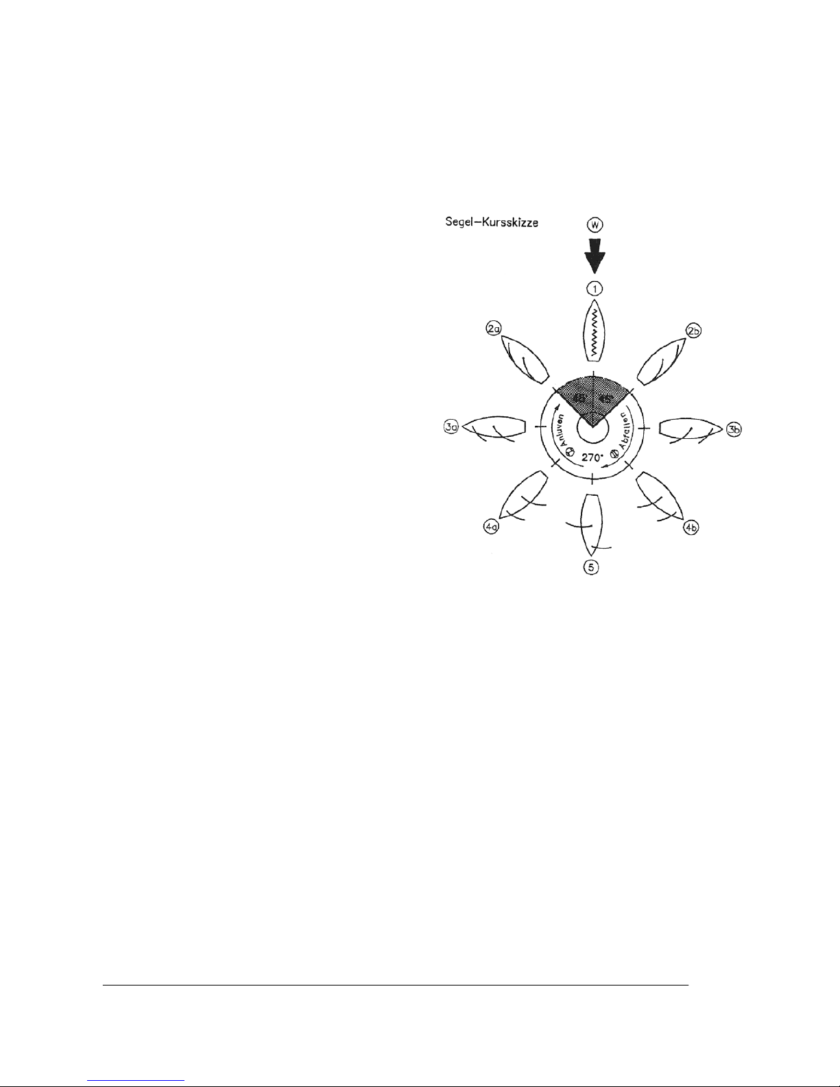
Die verschiedenen Segelkurse (siehe Skizze/Fachausdrücke kursiv geschrieben)
Ein Segelboot kann niemals gegen den Wind segeln
(schwarzer Pfeil (W)). In dem Bereich von 90°
(dunkelgraue Fläche) werden die Segel immer flattern
(killen) und so keinen Vortrieb leisten können. Erst wenn
das Boot ca. 45° von der Windrichtung abgefallen ist,
wird es bei dichtgeholten Segeln zu fahren beginnen
(Übergang dunkelgrau zu hellgrauer Fläche (2a) bzw.
(2b)). Diesen Kurs nennt man am Wind segeln. Nur auf
diesem Kurs und mit dichtgeholten Segeln kann ein
Segelboot durch das sogenannte Kreuzen gegen den
Wind segeln. Es segelt dazu einen Zickzackkurs: einige
Zeit auf Backbordbug (Großsegel auf der linken
Bootseite (2a)) und dann nach einer Wende (Boot wird
mit dem Bug durch den Wind gedreht, von Stellung (2a)
über (1) auf (2b)), einige Zeit auf Steuerbordbug
(Großsegel auf der rechten Bootsseite (2b)) usw.. Das
effektive schnelle Kreuzen mit einem Segelboot verlangt
viel Fingerspitzengefühl und Beobachtung und gilt als
eigentliche Kunst des Segelns.
Die anderen Kurse sind weniger anspruchsvoll. Wenn
der Wind von der Seite kommt, werden die Segel gerade
so weit geöffnet (gefiert), dass sie nicht flattern, etwa 30
bis 45° zur Bootslängsachse. Diesen Kurs nennt man
mit halbem Wind segeln ((3a) halber Wind auf
Backbordbug/(3b) halber Wind auf Steuerbordbug).
Wenn das Boot noch weiter abfällt (Abfallen: Boot mit
dem Heck immer mehr in Windrichtung drehen(II)/Anluven: Boot mit dem Bug immer mehr in Windrichtung
drehen(I)) gelangt es auf den raumen Kurs, bei dem die Segel auf ca. 60° zur Bootsmitte gefiert werden
(4a/4b). Nur auf diesen beiden Kursen kann die max. Bootsgeschwindigkeit erreicht werden.
Segelt das Boot direkt vom Wind weg, spricht man vom vor dem Wind segeln. Hierbei sollen die Segel max.
gefiert werden (ca. 90° zur Bootslängsachse). Durch verschiedene Druckverhältnisse der Segel wird hier das
Vorsegel von alleine auf die dem Großsegel gegenüberliegende Seite drehen. Dieser Vorgang kann durch
kleine Ruder-/Kurskorrekturen bewusst hervorgerufen werden. Wenn der Wind zu stark wird bzw. ist, kann ein
Segelboot dabei sehr leicht mit dem Bug unter Wasser gedrückt werden.
Wenn das Boot von einem raumen Kurs segelnd durch Ruderlegen in die vor dem Wind Stellung gebracht wird
(abfallen) und dann durch weiteres Ruderlegen wieder auf einen raumen Kurs (ca. rechtwinklig zum alten
raumen Kurs) gesteuert wird, fährt das Boot eine Halse. Die Halse gilt als vollzogen, wenn der weit gefierte
Großbaum von einer Bootsseite auf die andere Bootsseite schwingt.
Steuerverhalten/Segelverhalten
Durch wechselnde Winddrücke wird ein leistungsorientiertes Segelboot nicht von alleine seinen Kurs
beibehalten, sondern z.B. bei einer Windböe von alleine mehr oder weniger stark anluven, d.h. in den Wind
drehen. Dies kann man nur verhindern, indem rechtzeitig die Segel leicht gefiert werden und dazu ggf. auch
leicht Gegenruder gegeben wird, bis die Böe vorbei ist. Wenn das Boot abfallen soll, so sind neben der dazu
nötigen Ruderbewegung auch gezielt simultan die Segel zu fieren. Bei stärkerem Wind fährt sonst das Boot
trotz entsprechender Ruderbewegung relativ stur einfach weiter geradeaus. Bei zu kräftigem Wind wird jedes
Segelboot unkontrollierbar in den Wind drehen. Die Segelfläche ist dann zu groß; wenn kein alternativ kleineres
Segel zur Verfügung steht, ist ein Segeln nicht mehr möglich.
HINWEIS: Die beiden Seitenkiele werden beim Einsatz nicht benötigt und bremsen eher, fahren Sie daher
ohne diese. Das Vorbild des Modells stellt ein Typschiff dieser Klasse dar und daher sind diese aus optischen
Gründen auch am Modell vorhanden, obwohl sie hier fahrtechnisch nicht benötigt werden.
Page 8
GRAUPNER GmbH & Co. KG D-73230 KIRCHHEIM/TECK GERMANY
Keine Haftung für Druckfehler. Technische Änderungen vorbeha lten! Liability fo r printing errors exclud ed. We reserve the right to introduce modifications. Sous réserve de modifications!
Nous ne sommes pas responsables d’éventuelles erreurs d’impression!
#0060946
08/2009
8
Segeltrimm
Das Vorsegel soll im dichtgeholten Zustand (Großsegel ca. 10° mittschiffs) stets etwas offener als das
Großsegel eingestellt sein, also ca. 12° dichtgeholt sein, damit der Luftstrom vom Vorsegel nicht in das
Großsegel, sondern auf dessen Rückseite gelenkt wird. Dies ist je nach Wind und Wetter unterschiedlich und
kann bei der LIFE AT THE EXTREME durch Verstellen der Schoten und Fixieren an den Klampen entweder
am Groß- oder Fockbaum eingestellt werden.
Wenn das Boot bei konstant gleichmäßigem, leichten Wind und leichter
Schräglage (Kränkung) auf Halbwind-Kurs/Am-Wind-Kurs nicht seinen Kurs
hält, so stimmt der Riggtrimm nicht, d.h. der gemeinsame Segeldruckpunkt
muss verändert werden. Dies erreicht man bei der LIFE AT THE EXTREME,
z.B. durch Verstellen der Mastneigung (Modelldarstellung rechts
exemplarisch):
Situation/Verhalten Lösung/Einstellung
Luvgierig (Boot dreht von alleine
tendenziell in den Wind (es luvt
an))
Der Mast ist zu sehr nach hinten
geneigt und muss mehr nach vorne
gekippt werden (Achterstag lösen,
Vorstag anziehen)
Leegierig (Boot dreht von alleine
tendenziell aus dem Wind (es
fällt ab))
Der Mast ist zu sehr nach vorne
geneigt und muss mehr nach hinten
gekippt werden.
Achtung: Luv-/Leegierigkeit wird auch durch die Segeleinstellung beeinflusst,
etwa wenn das Großsegel mit dem Niederholer zu straff eingestellt wird, oder
das Vorsegel zu dicht/zu offen eingestellt ist.
Im Allgemeinen ist ein Segelboot mit einer leichten Luvgierigkeit am
leistungsfähigsten. Diese optimale Einstellung muss durch eigene Versuche
ermittelt werden, und ist nicht für jedes Wetter gleich.
Jungfernfahrt
Wählen Sie einen Tag mit optimalen Windverhältnissen und ein Gewässer aus wo Sie das Modell leicht bergen
können. Laden Sie die Akkus und testen Sie die Funktionen des Modells. Kontrollieren Sie, ob alle Teile fest
sitzen. Nun können Sie die Jungfernfahrt starten. Lassen Sie es bei der Jungfernfahrt vorsichtig angehen,
machen Sie sich erst mit dem Fahrverhalten vertraut. Fahren Sie nicht zu weit weg vom Ufer.
Viel Spaß beim Fahren mit Ihrem Modell LIFE AT THE EXTREME.
Ferner wird benötigt (nicht im Lieferumfang enthalten)
Empfohlenes Zubehör
Best.-Nr. Bezeichnung
3426 Graupner Alkaline Mignon (Typ AA) Trockenbatterie für Sender und Empfängerstromversorgung (insgesamt 12 Stück
erforderlich)
Optionales Zubehör (anstatt Trockenbatterien)
Best.-Nr. Bezeichnung
8716.BEC Empfängerakku 4N-1600 A, 4,8V, 1,6Ah
2498 Senderakku Enekeep 1N-2000 NiMH RTU, 1,2V, 2,0Ah (8 Stück erforderlich)
Ein passendes Ladegerät mit Ladebox wird benötigt, da die Ladebuchse im Sender nicht mit den Ladekabeln von Graupner kompatibel ist!
Erkunden Sie sich hierzu bei Ihrem Fachhändler.
Ersatzteile
Best.-Nr. Bezeichnung
2131.2 Rumpf
2131.3 Abdeckung (2 Stück)
2131.5 Ruderanlage (2 Stück)
2131.6 Kiel mit Zusatzkielen
2131.7 Segelsatz
Page 9

GRAUPNER GmbH & Co. KG D-73230 KIRCHHEIM/TECK GERMANY
Keine Haftung für Druckfehler. Technische Änderungen vorbeha lten! Liability fo r printing errors exclud ed. We reserve the right to introduce modifications. Sous réserve de modifications!
Nous ne sommes pas responsables d’éventuelles erreurs d’impression!
#0060946
08/2009
9
Operating instructions for the model boat LIFE AT THE EXTREME, Order No.: 2131
Brief description of the model
• Kit containing ready-made components (ARTR)
• Quick to assemble; no parts have to be trimmed or adjusted
• GRP hull, already painted
• Rig consisting of black anodised aluminium profiles
• Ballast weight already fitted in keel
• Printed sails
• Model supplied complete except for RC components and batteries
• The model can be completed, ready to sail, in one weekend
• Light-wind sailing boat: up to wind strength 3
• Set contents: hull, hatch covers, keel, supplementary keels, rudder system (everything pre-painted),
powerful sailwinch, rudder servo, receiver, transmitter, battery box and switch, injection-moulded plastic
and pressure-cast zinc fittings, aluminium boatstand, small items.
Specification
Overall length approx. 950 mm
Beam approx. 200 mm
Overall height approx. 1550 mm
All-up weight approx. 3.05 kg
Overall sail area approx. 4100 cm²
Manufacturer’s declaration from Graupner GmbH & Co. KG
Content of the manufacturer’s declaration:
If material defects or manufacturing faults should arise in a product distributed by us in the Federal Republic of
Germany and purchased by a consumer (§ 13 BGB), we, Graupner GmbH & Co. KG, D-73230 Kirchheim/Teck,
Germany, acknowledge the obligation to correct those defects within the limitations described below.
The consumer is not entitled to exploit this manufacturer’s declaration if the failure in the usability of the product
is due to natural wear, use under competition conditions, incompetent or improper use (including incorrect
installation) or external influences.
This manufacturer’s declaration does not affect the consumer’s legal or contractual rights regarding defects
arising from the purchase contract between the consumer and the vendor (dealer).
Extent of the guarantee
If a claim is made under guarantee, we undertake at our discretion to repair or replace the defective goods. We
will not consider supplementary claims, especially for reimbursement of costs relating to the defect (e.g.
installation / removal costs) and compensation for consequent damages unless they are allowed by statute.
This does not affect claims based on legal regulations, especially according to product liability law.
Guarantee requirements
The purchaser is required to make the guarantee claim in writing, and must enclose original proof of purchase
(e.g. invoice, receipt, delivery note) and this guarantee card. He must send the defective goods to us at his own
cost, using the following address:
Gliders
Brunel Drive, Newark, Nottinghamshire, NG242EG
The purchaser should state the material defect or manufacturing fault, or the symptoms of the fault, in as
accurate a manner as possible, so that we can check if our guarantee obligation is applicable.
The goods are transported from the consumer to us and from us to the consumer at the risk of the consumer.
Page 10

GRAUPNER GmbH & Co. KG D-73230 KIRCHHEIM/TECK GERMANY
Keine Haftung für Druckfehler. Technische Änderungen vorbeha lten! Liability fo r printing errors exclud ed. We reserve the right to introduce modifications. Sous réserve de modifications!
Nous ne sommes pas responsables d’éventuelles erreurs d’impression!
#0060946
08/2009
10
Duration of validity
This declaration only applies to claims made to us during the claim period as stated in this declaration. The
claim period is 24 months from the date of purchase of the product by the consumer from a dealer in the
Federal Republic of Germany (date of purchase). If a defect arises after the end of the claim period, or if the
evidence or documents required according to this declaration in order to make the claim valid are not presented
until after this period, then the consumer forfeits any rights or claims from this declaration.
Limitation by lapse of time
If we do not acknowledge the validity of a claim based on this declaration within the claim period, all claims
based on this declaration are barred by the statute of limitations after six months from the time of
implementation; however, this cannot occur before the end of the claim period.
Applicable law
This declaration, and the claims, rights and obligations arising from it, are based exclusively on the pertinent
German Law, without the norms of international private law, and excluding UN re tail law.
Important safety notes
You have purchased a kit which can be assembled to produce a fully working RC model when fitted out with
the appropriate accessories. As manufacturers, we at GRAUPNER are not in a position to influence the way
you install, operate and maintain the model, nor the other components used in connection with the model. For
this reason we are obliged to deny all liability for loss, damage or costs which are incurred due to the
incompetent or incorrect use and operation of our products, or which are connected with such operation in any
way. Unless otherwise prescribed by binding law, the obligation of the GRAUPNER company to pay
compensation, regardless of the legal argument employed, is excluded. This includes personal injury, death,
damage to buildings, loss of trade or turnover, interruption of business or other indirect or direct damages which
are caused by the operation of the model.
Under all circumstances and in all cases the company’s overall liability is limited to the amount which you
actually paid for this model.
The model is operated at the sole risk of the operator. To avoid injury to persons and damage to
property please handle your model boat carefully and operate it conscientiously at all times.
Before you run the boat for the first time it is important to check that your private third party insurance policy
provides cover when you are operating model boats of this kind. If you are not sure, take out a special
insurance policy designed to cover the risks of RC modelling.
These safety notes are important, and must be kept in a safe place. If you ever dispose of the model, be sure to
pass them on to the new owner.
The following points are important and must be observed at all times:
• This model is not suitable for young persons under fourteen years of age.
• The keel ballast is made of lead! When you have finished with the model, it is essential to dispose of the
lead weight in accordance with legal requirements; it must never be discarded in the household waste. If
you are not sure where you can take scrap lead, ask your local authority for information (usually communal
recycling centres).
• The projecting parts of the model may be sharp, and the aerials and masts may cause eye injuries.
• If the model is to be built by a youngster, a parent or guardian must monitor the assembly process, as tools
and adhesives can be hazardous.
• Please operate the model carefully when there are persons or animals in the water; always keep a safe
distance between the boat and man or beast.
• Never run your boat in a protected site, an animal or plant sanctuary or a site of special scientific interest
(SSSI). Check with your local authority that the stretch of water you wish to use is suitable for model boats.
• Never sail the model in salt water.
• Never run your boat in adverse conditions, e.g. rain, storm, strong wind (above Beaufort 4), choppy water
or strong currents.
• As the model is propelled solely by the wind, it should only be sailed in wind strengths of 1 to 3 on the
Beaufort scale (leaves moving in the wind). If the wind is stronger, the boat could heel severely and be
impossible to control. Gusty conditions should also be avoided.
• The model requires a breeze in order to move, i.e. in flat calm conditions the boat will just remain stationary
on the water. Please bear this in mind before sailing the model.
• Before you operate the boat, please check that the radio control system is working reliably.
Page 11

GRAUPNER GmbH & Co. KG D-73230 KIRCHHEIM/TECK GERMANY
Keine Haftung für Druckfehler. Technische Änderungen vorbeha lten! Liability fo r printing errors exclud ed. We reserve the right to introduce modifications. Sous réserve de modifications!
Nous ne sommes pas responsables d’éventuelles erreurs d’impression!
#0060946
08/2009
11
• It is important to check the range of the radio control system: switch the radio control system on, hold the
transmitter in your hands, and walk about 50 m away from the boat. All the radio-controlled functions
should continue to work normally at this range. Note: in optimum conditions the maximum range is up to 75
m.
• Ensure that the channel you intend to use is not already occupied by another modeller. Never run the boat
if you are not certain that your channel is free.
• Note that other radio equipment and transmitting stations may cause serious interference to the model’s
receiving system. If possible, ensure that no such apparatus is in use in the vicinity while you are operating
the boat.
• Switch the model’s radio system off before carrying out any work on the boat.
• Dry cells and rechargeable batteries must never be short-circuited, nor allowed to come into direct contact
with water.
• Remove all batteries from the model and the transmitter when you know you will not be using them in the
near future.
• The transmitter’s integral charge socket is not compatible with standard Graupner charge leads. Please ask
for advice at your model shop if you wish to use rechargeable batteries in the transmitter; the staff will be
able to recommend a suitable combination of a Graupner charger and a charging box for the batteries.
• Do not subject the model to high levels of humidity, heat, cold or dirt.
• Secure the model and the transmitter when transporting them, as they may be seriously damaged if they
are free to slide about.
• Never operate the model on moving water (e.g. a river), as it could easily be washed away downstream if
the wind conditions change.
• If you have to salvage the model, take care not to risk your own life or that of others.
• Check regularly that the boat is completely watertight, as it may sink if too much water enters the hull.
Check the model for damage before every run, and ensure that water cannot penetrate the hull.
• Allow the boat to dry out thoroughly after use.
Care and maintenance
• Clean the model carefully after every run, and remove any water which gets inside the hull. If water gets
into any of the RC components, dry them out and send them to your nearest GRAUPNER Service Centre
for checking.
• Clean the model and the transmitter using suitable cleaning agents only. We recommend wiping with a lint-
free cloth. Never use chemical cleaners, solvents, petrol, white spirit or similar.
The radio control equipment
• Insert the dry batteries in the transmitter with correct polarity. Switch the transmitter on,
and the LEDs on the front panel will light up.
• Always switch the transmitter on first, and only then the receiver.
• Always switch the receiver off first, and only then the transmitter.
• Check that the model’s working s ystems operate correctly: if the direction of operation of
any function does not meet your wishes, you can change it using the servo reverse
switches on the transmitter: these are the small black switches which are protected from
accidental operation by the chromed bar.
• Never run your model boat with flat batteries in the transmitter or the model. The
batteries in the model have to “work harder”, and you can expect them to be exhausted
earlier. They must therefore be replaced before the transmitter batteries. If you are not
sure whether the batteries still hold enough charge, it is always best to replace them with
new ones. Many shops
have battery testers
which you can use to
check your own batteries.
Which LED glows Meaning of the LED indicators
All LEDs glow Transmitter batteries in good condition;
transmitter ready for use
Only red and orange
LEDs glow
Transmitter batteries almost flat; prepare to
cease operations and replace batteries
Only red LED glows Transmitter batteries completely discharged;
cease operations immediately and replace
batteries
Page 12

GRAUPNER GmbH & Co. KG D-73230 KIRCHHEIM/TECK GERMANY
Keine Haftung für Druckfehler. Technische Änderungen vorbeha lten! Liability fo r printing errors exclud ed. We reserve the right to introduce modifications. Sous réserve de modifications!
Nous ne sommes pas responsables d’éventuelles erreurs d’impression!
#0060946
08/2009
12
Notes on building the model
• When assembling the model please refer to the sketches in the supplementary English instructions.
• These instructions should be considered as complementary to the illustrated instructions. It contains the
essential translations together with additional notes and tips for assembling and operating the boat.
• If you do not understand the technical terms relating to sailing boats, you can download a sketch showing
the basic terminology from the Internet site www.micromagic-rc-segeln.de.
• Before you start building the boat, please take the time to study the plan and read right through the
instructions. In general terms the instructions reflect the sequence of assembly.
• TIP: the rigging cord is easier to thread through small holes and openings if you first apply a drop of cyano
to the end to harden it, then cut off the frayed extremity.
• Please bear in mind that many tools can be dangerous if misused or handled carelessly.
• Deploy the receiver aerial as high up in the hull as possible, and wind the wire outside the hull around one
of the shrouds. Reception will be very poor if the aerial is positioned below the waterline, and effective
range will be greatly reduced.
• It is important to clean the joint surfaces carefully before gluing parts together. This is best accomplished
by sanding lightly, followed by wiping with a non-greasy liquid detergent or methylated spirit (“meths”). The
same applies to all surfaces which are to be painted, as this improves the paint’s adhesion considerably.
• Each bag containing small items and screws bears a printed number which is also shown in the assembly
drawings.
• You will find the part numbers of the injection-moulded parts on a small plate adjacent to the individual part
on the sprue; the numbers will help you identify and allocate the plastic parts. Some of the injectionmoulded parts are readily identifiable, and these have no number plate, as they can be allocated easily by
referring to the stage sketches.
• We recommend that you use high-viscosity cyano-acrylate (‘thick cyano’, e.g. Order No. 5821) for all joints
on this model.
Assembly instructions
• Assemble the boatstand as shown. TIP: the holes in the bands can easily be pierced using a heated length
of metal wire; a match is quite sufficient to heat it. Be sure to produce one frame with long cross-pieces and
one with short cross-pieces.
• Loosen the sheets (the pre-fitted black cords in the hull) and stick them to the outside of the hull using
adhesive tape, to ensure that they cannot slip back inside the hull during the following stages.
• Screw the ring holders (D07) and the cleat (D08) to the hull. NOTE: take care not to over-tighten the
screws. Screw in place the holders (D03) for the lateral keels. NOTE: ensure that the small triangles of the
ratchet face outwards (see enlarged area of the sketch). Finally screw the latches (D01) to the hull; ensure
that they are able to rotate smoothly.
• Stick the large RC box to the inside of the hull using double-sided adhesive tape. The correct position is
approximately central under the sheet guide.
• Screw the spacers to the winch holder plate, then fix this assembly in the hull using the screws provided.
• Fit the rubber gaskets on the rudder bushes, pass the bushes through the hull from the underside, then fit
the sleeves. Attach the spacer to the rudder servo holder, place this assembly on the rudder bushes, and
screw the winch holder in place. TIP: it is advisable to seal the rudder bushes on the inside with glue; we
particularly recommend an adhesive such as UHU alleskleber, as this glues the bushes in place as well as
sealing them against water penetration.
• Press the rubber grommets into the winch mounting lugs, and push the metal spacer sleeves into the
grommets before screwing the winch to the winch holder. Please refer to the sketch for the following steps,
as it shows the exact position of the parts. Fit batteries in the transmitter and receiver battery box, and
switch both units on; set the winch to centre from the transmitter.
• Screw the winch drum to the winch, first running the two sheets through the guide ring and then winding
both of them 1.5 times round the drum. Push the ends into the drum and tie them together. NOTE: ensure
that the sheets are allocated correctly between the drum and the ring; they must not cross over. Secure the
knot by tightening the retainer (E12). Screw the guide ring in place.
• The winch assembly can now be screwed to the winch support plate. NOTE: ensure that the winch
connecting lead is still accessible. TIP: this can be achieved simply by taping it to the hull side.
• Attach the guide sleeves to the servo output lever (D02). Cut off the three unwanted arms from the four-
armed servo output lever, then screw a guide sleeve to the remaining arm (see sketch for position). Screw
the rudder servo to the rudder servo mount, after fitting the small box under the servo. The box does not
need to be glued in place, as it is held in position by the servo itself. Route the servo lead through the hull
as shown in the sketch.
• Lubricate the rudder shafts with grease, slide them through the rudder bushes and push the tillers onto the
Page 13

GRAUPNER GmbH & Co. KG D-73230 KIRCHHEIM/TECK GERMANY
Keine Haftung für Druckfehler. Technische Änderungen vorbeha lten! Liability fo r printing errors exclud ed. We reserve the right to introduce modifications. Sous réserve de modifications!
Nous ne sommes pas responsables d’éventuelles erreurs d’impression!
#0060946
08/2009
13
top end of the shafts. Secure the rudders with the two clamps by pushing them through the holes in the
rudder shafts.
• Fit the rudder pushrod onto the guide sleeves. NOTE: ensure that the position is exactly as shown. Set the
rudder servo to centre, using the procedure outlined for the winch. The output lever can now be screwed to
the servo.
• Install the keel in the hull and fit the retaining nut to secure it.
• Connect the leads attached to the winch, the rudder servo and the switch to the receiver, as shown in the
sketch. Check that the channel sequence is correct, i.e. that each transmitter control really does operate
the corresponding function. When you are satisfied, place the receiver in a small plastic bag and secure the
opening with a rubber band or adhesive tape. NOTE: the bag must not be watertight, otherwise
condensation may form inside it.
• Tie the aerial wire to the thin thread and use the thread to draw the wire through the hull. You can remove
the thread and discard it once the aerial is outside the hull. NOTE: since the opening through which the
knot has to be threaded is only 3 mm in size, you must ensure that the knot is not too large. TIP: tape the
wire to prevent it slipping back into the hull.
• Insert a winch crank in one holder (C08) and then glue the mating piece (C09) on top. Screw the holders to
the forward cockpit plate, then screw the two holders (C12) to the underside of the plate.
• Screw the base plate to the lower radar ball, then glue the upper ball on top. Screw the radar balls to the
rear cockpit plate before screwing the two holders (C12) to the underside of the plate.
• Screw the winch base components (C03, C05 and C07) to the hull; take care to allocate the base parts
correctly.
• Glue the winch hatch covers (C02, C04 and C06) to the base components.
• Connect the three winches using the 1.5 mm Ø cord, as shown in the sketch.
• Glue the two braces (C01) to the underside of the cross-strut, roughen the pins and glue them in the strut
before installing this assembly in the hull.
• Glue two of the roughened pins in the ship’s wheel holder (C11), then glue the mating piece (C10) on top
before attaching a ship’s wheel to each of the black metal pins. NOTE: remember to produce a pair of
mirror-image ship’s wheels, as shown in the sketch. Glue the two ship’s wheels to the hull.
• The bow pulpit and the two stern pulpits can now be glued to the hull, followed by the railing stanchions.
NOTE: ensure that all the holes in the stanchions for the railing cords lie parallel to the outside edge of the
hull. NOTE: the long railing stanchion should be fitted at the stern.
• Cut the railing cords to the required lengths, thread them through the holes in the stanchions, and tie the
ends to the bow and stern pulpits; secure the knots with a drop of glue. NOTE: the railing cords should not
be so slack as to hang down, but on the other hand do try to keep the tension in all of the cords slight. On
no account should the tension be excessive, otherwise the cords might pull the pulpits out of the hull.
• Screw a support (E09) to the inner main boom fitting (E07), then glue the two fittings (E07 and E08) to the
main boom. Screw the ring holders (E11) and the ball holder (E11) to the boom, then fix the cleat (D08) to
the side of the boom.
• Fit the spacer between the two main boom holders (E05 and E06), then screw the boom in place
permanently. Attach a ball-link (D04) to each end of the threaded rod, and screw the ball-links in or out to
set the correct length: the distance between the links should be 73 mm. Press a linkage ball into each balllink and attach this assembly (known as the kicking strap) to the main boom and the bottom fitting.
•
Screw one short spreader to the upper mast section. NOTE: take care to position the spreader correctly.
Now screw the ring holder (D07) to the mast and install the mast head.
• Screw the longest spreader and the middle spreader to the mast, again taking care to position these parts
correctly. NOTE: the underside of the mast is the end with the two holes. Fit the two mast sections together
and secure them with the retaining screw.
• IMPORTANT: to carry out the following steps correctly it is essential that you understand the procedure
fully. We therefore recommend that you first study the sketch in the supplementary instructions in peace
and quiet. Cut the following lengths from the 1.0 mm Ø cord: 1 x 146 cm, 4 x 64 cm and 4 x 40 cm. Fold the
146 cm length of cord in half, tie it to the front of the mast head, then pass the ends through the upper
spreader. Pass them through the next spreader, then through the rings, back through the spreader again,
and tie them to the mast at the upper spreader. NOTE: ensure that there is adequate and even tension
throughout the cord: the tension is correct when the cords reliably hold the mast assembly together, but do
not pull it out of shape. The same applies to all the following stages of assembling the rigging.
• Tie a 64 cm length of cord to each of the rings, pass it through the lower spreader, then through a ring
again and tie the cord permanently to the upper spreader on the inside. Repeat this procedure for the next
section of the mast, moving down. Tie a 40 cm length of cord to each of the rings, run it inboard to the
spreader and pass the cord through a shroud tensioner (D06). Route the cord through the hook (cut-away
ring) and tie it as shown in the drawing.
• Glue the sail battens to the mainsail as shown in the sketch. The light-coloured areas of the sail indicate
Page 14

GRAUPNER GmbH & Co. KG D-73230 KIRCHHEIM/TECK GERMANY
Keine Haftung für Druckfehler. Technische Änderungen vorbeha lten! Liability fo r printing errors exclud ed. We reserve the right to introduce modifications. Sous réserve de modifications!
Nous ne sommes pas responsables d’éventuelles erreurs d’impression!
#0060946
08/2009
14
where the sail battens are to be glued; the lengths of the individual battens are shown in the sketch.
• Slide the mainsail into the mast channel and push or pull it up until the top end is just short of the mast tip.
Slide the main boom support onto the mast and screw the lower bearing to the mast. Adjust the position of
the sail until it is about 1 cm away from the main boom. Cut the following lengths from the 1.0 mm Ø cord: 1
x 64 cm, 1 x 40 cm and 1 x 16 cm. Tie the 16 cm long cord permanently to the bottom of the sail, pass it
through the hole in the spacer and tie the cord in such a way that the distance between the sail and the
boom is 1 cm. Tie the 64 cm length of cord to the top of the sail, pass it centrally through the mast head
and place the sail under light tension, winding the cord five or six times round the upper cleat before
securing it. Now tie the 40 cm length of cord permanently to the outside of the sail, and pass it through the
hole in the outer main boom fitting (E08). Fit a shroud tensioner (D06) and a hook on the cord, then tie it in
place as described earlier for the mast.
• Glue the two end fittings (E10) to the jib boom. IMPORTANT: the flat areas of the fittings must lie in the
same plane. Screw the ring holders (D07) and the cleat (D08) to the jib boom.
• Glue the sail battens to the jib as shown in the sketch. The light-coloured areas of the sail indicate where
the sail battens are to be glued; the lengths of the individual battens are shown in the sketch.
• Cut the following lengths from the 1.0 mm Ø cord: 1 x 340 cm, 1 x 64 cm, 1 x 40 cm and 1 x 16 cm. Tie the
jib cord (forestay) to the end fitting at the front extremity of the jib boom. Tie the 40 cm length of cord to the
rear end of the jib sail, run it through the inner end fitting, then through a shroud tensioner (D06) and hook
before connecting them together, as described earlier for the mast. Tie the 64 cm length of cord (extension
of the forestay) to the ring holder on the jib boom, then tie the 16 cm length of cord to the top of the jib. Fit a
shroud tensioner (D06), thread the cord through the ring holder on the mast, and wind the cord five or six
times around the cleat.
• Fold the 340 cm length of cord in half and tie it to the mast head. Run both ends through a shroud
tensioner (D06) and a hook, and secure it as described for the mast. These lengths of cord act as the
backstay.
• Insert the mast into the mast socket on the hull. Connect the shroud ends (hooks) to the ring holders on the
deck, and tighten them to the point where the mast stands firmly on the deck. Connect the hooks on the
backstay, and run the extension of the forestay through the ring holder. Tension the two stays to the point
where the mast stands at a very slight angle (rake) towards the stern; you may need to adjust the tension in
the shrouds at this point. IMPORTANT: since all of the winch power is transmitted to the hull via the
shrouds and stays these must always be tensioned uniformly, otherwise they will not share the force
transmission evenly.
• Run the two sheets through the appropriate ring holders, and adjust the sails so that their settings can be
varied using the transmitter stick. NOTE: the sails must not prevent the sailwinch moving (motor stalled) in
the close-hauled state, i.e. when close-hauled, the sails should lie as close as possible to centre relative to
the hull centreline, but without being under tension. The travels stated in the supplementary instructions
can be adopted as the basic settings, while the ideal values can be “learned” later during the test-running
procedure. The next few sections of these instructions are intended as a general guide for optimising the
model, and are based on our own experience. These sections also explain particular procedures when
sailing, and are aimed at helping the beginner to model sailing achieve a good overall set-up of the model
quickly and easily.
• NOTE: the supplementary lateral keels should only be used in fairly strong winds, as they tend to slow the
boat down in light breezes.
Page 15

GRAUPNER GmbH & Co. KG D-73230 KIRCHHEIM/TECK GERMANY
Keine Haftung für Druckfehler. Technische Änderungen vorbeha lten! Liability fo r printing errors exclud ed. We reserve the right to introduce modifications. Sous réserve de modifications!
Nous ne sommes pas responsables d’éventuelles erreurs d’impression!
#0060946
08/2009
15
Sailing
Sailing a model yacht is not difficult once you are familiar with the inter-action between the wind direction, the
boat’s heading and the appropriate sail settings. Before you sail the model for the first time, we recommend that
you read all you can on the theory of sailing, e.g. by reading one of the many books on the subject. The
following section just provides a short, basic introduction to the subject.
The various points of sailing (see sketch; specialist terms are printed in Italics)
A sailing boat can never sail directly into wind (black
arrow (W)). In the 90° sector (dark grey area) the sails
will always flutter (shiver), and generate no forward
thrust. Only when the boat bears away to about 45° off
the wind direction will it start to pick up speed with the
sails close-hauled (transition from dark grey area to
light grey area (2a) to (2b)). This course is termed
luffing. A sailing boat can only make headway into the
wind on this course and with the sails close-hauled;
the procedure is known as tacking, and involves
sailing in a zig-zag pattern: for a while on the port tack
(mainsail on the left-hand (port) side of the boat (2a)),
then, after going about (the boat’s bow turns through
the wind, from position (2a) via (1) to (2b)), for a while
on the starboard tack (mainsail on the right-hand
(starboard) side of the boat (2b)), etc. Fast, efficient
tacking with a sailing boat demands a good eye and
considerable manual skill, and ranks as the true art of
sailing.
The other courses are not so demanding. If the wind is
blowing from the side, the sails are slackened (run
out) just to the point where they no longer shiver, i.e.
around 30° to 45° relative to the boat’s longitudinal
axis. This course is known as sailing with wind abeam
((3a) wind abeam on the por t bow / (3b) wind abeam
on the starboard bow).
If the boat bears away even further (bearing away: the boat turns away from the wind, i.e. the stern turns
increasingly in the direction of the wind (II) / luffing: the boat’s bow turns increasingly towards the direction of
the wind (I), ending up on a course with free wind, where the sails are paid out to about 60° to the boat’s
centreline (4a / 4b). The boat only attains its maximum speed on these two headings.
If the boat is sailing directly away from the wind (downwind), we speak of running before the wind. On this
course the sails should be paid out as far as possible (approx. 90° to the boat’s centreline). Differential
pressure conditions on the sails cause the jib to turn to the opposite side to the mainsail by itself, but this
situation can also be generated deliberately by small rudder / course corrections. If the wind is or becomes too
strong, the bow of a sailing boat can very easily be pushed under the water.
If the boat is sailing with free wind, is brought into a position before the wind using the rudder (bearing away),
and is then steered back to a free wind heading using the rudder (approximately at right-angles to the former
course with free wind), the boat is said to have performed a gybe. Gybing is complete when the main boom,
paid out a long way, swings from one side of the boat to the other.
Steering characteristics / Sailing characteristics
Variations in wind pressure make it difficult for a performance-orientated sailing boat to maintain its course by
itself; gusts of wind may cause it to luff up by itself, i.e. turn into the wind to a greater or lesser extent. This can
only be prevented by running out the sails slightly in good time, and also by applying slight opposite rudder if
necessary, until the gust is past. If the boat should bear away, the sails should be slackened at the same time
as the necessary corrective rudder movement is applied. Otherwise, in fairly strong winds the boat will tend
simply to continue stubbornly in a straight line, ignoring the corrective rudder commands. Please note that any
sailing boat will turn uncontrollably into the wind if the breeze is too powerful. This means that the sail area is
too great; if there is no alternative smaller sail suit available, sailing is not possible in these conditions.
NOTE: the two lateral keels are not needed when sailing the boat, and tend to slow it down, so you should
normally sail without them. The prototype of this model is a typical yacht of this class, and they are present on
the model so that it “looks the part”, although they are not necessary for sailing.
Page 16

GRAUPNER GmbH & Co. KG D-73230 KIRCHHEIM/TECK GERMANY
Keine Haftung für Druckfehler. Technische Änderungen vorbeha lten! Liability fo r printing errors exclud ed. We reserve the right to introduce modifications. Sous réserve de modifications!
Nous ne sommes pas responsables d’éventuelles erreurs d’impression!
#0060946
08/2009
16
Sail trim
The foresail of a yacht should always be slightly more open than the mainsail when close-hauled (mainsail
around 10° midships; foresail about 12° close-hauled) so that the airflow from the foresail is directed onto the
rear face of the mainsail, rather than being deflected into the front of it. The difference required varies according
to the wind and weather, and can be adjusted on the LIFE AT THE EXTREME by altering the sheet clamps,
either on the main boom or the jib boom.
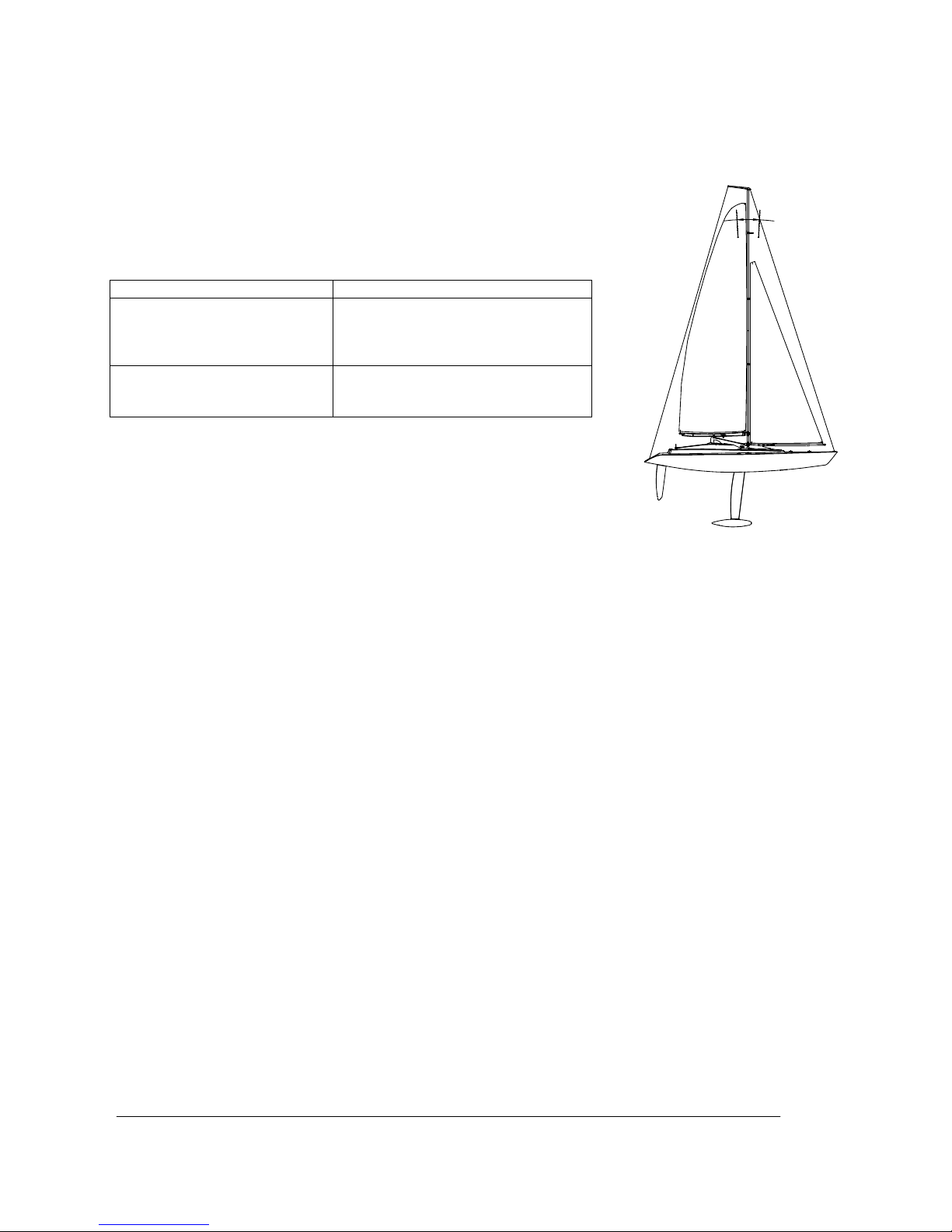
If the boat does not maintain its course in a constant light wind and at a
slight angle (heel) when luffing, then the trim of the rig is not correct, i.e. the
centre of pressure of the whole sail area needs to be altered. In the case of
the LIFE AT THE EXTREME this is achieved typically by adjusting the mast
rake (inclination):
Caution: a boat’s tendency to turn into or away from the wind is also
affected by the sail settings; for instance, if the mainsail is set too tight by
the kicking strap, or if the foresail is set too close-hauled or too far open.
In general terms sailing boats offer their maximum performance if they have
a slight windward tendency. The optimum setting can only be established by
experimenting; please bear in mind that it also varies according to the
weather conditions.
Maiden run
Wait for a day with optimum wind conditions, and seek out a stretch of water where you can easily salvage the
boat. Charge up the batteries, and check the model’s working systems. Ensure that all parts are securely
attached. Now you are ready for the boat’s maiden run. Be cautious at first, and take your time to get used to
the boat’s sailing characteristics and handling. Don’t sail the model too far from the bank initially.
All of us at GRAUPNER hope you have many hours of pleasure building and running your LIFE AT THE
EXTREME.
The following items are also required (not included in the kit)
Recommended accessories
Order No. Description
3426 Graupner Alkaline AA dry cell for transmitter and receiver power supplies (twelve cells required in
total)
Optional accessories (instead of dry cells)
Order No. Description
8716.BEC 4N-1600 A receiver battery, 4.8 V / 1.6 Ah
2498 Enekeep 1N-2000 NiMH RTU transmitter battery, 1.2 V / 2.0 Ah (eight cells required)
A suitable battery charger and charger box are required, as the transmitter’s charge socket is not compatible with standard
Graupner charge leads. Please ask as your model shop for details.
Replacement parts
Order No. Description
2131.2 Hull
2131.3 Hatch cover (2 off)
2131.5 Rudder system (2 off)
2131.6 Keel and supplementary keels
2131.7 Sail suit
Situation / Behaviour Solution / Adjustment
Windward tendency (the boat
tends to turn into the wind by
itself (it luffs up).
The mast is raked too far back, and
needs to be tilted forward (loosen
backstay, tighten forestay).
Leeward tendency (the boat
tends to turn away from the
wind by itself (it bears away).
The mast is raked too far forward,
and needs to be tilted further back.
Page 17

GRAUPNER GmbH & Co. KG D-73230 KIRCHHEIM/TECK GERMANY
Keine Haftung für Druckfehler. Technische Änderungen vorbeha lten! Liability fo r printing errors exclud ed. We reserve the right to introduce modifications. Sous réserve de modifications!
Nous ne sommes pas responsables d’éventuelles erreurs d’impression!
#0060946
08/2009
17
Instructions d’utilisation pour le modèle LIFE AT THE EXTREME, Réf. N°2131
Courte description du modèle
• Kit de montage avec pièces finies (ARTF)
• Rapide à monter, car aucune pièce ne devra être travaillée
• Coque en fibre de verre livrée peinte
• Gréement en profilés d’aluminium anodisés en noir
• Lest de quille fini et monté dans celle-ci
• Voiles imprimées
• Modèle complet jusqu’aux sources d’alimentation fournies
• Le modèle peut être mis en ordre de navigation dans l’espace d’un Week End
• Voilier pour vent léger, jusqu’à force 3 max.
• Livraison : Coque, recouvrements, quille, quille additive, ensembles gouvernail (tous livrés peints), puissant
treuil pour voiles, servo de gouvernail, récepteur, coffret pour accu avec interrupteur, pièces d’accastillage
injectées et en fonderie de zinc, support de bateau en aluminium et petites pièces.
Caractéristiques techniques
Longueur hors tout, env. 950mm
Largeur, env. 200mm
Hauteur totale, env. 1550mm
Poids total, env. 3,05 Kg
Surface totale de voiles 4100 cm²
Déclaration du fabricant de la Firme Graupner GmbH & Co. KG
Contenu de la déclaration
Lorsqu’un article que nous distribuons dans la République Fédérale d’Allemagne acquis par un consommateur
(§ 13 BGB) présente un défaut de matière ou de fabrication, nous la Firme Graupner GmbH & Co. KG,
Kirchheim Teck, prenons en charge la suppression du défaut de l’article dans les conditions ci après.
Le consommateur ne peut pas valider le droit de déclaration du fabricant lorsque le défaut de l’article provient
d’une usure naturelle, d’une utilisation dans des conditions de compétition, d’une mauvaise utilisation (incluant
le montage) ou d’influences extérieures.
Cette déclaration du fabricant laisse inchangés le droit et les réclamations légales ou contractuelles du
consommateur provenant du contrat d’achat vis à vis de son vendeur (le détaillant).
Etendue de la garantie
En cas de garantie, nous faisons le choix de réparer ou d’échanger la marchandise défectueuse. Toutes autres
réclamations, particulièrement sur le remboursement des coûts engendrés par le défaut (par ex. coûts de
montage/démontage) et la compensation de dommages provoqués en conséquence – même autorisés
légalement – sont exclues. Les réclamations provenant des réglementations légales, en particulier selon la loi
de la responsabilité du fabricant, ne seront pas ici abordées.
Droit à la garantie
L’acheteur peut faire valoir le droit à la garantie en joignant le bon d’achat original (par exemple facture, ticket
de caisse, bon de livraison) et cette carte de garantie. Il doit en outre retourner la marchandise défectueuse à
ses frais à l’adresse suivante :
GRAUPNER Service France
86 rue St Antoine
F-57601 Forbach-Oeting
L’acheteur doit indiquer concrètement le défaut de matière ou de fabrication ou le symptôme du défaut pour
permettre l’examen de notre devoir de garantie.
Le transport du produit de chez le consommateur à chez nous, tout comme le transport du retour se font aux
risques et périls du consommateur.
Page 18

GRAUPNER GmbH & Co. KG D-73230 KIRCHHEIM/TECK GERMANY
Keine Haftung für Druckfehler. Technische Änderungen vorbeha lten! Liability fo r printing errors exclud ed. We reserve the right to introduce modifications. Sous réserve de modifications!
Nous ne sommes pas responsables d’éventuelles erreurs d’impression!
#0060946
08/2009
18
Durée de validité
Cette déclaration est seulement valable pour la période accordée aux réclamations provenant de cette
déclaration. Le délai de réclamation est de 24 mois à partir de la date de l’achat du produit par le
consommateur chez un commerçant en République Fédérale d’Allemagne (date d’achat). Si les défauts sont
signalés après le délai de réclamation autorisé ou bien si les preuves ou les documents pour faire valoir les
défauts selon cette déclaration sont présentés après le délai de réclamation, l’acheteur n’a aucun droit de
réclamation ou requêtes en provenance de cette déclaration.
Prescription
Tant que nous ne reconnaissons pas la réclamation à faire valoir dans la période de réclamation accordée
dans le cadre de cette déclaration, l’ensemble des réclamations de cette déclaration sont prescrites pendant 6
mois à partir de leur validation, cependant pas avant la fin du délai de réclamation.
Droit applicable
Dans le cadre de cette déclaration et des réclamations, des droits et devoirs, qui en résultent, seul et
uniquement le Droit matériel allemand s’applique, sans possibilité d’utiliser les normes du Droit privé
international et celles de la Commission du Droit de vente des Nations Unies.
Conseils de sécurité importants
Vous avez fait l'acquisition d'une boite de construction avec les accessoires correspondants qui vont vous
permettre la réalisation d'un modèle radiocommandé. Le respect des instructions de montage et d'utilisation
relatives au modèle ainsi que l'installation, l'utilisation et l'entretien des éléments de son équipement ne
peuvent pas être surveillés par la Firme GRAUPNER. C'est pourquoi nous déclinons toute responsabilité
concernent les pertes, les dommages ou les coûts résultants d'une mauvaise utilisation ou d'un fonctionnement
défectueux. Tant qu'elle n'y a pas été contrainte par le législateur, la responsabilité de la Firme GRAUPNER
n'est aucunement engagée pour les dédommagements (incluant les dégâts personnels, les cas de décès, la
détérioration de bâtiments ainsi que le remboursement des pertes commerciales dues à une interruption
d'activité ou à la suite d'autres conséquences directes ou indirectes) provenant de l'utilisation du modèl e.
L'ensemble de sa responsabilité est en toutes circonstances et dans chaque cas strictement limité au montant
que vous avez réellement payé pour ce modèle.
L'utilisation du modèle se fait uniquement aux risques et périls de son utilisateur. Seule une utilisation
prudente et responsable évitera de causer des dégâts personnels et matériels.
Avant la première utilisation du modèle, vérifiez si votre assurance privée couvre ce genre de risque. Le cas
échéant, contractez une assurance spéciale pour les modèles radiocommandés .
Ces conseils de sécurité devront être soigneusement conservés et remis à l’acheteur en cas de vente du
modèle.
Les points suivants devront être impérativement observés:
• Ce modèle ne convient pas aux enfants en dessous de 14 ans.
• Le lest de quille est en plomb ! Vous devrez vous débarrasser éventuellement du plomb conformément aux
dispositions légales ; il ne devra jamais être jeté dans une poubelle domestique. Renseignez-vous auprès
de l’administration de votre commune pour savoir où le plomb peut être déposé (généralement dans des
containers communaux).
• Certaines pièces dépassant sur le modèle sont coupantes et les antennes ou les mâts peuvent causer des
blessures aux yeux.
• Les parents devront surveiller le montage du modèle par leur enfant, car des dangers peuvent survenir
avec l’utilisation des outils et des colles.
• Faites naviguer le modèle avec précaution lorsque des personnes et des animaux se trouvent dans l’eau.
Tenez-vous toujours à une distance suffisante des personnes et des animaux.
• Ne faites pas naviguer le modèle dans des eaux se trouvant dans une nature protégée. Informez-vous s'il
existe dans votre commune un plan d'eau autorisé pour la navigation des modèles de bateaux
• Ne naviguez jamais dans de l’eau salée.
• Ne naviguez jamais par de mauvaises conditions atmosphériques, par ex. sous la pluie, un orage, à partir
d’une force de vent 4 (Beaufort), sur une eau agitée ou avec un fort courant, etc…
• Comme le modèle est dépendant du vent, il devra naviguer uniquement par des forces de vent de 1 à 3
Beaufort (faibles mouvements des feuilles sur les arbres). Par un vent plus fort, le modèle pourra se
coucher sur le côté et devenir incontrôlable. Le modèle ne devra pas naviguer non plus lorsque le vent
souffle par rafales.
• La propulsion du modèle est uniquement le vent, c'est-à-dire que par temps calme il restera à l’arrêt sur
Page 19

GRAUPNER GmbH & Co. KG D-73230 KIRCHHEIM/TECK GERMANY
Keine Haftung für Druckfehler. Technische Änderungen vorbeha lten! Liability fo r printing errors exclud ed. We reserve the right to introduce modifications. Sous réserve de modifications!
Nous ne sommes pas responsables d’éventuelles erreurs d’impression!
#0060946
08/2009
19
l’eau ; ceci devra être pris en compte à chaque navigation.
• Avant de faire naviguer le modèle, vérifiez le parfait fonctionnement de l’ensemble R/C.
• La portée de l’installation R/C devra être vérifiée avant chaque séance de navigation. Pour cela, éloignez-
vous du modèle à env. 50 m avec la réception mise en contact et vérifiez avec l’émetteur si toutes les
fonctions se font sans problème. NOTE : Par des conditions optimales, la portée atteint jusqu’à 75 m !
• Vérifiez si la fréquence que vous utilisez est libre. Ne naviguez jamais tant que vous n’êtes pas sûr qu’elle
n’est pas déjà utilisée.
• Notez que des émetteurs radio ou d’autres émetteurs R/C peuvent fortement perturber le fonctionnement
du modèle. Veillez dans la mesure du possible à ce qu’aucun de ces appareils ne soit utilisé à proximité
durant la navigation du modèle.
• Travaillez sur le modèle uniquement avec le contact de la réception coupé.
• Les batteries et les accus ne devront pas être mis en court-circuit, ni en contact direct avec l'eau.
• Retirez les batteries de l’émetteur et du modèle lorsqu’il n’est pas utilisé.
• La prise de charge de l’émetteur n’est pas compatible avec les cordons de charge Graupner. Renseignez
vous auprès de votre revendeur si sous voulez utiliser les accus rechargeables pour l’alimentation de
l’émetteur. Il pourra vous conseiller une combinaison adaptée avec un chargeur Graupner et un boîtier de
charge pour les accus.
• Ne soumettez pas le modèle à une forte humidité, au froid ainsi qu’aux salissures.
• Protégez le modèle et l’émetteur contre les chocs et les détériorations durant leur transport.
• Ne faites jamais naviguer le modèle dans une eau courante (Par ex. une rivière), car en raison d’une force
de vent insuffisante, il pourrait dériver.
• En cas de tentative de récupération du modèle, ne vous mettez pas vous-même ni une autre personne
en danger.
• Veillez particulièrement à l’étanchéité du modèle. Un modèle de bateau peut couler à la suite d’une
infiltration d’eau dans la coque. Avant chaque séance de navigation, vérifiez si le modèle ne présente pas
une détérioration quelconque par laquelle de l’eau pourrait s’infiltrer.
• Laissez bien sécher le modèle après chaque utilisation
Entretien
• Nettoyez le modèle après chaque utilisation. Evacuez l’eau qui se serait éventuellement infiltrée. Si de
l’eau à pénétré dans les éléments R/C, laissez sécher le modèle et retournez-le au S.A.V. GRAUPNER
concerné pour contrôle.
• Nettoyez le modèle, le chargeur et l’émetteur uniquement avec un produit adapté. Le mieux est d’utiliser un
chiffon doux ; n’employez jamais de nettoyant chimique, de solvant, d’essence, d’alcool ou similaires.
Conseils pour l’ensemble R/C
• Placez les éléments de la batterie d’émission dans son logement en respectant les polarités. Lorsque
l’émetteur sera mis en contact, les LED sur sa face avant devront s’allumer.
• Mettez toujours d’abord l’émetteur en contact et ensuite la réception.
• Coupez toujours d’abord la réception et ensuite l’émetteur !
Testez les fonctions du modèle. Si le sens des fonctions ne correspond pas à vos désirs, vous pourrez
l’inverser par les commutateurs d’inversion sur l’émetteur. Ceux-ci sont les petits commutateurs noirs
protégés par l’arceau chromé contre tout risque de manipulation involontaire
Ne faites jamais naviguer votre modèle avec les batteries vides dans l’émetteur ou dans le modèle. La
batterie de réception dans le modèle supporte une forte charge, elle est ainsi rapidement épuisée et devra
être échangée avant celle de
l’émetteur. Si vous n’êtes pas sûr
que les batteries ont encore
suffisamment chargées,
remplacez les par principe. Un
testeur de batteries est
disponible chez votre revendeur
et avec lequel vous pourrez
tester l’état de vos batteries.
Conseils pour la construction du modèle
Durant le montage du modèle, référez vous aux dessins dans les instructions additives en Anglais.
Ces instructions sont à utiliser comme extension aux instructions illustrées et contiennent les traductions
nécessaires, les conseils supplémentaires et les astuces pour le montage et l’utilisation.
Si vous ne connaissez pas les termes techniques relatifs aux voiliers, vous pourrez télécharger sur le site
Quels LED s’allument Signification de l’indication des LED
Tous les LED s’allument Batterie d’émission en ordre
Emetteur prêt pour le service
Seuls les LED rouge et
orange s’allument
Batterie d’émission presque épuisée
Interrompre la navigation pour la
remplacer
Seul le LED rouge
s’allume
Batterie d’émission épuisée
Interrompre immédiatement la navigation
pour la remplacer
Page 20

GRAUPNER GmbH & Co. KG D-73230 KIRCHHEIM/TECK GERMANY
Keine Haftung für Druckfehler. Technische Änderungen vorbeha lten! Liability fo r printing errors exclud ed. We reserve the right to introduce modifications. Sous réserve de modifications!
Nous ne sommes pas responsables d’éventuelles erreurs d’impression!
#0060946
08/2009
20
Internet www.micromagic-rc-segeln.de un dessin avec l’indication de ces termes.
Les instructions devront absolument être étudiées jusqu’à la fin avant de commencer la construction du
modèle. La liste des pièces est établie dans l’ordre des étapes de travail.
NOTE : Si vous durcissez la pointe d’un cordonnet avec de la colle seconde et que vous la couper ensuite,
celle-ci pourra être facilement enfilée dans les plus petites ouvertures.
Veillez aux dangers possibles avec l’utilisation des outils.
Disposez l’antenne de réception le plus haut possible dans la coque. Si elle se trouve en dessous de la
ligne de flottaison, la réception est très mauvaise et la portée est fortement diminuée.
Nettoyer les traces de gras sur chaque emplacement de collage avant d’effectuer ce dernier. Ceci pourra
se faire par un ponçage suivi d’un nettoyage avec un solvant neutre ou de l’alcool. Ceci vaut également
pour la préparation des surfaces afin d’obtenir une bonne adhérence de la peinture.
Un numéro figure sur chaque sachet contenant des petites pièces et des vis ; ces numéros se retrouvent
sur les dessins de montage.
Le numéro de la pièce est apposé sur une petite plaque à coté de la pièce elle-même sur les grappes
d’injection, ce qui permet d’identifier facilement toutes ces pièces.
De la colle seconde fluide (Par ex. Réf. N°5821) sera utilisée pour tous les collages sur le modèle.
Instructions de montage
Assembler le support du bateau. NOTE : Les trous dans les bandages pourront être facilement percés
avec un morceau de fil d’acier échauffé ; un échauffement avec un briquet suffit largement. Un
encadrement de chaque avec les entretoises longues (long) et courtes (short) sera effectué.
Desserrer les écoutes (les cordonnets noirs prémontés dans la coque) et les coller extérieurement sur la
coque avec du ruban adhésif ; celles-ci ne devront pas glisser à nouveau dans la coque durant les étapes
de travail suivantes.
Visser le support de piton (D07) et le taquet D08) sur la coque. NOTE : Veiller à ce qu’aucune des vis ne
soit trop bloquée. Visser ensuite en place le support (D03) de la quille latérale. NOTE : Veiller à ce que le
petit triangle se trouve vers l’extérieur (voir l’agrandissement sur le dessin). Pour terminer, visser le
verrouillage (D01) sur la coque ; celui-ci doit pouvoir pivoter librement.
Coller le grand coffret R/C à l’intérieur de la coque avec de la bande adhésive double face ; sa position est
à peu près au milieu, sous les guides d’écoutes.
Visser le support d’écartement sur la plaque d’arrêt du treuil et ensuite l’ensemble dans la coque.
Introduire les jaumières des gouvernails avec les joints d’étanchéité noirs par le bas dans la coque, placer
ensuite dessus les douilles, monter le support d’écartement sur celui du servo des gouvernails, introduire
l’ensemble sur les jaumières et visser le support du treuil. NOTE : Il est conseillé d’étanchéifier les
jaumières à l’intérieur avec de la colle ; une colle comme la UHU Alleskleber est ici particulièrement
adaptée, car les jaumières ne seront pas collées dans la coque, mais seulement étanchéifiées.
Introduire le support des passes fils en caoutchouc sur le treuil et insérer dedans les douilles métalliques.
Visser ensuite le treuil sur son support. Se référer aux dessins pour les étapes de montage suivantes, car
les positions exactes y sont représentées. Placer le treuil au milieu ; pour cela, munir l’émetteur et la
réception des batteries d’alimentation et mettre les deux en contact. Régler ensuite le treuil au milieu de sa
course avec l’émetteur.
Visser ensuite le tambour sur le treuil, faire passer pour cela les deux écoutes d’abord au travers des
anneaux de guidage et les enrouler 1,5 fois sur le tambour, les introduire ensuite dans le tambour et les
nouer ensemble. NOTE : Veiller à ce que la disposition des écoutes passe du tambour vers les anneaux ;
elles ne doivent pas se croiser. Les nœuds seront sécurisés en les bloquant avec la pièce (E12). Visser
ensuite les anneaux de guidage.
Visser ensuite l’ensemble du treuil sur sa plaque support. NOTE : Veiller à ce que le cordon de
raccordement du treuil soit encore accessible. NOTE : Le fixer simplement dans la coque avec du ruban
adhésif.
Monter les douilles de guidage sur le bras de gouvernail (D02). Couper trois bras sur le palonnier du servo.
Visser ensuite une douille de guidage sur le palonnier (voir le dessin pour sa position). Placer
préalablement la petite boite sous le servo ; celle-ci n’aura pas besoin d’être collée, car elle sera fixée par
le servo lui-même. Faire passer le cordon du servo dans la coque conformémen t au dessin.
Lubrifier les mèches des gouvernails avec de la graisse, les introduire dans les jaumières et placer le bras
de gouvernail sur les mèches. Fixer les gouvernails avec les deux pinces de sécurité en introduisant celles
ci au travers des deux perçages dans les mèches.
Introduire ensuite la tringlerie de gouvernail dans les douilles de guidage. NOTE : Veiller à sa position
correcte. Placer le servo de gouvernail au neutre ; ceci sera effectué comme pour la mise en position
milieu du treuil. Monter ensuite le palonnier sur le servo.
Monter la quille dans la coque et la fixer avec l’écrou.
Introduire le cordon de raccordement du treuil, du servo de gouvernail et de l’interrupteur conformément au
dessin. Tester les fonctions pour vérifier leur correspondance avec les organes de commande sur
Page 21

GRAUPNER GmbH & Co. KG D-73230 KIRCHHEIM/TECK GERMANY
Keine Haftung für Druckfehler. Technische Änderungen vorbeha lten! Liability fo r printing errors exclud ed. We reserve the right to introduce modifications. Sous réserve de modifications!
Nous ne sommes pas responsables d’éventuelles erreurs d’impression!
#0060946
08/2009
21
l’émetteur. Placer ensuite le récepteur dans un petit sachet et fixer celui-ci avec une bande élastique ou du
ruban adhésif. NOTE : Le sachet ne doit en aucun cas être étanche à l’eau, car autrement de l’eau de
condensation pourrait se former à l’intérieur.
Nouer un fin cordonnet sur le fil d’antenne pour le tirer au travers de la coque. Lorsque l’antenne sera à
l’extérieur de la coque, le cordonnet pourra être retiré. NOTE : Comme l’ouverture au travers de laquelle le
nœud devra être tiré n’est que de 3mm, il faudra s’assurer qu’il ne soit pas plus gros. NOTE : Fixer ensuite
le fil d’antenne contre tout risque de glissement dans la coque.
Introduire une manivelle de treuil dans un support (C08) et coller ensuite dessus la contre pièce (C09).
Visser ensuite le support sur la plaque avant du cockpit. Visser ensuite les deux supports (C12) sous la
plaque.
Visser la plaque de fond sur la sphère inférieure du radar et coller ensuite dessus la sphère supérieure.
Visser ensuite la sphère du radar sur la plaque arrière du cockpit et les deux supports (C12) sous la
plaque.
Visser la partie inférieure des Winch (C03, C05 et C07) sur la coque ; veiller à la disposition correcte de
ces pièces.
Coller ensuite les recouvrements des Winch (C02, C04 et C06) sur la partie inférieure.
Relier les trois Winch avec du cordonnet de Ø1,5mm conformément au dessin.
Coller les deux appuis (C01) sous la traverse, coller ensuite la cheville dans la traverse, puis celle-ci sur la
coque.
Coller l’une des chevilles dans le support des roues de gouvernail (C11), coller ensuite dessus la contre
pièce (C10). Une roue de gouvernail de chaque sera ensuite montée avec les chevilles métalliques noires.
NOTE : Les roues de gouvernail seront montées symétriquement opposées ; voir le dessin. Coller ensuite
les deux roues de gouvernail sur la coque.
Coller la corbeille de proue et les deux corbeilles de poupe et ensuite les montants de rambarde sur la
coque. NOTE : Veiller à ce que les perçages pour le passage des filières de rambarde soient toujours
parallèles au contour extérieur de la coque. NOTE : Le montant le plus long sera monté sur la poupe.
Faire passer les filières de rambarde coupées de longueur dans les perçages des montants et nouer les
extrémités sur les corbeilles de proue et de poupe. Fixer les nœuds avec une goutte de colle. NOTE :
Chercher a obtenir la plus faible tension possible sur toutes les filières de rambarde (elles ne doivent pas
pendre). La tension ne devra cependant pas être trop forte, car autrement les corbeilles pourraient être
arrachées de la coque.
Visser un palier (E09) sur l’accastillage de la grande bôme (E07). Coller ensuite sur celle-ci les deux
accastillages (E07 et E08). Visser ensuite le support de piton (E11) et le support de rotule (E12), puis les
taquets (D08) latéralement sur la bôme.
Introduire le support d’écartement entre les supports de la grande bôme (E05 et E06) et visser fermement
celle-ci. Visser un support de rotule (D04) de chaque sur la tringlerie filetée et régler ensuite une longueur
de 73mm entre les supports par le vissage du support de rotule sur la tringlerie. Introduire une rotule dans
un support et visser l’ensemble (appelé hale bas) sur la grande bôme et l’accastillage inférieur.
Visser sur la partie supérieure du mât une courte (short) flèche de chaque en veillant à son orientation
correcte. Visser ensuite le support d’anneau (D07) sur le mât et placer dessus la tête de mât.
Visser sur le mât les plus longues flèches (longest) et celles du milieu (middle) en veillant également à leur
orientation correcte. NOTE :
La partie inférieure du mât est l’extrémité avec les deux perçages. Assembler
ensuite les deux parties du mât et les visser ensemble.
IMPORTANT : Pour pouvoir mieux comprendre les étapes de travail suivantes, il conviendra d’étudier dans
le calme les dessins dans les instructions additives. Couper les longueurs suivantes de cordonnet de
Ø1,0mm : 1x 146cm, 4x64cm, et v4x40cm. Nouer les longueurs de 146cm à l’avant sur le tête du mât, faire
passer ensuite les extrémités au travers de la flèche supérieure, ensuite au travers de la flèche suivante,
puis au travers de pitons, en retour à nouveau dans la flèche et les nouer sur la flèche supérieure. NOTE :
Veiller à assurer une tension suffisante et régulière. Celle-ci doit être étable de façon à ce que l’ensemble
du mât soit stablement maintenu, mais non déformé. Cette assertion vaut également pour toutes les autres
étapes de travail à suivre.
Nouer une longueur de 64cm de chaque sur les pitons, faire passer celles-ci au travers de la flèche
inférieure, ensuite à nouveau au travers des pitons, puis les nouer sur la flèche supérieure. Effectuer à
nouveau ce travail sur la partie inférieure du mât, faire passer ensuite les cordonnets au travers d’un
tendeur de hauban (D06), ensuite au travers des crochets (pitons avec la boucle ouverte), puis les nouer
conformément au dessin.
Coller les lattes sur la grande voile, conformément au dessin ; les zones claires sur la voile sont les
emplacements où les lattes devront être collées, relever les longueurs de latte à poser sur le dessin.
Faire passer la voile dans la rainure du mât et la tirer jusqu’à un peu avant la pointe du mât. Glisser ensuite
le palier de la grande bôme sur le mât et le visser sur celui-ci. Déplacer ensuite la voile jusqu’à env. 1 cm
de la grande bôme Couper dans le cordonnet de Ø1,0mm les longueurs suivantes : 1x64cm, 1x40cmet
1x16cm. Nouer la longueur de 16cm sous la voile, la faire passer au travers du perçage dans le support
Page 22

GRAUPNER GmbH & Co. KG D-73230 KIRCHHEIM/TECK GERMANY
Keine Haftung für Druckfehler. Technische Änderungen vorbeha lten! Liability fo r printing errors exclud ed. We reserve the right to introduce modifications. Sous réserve de modifications!
Nous ne sommes pas responsables d’éventuelles erreurs d’impression!
#0060946
08/2009
22
d’écartement et la nouer de façon à ce que la voile soit fixée à une distance de 1cm de la bôme. Nouer le
longueur de 64 cm sur le haut de la voile, la faire passer dans le milieu au travers de la tête du mât et
tendre légèrement la voile en l’enroulant 5 à 6 fois autour du taquet supérieur, puis la fixer. Nouer ensuite
la longueur de 40cm extérieurement sur la voile, la faire passer au travers du perçage de l’accastillage
extérieur de la grande bôme (E08), puis dans un tendeur de hauban (D06) et un crochet et la nouer
comme il a été déjà été effectué pour le mât.
Coller les deux accastillages (E10) sur la bôme du foc. IMPORTANT : Les deux zones plates sur les
accastillages doivent se trouver sur le même niveau. Visser le support d’anneau (D07) et le taquet (D08)
sur la bôme du foc.
Coller les lattes sur la voile du foc conformément au dessin ; les zones claires sur la voile sont les
emplacements où les lattes devront être collées, relever les longueurs de latte à poser sur le dessin.
Couper les longueurs suivantes de cordonnet de Ø1,0mm : 1x340, 1x64cm et 1x16cm. Nouer la longueur
de 40cm sur l’extrémité arrière de la voile de foc (Fockstak), la faire passer dans l’accastillage, ensuite
dans un tendeur de hauban (D06) et dans un crochet, puis relier ceux-ci ensemble, comme déjà effectué
pour le mât. Nouer la longueur de 64cm sur le support d’anneau de la bôme de foc (guidage ultérieur de la
voile de foc). Nouer ensuite la longueur de 16cm sur le haut de la voile de foc, la faire passer dans un
tendeur de hauban (D06), l’introduire au travers du support d’anneau sur le mât et l’enrouler 5 à 6 fois
autour du taquet.
Nouer la longueur de 340cm au milieu sur la tête de mât, faire passer les deux extrémités dans un tendeur
de hauban (D06) et dans un crochet et les nouer comme il a déjà été indiqué pour le mât. Cette longueur
de cordonnet sera utilisée comme étai arrière.
Introduire le mât dans son support sur la coque. Accrocher les extrémités des haubans (crochets) dans les
supports de piton sur le pont et les tirer jusqu’a ce que le mât soit fermement maintenu sur le pont.
Accrocher le crochet de l’étai arr ière et faire passer le prolongement de l’étai de foc au travers du support
de piton. Tendre les deux étais jusqu’à ce que le mât soit légèrement incliné vers la poupe ; les haubans
devront éventuellement être retendus. IMPORTANT : Comme la force totale du vent sur les haubans et les
étais sera retransmise sur la coque, ceux-ci devront toujours être régulièrement tendus, car autrement ils
ne serviront pas tous pour la répartition de la force.
Faire passer les deux écoutes au travers des supports de piton prévus et placer les voiles de façon à ce
qu’elles puissent être réglées par le manche de l’émetteur. NOTE : Le treuil des voiles doit être en position
voiles serrées, c’est-à-dire que celles-ci doivent être le plus possible alignées dans le milieu de l’axe
longitudinal de la coque, mais sans tension. Se référer aux indications données dans les instructions
additives pour les pré réglages et ‘’expérimenter’’ ultérieurement les valeurs correctes par des essais en
navigation. Le paragraphe suivant dans ces instructions sert ici d’aide supplémentaire avec nos valeurs
d’expérimentation pour l’optimisation du modèle. Ce paragraphe explique aussi certaines assertions pour
la navigation à voiles, de sorte qu’un skipper débutant pourra aussi obtenir facilement et rapidement un
bon réglage d’ensemble du modèle.
NOTE : Les quilles latérales supplémentaires
devront être utilisées seulement par vent fort, car
elles freineront plutôt le modèle par des forces de
vent faibles.
La navigation à voiles
La navigation avec un modèle de Yatch n’est pas
difficile lorsqu’on connaît la relation entre la direction du
vent, la direction du bateau et le réglage correspondant
des voiles. Familiarisez-vous avec la théorie des voiliers
(par ex. avec de la littérature spécialisée) avant de faire
naviguer le modèle pour la première fois. Nous pouvons
vous apporter seulement une petite aide avec les
conseils de base qui vont suivre.
Les différentes courses d’un voilier (Voir le
schéma des courses ci-contre)
Un voilier ne pourra jamais naviguer contre le vent
(Flèche noire W). Dans la zone de 90° (Surface en gris
foncé) les voiles seront toujours flottantes et ne
produiront aucune poussée. Lorsque le bateau s’écarte
à env. 45° de la direction du vent, il pourra commencer
à naviguer à la force des voiles (Passage de la surface
en gris foncé à la surface en gris clair, (2a) à (2b). Cette
Page 23

GRAUPNER GmbH & Co. KG D-73230 KIRCHHEIM/TECK GERMANY
Keine Haftung für Druckfehler. Technische Änderungen vorbeha lten! Liability fo r printing errors exclud ed. We reserve the right to introduce modifications. Sous réserve de modifications!
Nous ne sommes pas responsables d’éventuelles erreurs d’impression!
#0060946
08/2009
23
course s’appelle Naviguer au vent, elle est la seule à permettre à un voilier de naviguer contre la direction du
vent avec les voiles réglées en correspondance. Pour cela, il doit naviguer en zigzags, quelque temps sur
Babord (La grande voile sur le côté gauche du bateau (2a)) et ensuite après un virage (Le bateau avec la
proue tournée dans le vent, de la position (2a) par (1) sur (2b) quelque temps sur Tribord (La grande voile sur
le côté droit du bateau (2b)).
La croisière effectivement rapide avec un voilier exige une sensibilité au bout des doigts et de l’observation et
représente tout l’art de la navigation à voiles.
Les autres courses sont moins exigeantes. Lorsque le vent vient sur le côté, les voiles seront juste ouvertes de
façon à ce qu’elles ne flottent pas, soit à peu près sur 30 à 45° de l’axe longitudinal du bateau. Cette course
s’appelle Naviguer à demi vent ; (3a) sur Babord, (3b) sur Tribord.
Lorsque le bateau louvoie davantage (Louvoyer: Bateau avec la poupe tournant toujours davantage dans la
direction du vent/ Lofer : Bateau avec la proue tournant toujours davantage dans la direction du vent avec les
voiles positionnées sur env. 60° du milieu du bateau (4a/4b). Le voilier pourra atteindre sa vitesse maximale
seulement sur ces deux courses.
Lorsque le bateau navigue directement dans le vent, les voiles sont ouvertes au maximum (sur env. 90° de
l’axe longitudinal du bateau). Par différents rapports de pression sur les voiles, la voile du foc tournera d’ellemême sur le côté opposé à celui de la grande voile. Ce procédé pourra être assisté par des petites corrections
de course au gouvernail. Lorsque le vent est trop fort, un voilier peut très facilement enfoncer la proue sous
l’eau. Lorsque le bateau est dévié d’une course par une action sur le gouvernail et amené dans le vent, puis
ensuite ramené sur cette course par une nouvelle action sur le gouvernail (env. perpendiculairement à la
précédente), il vire vent arrière. Le virage est exécuté lorsque la grande bôme largement filée bascule d’un
bord à l’autre du bateau
Comportements en navigation
Par les changements de force du vent, un voilier orienté vers la performance ne maintient pas sa course de luimême, mais par ex. sous une rafale il peut plus ou moins fortement lofer de lui-même, c’est-à-dire qu’il tourne
dans le vent. Ceci peut être seulement évité en réglant à temps légèrement les voiles et en contrant aussi
légèrement au gouvernail, jusqu’à ce que la rafale cesse. Lorsque le bateau doit louvoyer, les voiles seront
aussi simultanément réglées en plus des mouvements de gouvernail nécessaires pour cela. Autrement et
malgré les actions correspondantes au gouvernail le bateau s’entêterait à rester en ligne droite. Avec un vent
trop fort, chaque voilier tournera dans le vent de façon incontrôlable. La surface des voiles est alors trop grande
et si aucune voile de plus faible surface n’est disponible en alternative, la navigation est impossible
NOTE : L’utilisation des deux quilles latérales ne sera pas nécessaire et freineront plutôt le modèle, pour cette
raison il vaudra mieux sans celles-ci. L’original du modèle est un bateau typique de cette classe et c’est
pourquoi ces quilles sont représentées pour des raisons optiques, bien qu’elles ne seront pas ici nécessaires
pour la technique de navigation.
Trim des voiles
La voile de foc doit être à l’état serré un peu plus ouverte que la grande voile (La
grande voile étant réglée à env. 10° du milieu du bateau), ainsi sur 12° afin que
le courant d’air de la voile de foc ne frappe pas la grande voile, mais son côté
arrière. Ceci est différent selon le vent et le climat et pourra être réglé sur le
LIFE
AT THE EXTREME
par le déplacement et le réglage et la fixation des écoutes sur
les taquets, soit sur la bôme de la grande voile ou du foc.
Lorsque le bateau ne maintient pas une course constante et régulière face à un
vent léger et régulier, c’est que le trim du gréement n’est pas accordé, c’est-àdire que le point de pression commun des voiles doit être modifié. Ceci s’obtient
sur le
LIFE AT THE EXTREME, par ex. par le déplacement de l’inclinaison du mât.
Situation/Comportement Solution/Réglage
Le bateau à tendance à
tourner de lui-même dans le
vent.
Le mât est trop incliné vers l’arrière et devra
être basculé en avant (Desserrer l’étai
arrière et le trim de mât, tendre l’étai avant)
Le bateau à tendance à
tourner de lui-même hors du
vent.
Le mât est trop incliné vers l’avant et devra
être basculé vers l’arrière.
Attention: Ces tendances seront aussi influencées par le réglage des voiles,
lorsque la grande voile est réglée trop serrée avec le hale bas, ou lorsque le foc
est réglé trop serré/trop ouvert.
Un voilier est généralement plus performant en étant légèrement ardent. Ce réglage optimal devra être
déterminé par des essais personnels et il n’est pas égal pour chaque condition de temps.
Page 24

GRAUPNER GmbH & Co. KG D-73230 KIRCHHEIM/TECK GERMANY
Keine Haftung für Druckfehler. Technische Änderungen vorbeha lten! Liability fo r printing errors exclud ed. We reserve the right to introduce modifications. Sous réserve de modifications!
Nous ne sommes pas responsables d’éventuelles erreurs d’impression!
#0060946
08/2009
24
Lancement
Choisissez un jour avec des conditions de vent optimales et un plan d’eau sur lequel le modèle pourra être
facilement récupéré. Chargez les accus et testez les fonctions du modèle. Vérifiez si toutes les pièces sont
bien fixées. Vous pourrez maintenant procéder au lancement. Commencez par naviguer avec précaution pour
vous familiariser d’abord avec le comportement du modèle en ne le laissant pas trop s’éloigner de la rive.
Nous vous souhaitons beaucoup de plaisir avec la navigation de votre modèle LIFE AT THE EXTREME !
Accessoires nécessaires (Non fournis dans la livraison)
Accessoires conseillés
Réf. N° Désignation
3426 Piles sèches Alcaline Graupner Mignon (Tyoe AA) pour l’alimentation de l’émetteur et de la réception
(12 pièces nécessaires au total)
Accessoires en option (en remplacement des piles sèches)
Réf. N° Désignation
8716BEC Accu de réception 4N-1600 A, 4,8V, 1,6Ah
2498 Accus d’émission Enekeep 1N-2000 NiMH RTU, 1,2V, 2,0Ah (8 pièces nécessaires)
Un chargeur adapté avec un coffret de charge seront nécessaires car la prise de charge de l’émetteur n’est pas compatible avec les
cordons de charge Graupner !
Renseignez vous pour cela auprès de votre revendeur.
Pièces datachées
Réf. N° Désignation
2131.2 Coque
2131.3 Recouvrements (2 pièces)
2131.5 Ensembles gouvernail (2 pièces)
2131.6 Quilles avec quilles supplémentaires
2131.7 Jeu de voiles
Page 25

GRAUPNER GmbH & Co. KG D-73230 KIRCHHEIM/TECK GERMANY
Keine Haftung für Druckfehler. Technische Änderungen vorbeha lten! Liability fo r printing errors exclud ed. We reserve the right to introduce modifications. Sous réserve de modifications!
Nous ne sommes pas responsables d’éventuelles erreurs d’impression!
#0060946
08/2009
25
Page 26

GRAUPNER GmbH & Co. KG D-73230 KIRCHHEIM/TECK GERMANY
Keine Haftung für Druckfehler. Technische Änderungen vorbeha lten! Liability fo r printing errors exclud ed. We reserve the right to introduce modifications. Sous réserve de modifications!
Nous ne sommes pas responsables d’éventuelles erreurs d’impression!
#0060946
08/2009
26
Servicestellen/Service/Service après-vente
Deutschland / Österreich
Graupner GmbH & Co. KG
Postfach 1242
D-73220 Kirchheim / Teck
(+49) 18 05 / 47 28 76
Belgien / Niederlande
Jan van Mouwerik
Slot de Houvelaan 30
NL 3155 Maasland VT
(+31) 10 59 13 59 4
FAX (+31) 31 10 59 13 59 4
Ceská Republika / Slovenská Republika
RC Service Z. Hnizdil
Letecka 666/22
CZ 16100 Praha 6 – Ruzyne
(+42) 23 33 13 09 5
FAX (+42) 23 33 13 09 5
Espana
Anguera Hobbies
C/Terrassa 14
43206 Reus (Tarragona)
(+34) 97 77 5 32 0
FAX (+34) 97 77 74 96 8
France
Graupner France
Gérald Altmayer
86, rue St. Antoine
F 57601 Forbach-Oeting
(+33) 38 78 56 21 2
FAX (+33) 38 78 50 00 8
Italia
GiMax
Via Manzoni, no. 8
I 25064 Gussago
(+39) 30 25 22 73 2
FAX (+39) 30 25 22 71 1
Luxembourg
Kit Flammang
129, Route d’Arlon
L 8009 Strassen
(+35) 23 12 23 2
FAX (+35) 23 13 04 9
Schweiz
Graupner Service Schweiz
Wehntalerstrasse 37
8181 Höri
(+41) 43 26 66 58 3
FAX (+41) 43 26 66 58 3
Sverige
Baltechno Electronics
P.O. Box 5307
S 40227 Göteborg
(+46) 31 70 73 00 0
FAX (+46) 31 70 73 00 0
United Kingdom
Gliders
Brunel Drive
GB Newark, Nottinghamshire NG242EG
(+44) 16 36 61 05 39
FAX (+44) 16 36 60 52 55
Garantie-Urkunde
Warranty certificate / Certificat de garantie
RC-Anlage für Segelboot LIFE AT THE EXTREME
Best.-Nr.: 2131
Übergabedatum
Date of purchase/delivery
Date de remise
Name des Käufers
Owner‘s name
Nom de l’acheteuer
Strasse, Wohnort
Complete address
Domicie et rue
Firmenstempel und Unterschrift des Einzelhändlers
Stamp and signature of dealer
Cachet de la firme et signature de detailant
 Loading...