

GRAUPNER LEKI EXTRA 330SC Assembly Instructions Manual
GRAUPNER GmbH & Co. KG D-73230 KIRCHHEIM/TECK GERMANY
Modifications reserved! No liability for printing errors! 10/2011
- 1 -
Order No. 9352
ASSEMBLY INSTRUCTIONS
LEKI EXTRA 330SC
RC aerobatic model for 2 LiPo cells
This model requires a HoTT radio control system
with at least four functions

GRAUPNER GmbH & Co. KG D-73230 KIRCHHEIM/TECK GERMANY
Modifications reserved! No liability for printing errors! 10/2011
- 2 -
It is essential to read and observe the safety notes in the appendix to these instructions. If you
ever pass this model on to another person, be sure to include the complete assembly
instructions.
Introduction
The LEKI EXTRA 330SC is a superbly manoeuvrable RC aerobatic model, and its
compact dimensions make it easy to transport. The small dimensions should not
mislead you into thinking that the assembly and operation of the model do not require
any model aircraft experience. The model is very highly pre-fabricated. Nevertheless
the construction stages described in these instructions must be carried out with great
care to ensure that the model can be used safely and successfully. The all-up
weight must not exceed 1000 g.
RC system accessories (not included)
You will need the items listed below in order to complete and operate the model.
COMPUTER SYSTEM MX-16 GRAUPNER HoTT 2.4 GHz Order No.33116
Transmitter charge lead Order No.3022
Brushless motor COMPACT 345Z Order No.7738
ELECTRIC PROP 10x5” Order No.1326.10x5
GRP propeller spacer Order No. 197.60
COMPACT CONTROL 45 Order No.7224
LiPo 2/1600 7.4 V/1.6 Ah Order No.7634.2
G 3.5 charge lead Order No.2970.L
ULTRAMAT 16 S battery charger Order No.6468
Servo DES 476 BB (5 required) Order No. 7915
Servo extension lead 100 mm (2 required) Order No.3935.11
Servo extension lead 180 mm (2 required) Order No.3935.18
Hose binders 102 mm Order No. 1521.52
Hose binders 188 mm Order No. 1005
Hook-and-loop cable ties Order No. 1587
Tools and adhesives required (not included)
Balsa knife Order No.980
Quick-drying glue Order No.5821
Activator for quick-drying glue Order No.953.150
UHU ALL PURPOSE ADHESIVEPower Order No.1096
You will also need the following items: Philips screwdriver, open-end spanner SW 12,
flat-nose pliers, wire cutter, drill Ø 1.6, Allen wrenches SW 1.5 and SW 2.5 mm,
soldering gun and solder, hair dryer, sandpaper, geometric protractor, overhead
marker, transparent tape, wood pulp paper, protective gloves, safety glasses.
Assembly instructions
Please read these building instructions completely before you start building, so that
you have a clear idea of the sequence required. Before each stage, identify all the
parts, tools and adhesives you will need, and have them ready. When working,
always lay the parts on a clean, smooth surface, or a layer of foam material. Unless
the instructions specifically state otherwise, use quick-drying glue with activator as
adhesive. The best method is to apply glue to one face, then spray activator on the
GRAUPNER GmbH & Co. KG D-73230 KIRCHHEIM/TECK GERMANY
Modifications reserved! No liability for printing errors! 10/2011
- 3 -
opposite face. Make sure that no residual adhesive gets on your hands or on the
surface of the model. Immediately wipe of excess adhesive with wood pulp paper.
Caution:
Cyano-acrylates must not come into contact with any part of your body or the
eyes. For this reason, we recommend that you wear protective goggles when
using this material. Store the adhesive out of the reach of children. For safety
reasons, use only the adhesive mentioned above. Please observe the operating
instructions and safety notices for the respective accessories
The wing
First apply adhesive (UHU ALL PURPOSE ADHESIVE Power) to the inserted aileron
hinges and push up the aileron until there is a gap of about 1 mm. After waiting for it
to dry, check whether the aileron is secure.
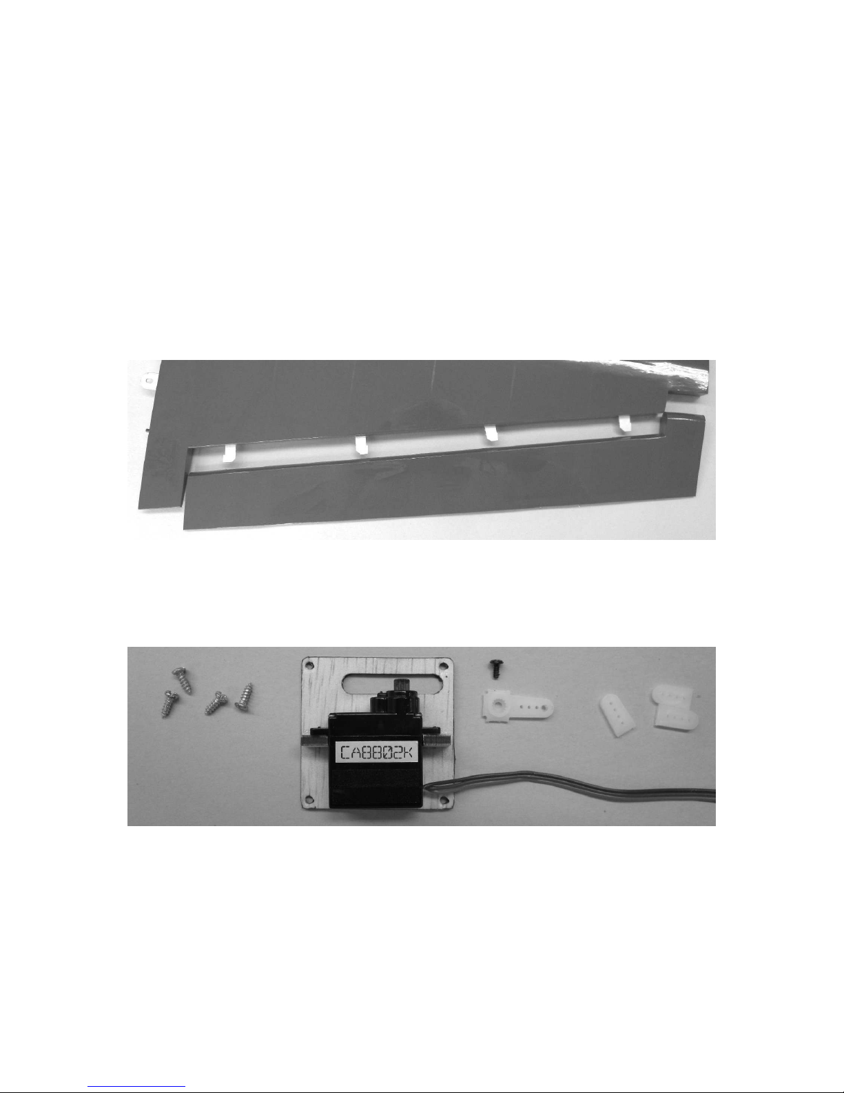
Unscrew the servo cover from the wing and fit in the servo. Separate the excess
levers and drill the outermost hole of the servo lever to Ø 1.6 mm. Put the servo into
the neutral position, attach the servo level vertically, and screw it tight. Use cyanoacrylate to glue the servo to the respective attachment tab.
Insert a string to pull the servo lead carefully into the wing. Screw on the servo cover
and make the aileron connection. Connect the pushrods and glue in the horn of the
aileron. Note: If you want to do extreme flight manoeuvres, you should use the longer
servo levers that are also included with the servo.

GRAUPNER GmbH & Co. KG D-73230 KIRCHHEIM/TECK GERMANY
Modifications reserved! No liability for printing errors! 10/2011
- 4 -
The figure shows the assembled aileron linkage. Please note that the servo level
length should be at least 12 mm to keep the clevis from colliding with the wing.
The figure shows the servo lead exiting at the wing root. Later, use the CRP tube Ø
8x280 mm to push the halves of the wing onto the fuselage.
Fuselage and tail group
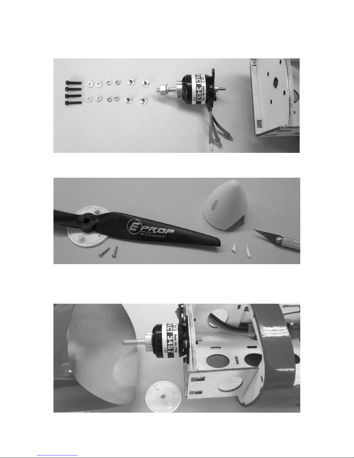
First place the motor spindle, motor mount, and locking ring onto the motor; these
parts are included as accessories in the package for Order No. 7738.
The figure shows the individual parts for the motor spindle and motor mount; tighten
all screws.
The figure shows the motor with attached motor mount and motor spindle. Separate
the motor leads and remove about 5 mm of insulation. Apply solder to the ends of all
leads and then solder on the G 3.5 connectors (included with Order No.7738).
Insulate the connector shaft with the heat-shrink sleeves (included with Order
No.7738) . Use a hair dryer to shrink the heat-shrink sleeve. Then do a test run of
GRAUPNER GmbH & Co. KG D-73230 KIRCHHEIM/TECK GERMANY
Modifications reserved! No liability for printing errors! 10/2011
- 5 -
the motor. Viewed in flight direction, the motor should rotate to the right; if this is not
the case, switch any two of the leads and re-insert.
Using the 4 M 3x10 mm and the washers and locking rings shown, screw the motor
in tight.
Place the GRP propeller spacer onto the propeller, enlarge the cut-outs in the spinner
cap to fit the propeller, separate the two short pins on the spinner back plate, so that
the spinner cap fits and can be pushed on without any stress.
 Loading...