

Page 1
GRAUPNER GmbH & Co. KG D-73230 KIRCHHEIM/TECK GERMANY
Modifications reserved. No liability for printing errors. 12/2011
Made in
Vietnam
1
Order No.
9357
Building Instructions
LANCAIR
For two-stroke engines up to around 10.63 cc capacity
and
electric power systems
This model requires a four-function radio control system
Page 2

GRAUPNER GmbH & Co. KG D-73230 KIRCHHEIM/TECK GERMANY
Modifications reserved. No liability for printing errors. 12/2011
Made in
Vietnam
2
Specification
Wingspan approx. 1700 mm
Fuselage length excl. spinner approx. 1330 mm
Wing area approx. 32 dm²
Tailplane area approx. 6.7 dm²
Total surface area approx. 38.7 dm²
All-up weight according to fittings approx. 3800 g
Longitudinal dihedral approx. 0,5 °
Centre of Gravity approx. 77 mm aft of leading edge
Sidethrust and downthrust built in as standard
Caution: this model is not a toy!
If you are a beginner to this type of powered model, please ask an experienced
model flyer for help and support. If you attempt to operate the aeroplane without
knowing what you are doing, you could easily injure yourself or somebody else.
Please keep your safety and well-being in mind at all times.
Important: before you start construction
Even if you have already built a large number of RC models please read right through
these instructions and check that all the kit components are actually present. We
have taken great trouble to keep construction as simple as possible, without making
any compromises in the area of safety.
Check that the radio control system is working correctly and at full range before every
flight: check that all the control surfaces work smoothly and immediately at an
appropriate distance, and deflect in the correct ‘sense’ (direction) relative to the stick
movements.
If you are a relative beginner to model flying, we recommend that you enlist the aid of
an experienced model pilot to help you check and test-fly the model.
The receiving system components and control linkages must be installed at the
appropriate stage of construction, as it may be very difficult or even impossible to install them later.
When you are buying a radio control system it is important to ensure that the transmitter and receiving system are designed for use with model aircraft, and are approved by your national Post Office approvals authority. All RC units should possess
an FTZ series approval number.
Please remember that other radio systems and radio-frequency apparatus are also
permitted to operate in the frequency ranges used by model radio control equipment,
and there is no guarantee that your system will not suffer interference caused by
such apparatus.
If you are not sure whether this applies to you, contact your nearest Post Office
Telecommunications office. Your local model shop will also have this information.
Note regarding the film covering
Minor creases or bubbles may develop in the film covering due to major fluctuations
in weather conditions (temperature, humidity etc.); in rare cases you may even find a
slight warp in a component. These minor faults are in the nature of film-covered builtup wooden structures, and can easily be corrected using a heat gun, as commonly
used for modelling.
Page 3
GRAUPNER GmbH & Co. KG D-73230 KIRCHHEIM/TECK GERMANY
Modifications reserved. No liability for printing errors. 12/2011
Made in
Vietnam
3
Creases: Blow warm air over the area and rub down with a soft cloth.
Wing warp: Hold the panel twisted gently in the opposite direction to the warp, and
apply warm air to remove the creases from the covering.
Caution! do not heat the film more than is absolutely necessary. If the air or the
iron is too hot, the film may melt and holes may be formed.
This aeroplane is highly pre-fabricated and can be built in a very short time.
However, the work which you have to carry out is important and must be done
carefully. The model will only be strong and fly well if you complete your tasks
competently - so please work slowly and accurately.
When self-tapping screws have to be screwed into wood, apply a little white
glue to prevent them shaking loose: just squirt white glue into the hole before
fitting the screw.
Additional items required
Glowplug engine
Engine
Order No.
Propeller
Order No.
OS MAX 65 AX
2771
33 x 18 cm
1318.33.18
Electric motor and accessories
Electric motor
Order No.
Propeller
Order No.
Flight battery
Order No.
Speed controller
Order No.
COMPACT
465 Z
7772
1318.36.20 9733.4 7224
Radio control system
The RC system must feature at least four channels and five servos. The transmitter should also include a servo reverse facility.
We particularly recommend MX-12 to mc-24 computer systems. Standard-sized servos are required for rudder, elevator and throttle.
For the ailerons the model needs servos with a case width of 13 mm.
We recommend the following receiver power supply: LiPo 2/1600, Order No. 9717.2,
in conjunction with the PRX 3A ON / OFF switch, Order No. 4135; these batteries
need to be maintained carefully before and after each flying session.
For more information please refer to the instructions supplied with your RC system,
rechargeable batteries, etc.
Page 4
GRAUPNER GmbH & Co. KG D-73230 KIRCHHEIM/TECK GERMANY
Modifications reserved. No liability for printing errors. 12/2011
Made in
Vietnam
4
For connecting the aileron servos to the receiver you will need two extension leads
180 mm and 320 mm long; foam rubber is also required for packing the receiver and
battery, e.g. foam rubber, Order No. 1637.
Adhesives
White glue, e.g. UHU coll, Order No. 958.60
UHU hart, e.g. Order No. 534.35
Cyano-acrylate (“cyano”), e.g. Order No. 5822
Thread-lock fluid, e.g. Order No. 952
Accessories required for the glow-engined version (not included)
Fuel based on synthetic oil, to suit engine
Fuel filter, e.g. Order No. 1650.1
Fuel tubing, e.g. Order No. 1643
Manual fuel pump, e.g. Order No. 1610
Glowplug energizer battery with plug clip, e.g. Order No. 3248
Electric starter, e.g. Order No. 1628
Starter battery, e.g. Order No. 2592
Accessories required for the electric-powered version (see table)
Battery chargers: see main FS catalogue
Tools required (not included)
Set of cross-point screwdrivers, flat-nose pliers, side-cutters, balsa knife or razor
blade, set of twist drills, universal glowplug spanner, soldering iron, set of allen keys.
Please don’t start assembling the model until you have checked the kit components
and the building instructions, and are familiar with the construction procedure. If you
are not happy with any component, kindly return it to your model shop without delay,
before you have modified it in any way.
Assembling the LANCAIR
The wing panels
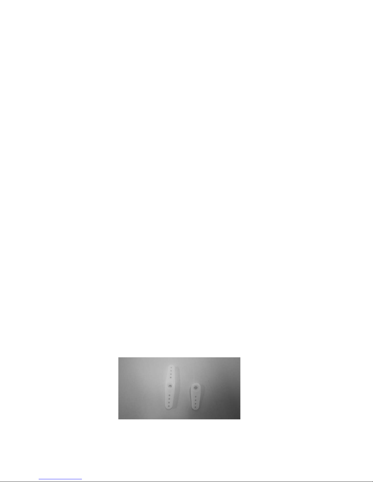
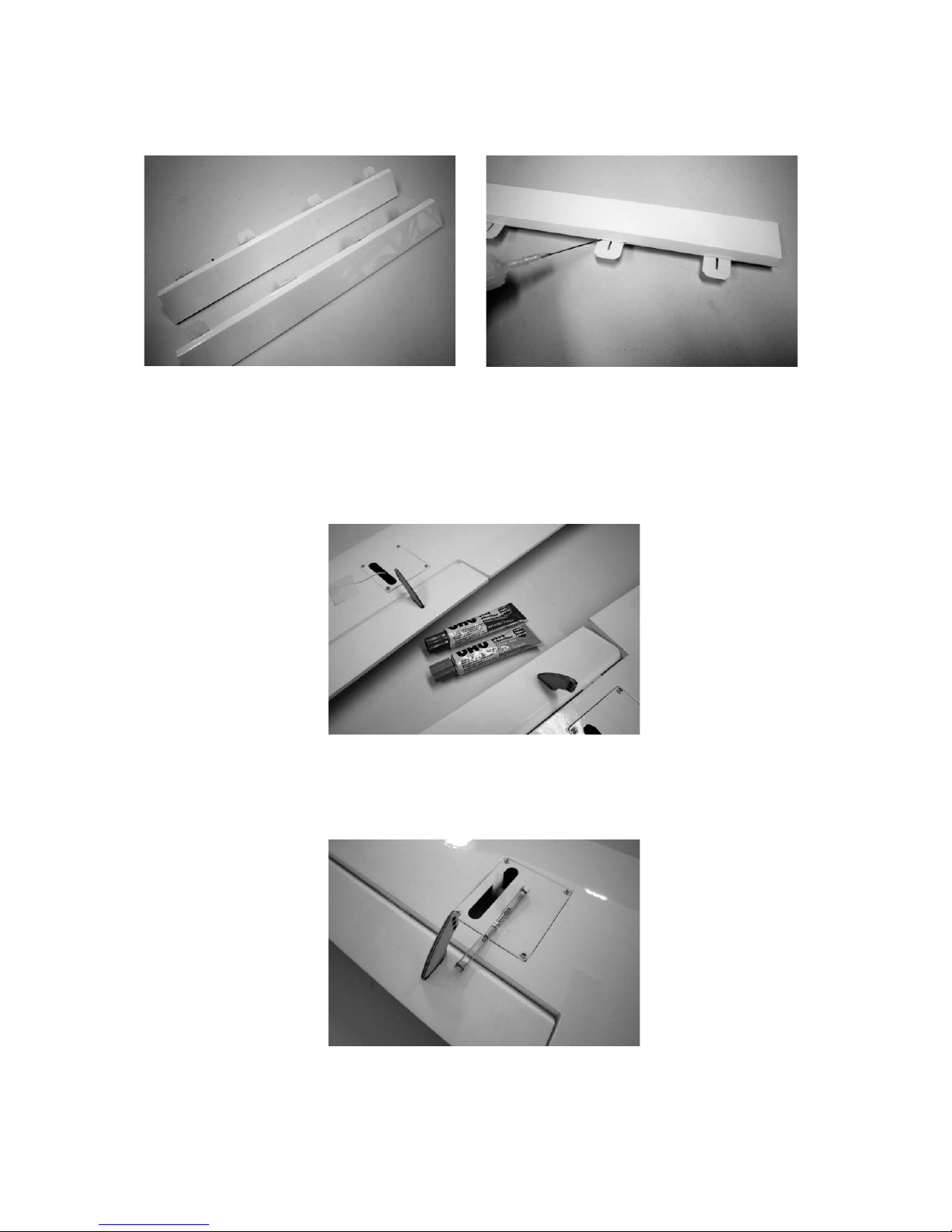
Remove one arm from the servo output levers, as shown in the photo. Set the servos
to centre from the transmitter, and fit the output levers on the servo output shafts.
Page 5
GRAUPNER GmbH & Co. KG D-73230 KIRCHHEIM/TECK GERMANY
Modifications reserved. No liability for printing errors. 12/2011
Made in
Vietnam
5
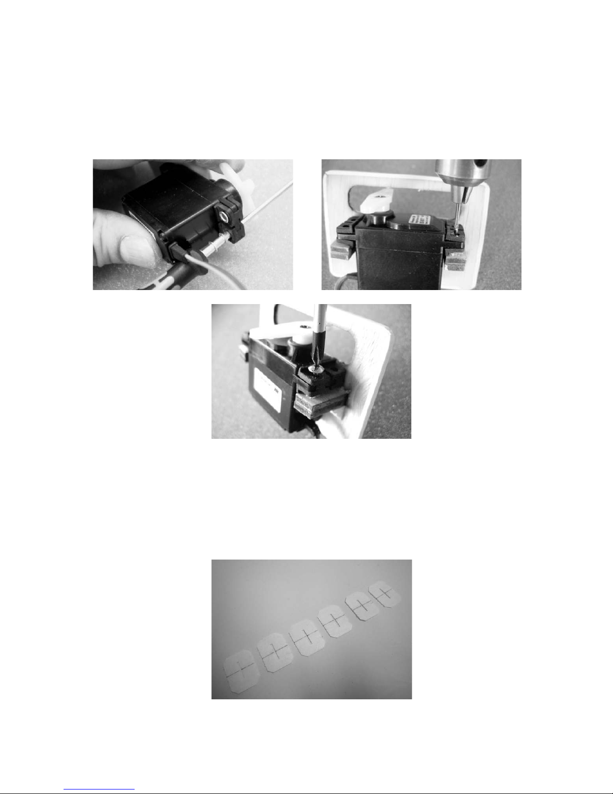
Set the servos to centre from the transmitter. The wing-mounted servos are attached
to the support blocks using the retaining screws supplied with them: the first step is to
push the rubber grommets into the servo mounting lugs, followed by the brass tubular
spacers, with the flange on the underside. The spacers are easier to fit if you slip
them on a suitable screwdriver first. Drill 1.5 mm Ø pilot-holes in the support blocks,
using the metal spacers as a guide, then fit the servo retaining screws as shown.
The servo leads can now be pulled through the wing panels using a length of thread:
tie the thread to the servo lead just behind the connector, then pull it through until it
appears at the root rib.
Fit the servo mounts in the wings and secure them with the retaining screws supplied.
Mark a centreline on all the aileron hinges using a pencil, as shown in the photo.
Page 6
GRAUPNER GmbH & Co. KG D-73230 KIRCHHEIM/TECK GERMANY
Modifications reserved. No liability for printing errors. 12/2011
Made in
Vietnam
6
The hinges can now be inserted in the ailerons as far as the pencil lines, and glued in
place using cyano; a syringe needle works well as a nozzle.
When the glue has set hard, insert the projecting hinges into the slots in the wings
and glue them in place with cyano. Note that there should be a gap about 0.5 mm
wide at the hinge line.
Shorten the GRP horns to the point where only the bottom linkage hole remains.
Use the tip of a hot soldering iron to remove the covering film over the horn slots, and
glue the horns in them using UHU plus (epoxy).
Ensure that the clevis linkage holes are exactly in line with the hinge pivot axis.
The aileron pushrods can be assembled when the glue has set hard. Adjust the
pushrod length so that the aileron is central when the servo is at neutral.
Page 7
GRAUPNER GmbH & Co. KG D-73230 KIRCHHEIM/TECK GERMANY
Modifications reserved. No liability for printing errors. 12/2011
Made in
Vietnam
7
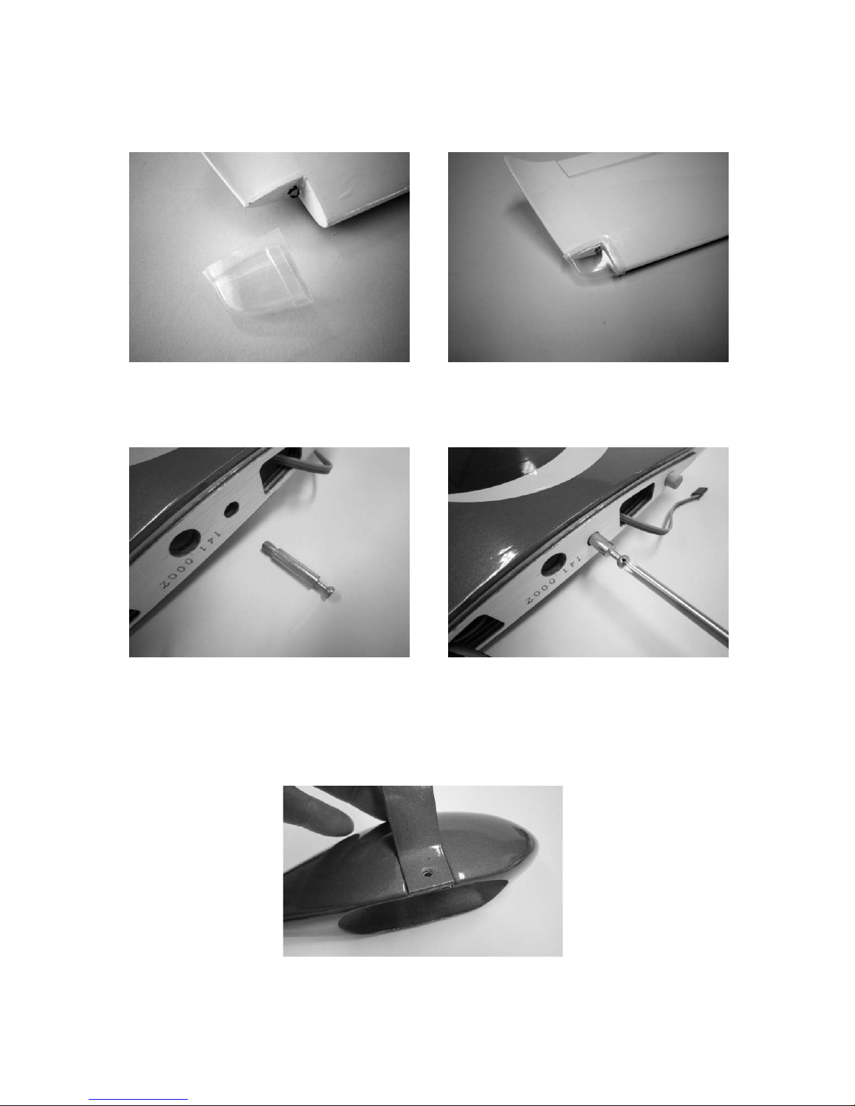
The two clear lamp covers can now be trimmed to size and glued to the wingtips.
Cyano or UHU ALLESKLEBER Kraft can be used as adhesive.
To hold the two wing panels against the fuselage a retaining bolt has to be screwed
into each wing root rib. Apply UHU thread-lock fluid to the threaded part, and screw
the bolts into the sockets as far as they will go.
Installing the undercarriage
Locate the screw-holes in the undercarriage legs and mark their position on the
wheel spats, as shown in the photo; you may need to chamfer the edges of the wheel
legs slightly so that they rest flush in the wheel spat recesses.
Page 8
GRAUPNER GmbH & Co. KG D-73230 KIRCHHEIM/TECK GERMANY
Modifications reserved. No liability for printing errors. 12/2011
Made in
Vietnam
8
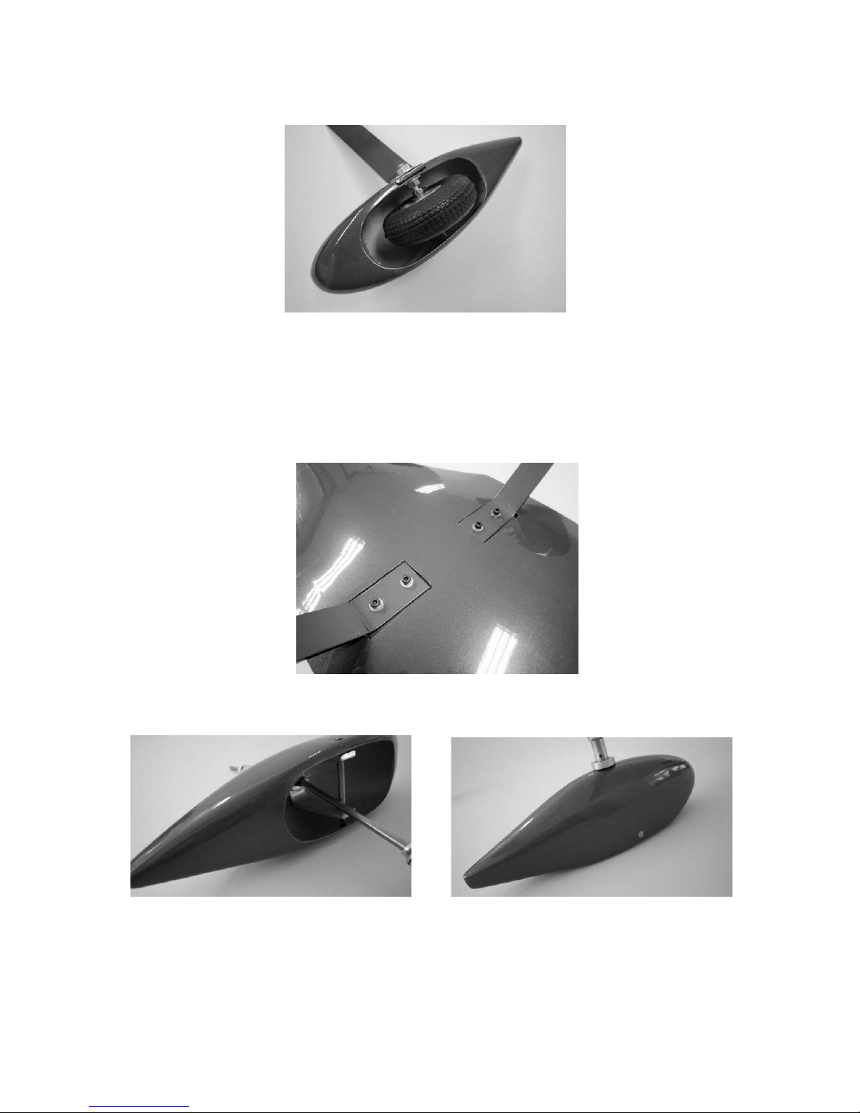
The wheels and the wheel axles can now be attached, as described below:
The first step is to fit the wheel and collets on the axle; the collets are used to centre
the wheels in the wheel spats. Apply a drop of UHU thread-lock fluid to the grubscrews and nuts to prevent them working loose.
Use the tip of a hot soldering iron to melt the film over the screw-holes and undercarriage mountings. Fix the undercarriage units to the fuselage using the socket-head
cap screws supplied in the accessory pack.
Prepare the noseleg yoke as shown in the photo: dismantle the yoke, then reassemble it with the wheel spat in the proper location.
The yoke must be aligned with the wheel spat before the socket-head cap screw is
finally tightened: this can be checked with a setsquare.
Page 9

GRAUPNER GmbH & Co. KG D-73230 KIRCHHEIM/TECK GERMANY
Modifications reserved. No liability for printing errors. 12/2011
Made in
Vietnam
9
Now mark the position of the axle holes in the wheel yoke on the wheel spat, and drill
the holes to match the diameter of the wheel axle. Install the wheel and the collets as
shown in the photo. The wheel axle should project by an equal amount on both sides
of the wheel spat.
The nosewheel unit can now be slid into the bearing hole in the noseleg bracket from
the underside, fitting the steering arm on it at the same time
To avoid having to dismantle the noseleg unit again, the steering pushrod should be
connected to the outer hole in the steering arm at this stage. Run the pushrod
through the guide tube, and glue the sleeve to the formers and other wooden parts.
Installing the tailplane and fin
Insert the hinges and horns in the appropriate slots in the tailplane and elevators, as
described for the ailerons, and glue them in place.
Page 10

GRAUPNER GmbH & Co. KG D-73230 KIRCHHEIM/TECK GERMANY
Modifications reserved. No liability for printing errors. 12/2011
Made in
Vietnam
10
When the glue has set hard, lay the tailplane on the saddle on the fuselage, and set it
exactly central; it must project by the same amount on both sides, and be square (at
right-angles) to the fuselage centreline.
Use a felt-tip pen to mark the outline of the fuselage on the underside of the tailplane.
Melt the covering film by running the tip of a hot soldering iron along the marked
lines, working just inside the lines. Take care not to use too powerful an iron; the heat
should be just sufficient to melt the film.
Carefully peel the covering film from the wood inside the marked lines.
The tailplane can now be glued to the fuselage using UHU coll or UHU hart. Position
the panel exactly as described at the start of this section. Pin or tape the tailplane in
place while the glue is drying, to prevent it shifting out of position.
Page 11

GRAUPNER GmbH & Co. KG D-73230 KIRCHHEIM/TECK GERMANY
Modifications reserved. No liability for printing errors. 12/2011
Made in
Vietnam
11
When the glue has set hard, place on the fin on the tailplane, fitting the bottom hinge
in the slot in the fuselage; the fin must rest squarely on the tailplane. In this position
mark the outline of the fin on the top of the tailplane using a felt-tip pen.
Melt the covering film using a soldering iron, as described previously, working just
inside the marked lines, and peel the unwanted film from the tailplane. The fin can
now be glued to the tailplane. Don’t forget to fit the bottom hinge in the slot in the
fuselage.
Tape the fin in place while the glue is setting, to prevent it shifting out of position.
As described in the first section, press the rubber grommets and metal tubular
spacers into the mounting lugs of the rudder and elevator servos, and screw the servos to the servo plate. Screw an M2 locknut and a clevis onto each end of the
threaded pushrods, and connect the clevises to the horns and the servo output arms.
Set the servos to centre, and check that the rudder and elevator are also central; if
not, screw the clevises in or out to correct.
The photo shows how a swivel pushrod connector is fitted to the nosewheel steering
linkage. Tighten the locknut on the connector barrel just to the point where the barrel
rotates smoothly, but without noticeable slop. Adjust the system so that the
nosewheel is at centre when the rudder is also at neutral, then clamp the nosewheel
steering pushrod in the pushrod connector. This should ensure that the model will roll
in a straight line on the ground.
Page 12

GRAUPNER GmbH & Co. KG D-73230 KIRCHHEIM/TECK GERMANY
Modifications reserved. No liability for printing errors. 12/2011
Made in
Vietnam
12
Install the throttle servo in the servo plate as shown in the photo. Fit a swivel pushrod
connector in the servo output arm (lever length 11 mm), checking that the connector
rotates smoothly, without lost motion.
Assembling and installing the fueltank
Cut a piece of fuel tubing and push it onto the fueltank clunk pick-up. Push the free
end of the fuel tubing onto one of the tubes in the fueltank stopper, and check that
the pick-up will be able to move freely inside the tank when the stopper is in place,
without binding or jamming. Fit two more pieces of fuel tubing on the two free tubes
for filling the tank and to act as the overflow; the one should end at the top of the
fueltank, the other at the bottom; this ensures that the tank can be completely filled
and completely emptied when required. Now push the tank stopper, complete with
pick-up and pre-formed tubes, into the throat of the fueltank, as shown in the picture;
ensure that one tube faces down (for filling the tank). The tube pointing up acts as
overflow when refuelling, and will later be connected to the pressure nipple on the
silencer. At this point the three fuel lines should be marked with a felt-tip pen or
adhesive tape to identify them (carburettor, filler, pressure). Push the stopper over
the throat of the tank and tighten the cross-point screw to clamp it in place. It is
essential to tighten the screw to the point where the tank is completely sealed.
The completed fueltank can now be fitted inside the fuselage, routing the fuel lines
through the hole in the firewall. Glue the two formers in the fuselage to prevent the
tank shifting, as shown in the photo.
Page 13

GRAUPNER GmbH & Co. KG D-73230 KIRCHHEIM/TECK GERMANY
Modifications reserved. No liability for printing errors. 12/2011
Made in
Vietnam
13
Connecting the fuel lines
Connect the silicone fuel tube from the fuel pick-up to the carburettor nipple, and the
overflow tube to the silencer pressure nipple.
For refuelling, route the fuel line marked as the filler tube out of the cowl, secure it,
and then seal it again when the tank is full, using a sealing nipple, Order No. 140.
When the tank is full, ensure that the silencer is not filled with fuel via the overflow,
which acts as pressure connection.
Installing the glowplug engine
The bottom of the fuselage has to be cut away at the appropriate point to clear the
silencer (silencer duct): slit the covering film as shown in the photo, and peel it back
from the underlying wood.
The wood under the film can now be cut away to clear the silencer. Iron the flaps of
film down on the inside of the duct. The glow engine, complete with silencer, can now
be installed.
Attach the two-part engine mount to the firewall using the screws provided with it.
Screw the engine to the motor mount in such a way that the distance between the
front face of the firewall and the front of the propeller driver is about 142 mm. Note
that the engine downthrust must not be altered, i.e. the prop driver should lie parallel
to the firewall. The easy way to check this is to place the spinner backplate on the engine’s crankshaft.
Page 14

GRAUPNER GmbH & Co. KG D-73230 KIRCHHEIM/TECK GERMANY
Modifications reserved. No liability for printing errors. 12/2011
Made in
Vietnam
14
Before the cowl can be fitted, it must be cut away to clear projecting parts such as the
silencer, carburettor, noseleg, needle valve, etc. File all openings to a smooth, neat
shape.
Cut all openings undersize at first, then slowly open them up to final shape.
The cowl can now be fitted on the fuselage, followed by the spinner. Make it a regular
routine matter to check that the propeller retaining nut is tight.
The cowl is fixed to the fuselage using four pan-head self-tapping screws.
Page 15

GRAUPNER GmbH & Co. KG D-73230 KIRCHHEIM/TECK GERMANY
Modifications reserved. No liability for printing errors. 12/2011
Made in
Vietnam
15
Installing the electric motor
Mark the position of the mounting holes for the electric motor, and drill the holes to
suit the screws / captive nuts.
The motor mount for the electric motor is installed using the same screws and nuts
intended for the glowplug engine.
Screw the motor mount to the firewall, and the electric motor to the motor mount.
Glue triangular fillets to the corner joints of the motor mount to reinforce them.
An additional plywood plate has to be installed in the fuselage to act as support for
the flight battery and the speed controller; the flight pack and the controller are fixed
to the plate using Velcro (hook-and-loop) tape straps.
Page 16

GRAUPNER GmbH & Co. KG D-73230 KIRCHHEIM/TECK GERMANY
Modifications reserved. No liability for printing errors. 12/2011
Made in
Vietnam
16
When connecting the speed controller it is important to check that polarity is correct,
i.e. that the motor rotates in the appropriate direction. Refer to the instructions supplied with the speed controller and the motor for more information.
Installing the switch in the fuselage
The ON / OFF switch for the RC system (PRX 3A) can be installed in either fuselage
side (right or left). Use the tip of a hot soldering iron to melt the film over the openings
for the switch slider and the LED. The switch can then be installed in the fuselage
side using the retaining screws supplied with the unit.
The canopy
Glue the dummy pilot and the seat backrest to the cabin frame as shown in the photo
(Stabilit Express).
When the glue has set hard, attach the canopy to the frame using the six pan-head
self-tapping screws supplied in the accessory pack.
Page 17

GRAUPNER GmbH & Co. KG D-73230 KIRCHHEIM/TECK GERMANY
Modifications reserved. No liability for printing errors. 12/2011
Made in
Vietnam
17
It is also a good idea to apply a strip of clear adhesive tape to the underside of the
canopy on both sides.
Connecting the wingtip lighting system
Solder BEC leads, Order No. 3029, to the leads which project from the root ribs.
Each soldered joint must be insulated with a heat-shrink sleeve. Glue an ON / OFF
switch, Order No. 3934.4, to the former inside the fuselage. Solder (or otherwise
connect) one lead from the switch to the battery box supplied in the set, and solder
the cables from the wings to the other side of the switch.
Assembling the LANCAIR
It is advisable to connect two short extension leads, Order No. 3935.18, to receiver
output sockets 2 and 5, as this makes it easier to connect the aileron servo leads
from the wings when the model is rigged. Pack the receiver battery in foam, and
secure it carefully in the fuselage, so that there is no chance of it shifting in flight.
Plug the wing panels into the fuselage using the joiner tube, and plug the two aileron
servos into the extension leads already connected to the receiver. Push the wings up
against the fuselage, and rotate the retainers to fix the panels in place.
The servo leads and the wingtip lighting leads can now be connected.
Page 18

GRAUPNER GmbH & Co. KG D-73230 KIRCHHEIM/TECK GERMANY
Modifications reserved. No liability for printing errors. 12/2011
Made in
Vietnam
18
Place the canopy in the recess in the fuselage with the two front lugs engaged in the
notches in the former. The canopy is fixed to the fuselage using two plastic screws.
Take care not to over-tighten these screws; tighten them just to the point where the
canopy cannot shift on the fuselage.
Balancing the LANCAIR
Support the model under the wing roots on both sides of the fuselage at a point about
77 mm aft of the root leading edge*. If the Centre of Gravity is correct, the model will
now balance level, ideally with the nose pointing slightly down.
If necessary, adjust the position of the battery or install lead ballast until the CG is at
the stated point.
Before flying the aircraft, set the transmitter trims to centre and ensure that all the
control surfaces are also exactly at centre (neutral).
Control surface travels
Ailerons 15 mm up, 12 mm down )
Elevator 10 mm up, 10 mm down ) 30% Exponential
Rudder 30 mm right, 30 mm left )
Please note that the control surface travels are only a recommended starting point you will probably need to adjust them to suit your personal flying style.
Important:
When fitting and adjusting the various linkages you should ensure that they move
freely, without binding, are able to move to their full extent - including trim travel - and
are not obstructed mechanically at any point.
When you move the rudder stick to the right, the rudder should also deflect to the
right (left stick: left rudder). Pull the elevator stick back towards you, and both
elevators must deflect up (stick forward: elevator down). If you move the aileron stick
to the right, the right aileron should rise, the left aileron fall. When you move the
throttle stick forward, the engine (or electric motor) should run at full power; pull the
throttle stick back, and the engine should idle (or stop). Move the trim right back to its
end-point, and the engine should reliably stop.
All that remains is for us to wish you many hours of pleasure flying your LANCAIR.
*best in inverted flight
Page 19

GRAUPNER GmbH & Co. KG D-73230 KIRCHHEIM/TECK GERMANY
Modifications reserved. No liability for printing errors. 12/2011
Made in
Vietnam
19
Safety notes and warnings relating to model aircraft powered by
internal-combustion engines
Be sure to read right through the instructions covering assembly and operation
of your model before you attempt to operate it for the first time.
These safety notes are an integral part of the instructions. Please keep them
and the operating instructions in a safe place. If you ever dispose of the model
be sure to pass them on to the new owner.
Powered model aircraft are very demanding and potentially dangerous
machines, and call for a high level of technical knowledge and skill from the
operator, together with a responsible attitude.
Powered model aircraft are not suitable for young persons under eighteen
years of age.
Young people should only be permitted to operate this model under the
instruction and supervision of an adult who is aware of the hazards involved in
this activity.
The operator of the model must be in full possession of his bodily and mental
faculties. As with car driving, operating a model aircraft under the influence of
alcohol or drugs is not permissible under any circumstances.
Radio-controlled model aircraft may only be employed for the purpose
intended by the manufacturer. They must never be used as man-carrying
machines. Any other use of this model is prohibited.
A radio-controlled model aircraft can only work properly and fulfil your
expectations if it is built very carefully and in accordance with the building
instructions. Do not make any modifications of any kind to the design features
or materials. If you wish to avoid injuring people and damaging property it is
essential to be careful and painstaking at all stages of building and operating
your model. Nobody would climb into a full-size light aircraft and try to fly it
without completing a course of training first. Model flying is a skill which has to
be learned in just the same way. We suggest that you ask for help from an
experienced model flyer, or join a model club or flight training school. Your
local model shop and the specialist magazines are excellent sources of
information.
It is fundamentally essential to set the Centre of Gravity (C.G.) and control
surface travels correctly. Adjust the model until they are exactly correct.
• Radio control system: satisfy yourself that your frequency is vacant before
you switch on. Check your RC system regularly as its components
eventually wear and need to be replaced or repaired. Radio interference
caused by unknown sources can occur at any time without warning. If this
should happen, your model will be uncontrollable and completely
Page 20

GRAUPNER GmbH & Co. KG D-73230 KIRCHHEIM/TECK GERMANY
Modifications reserved. No liability for printing errors. 12/2011
Made in
Vietnam
20
unpredictable. Never leave your radio control system unguarded, as other
people might pick it up and try to use it. Your RC system can only work
reliably if the batteries are kept fully charged.
Don’t ignore our warnings. They refer to materials and situations which, if
ignored, can result in fatal injury or permanent damage.
You alone are responsible for the safe operation of your radio-controlled model
aircraft and engine.
If you have any questions regarding the safe operation of your RC model
aircraft, please turn to your local model shop in the first instance as the staff
will be pleased to help you.
• Propellers and other rotating parts which are powered by an engine
represent a permanent hazard and present a real risk of injury. Don’t touch
them with any part of your body. For example, a propeller spinning at high
speed can easily slice off a finger.
• Keep clear of the rotational plane of the propeller. You never know when
some part may come loose and fly off at high speed, hitting you or anybody
else in the vicinity. Never touch the spinning propeller with any object.
• Take care with loose clothing such as scarves, loose shirts etc. Flapping
cloth can easily be sucked into the area of the propeller and then get
tangled in the blades. This is extremely dangerous.
• If there are passers-by or spectators at your flying site, make sure that they
are aware of the dangers inherent in your activity, and insist that they keep
a safe distance away (at least 5 m).
• Radio-controlled models should only be flown in “normal” weather
conditions, i.e. a temperature range of -5° to +35° C. More extreme
temperatures can lead to changes in battery capacity, material
characteristics and other unwanted effects.
• Model fuels are toxic; do not allow them to come into contact with your
eyes or mouth. Fuel should always be stored in clearly marked containers,
out of the reach of children.
• Never run an internal combustion engine in an enclosed space such as a
cellar, garage etc. Model engines produce lethal carbon monoxide gas just
like full-size engines.
Engines should only be run in the open air!
• Adhesives and paints contain solvents which may be hazardous to health
under certain circumstances. Read and observe the notes and warnings
supplied by the manufacturer of these materials.
Page 21

GRAUPNER GmbH & Co. KG D-73230 KIRCHHEIM/TECK GERMANY
Modifications reserved. No liability for printing errors. 12/2011
Made in
Vietnam
21
• Model fuels are volatile and highly inflammable. Keep them well away from
open flames, excessive heat, all possible sources of sparks and anything
else which could result in a fire. Do not smoke in the immediate vicinity of
fuel or fuel vapours.
• Model engines generate a lot of heat. The engine and silencer in particular
become very hot when running, and stay at a high temperature for quite a
while. Touching the hot parts can give you serious burns, so take care
especially when carrying out adjustments - wear protective gloves. Hot
engines can even start a fire under certain circumstances.
• When the engine is running it expels hot toxic gases from the exhaust
together with very hot fluid combustion residues which can burn you if you
are not careful.
• Remove all unused fuel from the fueltank and engine after every session.
• Every time you intend to operate your model check carefully that it and
everything attached to it (e.g. propeller, linkages, control surfaces etc.) is in
good condition and undamaged. If you find a fault, do not fly the model
until you have corrected it.
• Model engines are usually started with the help of an electric starter which
should be fitted with the appropriate adaptor where necessary. With fixedwing models an alternative is to use a “chicken stick” - a length of thick
wooden dowel with a piece of water hose pushed over it
• Many model engines are very noisy, producing a sound level much higher
than 85 dB (A-weighted), which implies that you should wear ear defenders.
Never run a engine without the silencer fitted. Even with a silencer, model
engines can easily disturb your neighbours. Don’t run engines when other
people expect peace and quiet.
• If you start your engine when the model is standing on loose or sandy
ground, the propeller will suck up sand and dust and hurl it around, and it
could easily get in your eyes and do damage. Wear protective goggles at
such times.
• Take care that the glowplug clip and the lead cannot get tangled in the
propeller or other rotating parts. Check the throttle linkage too.
• Take particular care when carrying the model with the engine running. Hold
the rotating parts well away from you!
• Be sure to keep an adequate supply of fuel in the tank. Don’t continue to fly
the model until the tank is drained dry.
Page 22

GRAUPNER GmbH & Co. KG D-73230 KIRCHHEIM/TECK GERMANY
Modifications reserved. No liability for printing errors. 12/2011
Made in
Vietnam
22
• Never fly directly over people.
• Never fly directly towards people.
• Keep a safe distance from residential areas: at least 1.5 km ‘as the crow
flies’. The best solution is to join a model flying club and use the approved
flying site. Always keep well clear of high-tension overhead cables.
• Whenever you are working on the engine, make sure that you are on a safe
surface and cannot slip. Get used to holding the model really securely.
• Take-off and landing strips should be kept free of unauthorised people and
movable obstacles, particularly when a model is using the strip.
• Watch the aeroplane constantly while it is in the air. Models must always
give way to full-size aircraft.
• Don’t operate your aircraft from public roads, squares, school playgrounds,
public parks or sports grounds etc., and ensure that you are always in full
control of the model.
• It is important that you are able to stop your engine at any time. This is
achieved by adjusting the throttle so that the barrel closes completely
when you move the throttle stick and trim to their end-points. If this does
not work, pinch the fuel feed line between your fingers or pull it off the
carburettor. Never try to stop the engine by grasping the flywheel, propeller
or spinner!
• All model flyers should behave in a manner which minimises the danger to
people and property. Never act in any way which will disturb other flyers
and jeopardise safe, orderly flying at the site.
In legal terms our models are classed as aircraft, and as such are subject to
legal regulations and restrictions which must be observed.
Our brochure “Modellflugrecht, Paragrafen und mehr” (Model Aviation Law,
Legal Requirements and more) is available under Order No. 8034.02, and
contains a summary of all these rules. Your local model shop should have a
copy which you can read. Models fitted with glowplug engines may only be
flown with the landowner’s permission, and third party insurance is mandatory.
There are also Post Office regulations concerning your radio control system,
and these must be observed at all times.
Please don’t misunderstand the purpose of these notes. We only want to make
you aware of the many dangers and hazards which can arise if you lack
knowledge and experience, or work carelessly or irresponsibly. If you take
reasonable care, model flying is a highly creative, instructive, enjoyable and
relaxing pastime.
Page 23

GRAUPNER GmbH & Co. KG D-73230 KIRCHHEIM/TECK GERMANY
Modifications reserved. No liability for printing errors. 12/2011
Made in
Vietnam
23
Important Safety Notes
You have acquired a kit which can be assembled into a fully working RC model
when fitted out with suitable accessories. However, we as manufacturers have
no control over the way you build and operate your RC model aircraft, nor how
you install, operate and maintain the associated components, and for this
reason we are obliged to deny all liability for loss, damage or costs which are
incurred due to the incorrect use of our products or due to incompetent
behaviour on the part of the user, or which are connected with such operation
in any way. Unless otherwise prescribed by binding law, the obligation of the
GRAUPNER company to pay compensation, regardless of the legal argument
employed, is excluded. This includes personal injury, death, damage to
buildings, damages due to loss of business or turnover, interruption of
business or other direct or indirect consequent damage whose root cause was
the operation of the model.
The total liability in all cases and under all circumstances is limited to the
amount of money which you actually paid for the model.
This model is built and flown at the sole and express responsibility of the
operator. The only way to avoid injury to persons and damage to property is to
handle and operate the model with the greatest care and consideration at all
times.
If you have not already done so, it is essential to take out a special third-party
insurance policy to cover the risks involved in model flying.
These safety notes must be kept in a safe place. If you ever dispose of the
model, be sure to pass them on to the new owner.
Guarantee Conditions
The guarantee provides for the replacement of any part or parts which exhibit proven
manufacturing faults or material defects within the guarantee period of 24 months
from the initial date of purchase. We will not entertain any claims which fall outside
these restrictions. Costs of transport, packaging, freight and travel are payable by the
purchaser. We accept no liability for transport damage. The product should be sent to
GRAUPNER or to the approved Service Centre in your own country, together with an
accurate, concise description of the fault and the invoice showing the purchase date.
The guarantee does not cover damage to or failure of the product or model caused
by an accident, incompetent handling or incorrect use.
Page 24

GRAUPNER GmbH & Co. KG D-73230 KIRCHHEIM/TECK GERMANY
Modifications reserved. No liability for printing errors. 12/2011
Made in
Vietnam
24
The following points are important and must be observed at all times:
• Before you fly the model, check that the radio control system is working
reliably, and that all connections are secure.
• The batteries must be charged and the range of the radio control system must
be checked before you operate the model. In particular, the radio control
system batteries must be charged before each session and checked before
every flight.
• Ensure that the channel you intend to use is not already in use by other
modellers. Never fly the model if you are not certain that your channel is free.
• Read and observe the instructions and recommendations provided by the
manufacturer of your radio control system and accessory components.
• Ensure that the servos are not mechanically obstructed at any point in their
travel.
• Dry cells and rechargeable batteries must never be short-circuited.
• Remove all batteries from the model prior to transporting and storing it.
• Do not subject the model to dirty or cold conditions, or high levels of humidity
or heat.
• Secure the model and your RC equipment carefully when transporting them.
They may be seriously damaged if they are free to slide about.
Care and maintenance
• Clean the model carefully after every flight, and remove any dirt from the
propeller. Clean the aeroplane and the RC components using suitable
cleaning agents only. Ask your model shop for information if you are not sure.
• If the model is not to be operated for a considerable time it is important to
clean and re-lubricate all the moving parts.
Notes on building the model
• Before you start building the aircraft it is essential to study the plan and read
right through the instructions. Please bear in mind the dangers inherent in the
handling of tools.
• When preparing wiring, be sure to use cable capable of carrying the currents
likely to flow when the model is flying.
• Remove all traces of grease from the joint surfaces of components which are
to be glued. A good method is to sand lightly before wiping with a non-greasy
liquid detergent solution. The same applies to surfaces which are to be
painted, otherwise the paint will not adhere permanently. Before gluing any
GRP parts, and GRP fuselages in particular, the joint surfaces must be
sanded thoroughly with fine-grit abrasive paper before de-greasing with a
solvent such as acetone. This is the only method of obtaining durable glued
joints involving GRP parts.
 Loading...