

Page 1
GRAUPNER GmbH & Co. KG D-73230 KIRCHHEIM/TECK GERMANY
Modifications reserved. No liability for printing errors. Id. No. 0062316 10/2011
1
Order No. 4565.HOTT
OPERATING INSTRUCTIONS
ELEKTRO
ELEKTRO ELEKTRO
ELEKTRO ---- JUNIOR
JUNIOR JUNIOR
JUNIOR PLUS
PLUS PLUS
PLUS SSSS
Ready-to-fly RC model fitted with HPD 3515 motor set,
three 1600 mAh LiPo cells and HoTT receiving system.
This model requires a HoTT COMPUTER SYSTEM
Page 2

GRAUPNER GmbH & Co. KG D-73230 KIRCHHEIM/TECK GERMANY
Modifications reserved. No liability for printing errors. Id. No. 0062316 10/2011
2
Please be sure to read through the safety notes in the Appendix to these operating instructions. If you ever dispose of the model, it is important to pass on these safety notes and the
complete building instructions to the new owner.
Introduction
The ELEKTRO JUNIOR PLUS S is an elegant electric-powered model aircraft which
offers particularly docile flying characteristics combined with an outstanding performance in the air. The aeroplane is supplied virtually ready to fly, but some experience
of model flying is required if it is to be operated successfully. The aeroplane and the
HPD high-performance motor system are carefully optimised for the 3S / 1600 mAh
LiPo battery supplied in the set: the model is capable of a vertical climb at a
moderate current drain of around 30 A. The aircraft can be stored and transported
safely and conveniently in the packaging carton.
Pack contents
1. Fuselage with factory-installed HPD motor set, including CAM FOLDING PROP,
pre-fitted C 261 rudder and elevator servos, Graupner GR-12 HoTT receiver and
CARBON-LOOK canopy
2. Pair of wings with factory-fitted C 261 aileron servos
3. CFRP wing spar, 10 / 8 Ø x 1000 mm
4. Tailplane with elevator horn
5. LiPo flight battery, 3/1600 11.1 V / 1.6 Ah, Order No. 7634.3, including safety
notes
6. 4565.HOTT operating instructions in German, English and French
Essential accessories (not included)
GRAUPNER HoTT COMPUTER SYSTEM transmitter min. MX 12 to MC 32
Transmitter charge lead Order No. 3022
Battery charge lead with G3.5 connector Order No. 2970.L
ULTRAMAT 16 S battery charger Order No. 6468
Tools required to assemble the model (not included)
Cross-point screwdriver
Operating instructions
Please start by reading right through these operating instructions, and make yourself
familiar with the method of operating your HoTT transmitter. Keep the manual for
your HoTT COMPUTER SYSTEM to hand when preparing the model. When you are
setting up the transmitter with the LiPo battery and the speed controller connected
(G3.5 plugs / sockets), it is particularly important to avoid the folding propeller fitted to
the motor coming into contact with any part of your body. Any error or carelessness
Page 3
GRAUPNER GmbH & Co. KG D-73230 KIRCHHEIM/TECK GERMANY
Modifications reserved. No liability for printing errors. Id. No. 0062316 10/2011
3
when the battery is connected might cause the motor to burst into life unexpectedly,
and this could result in serious injury.
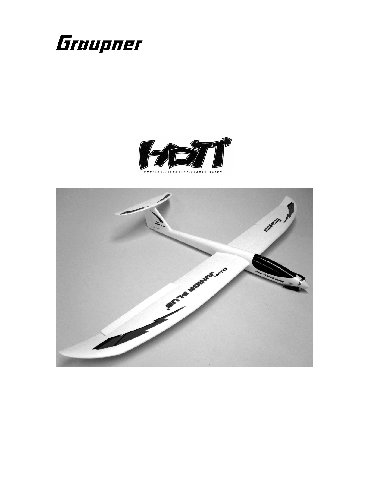
Assembling the model
Connect the elevator horn as shown in the pictures, then fix the tailplane to the top of
the fin using the M4 x 25 mm countersunk screw (shown already fitted in the photo).
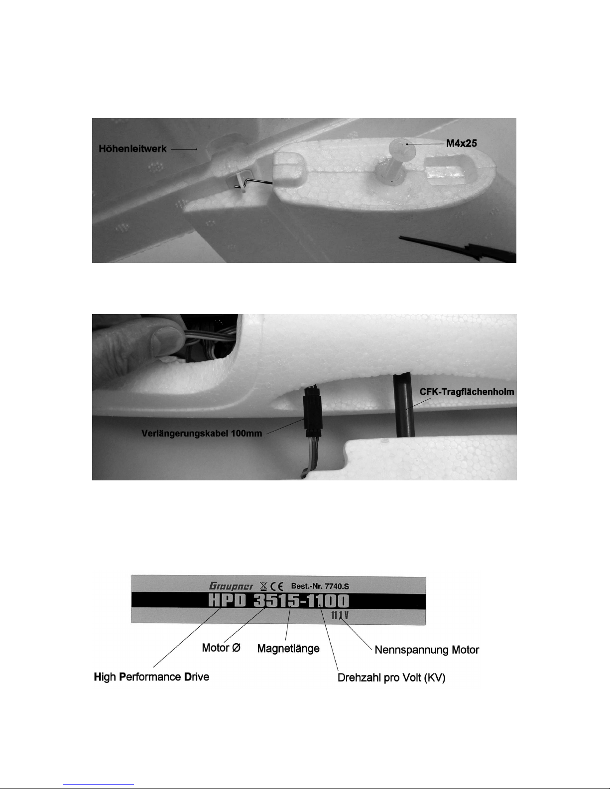
The wing panels are assembled and fitted as shown in the illustration above: first fit
the wings together using the CFRP spar, then connect the 100 mm servo extension
leads. Push the wings together, at the same time carefully drawing the extension
leads forward towards the receiver.
The HPD motor set
Page 4
GRAUPNER GmbH & Co. KG D-73230 KIRCHHEIM/TECK GERMANY
Modifications reserved. No liability for printing errors. Id. No. 0062316 10/2011
4
The high-quality HPD motor set is supplied already installed in the fuselage. The
picture above shows the type designation of the brushless motor. The matching
speed controller is set up accurately at the factory to suit the ELEKTRO-JUNIOR
PLUS S, eliminating the need for programming, but the Appendix includes additional
information on the speed controller’s set-up facilities and possible applications.
Binding the GR-12 receiver to your HoTT transmitter
This procedure varies according to the HoTT COMPUTER SYSTEM you are using;
please read the manual supplied with your RC system for details. For safety reasons
we recommend that all adjustments are made using a separate receiver battery (e.g.
Order No. 2585) instead of connecting the LiPo flight pack. Connect the receiver
battery to receiver socket 6 instead of the speed controller.
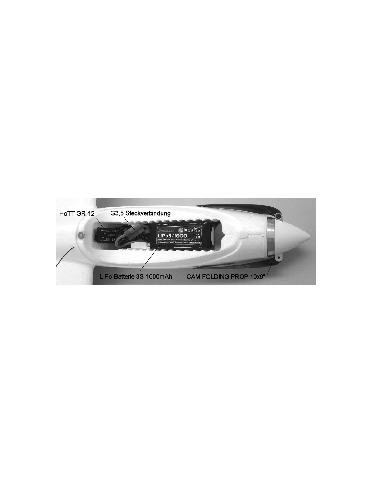
Installing the HoTT receiver and the LiPo battery
The servo leads can now be connected to the receiver. The socket sequence is as
follows: socket 2: left aileron servo; socket 3: elevator servo; socket 4: rudder servo;
socket 5: right aileron servo; socket 6: speed controller. The 100 mm servo extension
leads are connected to receiver sockets 2 and 5 while the wing is assembled and
fitted. Check all the working systems from the radio control system transmitter.
The photo above shows the HoTT receiver connected to the other receiving system
components, and the completed G3.5 connection between speed controller and LiPo
battery. Before connecting the G3.5 plugs and sockets ensure that the motor switch
or stick at the transmitter is in the “OFF” position. Bear in mind that the motor may
burst into life when the G3.5 plugs and sockets are connected, so keep well clear of
the propeller. Always carry out test-runs in the open air. It is helpful to have an
assistant to hold the model securely for you while you are operating the transmitter.
Control surface travels
We recommend the following maximum travels, in each case measured at the trailing
edge of the control surface: ailerons 25 mm up, 12 mm down; elevator 8 mm up, 8
mm down; rudder 25 mm to either side of neutral. The correct travels can be set at
the transmitter; please refer to the manual supplied with your HoTT COMPUTER
SYSTEM for information on this process.
Balancing
Assemble the model completely, ready to fly.
Page 5

GRAUPNER GmbH & Co. KG D-73230 KIRCHHEIM/TECK GERMANY
Modifications reserved. No liability for printing errors. Id. No. 0062316 10/2011
5
The Centre of Gravity range is 60 to 70 mm aft of the wing root leading edge; this can
be achieved by adjusting the position of the LiPo flight battery. Support the model at
the stated CG position with two fingers under the wing roots, and allow it to hang
freely: the fuselage will remain level when balanced correctly.
Flying
Wait for a day with little or no breeze for the initial test-flight. The ideal flying site is a
grassy field with a gentle slope facing into wind. Assemble the model completely, and
check that the control surfaces are exactly at centre before flying.
Switch the motor on and give the aeroplane a hand-launch exactly into any
breeze; trotting forward for a few steps gains the necessary momentum. Initially
use the ailerons and elevator very gently just to correct any deviations from a straight
flight path. Fine-tuning can be carried out by adjusting the trim sliders or buttons
situated below and adjacent to the transmitter sticks. If the model is balanced at the
forward end of the stated CG range, you will need to set about 1 mm of up-trim.
Always land the model directly into wind, with the motor switched off. You can effectively shorten the model’s landing approach by deploying the airbrake function
(both ailerons deflected up). Just before touch-down, apply slight up-elevator to flare
out and slow the machine down further. Always land directly into wind.
All of us at GRAUPNER Modellbau wish you many fine flights with your new
ELEKTRO-JUNIOR PLUS S
Adhesives for possible repairs to the SOLIDPOR® components (not included)
Cyano-acrylate (“cyano”) Order No. 5821
Cyano activator Order No. 953.150
Replacement parts (not included)
Canopy Order No. 4527.1
Fuselage shells Order No. 4527.2
Wing panels Order No. 4527.3
Tailplane Order No. 4527.4
Small ABS parts Order No. 4527.5
Decal sheet Order No. 4565.14
Countersunk nylon screws, M4 x 25 Order No. 5891.25
CFRP wing spar Order No. 5221.10.8
HPD 3515-1100 motor set Order No. 7740.S
50 mm Ø precision spinner Order No. 6050.4
Propeller blades, 25 x 15 cm * Order No. 1336.25.15
* The M3 x 13 propeller blade retaining screws used on the folding propeller are secured at the factory with thread-lock fluid. If
you need to replace the retaining screws, be sure to use UHU thread-lock fluid, Order No. 952, to secure the new ones.
Page 6

GRAUPNER GmbH & Co. KG D-73230 KIRCHHEIM/TECK GERMANY
Modifications reserved. No liability for printing errors. Id. No. 0062316 10/2011
6
Environmental protection notes
The presence of this symbol on a product, in the user instructions or the packaging, means that you must not dispose of that item, or the electronic
components contained within it, in the ordinary domestic waste when the product comes to the end of its useful life. The correct method of disposal is to
take it to your local collection point for recycling electrical and electronic equipment.
Individual markings indicate which materials can be recycled and re-used. You can make an important contribution to the protection of our shared
environment by re-using the product, recycling the basic materials or re-processing redundant equipment in other ways.
Dry cells and rechargeable batteries must be removed from the device and taken separately to a suitable battery disposal centre.
If you don’t know the location of your nearest disposal centre, please enquire at your local council office.
Notes on the BRUSHLESS CONTROL 35 speed controller included in the HPD motor set
The controller features the following characteristics:
1. Fully proportional forward speed with brake ON / OFF and reverse stage.
2. Soft-start.
3. Perfectly matched to outrunners and inrunners alike; no setting up required.
4. Selectable direction of motor rotation.
5. Can be used with Li-Po, NiCd und NiMH batteries.
6. Selectable model type (fixed-wing aircraft, helicopter, boat or car).
7. Programmable brake (automatic, minimum braking power, maximum braking power).
8. Speed regulator (governor) mode ON / OFF (helicopter only).
9. Forward mode or forward / reverse (cars and boats).
10. Automatic low-voltage cut-off based on input voltage.
11. 32 kHz pulse frequency.
12. Excess temperature thermal shut-down.
13. Automatic storing of transmitter throttle stick position.
14. Detachable SET button.
First use, setting the throttle stick position on the ESC, and activating / disabling the brake:
ESC tones : Do, Re, Mi, Fa, So, La, Ti, Do
Install the speed controller in the model with the heat-sink unobstructed and uncovered. Provide cooling air openings of adequate size to ensure that the motor and the
speed controller are effectively cooled.
1. Check that the motor is correctly wired.
2. Switch the transmitter on, and check the travel of the throttle channel, which should be +/-100% (+/- 80% with Multiplex RC systems). If you are using a
Robbe/Futaba system the “throttle travel” must be reversed (REVERSE); for a Graupner/JR system this must be set to “NORMAL”. The throttle stick must be set to
the “Brake” or “Motor off” position. The throttle travels of the speed controller are pre-programmed, but can be changed at the transmitter if necessary, or recalibrated at the controller.
Calibrating the transmitter throttle stick travels, and activating / disabling the brake:
3. Switch the transmitter on (“ON”), then move the throttle stick to the “Motor off / brake” position.
4. Connect the battery to the speed controller, taking care to maintain correct polarity.
If all the cables are correctly connected, the motor must emit the following beeps according to the stick position:
Do, Re ~~ Do, Re, Mi : when the throttle stick is at the STOP position.
Do, Re ~~ : when the throttle stick is NOT at the STOP position.
5. If you hold the SET button (on the button box) pressed in for longer than one second, the green LED must flash.
Take your finger off the Set button; the motor will beep as follows: So, So, La, La, So, So, and the green LED must flash once.
6. Move the throttle stick to the full-throttle position.
Press the button, then release it again immediately. The green LED must now flash twice: indicating that the full-throttle position has now been stored.
7. If you wish to activate a motor brake, the motor-OFF position must be located at least 30% above the motor brake position.
Move the throttle stick to the motor OFF position.
Press the button, then release it again immediately.
The green LED must now flash three times, indicating that the motor OFF position has been stored.
8. If you do not want to activate the brake, then leave the throttle stick at the motor OFF position.
If you wish to activate the brake, then move the throttle stick to the motor brake (full brake) position.
Press the button briefly, then release it again.
When you have finished setting the throttle stick positions, the motor must beep as follows: So, Fa, Mi, Re, Do, and the two LEDs must flash alternately.
If you move the wrong stick during the set-up procedure, the green LED will flash once, indicating that the ESC is awaiting a Reset. The brake can be programmed /
altered, but only if you have first programmed the brake position. The available options are: Auto Brake Amount, Minimum Brake Amount and Maximum Brake Amount.
Caution: this procedure - throttle stick calibration - is only necessary once, unless you use a different transmitter, or if you wish to alter the settings.
Programming mode settings
1. Switch the transmitter on.
2. Connect the battery: the ESC should switch itself on automatically.
3. If all the cables are correctly connected, the motor must emit the following beeps in accordance with the stick position:
Do, Re ~~ Do, Re, Mi : when the throttle stick is at the STOP position.
Do, Re ~~ : when the throttle stick is NOT at the STOP position.
4. If you hold the SET button (on the switch box) pressed in for longer than one second, the green LED must flash, and if you hold the SET button pressed in for a
further four seconds, the red LED must flash. If you now release the SET button, the ESC will beep as follows: Mi, Re, Do, Re, Mi, and the red LED generates continuous
single flashes, indicating that the ESC is now in programming mode.
Now release the Setup switch: the motor will beep as follows: So, So, La, La, So, So and the green LED must flash once.
Continuous single flashes indicates that the ESC has shifted to battery type setting mode: four different program points can be set on this controller (see list below).
Battery type for all applications
Direction of motor rotation for all applications
Speed governor ON / OFF for model helicopters / forward or forward / reverse for model cars and boats
Type selection: fixed-wing, helicopter, boat or car
Set button: the program function changes every time this button is pressed.
The red LED flashes in accordance with the following pattern:
1) Red LED flashes once ( ready for setting the battery type )
2) Red LED flashes twice ( ready for setting the direction of motor rotation )
3) Red LED flashes three times ( ready for setting: speed governor ON / OFF, forward /reverse )
4) Red LED flashes four times ( ready for setting: fixed-wing, helicopter, car or boat )
If you hold the SET button pressed in for two seconds at a programming function which you wish to alter, both LEDs will flash.
Every time the SET button is pressed, the programming function changes as follows:
1) Battery type:
Page 7

GRAUPNER GmbH & Co. KG D-73230 KIRCHHEIM/TECK GERMANY
Modifications reserved. No liability for printing errors. Id. No. 0062316 10/2011
7
LEDs flash once for LiPo, twice for NiCd / NiMH.
2) Selection of direction of motor rotation:
LEDs flash once for forward mode, twice for reverse direction.
3) Model helicopter : LEDs flash once for governor (speed regulator) OFF, twice for governor ON.
Model boat and car : LEDs flash once for forward mode only, twice for forward / reverse mode.
4) Model type selection :
LEDs flash once for fixed-wing, twice for helicopter
LEDs flash three times for model boat, four times for model car
When you have completed the settings you wish to change, hold the SET button pressed in for two seconds in order to store the settings in the ESC. The motor will beep
Mi, Re, Do, and the red LED will flash. At this point you cannot select any more programming functions.
If you wish to change another programming parameter, you must repeat the procedure outlined above. If all the parameters are now set correctly, you can switch off the
speed controller.
The basic operations of the ESC after switching on are as follows:
Safe position of the throttle stick (minimum throttle) Beeps: Do, Re.
Note: if you hear only Do and Re - or Do, Re, Do, Re, Mi - then you can set the throttle stick positions, or switch to programming mode.
LED status during normal operations:
Full throttle : Red LED on
Neutral : Green LED on
Full reverse or full brake : Both LEDs on
Error : Red LED flashes
Further explanations re. error indicators:
No signal: red LED flashes for five seconds, then goes out: waiting for signal.
High temperature, low battery charge stage : green LED on at neutral position; red LED flashes when the throttle stick is moved.
Safety Notes
Before you fly the model for the first time it is essential (and a legal requirement) to take out an
insurance policy designed to cover modelling risks.
Be sure to read right through the instructions covering assembly and operation of your model
before you attempt to operate it for the first time. You alone are responsible for the safe
operation of your radio-controlled model aeroplane. Young people should only be permitted to
build and fly this model under the instruction and supervision of an adult who is aware of the
hazards involved in flying an RC model aircraft.
In legal terms our models are classed as aircraft, and as such are subject to statutory
regulations and restrictions which must be observed. Our brochure “Modellflugrecht,
Paragrafen und mehr” (Model Aviation Law, Legal Requirements and more) is available under
Order No. 8034.02, and contains a summary of all these rules; your local model shop should
have a copy which you can read. There are also Post Office regulations concerning your radio
control system, and these must always be observed. Refer to your RC system instructions for
more details.
It is important to use only those parts included in the kit, together with other genuine Graupner
accessories and replacement parts as recommended expressly by us. Even if you change a
single component, you can no longer be sure that the whole system will work reliably, and
such changes also invalidate your guarantee.
Avoid short circuits and reverse polarity at all times.
The high energy density of rechargeable batteries involves a permanent risk of fire and even
explosion.
A radio-controlled model aircraft can only work properly and fulfil your expectations if it is built
very carefully, and in accordance with the building instructions. If you wish to avoid injuring
people and damaging property, it is essential to be cautious and painstaking at all stages of
building and operating your model. Nobody would climb into a full-size sailplane and try to fly
it without first completing a course of training. Model flying is just such a skill, and has to be
learned in exactly the same way.
However, as manufacturers we have no means of influencing the way you build and operate
your RC model aircraft, and for this reason we can do no more than point out the hazards
expressly. We accept no further liability.
If you need help, please enlist the aid of an experienced modeller, join a model club or enrol at
a model flying training school. Model shops and the specialist model press are also good
sources of information. The best course is always to join a club and fly at the approved model
flying site.
Page 8

GRAUPNER GmbH & Co. KG D-73230 KIRCHHEIM/TECK GERMANY
Modifications reserved. No liability for printing errors. Id. No. 0062316 10/2011
8
The operator of the model must be in full possession of his or her bodily and mental faculties.
As with car driving, flying a model aircraft under the influence of alcohol or drugs is highly
dangerous and not permissible under any circumstances.
Make sure that all passers-by and onlookers are aware of the hazards involved in the operation
of your model. Remind spectators to keep a safe distance from the model.
Always maintain a safe distance between your model and other people or objects. Never fly low
over people or directly towards them.
Radio-controlled models should only be flown in “normal” weather conditions, i.e. a
temperature range of -5° to +35°C. More extreme temperatures can lead to changes in battery
capacity, material characteristics, the strength of glued joints and other unwanted effects.
All model flyers should behave in a way which minimises the danger to people and property.
Never act in any manner which will disturb other pilots, or have an adverse effect on safe,
orderly flying at the site.
Don’t operate your model in the vicinity of overhead power cables, industrial sites, residential
areas, public roads, school playgrounds, public parks or sports fields etc.
Pre-flight checks
Check that the radio control system works correctly and at full range before every flight: switch
on the transmitter and the receiving system, fit the transmitter aerial and extend it to its full
length; walk away from the model, and check that all the control surfaces work smoothly and
immediately at an appropriate distance; check also that they deflect in the correct “sense” in
relation to the stick movements. Repeat the check with the motor running, while a friend holds
the model securely for you.
If you are a relative beginner to this type of model flying, we recommend that you enlist an
experienced model pilot to help you check and test-fly the model.
Don’t ignore our warnings They refer to hazardous materials and processes which, if ignored,
can result in fatal injury or serious damage to property.
Propellers powered by a motor constitute a permanent hazard and represent a real risk of
injury. Don’t touch them with any part of your body. For example, a propeller spinning at high
speed can easily cut your finger badly.
Keep well clear of the rotational plane of the propeller. You never know when some part may
come loose and fly off at high speed, hitting you or anybody else in the vicinity. In
unfavourable circumstances this could result in serious injury. Ensure that the revolving
propeller never comes into contact with any object.
Make sure that it is impossible for any object to stall or block the propeller.
Every time you intend to operate your model, check carefully that it and everything attached to
it (e.g. propeller, tailplane etc.) is in good condition and undamaged. If you find a fault, do not
fly the model until you have corrected it.
Radio interference caused by unknown sources can occur at any time without warning. If this
should happen, your model will be uncontrollable and completely unpredictable. Never leave
your radio control system unguarded, as other people might pick it up and try to use it.
Do not switch the electric motor on unless you have checked that there is nothing in the
rotational plane of the propeller. Never attempt to stop the propeller when it is spinning.
Electric motors with propellers fitted must only be run when firmly mounted.
If you are to fly your model safely and avoid problems, it is essential that you are aware of its
position and attitude throughout each flight - so don’t let it fly too far away. If you detect a
control problem or interference during a flight, immediately land the model to prevent a
potential accident. Model aeroplanes must always give way to full-size aircraft. Take-off and
landing strips should be kept free of people and other obstacles.
Page 9

GRAUPNER GmbH & Co. KG D-73230 KIRCHHEIM/TECK GERMANY
Modifications reserved. No liability for printing errors. Id. No. 0062316 10/2011
9
Your HoTT COMPUTER SYSTEM can only work reliably if the batteries are kept fully charged.
Never use hot, faulty or damaged batteries. Observe the instructions provided by the battery
manufacturer at all times.
Please don’t misunderstand the purpose of these notes. We only want to make you aware of
the many dangers and hazards which can arise if you lack knowledge and experience, or work
carelessly or irresponsibly. Provided that you take reasonable care, model flying is a highly
creative, instructive, enjoyable and relaxing pastime.
Manufacturer’s declaration:
If material defects or manufacturing faults should arise in a product distributed by us in the
Federal Republic of Germany and purchased by a consumer (§ 13 BGB), we, Graupner GmbH &
Co. KG, D-73230 Kirchheim/Teck, Germany, acknowledge the obligation to correct those
defects within the limitations described below.
The consumer is not entitled to exploit this manufacturer’s declaration if the failure in the
usability of the product is due to natural wear, use under competition conditions, incompetent
or improper use (including incorrect installation) or external influences.
This manufacturer’s declaration does not affect the consumer’s legal or contractual rights
regarding defects arising from the purchase contract between the consumer and the vendor
(dealer).
Extent of the guarantee
If a claim is made under guarantee, we undertake at our discretion to repair or replace the
defective goods. We will not consider supplementary claims, especially for reimbursement of
costs relating to the defect (e.g. installation / removal costs) and compensation for consequent
damages unless they are allowed by statute. This does not affect claims based on legal
regulations, especially according to product liability law.
Guarantee requirements
The purchaser is required to make the guarantee claim in writing, and must enclose original
proof of purchase (e.g. invoice, receipt, delivery note) and this guarantee card. The purchaser
must send the defective goods to us at his own cost, using the address stated above.
The purchaser should state the material defect or manufacturing fault, or the symptoms of the
fault, in as accurate a manner as possible, so that we can check if our guarantee obligation is
applicable.The goods are transported from the consumer to us and from us to the consumer at
the risk of the consumer.
Duration of validity
This declaration only applies to claims made to us during the claim period as stated in this
declaration. The claim period is 24 months from the date of purchase of the product by the
consumer from a dealer in the Federal Republic of Germany (purchase date). If a defect arises
after the end of the claim period, or if the evidence or documents required according to this
declaration in order to make the claim valid are not presented until after this period, then the
consumer forfeits any rights or claims from this declaration.
Limitation by lapse of time
If we do not acknowledge the validity of a claim based on this declaration within the claim
period, all claims based on this declaration are barred by the statute of limitations after six
months from the time of implementation; however, this cannot occur before the end of the
claim period.
Applicable law
This declaration, and the claims, rights and obligations arising from it, are based exclusively
on the pertinent German Law, excluding the norms of international private law, and excluding
UN retail law.
 Loading...