

Page 1
GRAUPNER GmbH & Co. KG D-73230 KIRCHHEIM/TECK GERMANY
Modifications reserved. No liability for printing errors 11/2010
1
Order No. 9561
9561.M
Instructions
JODEL ROBIN DR 400/180
For glowplug or petrol engines up to 40 cc
and
electric power systems
This model requires a five-function radio control system
Page 2

GRAUPNER GmbH & Co. KG D-73230 KIRCHHEIM/TECK GERMANY
Modifications reserved. No liability for printing errors 11/2010
2
Specification
Wingspan approx. 2200 mm
Fuselage length excl. spinner approx. 1640 mm
Wing area approx. 84 dm²
Tailplane area approx. 18.4 dm²
Total surface area approx. 102.4 dm²
All-up weight according to fittings approx. 7800 g
Longitudinal dihedral 0 - 0.5 degrees
Centre of Gravity approx. 130 - 140 mm aft of L.E.
Caution: this model is not a toy!
If you are a beginner to this type of powered model, please ask an experienced
model flyer for help and support. If you attempt to operate the aeroplane without
knowing what you are doing, you could easily injure yourself or somebody else.
Please keep your safety and well-being in mind at all times.
Important: before you start construction
Even if you have already built a large number of RC models please read right through
these instructions and check that all the kit components are actually present. We
have taken great trouble to keep construction as simple as possible, without making
any compromises in the area of safety.
Note regarding the film covering
Minor creases or bubbles may develop in the film covering due to major fluctuations
in weather conditions (temperature, humidity etc.); in rare cases you may even find a
slight warp in a component. These minor faults are in the nature of film-covered builtup wooden structures, and can easily be corrected using a heat gun, as commonly
used for modelling.
Creases: Blow warm air over the area and rub down with a soft cloth.
Wing warp: Hold the panel twisted gently in the opposite direction to the warp,
and apply warm air to remove the creases from the covering.
Caution! do not heat the film more than is absolutely necessary. If the air or the iron
is too hot, the film may melt and holes may be formed.
This aeroplane is highly pre-fabricated and can be built in a very short time. However,
the work which you have to carry out is important and must be done carefully. The
model will only be strong and fly well if you complete your tasks competently - so
please work slowly and accurately.
When self-tapping screws have to be screwed into wood, apply a little white
glue to prevent them shaking loose: just squirt white glue into the hole before
fitting the screw.
Page 3
GRAUPNER GmbH & Co. KG D-73230 KIRCHHEIM/TECK GERMANY
Modifications reserved. No liability for printing errors 11/2010
3
Notes on building the model
• Before you start building the aircraft it is essential to study the plan and read right
through the instructions. Please bear in mind the dangers inherent in the handling
of tools.
• When preparing wiring, be sure to use cable capable of carrying the currents
which will flow when the model is flying.
• Deploy the receiver aerial as far away as possible from high-current cables (at
least 3 cm).
• Remove all traces of grease from the joint surfaces of components which are to
be glued. A good method is to sand lightly before wiping with a non-greasy liquid
detergent solution. The same applies to surfaces which are to be painted,
otherwise the paint will not adhere permanently. Before gluing any GRP parts,
and GRP fuselages in particular, the joint surfaces must be sanded thoroughly
with fine-grit abrasive paper before de-greasing with a solvent such as acetone.
This is the only method of obtaining durable glued joints involving GRP parts.
Additional essential accessories
Petrol / glowplug engine and accessories
Recommended internal-combustion engines
Engine
Order No.
Capacity
cc
Silencer
Order No.
Propeller
Order No.
OS MAX FS 200 S
2728
32.4 2728.33
Included with
engine
1318.45.25
G 26 petrol engine
1903
26 1903.33 1318.45.25
MVVS 40 petrol engine
2781
39.7 2781.33 55 x 25 cm
2960.55.25
Recommended electric power system
Electric motor
Order No.
Propeller
Order No.
Flight battery
Order No.
Speed controller
Order No.
Battery
link lead
Order No.
COMPACT
740 Z
7780
45 x 25 cm
1328.45.25
LiPo 3/5200
11.1 V / 5.2 Ah
9752.3
COMPACT
CONTROL 90S
7208
2970.R
Page 4
GRAUPNER GmbH & Co. KG D-73230 KIRCHHEIM/TECK GERMANY
Modifications reserved. No liability for printing errors 11/2010
4
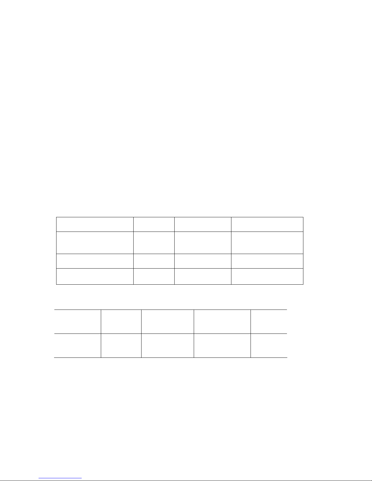
Radio control system
The RC system must feature at least five control functions and ten servos. The
transmitter should also include a servo reverse facility.
We particularly recommend MC-22s to MC-24 computer systems. The model is
designed for standard-sized servos.
We recommend the following receiver power supply: two GRAUPNER 5N-5000
NiMH packs, Order No.98903.5, which should be maintained carefully before and
after each flying session. Please note that batteries of this type do not reach full
capacity until they have been charged and discharged (cycled) several times.
You will need four suppressor filters, Order No. 1040, or a folding ferrite ring, Order
No. 98516.1 and four extension leads, Order No. 3935.18, in order to connect the
two aileron servos and two landing flap servos to the receiver, i.e. these leads are
plugged into the receiver permanently.
The following servo leads are required: one extension lead, Order No. 3935.75, for
each aileron servo, one extension lead, Order No. 3935.32 for each landing flap
servo, and one extension lead, Order No. 3935.75, for each elevator servo.
The receiver and receiver batteries should be packed in soft foam for shock
protection.
The model is suitable for standard-sized servos with an output torque of around 50
Ncm.
Adhesives
Fast-setting epoxy, e.g. UHU plus schnellfest, Order No. 962
Slow-setting epoxy, e.g. UHU plus endfest 300, Order No. 950.43
Wood glue, e.g. UHU Holzleim express, Order No. 958.60
UHU hart, e.g. Order No. 534.35
Cyano-acrylate, e.g. Order No. 5821
Cyano-acrylate, e.g. Order No. 5822
Thread-lock fluid, e.g. Order No. 952
Items required for flying the model (not included)
Fuel to suit engine: petrol / oil mix (see instructions provided with the engine)
Fuel tubing, e.g. Order No. 1325.2
Manual fuelpump, e.g. Order No. 6870
Ignition battery, Order No. 8716.5
An appropriate battery charger and charge leads are required for the electricpowered version of the aircraft.
Page 5
GRAUPNER GmbH & Co. KG D-73230 KIRCHHEIM/TECK GERMANY
Modifications reserved. No liability for printing errors 11/2010
5
Tools required (not included)
Set of cross-point screwdrivers, pointed-nose pliers, flat-nose pliers, side-cutters,
balsa knife or razor blade, set of twist drills, pencil, felt-tip pen, fine-tip soldering iron.
Assembling the JODEL ROBIN DR 400/180
Wing and undercarriage
Please don’t start assembling the model until you have checked the kit components
and the building instructions, and are familiar with the construction procedure. If you
are not happy with any component, kindly return it to your model shop without delay.
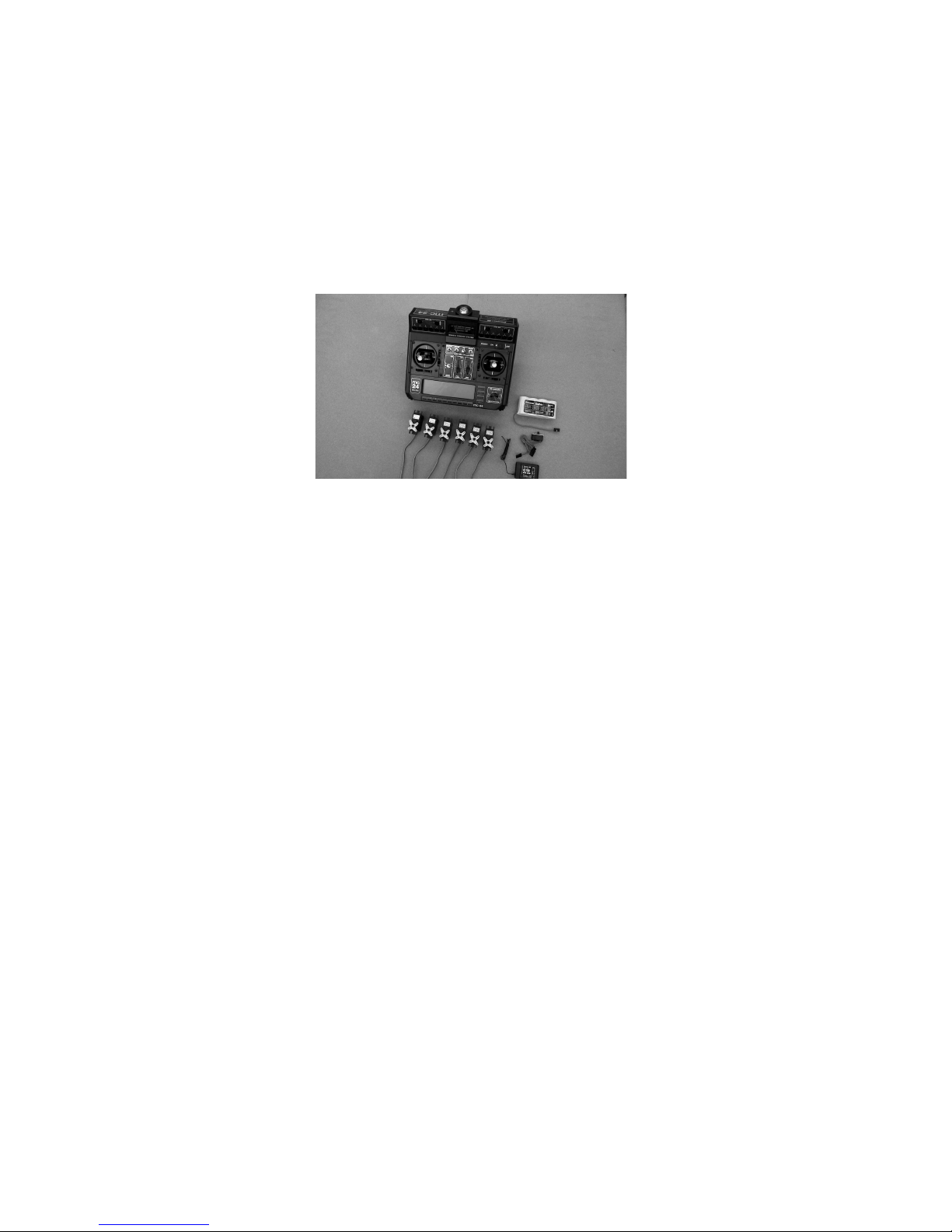
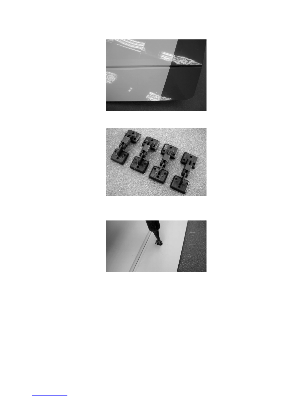
Mark a centreline on all the aileron hinges using a pencil, as shown in the photo.
The hinges can now be inserted in the ailerons as far as the pencil lines, and glued in
place. We recommend thick cyano for this: push the hinges into the slots to a depth
of about 1 mm, apply cyano on both sides, then push them in as far as the marked
lines.
When the glue has set hard, insert the projecting hinges into the slots in the wings to
check alignment; you may need to adjust the slots slightly. Now repeat the above
procedure: push the hinges into the wing to a depth of about 1 mm, apply cyano on
both sides, then push the ailerons into place, leaving a gap about 0.5 mm wide at the
hinge line. Check that the ailerons line up neatly with the wingtips.
Page 6
GRAUPNER GmbH & Co. KG D-73230 KIRCHHEIM/TECK GERMANY
Modifications reserved. No liability for printing errors 11/2010
6
Fit short pieces of heat-shrink sleeve over the landing flap hinges to prevent the jaws
opening.
Use your fingertips to locate the holes for the aileron horns, and melt the covering
film over them using the tip of a hot soldering iron.
Place the threaded socket in the hole, and remove a disc of film the same size as the
base flange. Assemble the threaded socket, the cheesehead screw, the horn lug and
the nut as shown in the photo. Repeat for the second aileron.
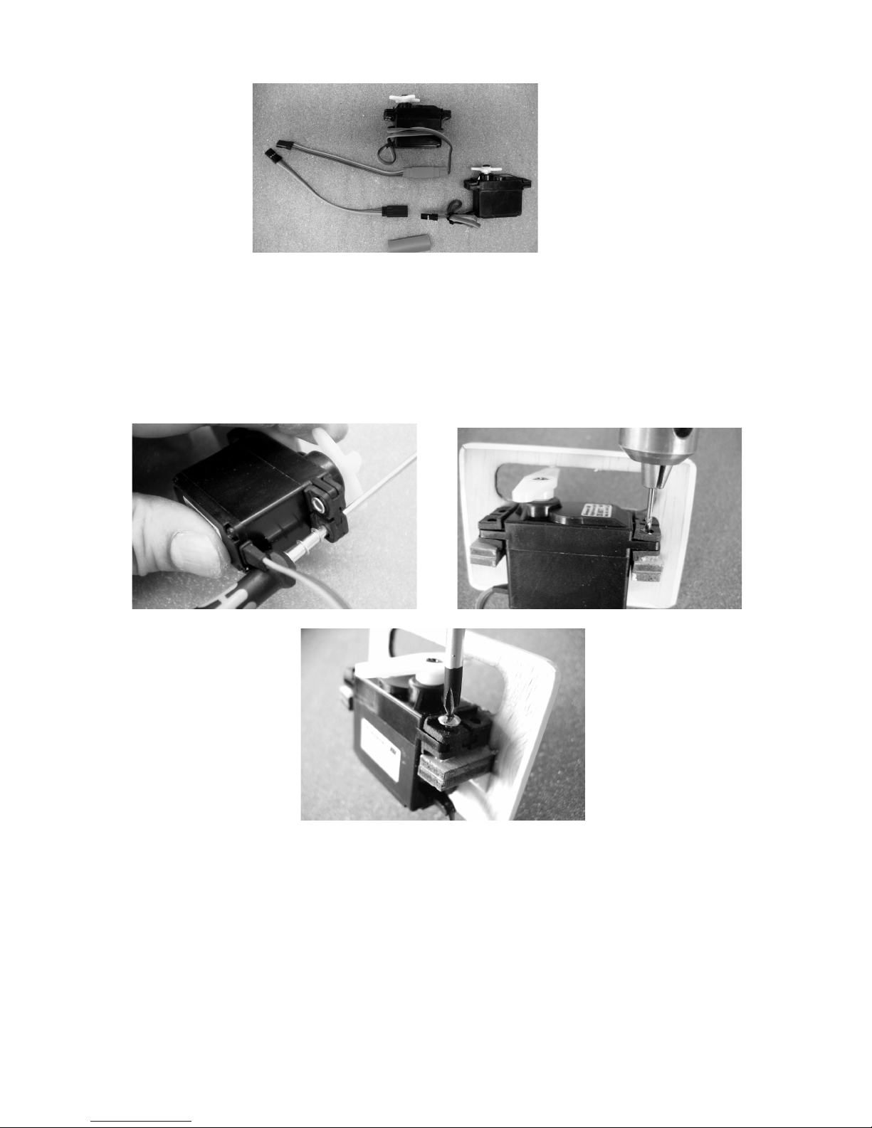
Connect the appropriate extension leads to the aileron and flap servos, and fit heatshrink sleeves round the connections to prevent them working loose; alternatively a
drop of cyano can be used. Set the servos to centre from the transmitter before fitting
the output levers on the servo output shafts.
Page 7
GRAUPNER GmbH & Co. KG D-73230 KIRCHHEIM/TECK GERMANY
Modifications reserved. No liability for printing errors 11/2010
7
Set the servos to centre by connecting them to the receiving system. The wingmounted servos can now be attached to the support blocks using the retaining
screws supplied with them: the first step is to push the rubber grommets into the
servo mounting lugs, followed by the brass tubular spacers, with the flange on the
underside. The spacers are easier to fit if you slip them on a suitable screwdriver first.
Drill 1.5 mm Ø pilot-holes in the support blocks, using the metal spacers as a guide,
then fit the servo retaining screws as shown.
The servo leads can now be pulled through the wing panels using a length of thread:
tie the thread to the servo lead just behind the connector, then pull it through until it
appears at the root rib.
Page 8
GRAUPNER GmbH & Co. KG D-73230 KIRCHHEIM/TECK GERMANY
Modifications reserved. No liability for printing errors 11/2010
8
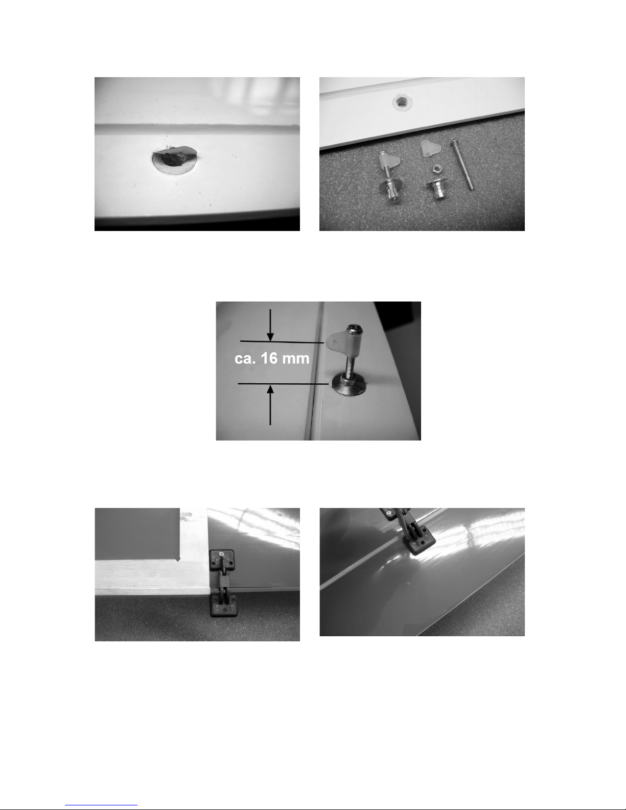
Insert the horns in the holes in the control surfaces and set them to the correct height
(see photo). The horns can now be glued in the holes. These joints must be strong,
and we recommend the use of thickened 24-hour epoxy for durability.
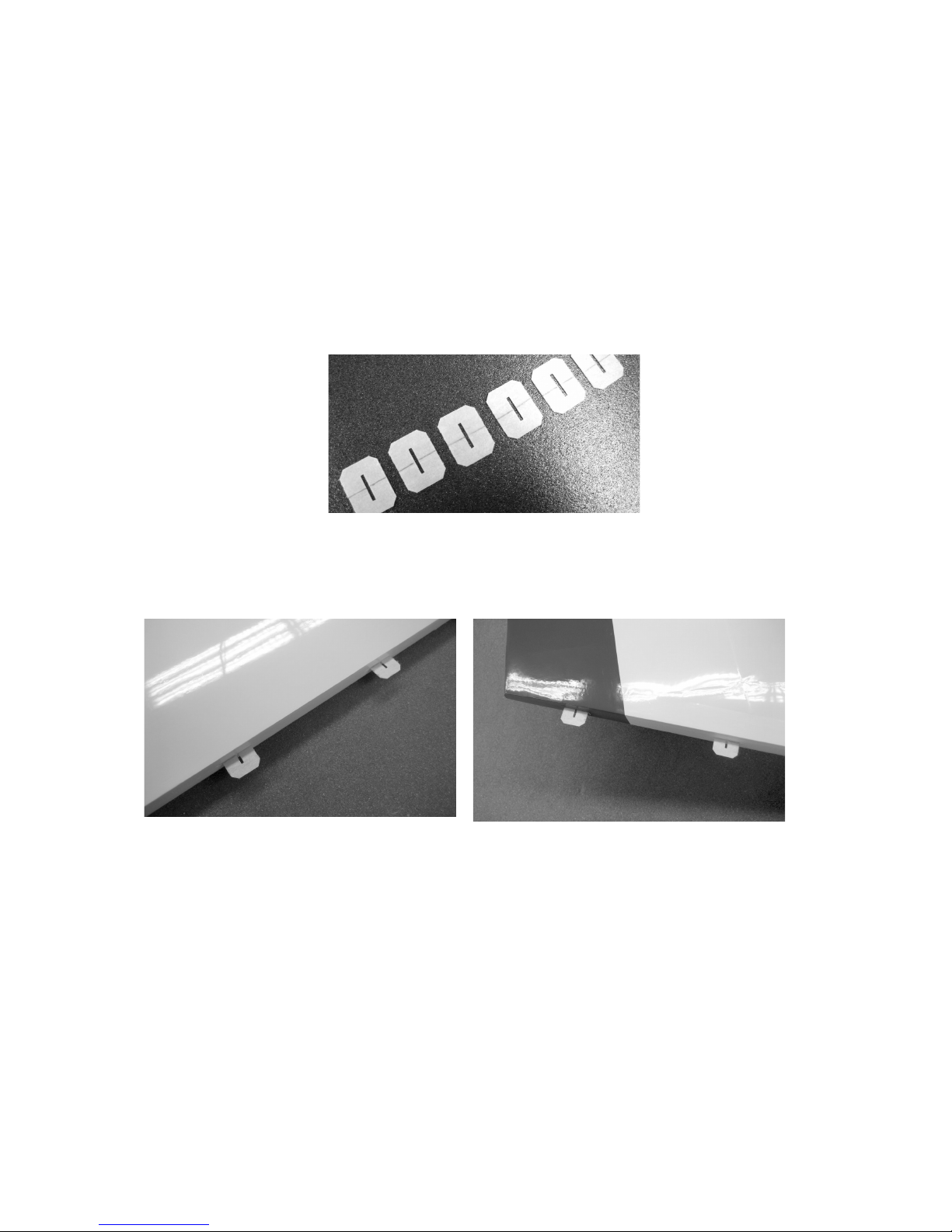
On the underside of the wing you will find marked points indicating the position of the
flap hinges. Note that the pivot axis of all the hinges must be exactly the same
distance from the wing trailing edge. Temporarily fix the hinges to the wing with one
screw, as shown in the left-hand photo, then set the hinge assembly exactly at right-
angles to the wing trailing edge using an engineer’s square or setsquare before fitting
the remaining two screws to secure the hinge to the wing. Now offer up the landing
flaps to the wings and tape them in place temporarily. Fit the retaining screws to fix
the hinges to the flaps.
Page 9
GRAUPNER GmbH & Co. KG D-73230 KIRCHHEIM/TECK GERMANY
Modifications reserved. No liability for printing errors 11/2010
9
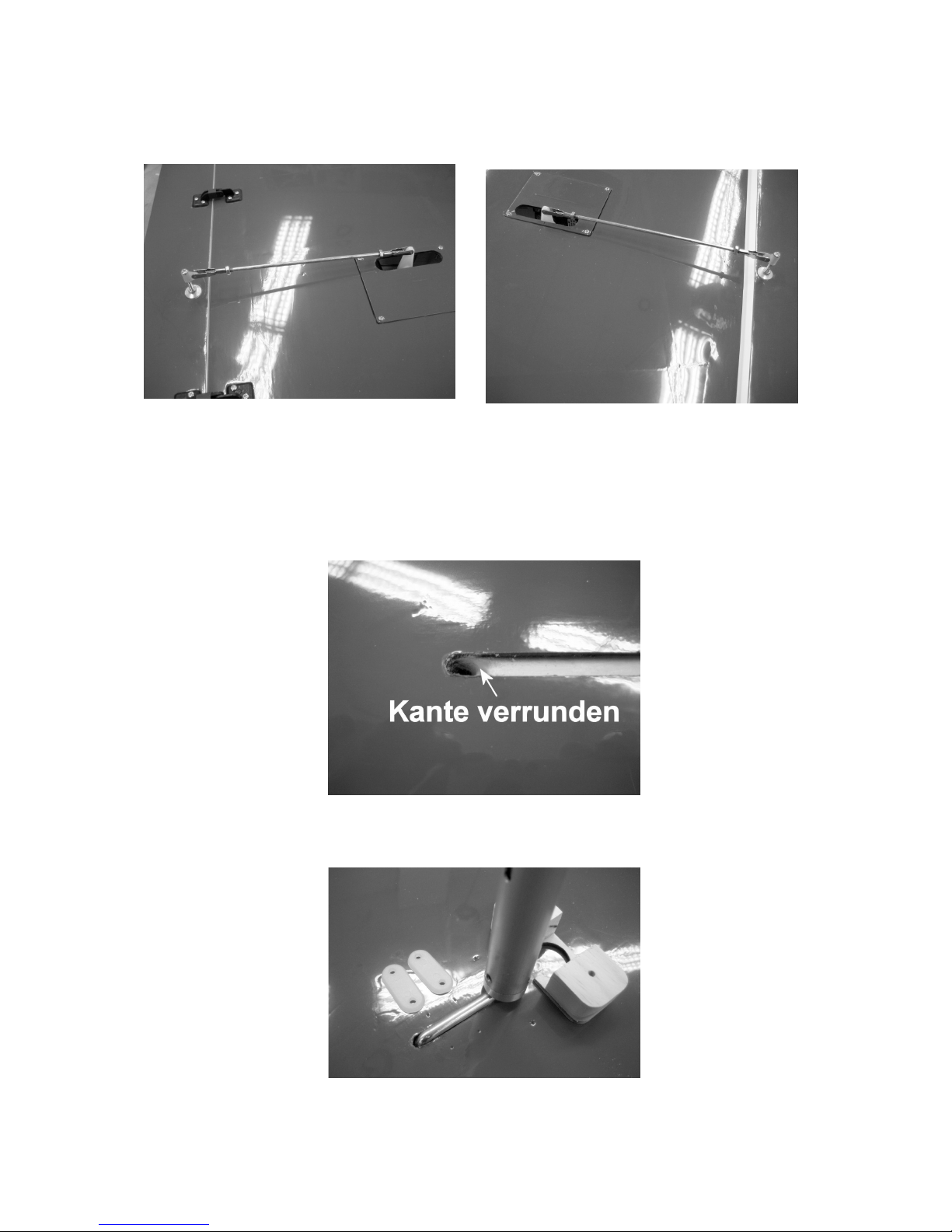
The aileron and landing flap pushrods are assembled as shown in the following
sequence of photos.
Set the servo and each control surface to neutral, then adjust the length of the
pushrods and apply a drop of UHU thread-lock fluid to prevent them shifting.
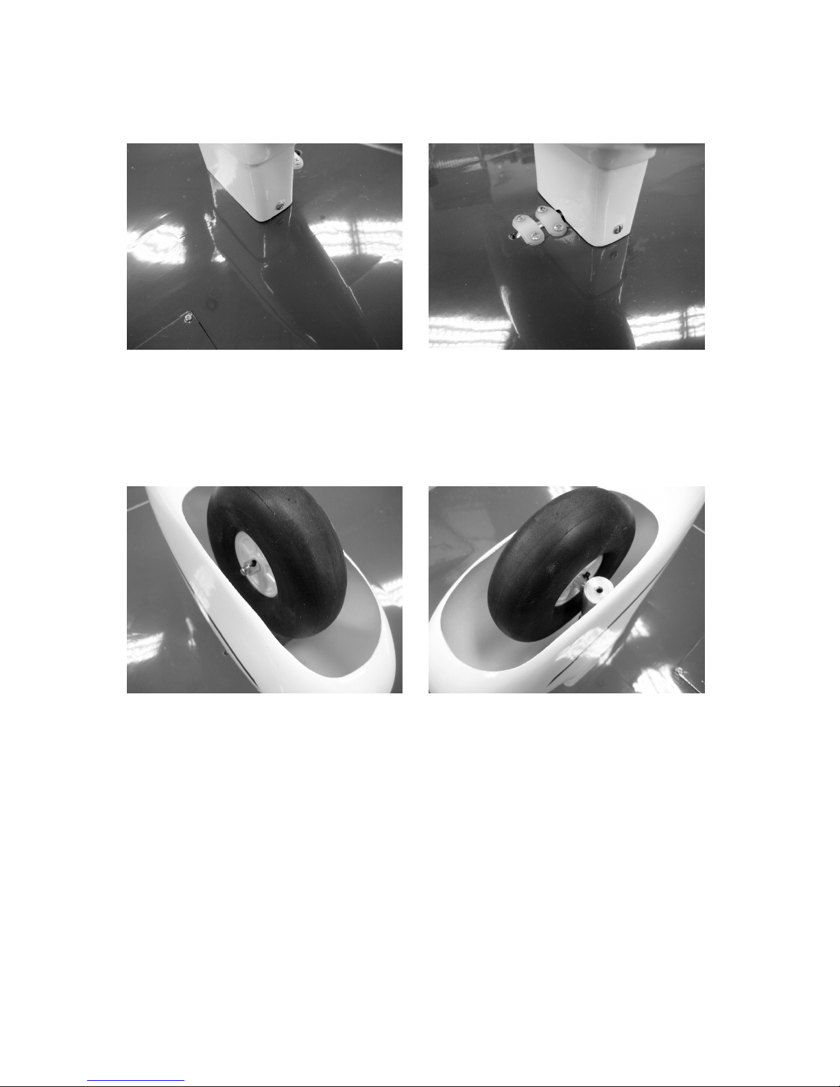
The next step is to locate the undercarriage channel in the wings using your
fingertips. Remove the film over the channels using the tip of a hot soldering iron.
Insert the undercarriage leg in the channel prior to marking the position of the two
saddle clamps and the wheel fairing support block.
Page 10
GRAUPNER GmbH & Co. KG D-73230 KIRCHHEIM/TECK GERMANY
Modifications reserved. No liability for printing errors 11/2010
10
Drill pilot-holes in the wings to suit the retaining screws, then screw the clamps and
the wheel fairing support block to the wing.
You will need to file away the inside of the two fairings to provide clearance for the
wire undercarriage units. Note that the convex side of the wheel fairings must face
outwards. Loosen the grubscrew in the end face of each spring strut, slip the wheel
axle through the cross-hole, and tighten the grubscrew firmly to clamp the axle. The
wheels can now be attached to the axles using collets and grubscrews. Apply UHU
thread-lock fluid to the grubscrews to prevent them working loose.
The wheels and wheel fairings must be aligned exactly parallel with the fuselage
centreline.
The final stage on the wing is to install the landing searchlight.
Fit the two LEDs in the white plastic holder as shown in the following photographs,
and secure them with a little UHU Kraftkleber.
Page 11

GRAUPNER GmbH & Co. KG D-73230 KIRCHHEIM/TECK GERMANY
Modifications reserved. No liability for printing errors 11/2010
11
Trim the outside edges of the plastic holder so that it fits in the recess in the wing.
Route the diode leads to the root rib using a length of thread, and run them out of the
access hole in the centre. The plastic holder can now be glued in the wing using UHU
Kraftkleber adhesive. Fix the glazing to the wing using clear adhesive tape.
Use your fingertips to locate the holes for the wing retainer screws in the wing root
area, and remove the covering film over them using the tip of a hot soldering iron.
Fuselage, tailplane, fin and noseleg
There are two options here: either the fin can be glued permanently to the fuselage,
or the tail assembly can be left detachable for ease of transport. In both cases the
tailplane panels are attached to the fin using an aluminium joiner tube and eight
socket-head screws
Page 12

GRAUPNER GmbH & Co. KG D-73230 KIRCHHEIM/TECK GERMANY
Modifications reserved. No liability for printing errors 11/2010
12
The covering film has to be removed from the mating surfaces of the fuselage and fin
before the latter can be glued in place, as shown in the photos.
Offer up the fin to the fuselage using the 12 Ø x 200 mm aluminium locating tube to
check alignment.
The fin can now be glued to the fuselage. Align the edges accurately before taping
the parts together as shown.
Attach the rudder to the fin using the hinges supplied; the technique is exactly as
described for the ailerons.
Glue the dummy light unit in the recess in the rudder.
Page 13

GRAUPNER GmbH & Co. KG D-73230 KIRCHHEIM/TECK GERMANY
Modifications reserved. No liability for printing errors 11/2010
13
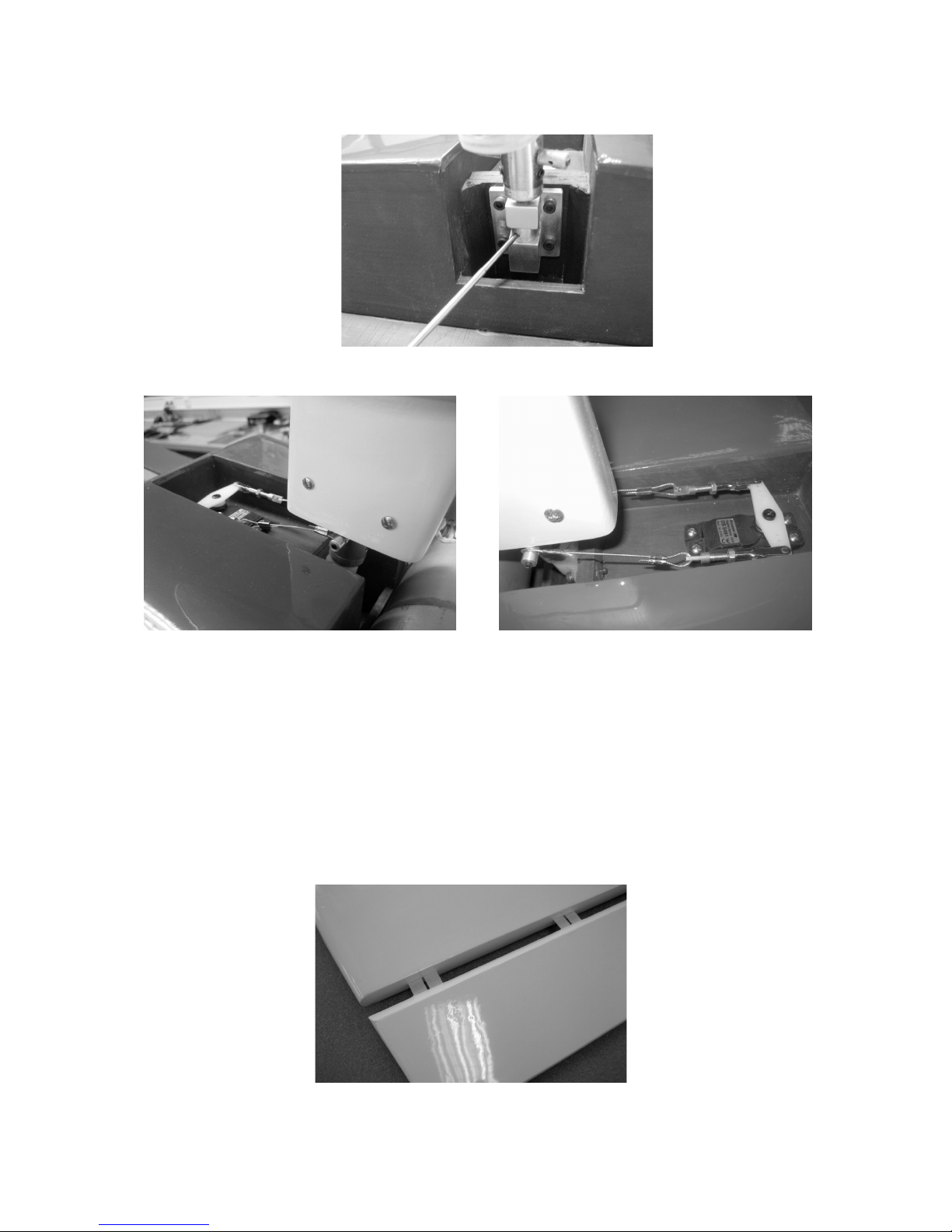
Glue the two horns in the rudder as shown in the following picture, and connect the
pull-cables to the plastic horn lugs. Please take particular care over crimping the
cables, to avoid any possibility of the rudder linkage coming adrift in flight.
The rudder servo should be installed in the servo plate at the front of the fuselage.
Connect the pull-cables to the double-ended servo output lever using threaded
couplers, nuts and clevises, as shown in the photo. Adjust the system so that the
rudder is exactly at centre when the servo is at neutral.
Fix the fairing support block to the noseleg using an M4 socket-head cap screw and
nut, as shown in the picture. Loosen the grubscrew in the end face of the spring strut,
slip the wheel axle through the cross-hole, and tighten the grubscrew firmly to clamp
the axle.
Page 14
GRAUPNER GmbH & Co. KG D-73230 KIRCHHEIM/TECK GERMANY
Modifications reserved. No liability for printing errors 11/2010
14
Fix the noseleg in the brackets by tightening the screw in the collet.
Install the nosewheel steering cables as shown in the photographs.
As with the other control systems, it is important to check that the nosewheel is
exactly at the “straight ahead” position when the steering servo is at centre. Later the
nosewheel steering servo and the rudder servo can be connected to the same
receiver socket using a Y-lead; alternatively they can be linked using a mixer.
Attach the wheel fairing to the support block using four self-tapping screws, as shown
in the photos.
The nosewheel can now be fitted on the axle and secured using two collets, as
described for the main undercarriage units.
Attach the elevators to the tailplane panels by installing the hinges, as described for
the ailerons and rudder, and fit the horns as described for the ailerons.
Page 15

GRAUPNER GmbH & Co. KG D-73230 KIRCHHEIM/TECK GERMANY
Modifications reserved. No liability for printing errors 11/2010
15
Insert the horns in the holes in the elevators and set them to the correct length before
gluing them in place permanently; we recommend thickened 24-hour epoxy for
maximum strength. Don’t forget to remove the covering film over the area of the horn
base flanges.
The two tailplane panels are joined using the 12 Ø x 330 mm aluminium tube
supplied, and are fixed to the fuselage using four M3 x 16 socket-head cap screws
on each side.
Each elevator pushrod is assembled from a length of threaded rod and two M3
clevises and nuts, as described for the ailerons and landing flaps. The length of the
two pushrods must be set in such a way that both elevators are exactly at centre
when the servos are at neutral. Remember to attach the appropriate extension leads
to the elevator servo leads before installing the servos by screwing them in the
openings in the fuselage sides.
Page 16

GRAUPNER GmbH & Co. KG D-73230 KIRCHHEIM/TECK GERMANY
Modifications reserved. No liability for printing errors 11/2010
16
Screw the aero-tow mechanism into the captive nut located just aft of the canopy.
Apply UHU thread-lock fluid to the unit and the nut to prevent them working loose.
Mount the tow-release servo in the vertical servo plate using the retaining screws
supplied in the servo accessory pack.
Connect the pushrod and set it to the correct length. We recommend that you
operate the aero-tow release mechanism using a momentary switch mounted in the
stick top. Set the servo travel carefully to avoid stalling the servo.
Installing the fueltank and engine
Assembling and installing the fueltank
Cut a piece of fuel tubing and push it onto the fueltank clunk pick-up. Push the free end
of the fuel tubing onto one of the tubes in the fueltank stopper, and check that the pickup will be able to move freely inside the tank without binding or jamming when the
stopper is in place. Use a heat-gun or match to heat the other two plastic tubes gently,
so that they can be curved: one should face down (later used to fill the tank); the
second faces up (serves later as overflow when the tank is filled). Extend each tube
with a piece of fuel tubing so that they extend to the top and bottom of the tank
respectively.
Page 17

GRAUPNER GmbH & Co. KG D-73230 KIRCHHEIM/TECK GERMANY
Modifications reserved. No liability for printing errors 11/2010
17
Now push the tank stopper, complete with pick-up and pre-formed tubes, into the
throat of the fueltank, and tighten the cross-point screw to clamp the stopper in place. It
is essential to tighten the screw to the point where the tank is completely sealed. You
can check this by holding the tank under water and blowing hard into the fuel tubes:
any air bubbles indicate a leak which must be eliminated.
Connect a further length of fuel tubing to each stub tube projecting from the fueltank
stopper.
Mark the individual fuel lines so that you can identify which is the fuel feed (to the
engine), which is the overflow, and which is the filler line.
The tank support should now be glued in the fuselage, as shown in the photo.
Ensure that the support rests against the firewall, and is located centrally. Allow the
glued joint to set hard before installing the fueltank on it.
Page 18

GRAUPNER GmbH & Co. KG D-73230 KIRCHHEIM/TECK GERMANY
Modifications reserved. No liability for printing errors 11/2010
18
Fit the fueltank in the tank compartment working from the wing saddle, passing the
three fuel lines through the hole in the firewall. Glue a piece of scrap wood behind the
tank to prevent it shifting in flight.
Be sure to use the correct grade of fuel tubing, as different types are required for
petrol engines and glow engines.
The fuel tube connected to the clunk should be connected to the engine’s
carburettor, while the overflow should run down and out of the model. The fuel filler
line can later be routed out of the model through a hole in the cowl; it should be
sealed with a plug once the fueltank is full.
Installing the engine
Four holes have to be drilled in the firewall to accept the rubber damping elements;
the hole positions are specific to the engine you intend to fit.
We recommend that you remove the tailplane or tail assembly before installing the
power plant.
Position the engine on the arms of the engine mount in such a way that the distance
between the rear face of the mount and the front of the prop driver is around 150 mm.
You will find two reference lines marked on the firewall: one vertical, one horizontal.
The point where these two lines cross indicates the centreline of the engine. Mark the
position of the engine mount screw-holes on the firewall, and drill holes at the marked
points to accept the captive nuts. Ensure that the engine can be attached to the
firewall in such a way that the silencer is positioned on the fuselage centreline;
this will require that the cylinder head be angled down by around 45°. Fix the
engine mount to the firewall using the screws supplied with the unit, and apply UHU
thread-lock fluid to prevent the screws working loose.
If you intend to install an MVVS 40, it should be attached to the firewall using the
engine mount, Order No. 2781.300.
Page 19

GRAUPNER GmbH & Co. KG D-73230 KIRCHHEIM/TECK GERMANY
Modifications reserved. No liability for printing errors 11/2010
19
Glue the throttle servo mount to the inside of the fuselage aft of the firewall, as shown
in the photo; the exact position is dictated by the throttle linkage.
Adjust the throttle pushrod so that the carburettor is half-open when the servo is at
the centre position. The servo travel must now be adjusted so that the engine stops
when the throttle stick and trim are at the “full back” position.
The throttle servo bay is covered by the cowl when it is installed.
The carburettor is actuated by a pull-cable as shown in the photos.
The next step is to cut or file out openings in the cowl to clear the silencer exhaust
pipe, sparkplug, etc.; the position and extent of the openings vary according to the
engine you are using. Position the cowl on the fuselage in such a way that there is
about 2 mm clearance all round between the front face of the cowl and the rear face
Page 20

GRAUPNER GmbH & Co. KG D-73230 KIRCHHEIM/TECK GERMANY
Modifications reserved. No liability for printing errors 11/2010
20
of the spinner backplate. Fix the cowl to the fuselage using four pan-head selftapping screws, as shown in the photos.
Installing the electric motor
The electric motor is attached to the firewall using the bulkhead, screws, nuts,
aluminium spacers and pieces of aluminium tube shown in the photograph.
As with the petrol / glow engine, the distance between the firewall and the spinner
backplate should be around 150 mm. Cut four pieces of aluminium tubing to the
length required; all four must be exactly the same length.
The motor is mounted on four spacer columns, as shown in the photo. Cut off the
four hex-head screws flush with the nuts.
Mark the position of the screw-holes on the firewall to suit the electric motor you are
using, and install the motor and bulkhead as shown in the photo.
Page 21

GRAUPNER GmbH & Co. KG D-73230 KIRCHHEIM/TECK GERMANY
Modifications reserved. No liability for printing errors 11/2010
21
Mount the speed controller for the electric motor on the front face of the firewall, as
shown in the illustration.
Create a compartment for the flight battery by gluing the battery former in the
fuselage; the distance between the firewall and the battery former should match the
size of the flight pack.
Access to the battery compartment is obtained by forming an opening hatch in the
cowl.
The size of the hatch should be chosen to suit the battery you are using: cut three
slits in the cowl as shown in the photo: the left-hand cut should lie flush with the
outside of the motor dome. The hatch can be held shut with a strip of adhesive tape,
or by a pan-head screw and a piece of scrap wood, as shown in the picture.
Glue the piece of scrap wood to the inside of the cowl.
File a slot in the end of the hatch so that it can be slipped under the screw-head in
order to secure it, as shown in the photograph.
Page 22

GRAUPNER GmbH & Co. KG D-73230 KIRCHHEIM/TECK GERMANY
Modifications reserved. No liability for printing errors 11/2010
22
Glue two strips of wood to the inside of the cowl as shown, to act as stop-strips for
the hatch. Around half of the width of the strips should be glued to the cowl, and they
must project inside the opening so that the hatch rests on them.
The canopy
Glue the instrument panel, the seat backrests and the pilot figure to the inside of the
canopy recess.
The instrument panel should be attached to the fuselage using four pan-head selftapping screws in addition to glue.
Allow the glued joints to set hard before attaching the clear canopy to the fuselage;
you can glue it in place or use small screws.
Page 23

GRAUPNER GmbH & Co. KG D-73230 KIRCHHEIM/TECK GERMANY
Modifications reserved. No liability for printing errors 11/2010
23
Final work on the model involves fitting and gluing the navigation lights, hatch covers
and aerials.
Balancing the Jodel ROBIN DR 400/180
The completely equipped model, with the fueltank empty (or the flight battery
installed), should balance level at a point about 130 - 140 mm aft of the wing root
leading edge, ideally with the nose inclined slightly down. It is easier to balance the
Jodel when it is held inverted. If necessary, adjust the position of the receiver
batteries until the model balances at the stated point. Before flying the aircraft, set the
transmitter trims to centre and ensure that all the control surfaces are also exactly at
centre (neutral).
Control surface travels for normal flying
Ailerons 25 mm up, 9 mm down
Elevators 20 mm up and down
Rudder 35 mm right and left
Landing flaps take-off 15 mm down
landing 60 mm down
We recommend that you set 30% Exponential values at the transmitter.
Page 24

GRAUPNER GmbH & Co. KG D-73230 KIRCHHEIM/TECK GERMANY
Modifications reserved. No liability for printing errors 11/2010
24
Important:
When fitting and adjusting the various linkages you should ensure that they move
freely, without binding, are able to move to their full extent - including trim travel - and
are not obstructed mechanically at any point.
When you move the rudder stick to the right, the rudder should also deflect to the
right (left stick: left rudder). Pull the elevator stick back towards you, and both
elevators must deflect up (stick forward: elevator down). If you move the aileron stick
to the right, the right aileron should rise, the left aileron fall. When you move the
throttle stick forward, the motor should run at full power; pull the throttle stick and trim
right back to their end-points, and the engine should stop. The landing flaps are best
assigned to a three-position switch.
All that remains is to wish you many hours of pleasure flying your JODEL ROBIN DR
400/180.
Yours - the team !
Page 25

GRAUPNER GmbH & Co. KG D-73230 KIRCHHEIM/TECK GERMANY
Modifications reserved. No liability for printing errors 11/2010
25
Safety notes and warnings
relating to model aircraft powered by internal-combustion engines
• Be sure to read right through the instructions covering assembly and
operation of your model before you attempt to operate it for the first time.
• These safety notes are an integral part of the instructions. Please keep
them and the operating instructions in a safe place. If you ever dispose of
the model be sure to pass them on to the new owner.
• Powered model aircraft are very demanding and potentially dangerous
machines, and call for a high level of technical knowledge and skill from
the operator, together with a responsible attitude.
• Powered model aircraft are not suitable for young persons under eighteen
years of age.
• Young people should only be permitted to operate this model under the
instruction and supervision of an adult who is aware of the hazards
involved in this activity.
• The operator of the model must be in full possession of his or her bodily
and mental faculties. As with car driving, operating a model aircraft under
the influence of alcohol or drugs is not permissible under any
circumstances.
• Radio-controlled model aircraft may only be employed for the purpose
intended by the manufacturer. They must never be used as man-carrying
machines. Any other use of this model is prohibited.
• A radio-controlled model aircraft can only work properly and fulfil your
expectations if it is built very carefully and in accordance with the building
instructions. Do not make any modifications of any kind to the design
features or materials. If you wish to avoid injuring people and damaging
property it is essential to be careful and painstaking at all stages of
building and operating your model. Nobody would climb into a full-size
light aircraft and try to fly it without completing a course of training first.
Model flying is a skill which has to be learned in just the same way. We
suggest that you ask for help from an experienced model flyer, or join a
model club or flight training school. Your local model shop and the
specialist magazines are excellent sources of information.
• It is fundamentally essential to set the Centre of Gravity (C.G.) and control
surface travels correctly. Adjust the model until they are exactly correct.
• Radio control system: satisfy yourself that your frequency is vacant before
you switch on. Check your RC system regularly as its components
eventually wear and need to be replaced or repaired. Radio interference
caused by unknown sources can occur at any time without warning. If this
should happen, your model will be uncontrollable and completely
unpredictable. Never leave your radio control system unguarded, as other
people might pick it up and try to use it. Your RC system can only work
reliably if the batteries are kept fully charged.
• Don’t ignore our warnings. They refer to materials and situations which, if
ignored, can result in fatal injury or permanent damage.
• You alone are responsible for the safe operation of your radio-controlled
model aircraft and engine.
Page 26

GRAUPNER GmbH & Co. KG D-73230 KIRCHHEIM/TECK GERMANY
Modifications reserved. No liability for printing errors 11/2010
26
• If you have any questions regarding the safe operation of your RC model
aircraft, please turn to your local model shop in the first instance as the
staff will be pleased to help you.
• Propellers and other rotating parts which are powered by an engine
represent a permanent hazard and present a real risk of injury. Don’t touch
them with any part of your body. For example, a propeller spinning at high
speed can easily slice off a finger.
• Keep well clear of the rotational plane of the propeller. You never know
when some part may come loose and fly off at high speed, hitting you or
anybody else in the vicinity. Never touch the revolving propeller with any
object.
• Take care with loose clothing such as scarves, loose shirts etc. Flapping
cloth can easily be sucked into the area of the propeller and then get
tangled in the blades. This is extremely dangerous.
• If there are passers-by or spectators at your flying site, make sure that they
are aware of the dangers inherent in your activity, and insist that they keep
a safe distance away (at least 5 m).
• Radio-controlled models should only be flown in “normal” weather
conditions, i.e. a temperature range of -5° to +35° C. More extreme
temperatures can lead to changes in battery capacity, material
characteristics and other unwanted effects.
• Model fuels are toxic; do not allow them to come into contact with your
eyes or mouth. Fuel should always be stored in clearly marked containers,
out of the reach of children.
• Never run an internal combustion engine in an enclosed space such as a
cellar, garage etc. Model engines produce lethal carbon monoxide gas just
like full-size engines.
• Engines should only be run in the open air!
• Adhesives and paints contain solvents which may be hazardous to health
under certain circumstances. Read and observe the notes and warnings
supplied by the manufacturer of these materials.
• Model fuels are volatile and highly inflammable. Keep them well away from
open flames, excessive heat, all possible sources of sparks and anything
else which could result in a fire. Do not smoke in the immediate vicinity of
fuel or fuel vapours.
• Model engines generate a lot of heat. The engine and silencer in particular
become very hot when running, and stay at a high temperature for quite a
while. Touching the hot parts can give you serious burns, so take care
especially when carrying out adjustments - wear protective gloves. Hot
engines can even start a fire under certain circumstances.
• When the engine is running it expels hot toxic gases from the exhaust
together with very hot fluid combustion residues which can burn you if you
are not careful.
• Remove all unused fuel from the fueltank and engine after every session.
• Every time you intend to operate your model check carefully that it and
everything attached to it (e.g. propeller, linkages, control surfaces etc.) is in
good condition and undamaged. If you find a fault, do not fly the model
until you have corrected it.
Page 27

GRAUPNER GmbH & Co. KG D-73230 KIRCHHEIM/TECK GERMANY
Modifications reserved. No liability for printing errors 11/2010
27
• Model engines are usually started with the help of an electric starter which
should be fitted with the appropriate adaptor where necessary. With fixedwing models an alternative is to use a “chicken stick” - a length of thick
wooden dowel with a piece of water hose pushed over it.
• Many model engines are very noisy, producing a sound level much higher
than 85 dB (A), which implies that you should wear ear defenders. Never
run a engine without the silencer fitted. Even with a silencer, model engines
can easily disturb your neighbours. Don’t run engines when other people
expect peace and quiet.
• If you start your engine when the model is standing on loose or sandy
ground, the propeller will suck up sand and dust and hurl it around, and it
could easily get in your eyes and do damage. Wear protective goggles at
such times.
• Take care that the sparkplug / glowplug clip and lead cannot get tangled in
the propeller or other rotating parts. Check the throttle linkage too.
• Take particular care when carrying the model with the engine running. Hold
the rotating parts well away from you!
• Be sure to keep an adequate supply of fuel in the tank. Don’t continue to fly
the model until the tank is drained dry.
• Never fly directly over people.
• Never fly directly towards people.
• Keep a safe distance from residential areas: at least 1.5 km “as the crow
flies”. The best solution is to join a model flying club and use the approved
flying site. Always keep well clear of high-tension overhead cables.
• Whenever you are working on the engine, make sure that you are on a safe
surface and cannot slip. Get used to holding the model really securely.
• Take-off and landing strips should be kept free of unauthorised people and
movable obstacles, particularly when a model is using the strip.
• Watch the aeroplane constantly while it is in the air. Models must always
give way to full-size aircraft.
• Don’t operate your aircraft from public roads, squares, school playgrounds,
public parks or sports grounds etc., and ensure that you are always in full
control of the model.
• It is important that you are able to stop your engine at any time. This is
achieved by adjusting the throttle so that the barrel closes completely
when you move the throttle stick and trim to their end-points. If this does
not work, pinch the fuel feed line between your fingers or pull it off the
carburettor. Never try to stop the engine by grasping the flywheel, propeller
or spinner!
• All model flyers should behave in a manner which minimises the danger to
people and property. Never act in any way which will disturb other flyers
and jeopardise safe, orderly flying at the site.
• In legal terms our models are classed as aircraft, and as such are subject to
legal regulations and restrictions which must be observed.
• Our brochure “Modellflugrecht, Paragrafen und mehr” (Model Aviation Law,
Legal Requirements and more) is available under Order No. 8034.02, and
contains a summary of all these rules. Your local model shop should have
a copy which you can read. Models fitted with glowplug / spark-ignition
Page 28

GRAUPNER GmbH & Co. KG D-73230 KIRCHHEIM/TECK GERMANY
Modifications reserved. No liability for printing errors 11/2010
28
engines may only be flown with the landowner’s permission, and third
party insurance is mandatory. There are also Post Office regulations
concerning your radio control system, and these must be observed at all
times.
• Please don’t misunderstand the purpose of these notes. We only want to
make you aware of the many dangers and hazards which can arise if you
lack knowledge and experience, or work carelessly or irresponsibly. If you
take reasonable care, model flying is a highly creative, instructive,
enjoyable and relaxing pastime.
• This model is highly pre-fabricated and can be built in a very short time.
However, the work which you have to carry out is important and must be
done carefully. The model will only be strong and fly well if you complete
your tasks competently - so please work slowly and accurately.
Important Safety Notes
You have acquired a kit which can be assembled into a fully working RC model when
fitted out with suitable accessories. However, we as manufacturers have no control
over the way you build and operate your RC model aircraft, nor how you install,
operate and maintain the associated components, and for this reason we are obliged
to deny all liability for loss, damage or costs which are incurred due to the incorrect
use of our products or due to incompetent behaviour on the part of the user, or which
are connected with such operation in any way. Unless otherwise prescribed by
binding law, the obligation of the GRAUPNER company to pay compensation,
regardless of the legal argument employed, is excluded. This includes personal
injury, death, damage to buildings, damages due to loss of business or turnover,
interruption of business or other direct or indirect consequent damage whose root
cause was the operation of the model.
The total liability in all cases and under all circumstances is limited to the amount of
money which you actually paid for the model.
This model is built and flown at the sole and express responsibility of the
operator. The only way to avoid injury to persons and damage to property is to
handle and operate the model with the greatest care and consideration at all
times.
According to the new regulation of §103 Paragraph 3 of the LuftVZO (German
Aviation Approvals Office), all model aircraft - whether slow-flyer, park-flyer, glider, or
model aircraft propelled by any form of power plant - must be insured before the
model is operated. If you are not sure about this, please ask at your local model shop
where the staff will be glad to advise you.
These safety notes must be kept in a safe place. If you ever dispose of the model, be
sure to pass them on to the new owner.
Manufacturer’s declaration:
If material defects or manufacturing faults should arise in a product distributed by us
in the Federal Republic of Germany and purchased by a consumer (§ 13 BGB), we,
Graupner GmbH & Co. KG, D-73230 Kirchheim/Teck, Germany, acknowledge the
obligation to correct those defects within the limitations described below.
Page 29

GRAUPNER GmbH & Co. KG D-73230 KIRCHHEIM/TECK GERMANY
Modifications reserved. No liability for printing errors 11/2010
29
The consumer is not entitled to exploit this manufacturer’s declaration if the failure in
the usability of the product is due to natural wear, use under competition conditions,
incompetent or improper use (including incorrect installation) or external influences.
This manufacturer’s declaration does not affect the consumer’s legal or contractual
rights regarding defects arising from the purchase contract between the consumer
and the vendor (dealer).
Extent of the guarantee
If a claim is made under guarantee, we undertake at our discretion to repair or
replace the defective goods. We will not consider supplementary claims, especially
for reimbursement of costs relating to the defect (e.g. installation / removal costs) and
compensation for consequent damages unless they are allowed by statute. This does
not affect claims based on legal regulations, especially according to product liability
law.
Guarantee requirements
The purchaser is required to make the guarantee claim in writing, and must enclose
original proof of purchase (e.g. invoice, receipt, delivery note) and this guarantee
card. He must send the defective goods to us at his own cost, using the address
stated above.
The purchaser should state the material defect or manufacturing fault, or the
symptoms of the fault, in as accurate a manner as possible, so that we can check if
our guarantee obligation is applicable.
The goods are transported from the consumer to us and from us to the consumer at
the risk of the consumer.
Duration of validity
This declaration only applies to claims made to us during the claim period as stated
in this declaration. The claim period is 24 months from the date of purchase of the
product by the consumer from a dealer in the Federal Republic of Germany (date of
purchase). If a defect arises after the end of the claim period, or if the evidence or
documents required according to this declaration in order to make the claim valid are
not presented until after this period, then the consumer forfeits any rights or claims
from this declaration.
Limitation by lapse of time
If we do not acknowledge the validity of a claim based on this declaration within the
claim period, all claims based on this declaration are barred by the statute of
limitations after six months from the time of implementation; however, this cannot
occur before the end of the claim period.
Applicable law
This declaration, and the claims, rights and obligations arising from it, are based
exclusively on the pertinent German Law, without the norms of international private
law, and excluding UN retail law.
Page 30

GRAUPNER GmbH & Co. KG D-73230 KIRCHHEIM/TECK GERMANY
Modifications reserved. No liability for printing errors 11/2010
30
The following points are important and must be observed at all times:
• Before you fly the model, check that the radio control system is working reliably,
and that all connections are secure.
• If you intend to use dry cells as a power supply, please note that they must never
be recharged. Only cells specifically marked as ‘rechargeable’ are safe to recharge.
• The batteries must be charged and the range of the radio control system must be
checked before you operate the model. In particular, the radio control system
batteries must be fully charged before each session and checked before every
flight.
• Ensure that the channel you intend to use is not already in use by other
modellers. Never fly the model if you are not certain that your channel is free.
• Read and observe the instructions and recommendations provided by the
manufacturer of your radio control system and accessory components.
• Ensure that the servos are not mechanically obstructed at any point in their
travel.
• Dry cells and rechargeable batteries must never be short-circuited.
• Remove all batteries from the model prior to transporting and storing it.
• Do not subject the model to dirty or cold conditions, or high levels of humidity or
heat.
• Secure the model and your RC equipment carefully when transporting them.
They may be seriously damaged if they are free to slide about.
Pre-flight checks
Check that the radio control system is working correctly and at full range before every
flight: fit the transmitter aerial and extend it fully, then switch on the transmitter and
the receiving system. Walk away from the model, and check that all the control
surfaces work smoothly and immediately at an appropriate distance, and deflect in
the correct “sense” (direction) relative to the stick movements.
Repeat the check with the engine running, while a friend holds the model securely for
you.
If you are a relative beginner to model flying, we recommend that you enlist the aid of
an experienced model pilot to help you check and test-fly the model.
Care and maintenance
• Clean the model carefully after every flight, and remove any dirt from the
propeller. Clean the aeroplane and the RC components using suitable cleaning
agents only. Ask your model shop for information if you are not sure.
• If the model is not to be operated for a considerable time it is important to clean
and re-lubricate all the moving parts.
 Loading...