

Page 1
Manual
CAMERA ACRO
ENGINE OFF
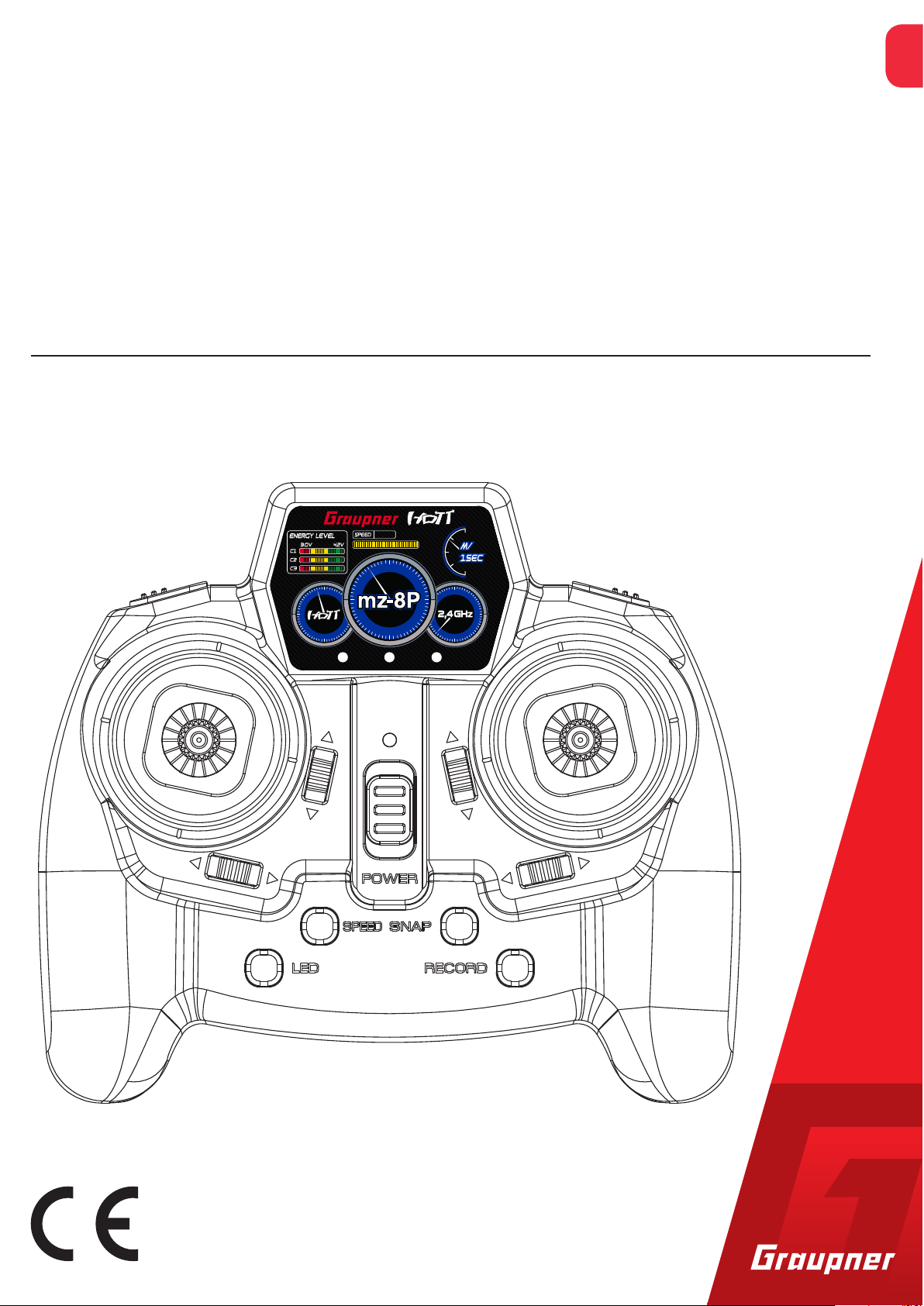
mz-8P HoTT
4 channel HoTT 2,4 GHz transmitter
No. S1032
EN
Copyright © Graupner/SJ GmbH
Page 2

2 / 24
S1032_mz-8P_V1.1sh
Page 3

Index
Introduction ......................................................................................5
Service centre ...................................................................................5
Intended use ....................................................................................6
Target group ....................................................................................6
Package content ................................................................................6
Technical data ...................................................................................7
Transmitter mz-8P HoTT .................................................................7
Symbol description ...........................................................................7
Safety notes ......................................................................................7
For your safety by handling the transmitter ..................................8
For your safety by handling the batteries ......................................8
Description of the transmitter .......................................................10
Transmitter front side ...................................................................10
Transmitter back side ....................................................................11
Transmitter power supply ..............................................................11
Data socket ......................................................................................12
Accessories ...................................................................................12
Factory reset ...................................................................................12
Starting up the transmitter ............................................................13
binding .............................................................................................13
Range test ........................................................................................14
Stick calibration ..............................................................................15
Flight control ...................................................................................16
MODE 2 .........................................................................................16
Change control mode .....................................................................17
Fail-Safe function ............................................................................17
Button functions .............................................................................18
Motor OFF button .........................................................................18
Attitude / Rate mode ....................................................................18
LED button ....................................................................................18
SPEED button ................................................................................19
SNAP button ..................................................................................19
RECORD button .............................................................................19
Auto-Flip function .........................................................................19
S1032_mz-8P_V1.1sh
Firmware update ............................................................................21
SIMPLIFIED DECLARATION OF CONFORMITY ................................22
Notes on environmental protection ..............................................23
Care and maintenance ...................................................................23
Warranty conditions .......................................................................23
3 / 24
Page 4

4 / 24
S1032_mz-8P_V1.1sh
Page 5
Introduction
Thank you very much for purchasing a Graupner mz-8P HoTT
transmitter.
Read this manual carefully to achieve the best results with your
transmitter and first of all to safely control your models. If you experience any trouble during operation, take the instructions to help or
ask your dealer or Graupner Service Centre.
Due to technical changes, the information may be changed in this
manual without prior notice. Be always updated by checking periodically on our website, www.graupner.de to be always uptodate with
the products and firmwares.
This product complies with national and European legal requirements.
To maintain this condition and to ensure safe operation, you must
read and follow this user manual and all the safety notes before
using the product!
Note
This manual is part of that product. It contains important information concerning operation and handling. Keep these instructions for
future reference and give it to third person in case you gave the
product.
Service centre
Graupner Central Service
Graupner/SJ GmbH
Henriettenstraße 96
D-73230 Kirchheim/Teck
Graupner USA
3941 Park Dr Suite 20-571
El Dorado Hills, CA 95762
Graupner in Internet For the service centers outside Germany please refer to our web site
www.graupner.de.
Servicehotline
(+49) (0)7021/722-130
Monday - Thursday:
9:15 am - 4:00 pm
Friday:
9:15 am - 1:00 pm
service@graupner.de
Website: www.graupnerusa.com
Phone: +1 855-572-4746
Email:service@graupnerusa.com
S1032_mz-8P_V1.1sh
5 / 24
Page 6

Intended use
Target group
This transmitter system must only be used for the purpose specified
by the manufacturer for operation of remote control models without passengers. Any other type of use is impermissible and may
cause significant property damage and/or personal injury. No warranty or liability is therefore offered for any improper use not covered by these provisions.
In addition, it is explicitly pointed out that you must inform yourself
about the laws and regulations applicable at your respective starting
point before starting the remote control operation. Such conditions
may differ from state to state, but this must be followed in every
case.
Note
Read through this entire manual before you attempt to install or use
the transmitter.
Package content
The item is not a toy. It is not suitable for children under 14. The
operation of the mz-8P HoTT transmitter must be performed by
experienced modellers. If you do not have sufficient knowledge
about dealing with radio-controlled models, please contact an experienced modeler or a model club.
• Transmitter mz-8P HoTT
• Transmitter manual
• Batteries
Note
Graupner/SJ constantly works on the development of all products;
we reserve the right to change the item, its technology and equipment.
6 / 24
S1032_mz-8P_V1.1sh
Page 7
Technical data
!
!
Transmitter mz-8P HoTT
Symbol description
Frequency band
Modulation
Transmitting power
Control functions
Temperature range
Operating voltage
Power consumption
Dimensions
Weight
Note
The technical data of the optional receiver are available in the manual included with the receiver.
2.4 … 2.4835 GHz
FHSS
>25 mW EIRP
8 functions of which 4 can be trimmed
-10 … +55 °C
3.4 … 4.5 V
Approximately 70 mA
Approx. 151 x 134 x 65 mm
approx. 190g without, approx. 260g
with batteries
Safety notes
Always observe the information indicated by this warning sign. Particularly those which are additionally marked with the words CAU-
TION or WARNING. The signal word WARNING indicates the poten-
tial for serious injury, the signal word CAUTION indicates possibility
of lighter injuries.
The signal word Note indicates potential malfunctions.
Attention indicates potential damages to objects.
These safety instructions are intended not only to protect the product, but also for your own and other people’s safety. Therefore please
read this section very carefully before using the product!
• Do not leave the packaging material lying around, this could be
a dangerous toy for children.
• Persons, including children, with reduced physical, sensory or
mental capabilities, or lack of experience or knowledge, or not
capable to use safely the transmitter must not use the transmitter without supervision or instruction by a responsible person.
S1032_mz-8P_V1.1sh
7 / 24
Page 8
• Operation and use of radio-controlled models needs to be
!
!
!
learnt! If you have never operated a model of this type before,
start carefully and make yourself familiar with the model's
reactions to the remote control commands. Proceed always
responsibly.
• Protect all equipment from dust, dirt, moisture. All equipment
must be protected from vibration as well as excessive heat or
cold. The models may only be operated remotely in normal
outside temperatures such as from -10°C to +55°C.
• First, always perform a range and function test on the ground
before you start using your model. Only so you can grant a safe
use! How to perform a range test is explained in the Part 2 of
the manual.
• If you have questions which cannot be answered by the operating manual, please contact us or another expert in the field.
For your safety by handling the transmitter
WARNING
Also while programming the transmitter, make sure that a connected motor cannot accidentally start. Disconnect the fuel supply or drive battery beforehand.
CAUTION
Risk of fire! Avoid every kind of short-circuit in all sockets of the
transmitter. Use only the suitable connectors. In no case the electronic component of the transmitter may be changed or modified.
Due to licensing reasons, any reconstruction and/or modification
of the product is prohibited.
Note
During transport protect the model and the transmitter from damages.
For your safety by handling the batteries
CAUTION
8 / 24
• Protect the batteries from dust, moisture, heath and vibrations. Only use in dry locations.
• Do not use any damaged battery.
S1032_mz-8P_V1.1sh
Page 9

• Batteries may not be heated, burned, short-circuited.
• If handled improperly, there is a danger of fire, explosion, irritation and burns.
• Leaked electrolyte is caustic and should not be touched or
come into contact with your eyes. In case of emergency, rinse
with a large quantity of water and consult a Med. Doctor.
• Do not try to recharge the batteries included in the package!
Those are non-rechargeable batteries.
• Stock the batteries in dry and fresh conditions.
• Dispose of the battery in the proper disposal centers.
S1032_mz-8P_V1.1sh
9 / 24
Page 10

Description of the transmitter
CAMERA ACRO
ENGINE OFF
10
11
12
13
14
88
Transmitter front side
1
8
2
1 Motor "ON/OFF" switch
3 4 65
7
8
9
2 LED, yellow (motor-OFF function) LED ON: Motor OFF
3 LED, red (indicates camera recording) blinking: Recording
4 LED, green (if off indicates: Attitude mode, if on: Rate
mode)
5 LED, red
flashing: no connection to receiver
solid ON: correct connection to receiver
Blinking and 2x beeps: Flight battery under voltage
Blinking and 4x beeps: Transmitter power source under
voltage
6 "Attitude / Rate mode" pushbutton
7 Right-hand control stick
8 Trims
9 "Snapshot / C8-switching“ pushbutton
10 "Video ON/OFF" pushbutton
11 ON/OFF switch
12 "Binding / Video channel switching" pushbutton
10 / 24
13 "Control sensitivity" pushbutton
15 Left-hand control stick
S1032_mz-8P_V1.1sh
Page 11

Transmitter back side
16
16
19
19
16
16
17
16
18
16
16 Case screws
Transmitter power supply
17 Data socket
18 Battery case
19 Fixture points for attachment holder
The mz-8P HoTT transmitter comes standard with three alkaline bat-
teries. (subject to modification).
Installing transmitter batteries
To insert the included transmitter batteries remove the battery case
cover on the back side of the transmitter. Insert the included batteries in the holder paying attention to the correct polarity (see figure)
Alternatively, AA size NiMH batteries can be used at any time. However, these are always to be charged outside the transmitter.
The voltage level of the transmitter power supply is indicated by the
status LED during operation:
As soon as the power supply to the transmitter drops below 3.2 V,
the normally constant red status LED starts flashing in rapid succession. At the same time, acoustic warning signals sound in the form
of a 4x beep. At least now, the operation must be stopped immediately and the batteries have to changed or charged, only if rechargeable batteries are used!
S1032_mz-8P_V1.1sh
11 / 24
Page 12

Data socket
Accessories
Removing the transmitter batteries
If the transmitter is not going to be used for a long time, the batteries should be removed from the device to avoid damages to the
transmitter due to electrolyte leaks.
The data socket is used to connect an optional Bluetooth module as
well as to update the transmitter or change its control mode.
• SMART-BOX, No. 33700
Display and programmer for telemetry data and devices
• external Bluetooth module, No. S8351
for wireless transmission of telemetry data to a compatible
Android ™ smartphone and comfortable programming of receivers and sensors via smartphone.
• USB interface No. S8500
Factory reset
• micro USB cable, No. 33002.OTG
for wired display of telemetry data on one and programming via
Android ™ smartphone
If necessary, all values stored in the transmitter can be deleted by a
reset and reset to the factory settings. To do this, proceed as follows:
Push and hold all the trims to the inside and then switch the transmitter on.
Note
All settings made in the meantime are reset to the default values!
Starting up the transmitter
To switch on the transmitter, push the POWER button to the front.
Immediately after switching on, a short beep will sound; the yellow
motor OFF LED lights up and the central status LED of the transmitter lights up or flashes depending on the current status.
Status Description Red status LED Red LED Yellow LED Green LED Buzzer
Binding Tx unbound Blinks 1x / sec 1x low
Tx bound ON 2x low
Correct contact to rx ON 2x low
Range test Blinks quickly 2x low / 2sec
Error Tx volt too low Blinks quickly 4x high / 2sec
Sensor warning 3x high / 2sec
12 / 24
S1032_mz-8P_V1.1sh
Page 13

Rx volt / temp Blinks quickly 2x high / 2sec
Out of range Blinks slowly 1x high / 2sec
System error 1x low / 2sec
Normal
mode
Program
mode
Stick calibration
Flip mode 360° FLIP active 10x high / 2 sec
Motor
OFF
Camera Snapshot ON/OFF
Trim inc/dec 1x low / click
Trim 0% 1x high / click
Program mode start Blinks 1x 1x low
Program mode end 1x low
Servo reverse (normal) Blinks 1x 5x 1x low
Servo reverse (reverse) Blinks 2x 5x 2x low
ATV 100% 1x high
Fail Safe mode start Blinks 2x 2x low
Fail Safe „HOLD“ Blinks 1x 5x 1x low
Fail Safe „POS“ Blinks 2x 5x 1x high
Calibration mode start Blinks 1x 3x
Calibration ended Blinks 3x 3x Blinks 3x 3x 2x low
„Deadband“ setting Blinks / 3sec
Motor cut OFF Blinks
Video record Blinks slowly ON: 1x low / OFF: 2x high
quickly
3x low
binding
If no copter is still bound to the transmitter or if another copter is to
be bound to the transmitter, proceed as follows:
Binding step-by-step
1. Switch on transmitter.
The red status LED of the transmitter flashes once per second.
2. Start the copter by plugging in the drive battery or switching on
the power supply.
3. Possibly put the copter in bind mode according to its instructions.
4. Press the LED button on the bottom left of the transmitter.
If the binding process was successful, the red status LED of the
transmitter lights up constantly. Otherwise the process has to be
repeated.
Notes
• After a binding process, the highest control sensitivity is always
preset by default. If you press the "SPEED" button, you can
reduce it to "medium" (2-way sound) or "low" (1-way sound).
S1032_mz-8P_V1.1sh
13 / 24
Page 14

Range test
• If a copter has already been bound to the transmitter and this
combination is to be put back into operation, then for safety reasons, first the transmitter and then the copter must be put into
operation. The corresponding connection is then automatically
established.
By triggering the integrated range test by simultaneously pressing
the transmitter's "SPEED" and "SNAP" buttons, the transmit power
of the mz-8P HoTT transmitter is reduced so that a functional test
can already be performed at a distance of 5 to about 10 m. After the
90 second range test, the transmitter switches back to full output,
and the signal tone stops. Alternatively, however, the range test can
be ended manually at any time by pressing the "SPEED" and "SNAP"
keys again.
Perform the range test for the Graupner-HoTT system according to
the following instructions. It is useful to have an assistant to help you
with the range test.
1. Switch on the remote control and then connect a battery to the
copter or switch on its power supply. Wait until both devices signal a correct connection. Now the motors or propellers should
run controllably.
2. With the motor OFF function activated, place the model on level
ground (pavement, short lawn or earth) so that it is at least 15
cm above the ground. It may therefore be necessary to place a
support underneath the model during the test.
3. Hold the transmitter at hip level at a slight distance from your
body.
4. Deactivate the motor OFF function and start the range test by
simultaneously pressing the "SPEED" and "SNAP" keys.
5. The red status LED on the transmitter will start to blink quickly
and a signal tone is emitted twice each two seconds.
6. Move away from the model within these 90 seconds while moving the sticks. Make sure, however, that the model does not stand
out in an uncontrolled manner. If you detect an interruption in
the link within a range of about 5 - 10 m at any time, attempt to
reproduce it.
14 / 24
7. Move further away from the model until it does not respond perfectly.
8. At this location, wait for the remainder of the test period with the
still operable model. The model should still react to control commands once the range test is finished. If this is not 100 % the
case, do not use the system and contact our Service department.
9. After the 90 second range test, the transmitter switches back to
full output, and the signal tone stops. By simultaneously pressing
S1032_mz-8P_V1.1sh
Page 15

Stick calibration
the "SPEED" and "SNAP" buttons, the range test can be stopped
earlier at any time.
10. Perform a range test before each flight, and simulate all control
movements that could occur during the flight. In order to guarantee a safe model operation, the range must always be at least
5 - 10 m on the ground.
Attention
Never start a range test on the transmitter during normal model
operation!
If the middle position of your self-neutralizing stick does not exactly
correspond to 0% control course, then you can check it yourself and
correct it if necessary.
Stick calibration step by step
1. Eventually disconnect the copter by unplugging the battery.
2. Put the transmitter into programming mode by pressing and
holding the left control stick.
An acoustic signal sounds and the central red LED flashes 3 times
per second.
About another three seconds later, an acoustic signal sounds
again.
3. Now successively move both joysticks to the respective end stops
and then back to the middle.
4. Keep both sticks in the middle position.
After approx. 3 seconds, an acoustic signal sounds and the central red and the yellow "Acro" LEDs on the top right flash 3x each
3x per second.
5. Now press the left stick for about one second.
As soon as the left, yellow, "motor OFF" LED lights up and the central red LED flashes slowly, the process has been completed correctly and the stick can be released. Otherwise the entire process
has to be repeated.
6. The copter can be put back into operation.
S1032_mz-8P_V1.1sh
15 / 24
Page 16

Flight control
CAMERA ACRO
ENGINE OFF
CAMERA ACRO
ENGINE OFF
CAMERA ACRO
ENGINE OFF
MODE 2
Climb and sink
Turn (yaw)
Roll to the right and left
16 / 24
S1032_mz-8P_V1.1sh
Page 17

CAMERA ACRO
ENGINE OFF
Change control mode
Forward and backward (nick)
The transmitter mz-8P HoTT is delivered as standard only in Mode 2,
with throttle / pitch and yaw on the left. This configuration can be
changed via firmware update to Mode 4, with throttle / pitch and
yaw on the left.
The required software "S1032_MZ-8P_M34_xxx.bin" can be downloaded free of charge from the mz-8P HoTT product page at
www.graupner.de.
Fail-Safe function
MODE 2 (Throle/Pitch le)
Motor / Pitch
Yaw
Yaw
Motor / Pitch
Nick
Roll
Nick
MODE 4 (Throle/Pitch le)
Motor / Pitch
Roll
Roll
Motor / Pitch
Nick
Yaw
Nick
Yaw
Note
After switching to mode 4, the control function "yaw" is on the right
and the roll function on the left control stick.
If the radio connection is interrupted for less than approx. 0.5 seconds, the factory setting is to "hold" the control signals last recognized as correct. If the disturb lasts longer, the motors will be
switched "OFF" after expiry of this period.
S1032_mz-8P_V1.1sh
17 / 24
Page 18

Button functions
Motor OFF button
Attitude / Rate mode
After switching on the transmitter, the transmitter's motor OFF function is always active for safety reasons. In order to be able to put the
motors of the copter into operation, if necessary, bring the throttle/
pitch control stick to its stop on the idling side and then press the left
front key. As soon as an acoustic signal sounds and the yellow motor
OFF LED goes out, the motors of the copter start to run at low speed
and can be regulated accordingly with the throttle / pitch control
stick.
To switch off the motors, press the motor OFF button again.
After switching on the transmitter, the Attitude mode is always
active. To switch from the Attitude mode to the Rate mode, and vice
versa, press the button on the right front of the transmitter:
• When switching to the Rate mode, a low signal sounds and the
green ACRO LED starts to light steadily.
LED button
• When switching to the Attitude mode, a bright 2x signal sounds
and the green ACRO LED goes out.
1. If the red status LED of the transmitter flashes, pressing this key
triggers the binding process.
2. If the red status LED of the transmitter is constantly lit, any short
pressure on the Alpha 110 will switch the large white front LED,
eg. the No. S5012.RFH, S5012M1.RTF and S5012M2.RTF, the
front LED on and off.
3. If the status LED of the transmitter is constantly red, any long
press with the motor stop function activated will rotate in rotation to the next FPV channel and, if present, the LED illumination.
For example, on the copters S5012.FPV, 16570.FPV, 16572.FPV
and the FPV transmitter, No. 16570.123, in combination with the
Flight Control S1038 and LED lighting.
18 / 24
S1032_mz-8P_V1.1sh
Page 19

SPEED button
SNAP button
In the "Motor OFF" mode of the transmitter, each press of this button will rotate in rotation to the next of three preset path settings:
• 3-times signal
Pitch -94 … +100 %
Roll/Nick/Yaw ±100 %
(Standard setting after binding a receiver)
• 2-times signal
Pitch: -94 … +55 %
Roll/Nick/Yaw ±60 %
• 1-times signal
Pitch: -94 … +55 %
Roll/Nick/Yaw ±40 %
1. Each short press triggers a snapshot. For confirmation, the red
CAMERA LED lights up for approx. 1 second each.
RECORD button
Auto-Flip function
2. Each long press switches channel 8 between + and -100%. Only
usable with compatible copters.
Pressing this button starts the video recording on a compatible copter. As confirmation, a low beep sounds and the CAMERA LED starts
to light rhythmically. Another pressure stops the recording. The red
flashing CAMERA LED goes out and a bright 2x signal sounds.
If the copter is in attitude mode, a compatible copter can independently flip or roll over in any direction.
Trigger a rollover step-by-step
1. Press the completely self-neutralizing control stick.
For about 5 seconds, a fast beep will sound.
2. As long as the beep is heard, move the roll or pitch stick more
than 50% of its way toward the end stop while simultaneously
"accelerating" so that the copter does not lose altitude during the
flip.
S1032_mz-8P_V1.1sh
The copter makes a self-rollover in the direction in which it is
headed.
19 / 24
Page 20

Note
Possibly, after a rollover, the position of the copter must be manually corrected, as this does not always return to its exact starting
position.
Attention
If the auto flip function is used many times repeatedly the receiver
can loose the attitude information and the copter may move in an
uncontrolled direction. Quiet hovering for about 30 seconds or a
short stopover helps recalibrate the location information.
20 / 24
S1032_mz-8P_V1.1sh
Page 21

Firmware update
Firmware updates of the transmitter are carried out via the back
DATA connection with the aid of a PC with Windows 7 ... 10. You will
also need a USB interface, order no. 7168.6, and adapter lead, order
no. 7168.6A or 7168.S, which are available separately.
The programs and files required can be found in the Download area
for the corresponding products at www.graupner.de.
Connect the adapter lead to the USB interface. The polarity of the
plug-in system cannot be reversed. Note the small chamfers on the
sides. Do not use force, the plug should click into place easily.
Plug the other end of the adapter cable into the jack marked "S + -"
on the back of the transmitter upon the battery case. Do not apply
force. The plug should be pushed all the way in with the black or
brown cable facing the right side of the "-" pin.
The update is carried out via the "HoTT Device" or "HoTT device"
program section of the "Firmware_Upgrade_gr_Studio" program
found under "Device" or "Devices". Please follow the notes of the
software. The further procedure is also described in detail in the
manual contained in the data package. You can also download these
from the download page of the product at www.graupner.de.
S1032_mz-8P_V1.1sh
21 / 24
Page 22

SIMPLIFIED DECLARATION OF CONFORMITY
Graupner/SJ hereby declares that the transmitter system type
S1032 mz-8P HoTT complies with the Directive 2014/53/EU.
The full text of the EU Declaration of Conformity is available at the
following Internet address: www.graupner.de
Manufacturer
Graupner Co., Ltd
Post Code: 14557
8th F, 202 Dong, Chunui Techno-Park II, 18, 198 Street
Bucheon-ro, Wonmi-Gu, Bucheon-Shi, Gyeonggi-do
South Korea
22 / 24
S1032_mz-8P_V1.1sh
Page 23

Notes on environmental protection
P
If this symbol is on the product, instructions for use or packaging, it
indicates that the product may not be disposed with normal household waste once it has reached the end of its service life. It must be
turned over to a recycling collection point for electric and electronic
apparatus.
Individual markings indicate which materials can be recycled. You
make an important contribution to protection of the environment by
utilizing facilities for reuse, material recycling or other means of
exploiting obsolete equipment.
Batteries must be removed from the unit and disposed of separately
at an appropriate collection point. Please inquire if necessary from
the local authority for the appropriate disposal site.
Care and maintenance
The product does not need any maintenance. Always protect it
against dust, dirt and moisture.
Clean the product only with a dry cloth (do not use detergent!) lightly
rub.
Warranty conditions
Graupner/SJ GmbH, Henriettenstrassee 96, 73230 Kirchheim/Teck
grants from the date of purchase of this product for a period of 24
months. The warranty applies only to the material or operational
defects already existing when you purchased the item. Damage due
to misuse, wear, overloading, incorrect accessories or improper handling are excluded from the guarantee. The legal rights and claims
are not affected by this guarantee. Please check exactly defects
before a claim or send the product, because we have to ask you to
pay shipping costs if the item is free from defects.
These operating instruction are exclusively for information purposes
and are subject to change without prior notification. The current
version can be found on the Internet at www.graupner.de on the
relevant product page. In addition, the company Graupner/SJ has
no responsibility or liability for any errors or inaccuracies that may
appear in construction or operation manuals.
Not liable for printing errors.
S1032_mz-8P_V1.1sh
23 / 24
Page 24

 Loading...