

Page 1
Manual
33516 Receiver GR-32 HoTT
CONTENTS:
1. General Note .............................................................................................................. 01
2. Functions .................................................................................................................... 01
2.1. Binding ......................................................................................................................... 01
2.2. Binding Multiple Receivers .......................................................................................... 01
2.3. Fail-Safe Function ........................................................................................................ 02
3. Receiver ...................................................................................................................... 02
3.1. Connections ................................................................................................................. 02
3.2. Low Voltage Warning ................................................................................................... 03
3.3. Temperature Warning ..................................................................................................03
4. Firmware Update ........................................................................................................ 03
4.1. Receiver ......................................................................................................................03
4.2. Update Procedure ........................................................................................................ 03
5. Declaration of Conformity ......................................................................................... 05
6. FCC Information..........................................................................................................06
7. Warranty .....................................................................................................................08
Manual V1.2
Revision: Oktober 2013
GRAUPNER/SJ GmbH – Postfach 1242 – 73230 Kirchheim/Teck – www.graupner.de
Page 2

Thank you for purchasing the Graupner HoTT 2.4 System Please read through this entire manual before
you attempt the installation and usage of your Graupner HoTT 2.4 System!
A hardware antenna diversity system always switches to the better antenna signal and for transmission
always uses the antenna that was last used for receiving. This ensures that the back channel data
are always sent via the better-positioned antenna. Without additional sensor systems, the parameters
receiver voltage and temperature, as well as signal strength are transmitted. Connector for one telemetry sensor and for the sum signal input or output. The receiver does have 6 power inputs for strong
servos.
These operating instructions are part of this product. They contains important notes to the operation and
handling. Please take this into consideration when you pass on the product to third parties. Neglect of
the operating instructions and the safety instructions lead to expiring the warranty.
Graupner/SJ constantly work on the advancement of all remote control systems; changes of the scope of
delivery in form, technology and equipment we must reserve ourselves therefore. Please have understanding for the fact that from data and illustrations of this operating instructions no requirements can be derived.
Please keep these instructions for further reference!
1. GENERAL NOTE
When switching on or adjusting the radio control system it is essential to keep the transmitter aerial at
least 15 cm away from the receiver aerials at all times. If the transmitter aerial is too close to the receiver
aerials, the receiver will be overloaded, causing the green LED starts ashing. The transmitter responds
by emitting a beep once every second; the red LED also goes out. The radio control system is now in
Fail-Safe mode.
If this should occur, simply increase the distance between the aerials until the audible warning signal
ceases, and the red LED on the transmitter lights up again; at the same time the green LED on the
receiver should glow constantly.
2. FUNCTIONS
2.1. Binding
When you wish to use the Graupner HoTT 2.4 GHz receiver with a particular transmitter, the rst step
must always be to “bind” the unit to “its” Graupner HoTT 2.4 GHz RF module (transmitter). This “binding”
procedure only needs to be carried out once for each combination of receiver and RF module. The units
supplied in the set are already bound to each other at the factory, i.e. the binding procedure described in
the following section only needs to be carried out when you wish to use an additional receiver. However,
it can also be repeated at any time if required, e.g. after changing transmitters. When binding is required,
this is the procedure:
• Switch the transmitter and receiver on.
• Locate the BIND / RANGE button on the back of the transmitter, and hold it pressed in while you
press and hold the SET button on the receiver. Both LEDs on the back of the transmitter now glow
constantly, and the red LED on the receiver ashes.
• If the red LED expires and the green LED on the receiver begins to glow permanently within about
ten seconds, this indicates that the binding process is complete. You can now release both buttons,
and your transmitter / receiver combination is ready for use.
• However, if the green LED on the receiver continues to ash for longer than ten seconds, then the
binding process has failed. If this should occur, repeat the whole procedure.
2.2. Binding“ multiple receivers in one model
If required, it is also possible to bind multiple receivers to the transmitter for a particular model. The rst
step is to bind each receiver individually using the procedure already described.
When the system is in use, the receiver which was bound last is the Master receiver (which is switched
01 Manual Receiver GR-32 Graupner HoTT 2.4
Page 3
on rst for the modules Order No. 33300, 33301 and 33302). Any telemetry sensors installed in the
model must be connected to this unit, as only the Master receiver transmits sensor
data using the downlink channel. The second and all further receivers operate in parallel with the Master
receiver but in Slave mode, with the downlink channel switched off.
The control functions can also be distributed amongst multiple receivers; this is carried out using the
Channel Mapping function of the SMART-BOX (Order No. 33700). In the same way it is possible to assign one control function to multiple receiver outputs; a typical example would be the use of two servos
for each aileron instead of only one, etc.
2.3. Fail-Safe function
In its default state (as delivered) the receiver is set to “Hold” mode, i.e. if a fail-safe situation occurs, all
the servos connected to it maintain the last position detected as valid. In this mode the green LED on
the receiver starts ashing when interference occurs, and the red LED on the transmitter goes out. The
transmitter also starts beeping about once per second as an audible warning.
You can exploit the safety potential of the fail-safe option by at least programming the throttle channel to
respond to a fail-safe situation: the throttle channel of an engine-powered model should be set to idle,
the throttle channel of an electric-powered model to “stop”, and the throttle channel of a model helicopter
to “Hold”. If interference should occur, these settings will help prevent the model ying out of control,
possibly causing personal injury or property damage.
Please refer to the appropriate section in your RC system instructions for the procedure.
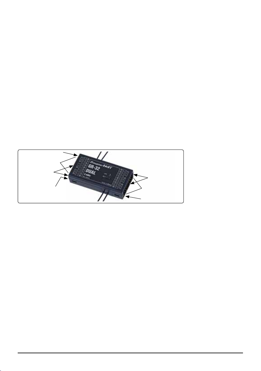
3. RECEIVER
Battery socket „B“
Servo sockets
7-12/15-16
Battery socket „B“
Socket for
sum signal „S“
Battery socket „B“
Servo sockets
1-6/13-14
Battery socket „B“
3.1 Connections
Plug the servos into the row of sockets on both sides of the receiver. The connector system is polarised;
note the small chamfer on one edge. Never use force - the plugs should engage easily and fully. The
socket polarity is also marked on the case: brown wire (-), red (+) and orange (signal).
The servo sockets of the Graupner-HoTT 2.4 receiver are numbered. It is also possible to program
socket „S“ for the sum signal using the SMART-BOX (Order No. 33700). This is important for certain
optional devices which require this signal.
Power supply
The sockets marked “- +/B” are intended only for the battery connection. Connect the power supply
preferably with the socket(s) that are close to the servos. When using High Power servos you may use
all battery connectors depending on the battery power, when necessary with three PRX-receiver power
supplies.
If you connect to each battery terminal a separate battery, make sure that the batteries have the same
rated voltage and rated capacity. Do not connect different types of batteries or batteries with highly different charging states, because this may lead to short-circuit-like effects. Use in such cases, for safety
reasons, voltage stabilizers like the PRX-5A-receiver power supplies (No. 4136) between the battery
and receiver.
Manual Receiver GR-32 Graupner HoTT 2.4 02
Page 4
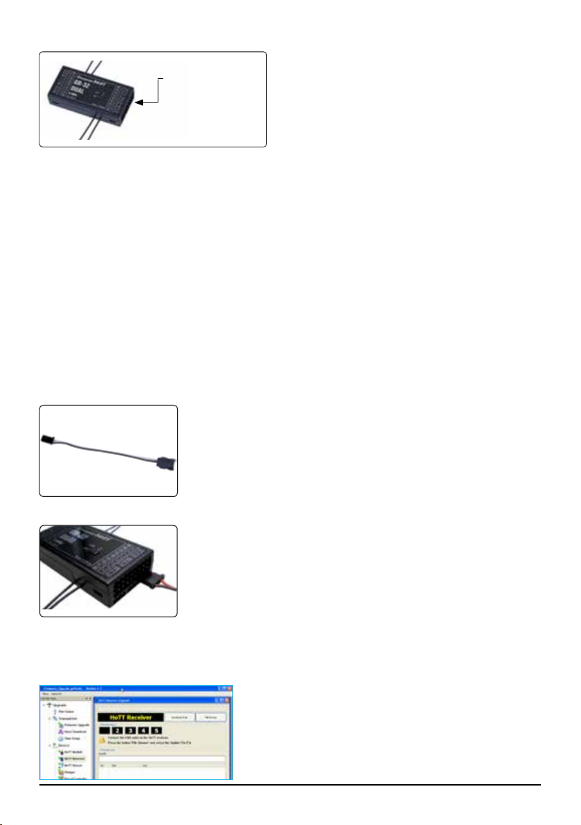
Telemetry
Telemetry socket
(socket „T“)
3.2. Low voltage warning
If the receiver voltage falls below 3.8 V, the transmitter’s RF module generates a low voltage warning in
the form of a “general alarm sound”: a steady beeping at intervals of about one second.
3.3. Temperature warning
If the receiver temperature falls below -10° C or exceeds +70° C, the transmitter’s RF module generates
a temperature warning in the form of a “general alarm sound”: a steady beeping at intervals of about
one second.
4. FIRMWARE UPDATE
Firmware updates for the receiver can be transferred via the socket „T“ in conjunction with a PC running
Windows XP, Vista or 7. For this you also require the USB interface, Order No. 7168.6, and the adapter
lead, Order No. 7168.6A, which are available separately.
The programs and les required for this are available from www.graupner.de in the Download area for
the corresponding products.
Install the Firmware Update Utility Graupner and the USB drivers on your computer. Check the system
requirements!
The rst step is to cut through the central red wire in the adapter lead,
Order No. 7168.6A, then connect the lead to the USB interface, Order
No. 7168.6. This socket is also polarised; note the small chamfer on one
edge. Never use force - the plug should engage easily and fully.
The socket marked “T” is intended for the optional telemetry sensors and is used for loading rmware updates in conjunction with the USB interface.
4.1. Receiver
4.2. Update procedure
Ensure that the adapter lead is congured as shown in the illustrations, and is connected correctly to
the transmitter or receiver.
Connect the adapter lead to the socket „T“ of the receiver, as shown in the
illustration. This socket is also polarised; note the small chamfer on one
edge. Never use force - the plug should engage easily and fully.
Start the Firmware Upgrade Graupner Studio.
Under „Port Select“ select the correct COM port „Silicon Labs
CP210x USB to UART Bridge“, i.e. the one to which the USB
lead is connected.
Choose the „HoTT receiver update“ menu. Now click on the
“File Browse” button and select the the previously loaded rmware le ending in *.bin. If everything is correct, the le will
03 Manual Receiver GR-32 Graupner HoTT 2.4
Page 5

appear in the corresponding window.
A
B
The rmware les are encoded in product-specic form, i.e. if
you accidentally select a le which does not match the product
(e.g. transmitter update le instead of receiver le), then the
pop-up window “Product code error” will appear, and you will
not be able to start the update procedure (g. A).
Press the “Program” button in the software. Wait briey until
you see movement in the progress bar. This make take up to
ve seconds, depending on the computer (g. B).
Receiver: press the SET button, and switch the receiver on
while you hold it pressed in.
After a few seconds the Status screen displays the message
“Found target device…”; you can now release the button, and
the rmware update process commences.
If the device is not recognised, if the pop-up window “Target device ID not found” appears, or if the process fails before 100%
is reached, you must restart the update procedure. Repeat all
the steps as described above.
The Status display and the Progress bar show the progress of
the rmware update. The update is completed when the popup
message “Download Process Complete” appears (g. C).
During the update process both red and green LEDs on the receiver glow constantly. When it is complete, the red LED starts
ashing, the green goes out.
Switch your receiver off, and disconnect the adapter lead.
C
default values.
Initialisation:
Press and hold the SET button on the receiver and switch it on, the red and green LED‘s are blinking.
After about three seconds the LED‘s expires, then only the red LED ashes. Release now the SET
button, the initialization is complete.
Please note:
The initialisation procedure erases ALL the settings you have entered. Where necessary, you will need
to program your preferred settings again.
Any settings you have entered using the SMART-BOX are also lost when you initialise the recei-
ver. If you carry out a receiver rmware update, you will need to re-enter these settings.
The latest version of these instructions can be found at www.graupner.de
Manual Receiver GR-32 Graupner HoTT 2.4 04
Caution: after completing an update process, you must initialise the device before using it, i.e. reset it to the factory
Page 6

DECLARATION OF CONFORMITY
Konformitätserklärunggemäß dem Gesetzüber Funkanlagen und
Telekomunikationsendeinrichtungen (FTEG) und der Richtlinie 1999/5/EG (R&TTE)
Declaration of Conformity in accordiance with the Radio and Telecomunikations Terminal Equipment
Graupner/SJ GmbH
Henriettenstraße 96
D-73230 Kirchheim/Teck
Act (FTEG) and Directive 1999/5/EG (R&TTE)
erklärt, dass das Produkt:
declares that the product
mx-12 HoTT - No. 33112, mx-16 HoTT - No. 33116,
mx-20 HoTT - No. 33124,
GR-12 HoTT - No. 33506, GR-16 HoTT - No. 33508,
GR-24 HoTT - No. 33512
GR-32 HoTT - No. 33516
Geräteklasse: 2
Equipment class
den grundlegenden Anforderungen des § 3 und den übrigen einschlägigen Bestimmungen des
FTEG (Artikel 3 der R&TTE) entspricht.
complies with the essential requirements of § 3 and the other relevant provisions of the FTEG (Article 3 of the
R&TTE Directive).
Angewendete harmonisierte Normen:
Harmonised standards applied
EN 60950:2006
Health and safety requirements pursuant to § 3 (1) 1. (Article 3 (1) a))
EN 301 489-1 V1.7.1
EN 301 489-3 V1.4.1
Protection requirement concernig electromagnetic compatibility
EN 300 328 V1.7.1
Gesundheit und Sicherheit gemäß § 3 (1) 1. (Artikel 3 (1)a))
Schutzanforderungen in Bezug auf elektromagnetische
Verträglichkeit § 3 (1) 2, Artikel 3 (1) b))
§ 3 (1) 2, Artikel 3 (1) b))
Maßnahmen zur effizienten Nutzung des Frequenzspektrums
§ 3 (2) (Artikel 3 (2))
Measures for the efficient use of the radio frequency spectrum
§ 3 (2) (Article 3 (2))
0678
Kirchheim, 08. Oktober 2013
Graupner/SJ GmbH Henriettenstraße 96 D-73230 Kirchheim/Teck Germany
Tel: 07021/722-0 EMail: info@graupner.deFax: 07021/722-188
05 Manual Receiver GR-32 Graupner HoTT 2.4
Ralf Helbing, Geschäftsführer
Ralf Helbing, Managing Director
Page 7

FCC INFORMATION
Graupner GR-32 HoTT #33516
FCC ID: ZKZ-33516
FCC Statement
1. This device complies with Part 15 of the FCC Rules. Operation is subject to the following two condi tions:
(1) This device may not cause harmful interference.
(2) This device must accept any interference received, including interference that may cause undesired
operation.
2. Changes or modications not expressly approved by the party responsible for compliance could void
the user‘s authority to operate the equipment.
NOTE
This equipment has been tested and found to comply with the limits for a Class B digital device, pursuant to Part 15 of the FCC Rules. These limits are designed to provide reasonable protection against
harmful interference in a residential installation. This equipment generates uses and can radiate radio
frequency energy and, if not installed and used in accordance with the instructions, may cause harmful
interference to radio communications.
However, there is no guarantee that interference will not occur in a particular installation. If this equipment does cause harmful interference to radio or television reception, which can be determined by turning the equipment off and on, the user is encouraged to try to correct the interference by one or more
of the following measures:
• Reorient or relocate the receiving antenna.
• Increase the separation between the equipment and receiver.
• Connect the equipment into an outlet on a circuit different from that to which the receiver is connec ted.
• Consult the dealer or an experienced radio/TV technician for help.
FCC radiation exposure statement
This equipment complies with FCC radiation exposure limits set forth for an uncontrolled environment.
This equipment should be installed and operated with minimum distance of 20 cm between the radiator
and your body.
Manual Receiver GR-32 Graupner HoTT 2.4 06
Page 8

ENVIRONNEMENTAL PROTECTION NOTES
When this product comes to the end of its useful life, you must not dispose of it in the ordinary domestic waste. The correct method of disposal is to take it to your local collection
point for recycling electrical and electronic equipment. The symbol shown here, which may
be found on the product itself, in the operating instructions or on the packaging, indicates
that this is the case.
an important contribution to the protection of our common environment by re-using the product, recycling the basic materials or recycling redundant equipment in other ways.
Remove batteries from your device and dispose of them at your local collection point for batteries.
In case of R/C models, you have to remove electronic parts like servos, receiver, or speed controller
from the product in question, and these parts must be disposed of with a corresponding collection point
for electrical scrap.
If you don’t know the location of your nearest disposal centre, please enquire at your local council of-
ce.
Individual markings indicate which materials can be recycled and re-used. You can make
07 Manual Receiver GR-32 Graupner HoTT 2.4
Page 9

Wir gewähren auf dieses Erzeugnis eine /
This product is /
Sur ce produit nous accordons une
Garantie von
warrantied for
garantie de
Die Fa.Graupner/SJ GmbH, Henriettenstrasse 96,
73230 Kirchheim/Teck gewährt ab dem Kaufdatum auf
dieses Produkt eine Garantie von 24 Monaten. Die Garantie
gilt nur für die bereits beim Kauf des Produktes vorhandenen
Material- oder Funktionsmängel. Schäden, die auf Abnützung, Überlastung, falsches Zubehör oder unsachgemäße
Behandlung zurückzuführen sind, sind von der Garantie
ausgeschlossen. Die gesetzlichen Rechte und Gewährleistunsansprüche des Verbrauchers werden durch diese Garantie nicht berührt. Bitte überprüfen Sie vor einer Reklamation
oder Rücksendung das Produkt genau auf Mängel, da wir
Ihnen bei Mängelfreiheit die entstandenen Unkosten in
Rechnung stellen müssen.
Graupner/SJ GmbH, Henriettenstrasse 96,
Kirchheim/Teck, Germany guarantees this product for a
period of 24 months from date of purchase. The guarantee
applies only to such material or operational defects witch
are present at the time of purchase of the product. Damage
due to wear, overloading, incompetent handling or the use
of incorrect accessories is not covered by the guarantee. The
user´s legal rights and claims under garantee are not
affected by this guarantee. Please check the product
carefully for defects before you are make a claim or send the
item to us, since we are obliged to make a charge for our
cost if the product is found to be free of faults.
La société Graupner/SJ
73230 Kirchheim/Teck, Allemagne, accorde sur ce produit
une garantie de 24 mois à partir de la date d´achat. La garantie prend effet uniquement sur les vices de fonction-nement
et de matériel du produit acheté. Les dommages dûs à de
l´usure, à de la surcharge, à de mauvais accessoires ou à
d´une application inadaptée, sont exclus de la garantie.
Cette garantie ne remet pas en cause les droits et prétentions légaux du consommateur. Avant toute réclamation et
tout retour du produit, veuillez s.v.p. contrôler et noter
exactement les défauts ou vices.
GmbH, Henriettenstrasse 96,
24
73230
Monaten
months
mois
Servicestellen / Service / Service après-vente
Graupner-Zentralservice
Graupner/SJ GmbH
Henriettenstrasse 96
D-73230 Kirchheim / Teck
Die Adressen der Servicestellen außerhalb Deutschlands
entnehmen Sie bitte unserer Webseite www.graupner.de.
For adresses of service points outside of germany please
refer to www.graupner.de/en/.
Pour adresses des points de service situés en dehors de
l'Allemagne s'il vous plaît se référer à www.graupner.de/fr/.
Servicehotline
(+49) (0)7021/722-130
Montag - Donnerstag
7:30 -9:00 Uhr
9:15 -16:00 Uhr
Freitag
9:00 - 13:00 Uhr
Garantie-Urkunde
Warranty certifi cate / Certifi cat de garantie
33516 Receiver GR-32
Übergabedatum
Date of purchase/delivery
Date de remise
Name des Käufers
Owner´s name
Nom de I`acheteur
Straße, Wohnort
Complete adress
Adresse complète
Firmenstempel und Unterschrift des Einzelhändlers
Stamp and signature of dealer
Cachet et signature du vendeur
Manual Receiver GR-32 Graupner HoTT 2.4 08
Page 10

________________________________________________________________________
________________________________________________________________________
________________________________________________________________________
________________________________________________________________________
________________________________________________________________________
________________________________________________________________________
________________________________________________________________________
________________________________________________________________________
________________________________________________________________________
________________________________________________________________________
________________________________________________________________________
________________________________________________________________________
________________________________________________________________________
________________________________________________________________________
________________________________________________________________________
________________________________________________________________________
09 Manual Receiver GR-32 Graupner HoTT 2.4
Page 11

________________________________________________________________________
________________________________________________________________________
________________________________________________________________________
________________________________________________________________________
________________________________________________________________________
________________________________________________________________________
________________________________________________________________________
________________________________________________________________________
________________________________________________________________________
________________________________________________________________________
________________________________________________________________________
________________________________________________________________________
________________________________________________________________________
________________________________________________________________________
________________________________________________________________________
________________________________________________________________________
Manual Receiver GR-32 Graupner HoTT 2.4 10
Page 12

Graupner/SJ GmbH
Henriettenstraße 96
D-73230 Kirchheim/Teck
Germany
www.graupner.de
Änderungen sowie Liefermöglichkeiten vorbehalten. Lieferung durch den Fachhandel. Bezugsquellen
werden nachgewiesen. Für Druckfehler kann keine Haftung übernommen werden.
Specications and availability subject to change. Supplied through specialist model shops only. We will
gladly inform you of your nearest supplier. We accept no liability for printing errors.
Sous réserve de modications et de possibilité de livraison. Livraison uniquement au travers de magasins spécialisés en modélisme. Nous pourrons vous communiquer l’adresse de votre revendeur le plus
proche. Nous ne sommes pas responsables d’éventuelles erreurs d’impression.
Con riserva di variazione delle speciche e disponibilità del prodotto. Fornitura attraverso rivenditori
specializzati.Saremmo lieti di potervi indicare il punto vendita più vicino a voi. Si declina qualsiasi res-
ponsabilità per errori di stampa.
HoTT 1.0 / Oktober 2013 - EN V1.2
 Loading...