

Page 1

GETTING STARTED
Thank you for purchasing the Graupner HoTT 2.4 System Please read through this entire manual before
you attempt the installation and usage of your Graupner HoTT 2.4 System!
These operating instructions are part of this product. They contains important notes to the operation and
handling. Please take this into consideration when you pass on the product to third parties. Neglect of
the operating instructions and the safety instructions lead to expiring the warranty.
Graupner constantly work on the advancement of all remote control systems; changes of the scope of delivery in form, technology and equipment we must reserve ourselves therefore. Please have understanding
for the fact that from data and illustrations of this operating instructions no requirements can be derived.
Please keep these instructions for further reference!
1. GENERAL NOTE
When switching on or adjusting the radio control system it is essential to keep the transmitter aerial at
least 15 cm away from the receiver aerials at all times. If the transmitter aerial is too close to the receiver
aerials, the receiver will be overloaded, causing the red LED on the receiver to light up. The transmitter
responds by emitting a beep once every second; the red LED also goes out. The radio control system
is now in Fail-Safe mode.
If this should occur, simply increase the distance between the aerials until the audible warning signal
ceases, and the red LED on the transmitter lights up again; at the same time the red LED on the receiver
should go out.
2. FUNCTIONS
2.1. Binding
When you wish to use the Graupner HoTT 2.4 GHz receiver with a particular transmitter, the fi rst step
must always be to “bind” the unit to “its” Graupner HoTT 2.4 GHz RF module (transmitter). This “binding”
procedure only needs to be carried out once for each combination of receiver and RF module. The units
supplied in the set are already bound to each other at the factory , i.e. the binding procedure described in
the following section only needs to be carried out when you wish to use an additional receiver. However,
it can also be repeated at any time if required, e.g. after changing transmitters. When binding is required,
this is the procedure:
• Switch the transmitter and receiver on.
• Locate the BIND / RANGE button on the back of the transmitter, and hold it pressed in while you
press and hold the SET button on the receiver. Both LEDs on the back of the transmitter now glow
constantly, and the red LED on the receiver fl ashes.
• Under normal circumstances the fl ashing red LED on the receiver will cease to fl ash and switch to
a constant green within about ten seconds. This indicates that the binding process is complete. You
can now release both buttons, and your transmitter / receiver combination is ready for use.
• However, if the red LED on the receiver continues to fl ash for longer than ten seconds, then the
binding process has failed. If this should occur, repeat the whole procedure.
2.1.1.Binding“ multiple receivers in one model
If required, it is also possible to bind multiple receivers to the transmitter for a particular model. The fi rst
step is to bind each receiver individually using the procedure already described.
When the system is in use, the receiver which was bound last is the Master receiver. Any telemetry sensors installed in the model must be connected to this unit, as only the Master receiver transmits sensor
data using the downlink channel. The second and all further receivers operate in parallel with the Master
receiver but in Slave mode, with the downlink channel switched off.
The control functions can also be distributed amongst multiple receivers; this is carried out using the
Channel Mapping function of the SMART-BOX (Order No. 33700). In the same way it is possible to assign one control function to multiple receiver outputs; a typical example would be the use of two servos
for each aileron instead of only one, etc.
Getting Started Graupner HoTT 2.4 01
Page 2

2.2. Range checking
The method of checking the effective range of the Graupner HoTT 2.4 GHz system is described below.
We recommend that you ask a friend to help you with this procedure.
After binding the receiver to your transmitter, switch the transmitter and the receiver on, and wait until
the green LED on the receiver lights up.
• Install the bound receiver in the model in its fi nal intended position.
• Switch the RC system on, so that you can observe the movement of the servos.
• Set up the model on a fl at surface (pavement, closely mown grass or earth), and ensure that the
receiver aerials are located at least fi fteen cm above the ground. This may require a support for the
model.
• Hold the transmitter at hip-height, away from your body, but do not point the aerial directly at the
model; instead turn and / or angle the aerial tip so that it stands vertical, and keep it there for the
duration of the range check.
• Locate the BIND / RANGE button on the back of the transmitter, and press it to initiate range-check
mode. Hold the button pressed in until the transmitter starts to beep at a regular rhythm; the red and
green LEDs adjacent to the BIND / RANGE button now fl ash alternately .
• Walk away from the model, operating the transmitter sticks constantly. If you detect an interruption
in the link within a range of about fi fty metres, stand still and attempt to reproduce it.
• If the model is fi tted with a motor, switch it on in order to check whether the power system is gene-
rating interference.
• Continue to walk away from the model until you reach the point where perfect control is no longer
possible.
• Now press the BIND / RANGE button on the transmitter once more; this terminates range-check
mode manually, and the model should respond normally to control commands. If this does not occur
with 100% reliability, the system should not be used. Contact your local Service Department of
Graupner GmbH & Co. KG.
• Range-check mode is usually terminated manually when the user presses the BIND / RANGE but
ton, but it terminates automatically after about ninety seconds in any case. The red LED now glows
constantly again, while the green LED either glows constantly or fl ashes continuously, according to
the Country setting.
• We recommend that you check effective radio range before every fl ight. While you are carrying
out the check, simulate all the servo movements which will take place when the model is in fl ight.
The ground range must always be at least fi fty metres in order to ensure safe, reliable model con-
trol.
Note:
Range-check mode is usually terminated manually when the user presses the BIND / RANGE button,
but it terminates automatically after about ninety seconds in any case.
CAUTION:
During normal operations (i. e. when controlling a model) never press and hold the programming
button on the transmitter module!
2.3. Fail-Safe function
In its default state (as delivered) the receiver is set to “Hold” mode, i.e. if a fail-safe situation occurs, all
the servos connected to it maintain the last position detected as valid. In this mode the red LED on the
receiver lights up when interference occurs, and the red LED on the transmitter goes out. The transmitter also starts beeping about once per second as an audible warning.
Y ou can exploit the safety potential of the fail-safe option by at least programming the throttle channel to
respond to a fail-safe situation: the throttle channel of an engine-powered model should be set to idle,
the throttle channel of an electric-powered model to “stop”, and the throttle channel of a model helicopter
to “Hold”. If interference should occur, these settings will help prevent the model fl ying out of control,
possibly causing personal injury or property damage.
IMPORTANT:
The two functions “Binding” and “Range check” described above can be used regardless of the method
you last employed to program the transmitter, i.e. using the programming button or the SMART-BOX;
neither of these two options causes signifi cant changes to the settings saved in the receiver. However,
02 Getting Started Graupner HoTT 2.4
Page 3

if you call up the Fail-Safe function using the programming button as described below, this resets ALL
the settings of the SMART -BOX at the Fail-Safe screen (RX FAIL SAFE) - and this includes the settings
available through the facilities of the programming button. At the same time the Country setting will
revert to Universal if you have previously selected “France” using the programming button - see below
under “2.4”. You MUST therefore select the Country setting again if necessary. For this reason, wherever possible it is always best to maintain your programmed settings using the SMART-BOX.
Switch your receiving system on. Locate the BIND / RANGE button on the back of the transmitter, and
hold it pressed in while you switch the transmitter on. Release the button again once it is switched on.
Y ou can now call up the desired Fail-Safe mode (Fail-Safe on / of f, Hold, or Standard) by cycling through
the modes with a brief press of the BIND / RANGE button:
• Fail-Safe mode: when you press the BIND / RANGE button, the transmitter beeps once; the red
and green LEDs glow constantly.
It is now possible to program positions to which the servos will move in a Fail-Safe situation; this
occurs after a “Hold” period of 0.75 seconds: move the corresponding transmitter controls (sticks,
rotary knobs, INC / DEC buttons etc.) to the desired Fail-Safe positions SIMULTANEOUSLY, then
hold the BIND / RANGE button pressed in for three to four seconds. When you release the button,
both the red and green LEDs should light up constantly, and the transmitter should not emit an au dible signal: the transmitter now reverts to Control mode. If this does not occur, repeat the procedu re.
• Hold mode (recommended for model helicopters): when you press the BIND / RANGE button,
the transmitter beeps twice; the red LED lights up constantly, and the green LED goes out (factory
default setting).
If interference occurs, all servos programmed to “Hold” remain at the last position detected by the
receiver as correct; this situation is maintained until such time as the receiver picks up a new, valid
control signal.
You can save your selection by holding the BIND / RANGE button pressed in for three to four se conds. When you release the button, both the red and green LEDs should light up constantly, and
the transmitter should not emit an audible signal: the transmitter now reverts to Control mode. If this
does not occur, repeat the procedure.
• Fail-Safe OFF: when you press the BIND / RANGE button, the transmitter beeps three times; the
green LED glows constantly, the red LED goes out.
You can save your selection by holding the BIND / RANGE button pressed in for three to four se conds. When you release the button, both the red and green LEDs should light up constantly, and
the transmitter should not emit an audible signal: the transmitter now reverts to Control mode. If this
does not occur, repeat the procedure.
• Standard mode (suitable for fi xed-wing model aircraft only): when you press the BIND / RAN-
GE button, the transmitter beeps four times; both LEDs are off.
In this mode the throttle servo (channel 1) moves to the Fail-Safe position, i.e. the position you have
programmed for a Fail-Safe situation, while all the other channels remain at “Hold”.
Move the throttle stick to the desired position, then hold the BIND / RANGE button pressed in for
three to four seconds. When you release the button, both the red and green LEDs should light up
constantly, and the transmitter should not emit an audible signal: the transmitter now reverts to
Control mode. If this does not occur, repeat the procedure.
2.4. Range warning
If the receiver signal in the down-link channel becomes too weak, the transmitter always generates an
audible range warning in the form of a beep emitted about once per second. Since the transmitter’s
output is much higher than that of the receiver, you will still maintain full control of the model, but in the
interests of safety you should fl y the model back towards you until the warning signal ceases again.
If the audible range warning signal does not cease when you reduce the distance, then the transmitter
or receiver low voltage or temperature warning is active! In this case you must land the model and cease
operations without delay.
2.5. Firmware update or SMART-BOX connection
The SMART-BOX is connected to the DATA socket on the back of the transmitter.
Getting Started Graupner HoTT 2.4 03
Page 4
Firmware updates for the transmitter RF module can be transferred via the DATA or telemetry interface
in conjunction with a PC running Windows XP, Vista or 7. For this you also require the USB interface,
Order No. 7168.6, and the adapter lead, Order No. 7168.6A, which are available separately.
The programs and fi les required for this are available from www.graupner.de in the Download area for
the corresponding products.
See also chapter 4.1.
04 Getting Started Graupner HoTT 2.4
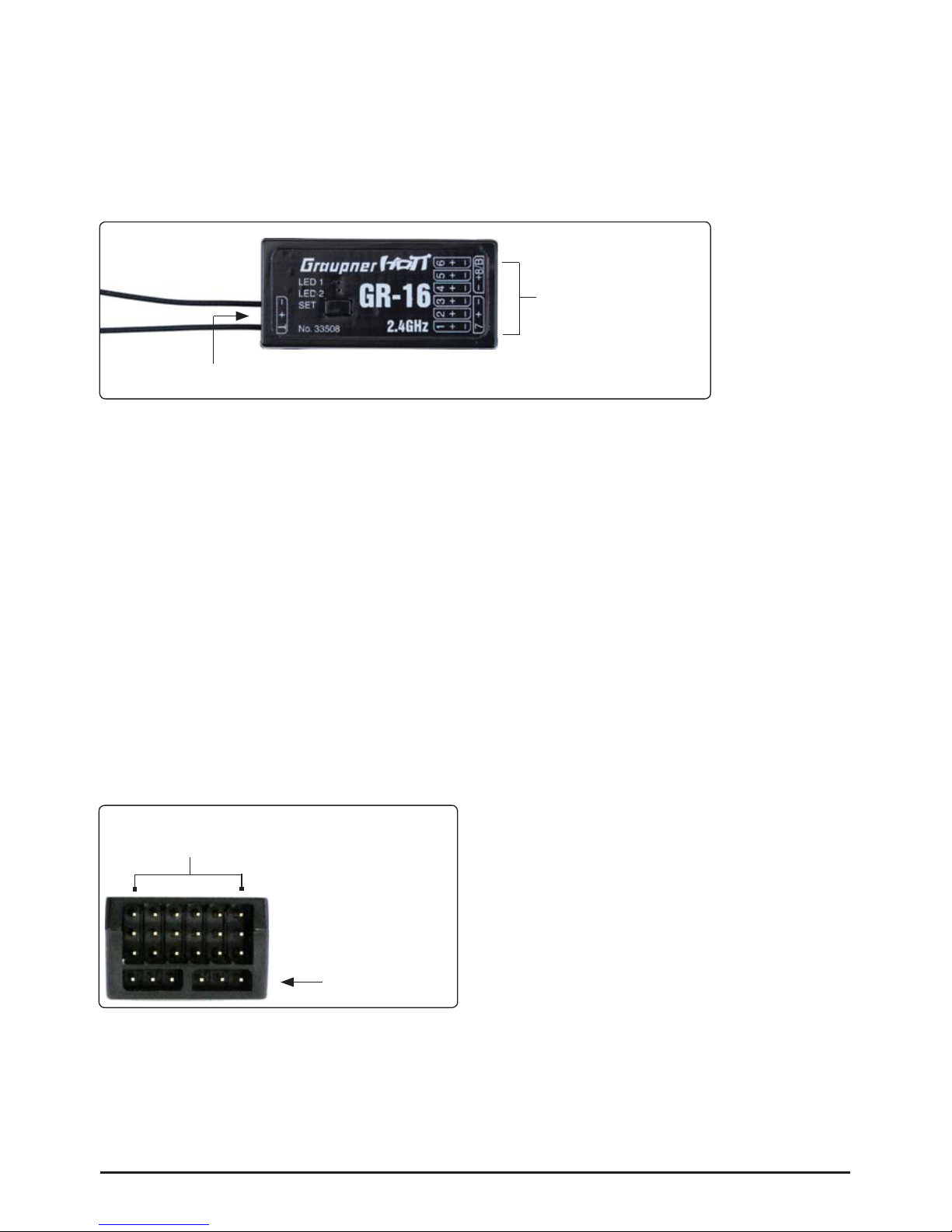
3. Receiver
3.1 Connections
Plug the servos into the row of sockets on the right-hand end of the receiver. The connector system is
polarised; note the small chamfer on one edge. Never use force - the plugs should engage easily and
fully. The socket polarity is also marked on the case: brown wire (-), red (+) and orange (signal).
The servo sockets of the Graupner-HoTT 2.4 receiver are numbered. The socket marked “- +/B” is
intended for the battery . If necessary, a servo can be connected to this socket in parallel with the power
supply; a Y-lead (Order No. 3936.11) is required for this.
It is also possible to program the channel 8 for the sum signal using a Graupner HoTT transmitter or the
SMART -BOX (Order No. 33700). This is important for certain optional devices which require this signal.
Power supply for receiver 33508, 33512
When using High Power servos, connect the receiver power supply/s preferably to the vertical ports of
the receiver. If necessary, the servos can be connected to this sockets in parallel with the power supply;
a Y-lead (Order No. 3936.11) is required for this.
The lower sockets (33508 and 33512) should not be used, because an increased voltage drop occurs.
When using a dual power supply, use the sockets on the outside:
Receiver 33506/33508 (GR-12/GR-16): Channel 1 and 6 (or 2 and 5)
Receiver 33512 (GR-24): Channel 11 and 12
The socket marked “T” - telemetry interface - on the left-hand end of the receiver is intended for the
optional telemetry sensors. This socket is also used for loading fi rmware updates in conjunction with the
USB interface. This socket is also polarised; note the small chamfer on one edge. Never use force - the
plugs should engage easily and fully . The socket polarity is also marked on the case: brown wire (-), red
(+) and orange (T).
Servo sockets
Programming socket
RECEIVER 33508
Channel 1 and 6
do not use
Page 5

Getting Started Graupner HoTT 2.4 05
3.2. Low voltage warning
If the receiver voltage falls below 3.8 V, the transmitter’s RF module generates a low voltage warning in
the form of a “general alarm sound”: a steady beeping at intervals of about one second.
Note: The warning threshold can be programmed in the TELEMETRY menu of the transmitter (or with
the SMART-BOX). Please read the manual of your transmitter.
3.3. Temperature warning
If the receiver temperature falls below -10° C or exceeds +70° C, the transmitter’s RF module generates
a temperature warning in the form of a “general alarm sound”: a steady beeping at intervals of about
one second.
Note: The warning threshold can be programmed in the TELEMETRY menu of the transmitter (or with
the SMART-BOX). Please read the manual of your transmitter.
3.4. Firmware updates
Firmware updates for the receiver can be transferred via the programming socketvia the programming
socket on the side of the unit, in conjunction with a PC running Windows XP, Vista or 7. For this you
also require the USB interface, Order No. 7168.6, and the adapter lead, Order No. 7168.6A, which are
available separately.
The programs and fi les required for this are available from www.graupner.de in the Download area for
the corresponding products.
See also chapter 4.2.
Page 6

4. Firmware update Graupner-HoTT 2.4 Transmitter and receiver
Firmware updates for the transmitter RF module can be transferred via the DATA or telemetry interface
in conjunction with a PC running Windows XP, Vista or 7. For this you also require the USB interface,
Order No. 7168.6, and the adapter lead, Order No. 7168.6A or 7168.6S, which are available separately.
The programs and fi les required for this are available from www.graupner.de in the Download area for
the corresponding products.
Install the Firmware Update Utility Graupner and the USB drivers on your computer. Check the system
requirements!
This socket is polarised; note the small chamfer on one edge. Never use
force - the plug should engage easily and fully.
4.1. Receiver
Connect the adapter lead to the socket on the left-hand end of the receiver, as shown in the illustration. This socket is also polarised; note the
small chamfer on one edge. Never use force - the plug should engage
easily and fully.
The black wire (-) must be at the front, the white wire (T) at the back.
4.2. Update procedure
Ensure that the adapter lead is confi gured as shown in the illustrations, and is connected correctly to
the transmitter or receiver.
Start the Firmware Upgrade Graupner Studio.
Under „Port Select“ select the correct
COM port „Silicon Labs CP210x USB
to UART Bridge“, i.e. the one to which
the USB lead is connected.
Choose the „HoTT receiver update“
menu. Now click on the “File Browse”
button and select the the previously
loaded fi rmware fi le ending in *.bin. If
everything is correct, the fi le will ap-
pear in the corresponding window.
The fi rmware fi les are encoded in product-specifi c form, i.e. if you accidentally select a fi le which does
not match the product (e.g. transmitter update fi le instead of receiver fi le), then the pop-up window “Pro-
duct code error” will appear, and you will not be able to start the update procedure (fi g. A).
06 Getting Started Graupner HoTT 2.4
Page 7

Press the “Program” button in the software. Wait briefl y until
you see movement in the progress bar. This make take up to
fi ve seconds, depending on the computer (fi g. B).
Receiver: press the SET button, and switch the receiver on
while you hold it pressed in.
After a few seconds the Status screen displays the message
“Found target device…”; you can now release the button, and
the fi rmware update process commences.
If the device is not recognised, if the pop-up window “T arget device ID not found” appears, or if the process fails before 100%
is reached, you must restart the update procedure. Repeat all
the steps as described above.
The Status display and the Progress bar show the progress of
the fi rmware update. The update is completed when the popup
message “Download Process Complete” appears (fi g. C).
During the update process both red and green LEDs on the receiver glow constantly. When it is complete, the red LED starts
fl ashing, the green goes out.
Switch your receiver off, and disconnect the adapter lead.
Caution: after completing an update process, you must initialise the device before using it, i.e. reset it to the factory
default values.
Initialisation:
Press and hold the SET button on the receiver and switch it on, the red and green LED‘s are blinking.
After about three seconds the LED‘s expires, then only the red LED fl ashes. Release now the SET
button, the initialization is complete.
Please note:
The initialisation procedure erases ALL the settings you have entered. Where necessary, you will need
to program your preferred settings again.
Any settings you have entered using the SMART-BOX are also lost when you initialise the receiver. If you carry out a receiver fi rmware update, you will need to re-enter these settings.
The latest version of these instructions can be found at www.graupner.de
Getting Started Graupner HoTT 2.4 07
A
C
B
Page 8

Konformitätserklärung gemäß dem Gesetz über Funkanlagen und
Telekomunikationsendeinrichtungen (FTEG) und der Richtlinie 1999/5/EG (R&TTE)
Declaration of Conformity in accordiance with the Radio and Telecomunikations Terminal Equipment
Act (FTEG) and Directive 1999/5/EG (R&TTE)
Graupner GmbH & Co. KG
Henriettenstraße 94-96
D-73230 Kirchheim/Teck
erklärt, dass das Produkt:
declares that the product
Geräteklasse: 2
Equipment class
den grundlegenden Anforderungen des § 3 und den übrigen einschlägigen Bestimmungen des
FTEG (Artikel 3 der R&TTE) entspricht.
complies with the essential requirements of § 3 and the other relevant provisions of the FTEG (Article 3 of the
R&TTE Directive).
Angewendete harmonisierte Normen:
Harmonised standards applied
EN 60950:2006
EN 301 489-1 V1.7.1
EN 301 489-3 V1.4.1
EN 300 328 V1.7.1
Health and safety requirements pursuant to § 3 (1) 1. (Article 3 (1) a))
Protection requirement concernig electromagnetic compatibility
§ 3 (1) 2, Artikel 3 (1) b))
Measures for the efficient use of the radio frequency spectrum
§ 3 (2) (Article 3 (2))
Kirchheim, 19. Dezember 2011
Stefan Graupner, Geschäftsführer
Stefan Graupner, Managing Director
Graupner GmbH & Co. KG Henriettenstraße 94-96 D-73230 Kirchheim/Teck Germany
Tel: 07021/722-0 EMail: info@graupner.deFax: 07021/722-188
Gesundheit und Sicherheit gemäß § 3 (1) 1. (Artikel 3 (1)a))
Schutzanforderungen in Bezug auf elektromagnetische
Verträglichkeit § 3 (1) 2, Artikel 3 (1) b))
Maßnahmen zur effizienten Nutzung des Frequenzspektrums
§ 3 (2) (Artikel 3 (2))
mx-12 HoTT - No. 33112, mx-16 HoTT - No. 33116,
mx-20 HoTT - No. 33124,
GR-12 HoTT - No. 33506, GR-16 HoTT - No. 33508,
GR-24 HoTT - No. 33512
0678
08 Getting Started Graupner HoTT 2.4
Page 9

Getting Started Graupner HoTT 2.4 09
ENVIRONNEMENTAL PROTECTION NOTES
When this product comes to the end of its useful life, you must not dispose of it in the ordinary
domestic waste. The correct method of disposal is to take it to your local collection point for recycling electrical and electronic equipment. The symbol shown here, which may be found on the
product itself, in the operating instructions or on the packaging, indicates that this is the case.
Individual markings indicate which materials can be recycled and re-used. You can make an important
contribution to the protection of our common environment by re-using the product, recycling the basic
materials or recycling redundant equipment in other ways.
Remove batteries from your device and dispose of them at your local collection point for batteries.
In case of R/C models, you have to remove electronic parts like servos, receiver, or speed controller
from the product in question, and these parts must be disposed of with a corresponding collection point
for electrical scrap.
If you don’t know the location of your nearest disposal centre, please enquire at your local council offi ce.
FCC INFORMATION
Graupner GR-16 HoTT #33508 and GR-24 #33512
FCC ID: ZKZ-33508 and ZKZ-33512
FCC Label Compliance Statement
This device complies with Part 15C of the FCC Rules.
Operation is subject to the following two conditions:
1. This device may not cause harmful interference.
2. This device must accept any interference received, including interference that may cause undesired
operation.
WARNING:
Changes or modifi cations not expressly approved by the party responsible for compliance could void
the user‘s authority to operate the equipment.
NOTE
This equipment has been tested and found to comply with the limits for a Class B digital device, pursuant to Part 15C of the FCC Rules. These limits are designed to provide reasonable protection against
harmful interference in a residential installation. This equipment generates uses and can radiate radio
frequency energy and, if not installed and used in accordance with the instructions, may cause harmful
interference to radio communications.
However, there is no guarantee that interference will not occur in a particular installation. If this equipment does cause harmful interference to radio or television reception, which can be determined by turning the equipment off and on, the user is encouraged to try to correct the interference by one or more
of the following measures:
• Reorient or relocate the receiving antenna.
• Increase the separation between the equipment and receiver.
• Connect the equipment into an outlet on a circuit different from that to which the receiver is connec ted.
• Consult the dealer or an experienced radio/TV technician for help.
RF Exposure Statement
This device has been evaluated to meet the FCC RF exposure requirement when used in combination
with the genuine Graupner HoTT accessoires and operated with a minimum distance of 20 cm between
the antenna and your body.
Page 10

10 Getting Started Graupner HoTT 2.4
ACCESSORIES:
Order No. 33505 Receiver GR-12S HoTT
Order No. 33506 Receiver GR-12 HoTT
Order No. 33508 Receiver GR-16 HoTT
Order No. 33512 Receiver GR-24 HoTT
Order No. 33600 Graupner HoTT GPS/Vario
Module
Page 11

ACCESSORIES:
Getting Started Graupner HoTT 2.4 11
Order No. 33611 General Air-Module Graupner HoTT
Vario, RPM, Fuel, 2x temperature, 2x
voltage, max. current 40A, capacity,
single cell voltage 2 -6 S
Order No. 33615
Order No. 33613 Graupner HoTT Temperature Sensor
200°C, voltage sensor
Graupner HoTT RPM Optical Sensor
Order No. 33700 HoTT SMART BOX
Order No. 33612 Graupner HoTT Temperature Sensor
120°C, voltage sensor
Page 12

Graupner GmbH & Co. KG
Henriettenstraße 94 – 96
D-73230 Kirchheim/Teck
Germany
www.graupner.de
Änderungen sowie Liefermöglichkeiten vorbehalten. Lieferung durch den Fachhandel. Bezugsquellen
werden nachgewiesen. Für Druckfehler kann keine Haftung übernommen werden.
Specifi cations and availability subject to change. Supplied through specialist model shops only. We will
gladly inform you of your nearest supplier. We accept no liability for printing errors.
Sous réserve de modifi cations et de possibilité de livraison. Livraison uniquement au travers de maga-
sins spécialisés en modélisme. Nous pourrons vous communiquer l’adresse de votre revendeur le plus
proche. Nous ne sommes pas responsables d’éventuelles erreurs d’impression.
Con riserva di variazione delle specifi che e disponibilità del prodotto. Fornitura attraverso rivenditori
specializzati.Saremmo lieti di potervi indicare il punto vendita più vicino a voi. Si declina qualsiasi responsabilità per errori di stampa.
HoTT 1.0 / November 2012 - EN V1.5
 Loading...